
Advanced RF Measurement Techniques with SW-based Modular ...
32
Advanced RF Measurement Techniques with SW-based Modular Signal Analyzers Andreas Gustafsson National Instruments
Transcript of Advanced RF Measurement Techniques with SW-based Modular ...

Advanced RF Measurement
Techniques with SW-based Modular
Signal Analyzers
Andreas Gustafsson
National Instruments

Modern RF Measurement System
Software for Wireless Standards
(802.11 a/b/g/n, GSM, EDGE, WCDMA,
RFID, WiMAX,
GPS, and so on)
Modular Hardware Architecture

What are Vector Signal Analyzers (VSAs)?
• Convert time domain to frequency domain
• Both Amplitude and phase
Amplitude
(power)
Time Domain
Measurements

Single vs. Multi-Stage Architectures
Single-Stage Downconversion
1-stage = 1 mixer (PXIe-5663)
Multi-Stage Downconversion
ADC
3-stage = 3 mixers (PXIe-5665)
Benefits
- Faster Tuning
- Simpler design = savings on
hardware
Benefits
- Image rejection
- Improved Performance
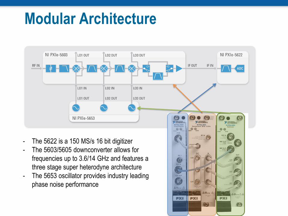
Modular Architecture
- The 5622 is a 150 MS/s 16 bit digitizer
- The 5603/5605 downconverter allows for
frequencies up to 3.6/14 GHz and features a
three stage super heterodyne architecture
- The 5653 oscillator provides industry leading
phase noise performance

Architecture of a 4-channel VSA
ADC
ADC
Rx0
Rx1
ADC Rx2
ADC Rx3
DDC
16
Shared Local
Oscillator Shared ADC
Sample Clock
I
Q
DDC
16 I
Q
DDC
16 I
Q
DDC
16 I
Q
10 MHz
OCXO
• Shared clocks
• Local oscillator
• ADC clock
• NCO on DDC
• Example shown
with PXIe-5663

NI PXIe-5665
High Performance Vector Signal Analyzer • 20 Hz to 3.6 or 14 GHz frequency range • Phase noise -129 dBc/Hz at 10 kHz offset • Average noise floor: -165 dBm/Hz @ 1 GHz • TOI - +24 dBm • WCDMA ACLR: -80 dBc • 0.1 dB Amplitude Accuracy • .33% 256 QAM EVM

5622
5603
5653
ADC RF In DDC/F
FT
Achieving Improved VSA Measurements ① Calibration
a) System Calibration, Cal tone
b) IF Equalization
② Dynamic Range and Noise Floor
a) Resolution Bandwidth
b) IF Filters
c) Instantaneous Bandwidth
d) Min ACPR
e) pre amp
f) noise correction
③ Speed –
a) Phase noise tuning
b) RF list mode

5622
5603
5653
ADC RF In DDC/F
FT
Achieving Improved VSA Measurements ① Calibration
a) System Calibration, Cal tone
b) IF Equalization
② Dynamic Range and Noise Floor
a) Resolution Bandwidth
b) IF Filters
c) Instantaneous Bandwidth
d) IF gain
e) pre amp
f) noise correction
③ Speed –
a) Phase noise tuning
b) RF list mode

Challenges – Calibration
• Temperature drift
• Regularity of calibration
• Individual module calibration
• Use of external high precision
instrumentation
1 2 3

a) Solution – Factory & Self Calibration
• Factory Calibration on each module:
Calibrated for accurate frequency and amplitude response at manufacturing • RF Response – Frequency and temp
compensation
• IF Response – response of IF filters is measured
Ships with calibration certificate verifying NIST-traceable accuracy
• Self Calibration –
NI 5603 measures the reference source
Compares the resulting measurements to a value stored in the NI 5603 EEPROM
Tip #1

Solution – Use of Cal Tone
Built in high precision cal-tone calibrates the down-
converter
NI RFSA driver combines the calibrated values for a
system calibration
5622
5603
5653
ADC RF In DDC/FF
T
Cal tone
Tip #1

b) Use of equalization with calibration
• Equalization is used to compensate for non linear components of filters (group delay)
• Envelope Delay technique Apply information to a carrier (AM modulated) and measure how much the information is delayed using a phase detector working at the modulation frequency (612.5MHz)
• Results in better EVM measurements
Tip #2

WCDMA EVM Improvements with Equalization
No equalization
Equalization

5622
5603
5653
ADC RF In DDC
Achieving Improved VSA Measurements ① Calibration
a) System Calibration, Cal tone
b) IF Equalization
② Dynamic Range and Noise Floor a) Resolution Bandwidth
b) IF Filters
c) Instantaneous Bandwidth
d) IF gain
e) pre amp
f) noise correction
③ Speed –
a) Phase noise tuning
b) RF list mode

Challenge – Measuring Low Level Signals
• ADC resolution determines floor on achievable dynamic
range
• Larger signals blocks / masks the weak signal which may
get quantized with only a few bits and end up in the noise

a) Resolution Bandwidth (RBW)
Effects of lowering resolution bandwidth: Increases frequency resolution (# of spectral lines)
Lowers DANL (Displayed Average Noise Level)
• Increases dynamic range – narrowband signals only
Increases acquisition time.
Tip #3
RBW=10kHz RBW=300kHz

b) Use of Appropriate IF Filters
• Some VSAs support multiple IF filter options
Through - Provides a nominal 50 MHz bandwidth
• Advantages - Speed
Narrow (300 KHz) - Provides a nominal 300 kHz
• Advantages – Lower noise floor
f1 f2 f3
FFT1 50 MHz Filter
300 kHz Filter
FFT1
5622
5603
5653
ADC RF In FFT
Tip #4

c) Use of Instantaneous Bandwidth
• The bandwidth in which all frequency components can be simultaneously captured and analyzed.
• Increase in measurement speed for large spans
• IF path selected based on instantaneous BW
• Resolution bandwidth applies after the ADC and instantaneous bandwidth applies before the ADC
Span
IBW
FFT1 FFT3 FFT2 FFTN ……..
Total Measurement Time
Tip #5

d) IF Gain Optimization
• Adjusts variable attenuators and IF gain to optimize complete range
of ADC
• Applies only to narrow bandwidth IF filter (300 KHz)
• Affects noise floor but not linearity
5622
5603
5653
ADC RF In FFT
Tip #6

Effect of IF Gain on Adjacent Tones
ADC
1V pk to pk (16 bits)
ADC
ADC IF Gain Applied
Bandwidth No IF Gain 1V pk to pk (16 bits)
1V pk to pk (16 bits)

Noise Floor and Time Effects of IF Filters
• 5-6dB improvement with 300 KHz filter Path + IF Gain
• Takes longer to sweep with the 300 KHz filter path
• Adjacent tones can be detected

e) Use of optional pre amplifier
• NI 5603/5605 includes
Switchable 15 dB preamplifier before the first mixer
Mechanical step attenuator
Solid state step attenuator
• 15 dB pre-amp offers lower noise floor
5622
5603
5653
ADC RF In FFT
Tip #7

Pre-amplification
• NI 5665 features an optional built in pre amplifier
• ANL of -165 dBm/Hz with pre amp

f) Noise Correction
1. Disconnect input – connect to terminator and measure noise floor
2. Store measures results in cache
3. Connect input and make measurement
4. Subtract stored values from measurement to get noise corrected data
RF In
Disconnect
RF In
Noise Corrected Data
Tip #8

ACP Measurements with Noise Correction
Without Noise Correction
• ~64 dBc ACPR
With Noise Correction
• ~70 dBc ACPR
Note: Perform noise correction when any parameter such as
frequency or amplitude changes.

5622
5603
5653
DAC RF In FFT
Achieving Improved VSA Measurements ① Calibration
a) System Calibration, Cal tone
b) IF Equalization
② Dynamic Range and Noise Floor
a) Resolution Bandwidth
b) IF Filters
c) Instantaneous Bandwidth
d) IF gain
e) pre amp
f) noise correction
③ Speed –
a) Phase noise tuning
b) RF list mode

Tuning Time
Mode Tuning Speed
(1 GHz Step)
Frequency
Accuracy
Phase Noise (10
KHz)
Normal 9.3 ms 0.1 ppm
-133 dBc/Hz
Fast 2.3 ms 1 ppm
-130 dBc/Hz
Tip #9

RF List Mode vs. Traditional Method
Freq 1
Deterministic Triggers
Freq 2
SW Call
Freq 1
SW Call 2 SW Call 1
Traditional Software List
RF List Mode
Freq 3
Freq 2 Freq 3
SW Call 3
∆t
Time savings
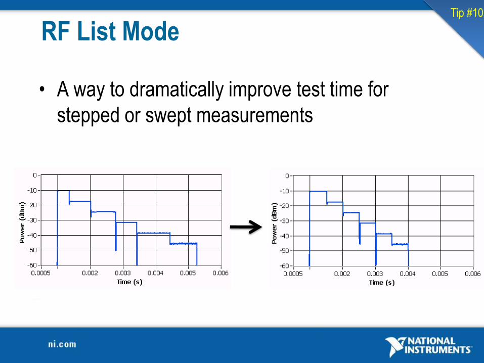
RF List Mode
• A way to dramatically improve test time for
stepped or swept measurements
Tip #10

Deterministic Scanning • 32,000 configuration scan list
• Internal and external trigger connections available
Scanning Support
Start
Switch:
Connect next channel in scan list
Switch:
Output Trigger
Instrument:
Input Trigger
Instrument:
Perform Measurement
Instrument:
Output Trigger
Switch:
Input Trigger

Summary
• Modern Signal Analyzers based on a SW and
modular approach are very powerful when some
challenges are overcome:
Calibration: New techniques enhance phase and
amplitude accuracy
Dynamic Range: IF path selection, gain and noise
correction can greatly improve D.R. and noise floor
Speed: Use techniques to improve measurement
speed such as RF list mode and tuning time options


