Advanced Process Manager Parameter Reference Dictionary...2.9 Digital Composite (DigComp) 2.10...
306
Advanced Process Manager Parameter Reference Dictionary AP09-640
Transcript of Advanced Process Manager Parameter Reference Dictionary...2.9 Digital Composite (DigComp) 2.10...
Advanced Process ManagerParameter Reference
Dictionary
AP09-640

ImplementationAdvanced Process Manager - 3
Advanced Process ManagerParameter Reference
Dictionary
AP09-640Release 600
2/99

Notices and Trademarks
© Copyright 1999 by Honeywell Inc.
Revision 02 – February 1, 1999
While this information is presented in good faith and believed to be accurate,Honeywell disclaims the implied warranties of merchantability and fitness for aparticular purpose and makes no express warranties except as may be stated in itswritten agreement with and for its customer.
In no event is Honeywell liable to anyone for any indirect, special or consequentialdamages. The information and specifications in this document are subject tochange without notice.
TotalPlant and TDC 3000 are U.S. registered trademarks of Honeywell Inc.
Other brand or product names are trademarks of their respective owners.

APM Parameter Reference Dictionary 2/99
About This Publication
This publication defines the parameters for the APM data point types implementedthrough TotalPlant Solution (TPS) system network Release 600. TPS is the evolution of
TDC 3000X.

APM Parameter Reference Dictionary 2/99

Table of Contents
APM Parameter Reference Dictionary i 2/99
1 INTRODUCTION
1.1 Purpose1.2 Use of This Publication1.3 Parameter Definition Format1.4 Parameters Per Point Type and Algorithm Type1.5 Full Points and Component Points1.6 Abbreviations1.7 CL Access1.7.1 Parameters Not Accessible to CL1.7.2 CL Restricted Parameters
2 PARAMETERS PER POINT TYPE
2.1 Analog Input (AnalgIn)2.2 Analog Output (AnalgOut)2.3 Array2.4 Box (APM Box)2.5 Box Flag2.6 Box Numeric2.7 Box Timer2.8 Device Control (DevCont)2.9 Digital Composite (DigComp)2.10 Digital Input (DigIn)2.11 Digital Output (DigOut)2.12 IOP2.13 Logic2.14 Process Module (ProcMod)2.15 Universal Control Network2.16 UCN Node Data Point
3 PARAMETERS PER ALGORITHM TYPE
3.1 Auto Manual (AutoMan)3.2 Calculator (Calcultr)3.3 Data Acquisition (DataAcq)3.4 Flow Compensation (FlowComp)3.5 General Linearization (GenLin)3.6 High-Low Average (HiLoAvg)3.7 Incremental Summer (IncrSum)3.8 Middle-of-3 (MidOf3)3.9 Override Selector (ORSel)3.10 Pid3.11 Pid with External Reset Feedback (PidErfb)3.12 Pid with Feed Forward (PidFf)3.13 Pid with Position Proportional (PidPosPr)3.14 Position Proportional (PosProp)3.15 Ramp Soak (RampSoak)3.16 Ratio Control (RatioCtl)3.17 Summer3.18 Switch3.19 Totalizer (Totalizr)3.20 Variable Dead Time with Lead/Lag (VdtLdLag)
$–Y PARAMETER DEFINITIONS

APM Parameter Reference Dictionary ii 2/99

APM Parameter Reference Dictionary 1-1 2/99
1
INTRODUCTIONSection 1
1.1 PURPOSE
This publication defines the user-visible parameters that exist in the TotalPlant Solution(TPS) system Advanced Process Manager (APM) and Network Interface Module (NIM).It also provides listings of parameters that are applicable to various APM point types andalgorithms.
For information on how the parameters are related to each other in terms of point typesand algorithms, refer to the Advanced Process Manager Control Functions andAlgorithms manual in the Implementation/Advanced Process Manager - 1 binder.
1.2 USE OF THIS PUBLICATION
Use this publication during configuration and during operation when detailed informationabout APM and NIM parameters is required.
For use in data point configuration, this publication provides definitions for each entrythat can be made on the Advanced Process Manager Point Configuration Forms, in the Implementation/Advanced Process Manager, and in the Parameter Entry Displaysat the Universal Station.
For use in process operation, this publication provides information about the parametersthat appear for the process data points and APM Box Data Point on the displays ofUniversal Stations that are running with the Operator personality.
1.3 PARAMETER DEFINITION FORMAT
In this dictionary, the parameter definitions are listed in alphabetical order according tothe parameter name, which can be up to eight characters in length. Each parameter in thispublication is defined using the format shown below for the ALMOPT parameter, as anexample. The following paragraphs describe the entries that appear within eachparameter definition.
ALMOPT (DigIn)Type: e($ALMOPT)Lock: Eng/PBDefault: NonePtRes: APM
Alarming Option— Defines the alarming option for a digital input point whose DITYPEis Status.
Range: 0-None (No alarms are to be detected)1-Offnorml (Off Normal; alarm if current PV state is not the PVNORMAL state. PVNORMAL is
defined by the STATETXT(0) or STATETXT(1) descriptor, as configured by the user.)2-ChngofSt (An alarm is generated when the digital input changes state in either direction).
Helpful Hint: ALMOPT configuration requires DITYPE = Status.
APM Parameter Reference Dictionary 1-2 2/99
1.3
For many parameters, the function of the parameter is described using the long name ofthe parameter (Alarm Option), followed by a description as shown in the above example.Some parameters in this dictionary do not have functional descriptions following the longname; this is because the long name of the parameter sufficiently describes the parameterfunction.
Type
This entry is the data type that defines how the parameter is viewed by the system. Thefollowing data types are used in this dictionary:
• E:—Enumeration; the value for the parameter is chosen from a set of predefinedcharacter strings. In the above example, the enumerations of $ALMOPT are None,Offnorml.
• SD_ENM:—Self-Defining Enumeration; the value for the parameter is chosen fromthe user-defined character strings.
• Ent.Prm—consists of a 1-16 character tag name, a period, and a 1-8 characterparameter name.
• Integer—a 16-bit whole number that does not contain a decimal point (+ 32767).
• Logical—a binary type with the values of ON (True) and OFF (False), or 0 (Off) and1 (On).
• NaN—although not a data type, is used to represent "Not A Number" and is stored inIEEE format.
• Prm_Id—1-8 character parameter name.
• Real—a 32-bit floating-point number in IEEE format.
• String_L—a character string of maximum length = L. Same as Ascii_L.
• Time—The time of day in one of the following formats: DDD HH:MM:SS fordurations, and DDMMYY HH:MM:SS for an absolute date or time stamp.
• Universal Ent.Prm—Universal Entity Parameter Identifier. It is basically the sameas Ent.Prm, but the entity name can be entered as an external 16-character tag nameor as the APM's internal hardware reference address. The hardware reference addresssyntax can be used to access parameters of points (within this same APM) that areuntagged or tagged.

APM Parameter Reference Dictionary 1-3 2/99
1.3
The following are examples of hardware reference addresses*:Type Hardware Reference Address
AO Processor Output !AO11S03.OP (Parameter OP of Slot #3 of AO processor #11)
DI Processor PV !DI05S07.PVFL (Parameter PVFL of Slot #7 of DI processor #5)
DO Processor !DO15S12.SO (Parameter SO of Slot #12 of DO processor #15) Status Output
DO Processor !DO15S12.ONPULSE (Parameter ONPULSE of Slot #12 of DO ON Pulse Command processor #15)
DO Processor !DO15S12.OFFPULSE (Parameter OFFPULSE of Slot #12 of OFF Pulse Command DO processor #15)
Lock
The access lock defines "who" or "what" can change the parameter’s value or option andthe access level defines "who" or "what" is requesting a parameter value or option change.For example, if a requestor with an access level of Supr tries to change a parameter thathas an access lock of Engr, the request will be denied. The two charts below describe howaccess levels and access locks work.
Access Level Used By Who Or What When AParameter Change Request Is Made
Oper OperatorSupr or Sup SupervisorEngr, Eng, or Eg EngineerCont Continuous_Control (from a Module on the LCN)OnProc On ProcessAPMMCc APMM_Continuous_Control (from APMM)Prog CL/APM Sequence_ProgramsPtBld or PB Point_Builder (Data Entity Builder)
Access Lock Access Level of Requestors That Can Change The Parameter
Oper Oper Supr Engr Cont APMMCc Prog PtBldSupr Supr Engr Cont APMMCc Prog PtBldEngr Engr Cont APMMCc Prog PtBldOnProc Oper Supr EngrSup/Eg Supr EngrEgOnly EngrProg Cont APMMCc Prog PtBldEng/PB Engr PtBldPtBld PtBldView (Read Only)______________*The Analog Input address !AImmSss.Parameter is not supported because the Analog Input point does not havea useable default database.

APM Parameter Reference Dictionary 1-4 2/99
1.4Default
The default for the parameter is the default value assigned by the system. The systemautomatically enters the default value for a parameter when a range or a selection is notentered for a parameter during point building. The default values are also shown on theconfiguration forms and parameter entry displays.
PtRes
This defines where the parameter physically resides. The following residency locationsare used in the parameter definitions:
PtRes Definition
APM Advanced Process ManagerNIM Network Interface ModuleSI Serial Interface
Range
This defines the range of the value that can be entered for this parameter. Integers thatprecede APM resident enumeration parameters are sometimes needed by advanced CLusers. These integers specify the member’s position within the set (that is, the ordinal).CL programs external to the UCN (such as AM/CL) will see the same enumerationstrings, but in some cases, with different ordinal values.
Helpful Hint
Some parameter definitions contain a Helpful Hint box at the end of the definition. Thisbox contains additional information about the parameter, such as prerequisites, etc.
1.4 PARAMETERS PER POINT TYPE AND ALGORITHM TYPE
In addition to the parameter definitions, this dictionary also contains listings of theparameters that are applicable to each APM point type and algorithm type. Parameters-per-point-type are defined in Section 2; parameters-per-algorithm-type are defined inSection 3.
1.5 FULL POINTS AND COMPONENT POINTS
Separate functional elements of the APM are used to implement various parts of typicalcontrol loops and control strategies. Each of these functional elements can be assigned auser-defined tag name to allow for location-independent reference to the data associatedwith that function. For example, point tags are assigned by the user for analog input andanalog output slots. The I/O Processor data (engineering-unit range for inputs,characterization option for outputs, etc.) is configured as part of the point-build processfor these points. A separate tag is configured for each regulatory control (RegCtl) slotthat is linked to the assigned analog I/O tags through input/output connections.

APM Parameter Reference Dictionary 1-5 2/99
1.6The APM provides a configurable parameter called PNTFORM (Point Form) that allowsthe user to define which points are to be used as the primary operator interface for pointdata. The PNTFORM parameter provides the user with two choices for point form:"Full" and "Component." Points that are configured as having "Full" point form includedescriptor data and alarm-related parameters. This information is needed when the pointis to be used as the primary operator interface to the point’s data.
Points that are configured as having "Component" point form do not require descriptordata and alarm-related parameters, because this type of information is suppressed for"Component" points. This point form should be used for points that provide inputs to the"Full" point and also for those points that handle the outputs from the "Full" points."Component" points should be used as part of the "Full" point that has been designated aprimary operator interface point.
1.6 ABBREVIATIONSAM Application Module
AnalgIn Analog Input Data Point
AnalgOut Analog Output Data Point
AO Analog Output
APM Advanced Process Manager
APMM Advanced Process Manager Module
APM Box APM Box Data Point
Array Array Data Point
AutoMan Auto Manual algorithm
Box Box Data Point
Calcultr Calculator algorithm
CM Computing Module 50 or 60
DevCtl Device Control Data Point
DI Digital Input
DigComp Digital Composite Data Point
DigIn Digital Input Data Point
DigOut Digital Output Data Point
DISOE Digital Input Sequence of Events
DO Digital Output
Flag Flag Data Point
FlowComp Flow Compensation algorithm
FTA Field Termination Assembly
GenLin General Linearization algorithm
HiLoAvg High Low Average algorithm
HLAI High Level Analog Input
IncrSum Incremental Summer algorithm

APM Parameter Reference Dictionary 1-6 2/99
1.6
IOL I/O Link
IOP I/O Processor
Logic Logic Data Point (Slot)
LCN Local Control Network
LLAI Low Level Analog Input (or LLAI-8)
LLMUX Low Level Analog Input Multiplexer (or LLAI-16/32)
MidOf3 Middle-of-3 Selector algorithm
NIM Network Interface Module
ORSel Override Selector algorithm
PI Pulse Input
Pid Proportional, Integral, Derivative,
PidErfb Proportional, Integral, Derivative with External Reset Feedback algorithm
PidFf PID with Feedforward algorithm
PidPosPr PID With Position Proportional algorithm
PosProp Position Proportional algorithm
ProcMod Process Module Data Point
RampSoak Ramp Soak algorithm
RatioCtl Ratio Control algorithm
RegCtl Regulatory Control Data Point or algorithm
RegPV Regulatory PV Data Point or algorithm
RHMUX Remote Hardened Analog Input Multiplexer (or RHMUX–16/32)
SI Serial Interface
SDI Serial Device Interface
STI Smart Transmitter Interface
Switch Switch algorithm
Summer Summer algorithm
Timer Timer Data Point
Totalizr Totalizer algorithm
UCN Universal Control Network
VdtLdLag Variable Deadtime Lead Lag algorithm
APM Parameter Reference Dictionary 1-7 2/99
1.7
1.7 CL ACCESS
1.7.1 Parameter Not Accessible to CL
Parameter $EVNTREC is not accessible to Control Language (CL) sequences.
1.7.2 CL Restricted Parameters
The following parameters are not accessible to PM/CL sequences. They are not directlyavailable to AM/CL sequences. Access to AM/CL is through a custom data segmentparameters attached to AM regulatory points as described below.
BHALMFL1-BHALMFL7
NODESTS
NODETYP
UCNRECHN
These parameters are available to user schematics using the NIM reserved data point, e.g.,$NMuuBnn.param, where uu = UCN number and nn = UCN node number.
AM/CL programs can access the restricted parameters as Regulatory Point General inputs(using ordinary point parameter access). They must be transferred to parameters of AMregulatory points. There are two ways to do this:
1. Boolean parameters (BHALMFLn), can be referenced as general inputs to a Switch algorithm. A CL program can access the switch parameters.
2. For Enumerations (NODEOPER, NODESTS, NODETYP, POSITION, ANDUNRECHN) a custom data segment is created to allow the parameters to bereferenced as general inputs and transferred to user-defined parameters (of a RegCtlPoint) that can be accessed by Cl.

APM Parameter Reference Dictionary 1-8 2/99
APM Parameter Reference Dictionary 2-1 2/99
2
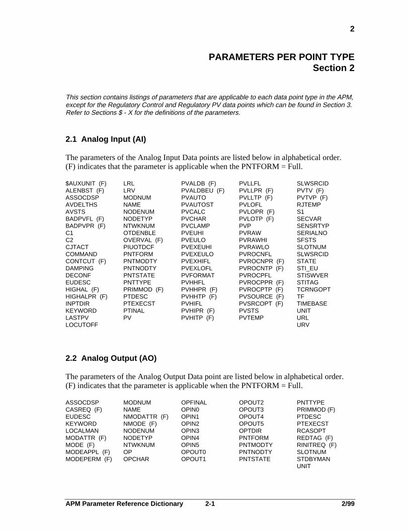
PARAMETERS PER POINT TYPESection 2
This section contains listings of parameters that are applicable to each data point type in the APM,except for the Regulatory Control and Regulatory PV data points which can be found in Section 3.Refer to Sections $ - X for the definitions of the parameters.
2.1 Analog Input (AI)
The parameters of the Analog Input Data points are listed below in alphabetical order.(F) indicates that the parameter is applicable when the PNTFORM = Full.
$AUXUNIT (F) LRL PVALDB (F) PVLLFL SLWSRCIDALENBST (F) LRV PVALDBEU (F) PVLLPR (F) PVTV (F)ASSOCDSP MODNUM PVAUTO PVLLTP (F) PVTVP (F)AVDELTHS NAME PVAUTOST PVLOFL RJTEMPAVSTS NODENUM PVCALC PVLOPR (F) S1BADPVFL (F) NODETYP PVCHAR PVLOTP (F) SECVARBADPVPR (F) NTWKNUM PVCLAMP PVP SENSRTYPC1 OTDENBLE PVEUHI PVRAW SERIALNOC2 OVERVAL (F) PVEULO PVRAWHI SFSTSCJTACT PIUOTDCF PVEXEUHI PVRAWLO SLOTNUMCOMMAND PNTFORM PVEXEULO PVROCNFL SLWSRCIDCONTCUT (F) PNTMODTY PVEXHIFL PVROCNPR (F) STATEDAMPING PNTNODTY PVEXLOFL PVROCNTP (F) STI_EUDECONF PNTSTATE PVFORMAT PVROCPFL STISWVEREUDESC PNTTYPE PVHHFL PVROCPPR (F) STITAGHIGHAL (F) PRIMMOD (F) PVHHPR (F) PVROCPTP (F) TCRNGOPTHIGHALPR (F) PTDESC PVHHTP (F) PVSOURCE (F) TFINPTDIR PTEXECST PVHIFL PVSRCOPT (F) TIMEBASEKEYWORD PTINAL PVHIPR (F) PVSTS UNITLASTPV PV PVHITP (F) PVTEMP URLLOCUTOFF URV
2.2 Analog Output (AO)
The parameters of the Analog Output Data point are listed below in alphabetical order.(F) indicates that the parameter is applicable when the PNTFORM = Full.
ASSOCDSP MODNUM OPFINAL OPOUT2 PNTTYPECASREQ (F) NAME OPIN0 OPOUT3 PRIMMOD (F)EUDESC NMODATTR (F) OPIN1 OPOUT4 PTDESCKEYWORD NMODE (F) OPIN2 OPOUT5 PTEXECSTLOCALMAN NODENUM OPIN3 OPTDIR RCASOPTMODATTR (F) NODETYP OPIN4 PNTFORM REDTAG (F)MODE (F) NTWKNUM OPIN5 PNTMODTY RINITREQ (F)MODEAPPL (F) OP OPOUT0 PNTNODTY SLOTNUMMODEPERM (F) OPCHAR OPOUT1 PNTSTATE STDBYMAN
UNIT

APM Parameter Reference Dictionary 2-2 2/99
2.3
2.3 Array
The parameters of the Array Data Point are listed below in alphabetical order.
AB_DATA1 ERRCODE NN PNTNODTY STRDESCAB_DATA2 EXTDATA NNDESC PNTTYPE STRLENAB_DATA3 FL NNUMERIC PRIMMOD (F) STRSTIXAB_DATA4 FLDESC NNSTIX PTDESC STSMSGASSOCDSP FLSTIX NODENUM SCANPRI TIMEAUXDATA1 FTANUM NODETYP SLOTNUM TIMEDESCAUXDATA2 INITREQ NSTRING SPLOCK TIMESECSAUXDATA3 IOPNUM NTIME STR8 TIMESTIXAUXDATA4 KEYWORD NTWKNUM STR16 UNITBADPVFL (F) NFLAG OVERLAP STR32 USERIDDEVADDR PNTFORM STR64
PNTFORM STR64
2.4 Box (APM Box)
The parameters of the Advanced Process Manager Box Data Point are listed below inalphabetical order.
BADPVTXT IOLPERSW LSPPXORN NODESTS SAFOPCMDCHPINOPR IOMCARD LSUCNORN NODETYP SCANRATECRUCNORN IOMCHAER MDMHWREV NODFSTAT SCANPERCRIOLORN IOMCHASL MINUTE NPMSLOT SECONDCRPPXORN IOMCHBER MONTH NPVSLOT SEQPRGSZCTLOPT IOMCHBSL MOVPVTXT NSTRING SEQPROCCTLPATCH IOMCMD NARRSLOT NTIME STR8CYCLETIM IOMCOMER NCTLSLOT NTIMER SUMSLTSZDATE IOMFILE NDCSLOT PKGOPT SWTCHACTDAY IOMOPER NDEVSLOT PMMCHAER TIMEDB_VALID IOMRECHN NFASTCTL PMMCHASL TMCMDEUNDESC IOMREALT NFASTDC PMMCHBER TMPVFL IOMSEVER NFASTDEV PMMCHBSL TMSPFTA1TYPE IOMSTS NFASTLOG PMMCMD TMRVFTA2TYPE IOMTYPE NFASTPV PMMCOMER TMSOHOUR IONTOKEN NFLAG PMMCTLST TMSTIOLASTS IOP NLOGSLOT PMMFLPOS TMTBIOLBSTS IOPNUM NN PMMOPER UTSDRIFTIOLCHAER IOPSTR1 NNUMERIC PMMRECCH UTSNODEIOLCHASL IOPSTR2 NODEASSN PMMSEVER UTSTBCRVIOLCHBER IORECCHN NODECMD PMMSFSTS UTSTIMEIOLCHBSL IOSTKNDR NODECONF PMMSTS UTSTIMSTIOLCHERT IOSSTS NODENUM POSITION WEEKDAYIOLCMD IOTKNSTL NODEOPER RJTEMP YEAR
LSIOLORN
Some of the parameters in the above listing are arrays and are not defined in thispublication.

APM Parameter Reference Dictionary 2-3 2/99
2.5
2.5 Box Flag
The parameters of the Box Flag Data Point are listed below in alphabetical order. (F)indicates that the parameter is applicable when the PNTFORM = Full; an * indicates thatthe parameter is applicable to flag slots 1-128.
$AUXUNIT (F)* EIPPCODE (F)* NODETYP PRIMMOD (F)* SLOTNUMALENBST (F)* EUDESC NTWKNUM PTDESC STATE0ALPRIOR HIGHAL (F)* OFFNRMPR (F) PV STATE1ASSOCDSP KEYWORD PNTNODTY PVFL STATETXTBOXCLR NAME PNTFORM S0BOXCLR UNITCONTCUT (F)* NODENUM PNTTYPE S1BOXCLR
2.6 Box Numeric
The parameters of the Box Numeric Data Point are listed below in alphabetical order.
ASSOCDSP NODENUM PNTNODTY PRIMMOD (F) PVFORMATEUDESC NODETYP PNTFORM PTDESC SLOTNUMKEYWORD NTWKNUM PNTTYPE PV UNITNAME
2.7 Box Timer
The parameters of the Box Timer Data Point are listed below in alphabetical order.
ASSOCDSP NODENUM PTDESC RV STATECOMMAND NODETYP PERIOD SLOTNUM TIMEBASEEUDESC NTWKNUM PRIMMOD (F) SO TIMOUTFLKEYWORD PNTNODTY PV SP UNITNAME PNTTYPE

APM Parameter Reference Dictionary 2-4 2/99
2.8
2.8 Device Control (DevCtl)
The parameters of the Device Control Data Point are listed below in alphabetical order.(F) indicates that the parameter is applicable when the PNTFORM = Full.
$AUXUNIT (F) (#Inputs>0) MAINDAT OVRDALPR (F)ACCELTIM MAINTOPT OVRDSIFLALENBST (F) MANMODFL P0 (#Outputs>0)ASSOCDSP MASKTIM P1 (#Outputs>0)BADPVFL (F) MAXTIM0H P2 (#Outputs>0)BADPVPR (F) MAXTIM1H PAUSETIMBADPVTXT (#Inputs>0) MAXTIM2H PERIODBADSVFL MAXTRAN0 PGALGID 1-4BADSVPR (F) MAXTRAN1 PGDSTN 1-4BOXCLR MAXTRAN2 PGPLSWTH 1-4BYPASS MODATTR (#Outputs>0) PGSO 1-4CMDDISFL MODE (#Outputs>0) PIALGID 1-12CMDDISPR (F) MODEAPPL (#Outputs>0) PIDEADBD1-12CMDFALFL MODEPERM (#Outputs>0) PINN 1-12CMDFALTM MODNUM PISO 1-12CONTCUT (#Inputs>0) MOMSTATE (#Outputs>0) PISRC 1-12D1 (#Inputs=1) MOVPVFL (#Inputs>0) PNTFORMD1_0 (#Inputs=1) MOVPVTXT PNTMODTYD1_1 (#Inputs=2) NAME PNTNODTYD2 (#Inputs=2) NI0 (#Outputs>0) PNTSTATED2D1_00 (#Inputs=2) NI1 (#Outputs>0) PNTTYPED2D1_01 (#Inputs=2) NI2 (#Outputs>0) PRIMMOD (F)D2D1_10 (#Inputs=2) NMODATTR (#Outputs>0) PTDESCD2D1_11 NMODE (#Outputs>0) PTEXECSTDB_VALID NN PTINALDEADBAND NNINSET 1-10 PULSEWTH (#Outputs>0)DEADTIME (#Inputs>0) NODENUM PV (#Inputs>0)DISRC 1 - 2 (#Outputs>0) NODETYP PVAUTO (#Inputs>0)DODSTN NODINPTS PVFL (#Inputs>0)EIPPCODE (F) NODOPTS PVNORMAL (F)EUDESC (#Inputs>0) NOLINPTS PVNORMFLEVTOPT (F) NOLOPTS PVSOURCE (F) (#Inputs>0)FBTIME (F) NONECONF PVSRCOPT (F) (#Inputs>0)FL 1-12 NONE_OP1-3 PVSTATES 0-4 (#Inputs>0)HIGHAL (F) NOPGATE PVTXTOPTHIGHALPR NOSGATE REDTAG (F) (#Outputs>0)HISVPEAK (#Outputs>0) NOSIOVRD RESETFLI0 NOSTATES S0BOXCLRI0CONF (#Outputs>0) NOTRANS0 S1BOXCLRI1 NOTRANS1 S2BOXCLRI1CONF (#Outputs>0) NOTRANS2 SEALOPTI2 NSI0 (#Outputs>0) SECVARI2CONF NTWKNUM SGALGID 1-2INITMAN OFFNRMFL SGDSTN 1-2INITREQ OFFNRMPR (F) SGPLSWTH 1-2KEYWORD OP (#Outputs>0) SGSO 1-2L OPCMD (#Outputs>0) SI0LIBADOPT OPFINAL (#Outputs>0) SI0ALOPTLIDESC OPRATRFL (#Outputs>0) SI0ALPR (F)LISRC 1-12 OROPT (#Outputs>0) SI0CONFLMREV OVRCTIM SIALGID 1-12LMSRC (#Outputs>0) OVRDCONF SIDLYTIM 1-12LOCALMAN OVRDDESC SIDSTN 1-12LODSTN 1-2 OVRDI0FL SISO 1-12LOENBL 1-2 OVRD1FL SLOTNUMLOGICSRC OVRD2FL SO 0-2LOSRC 1-2 OVRDALOP SOCMD

APM Parameter Reference Dictionary 2-5 2/99
2.8
2.8 Device Control (DevCtl) con’t
Continuation of the Device Control parameters are listed below in alphabetical order. (F)indicates that the parameter is applicable when the PNTFORM = Full.
ST0_OP1 (#Outputs>0) STSMSG SVSRCST0_OP2 (#Outputs>=2) SVALDB SVTVST0_OP3 (#Outputs>=3) SVALDBEU SVTVPST1_OP1 (#Outputs>0) SVDESC TRANTIM0ST1_OP2 (#Outputs>=2) SVEUDESC TRANTIM1ST1_OP3 (#Outputs>=3) SVEUHI TRANTIM2ST2_OP1 (#Outputs>0) SVEULO UNCMDFLST2_OP2 (#Outputs>=2) SVHHFL UNITST2_OP3 (#Outputs>=3) SVHHPR (F) USERIDSTATE0 SVHHTPSTATE1 SVHHTPPSTATE2 SVHIFLSTATTIM0 SVHIPR (F)STATTIM1 SVHITPSTATTIM2 SVHITPPSTATETXT0-4 SVPSTCHGOPT SVPEAK

APM Parameter Reference Dictionary 2-6 2/99
2.9
2.9 Digital Composite (DigComp)
The parameters of the Digital Composite Data Point are listed below in alphabeticalorder. (F) indicates that the parameter is applicable when the PNTFORM = Full.
$AUXUNIT (F) (#Inputs>0) MAXTRAN2 PNTNODTYALENBST (F) MODATTR (#Outputs>0) PNTSTATEALPRIOR MODE (#Outputs>0) PNTTYPEASSOCDSP MODEAPPL (#Outputs>0) SI0BADCTLPR MODEPERM (#Outputs>0) PRIMMOD (F)BADPVFL (F) (#Inputs>0) MODNUM PTDESCBADPVPR (F) MOMSTATE (#Outputs>0) PTEXECSTBADPVTXT MOVPVFL (#Inputs>0) PTINALBOXCLR MOVPVTXT PULSEWDTH (#Outputs>0)BYPASS NAME PV (#Inputs>0)CMDDISFL NI0 (#Outputs>0) PVAUTO (#Inputs>0)CMDDISPR (F) NI1 (#Outputs>0) PVFL 0-2 (#Inputs>0)CMDFALFL NI2 (#Outputs>0) PVNORMAL (F)CMDFALTM NMODATTR (#Outputs>0) PVSOURCE (F) (#Inputs>0)CONTCUT (F) NMODE (#Outputs>0) PVSRCOPT (F) (#Inputs>0)D1 (#Inputs>0) NODENUM PVSTATES 0-4 (#Inputs>0)D1_0 (#Inputs=1) NODETYP PVTXTOPTD1_1 (#Inputs=1) NODINPTS REDTAG (F) (#Outputs>0)D2 (#Inputs=2) NODOPTS RESETFLD2D1_00 (#Inputs=2) NONECONF S0BOXCLRD2D1_01 (#Inputs=2) NONE_OP1-3 S1BOXCLRD2D1_10 (#Inputs=2) NOSIOVRD S2BOXCLRD2D1_11 (#Inputs=2) NOSTATES SEALOPTDISRC 1-2 (#Inputs>0) NOTRANS1 SI0ALOPTDODSTN 1-3 (#Outputs>0) NOTRANS0 SI0ALPR (F)EIPPCODE (F) NOTRANS2 SI0CONFEUDESC NSI0 (#Outputs>0) SLOTNUMEVTOPT (F) (#Inputs>0) NTWKNUM SO (#Outputs>0)FBTIME (F) OFFNRMFL SOCMD (#Outputs>0)HIGHAL (F) OFFNRMPR (F) ST0_OP1 (#Outputs>0)HIGHALPR OP (#Outputs>0) ST0_OP2 (#Outputs>=2)I0 (#Outputs>0) OPCMD (#Outputs>0) ST0_OP3 (#Outputs>=3)I0CONF OPFINAL (#Outputs>0) ST1_OP1 (#Outputs>0)I0DESC OPRATRFL (#Outputs>0) ST2_OP1 (#Outputs>0)I1 (#Outputs>0) OVRDALOP ST1_OP2 (#Outputs>=2)I1CONF OPSTTEXT ST2_OP2 (#Outputs>=2)I1DESC (#Outputs>0) OVRDALPR (F) ST1_OP3 (#Outputs>=3)I2 OROPT (#Outputs>0) ST2_OP3 (#Outputs>=3)I2CONF OVRDCONF STATE0I2DESC OVRDDESC STATE1INITMAN OVRDI0FL STATE2INITREQ OVRDI1FL STATETXT 0-4KEYWORD OVRDI2FL STATTIM0LOCALMAN (#Outputs>0) OVRDSIFL STATTIM1LOGICSRC P0 (#Outputs>0) STATTIM2MAINDAT P1 (#Outputs>0) STCHGOPTMAINTOPT P2 (#Outputs>0) STSMSGMAXTIM0H PAUSETIM TRANTIM1MAXTIM1H PERIOD TRANTIM2MAXTIM2H PNTFORM UNCMDFLMAXTRAN0 PNTMODTY UNITMAXTRAN1 USERID

APM Parameter Reference Dictionary 2-7 2/99
2.10
2.10 Digital Input (DigIn)
The parameters of the Digital Input Data point are listed below in alphabetical order. (L),(S), or (A)—parameter applies only when DITYPE = Latched, Status, or Accum. (F)indicates that the parameter is applicable when the PNTFORM = Full.
$AUXUNIT (S) (F) DLYTIME (S) (F) OVERVAL (A) (F) PVRAWALENBST (S) (F) EIPPCODE (S) (L) (F) PNTFORM PVSOURCE (L) (F)ALMOPT (S) (F) EUDESC PNTNODTY PVSRCOPT (S) (L) (F)ALPRIOR EVTOPT (L) (F) PNTMODTY RESETFL (A)ASSOCDSP HIGHAL (S) PNTSTATE RESETVAL (A)AV (A) INPTDIR (F) PNTTYPE S0BOXCLR (S) (L)AVTV (A) KEYWORD PRIMMOD (F) S1BOXCLR (S) (L)AVTVFL (A) MODNUM PTDESC SLOTNUMBADPVFL (F) NAME PTEXECST STARTFL (A)BADPVPR NODENUM PV (S) (L) STATE (A)BOXCLR (L) NODETYP PVAUTO (S) (L) STATE0 (S) (L)COMMAND (A) NTWKNUM PVCHGDLY (S) (L) (F) STATE1 (S) (L)CONTCUT (S) (F) OFFNRMFL (S) PVFL (S) (L) STATETXT 0-2 (S) (L)COUNTDWN (A) OFFNRMPR (S) (F) PVNORMAL (S) (F) STOPFL (A)DEBOUNCE (S) (L) OLDAV (A) PVNORMFL (S) UNITDITYPE (F) OVERFLOW (A)
2.11 Digital Output (DigOut)
The parameters of the Digital Output Data point are listed below in alphabetical order.(S) or (P) parameter applies only when DOTYPE = Status or Pulse Width Modulated(PWM). This point type is available only in the component form.
ASSOCDSP NODENUM PERIOD (P) PRIMMOD (F) SO (S)DOTYPE NODETYP PNTFORM PTDESC STATE0 (S)EUDESC NTWKNUM PNTMODTY PTEXECST STATE1 (S)INITREQ OFFPULSE (S) PNTNODTY S0BOXCLR (S) STDBYMANKEYWORD ONPULSE (S) PNTSTATE S1BOXCLR (S) UNITMODNUM OP (P) PNTTYPE SLOTNUM
NAME OPTDIR (P)
2.12 IOP
The parameters of the Input/Output Processor Point are listed below in alphabetical order.
CALIBALL IOMACTYP IOMTYPE IORECCHN RJRAWCALIBRJ IOMFWREV IOMSTS LINEPERD SLOT0SFFAILOPT IOMHWREV IONTOKEN MAXSLOTS STDBYSTSFTAPRES IOMLHFST IOPSTR1 NODETYP SWTCHACTFREQ6050 IOMOPER IOPSTR2 PIUOTDCF WARMSTRT
Some of the parameters in the above listing are arrays and are not defined in thispublication.

APM Parameter Reference Dictionary 2-8 2/99
2.13
2.13 Logic
The parameters of the Logic Data Point are listed below in alphabetical order. (F)indicates that the parameter is applicable when thePNTFORM = Full.
$AUXUNIT (F) C1SRC LISRC 1-12 NOLOPTS R2 1-24ALENBST (F) C2SRC LODSTN 1-12 NTWKNUM S1 1-24ASSOCDSP C3SRC LOENBL 1-12 PERIOD S1REV 1-24C1DESC C4SRC LOGALGID 1-24 PNTFORM S2 1-24C2DESC CONTCUT LOGMIX PNTMODTY S2REV 1-24C3DESC DEADBAND 1-24 LOSRC 1-12 PNTNODTY S3 1-24C4DESC DLYTIME 1-24 MODNUM PNTSTATE S3REV 1-24C1FL EIPPCODE (F) NAME PNTTYPE S4 1-24C2FL FL1-12 NN1-8 PRIMMOD (F) SLOTNUMC3FL GENDESC 1-12 (F) NODENUM PRMDESC 1-12 (F) SO 1-24C4FL HIGHAL NODESC (F) PTDESC STSMSGC1PR (F) HIGHALPR NODETYP PTEXECST UNITC2PR (F) L1-12 NOLINPTS PTINAL USERIDC3PR (F) LIBADOPT NOLOGBLK R1 1-24C4PR (F)
2.14 Process Module (ProcMod)
The parameters of the Process Module Data Point are listed below in alphabetical order.(F) indicates that the parameter is applicable when the PNTFORM = Full.
ABHEMSD MSGPEND PHREMTIM SEQNAME STR16 1-8ABHHOLD NAME (F) PNTFORM SEQOBJSZ STR32 1-4ABHRSTR NN 1-80 PNTNODTY SEQPR (F) STR64 1-2ABHSHDN NODENUM PNTTYPE SEQSLTSZ STRLENACP (F) NODETYP PRIMMOD (F) SLOTNUM STSMSGALPRIOR (F) NTWKNUM PROCMOD SNAME 1-2 SUSPSTATANAME 1-3 OVERPHAS PTDESC SPLOCK SUSPTIMEASSOCDSP OVERSTAT RESTART SSTEP 1-2 TIME 1-4ASTEP 1-3 OVERSTEP RSTROPT SSTMT 1-2 UNITASTMT 1-3 PERIOD RUNSTATE STATMENT USERIDCNTLLOCK PHASE SEQERR STEPFL 1-27 PHASEAL SEQEXEC STR8 1-16
PHASETIM SEQMODE
APM Parameter Reference Dictionary 2-9 2/99
2.15
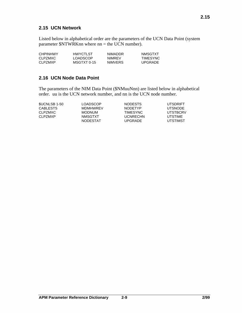
2.15 UCN Network
Listed below in alphabetical order are the parameters of the UCN Data Point (systemparameter $NTWRKnn where nn = the UCN number).
CHPINHWY HWYCTLST NIMADDR NMSGTXTCLPZMXC LOADSCOP NIMREV TIMESYNCCLPZMXP MSGTXT 0-15 NIMVERS UPGRADE
2.16 UCN Node Data Point
The parameters of the NIM Data Point ($NMuuNnn) are listed below in alphabeticalorder. uu is the UCN network number, and nn is the UCN node number.
$UCNLSB 1-50 LOADSCOP NODESTS UTSDRIFTCABLESTS MDMHWREV NODETYP UTSNODECLPZMXC MODNUM TIMESYNC UTSTBCRVCLPZMXP NMSGTXT UCNRECHN UTSTIME
NODESTAT UPGRADE UTSTIMST

APM Parameter Reference Dictionary 2-10 2/99
APM Parameter Reference Dictionary 3-1 2/99
3
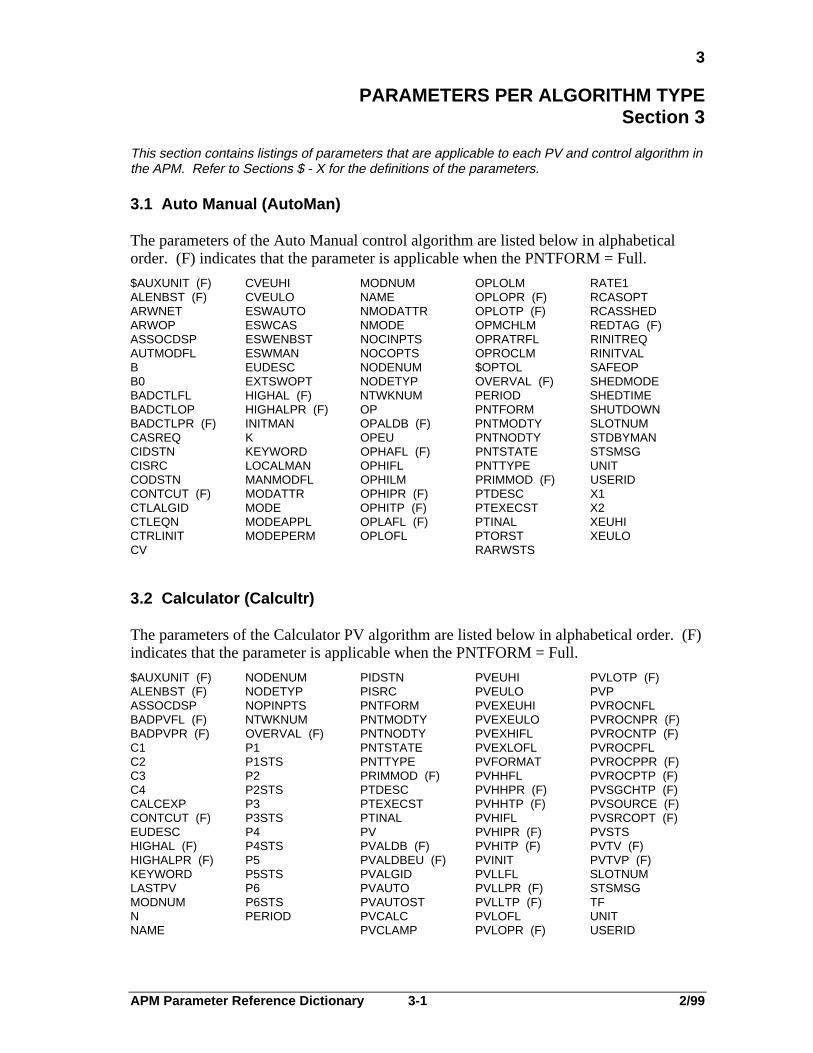
PARAMETERS PER ALGORITHM TYPESection 3
This section contains listings of parameters that are applicable to each PV and control algorithm inthe APM. Refer to Sections $ - X for the definitions of the parameters.
3.1 Auto Manual (AutoMan)
The parameters of the Auto Manual control algorithm are listed below in alphabeticalorder. (F) indicates that the parameter is applicable when the PNTFORM = Full.
$AUXUNIT (F) CVEUHI MODNUM OPLOLM RATE1ALENBST (F) CVEULO NAME OPLOPR (F) RCASOPTARWNET ESWAUTO NMODATTR OPLOTP (F) RCASSHEDARWOP ESWCAS NMODE OPMCHLM REDTAG (F)ASSOCDSP ESWENBST NOCINPTS OPRATRFL RINITREQAUTMODFL ESWMAN NOCOPTS OPROCLM RINITVALB EUDESC NODENUM $OPTOL SAFEOPB0 EXTSWOPT NODETYP OVERVAL (F) SHEDMODEBADCTLFL HIGHAL (F) NTWKNUM PERIOD SHEDTIMEBADCTLOP HIGHALPR (F) OP PNTFORM SHUTDOWNBADCTLPR (F) INITMAN OPALDB (F) PNTMODTY SLOTNUMCASREQ K OPEU PNTNODTY STDBYMANCIDSTN KEYWORD OPHAFL (F) PNTSTATE STSMSGCISRC LOCALMAN OPHIFL PNTTYPE UNITCODSTN MANMODFL OPHILM PRIMMOD (F) USERIDCONTCUT (F) MODATTR OPHIPR (F) PTDESC X1CTLALGID MODE OPHITP (F) PTEXECST X2CTLEQN MODEAPPL OPLAFL (F) PTINAL XEUHICTRLINIT MODEPERM OPLOFL PTORST XEULOCV RARWSTS
3.2 Calculator (Calcultr)
The parameters of the Calculator PV algorithm are listed below in alphabetical order. (F)indicates that the parameter is applicable when the PNTFORM = Full.
$AUXUNIT (F) NODENUM PIDSTN PVEUHI PVLOTP (F)ALENBST (F) NODETYP PISRC PVEULO PVPASSOCDSP NOPINPTS PNTFORM PVEXEUHI PVROCNFLBADPVFL (F) NTWKNUM PNTMODTY PVEXEULO PVROCNPR (F)BADPVPR (F) OVERVAL (F) PNTNODTY PVEXHIFL PVROCNTP (F)C1 P1 PNTSTATE PVEXLOFL PVROCPFLC2 P1STS PNTTYPE PVFORMAT PVROCPPR (F)C3 P2 PRIMMOD (F) PVHHFL PVROCPTP (F)C4 P2STS PTDESC PVHHPR (F) PVSGCHTP (F)CALCEXP P3 PTEXECST PVHHTP (F) PVSOURCE (F)CONTCUT (F) P3STS PTINAL PVHIFL PVSRCOPT (F)EUDESC P4 PV PVHIPR (F) PVSTSHIGHAL (F) P4STS PVALDB (F) PVHITP (F) PVTV (F)HIGHALPR (F) P5 PVALDBEU (F) PVINIT PVTVP (F)KEYWORD P5STS PVALGID PVLLFL SLOTNUMLASTPV P6 PVAUTO PVLLPR (F) STSMSGMODNUM P6STS PVAUTOST PVLLTP (F) TFN PERIOD PVCALC PVLOFL UNITNAME PVCLAMP PVLOPR (F) USERID

APM Parameter Reference Dictionary 3-2 2/99
3.3
3.3 Data Acquisition (DataAcq)
The parameters of the Data Acquisition PV algorithm are listed below in alphabeticalorder. (F) indicates that the parameter is applicable when the PNTFORM = Full.
$AUXUNIT (F) NTWKNUM PV PVHHFL PVROCNPR (F)ALENBST (F) OVERVAL (F) PVALDB (F) PVHHPR (F) PVROCNTP (F)ASSOCDSP P1 PVALDBEU (F) PVHHTP (F) PVROCPVFLBADPVFL (F) P1STS PVALGID PVHIFL PVROCPPR (F)BADPVPR (F) PERIOD PVAUTO PVHIPR (F) PVROVPTP (F)CONCUT (F) PIDSTN PVAUTOST PVHITP (F) PVSGCHTP (F)EUDESC PISRC PVCALC PVINIT PVSOURCE (F)HIGHAL (F) PNTFORM PVCLAMP PVLLFL PVSRCOPT (F)HIGHALPR (F) PNTMODTY PVEUHI PVLLPR (F) PVSTSKEYWORD PNTNODTY PVEULO PVLLTP (F) PVTV (F)LASTPV PNTSTATE PVEXEUHI PVLOFL PVTVP (F)MODNUM PNTTYPE PVEXEULO PVLOPR (F) SLOTNUMNAME PRIMMOD (F) PVEXHIFL PVLOTP (F) STSMSGNODENUM PTDESC PVEXLOFL PVP TFNODETYP PTEXECST PVFORMAT PVROCNFL UNITNOPINPTS PTINAL USERID
3.4 Flow Compensation (FlowComp)
The parameters of the Flow Compensation PV algorithm are listed below in alphabeticalorder. (F) indicates that the parameter is applicable when the PNTFORM = Full.
$AUXUNIT (F) MODNUM PTEXECST PVHHTP (F) PVSRCOPT (F)ALENBST (F) NAME PTINAL PVHIFL PVSTSASSOCDSP NODENUM PV PVHIPR (F) PVTV (F)BADPVFL (F) NODETYP PVALDB (F) PVHITP PVTVP (F)BADPVPR (F) NOPINPTS PVALDBEU (F) PVINIT QC NTWKNUM PVALGID PVLLFL QSTSC1 OVERVAL (F) PVAUTO PVLLPR (F) RGC2 P PVAUTOST PVLLTP (F) RPCOMPHILM PERIOD PVCALC PVOFL RQCOMPLOLM P0 PVCHAR PVLOPR (F) RTCOMPTERM PIDSTN PVCLAMP PVLOTP (F) RXCONTCUT (F) PISRC PVEQN PVP SLOTNUMEUDESC PNTFORM PVEUHI PVROCNFL STSMSGF PNTMODTY PVEULO PVROCNPR (F) TFSTS PNTNODTY PVEXEUHI PVROCNTP (F) T0G PNTSTATE PVEXEULO PVROCPFL TFGSTS PNTTYPE PVEXHIFL PVROCPPR (F) TSTSHIGHAL (F) PRIMMOD (F) PVEXLOFL PVROCPTP (F) UNITHIGHALPR (F) PSTS PVFORMAT PVSGCHTP (F) USERIDKEYWORD PTDESC PVHHFL PVSOURCE (F) XLASTPV PVHHPR (F) XSTS

APM Parameter Reference Dictionary 3-3 2/99
3.5
3.5 General Linearization (GenLin)
The parameters of the General Linearization PV algorithm are listed below inalphabetical order. (F) indicates that the parameter is applicable when the PNTFORM =Full.
$AUXUNIT (F) IN12 OUT12 PVAUTOST PVLOPR (F)ALENBST (F) KEYWORD OVERVAL (F) PVCALC PVLOTP (F)ASSOCDSP LASTPV P1 PVCLAMP PVPBADPVFL (F) MODNUM P1STS PVEUHI PVROCNFLBADVPR (F) NAME PERIOD PVEULO PVROCNPR (F)CONTCUT (F) NODENUM PIDSTN PVEXEUHI PVROCNTP (F)EUDESC NODETYP PISRC PVEXEULO PVROCPFLHIGHAL (F) NOPINPTS PNTFORM PVEXHIFL PVROCPPR (F)HIGHALPR (F) NTWKNUM PNTMODTY PVEXLOFL PVROCPTP (F)IN0 OUT0 PNTNODTY PVFORMAT PVSGCHTP (F)IN1 OUT1 PNTSTATE PVHHFL PVSOURCE (F)IN2 OUT2 PNTTYPE PVHHPR (F) PVSRCOPT (F)IN3 OUT3 PRIMMOD (F) PVHHTP (F) PVSTSIN4 OUT4 PTDESC PVHIFL PVTV (F)IN5 OUT5 PTEXECST PVHIPR (F) PVTVP (F)IN6 OUT6 PTINAL PVHITP (F) SEGTOTIN7 OUT7 PV PVINIT SLOTNUMIN8 OUT8 PVAUTO PVLLFL STSMSGIN9 OUT9 PVALDB (F) PVLLPR (F) TFIN10 OUT10 PVALDBEU (F) PVLLTP (F) UNITIN11 OUT11 PVALGID PVLOFL USERID
3.6 High-Low Average (HiLoAvg)
The parameters of the High-Low Average PV algorithm are listed below in alphabeticalorder. (F) indicates that the parameter is applicable when the PNTFORM = Full.
$AUXUNIT (F) NODETYP PNTFORM PVEULO PVPALENBST (F) NOPINPTS PNTMODTY PVEXEUHI PVROCNFLASSOCDSP NTWKNUM PNTNODTY PVEXEULO PVROCNPR (F)BADPVFL (F) OVERVAL (F) PNTSTATE PVEXHIFL PVROCNTP (F)BADPVPR (F) P1 PNTTYPE PVEXLOFL PVROCPFLCONTCUT (F) P1STS PRIMMOD (F) PVFORMAT PVROCPPR (F)EUDESC P2 PTDESC PVHHFL PVROCPTP (F)FORCE P2STS PTEXECST PVHHPR (F) PVSGCHTP (F)FRCPERM P3 PTINAL PVHHTP (F) PVSOURCE (F)FSELIN P3STS PV PVHIFL PVSRCOPT (F)HIGHAL (F) P4 PVALDB (F) PVHIPR (F) PVSTSHIGHALPR (F) P4STS PVALDBEU (F) PVHITP (F) PVTV (F)KEYWORD P5 PVALGID PVINIT PVTVP (F)LASTPV P5STS PVAUTO PVLLFL SELINPMODNUM P6 PVAUTOST PVLLPR (F) SLOTNUMN P6STS PVCALC PVLLTP (F) STSMSGNAME PERIOD PVCLAMP PVLOFL TFNMIN PIDSTN PVEQN PVLOPR (F) UNITNODENUM PISRC PVEUHI PVLOTP (F) USERID

APM Parameter Reference Dictionary 3-4 2/99
3.7
3.7 Incremental Summer (IncrSum)
The parameters of the Incremental Summer control algorithm are listed below inalphabetical order. (F) indicates that the parameter is applicable when the PNTFORM =Full.
$AUXUNIT (F) ESWCAS MODNUM OPLOLM RCASOPTALENBST (F) ESWENBST NAME OPLOPR (F) RCASSHEDARWNET ESWMAN NMODATTR OPLOTP (F) REDTAG (F)ARWOP EUDESC NMODE OPMCHLM RINITREQASSOCDSP EXTSWOPT NOCINPTS OPRATRFL RINITVALAUTMODFL HIGHAL (F) NOCOPTS OPROCLM SAFEOPBADCTLFL HIGHALPR (F) NODENUM $OPTOL SHEDMODEBADCTLPR (F) INITMAN NODETYP OVERVAL (F) SHEDTIMECASREQ K1 NTWKNUM PERIOD SHUTDOWNCIDSTN K2 OP PNTFORM SLOTNUMCISRC K3 OPALDB (F) PNTMODTY STDBYMANCODSTN K4 OPEU PNTNODTY STSMSGCONTCUT (F) KEYWORD OPHAFL (F) PNTSTATE UNITCTLALGID LOCALMAN OPHIFL PNTTYPE USERIDCTRLINIT M OPHILM PRIMMOD (F) X1CV MANMODFL OPHIPR (F) PTDESC X2CVEUHI MODATTR OPHITP (F) PTEXECST X3CVEULO MODE OPLAFL (F) PTINAL X4DELCV MODEAPPL OPLOFL PTORST XEUHIESWAUTO MODEPERM RARWSTS XEULO
3.8 Middle-of-3 (MidOf3)
The parameters of the Middle-Of-3 PV algorithm are listed below in alphabetical order.(F) indicates that the parameter is applicable when the PNTFORM = Full.
$AUXUNIT (F) OVERVAL (F) PTEXECST PVFORMAT PVROCNPR (F)ALENBST (F) P1 PTINAL PVHHFL PVROCNTP (F)ASSOCDSP P1STS PV PVHHPR (F) PVROCPFLBADPVFL (F) P2 PVALDB (F) PVHHTP (F) PVROCPPR (F)BADPVPR (F) P2STS PVALDBEU (F) PVHIFL PVROCPTP (F)CONTCUT (F) P3 PVALGID PVHIPR (F) PVSGCHTP (F)EUDESC P3STS PVAUTO PVHITP (F) PVSOURCE (F)HIGHAL (F) PERIOD PVAUTOST PVINIT PVSRCOPT (F)HIGHALPR (F) PIDSTN PVCALC PVLLFL PVSTSKEYWORD PISRC PVCLAMP PVLLPR (F) PVTV (F)LASTPV PNTFORM PVEQN PVLLTP (F) PVTVP (F)MODNUM PNTMODTY PVEUHI PVLOFL SELINPNAME PNTNODTY PVEULO PVLOPR (F) SLOTNUMNODENUM PNTSTATE PVEXEUHI PVLOTP (F) STSMSGNODETYP PNTTYPE PVEXEULO PVP TFNOPINPTS PRIMMOD (F) PVEXHIFL PVROCNFL UNITNTWKNUM PTDESC PVEXLOFL USERID

APM Parameter Reference Dictionary 3-5 2/99
3.9
3.9 Override Selector (ORSel)
The parameters of the Override Selector control algorithm are listed below in alphabeticalorder. (F) indicates that the parameter is applicable when the PNTFORM = Full.
$AUXUNIT (F) CTRLINIT MODNUM OPLOPR (F) RCASOPTALENBST (F) CV NAME OPLOTP (F) RCASSHEDARWNET CVEUHI NMODATTR OPMCHLM REDTAG (F)ARWOP CVEULO NMODE OPRATRFL RINITREQASSOCDSP ESWAUTO NOCINPTS OPROCLM RINITVALAUTMODFL ESWCAS NOCOPTS $OPTOL SAFEOPBADCTLFL ESWENBST NODENUM OROFFSET SELXINPBADCTLOP ESWMAN NODETYP OROPT SHEDMODEBADCTLPR (F) EUDESC NTWKNUM OVERVAL (F) SHEDTIMEBYPASS EXTSWOPT OP PERIOD SHUTDOWNBYPASSX1 HIGHAL (F) OPALDB (F) PNTFORM SLOTNUMBYPASSX2 HIGHALPR (F) OPEU PNTMODTY STDBYMANBYPASSX3 INITMAN OPHAFL (F) PNTNODTY STSMSGBYPASSX4 KEYWORD OPHIFL PNTSTATE UNITCASREQ LOCALMAN OPHILM PNTTYPE USERIDCIDSTN M OPHIPR (F) PRIMMOD (F) X1CISRC MANMODFL OPHITP (F) PTDESC X2CODSTN MODE OPLAFL (F) PTEXECST X3CONTCUT (F) MODEAPPL OPLOFL PTINAL X4CTALGID MODATTR OPLOLM PTORST XEUHICTLEQN MODEPERM RARWSTS XEULO
APM Parameter Reference Dictionary 3-6 2/99
3.10
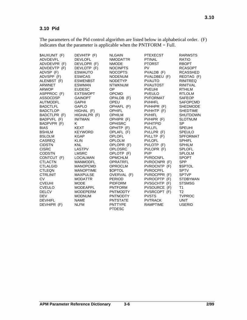
3.10 Pid
The parameters of the Pid control algorithm are listed below in alphabetical order. (F)indicates that the parameter is applicable when the PNTFORM = Full.
$AUXUNIT (F) DEVHITP (F) NLGAIN PTEXECST RARWSTSADVDEVFL DEVLOFL NMODATTR PTINAL RATIOADVDEVPR (F) DEVLOPR (F) NMODE PTORST RBOPTADVDEVTP (F) DEVLOTP (F) NOCINPTS PV RCASOPTADVSP (F) ESWAUTO NOCOPTS PVALDB (F) RCASSHEDADVSPP (F) ESWCAS NODENUM PVALDBEU (F) REDTAG (F)ALENBST (F) ESWENBST NODETYP PVAUTO RINITREQARWNET ESWMAN NTWKNUM PVAUTOST RINITVALARWOP EUDESC OP PVEUHI RTHILMASPPROC (F) EXTSWOPT OPCMD PVEULO RTLOLMASSOCDSP GAINOPT OPALDB (F) PVFORMAT SAFEOPAUTMODFL GAPHI OPEU PVHHFL SAFOPCMDBADCTLFL GAPLO OPHAFL (F) PVHHPR (F) SHEDMODEBADCTLOP HIGHAL (F) OPHIFL PVHHTP (F) SHEDTIMEBADCTLPR (F) HIGHALPR (F) OPHILM PVHIFL SHUTDOWNBADPVFL (F) INITMAN OPHIPR (F) PVHIPR (F) SLOTNUMBADPVPR (F) K OPHISRC PVHITPID SPBIAS KEXT OPHITP (F) PVLLFL SPEUHIBSHILM KEYWORD OPLAFL (F) PVLLPR (F) SPEULOBSLOLM KGAP OPLOFL PVLLTP (F) SPFORMATCASREQ KLIN OPLOLM PVLOFL SPHIFLCIDSTN KNL OPLOPR (F) PVLOTP (F) SPHILMCISRC LASTPV OPLOSRC PVLOPR (F) SPLOFLCODSTN LMSRC OPLOTP (F) PVP SPLOLMCONTCUT (F) LOCALMAN OPMCHLM PVROCNFL SPOPTCTLACTN MANMODFL OPRATRFL PVROCNPR (F) SPPCTLALGID MANOPCMD OPROCLM PVROCNTP (F) $SPTOLCTLEQN MANOPTIME $OPTOL PVROCPFL SPTVCTRLINIT MAXPULSE OVERVAL (F) PVROCPPR (F) SPTVPCV MODATTR PERIOD PVROCPTP (F) STDBYMANCVEUHI MODE PIDFORM PVSGCHTP (F) STSMSGCVEULO MODEAPPL PNTFORM PVSOURCE (F) T1DELCV MODEPERM PNTMODTY PVSRCOPT (F) T2DEV MODNUM PNTNODTY PVSTS TVPROCDEVHIFL NAME PNTSTATE PVTRACK UNITDEVHIPR (F) NLFM PNTTYPE RAMPTIME USERID
PTDESC
APM Parameter Reference Dictionary 3-7 2/99
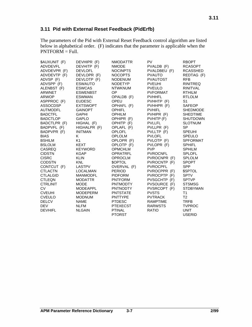
3.11
3.11 Pid with External Reset Feedback (PidErfb)
The parameters of the Pid with External Reset Feedback control algorithm are listedbelow in alphabetical order. (F) indicates that the parameter is applicable when thePNTFORM = Full.
$AUXUNIT (F) DEVHIPR (F) NMODATTR PV RBOPTADVDEVFL DEVHITP (F) NMODE PVALDB (F) RCASOPTADVDEVPR (F) DEVLOFL NOCINPTS PVALDBEU (F) RCASSHEDADVDEVTP (F) DEVLOPR (F) NOCOPTS PVAUTO REDTAG (F)ADVSP (F) DEVLOTP (F) NODENUM PVAUTOST RFBADVSPP (F) ESWAUTO NODETYP PVEUHI RINITREQALENBST (F) ESWCAS NTWKNUM PVEULO RINITVALARWNET ESWENBST OP PVFORMAT RTHILMARWOP ESWMAN OPALDB (F) PVHHFL RTLOLMASPPROC (F) EUDESC OPEU PVHHTP (F) S1ASSOCDSP EXTSWOPT OPHAFL (F) PVHHPR (F) SAFEOPAUTMODFL GAINOPT OPHIFL PVHIFL SHEDMODEBADCTFL GAPHI OPHILM PVHIPR (F) SHEDTIMEBADCTLOP GAPLO OPHIPR (F) PVHITP (F) SHUTDOWNBADCTLPR (F) HIGHAL (F) OPHITP (F) PVLLFL SLOTNUMBADPVFL (F) HIGHALPR (F) OPLAFL (F) PVLLPR (F) SPBADPVPR (F) INITMAN OPLOFL PVLLTP (F) SPEUHIBIAS K OPLOLM PVLOFL SPEULOBSHILM K1 OPLOPR (F) PVLOTP (F) SPFORMATBSLOLM KEXT OPLOTP (F) PVLOPR (F) SPHIFLCASREQ KEYWORD OPMCHLM PVP SPHILMCIDSTN KGAP OPRATRFL PVROCNFL SPLOFLCISRC KLIN OPROCLM PVROCNPR (F) SPLOLMCODSTN KNL $OPTOL PVROCNTP (F) SPOPTCONTCUT (F) LASTPV OVERVAL (F) PVROCPFL SPPCTLACTN LOCALMAN PERIOD PVROCPPR (F) $SPTOLCTLALGID MANMODFL PIDFORM PVROCPTP (F) SPTVCTLEQN MODATTR PNTFORM PVSGCHTP (F) SPTVPCTRLINIT MODE PNTMODTY PVSOURCE (F) STSMSGCV MODEAPPL PNTNODTY PVSRCOPT (F) STDBYMANCVEUHI MODEPERM PNTSTATE PVSTS T1CVEULO MODNUM PNTTYPE PVTRACK T2DELCV NAME PTDESC RAMPTIME TRFBDEV NLFM PTEXECST RARWSTS TVPROCDEVHIFL NLGAIN PTINAL RATIO UNIT
PTORST USERID

APM Parameter Reference Dictionary 3-8 2/99
3.12
3.12 Pid with Feed Forward (PidFf)
The parameters of the Pid with Feed Forward control algorithm are listed below inalphabetical order. (F) indicates that the parameter is applicable when the PNTFORM =Full.
$AUXUNIT (F) DEVHIPR (F) NLGAIN PTORST RARWSTSADVDEVFL DEVHITP (F) NMODATTR PV RATIOADVDEVPR (F) DEVLOFL NMODE PVALDB (F) RBOPTADVDEVTP DEVLOPR (F) NOCINPTS PVALDBEU (F) RCASOPTADVSP (F) DEVLOTP (F) NOCOPTS PVAUTO RCASSHEDADVSPP (F) ESWAUTO NODENUM PVAUTOST REDTAG (F)ALENBST (F) ESWCAS NODETYP PVEUHI RINITREQARWNET ESWENBST NTWKNUM PVEULO RINITVALARWOP ESWMAN OP PVFORMAT RTHILMASPPROC (F) EUDESC OPALDB (F) PVHHFL RTLOLMASSOCDSP EXTSWOPT OPEU PVHHPR (F) SAFEOPAUTMODFL FF OPHAFL (F) PVHHTP (F) SHEDMODEBADCTLFL FFOPT OPHIFL PVHIFL SHEDTIMEBADCTLOP GAINOPT OPHILM PVHIPR (F) SHUTDOWNBADCTLPR (F) GAPHI OPHIPR (F) PVHITP (F) SLOTNUMBADPVFL (F) GAPLO OPHITP (F) PVLLFL SPBADPVPR (F) HIGHAL (F) OPLAFL (F) PVLLPR (F) SPEUHIBFF HIGHALPR (F) OPLOFL PVLLTP (F) SPEULOBIAS INITMAN OPLOLM PVLOFL SPFORMATBSHILM K OPLOPR (F) PVLOTP (F) SPHIFLBSLOLM KEXT OPLOTP (F) PVLOPR (F) SPHILMCASREQ KEYWORD OPMCHLM PVP SPLOFLCIDSTN KFF OPRATRFL PVROCNFL SPLOLMCISRC KGAP OPROCLM PVROCNPR (F) SPOPTCODSTN KLIN $OPTOL PVROCNTP (F) SPPCONTCUT (F) KNL OVERVAL (F) PVROCPFL $SPTOLCTLACTN LASTPV PERIOD PVROCPPR (F) SPTVCTLALGID LOCALMAN PIDFORM PVROCPTP (F) SPTVPCTLEQN MANMODFL PNTFORM PVSGCHTP (F) STDBYMANCTRLINIT MODATTR PNTMODTY PVSOURCE (F) STSMSGCV MODE PNTNODTY PVSRCOPT (F) T1CVEUHI MODEAPPL PNTSTATE PVSTS T2CVEULO MODEPERM PNTTYPE PVTRACK TVPROCDELCV MODNUM PTDESC RAMPTIME UNITDEV NAME PTEXECST USERIDDEVHIFL NLFM PTINAL

APM Parameter Reference Dictionary 3-9 2/99
3.13
3.13 PID with Position Proportional (PidPosPr)
The parameters of the PID Position Proportional control algorithm are listed below inalphabetical order.
$AUXUNIT (F) DEVHIPR (F) MODATTR PVALDBEU (F) RATIOADVDEVFL DEVHITP (F) MODE PVAUTO RBOPTADVDEVPR (F) DEVLOFL MODEAPPL PVAUTOST RCASOPTADVDEVTP (F) DEVLOPR (F) MODEPERM PVEUHI RCASSHEDADVSP (F) DEVLOTP (F) MODNUM PVEULO REDTAG (F)ADVSPP (F) ESWAUTO NAME PVFORMAT RINITREQALENBST (F) ESWCAS NLFM PVHHFL RINITVALARWNET ESWENBST NLGAIN PVHHPR (F) RPARWOP ESWMAN NMODATTR PVHHTP (F) RTASPPROC (F) EUDESC NMODE PVHIFL RTHILMASSOCDSP EXTSWOPT NOCINPTS PVHIPR (F) RTLOLMAUTMODFL GAINOPT NOCOPTS PVHITP (F) SAFEOPCMDBADCTLFL GAPHI NODENUM PVLLFL SHEDMODEBADCTLOP GAPLO NODETYP PVLLPR (F) SHEDTIMEBADCTLPR (F) HIGHAL (F) NTWKNUM PVLLTP (F) SHUTDOWNBADPVFL (F) HIGHALPR (F) OPCMD PVLOFL SLOTNUMBADPVPR (F) INITMAN OPHIFL PVLOPR (F) SPBADPVR (F) K OPHISRC PVLOTP (F) SPEUHIBIAS K1 OPLOFL PVP SPEULOBSHILM KEXT OPLOSRC PVROCNFL SPFORMATBSLOLM KEYWORD OVERVAL (F) PVROCNPR (F) SPHIFLCASREQ KGAP PERIOD PVROCNTP (F) SPHILMCIDSTN KLIN PIDFORM PVROCPFL SPLOFLCISRC KNL PNTFORM PVROCPPR (F) SPLOLMCODSTN LASTPV PNTMODTY PVROCPTP (F) SPOPTCONTCUT (F) LMSRC PNTNODTY PVSGCHTP (F) SPPCTLACTN LOCALMAN PNTSTATE PVSOURCE (F) $SPTOLCTLALGID LOWERTIM PNTTYPE PVSRCOPT (F) SPTVCTLEQN LOWRDSTN PRIMMOD (F) PVSTS SPTVPCTRLINIT LOWRRATE PTDESC PVTRACK STDBYMANCYCLETIM MANMODFL PTEXECST RAISDSTN STSMSGDEADBAND MANOPCMD PTINAL RAISETIM T1DEADTIME MANOPTIM PTORST RAISRATE T2DELCV MAXPULSE PV RAMPTIME TVPROCDEV MINPULSE PVALDB (F) RARWSTS UNITDEVHIFL USERID

APM Parameter Reference Dictionary 3-10 2/99
3.14
3.14 Position Proportional (PosProp)
The parameters of the Position Proportional control algorithm are listed below inalphabetical order. (F) indicates that the parameter is applicable when the PNTFORM =Full.
$AUXUNIT (F) DEVHITP (F) MODNUM PVAUTOST RAMPTIMEADVDEVFL DEVLOFL NAME PVEUHI RARWSTSADVDEVPR (F) DEVLOPR (F) NMODATTR PVEULO RCASOPTADVDEVTP (F) DEVLOTP (F) NMODE PVFORMAT RCASSHEDADVSP (F) ESWAUTO NOCINPTS PVHHFL REDTAG (F)ADVSPP (F) ESWCAS NOCOPTS PVHHPR (F) RINITREQALENBST (F) ESWENBST NODENUM PVHHTP (F) RINITVALARWNET ESWMAN NODETYP PVHIFL RPARWOP EUDESC NTWKNUM PVHIPR (F) RTASPPROC (F) EXTSWOPT OPCMD PVHITP (F) SAFOPCMDASSOCDSP HIGHAL (F) OPHIFL PVLLFL SHEDMODEAUTMODFL HIGHALPR (F) OPHISRC PVLLPR (F) SHEDTIMEBADCTLFL INITMAN OPLOFL PVLLTP (F) SHUTDOWNBADCTLOP KEYWORD OPLOSRC PVLOFL SLOTNUMBADCTLPR (F) LASTPV OVERVAL (F) PVLOPR (F) SPBADPVFL (F) LMSRC PERIOD PVLOTP (F) SPEUHIBADPVR (F) LOCALMAN PNTFORM PVP SPEULOCASREQ LOWERTIM PNTMODTY PVROCNFL SPFORMATCIDSTN LOWRDSTN PNTNODTY PVROCNPR (F) SPHIFLCISRC LOWRRATE PNTSTATE PVROCNTP (F) SPHILMCODSTN LTIMHILM PNTTYPE PVROCPFL SPLOFLCONTCUT (F) MANMODFL PRIMMOD (F) PVROCPPR (F) SPLOLMCTLALGID MANOPCMD PTDESC PVROCPTP (F) SPOPTCTRLINIT MANOPTIM PTEXECST PVSGCHTP (F) SPPCYCLETIM MAXPULSE PTINAL PVSOURCE (F) $SPTOLDEADBAND MINPULSE PTORST PVSRCOPT (F) SPTVDEADTIME MODATTR PV PVSTS SPTVPDEV MODE PVALDB (F) RAISDSTN STDBYMANDEVHIFL MODEAPPL PVALDBEU (F) RAISETIM STSMSGDEVHIPR (F) MODEPERM PVAUTO RAISRATE TVPROC
UNITUSERID

APM Parameter Reference Dictionary 3-11 2/99
3.15
3.15 Ramp Soak (RampSoak)
The parameters of the Ramp Soak control algorithm are listed below in alphabeticalorder. (F) indicates that the parameter is applicable when the PNTFORM = Full.
$AUXUNIT (F) DEVLOPR (F) NTWKNUM RARWSTS SOAKT3ADVDEVFL DEVLOTP (F) NXTSOAKV RATE1 SOAKT4ADVDEVPR (F) ESWAUTO OP RATE2 SOAKT5ADVDEVTP (F) ESWCAS OPEU RATE3 SOAKT6ADVSP (F) ESWENBST OPHIFL RATE4 SOAKT7ADVSPP (F) ESWMAN OPHILM RATE5 SOAKT8ALENBST (F) EUDESC OPLOFL RATE6 SOAKT9ARWNET EXTSWOPT OPLOLM RATE7 SOAKT10ARWOP HIGHAL (F) OPMCHLM RATE8 SOAKT11ASPPROC (F) HIGHALPR (F) OPRATRFL RATE9 SOAKT12ASSOCDSP HOLDCMD OPROCLM RATE10 SOAKV1AUTMODFL INITMAN $OPTOL RATE11 SOAKV2BADCTLFL KEYWORD OVERVAL (F) RATE12 SOAKV3BADCTLPR (F) LASTPV PERIOD REDTAG (F) SOAKV4CASREQ LOCALMAN PNTFORM REMSOAKT SOAKV5CIDSTN MANMODFL PNTMODTY RINITREQ SOAKV6CISRC MODATTR PNTNODTY RINITVAL SOAKV7CODSTN MODE PNTSTATE S1 SOAKV8CONTCUT (F) MODEAPPL PNTTYPE S1BGNTIM SOAKV9CTLALGID MODEPERM PRIMMOD S1ENDTIM SOAKV10CTRLINIT MODNUM PTDESC S1SEGID SOAKV11CURSEGID MXRMPDEV‘ PTEXECST S2 SOAKV12CV MXSOKDEV PTINAL S2BGNTIM SPCVEUHI NAME PTORST S2ENDTIM SPPCVEULO NMODATTR PV S2SEGID STDBYMANCYCLEOPT NMODE PVEUHI SAFEOP STSMSGDEV NOCINPTS PVEULO SEGTYPE TVPROCDEVHIPR (F) NOCOPTS PVFORMAT SHUTDOWN UNITDEVHIFL NODENUM PVP SLOTNUMDEVHITP (F) NODETYP PVSTS SOAKT1DEVLOFL NORSSEQ RAMPTIME SOAKT2
APM Parameter Reference Dictionary 3-12 2/99
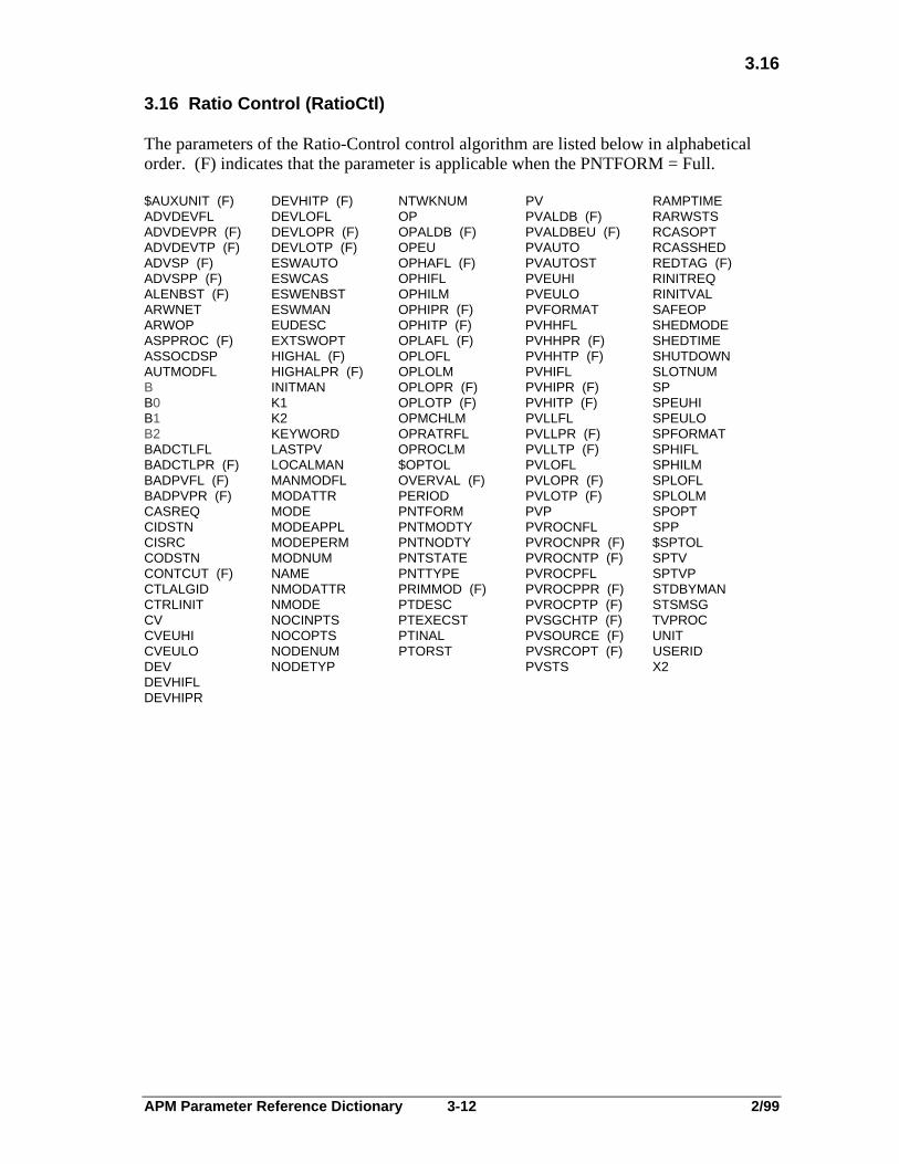
3.16
3.16 Ratio Control (RatioCtl)
The parameters of the Ratio-Control control algorithm are listed below in alphabeticalorder. (F) indicates that the parameter is applicable when the PNTFORM = Full.
$AUXUNIT (F) DEVHITP (F) NTWKNUM PV RAMPTIMEADVDEVFL DEVLOFL OP PVALDB (F) RARWSTSADVDEVPR (F) DEVLOPR (F) OPALDB (F) PVALDBEU (F) RCASOPTADVDEVTP (F) DEVLOTP (F) OPEU PVAUTO RCASSHEDADVSP (F) ESWAUTO OPHAFL (F) PVAUTOST REDTAG (F)ADVSPP (F) ESWCAS OPHIFL PVEUHI RINITREQALENBST (F) ESWENBST OPHILM PVEULO RINITVALARWNET ESWMAN OPHIPR (F) PVFORMAT SAFEOPARWOP EUDESC OPHITP (F) PVHHFL SHEDMODEASPPROC (F) EXTSWOPT OPLAFL (F) PVHHPR (F) SHEDTIMEASSOCDSP HIGHAL (F) OPLOFL PVHHTP (F) SHUTDOWNAUTMODFL HIGHALPR (F) OPLOLM PVHIFL SLOTNUMB INITMAN OPLOPR (F) PVHIPR (F) SPB0 K1 OPLOTP (F) PVHITP (F) SPEUHIB1 K2 OPMCHLM PVLLFL SPEULOB2 KEYWORD OPRATRFL PVLLPR (F) SPFORMATBADCTLFL LASTPV OPROCLM PVLLTP (F) SPHIFLBADCTLPR (F) LOCALMAN $OPTOL PVLOFL SPHILMBADPVFL (F) MANMODFL OVERVAL (F) PVLOPR (F) SPLOFLBADPVPR (F) MODATTR PERIOD PVLOTP (F) SPLOLMCASREQ MODE PNTFORM PVP SPOPTCIDSTN MODEAPPL PNTMODTY PVROCNFL SPPCISRC MODEPERM PNTNODTY PVROCNPR (F) $SPTOLCODSTN MODNUM PNTSTATE PVROCNTP (F) SPTVCONTCUT (F) NAME PNTTYPE PVROCPFL SPTVPCTLALGID NMODATTR PRIMMOD (F) PVROCPPR (F) STDBYMANCTRLINIT NMODE PTDESC PVROCPTP (F) STSMSGCV NOCINPTS PTEXECST PVSGCHTP (F) TVPROCCVEUHI NOCOPTS PTINAL PVSOURCE (F) UNITCVEULO NODENUM PTORST PVSRCOPT (F) USERIDDEV NODETYP PVSTS X2DEVHIFLDEVHIPR

APM Parameter Reference Dictionary 3-13 2/99
3.17
3.17 Summer
The parameters of the Summer PV algorithm are listed below in alphabetical order. (F)indicates that the parameter is applicable when the PNTFORM = Full.
$AUXUNIT (F) MODNUM PERIOD PVCLAMP PVLOPR (F)ALENBST (F) NAME PISRC PVEQN PVLOTP (F)ASSOCDSP NODENUM PIDSTN PVEULO PVPBADPVFL (F) NODETYP PNTFORM PVEUHI PVROCNFLBADPVPR (F) NOPINPTS PNTMODTY PVEXEUHI PVROCNPR (F)C NTWKNUM PNTNODTY PVEXEULO PVROCNTP (F)C1 OVERVAL (F) PNTSTATE PVEXHIFL PVROCPFLC2 P1 PNTTYPE PVEXLOFL PVROCPPR (F)C3 P1STS PRIMMOD (F) PVFORMAT PVROCPTP (F)C4 P2 PTDESC PVHHFL PVSGCHTP (F)C5 P2STS PTEXECST PVHHPR (F) PVSOURCE (F)C6 P3 PTINAL PVHHTP (F) PVSRCOPT (F)CONTCUT P3STS PV PVHIFL PVSTSD P4 PVALDB (F) PVHIPR (F) PVTV (F)EUDESC P4STS PVALDBEU (F) PVHITP (F) PVTVP (F)HIGHAL (F) P5 PVALGID PVINIT SLOTNUMHIGHALPR (F) P5STS PVAUTO PVLLFL STSMSGKEYWORD P6 PVAUTOST PVLLPR (F) TFLASTPV P6STS PVCALC PVLLTP (F) UNITN PVLOFL USERID
3.18 Switch
The parameters of the Switch control algorithm are listed below in alphabetical order. (F)indicates that the parameter is applicable when the PNTFORM = Full.
$AUXUNIT (F) ESWCAS NOCINPTS OPROCLM S2ALENBST (F) ESWENBST NOCOPTS $OPTOL S3ARWNET ESWMAN NODENUM OVERVAL (F) S4ARWOP EUDESC NODETYP PERIOD SAFEOPASSOCDSP EXTSWOPT NTWKNUM PNTFORM SELXINPAUTMODFL HIGHAL (F) OP PNTMODTY SHEDMODEBADCTFL HIGHALPR (F) OPALDB (F) PNTNODTY SHEDTIMEBADCTLOP INITMAN OPEU PNTSTATE SHUTDOWNBADCTLPR (F) KEYWORD OPHAFL (F) PNTTYPE SLOTNUMCASREQ LOCALMAN OPHIFL PRIMMOD (F) STDBYMANCIDSTN M OPHILM PTDESC STSMSGCISRC MANMODFL OPHIPR (F) PTEXECST TRACKINGCODSTN MODATTR OPHITP (F) PTINAL UNITCONTCUT (F) MODE OPLAFL (F) PTORST USERIDCTLALGID MODEAPPL OPLOFL RARWSTS X1CTLEQN MODEPERM OPLOLM RCASOPT X2CTRLINIT MODNUM OPLOPR (F) RCASSHED X3CV NAME OPLOTP (F) REDTAG (F) X4CVEUHI NMODATTR OPMCHLM RINITREQ XEUHICVEULO NMODE OPRATRFL RINITVAL XEULOESWAUTO S1

APM Parameter Reference Dictionary 3-14 2/99
3.19
3.19 Totalizer (Totalizr)
The parameters of the Totalizer PV algorithm are listed below in alphabetical order. (F)indicates that the parameter is applicable when the PNTFORM = Full.
$AUXUNIT (F) LASTPV PNTTYPE PVEXLOFL PVROCPFLACCTYPE MODNUM PRIMMOD (F) PVFORMAT PVROCPPR (F)ALENBST (F) NAME PTDESC PVHHFL PVROCPTP (F)ASSOCDSP NODENUM PTEXECST PVHHPR (F) PVSGCHTP (F)AVDEV1FL NODETYP PTINAL PVHHTP (F) PVSOURCE (F)AVDEV1TP NOPINPTS PV PVHIFL PVSRCOPT (F)AVDEV2FL NTWKNUM PVALDB (F) PVHIPR (F) PVSTSAVDEV2TP OLDAV PVALDBEU (F) PVHITP (F) PVTV (F)AVTV OVERVAL (F) PVALGID PVINIT PVTVP (F)AVTVFL P1 PVAUTO PVLLFL RESETFLBADPVFL (F) P1STS PVAUTOST PVLLPR (F) RESETVALBADPVPR (F) P2 PVCALC PVLLTP (F) SLOTNUMC P2STS PVCLAMP PVLOFL STARTFLCOMMAND PERIOD PVEQN PVLOPR (F) STATECONTCUT (F) PIDSTN PVEUHI PVLOTP (F) STOPFLCUTOFFLM PISRC PVEULO PVP STSMSGEUDESC PNTFORM PVEXEUHI PVROCNFL TFHIGHAL (F) PNTMODTY PVEXEULO PVROCNPR (F) TIMEBASEHIGHALPR (F) PNTNODTY PVEXHIFL PVROCNTP (F) UNITKEYWORD PNTSTATE USERID
3.20 Variable Dead Time with Lead/Lag (VdtLdLag)
The parameters of the Variable Dead Time with Lead/Lag PV algorithm are listed belowin alphabetical order. (F) indicates that the parameter is applicable when the PNTFORM= Full.
$AUXUNIT (F) NAME PRIMMOD (F) PVEXLOFL PVROCNTP (F)ALENBST (F) NLOC PTDESC PVFORMAT PVROCPFLASSOCDSP NODENUM PTEXECST PVHHFL PVROCPPR (F)BADPVFL (F) NODETYP PTINAL PVHHPR (F) PVROCPTP (F)BADPVPR (F) NOPINPTS PV PVHHTP (F) PVSGCHTP (F)C NTWKNUM PVALDB (F) PVHIFL PVSOURCE (F)C1 OVERVAL (F) PVALDBEU (F) PVHIPR (F) PVSRCOPT (F)C2 P1 PVALGID PVHITP (F) PVSTSCONTCUT (F) P1STS PVAUTO PVINIT PVTV (F)CUTOFFLM P2 PVAUTOST PVLLFL PVTVP (F)D P2STS PVCALC PVLLPR (F) SLOTNUMD1 PERIOD PVCLAMP PVLLTP (F) STSMSGD2 PIDSTN PVEQN PVLOFL TDEUDESC PISRC PVEUHI PVLOPR (F) TFHIGHAL (F) PNTFORM PVEULO PVLOTP (F) TLDHIGHALPR (F) PNTMODTY PVEXEUHI PVP TLG1KEYWORD PNTNODTY PVEXEULO PVROCNFL TLG2LASTPV PNTSTATE PVEXHIFL PVROCNPR (F) UNITMODNUM PNTTYPE USERID
APM Parameter Reference Dictionary $-1 2/99
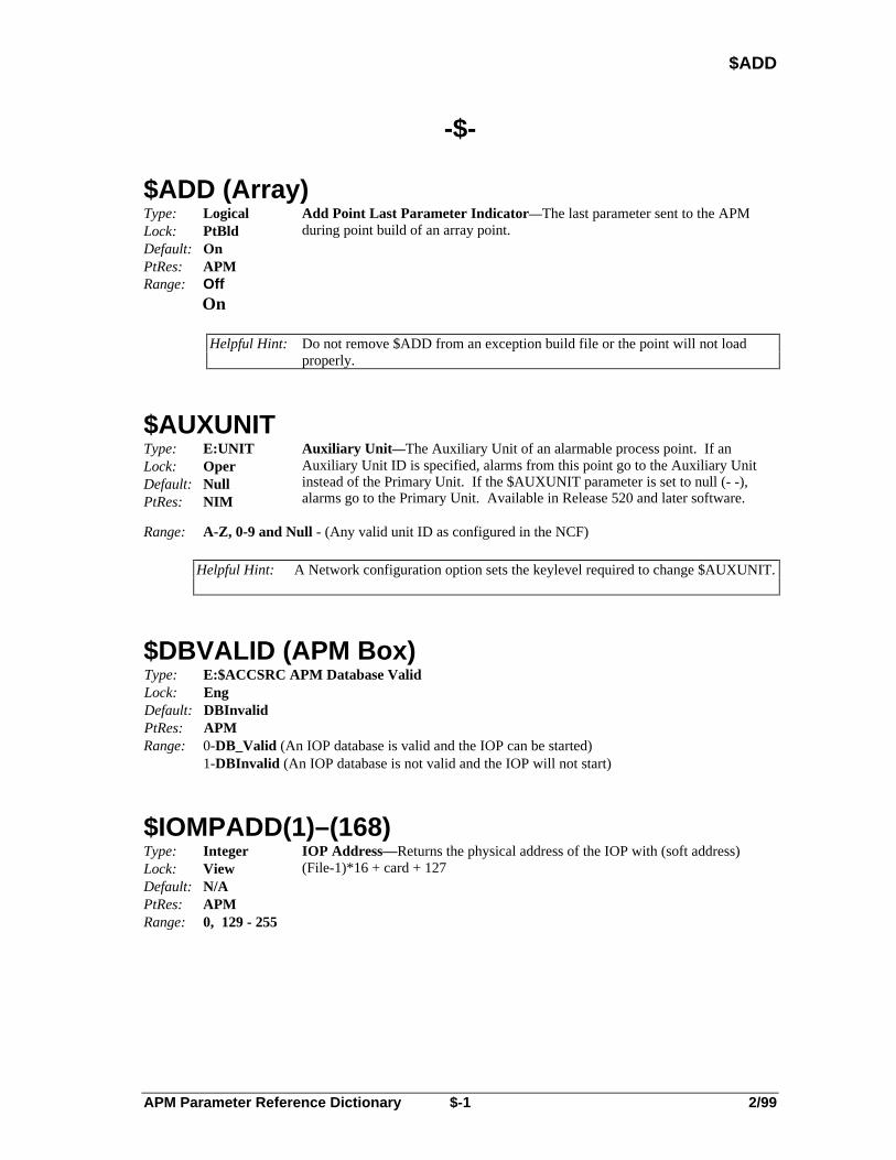
$ADD
-$-
$ADD (Array)Type: LogicalLock: PtBldDefault: OnPtRes: APM
Add Point Last Parameter Indicator—The last parameter sent to the APMduring point build of an array point.
Range: OffOn
Helpful Hint: Do not remove $ADD from an exception build file or the point will not loadproperly.
$AUXUNITType: E:UNITLock: OperDefault: NullPtRes: NIM
Auxiliary Unit—The Auxiliary Unit of an alarmable process point. If anAuxiliary Unit ID is specified, alarms from this point go to the Auxiliary Unitinstead of the Primary Unit. If the $AUXUNIT parameter is set to null (- -),alarms go to the Primary Unit. Available in Release 520 and later software.
Range: A-Z, 0-9 and Null - (Any valid unit ID as configured in the NCF)
Helpful Hint: A Network configuration option sets the keylevel required to change $AUXUNIT.
$DBVALID (APM Box)Type: E:$ACCSRC APM Database ValidLock: EngDefault: DBInvalidPtRes: APMRange: 0-DB_Valid (An IOP database is valid and the IOP can be started)
1-DBInvalid (An IOP database is not valid and the IOP will not start)
$IOMPADD(1)–(168)Type: IntegerLock: ViewDefault: N/APtRes: APM
IOP Address—Returns the physical address of the IOP with (soft address)(File-1)*16 + card + 127
Range: 0, 129 - 255

APM Parameter Reference Dictionary $-2 2/99
$OPTOL
$OPTOL (RegCtl, AO)
Type: Real (in Percent)
Lock: EngineerDefault: 0.0PtRes: APM
Output Tolerance Parameter Definition—Tolerance limit for a manuallyentered OP. The difference between a new OP and a current OP is comparedagainst $OPTOL. If the tolerance is violated in either a positive or negativedirection from the current value of the OP, operator confirmation is requiredbefore the value is stored. A value of 0.0 disables this check. An NaN or anegative value is not allowed.
Range: 0.0 to 106.9
$SPTOL (RegCtl)
Type: Real (inEngineeringUnits)
Lock: EngineerDefault: 0.0PtRes: APM
Setpoint Tolerance Parameter Definition—Tolerance limit for a manuallyentered SP. The difference between a new SP and a current SP is comparedagainst $SPTOL. If the tolerance is violated in either a positive or negativedirection from the current value of the SP, operator confirmation is requiredbefore the value is stored. A value of 0.0 disables this check. An NaN or anegative value is not allowed.
Range: >= 0.0
$UCNLSB(1)–(50)Type: RealLock: ViewDefault:PtRes: APM
Local UCN Communications Statistics
Range:
$UCNLSB(45) (NIM)Type: RealLock: ViewDefault: 0PtRes: APM, NIM
Local Statistics Block—The number of auto reconnects.
Range: ≤ 0

APM Parameter Reference Dictionary A-1 2/99
AB_DATA1
-A-
AB_DATA1 (SI - Array)Type: RealLock: EngDefault: NaNPtRes: APM
Auxiliary A-B Data 1— Specifies the Allen-Bradley PLC family type: 2.0, 3.0,or 5.0. Refer to the APM/HPM Serial Interface Options manual whenconfiguring for diagnostics.
Range: N/A
Helpful Hint: Use of this parameter is only required to configure Serial Interface mapping to/from an Allen-Bradley programmable logic controller device. This parameter should be set to NAN if it is not being used.
AB_DATA2 (SI - Array)Type: RealLock: EngDefault: NaNPtRes: APM
Auxiliary A-B Data 2— Specifies the Allen-Bradley PLC File Number (indecimal) from which data is read into the Array point for PLC-3 or PLC-5controllers. Must be NaN for PLC-2.
Range: 0 - 999, NaN
Helpful Hint: Use of this parameter is only required to configure Serial Interface mapping to/from an Allen-Bradley programmable logic controller device. This parameter should be set to NAN if it is not being used.
AB_DATA3 (SI - Array)Type: RealLock: EngDefault: NaNPtRes: APM
Auxiliary A-B Data 3— Specifies the data type for Allen-Bradley PLC-2 orPLC-5 controllers or section ID for PLC-3 controllers. Refer to the APM/HPMSerial Interface Options manual for additional information.
Range: 0 - 13
Helpful Hint: Use of this parameter is only required to configure Serial Interface mapping to/from an Allen-Bradley programmable logic controller device. This parameter should be set to NAN if it is not being used.
AB_DATA4 (SI - Array)Type: RealLock: EngDefault: NaNPtRes: APM
Auxiliary A-B Data 4— Specifies the Allen-Bradley PLC scan frequency: 0indicates that the point is to be scanned as fast as possible. 1–255 indicates thenumber of seconds for the polling period; 256 = scan once. Note that the reportby exception feature can work with any scan rate selection. Refer to theAPM/HPM Serial Interface Options manual for more information.
Range: 0 - 256
Helpful Hint: Use of this parameter is only required to configure Serial Interface mapping to/from an Allen-Bradley programmable logic controller device. This parameter should be set to NAN if it is not being used.

APM Parameter Reference Dictionary A-2 2/99
ABHEMSD
ABHEMSD (ProcMod)Type: LogicalLock: ViewDefault: OffPtRes: APM
Abnormal Handler Emergency Shutdown Enable Flag—Indicates if theEmergency Shutdown abnormal handler sequence is currently enabled.
Range: On (Emergency Shutdown abnormal handler is enabled)Off (Emergency Shutdown abnormal handler not enabled)
ABHHOLD (ProcMod)Type: LogicalLock: ViewDefault: OffPtRes: APM
Abnormal Handler Hold Enable Flag—Indicates if the Hold abnormal handlersequence is currently enabled.
Range: On (Hold abnormal handler is enabled)Off (Hold abnormal handler not enabled)
ABHRSTR (ProcMod)Type: LogicalLock: ViewDefault: OffPtRes: APM
Abnormal Handler Restart Enable Flag—Indicates if the Restart abnormalhandler sequence is currently enabled.
Range: On (Restart abnormal handler is enabled)Off (Restart abnormal handler not enabled)
ABHSHDN (ProcMod)Type: LogicalLock: ViewDefault: OffPtRes: APM
Abnormal Handler Shutdown Enable Flag—Indicates if the Shutdownabnormal handler sequence is currently enabled.
Range: On (Shutdown abnormal handler is enabled)Off (Shutdown abnormal handler not enabled)
ACCELTIM (DevCtl)Type: Time
(Duration)Lock: ViewDefault: 0PtRes: APM
Acceleration Time—The amount of time the SECVAR parameter exceeded theSVHITP parameter while not in State0. This parameter resets to zero each timethe state transitions to State0.
Range: 0 to 4000 days (With a resolution of 1 second)
ACCTYPE (Totalizer)Type: E:$ACCTYPELock: Eng/PBDefault: AnalogPtRes: APM
Accumulator Operation Mode—Specifies the type of input.
Range: 0-Pulse Pulse input1-Analog Analog input
APM Parameter Reference Dictionary A-3 2/99
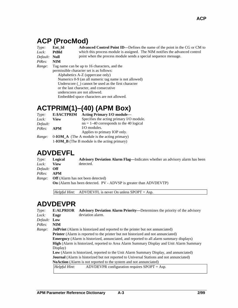
ACP
ACP (ProcMod)Type: Ent_IdLock: PtBldDefault: NullPtRes: NIM
Advanced Control Point ID—Defines the name of the point in the CG or CM towhich this process module is assigned. The NIM notifies the advanced controlpoint when the process module sends a special sequence message.
Range: Tag name can be up to 16 characters, and thepermissible character set is as follows:
Alphabetics A-Z (uppercase only)Numerics 0-9 (an all numeric tag name is not allowed)Underscore (_) cannot be used as the first characteror the last character, and consecutiveunderscores are not allowed.Embedded space characters are not allowed.
ACTPRIM(1)–(40) (APM Box)Type: E:$ACTPRIMLock: ViewDefault:PtRes: APM
Acting Primary I/O module—Specifies the acting primary I/O module.nn = 1–40 corresponds to the 40 logicalI/O modules.Applies to primary IOP only.
Range: 0-IOM_A (The A module is the acting primary)1-IOM_B (The B module is the acting primary)
ADVDEVFLType: LogicalLock: ViewDefault: OffPtRes: APM
Advisory Deviation Alarm Flag—Indicates whether an advisory alarm has beendetected.
Range: Off (Alarm has not been detected)On (Alarm has been detected. PV - ADVSP is greater than ADVDEVTP)
Helpful Hint: ADVDEVFL is never On unless SPOPT = Asp.
ADVDEVPRType: E:ALPRIORLock: EngrDefault: LowPtRes: NIM
Advisory Deviation Alarm Priority— Determines the priority of the advisorydeviation alarm.
Range: JnlPrint (Alarm is historized and reported to the printer but not annunciated)Printer (Alarm is reported to the printer but not historized and not annunciated)Emergncy (Alarm is historized, annunciated, and reported to all alarm summary displays)High (Alarm is historized, reported to Area Alarm Summary Display and Unit Alarm SummaryDisplay)Low (Alarm is historized, reported to the Unit Alarm Summary Display, and annunciated)Journal (Alarm is historized but not reported to Universal Stations and not annunciated)NoAction (Alarm is not reported to the system and not annunciated)Helpful Hint: ADVDEVPR configuration requires SPOPT = Asp.

APM Parameter Reference Dictionary A-4 2/99
ADVDEVTP
ADVDEVTPType: RealLock: SuprDefault: NaNPtRes: APM
Advisory Deviation Alarm Trip Point— An alarm will be generated when thedifference between PV and ADVSP exceeds the value in this parameter.
Range: > 0.0NaN
Helpful Hint: 1. ADVDEVTP change requires SPOPT = Asp .2. Alarm generation requires ASPPROC = Enable and
abs(PV - ADVSP) > ADVDEVTP.When abs(PV - ADVSP) < ADVDEVTP * .9 alarm returns to normal.
ADVSPType: RealLock: SuprDefault: N/APtRes: APM
Advisory Setpoint in Engineering Units
Range: SPLOLM to SPHILM
Helpful Hint: ADVSP change requires (SPOPT = Asp) + (ASPPROC = Enable).Alarm generation requires ASPPROC = Enable andabs(PV - ADVSP) > ADVDEVTP.When abs(PV - ADVSP) < ADVDEVTP * .9 alarm returns to normal.
ADVSPPType: RealLock: ViewDefault: N/APtRes: APM
Advisory Setpoint in Percent
Range: N/A
Helpful Hint: ADVSPP cannot be viewed unless SPOPT = Asp.

APM Parameter Reference Dictionary A-5 2/99
ALENBST
ALENBSTType: E:ALENBSTLock: OperDefault: EnablePtRes: NIM
Alarm Enable Status—Defines the alarm reporting function that is to be usedwhen an alarm condition is detected in this data point. Note that even whenalarms are disabled, the alarm indicators still appear on the Group and Detaildisplays. With Release 510 and later software, the word DIS appears in halfheight text above the tag name on the Point Detail or Group Display for a pointwith ALENBEST set to Disable.
Range: Displayed Logged Reported to EIPEnable Yes Yes YesDisable No Yes YesInhibit No No No
Helpful Hint: ALENBST should not be set to Disable or Inhibit for points critical to safeoperations. For Box Flag points, this parameter applies to only slots 1through 128.
Reference: See Engineer’s Reference Manual, SW09-605, Section 8, Alarm Management,for more information on what should happen under different possible alarmactions.
NOTE
The access lock for the ALENBST parameter is configurable through System-Wide Values.
ALMOPT (DigIn)Type: E:$ALMOPTLock: Eng/PBDefault: NonePtRes: APM
Alarming Option— Defines the alarming option for a digital input point whoseDITYPE is Status.
Range: 0-None (No alarms are to be detected.)1-Offnorml (Off Normal; alarm if current PV state is not the PVNORMAL state. PVNORMALis defined by the STATETXT(0) or STATETXT(1) descriptor, as configured by the user.2-ChngofSt (An alarm is generated when the digital input changes state in either direction. Note that IOP firmware must support Change of State Reporting.)
Helpful Hint: ALMOPT configuration requires DITYPE = Status.

APM Parameter Reference Dictionary A-6 2/99
ALPRIOR
ALPRIOR (ProcMod)Type: E:ALPRIORLock: EngrDefault: LowPtRes: NIM
Alarm Priority— Defines the alarm priority for Process Module points. Notethat even when the alarm priority is Journal, the alarm indicators still appear onthe Group and Detail displays.
Range: Emergncy (Alarm is historized, annunciated, and reported to all alarm summary displays)High (Alarm is historized, reported to Area Alarm Summary Display and Unit Alarm SummaryDisplay)Low (Alarm is historized, reported to the Unit Alarm Summary Display, and annunciated)JnlPrint (Alarm is historized and reported to the printer but not annunciated)Printer (Alarm is reported to the printer but not historized and not annunciated)Journal (Alarm is historized but not reported to Universal Stations and not annunciated)NoAction (Alarm is not reported to the system and not annunciated)
Helpful Hint: Access to ALPRIOR is by schematic or CL. ALPRIOR is retained in R600 forcompatibility with earlier software. Use SEQPR for new points.
Reference: See Engineer’s Reference Manual, SW09-605, Section 8, Alarm Management,for more information on what should happen under different possible alarmactions.
ALPRIOR (DigIn, DigCmp, FL)Type: E:ALPRIORLock: EngrDefault: LowPtRes: NIM
Composite Alarm Priority— When read, returns a value equal to the highestconfigured priority among all alarm parameters for the point. When written, setsall of the point’s alarm priority parameters equal to the value being stored. Notethat individual parameters such as BADPVPR, etc. can be stored individually.If a point’s separate alarm priorities are all set to the same priority, ALPRIOR iscompatible with R400 and earlier software.
Range: Emergncy (Alarm is historized, annunciated, and reported to all alarm summary displays)High (Alarm is historized, reported to Area Alarm Summary Display and Unit Alarm SummaryDisplay)Low (Alarm is historized, reported to the Unit Alarm Summary Display, and annunciated)JnlPrint (Alarm is historized and reported to the printer but not annunciated)Printer (Alarm is reported to the printer but not historized and not annunciated)Journal (Alarm is historized but not reported to Universal Stations and not annunciated)NoAction (Alarm is not reported to the system and not annunciated)
Helpful Hint: Access to ALPRIOR is by schematic or CL. No value is actually read fromALPRIOR on a read and no value is actually stored to ALPRIOR on a write.Values are copied to and from the separate alarm priorities.
Reference: See Engineer’s Reference Manual, SW09-605, Section 8, Alarm Management,for more information on what should happen under different possible alarmactions.
ANAME(1)–(3) (ProcMod)Type: String_8Lock: ViewDefault: SpacesPtRes: APM
Abnormal Sequence Name—Indicates the name of the abnormal handlercurrently being executed by the process module. A value of " " means that anabnormal handler is not executing. ANAME(1) returns the abnormal handlername, while both ANAME(2) and ANAME(3) return the names of the twoabnormal subroutine levels being executed.
Range: N/A
APM Parameter Reference Dictionary A-7 2/99
AOCALIB
AOCALIB(1)–(168)Type: LogicalLock: Eng/PBDefault:PtRes: APM
AO Calibration In Progress Flag—Shows which AO modules are in the processof calibration.
Range: Off (No calibration in progress)On (Calibration in progress)
ARWNET (RegCtl)Type: E:WINDUPLock: ViewDefault: NormalPtRes: APM
Windup Status of the Input—Indicates the windup status for the SP or anotherinitializable input.
Range: 0-Normal (Free to move in either direction)1-Hi (Free to move in the lower direction)2-Lo (Free to move in the higher direction)3-HiLo (Not free to move in any direction)
ARWOP (RegCtl)Type: E:WINDUPLock: ViewDefault: NormalPtRes: APM
Windup Status of the Output—Indicates the output (OP) windup status.
Range: 0-Normal (Free to move in either direction)1-Hi (Free to move in the lower direction)2-Lo (Free to move in the higher direction)3-HiLo (Not free to move in any direction)
ASSOCDSPType: String_8Lock: EngrDefault: BlankPtRes: NIM
Associated Display—Specifies a user configured schematic that is associatedwith this point. Available on Release 510 and later software.
Range: N/A
Helpful Hint: The specified associated display can be called from a Point Detail Display, orfrom any summary display or the Group display when the point is selected.
ASPPROC (RegCtl)Type: E:ASPPROCLock: SuprDefault: DisablePtRes: APM
Advisory SP Processor State
Range: 0-Disable (Disallow advisory deviation alarming)1-Enable (Allow advisory deviation alarming)
Helpful Hint: ASPPROC change requires SPOPT = Asp.

APM Parameter Reference Dictionary A-8 2/99
ASTEP
ASTEP(1)–(3) (ProcMod)Type: String_8Lock: ViewDefault: SpacesPtRes: APM
Abnormal Step Name—ASTEP(1) indicates the step name of the abnormalhandler that is executing in this process module. A value of “ “ means noabnormal handler is presently executing. Both ASTEP(2) and ASTEP(3) indicatethe step names of the first and second level subroutines called from the abnormalhandler.
Range: N/A
ASTMT(1)–(3) (ProcMod)Type: IntegerLock: ViewDefault: BlankPtRes: APM
Abnormal Statement Number—ASTMT(1) indicates the statement number ofthe abnormal handler that is presently executing in the process module. BothASTMT(2) and ASTMT(3) give statement numbers for first and second levelsubroutines executing from an abnormal handler. A value of 0 indicates nosequence is being executed.
Range: 0 to 255
AUTMODFL (RegCtl)Type: LogicalLock: ViewDefault: N/APtRes: APM
Automatic Mode Flag—Indicates whether the current mode of the point isAutomatic.
Range: Off (Current mode is not Automatic)On (Current mode is Automatic)
AUXDATA1 (SI-Array — Generic Modbus)Type: RealLock: EngDefault: NaNPtRes: APM
FTA Driver Auxiliary Data 1— Keep Alive Address for Modbus devices.Specifies the address of a coil that is written to every 10 seconds (Force SingleCoil On function). NaN (dashes) = Keep Alive function is inactive.
Range: 1 - 9999, NaN
Helpful Hint: AUXDATA1 can be configured separately for each Array point. No two Array points should write to the same coil address. This parameter should be set to NAN if it is not being used.
AUXDATA2 (SI-Array — Generic Modbus)Type: RealLock: EngDefault: NaNPtRes: APM
FTA Driver Auxiliary Data 2— Specifies the time interval that the FTA waitsbefore a message retry to the Modbus is attempted. NaN (dashes) indicates a 1.5second timeout.
Range: .25 - 5 Sec., NaN
Helpful Hint: After three retries, a message timeout error is displayed on the Point Detail display. AUXDATA2 can be configured separately for each Array point. This parameter should be set to NAN if it is not being used.

APM Parameter Reference Dictionary A-9 2/99
AUXDATA3
AUXDATA3 (SI-Array — Generic Modbus)Type: RealLock: EngDefault: NaNPtRes: APM
FTA Driver Auxiliary Data 3— Signaling mode.Modem support (ininteger/decimal format). Integer = 232 or 485.(232 = EIA-232, 485 = EIA-485 Multidrop).Decimal (EIA-232 only) = .0 or .1 (.0 = no modem control, .1 = modem control).NaN (dashes) = 232.0 (EIA-232 without modem control).
Range: 232.0, 232.1, or 485.0
Helpful Hint: All array points that are loaded to the same FTA must have the same AUXDATA3 settings. This parameter should be set to NAN if it is not being used.
AUXDATA4 (SI-Array — Generic Modbus)Type: RealLock: EngDefault: NaNPtRes: APM
FTA Driver Auxiliary Data 4— Baud Rate.Parity (in integer/decimal format).Baud Rates = 1200, 2400, 4800, 9600, or 19200.Parity: .0 = no parity, .1 = odd parity, .2 = even parity.NaN (dashes) = 9600.1 = (9600 baud, odd parity).
Range: integer = 1200, 2400, 4800, 9600, or 19200decimal = .0, .1, or .2
Helpful Hint: All array points that are loaded to the same FTA must have the same AUXDATA4 settings. This parameter should be set to NAN if it is not being used.
AV (DigIn)Type: IntegerLock: OperDefault: 0PtRes: APM
Accumulated Value in Engineering Units—Indicates the current valueaccumulated in the accumulator.
Range: 0..32767
AVDELTHS (PI)Type: Integer The Last Half-second’s AVLock: ViewDefault: 0PtRes: APMRange: > 0
AVDEV1FL (Totalizr)Type: LogicalLock: ViewDefault: N/APtRes: APM
Accumulated Value; 1st Deviation Flag—Indicates whether PVCALC isgreater than AVTV minus AVDEV1TP. (PVCALC > AVTV - AVDEV1TP).This is the first "slowdown" or "near-target" flag.
Range: Off (PVCALC is not > AVTV - AVDEV1TP)On (PVCALC is > AVTV - AVDEV1TP)

APM Parameter Reference Dictionary A-10 2/99
AVDEV1TP
AVDEV1TP (Totalizr)Type: RealLock: SuprDefault: NaNPtRes: APM
Accumulated Value; 1st Deviation Trip Point (deviation from AVTV)
Range: > 0.0,NaN
AVDEV2FL (Totalizr)Type: LogicalLock: ViewDefault: N/APtRes: APM
Accumulated Value; 2nd Deviation Flag—Indicates whether PVCALC isgreater than AVTV minus AVDEV2TP. (PVCALC > AVTV - AVDEV2TP).This is the second "slowdown" or "near-target" flag.
Range: Off (PVCALC is not > AVTV - AVDEV2TP)On (PVCALC is > AVTV - AVDEV2TP)
AVDEV2TP (Totalizr)Type: RealLock: SuprDefault: NaNPtRes: APM
Accumulated Value; 2nd Deviation Trip Point (deviation from AVTV)
Range: > 0.0,NaN
AVGTF (NIM, APM Box)Type: RealLock: ViewDefault: 1.00 MinutesPtRes: APM
Average Statistics Single Lag Filter Time Constant—Defines the filter time inthe single lag filter used to calculate average values of the performance statistics.
Range: N/A
AVSTS (PI)Type: E:PVVALSTLock: ViewDefault: BadPtRes: APM
Value Status of AV
Range: 0-Bad2-Normal

APM Parameter Reference Dictionary A-11 2/99
AVTV
AVTV (DigIn)Type: IntegerLock: OperDefault: 0PtRes: APM
Accumulator Target Value—Specifies the target value of the accumulator.AVTV appears on a group or detail display as the SP value.
Range: 0 to 32767
Helpful Hint: AVTV change requires DITYPE = Accum.
AVTV (Totalizr)Type: RealLock: OperDefault: NaNPtRes: APM
Accumulator Target Value—Specifies the target value of the totalizer. AVTVappears on a group or detail display as the SP value.
Range: N/A,NaN
AVTVFLType: LogicalLock: ViewDefault: N/APtRes: APM
Accumulated Value Target Reached Flag—AVTVFL is the accumulatedvalue's "target value reached" flag. It is turned On whenever PVCALC • AVTV.Parameter AVTV contains the target value last entered by the operator.
Range: OffOn

APM Parameter Reference Dictionary A-12 2/99

APM Parameter Reference Dictionary B-1 2/99
B
-B-
B (Automan, MulDiv, RatioCtl, RegCtl Summer)Type: RealLock: OperDefault: 0.0PtRes: APMRange: N/A
Overall Bias—Defines the overall bias which consists of BO plus BI. Refer tothe APM Control Functions and Algorithms manual for a detailed description.
B0 (AutoMan, MulDiv, RatioCtl, RegCtl Summer)Type: RealLock: ViewDefault: 0.0PtRes: APM
Last Operator-Entered Output Bias
B1 (RatioCtl)Type: RealLock: SuprDefault: 0.0PtRes: APM
Output Bias Constant—If the Calcultr PV algorithm is being used inconjunction with this algorithm, the value of B1 should be the same as C3.
Range: N/A
B2 (RatioCtl)Type: RealLock: SuprDefault: 0.0PtRes: APM
Bias for Input X2—If the Calcultr PV algorithm is being used in conjunctionwith this algorithm, the value of B2 should be the same as C4.
Range: N/A
BADCTLFLType: LogicalLock: ViewDefault: OffPtRes: APM
Bad-Control Alarm Flag— Indicates whether a bad control alarm has beendetected.
Range: Off (Bad-control alarm not present)On (Bad-control alarm present)

APM Parameter Reference Dictionary B-2 2/99
BADCTLOP
BADCTLOPType: E:$BADCTLOLock: EngrDefault: No_ShedPtRes: APM
Bad Control Option—Indicates if the mode sheds to manual when bad PV orCV occurs for regulatory control points. It also shows the value of the output.
Range: 0-No_Shed (The point holds its output and mode, resuming control after initialization uponrecovery)
1-ShedHold (The mode sheds to manual, the mode attribute goes to operator, while the output isheld and external mode switching is disabled)
2-ShedLow (The mode sheds to manual, the mode attribute goes to operator, while the outputgoes to -6.9% and external mode switching is disabled)
3-ShedHigh (The mode sheds to manual, the mode attribute goes to operator, while the outputgoes to 106.9% and external mode switching is disabled)
4-ShedSafe (The mode sheds to manual, the mode attribute goes to operator, while the outputgoes to SafeOP and external mode switching is disabled. If SafeOP is NaN, theoutput is held as if the Bad Control Option is ShedHold.
BADCTLPRType: E:ALPRIORLock: EngrDefault: LowPtRes: NIM
Bad Control Alarm Priority— Defines the priority of the bad control alarm.
Range: JnlPrint (Alarm is historized and reported to the printer but not annunciated)Printer (Alarm is reported to the printer but not historized and not annunciated)Emergncy (Alarm is historized, annunciated, and reported to all alarm summary displays)High (Alarm is historized, reported to Area Alarm Summary Display and Unit Alarm SummaryDisplay)Low (Alarm is historized, reported to the Unit Alarm Summary Display, and annunciated)Journal (Alarm is historized but not reported to Universal Stations and not annunciated)NoAction (Alarm is not reported to the system and not annunciated)
BADOCFL (RegCtl)Type: LogicalLock: ViewDefault: OFFPtRes: APM
Bad Output Connection Flag (BADOC) Alarm—ON indicates that the RegCtlpoint cannot drive at least one Analog Output point (out of 4 possible). Thealarm appears on the Alarm Summary display and in the Real Time Journal as aBADOC alarm. If it is the highest level alarm on the point, it appears on thePoint Detail or Group displays as BOC.
Range: Off (Point is not in alarm)On (Point is in alarm)
APM Parameter Reference Dictionary B-3 2/99
BADOC1FL
BADOC1FLType: LogicalLock: ViewDefault: OFFPtRes: APM
Bad Output Connection Flag 1—ON indicates that the RegCtl point cannotdrive Output 1 to an AO point (if configured).
Range: OffOn
BADOC2FLType: LogicalLock: ViewDefault: OFFPtRes: APM
Bad Output Connection Flag 2—ON indicates that the RegCtl point cannotdrive Output 2 to an AO point (if configured).
Range: OffOn
BADOC3FLType: LogicalLock: ViewDefault: OFFPtRes: APM
Bad Output Connection Flag 3—ON indicates that the RegCtl point cannotdrive Output 3 to an AO point (if configured).
Range: OffOn
BADOC4FLType: LogicalLock: ViewDefault: OFFPtRes: APM
Bad Output Connection Flag 4—ON indicates that the RegCtl point cannotdrive Output 4 to an AO point (if configured).
Range: OffOn
APM Parameter Reference Dictionary B-4 2/99
BADOCPR
BADOCPR (RegCtl)Type: E:ALPRIORLock: EngrDefault: LowPtRes: NIM
Bad Output Connection (BADOC) Alarm Priority— Indicates the priority ofthe Bad Output Connection (BADOC) alarm
Range: NoActionJnlPrintPrinterJournalLowHighEmergncy
Helpful Hint: The value of this parameter can be changed on the Point Detail display withEngineering keylevel access.
BADOCOPT (RegCtl)Type: LogicalLock: Eng/PbDefault: OFFPtRes: APM
Bad Output Connection Alarm Option (BADOC)—ON indicates that the BadOutput Connection (BADOC) alarm can be generated (or is permitted).
Range: Off (BADOC alarms are suppressed)On (BADOC alarms are permitted)
Helpful Hint: The value of this parameter can be changed on the Point Detail display withEngineering keylevel access.
BADPVFLType: LogicalLock: ViewDefault: OffPtRes: APM
Bad PV Flag—Indicates that a bad PV value has been detected at this data point.For an analog input, a bad PV is defined as a PV whose value is NaN (Not aNumber).
Range: Off (PV is not bad)On (PV is bad)
BADPVFL (Array)Type: LogicalLock: View
Default: On whenEXTDATA = IO_FL,IO_NN, IO_STR
Off whenEXTDATA = NonePtRes: APM
Serial Interface Database Status Flag—This parameter can be set by either anArray point, a Serial Interface IOP, or a Serial Interface FTA-driver programwhen the data in the array is not being updated. An example would be loss ofcommunications between the SI FTA and the field device. When theEXTDATA parameter = None, BADPVFL is always Off.
Range: Off (Data is not bad)On (Data is bad)

APM Parameter Reference Dictionary B-5 2/99
BADPVFL
BADPVFL (DI)Type: LogicalLock: ViewDefault: OnPtRes: APM
Bad PV Flag—Indicates that a bad PV value has been detected at this data point.BADPVFL is shown on the detailed display only when PNTFORM = Full.
For a Digital Input, the Bad PV Flag is on when:
• The PV source is not equal to Manual and DITYPE is set to Accumulator.
• The PV source has just been switched to Substituted but the PV has not yet been updated.
• The PV source = Substitute or Auto and PTEXECST = Inactive or themodule is not in the RUN state.
• PVSOURCE = Auto and there is no FTA connected or there is a Soft Failthat is preventing this chanel from working.
Range: Off (PV is not bad)On (PV is bad)
BADPVFL (DevCtl, DigComp)Type: LogicalLock: ViewDefault: OffPtRes: APM
Bad PV Flag—For a Digital Composite or Device Control point, the Bad PVFlag is is set to ON when the PV is bad.
Range: Off (PV is not bad)On (PV is bad)
BADPVPRType: E:ALPRIORLock: EngrDefault: LowPtRes: NIM
Bad PV Alarm Priority— Defines the priority of the bad PV alarm.
Range: Emergncy (Alarm is historized, annunciated, and reported to all alarm summary displays)High (Alarm is historized, reported to Area Alarm Summary Display and Unit Alarm SummaryDisplay)Low (Alarm is historized, reported to the Unit Alarm Summary Display, and annunciated)JnlPrint (Alarm is historized and reported to the printer but not annunciated)Printer (Alarm is reported to the printer but not historized and not annunciated)Journal (Alarm is historized but not reported to Universal Stations and not annunciated)NoAction (Alarm is not reported to the system and not annunciated)

APM Parameter Reference Dictionary B-6 2/99
BADPVTXT
BADPVTXT (DevCtl, DigComp, NIM)Type: String_8Lock: PtBldDefault: BADPtRes: NIM
Bad PV State Descriptor—Defines the state descriptor that is displayed whenthe digital composite or device control point state is indeterminate or bad. Thebad state can result when the PV input signals from the process are in aninconsistent state (e.g., for a valve, the limit switches indicating open and closedare on at the same time). This state descriptor is configured on a per point basisand is valid only when the PVTXTOPT parameter is On.
Range: The permissible character set for the up to eight character descriptor is as follows:Alphabetics A-Z (upper case only)Numerics 0-9,Underscore (_)
BADSVFL (DevCtl)Type: LogicalLock: ViewDefault: OffPtRes: APM
Bad SV Alarm Flag—Indicates a bad secondary value alarm.
Range: Off (Good data being read)On (SV parameter = BAD or NaN)
BADSVPR (DevCtl)Type: E:ALPRIORLock: EngrDefault: LowPtRes: NIM
Bad SV Alarm Priority— Indicates the alarm priority for the secondary value.
Range: JnlPrint (Alarm is historized and reported to the printer but not annunciated)Printer (Alarm is reported to the printer but not historized and not annunciated)Emergncy (Alarm is historized, annunciated, and reported to all alarm summary displays)High (Alarm is historized, reported to Area Alarm Summary Display and Unit Alarm SummaryDisplay)Low (Alarm is historized, reported to the Unit Alarm Summary Display, and annunciated)Journal (Alarm is historized but not reported to Universal Stations and not annunciated)NoAction (Alarm is not reported to the system and not annunciated)
BFF (PidFf)Type: RealLock: SuprDefault: 0.0PtRes: APM
Feed Forward Input Bias—Defines the bias value for multiplicative action.
Range: N/A
BHALMFL1–BHALMFL7Type: String_2Lock: ViewDefault:PtRes: NIM
Alarm Flags
Range: Hexadecimal characters 00 - FF

APM Parameter Reference Dictionary B-7 2/99
BIAS
BIAS (Pid)Type: RealLock: OperDefault: 0.0PtRes: APM
Bias—Defines the value which is added to the SP.
Range: BSLOLM to BSHILM
BNDRESET (NIM, APM Box)Type: LogicalLock: OperDefault: OffPtRes: APM
Bounds (Minimum/Maximum) Statistics Reset Flag—A write of ON resetsthe following maximum/minimum statistics to their default values: APM CPUfree percentage events, UCN transaction, UCN parameter statistics and UCNaverage statistics.
Range: Off /On
Helpful Hint: A read of BNDRESET always returns OFF.
BNDRSTIM (NIM, APM Box)Type: TimeLock: ViewDefault: Time of APMStartupPtRes: APM
Time of Last Bounds (Minimum/Maximum) Statistics Reset.
Range: N/A
Helpful Hint: This statistic can be viewed on the Toolkit Displays.
BOXCLR(0)–(2) (DevCtl, DigComp)Type: E:BOXCOLORLock: Eng/PB
Default: Green [Upper-box default (State 1)]
Yellow[Middle-box default(State 0)]
Red [Lower-box default (State 2)]PtRes: NIM
Box Color for Digital Displays—Defines the color of the upper, middle, andlower boxes that are used to display the current state of the point on theGroup and Detail Displays. The lower box and its default (Red) do not applyif NOSTATES = 2 for this point.
Range: RedGreenWhiteBlackCyanYellowBlueMagenta
Helpful Hint: BOXCLR has an access lock of View if PNTFORM = Component.
APM Parameter Reference Dictionary B-8 2/99
BOXCLR(0)–(1)
BOXCLR(0)–(1) (DigIn, Flag)Type: E:BOXCOLORLock: Eng/PB
Default: Green [Upperbox default color (State1)]
Yellow [Lower-box default color(State 0)]PtRes: NIM
Box Color for Digital Displays—Defines the color of the upper and lowerboxes that are used to display the current state of the point on the Group andDetail Displays. Boxes are applicable when DITYPE is Latched or Status.
Range: RedGreenWhiteBlackCyanYellowBlueMagenta
BSHILMType: RealLock: SuprDefault: 50.0PtRes: APM
Bias High Limit— Defines the upper limit of the bias.
Range: > BSLOLM,NaN
Helpful Hint: Entering NaN disables the BSHILM function with NaN being stored in thedatabase.
BSLOLMType: RealLock: SuprDefault: -50.0PtRes: APM
Bias Low Limit— Defines the lower limit of the bias.
Range: < BSHILM,NaN
Helpful Hint: Entering NaN disables the BSLOLM function with NaN being stored in thedatabase.

APM Parameter Reference Dictionary B-9 2/99
BYPASS
BYPASS (DevCtl, DigComp)Type: LogicalLock: OperDefault: OffPtRes: APM
Interlock Bypass—Allows bypassing the permissive and override interlockswhen ON. The Safety Override Interlock (SI0) is not affected. Only applies ifOverride Option (OROPT) is selected.
Range: Off (Interlocks not bypassed)On (Interlocks bypassed)
BYPASS (ORSel)Type: LogicalLock: OperDefault: OffPtRes: APM
Override Input Bypass Enable—Allows the operator to select the bypassfunction for the X1-X4 inputs.
Range: Off (Bypass of inputs is not allowed)On (Bypass of inputs is allowed)
BYPASSX1–BYPASSX4 (ORSel)Type: LogicalLock: Oper
Default: BYPASSX1 = OffBYPASSX2–X4 = On
PtRes: APM
Bypass X1–X4 Input—Refer to the APM Control Functions andAlgorithms manual for a detailed description. BYPASSXn being Ondoes not bypassX1–X4 unless BYPASS = On.
Range: OffOn

APM Parameter Reference Dictionary B-10 2/99

APM Parameter Reference Dictionary C-1 2/99
C
-C-
C (FlowComp, Summer, Totalizer, and VdtLdLg)Type: RealLock: SuprDefault: 1.0PtRes: APM
Scale Factor—Value in C is used in the calculation of PVCALC. Refer to theAPM Control Functions and Algorithms manual for the equation.
Range: Anything except NaN
C1–C2 (FlowComp)Type: RealLock: SuprDefault: 1.0PtRes: APM
Correction Constants—Values in C1 and C2 are used in the calculation ofPVCALC, and serve as factors in compensating for assumed design conditions.Refer to the APM Control Functions and Algorithms manual for a detaileddescription.
Range: C1 > 0.1C2 > 0.1
C1–C2 (PI)Type: RealLock: SuprDefault: 1.0PtRes: APM
Scaling Constants—Values in C1 and C2 are used in the calculation ofPVCALC. Refer to the APM Control Functions and Algorithms manual for adetailed description.
Range: C1 > 0C2 > 0
C1–C2 (VdtLdLg)Type: RealLock: SuprDefault: 1.0PtRes: APM
Scaling Constant For Input P1–P2—Values in C1 and C2 are used in thecalculation of TD (fixed time delay) and TDNEW (calculated new delay time).
Range: > 0.0
C1–C4 (Calcultr)Type: RealLock: SuprDefault: N/APtRes: APM
Intermediate Results of Calculations
Range: N/A
APM Parameter Reference Dictionary C-2 2/99
C1–C6
C1–C6 (Summer)Type: RealLock: SuprDefault: 1.0PtRes: APM
Scaling Constants 1-6—Defines the scaling constants to be used with therespective inputs P1-P6.
Range: N/A
C1–C4DESC (Logic)Type: String_8Lock: EngrDefault: BlankPtRes: APM
Custom Alarm Descriptors—Defines the state for each of the four customalarms.
Range: 8 Character String
C1–C4FL (Logic)Type: LogicalLock: ProgramDefault: OffPtRes: APM
Custom Alarm Flags—Defines the state for each of the four custom alarms.These flags can be written to if C1–C4SRC=None.
Range: Off (A custom alarm is not active)On (A custom alarm is active)
C1–C4PR (Logic)Type: E:ALPRIORLock: EngrDefault: LowPtRes: NIM
Custom Alarm Priorities—Defines the alarm priorities for each of the fourcustom alarms.
Range: JnlPrint (Alarm is historized and reported to the printer but not annunciated)Printer (Alarm is reported to the printer but not historized and not annunciated)Emergncy (Alarm is historized, annunciated, and reported to all alarm summary displays)High (Alarm is historized, reported to Area Alarm Summary Display and Unit Alarm Summary Display)Low (Alarm is historized, reported to the Unit Alarm Summary Display, and annunciated)Journal (Alarm is historized but not reported to Universal Stations and not annunciated)NoAction (Alarm is not reported to the system and not annunciated)
C1–C4SRC (Logic)Type: E:$LGALSRCLock: PtBldDefault: NonePtRes: APM
Custom Alarm Source—Indicates the alarm source for each of the four customalarms.
Range: NONE (No source configured for alarms)L1..L12 (Alarm source is the configured input connection; they can be either On or Off)SO1..SO24 (Alarm source is the status output (SOn) from another logic block)FL1..FL12 (Alarm source is a local flag; they can be either On or Off)

APM Parameter Reference Dictionary C-3 2/99
CABLESTS
CABLESTS (NIM)Type: IntegerLock: ViewDefault: N/APtRes: NIM
Overall Cable Status for a UCN Node
Range: 0-(Both cables are OK)1-(Cable A has failed)2-(Cable B has failed)3-(Both cables have failed)
CALCEXP (Calcultr)Type: String_40Lock: Eng/PBDefault: blankPtRes: APM
Calculator Expression—Allows the user to set up an equation that can be up to40 characters in length, which is to be solved by the Calcultr algorithm. Inputvalues P1-P6 and intermediate results values C1-C4 can be used in the equation.
Range: N/A
CALIBALL (1)–(168)Type: LogicalLock: Eng/PBDefault: OffPtRes: APM
Full Calibration Enable Flag
Range: Off (Card calibration is disabled)On (Card calibration is enabled)
CALIBRJ (1)–(168)Type: LogicalLock: Eng/PBDefault: OffPtRes: APM
Reference Junction Calibration Enable Flag
Range: Off (Disable Reference Junction calibration)On (Enable Reference Junction calibration)

APM Parameter Reference Dictionary C-4 2/99
CASREQ
CASREQ (AnalgOut, RegCtl)Type: E:CASREQLock: ProgDefault: NotReqPtRes: APM
Remote Cascade Request Flag—Defines whether the remote cascade mode hasbeen requested for the data point. The remote cascade mode exists whenMODE is changed to Cas and RCASOPT is Ddc or DdcRsp. When a request tochange MODE to Cas is received from a US or a program, MODE does notimmediately change to Cas. Instead, CASREQ is set to Request and a -Cappears to the right of the mode indicator on the Group and Detail displays.When continuous control in an AM determines that CASREQ contains Request,it requests the mode to go to Cas, and changes CASREQ to NotReq.
Should the point shed while it is in the remote cascade mode, MODE goes to thestate defined in SHEDMODE, and CASREQ goes back to Request.
Range: 0-NotReq (Remote cascade mode request not made)1-Request (Remote cascade mode request made; operator or program has requested the
cascade mode)
Helpful Hint: CASREQ does not apply for an AnalgOut point if RCASOPT = None.CASREQ does not apply for a RegCtl point unless RCASOPT = Spc, Ddc,or DdcRsp.If Spc has been entered for the RCASOPT parameter, the AM writes to the setpoint.Ddc is the only remote cascade option for an analog output point.
CHPINHWY (UCN)Type: E:CHPINDACLock: SuprDefault: EnablePtRes: NIM
Automatic Checkpoint Inhibit
Range: 0-Enable (Enable automatic checkpointing of data bases on this UCN)1-Inhibit (Inhibit automatic checkpointing)
CHPINOPR (APM Box)Type: E:CHPINDACLock: SuprDefault: EnablePtRes: NIM
Automatic Checkpoint Inhibit Operation— Defines whether automaticdatabase saves are to be performed for the devices connected to this NIM.
Range: Enable (Automatic database saves are enabled)Inhibit (Automatic database saves are inhibited)
APM Parameter Reference Dictionary C-5 2/99
CIDSTN(1)–CIDSTN(4)
CIDSTN(1)–CIDSTN(4) (RegCtl)Type: Prm_IDLock: PtBldDefault: Based on
CTLALGID,CTLEQN, N
PtRes: APM
Control Input Connection Destination—Defines the parameter name (PV, SP,etc.) in the RegCtl point that is to receive the value fetched using the"Tagname.Parameter" or the hardware reference address specified in parameterCISRC, Control Input Connection Source.
Range: N/A
Helpful Hint: 1. CIDSTN must contain a legitimate parameter of one to eight characters.2. Default to PV, SP, or some other parameter depends on parameters
CTLALGID, CTLEQN, and M.
CISRC(1)–CISRC(4) (RegCtl)Type: Ent.PrmLock: PtBldDefault: null.nullPtRes: APM
Control Input Connection Source—Defines the "Tagname.Parameter" of theparameter whose value is to be obtained and then stored in one of up to fourRegCtl algorithm inputs. Refer to the APM Control Functions and Algorithmsmanual for a detailed description.
Range: Use Tagname.Parameter for tagged points where Tagname can be up to 16 characters, and thepermissible character set is as follows:
Alphabetics A-Z (uppercase only)Numerics 0-9 (an all numeric tag name is not allowed)Underscore (_) cannot be used as the first character or the last character, and consecutiveunderscores are not allowed.Embedded space characters are not allowed.An * is used to default to this point’s tag name.Parameter name can be up to eight characters and must be a legitimate parameter name.
CJTACT (STI)
Type: LogicalLock: Eng/PtBldDefault: OnPtRes: APM
Internal Cold Junction Temperature—Defines whether the smart temperaturetransmitter’s internal cold-junction reference is to be used, or an externally-provided cold-junction reference is to be used.
Range: On (Transmitter’s internal cold-junction temperature is active)Off (External cold-junction temperature is active)
CLPZMXC (UCN)Type: LogicalLock: ViewDefault: N/APtRes NIM
Overall Cable Status for UCN Cable A
Range: Off (Cable A status is OK)On (Cable A status is not OK)

APM Parameter Reference Dictionary C-6 2/99
CLPZMXP
CLPZMXP (UCN)Type: LogicalLock: ViewDefault: N/APtRes NIM
Overall Cable Status for UCN Cable B
Range: Off (Cable B status is OK)On (Cable B status is not OK)
CMDDISFL (DevCtl, DigComp)Type: LogicalLock: ViewDefault: OffPtRes: APM
Command Disagree Alarm Flag—Indicates whether a field device did not goto the commanded state within the allowed feedback time.
Range: Off (No command disagree alarm)On (Command disagree alarm has been detected by this point)
Helpful Hint: A slow-responding field device can cause a premature alarm. If so, adjust thetime in parameter FBTIME.
CMDDISPR (DevCtl, DigComp)Type: E:ALPRIORLock: EngrDefault: LowPtRes: NIM
Command Disagree Alarm Priority—Defines the alarm priority of commanddisagree, command fail, and uncommanded change alarms.
Range Emergncy (Alarm is historized, annunciated, and reported to all alarm summary displays)High (Alarm is historized, reported to Area Alarm Summary Display and Unit Alarm SummaryDisplay)Low (Alarm is historized, reported to the Unit Alarm Summary Display, and annunciated)JnlPrint (Alarm is historized and reported to the printer but not annunciated)Printer (Alarm is reported to the printer but not historized and not annunciated)Journal (Alarm is historized but not reported to Universal Stations and not annunciated)NoAction (Alarm is not reported to the system and not annunciated)
CMDFALFL (DevCtl, DigComp)Type: LogicalLock: ViewDefault: OffPtRes: APM
Command Fail Alarm Flag—Indicates if the PV failed to move after the outputcommand within the allowed command fail time. Command Fail Alarm priorityis determined by CMDDISPR.
Range: Off (PV moved after the output command)On (PV did not move after the output command)
APM Parameter Reference Dictionary C-7 2/99
CMDFALTM
CMDFALTM (DevCtl, DigComp)Type: IntegerLock: Supr if
CMDFALTMis changed froma non-zero valueto a zero value,else Eng/PB
Default: 0PtRes: APM
Command Fail Timeout—Sets the amount of time (in seconds)that the point should wait before generating a “command fail”alarm, if the PV has not changed after changing the output.Command Fail Alarm priority is determined by CMDDISPR.
Range: 0 to 999 seconds (0 indicates command fail alarming is disabled)
CMDHWREVType: String_2Lock: ViewDefault:PtRes: APM
APMM Communications Daughter Card Revision
Range: Hexadecimal characters 00 - FF
CNTLLOCKType: E:ACCLVLLock: EngrDefault: OPERATORPtRes: APM
Control Lock— Attempts to write values in the following parameters aresubject to the access-lock value contained in CNTLLOCK. The check isbypassed for the exceptions.
Parameter ExceptionsPROCMOD New value = STARTSEQEXEC NoneSEQMODE NoneOVERPHAS SEQEXEC = FAIL or ERROROVERSTEP SEQEXEC = FAIL or ERROROVERSTAT SEQEXEC = FAIL or ERROR
Range: 0-OPERATOR - Operator and higher keylock positions allow store access.1-SUPERVIS - Supervisor and higher keylock positions allow store access.2-ENGINEER - Engineer and higher keylock positions allow store access.3-PROGRAM - Only the program has store access.

APM Parameter Reference Dictionary C-8 2/99
CODSTN
CODSTN(1)–CODSTN(4) (RegCtl)Type: Universal
Ent.PrmLock: PtBldDefault: null.nullPtRes: APM
Control Output Connection Destination—Defines up to four different"Tagname.Parameter" or hardware reference address destinations to which theoutput value from RegCtl point is to be written. Refer to the APM ControlFunctions and Algorithms manual for a detailed description.
Range: Use Tagname.Parameter for tagged points where Tagname can be up to 16 characters, and thepermissible character set is as follows:
Alphabetics A-Z (uppercase only)Numerics 0-9 (an all numeric tag name is not allowed)Underscore (_) cannot be used as the first character or the last character, and consecutiveunderscores are not allowed.Embedded space characters are not allowed.An * is used to default to this point’s tag name.Parameter name can be up to eight characters and must be a legitimate parameter name.
Use the hardware reference address !MTmmSss.Parameter for untagged or tagged points whereMT is the IOP type, such as AO (analog output)mm is the IOP Card number (1-40)ss is the slot number on the IOP Card (refer to SLOTNUM parameter)Parameter name can be up to eight characters and must be a legitimate parameter name.
COMCFAVG (APM Box)Type: RealLock: ViewDefault: NaNPtRes: APM
Average APM Communication CPU Free Percentage—The averagepercent of time the Communications Processor is not busy.
Range: 0 - 100
Helpful Hint: This statistic can be viewed on the Toolkit Displays.
COMCFMAX (APM Box)Type: RealLock: ViewDefault: NaNPtRes: APM
Maximum APM Communication CPU Free Percentage—The maximumpercent of time the Communications Processor is not busy.
Range: 0 - 100
Helpful Hint: This statistic can be viewed on the Toolkit Displays.
COMCFMIN (APM Box)Type: RealLock: ViewDefault: NaNPtRes: APM
Minimum APM Communication CPU Free Percentage—The minimumpercent of time the Communications Processor is not busy.
Range: 0 - 100
Helpful Hint: This statistic can be viewed on the Toolkit Displays.

APM Parameter Reference Dictionary C-9 2/99
COMDAUGH
COMDAUGHType: LogicalLock: ViewDefault:PtRes: APM
APMM Communications Daughter Card Present Flag.
Range: Off (No daughter card present)On (Daughter card present)
COMDAYType: IntegerLock: ViewDefault: N/APtRes: APM
Creation Day of APMM Communications Personality.
Range: 1 - 31
COMFWREVType: String_2Lock: ViewDefault:PtRes: APM
APMM Communications Firmware Revision.
Range: Hexadecimal characters 00 - FF
COMHWREVType: String_2Lock: ViewDefault:PtRes: APM
APMM Communications Hardware Revision.
Range: Hexadecimal characters 00 - FF
COMMAND (DigIn)Type: E:COMMANDLock: OperDefault: NonePtRes: APM
Accumulator Commands—Allow the operator to control the accumulator.
Range: 0-None (No effect on accumulator)1-Start (Start the accumulator)2-Stop (Stop the accumulator)3-Reset (Reset the accumulation to zero)
Helpful Hint: COMMAND applies only when DITYPE = Accum.

APM Parameter Reference Dictionary C-10 2/99
COMMAND
COMMAND (STI)
Type: E:COMMANDLock: OperDefault: NonePtRes: APM
Command—Allows the user to do database transfers between the STI point andthe smart transmitter, and to calibrate the transmitter.
NOTE
During an up-load operation, previously unseen data is read from the transmitter databaseand stored in the STI database. If this data is not desired, the data can be restored by usingthe checkpoint restore or load IDF functions.
Range: 0-None (A command has not been issued by the STI point)1-DnLoadDb (Loads the transmitter parameters from the STI point data base into thetransmitter)2-UpLoadDb (Loads the transmitter data base from the transmitter into the STI point)3-Set_LRV (Sets the Lower Range Value)4-Set_URV (Sets the Upper Range Value)5-Cor_LRV (Corrects the Lower Range Value)6-Cor_URV (Corrects the Upper Range Value)7-Cor_Inpt (Corrects the zero point for the PV value)8-RstCor (Sets all input calibration parameters to their default values)
Helpful Hint: If PV or PV_SV has been entered for the DECONF parameter, the only command supported is DnLoadDB.
COMMAND (Timer)Type: E:COMMANDLock: OperDefault: NonePtRes: APM
Timer Commands—Allow the operator to control the operation of the timerdata point.
Range: 0-None (No effect on the timer)1-Start (Starts the timer)2-Stop (Stops the timer)3-Reset (Resets the timer to zero)4-RestStrt (Resets the timer, then starts the timer)
COMMAND (Totalizr)Type: E:COMMANDLock: OperDefault: NonePtRes: APM
Totalizer Commands—Allow the operator to control the operation of thetotalizer.
Range: 0-None (No effect on totalizer)1-Start (Starts the totalizer)2-Stop (Stops the totalizer)3-Reset (Resets the totalizer to RESETVAL)

APM Parameter Reference Dictionary C-11 2/99
COMMONTH
COMMONTHType: IntegerLock: ViewDefault: N/APtRes: APM
Creation Month of APMM Communications Personality
Range: 1 - 12
COMNAMEType: String_8Lock: ViewDefault:PtRes: APM
APMM Communications Personality Name
Range:
COMPHILM (FlowComp)Type: RealLock: SuprDefault: 1.25PtRes: APM
Compensation Term High Limit—Defines the upper limit of the COMPTERM(compensation term) parameter.
Range: COMPLOLM to 10.0,NaN
Helpful Hint: Entering NaN disables high-limit checking by forcing its value to the extreme(10.0).
COMPLOLM (FlowComp)Type: RealLock: SuprDefault: 0.8PtRes: APM
Compensation Term Low Limit—Defines the lower limit of the COMPTERM(compensation term) parameter.
Range: 0.0 to COMPHILM,NaN
Helpful Hint: Entering NaN disables low-limit checking by forcing its value to the extreme(0.0).
COMPTERM (FlowComp)Type: RealLock: ViewDefault: 1.0PtRes: APM
Compensation Term—This term differs in each of the five flow compensationequations, A through E. Refer to the APM Control Functions and Algorithmsmanual for a detailed description.
Range: COMPLOLM to COMPHILM

APM Parameter Reference Dictionary C-12 2/99
COMREV
COMREVType: IntegerLock: ViewDefault:PtRes: APM
APMM Communications Software Revision
Range:
COMVERSType: IntegerLock: ViewDefault:PtRes: APM
APMM Communications Software Version
Range:
COMYEARType: IntegerLock: ViewDefault: N/APtRes: APM
Creation Year of APMM Communications Personality
Range: 0 - 99
CONTCUTType: LogicalLock: ProgDefault: OffPtRes: APM
Contact Cut Out —Defines whether alarms detected at this data point are to becut out to prevent this data point’s alarms from being reported to the operator.The alarms continue to be reported to the AM or CM through the EIPPCODEparameter.
CONTCUT can be used to cutout alarms on a point when the alarms aregenerated because of specific conditions at other points which themselves havealarms. As an example, the user could configure a logic point so that the logicpoint would monitor the nuisance alarm conditions and then store the contactcutout state of this point using an output connection. It can also be stored by thesequence program in the APM or the AM which could monitor the processconditions to determine when the alarms have to be suppressed.
Range: Off (Alarms are not cut out)On (Alarms are cut out)
Helpful Hint: Cutout alarms behave the same as inhibited alarms; that is, when a point’scontact cutout state is true—
• alarms are not distributed to the US or HM• return to normal events are not distributed to the US or HM• EIP events triggered by the alarm condetion are not distributed
For APM Box Flag points, CUTOUT applies to only slots 1–128.
APM Parameter Reference Dictionary C-13 2/99
COUNTDWN
COUNTDWN (DigIn)Type: LogicalLock: Eng/PBDefault: OffPtRes: APM
Accumulator Count Down Flag—Determines whether the accumulator is tocount down or count up.
Range: Off (Accumulator is to count up)On (Accumulator is to count down)
Helpful Hint: COUNTDWN configuration requires DITYPE = Accum.
CPMSGSEC (NIM)Type: RealLock: ViewDefault: 0PtRes: NIM
Number of Checkpoint Messages—Specifies the Number of CheckpointMessages per second.
Range: N/A
CPTIMAVG (NIM)Type: RealLock: ViewDefault: 0PtRes: NIM
Averaage Time to Complete a Checkpoint Request—Specifies the AverageTime (in msec.) to Complete a Checkpoint Request.
Range: N/A
APM Parameter Reference Dictionary C-14 2/99
CPTIMMAX
CPTIMMAX (NIM)Type: RealLock: ViewDefault: 0PtRes: NIM
Maximum Time to Complete a Checkpoint Request—Specifies the MaximumTime (in msec.) to Complete a Checkpoint Request.
Range: N/A
CRIOLORN (1)–(4) (APM Box)Type: IntegerLock: ViewDefault: 0PtRes: APM
Current Hour IOL Fetch/Store Overrun Counter— A counter thataccumulates and shows the number of I/O Link fetch/store time outs that haveoccurred during the current hour. In arrays 1 through 4, the counter is indexedby the cycle. In array 0, the counter is totaled for all cycles.
Range: > 0
CRPPXORN (0)–(8) (APM Box)Type: IntegerLock: ViewDefault: 0PtRes: APM
Current Hour Point Processing Overrun Counter—A counter thataccumulates and shows the number of APMM point processing overruns thathave occurred during the current hour. In arrays 1 through 8, the counter isindexed by the cycle. In array 0, the counter is totaled for all cycles.
Range: > 0
CRUCNORN (APM Box)Type: IntegerLock: ViewDefault: 0PtRes: APM
Current-Hour UCN Access Overruns—Indicates the number of UCN accessoverruns that have occurred in the current hour. Refer to the APM ControlFunctions and Algorithms manual for a detailed description of overrun handling.
Range: > 0
CTLACTNType: E:POLARITYLock: Eng/PBDefault: ReversePtRes: APM
Control Action— Defines the direct/reverse action of this algorithm’s output.
Range: 0-Direct (As PV increases, output increases)1-Reverse (As PV increases, output decreases)

APM Parameter Reference Dictionary C-15 2/99
CTLALGID
CTLALGID (RegCtl)Type: E:$PMMCTAL
Lock: PtBldDefault: NullPtRes: APM
Control Algorithm Identifier— Defines the algorithm that is to be usedfor this RegCtl point.
Range: 0-Null (No algorithm selected)1-Pid (Proportional, Integral, Derivative)2-PidFf (PID with Feedforward)3-PidErfb (PID with External Reset Feedback)7-RatioCtl (Ratio Control)8-RampSoak (Ramp Soak)9-AutoMan (Auto Manual Station)10-IncrSum (Incremental Summer)11-Switch (Switch)12-ORSel (Override Selector)13-PosProp (Position Proportional)14-PIDPosProp (PID with Position Proportional output)
CTLCFAVG (APM Box)Type: RealLock: ViewDefault: NaNPtRes: APM
Average APM Control Processor CPU Free Percentage—The averagepercent of time the APM Control Processor is not busy.
Range: 0 - 100
Helpful Hint: This statistic can be viewed on the Toolkit Displays
CTLCFMAX (APM Box)Type: RealLock: ViewDefault: NaNPtRes: APM
Maximum APM Control Processor CPU Free Percentage—The maximumpercent of time the APM Control Processor is not busy.
Range: 0 - 100
Helpful Hint: This statistic can be viewed on the Toolkit Displays.
CTLCFMIN (APM Box)Type: RealLock: ViewDefault: NaNPtRes: APM
Minimum APM Control Processor CPU Free Percentage—The minimumpercent of time the APM Control Processor is not busy.
Range: 0 - 100
Helpful Hint: This statistic can be viewed on the Toolkit Displays.
APM Parameter Reference Dictionary C-16 2/99
CTLDAY
CTLDAYType: IntegerLock: ViewDefault: N/APtRes: APM
Creation Day of APMM Control Personality
Range: 1 - 31
CTLEQN (AutoMan)Type: E:ALGOEQNLock: Eng/PBDefault: EqAPtRes: APM
Control Equation Type
Range: 0-EqA (CV = X1 + B +BI)1-EqB (CV = X1 + (K*X2) + BI)
CTLEQN (ORSel)Type: E:ALGOEQNLock: PtBldDefault: EqAPtRes: APM
Control Equation Type—Defines whether the highest or the lowest input isto be selected.
Range: 0-EqA (Selects the highest input)1-EqB (Selects the lowest input)
CTLEQN (Pid)Type: E:ALGOEQNLock: PtBldDefault: EqAPtRes: APM
Control Equation Type—Defines how Proportional (P) or gain, Integral (I)or reset, and Derivative (D) action is applied to a PID-type algorithm’scalculated Error (PV - SP).
Range: 0-EqA (P, I, and D act on Error)1-EqB (P and I act on Error, D acts on PV)2-EqC (I acts on Error, P and D act on PV)3-EqD (Integral-only control)
CTLEQN (Switch)Type: E:ALGOEQNLock: Eng/PBDefault: EqAPtRes: APM
Control Equation Type—Defines whether the operator, the user-writtenprogram, or the logic slot controls the selection of one of the four inputs(X1-X4) as the input to this algorithm.
Range: 0-EqA (Operator controls switch position)1-EqB (Program or logic point controls switch position)

APM Parameter Reference Dictionary C-17 2/99
CTLFWREV
CTLFWREVType: String_2Lock: ViewDefault: N/APtRes: APM
APMM Control Firmware Revision
Range: Hexadecimal characters 00 - FF
CTLHWREVType: String_2Lock: ViewDefault: N/APtRes: APM
APMM Control Hardware Revision
Range: Hexadecimal characters 00 - FF
CTLMONTHType: IntegerLock: ViewDefault: N/APtRes: APM
Creation Month of APMM Control Personality
Range: 1 - 12
CTLNAMEType: String_8Lock: ViewDefault: N/APtRes: APM
APMM Control Personality Name
Range:
CTLOPT (APM Box)Type: LogicalLock: PtBldDefault: OnPtRes: APM
APMM Control Processor Option
Range: On (All point types can be configured)Off (DigComp, Logic, RegCtl, or RegPV points cannot be configured; only I/O points can be
configured. This usually means that the control processor hardware is missing from theAPM).

APM Parameter Reference Dictionary C-18 2/99
CTLREDUN
CTLREDUNType: LogicalLock: ViewDefault:PtRes: APM
APMM Control Redundancy Present Flag
Range: OffOn
CTLREVType: IntegerLock: ViewDefault:PtRes: APM
APMM Control Personality Revision
Range:
CTLVERSType: IntegerLock: ViewDefault:PtRes: APM
APMM Control Personality Version
Range:
CTLYEARType: IntegerLock: ViewDefault: N/APtRes: APM
Creation Year of APMM Control Personality
Range: 0 - 99
CTRLINIT (RegCtl)Type: LogicalLock: ProgDefault: OffPtRes: APM
Control Initialization Request Flag—A user-written program or a logic slotcan cause a data point to initialize by setting the point’s control initialization-request flag to On.
Range: OffOn

APM Parameter Reference Dictionary C-19 2/99
CURCOMFL
CURCOMFLType: E:$PMMHFSTLock: ViewDefault:PtRes: APM
Current APMM Communications Board Failure
Range: Null (Unknown Error)Pwrdwn (Power Down )Lr_Par (Parity Error)Lr_Lram (Local Ram Error)Lr_Ck (Local Ram Check)Lr_Exc (Local Ram Exception)Lr_Hrev (Local Ram Hardware Revision)Mm_Hrev (Memory Board Hardware Revision)Lr_Tmr (Local Ram Timer Error)Lr_Ptrn (Local Ram Pattern Check Error)Lr_Byte (Local Ram Byte Error)Lr_Adcd (Local Ram Address Decode Test)Lr_Addl (Local Ram Additional Check)Lr_Clrr (Local Ram Scrub Incomplete)Sr_Par (Shared Ram Parity)Sr_Ptrn (Shared Ram Pattern Check Error)Sr_Adcd (Shared Ram Address Decode Test)Sr_Addl (Shared Ram Additional Checks)Gr_Par (Global Ram Parity)Gr_Ptrn (Global Ram Pattern Check Error)Gr_Byte (Global Ram Byte Error)Gr_Adcd (Global Ram Address Decode Test)Gr_Addl (Global Ram Additional Checks)Gr_Clrr (Global Ram Scrub Incomplete)31_Nr (IOL Processor, No Response or Failure)31_Aliv (IOL Processor, Transmitter Not Alive)31_Iltn (IOL Processor, Illegal Transition)Nmi_Unk (Unknown NMI Request)Baducnn (UCN Address Parity or Duplicate Address)Nr (No Response From Other Processor)Mrft (Memory Reference Table (Pattern Build Fail)Nomtos (No MTOS Readout)Llc_Comm (LLC Communication Fatal Error)Ucndrv (UCN Driver, Fatal Error)Rd_Hrev (Redundancy Card Version/Revision Mismatch)Sw_Error (Software Error)Md_Hrev (Modem Card Version/Revision Mismatch)Da_Ptrn (Daughter Card Pattern Test)Da_Byte (Daughter Card Byte Write Test)Da_Adcd (Daughter Card Address Decode)Da_Addl (Daughter Card Additional Test)Da_Clrr (Daughter Card Scrub Incomplete)Rd_Snps (Redundancy Card 96 Kw Snapshot Error)Rd_Bslk (Redundancy Card Bus Lock Fail)
APM Parameter Reference Dictionary C-20 2/99
CURCTLFL
CURCTLFLType: E:$PMMHFSTLock: ViewDefault:PtRes: APM
Current APMM Control Failure
Range: Null (Unknown Error)Pwrdwn (Power Down )Lr_Par (Parity Error)Lr_Lram (Local Ram Error)Lr_Ck (Local Ram Check)Lr_Exc (Local Ram Exception )Lr_Hrev (Local Ram Hardware Revision)Mm_Hrev (Memory Board Hardware Revision)Lr_Tmr (Local Ram Timer Error)Lr_Ptrn (Local Ram Pattern Check Error)Lr_Byte (Local Ram Byte Error)Lr_Adcd (Local Ram Address Decode Test)Lr_Addl (Local Ram Additional Checks)Lr_Clrr (Local Ram Scrub Incomplete)Sr_Par (Shared Ram Parity)Sr_Ptrn (Shared Ram Pattern Check Error)Sr_Adcd (Shared Ram Address Decode Test)Sr_Addl (Shared Ram Additional Checks)Gr_Par (Global Ram Parity)Gr_Ptrn (Global Ram Pattern Check Error)Gr_Byte (Global Ram Byte Error)Gr_Adcd (Global Ram Address Decode Test)Gr_Addl (Global Ram Additional Checks)Gr_Clrr (Global Ram Scrub Incomplete)31_Nr (IOL Processor, No Response or Failure)31_Aliv (IOL Processor, Transmitter Not Alive)31_Ilatn (IOL Processor, Illegal Transition)Nmi_Unk (Unknown NMI Request)Baducnn (UCN Address Parity or Duplicate Address)Nr (No Response From Other Processor)Mrft (Memory Reference Table - Pattern Build Fail)Nomtos (No MTOS Readout)Llc_Comm (LLC Communication Fatal Error)Ucndrv (UCN Driver, Fatal Error)Rd_Hrev (Redundancy Card Version/Revision Mismatch)Sw_Error (Software Error)Md_Hrev (Modem Card Version/Revision Mismatch)Da_Ptrn (Daughter Card Pattern Test )Da_Byte (Daughter Card Byte Write Test )Da_Adcd (Daughter Card Address Decode)Da_Addl (Daughter Card Additional Tests)Da_Clrr (Daughter Card Scrub Incomplete)Rd_Snps (Redundancy Card 96 Kw Snapshot Error)Rd_Bslk (Redundancy Card Bus Lock Fail)

APM Parameter Reference Dictionary C-21 2/99
CURIOLFL
CURIOLFLType: E:$IOMHFLock: ViewDefault:PtRes: APM
Current APMM IOL Interface Failure
Range: Unknown - (Unknown Error)Powerdwn - (Power Is Off)Invprgex (Invalid Program Execution)Epromerr (EPROM Error)Ramcnter (Ram Contents Error)Ramadrer (Ram Address Error)Dpaerror (Device Physical Address Error)Dsaerror (Device Soft Address Error)Rxbufofl (Receive Buffer Overflow Error)Ioljaber (IOL Jabber Error; Module saw or talked too much on link)Badpgjmp (Bad Program Jump)Adcincmp (A/D Incompatible)Adoutovf (A/D Overflow)Adoutudf (A/D Underflow)Adccaler (A/D Calibration Error)Baddcltc (Bad DC LTC)Dmt_tmot (Deadman Time Out)Mltoutfl (Multiple Output Failure)Datbusfl (Data Bus Failure)Baddarng (Bad A/D Range)Mstrtmot (Master Timeout)Ctrcktfl (Counter Circuit Failure)
CURPINAM (n)Type: String_8Lock: ViewDefault: N/APtRes: IOP
Current PI Filename—Defines the personality Image filename thatcurrently resides in this IOP whenre n is the IOP number 1 - 40.
Range: N/A
CURSEGID (RampSoak)Type: E:CURSEGIDLock: OperDefault: Ramp1PtRes: APM
Current Segment ID—Defines the current ramp or soak segment.
Range: 0-Ramp1 1-Soak12-Ramp2 3-Soak2
: and :20-Ramp1121-Soak1122-Ramp1223-Soak12

APM Parameter Reference Dictionary C-22 2/99
CUTOFFLM
CUTOFFLM (Totalizr)Type: RealLock: SuprDefault: 0.0PtRes: APM
Zero-Flow Cutoff Limit— Allows the user to specify a cutoff limit such thatwhen the value of input parameter P1 falls below the limit specified, its value isreplaced by 0.0.
Range: > 0.0,NaN (Cutoff limit is not applicable)
CUTOFFLM (VdtLdLag)Type: RealLock: SuprDefault: NaNPtRes: APM
Zero-Flow/Belt-Speed Cutoff Limit—Allows the user to specify a cutoff limitfor equations C and D.
Range: > 0.0,NaN (Bypasses the limit check)
CVType: RealLock: ProgDefault: NaNPtRes: APM
Calculated Variable—The result (calculated value) of the calculation of thecontrol algorithm. The value can be in percent or in engineering units dependingon the control algorithm.
Range: N/A
CVEUHIType: RealLock: EngrDefault: 100.0
(GPM,PPH, etc.)
PtRes: APM
Calculated Value's High Limit in Engineering Units
Range: > CVEULO
Helpful Hint: CV ranges track X-input ranges if CTLALGID = AutoMan, ORSel, IncrSum,or Switch. For CTLALGID = PidErfb and RampSoak, CV ranges are configurable. For CTLALGID = Pid, Pidff, and RatioCtl, if NOCOPTS = 0, then the CV ranges are configurable, otherwise, the CV ranges track the ranges of the secondary output connection.
CVEULOType: RealLock: EngrDefault: 0.0 (GPM,
PPH, etc.)PtRes: APM
Calculated Value's Low Limit in Engineering Units
Range: < CVEUHI
Helpful Hint: Same as above for CVEUHI.

APM Parameter Reference Dictionary C-23 2/99
CYCLEOPT
CYCLEOPT (RampSoak)Type: E:$CYCLOPTLock: OperDefault: CyclicPtRes: APM
Ramp/Soak Cycle Option—Defines whether the ramp/soak cycle stopsafter a single cycle, or is continuous. For detailed information, refer to theAPM Control Functions and Algorithms manual.
Range: 0-Single (Stop after completing one complete cycle)1-Cyclic (Repeat complete cycles over and over)
Helpful Hint: If Cyclic is entered, repeats complete ramp/soak cycles after Mode is changed from Man to Auto. If Single is entered, performs one ramp/soak cycle and then stops.
CYCLETIM (PosProp, PIDPosPr)Type: RealLock: SuprDefault: 10.0 secondsPtRes: APM
PosProp Output Cycle Time in Seconds—Determines the rate at which raiseor lower output pulses are going to be generated. PV - SP determines the widthof the output pulse.
Range: 0.25 to 1000.0 seconds

APM Parameter Reference Dictionary C-24 2/99

APM Parameter Reference Dictionary D-1 2/99
D
-D-
D (Summer, VdtLdLag)Type: RealLock: SuprDefault: 0.0PtRes: APM
Overall Bias—Defines the overall bias used in calculating PVCALC.
Range: N/A
D1 (VdtLdLag)Type: RealLock: SuprDefault: 0.0 minutesPtRes: APM
Fixed Deadtime in Minutes—Bias value for the variable time delay.
Range: 0.0 to 400.0 minutes
D1, D2 (DigComp, DevCtl)Type: LogicalLock: ViewDefault: OffPtRes: APM
Digital Input 1 Status and Digital Input 2 Status—Separately indicateswhether input 1 and input 2 are on or off.
Range: Off (No input present)On (Input is present)
D1_0 (DigComp, DevCtl)Type: E:$PVSTATSLock: ViewDefault: PVState0PtRes: APM
Digital Input 1 Equal to A PV State of 0—Defines the PV state thatcorresponds to input D1 = Off. D1_0 = true only if INPTDIR = Direct and thefield contact feeding D1 is open, or INPTDIR = Reverse and contact iscleared.
Range: 0-PVState0 (STATETXT(0) describes D1 = 0)1-PVState1 (STATETXT(1) describes D1 = 0)
Helpful Hint: Applies only if NODINPTS = 1. D1_0 is always the opposite state of D1_1.
D1_1 (DigComp, DevCtl)Type: E:$PVSTATSLock: Eng/PBDefault: PVState1PtRes: APM
Digital Input 1 Equals A PV State of 1—D1_1 defines the PV state thatcorresponds to D1 (Input 1 status) = On. D1_1 = true only if INPTDIR =Direct and the field contact feeding D1 is closed, or INPDIR = Reverse andcontact is open.
Range: 0-PVState0 (STATETXT(0) describes D1 = 1)1-PVState1 (STATETXT(1) describes D1 = 1)
Helpful Hint: D1_1, Digital Input 1 Equal To A PV State Of 1, applies only if NODINPTS =1. D1_1 is always the opposite state of D1_0 and vice versa.
APM Parameter Reference Dictionary D-2 2/99
D2
D2 (VdtLdLag)Type: RealLock: SuprDefault: 0.0PtRes: APM
Bias for Input P2
Range: > 0.0
D2D1_00 (DigComp, DevCtl)Type: E:$PVSTATSLock: Eng/PBDefault: MovPVPtRes: APM
D2_D1 Zero_Zero PV State—Defines the PV state descriptor that is to beused and displayed when inputs D2 and D1 are both Off (00).
Range: 0-PVState0 (STATETXT(0) descriptor)1-PVState1 (STATETXT(1) descriptor)2-BadPV (BADPVTXT descriptor)3-MovPV (MOVPVTXT descriptor)4-PVState2 (STATETXT(2) descriptor)
Helpful Hint: D2D1_00 configuration requires NODINPTS = 2. Option PVState2 cannot be selected unless NOSTATES = 3. STATETXT(0–2) is configured for each DigComp or DevCtl point; BADPVTXT and MOVPVTXT are configured during Box Data Point configuration for all DigComp or DevCtl points in this box.
D2D1_01 (DigComp, DevCtl)Type: E:$PVSTATSLock: Eng/PBDefault: PVState1PtRes: APM
D2D1 Zero_One PV State—Defines the PV state descriptor that is to be usedand displayed when input D2 is Off and input D1 is On (01).
Range: 0-PVState0 (STATETXT(0) descriptor)1-PVState1 (STATETXT(1) descriptor)2-BadPV (BADPVTXT descriptor)3-MovPV (MOVPVTXT descriptor)4-PVState2 (STATETXT(2) descriptor)
Helpful Hint: D2D1_01 configuration requires NODINPTS = 2. Option PVState2 cannot bespecified unless NOSTATES =3. STATETXT(0–2) is configured for eachDigComp or DevCtl tag name; BADPVTXT and MOVPVTXT are configured during Box Data Point configuration for all DigComp or DevCtl points in the box.

APM Parameter Reference Dictionary D-3 2/99
D2D1_10
D2D1_10 (DigComp, DevCtl)Type: E:$PVSTATSLock: Eng/PBDefault: PVState0PtRes: APM
D2D1 One_Zero PV State—Defines the PV state descriptor that is to be usedand displayed when input D2 is On and input D1 is Off (10).
Range: 0-PVState0 (STATETXT(0) descriptor)1-PVState1 (STATETXT(1) descriptor)2-BadPV (BADPVTXT descriptor)3-MovPV (MOVPVTXT descriptor)4-PVState2 (STATETXT(2) descriptor)
Helpful Hint: D2D1_10 configuration requires NODINPTS = 2. Option PVState2 cannot bespecified unless NOSTATES = 3. STATETXT(0–2) is configured for eachDigComp or DevCtl point; BADPVTXT and MOVPVTXT are configured during Box Data Point configuration for all DigComp or DevCtl points in the box.
D2D1_11 (DigComp, DevCtl)Type: E:$PVSTATSLock: Eng/PBDefault: BadPVPtRes: APM
D2D1 One_One PV State—Defines the PV state descriptor that is to be usedand displayed when inputs D2 and D1 are both On (11).
Range: 0-PVState0 (STATETXT(0) descriptor)1-PVState1 (STATETXT(1) descriptor)2-BadPV (BADPVTXT descriptor)3-MovPV (MOVPVTXT descriptor)4-PVState2 (STATETXT(2) descriptor)
Helpful Hint: D2D1_11 configuration requires NODINPTS = 2. Option PVState2 cannot bespecified unless NOSTATES = 3. STATETXT(0–2) is configured for eachDigComp or DevCtl point; BADPVTXT and MOVPVTXT are configuredduring Box Data Point configuration for all DigComp or DevCtl points in thebox.

APM Parameter Reference Dictionary D-4 2/99
DAMPING
DAMPING (STI)
Type: RealLock: Supr/ViewDefault: 0.0PtRes: APM
Damping—Defines the first-order PV filtering option for the smart transmitter.User can also implement PV filtering by using this parameter or the TFparameter; however, DAMPING is the preferred parameter. If DAMPING hasbeen configured at the transmitter using the Universal Station, the STI IOPadjusts the entered value to one of the values in the range shown below for theappropriate transmitter type. For Multivariable transmitters with SENSRTYP =SFM the IOP will not adjust the damping value.
Any real number in the range of damping specified by the transmitter usermanual can be used. It can be changed only when the STI point execution statePTEXECST is Inactive.
Range: Transmitter TypeSpt Stt Sfm
0.0 0.0 0.00.16 0.30 0.50.32 0.70 1.00.48 1.5 2.01.00 3.10 3.02.0 6.3 4.04.0 12.7 5.08.00 25.5 10.016.0 51.1 50.032.0 102.3 100NaN NaN NaN
DATE (APM Box)Type: TimeLock: ViewDefault: N/APtRes: APM
Current Date/Time—Value of the LCN date in the APM.
Range: N/A
DAY (APM Box)Type: IntegerLock: ViewDefault: N/APtRes: APM
Current Day—Value of the LCN date in the APM.
Range: 1 to 31
DB_VALID(1)–(40) (APM Box)Type: E:$DBVALIDLock: EngrDefault: InvalidPtRes: APM
Database Valid—Indicates if the database is valid. The IOP cannot be set toRUN unless the database is valid.
Range: Valid (Database is valid)Invalid (Database is not valid)
APM Parameter Reference Dictionary D-5 2/99
DEADBAND
DEADBAND(1)–(24) (Logic)Type: RealLock: SuprDefault: 1.0PtRes: APM
Deadband Value—Defines the value of the deadband for the specified logicblock within the logic slot.
Range: > 0.0
Helpful Hint: DEADBAND requires LOGALGID = EQ, NE, GT, GE, LT, or LE.
DEADBANDType: RealLock: SuprDefault: 5.0 %PtRes: APM
Deadband in Percent of Full Scale—Defines the error deadband.
Range: 0.0 to 100.0 %
DEADTIMEType: RealLock: SuprDefault: 0.0PtRes: APM
Deadtime (in seconds)—Additional pulse time required to overcome the frictionin the motor when it begins to move or change direction. It is added to thecalculated pulse time except when the pulse that was issued in the last cycle timewas in the same direction (as the pulse this time), and the pulse width was equalto CYCLETIM.
Range: 0.0 to 60.0 seconds
DEBOUNCE (DigIn)Type: IntegerLock: Engr/PBDefault: 10
millisecondsPtRes: APM
Contact Debounce Time in Milliseconds—The length of time an input mustremain in a new state for it to be declared as a valid event by the DISOE IOP.Refer to the Absolute Delay Across parameter located in the Digital InputProcessor table of the APM Specification and Technical Data.
Range: 0 to 50 milliseconds
DECONF (STI)Type: E:$DECONFLock: Eng/ViewDefault: Pv_Sv_DbPtRes: APM
Digitally Enhanced Configuration Mode—Defines the contents of the data thatwill be sent by the smart transmitter to the STI point.The use of Pv_Db and Pv_Sv_Db is recommended because they offer databasemismatch detection and on-process mismatch recovery.
This parameter can be changed only when the STI point execution statePTEXECST is Inactive.
Range: 0-Analog (Not Supported)1-Pv (Transmits only the PV; 4-byte format)2-Pv_Sv (Transmits the PV and the secondary variable (SV); 4-byte format)3-PV_Db (Transmits the PV and the transmitter database; 6-byte format)4-Pv_Sv_Db (Transmits the PV, SV, and the transmitter database; 6-byte format)Helpful Hint: For the PV_Db and Pv_Sv_Db selections, one byte of the transmitter database
is transmitted each time the PV is transmitted to the STI IOP.
APM Parameter Reference Dictionary D-6 2/99
DELCV
DELCV (IncrSum)Type: RealLock: ViewDefault: N/APtRes: APM
Delta CV in Engineering Units—Indicates the calculated change in the CVoutput value in engineering units.
Range: N/A
DELCV (Pid)Type: RealLock: ViewDefault: N/APtRes: APM
Delta CV in Percent—Indicates the calculated change in the CV output value inpercent.
Range: N/A
DEV (RegCtl)Type: RealLock: ViewDefault: N/APtRes: APM
Deviation—Indicates the deviation (PV - SP) in engineering units.
Range: N/A
DEVADDR (Array)Type: RealLock: PtBldDefault: NaNPtRes: APM
Serial Link Device Address—Indicates the serial link address of the devicecontaining data.
Range: N/A
DEVHIFL (RegCtl)Type: LogicalLock: ViewDefault: OffPtRes: APM
Deviation High Alarm Flag—Indicates whether the DEVHITP has beenexceeded.
Range: Off (No DEVHI alarm)On (DEVHITP has been exceeded)
APM Parameter Reference Dictionary D-7 2/99
DEVHIPR
DEVHIPR (RegCtl)Type: E:ALPRIORLock: EngrDefault: LowPtRes: NIM
Deviation High Alarm Priority— Defines the priority of the deviation highalarm.
Range: JnlPrint (Alarm is historized and reported to the printer but not annunciated)Printer (Alarm is reported to the printer but not historized and not annunciated)Emergncy (Alarm is historized, annunciated, and reported to all alarm summary displays)High (Alarm is historized, reported to Area Alarm Summary Display and Unit Alarm SummaryDisplay)Low (Alarm is historized, reported to the Unit Alarm Summary Display, and annunciated)Journal (Alarm is historized but not reported to Universal Stations and not annunciated)NoAction (Alarm is not reported to the system and not annunciated)
DEVHITP (RegCtl)Type: RealLock: SuprDefault: NaNPtRes: APM
Deviation High Alarm Trip Point— Defines the upper limit for the deviation.
Range: > 0.0,NaN
Helpful Hint: Alarm occurs when the PV is higher than SP + DEVHITP.
DEVLOFL (RegCtl)Type: LogicalLock: ViewDefault: OffPtRes: APM
Deviation Low Alarm Flag—Indicates whether the DEVLOTP has beenexceeded.
Range: Off (DEVLOTP has not been exceeded)On (DEVLOTP has been exceeded)
DEVLOPR (RegCtl)Type: E:ALPRIORLock: EngrDefault: LowPtRes: NIM
Deviation Low Alarm Priority— Defines the priority of the deviation lowalarm.
Range: JnlPrint (Alarm is historized and reported to the printer but not annunciated)Printer (Alarm is reported to the printer but not historized and not annunciated)Emergncy (Alarm is historized, annunciated, and reported to all alarm summary displays)High (Alarm is historized, reported to Area Alarm Summary Display and Unit Alarm SummaryDisplay)Low (Alarm is historized, reported to the Unit Alarm Summary Display, and annunciated)Journal (Alarm is historized but not reported to Universal Stations and not annunciated)NoAction (Alarm is not reported to the system and not annunciated)
APM Parameter Reference Dictionary D-8 2/99
DEVLOTP
DEVLOTP (RegCtl)Type: RealLock: SuprDefault: NaNPtRes: APM
Deviation Low Alarm Trip Point— Defines the lower limit for the deviation.
Range: > 0.0,NaN
Helpful Hint: Alarm occurs when the PV is lower than SP - DEVLOTP.
DHTIMMAX(1) - (5) (NIM)Type: RealLock: ViewDefault: 0PtRes: NIM
Maximum Time to Complete a Data Handler Request—Specifies themaximum time to complete a Data Handler request in msec.
Range: N/A
DISP_SIM (APM Box)Type: LogicalLock: ProgDefault: N/APtRes: APMM
Simulation Indicator Display Switch—see also SIM_TXT
Range: Off (Simulation indicator is not required to be displayedOn (Simulation indicator is required to be displayed
APM Parameter Reference Dictionary D-9 2/99
DISRC(1)–(2)
DISRC(1)–(2) (DigComp, DevCtl)Type: Universal
Ent.PrmLock: PtBldDefault: null.nullPtRes: APM
Digital Composite and Device Control Input-Connection Source—Specifythe sources whose values are to be fetched and delivered to Digital Compositedata point inputs D1 and D2. The source can be specified using the"Tagname.Parameter" format or the hardware reference address format. Refer tothe APM Control Functions and Algorithms manual for a detailed description.
Range: Use Tagname.Parameter format for tagged points where Tagname can be up to 16 characters andthe permissible character set is as follows:
Alphabetics A-Z (uppercase only)Numerics 0-9 (an all numeric tag name is not allowed)Underscore (_) cannot be used as the first character or the last character, and consecutiveunderscores are not allowed.Embedded space characters are not allowed.An * is used to default to this point’s tag name.Parameter name can be up to eight characters, and must be a legitimate parameter name.
Some possible input-connection sources area."DigIn slot Tagname.PVFL"b."DigOut slot Tagname.SO"c."Logic slot Tagname.SO(nn)" where nn = 1–24d."Logic slot Tagname.Fl(nn)" where nn = 1–12e."ProcMod slot Tagname.Fl(nnn)" where nnn = 1–127f."Box Flag slot Tagname.PVFLg."!Box.FL(nnnn)" for a box flag that resides in the same box;
nnnn = 1–16,384h."$NMhhBxx.FL(nnnn)" for a box flag that resides in a different APM box on the same
UCN; hh is the NIM UCN address, xx is the APM box number, andnnnn = 1–4095
Use the hardware reference address !MTmmSss.Parameter for untagged or tagged points whereMT is the IOP type, such as DI (Digital Input)mm is the IOP Card number (1–40)The letter "S" is a constantss is the slot number on the IOP Card (refer to SLOTNUM parameter)Parameter name can be up-to-eight characters and must be a legitimate parameter name.
DITYPEType: E:$DITYPELock: PtBldDefault: StatusPtRes: APM
Digital Input Type— Defines the type of digital input point.
Range: 0-Status (Point is to be used for alarming and event reporting)1-Latched (Point is to be used for event reporting)2-Accum (Point is to be used for accumulating pulses)

APM Parameter Reference Dictionary D-10 2/99
DLYTIME
DLYTIME (DigIn)Type: IntegerLock: SuprDefault: 5 secondsPtRes: APM
Delay Time—For an off-normal alarm, defines the time (in seconds) that a pointwith a previously detected alarm condition is guaranteed to remain in alarm,even if the condition clears. If an alarm condition exists when the delay timerexpires, the point is held in alarm.
For a change of state (COS) alarm, if the PV is in the same state when the delaytimer expires, future state changes are immediately alarmed. If the PV is in theopposite state, a second COS alarm is produced and the delay timer is restarted.
Range: 0 to 60 seconds
DLYTIME(1)–(24) (Logic)Type: RealLock: SuprDefault: 1 secondPtRes: APM
Alarm Delay in Seconds for Logic Block
Range: 1–8000 seconds
Helpful Hint: DLYTIME requires LOGALGID = Pulse, MinPulse, MaxPulse,OnDelay, OffDelay, or Watchdog.
APM Parameter Reference Dictionary D-11 2/99
DODSTN
DODSTN(1)–(3) (DigComp, DevCtl)Type: Universal
Ent.PrmLock: PtBldDefault: null.nullPtRes: APM
Digital Composite and Device Control Output-Connection Destination—Specifies up to three output connection destinations that are to receive the OPoutput from this point. The destination can be specified using the"Tagname.Parameter" format or the hardware reference address format. Refer tothe APM Control Functions and Algorithms manual for a detailed description.
Range: Use Tagname.Parameter for tagged points where Tagname can be up to 16 characters and thepermissible character set is as follows:
Alphabetics A-Z (uppercase only)Numerics 0-9 (an all numeric tag name is not allowed)Underscore (_) cannot be used as the first character or the last character, and consecutiveunderscores are not allowed.Embedded space characters are not allowed.An * is used to default to this point’s tag name.Parameter name can be up to eight characters, and must be a legitimate parameter name.
Some possible output-connection destinations area."DigOut slot tagname.ONPULSE or OFFPULSE"b."DigOut slot Tagname.SO"c."Logic slot Tagname.Fl(nn)" where nn = 7–12d."ProcMod Tagname.Fl(nnn)" where nnn = 1–127e."Flag slot Tagname.PVFLf."!Box.FL(nnnn)" for a box flag that resides in the same APM box; nnnn = 1–16,384.g."$NMhhBxx.FL(nnnn)" for a box flag that resides in a different APM box on the same
UCN; hh is the NIM UCN address, xx is the APM box number, andnnnn = 1–4095.
Use the hardware reference address !MTmmSss.Parameter for untagged or tagged points whereMT is the IOP type, such as DO (Digital Output)mm is the IOP Card number (1–40)The letter "S" is a constant.ss is the slot number on the IOP Card (refer to SLOTNUM parameter)Parameter name can be up to eight characters and must be a legitimate parameter name.
DOTYPE (DigOut)Type: E:$DOTYPELock: PtBldDefault: StatusPtRes: APM
Digital Output Type—Determines the type of digital output point.
Range: 0-Status (Status output type)1-Pwm (Pulse Width Modulated output type)
DSAType: IntegerLock: ViewDefault: N/APtRes: APM
Device Soft Address—The logical address of an IOP: 1-40 for primaryIOPs and 129 - 168 for secondary IOPs.
Range: 1 - 40 for primary IOPs129 - 168 for secondary IOPs

APM Parameter Reference Dictionary D-12 2/99
APM Parameter Reference Dictionary E-1 2/99
EIPPCODE
-E-
EIPPCODEType: Ent_IdLock: EngrDefault: NullPtRes: NIM
Event-Initiated Processing Point Identifier—Defines the tag name of the pointin the AM or CM that is to be notified when an event is detected by this point.
Range: Tag name of the data point can be up to 16 characters and the permissible character set is asfollows:Alphabetics A-Z (uppercase only)Numerics 0-9 (an all numeric tag name is not allowed)Underscore (_) cannot be used as the first character or the last character, and consecutiveunderscores are not allowed.Embedded space characters are not allowed.
Helpful Hint: EIPPCODE configuration requires PNTTYPE = DigIn, DigComp, Logic, Flag or DevCtl and EVTOPT = Eip or Eip_Soe. For APM Box Flag points, this parameter applies only to slots 1 through 128.

APM Parameter Reference Dictionary E-2 2/99
ERRCODE
ERRCODE (Array)Type: String_8Lock: ViewDefault: SpacesPtRes: APM
Serial Interface/Serial Link Communication Error Code—When theBADPVFL parameter = ON, this parameter provides additional information ifinitialized by the serial interface FTA driver program.
SI Array Point Error Code Values
APM
APM Idle— When the APMM status is IDLE, Array point configuration may ormay not be loaded to the SI IOP.Iop Comm—When the APMM status is RUN, Array point configuration is NOTloaded to the SI IOP.
SI IOP
No_FTA—Appears when the power adapter panel is not connected to the IOP.FTA_Comm—Appears when the corresponding FTA is not connected to thepower adapter panel, or when communication between the IOP and FTA hasfailed.CFG_Load—Appears when configuration data is downloaded to the FTA.Mod_Idle—Appears when configuration data is downloaded to the FTA and theIOP is in IDLE mode, or when the IOP operating state is switched from RUN toIDLE.
SI IOP FTA Common
Dev Addr—The device address has a configuration errorData Type—The data type has a configuration errorStartidx—The start index has a configuration error# Elemnt—A number of elements configuration error has occurredConfig—An application-specific configuration error has occurredInv Resp—An invalid field device response has occurredParity, Checksum, MsgTmout, ChrTmout—A field device communicationerror has occurredEx or xx—An exception or other field device error has occurred. The “xx” errorcode is specific to the field deviceFac Test—A factory test is in progressOK—No errors exist
Range: N/A
APM Parameter Reference Dictionary E-3 2/99
ESWAUTO
ESWAUTO (RegCtl)Type: LogicalLock: ProgDefault: OffPtRes: APM
External Switching Flag for Automatic Mode—When On, means that thispoint’s operating mode has been switched from some mode other than automaticto the automatic mode by an external source.
Range: OffOn
ESWCAS (RegCtl)Type: LogicalLock: ProgDefault: OffPtRes: APM
Eternal Switching Flag for Cascade Mode—When On, means that this point’soperating mode has been switched from some mode other than cascade tocascade mode, by an external source.
Range: OffOn
ESWENBST (RegCtl)Type: E:ENBLSTATLock: OperDefault: DisablePtRes: APM
External Mode Switching Enable State—Defines whether external modeswitching is permitted for this point.
Range: 0-Disable (Does not allow external switching of point’s mode)1-Enable (Allows external switching of point’s mode)
Helpful Hint: ESWENBST cannot be changed if parameter SHUTDOWN is On or ifparameter REDTAG is On.
ESWMAN (RegCtl)Type: LogicalLock: ProgDefault: OffPtRes: APM
External Switching Flag for Manual Mode—When On, means that this point’soperating mode has been switched from some mode other than the manual modeto the manual mode by an external source.
Range: OffOn

APM Parameter Reference Dictionary E-4 2/99
EUDESC
EUDESCType: String_8Lock: PtBldDefault: BlankPtRes: NIM
Engineering Units Descriptor—An eight-character descriptor that defines thename of the engineering units (EU) that are displayed on the Group and DetailDisplays for this point as shown in Figure N-1 (see NAME). In this figure,LBS/SEC is the engineering unit descriptor.
Range: Permissible character set consists of all characters on the Engineer’ s Keyboard. Basically this setconsists of alphabetics A-Z, numerics 0-9, and the following special characters: space ! % & ’( ) * + - / : ; > < = ? _ , . $
EUNDESC (1)–(168)Type: String_72Lock: ViewDefault: Blanks
IOP Generic Descriptor—Used as additional display text to help the operatordiagnose potential problems with the IOP. It is primarily used with diagnosticdisplays.
PtRes: APMRange: nn = 1-40 specifies one of the 40 acting primaries.
nn = 129-168 specifies one of the 40 acting secondaries.
EVRCINPGType: LogicalLock: ViewDefault:PtRes: APM
NIM Event Recovery in Progress Flag
Range: OffOn
EVTOPT (DigComp)Type: E:$EVTOPTLock: PtBldDefault: NonePtRes: APM
Event Reporting Option—If EVTOPT = Eip and the PV changes or a PValarm is generated, the AM or CM data point named EIPPCODE is notified anda "process special" on that data point takes place.
Range: 0-None (Event-Initiated Processing is not allowed)1-Eip (Process special is triggered in AM/CM)
Helpful Hint: EVTOPT configuration requires NODINPTS > 0.
APM Parameter Reference Dictionary E-5 2/99
EVTOPT
EVTOPT (DevCtl, DigIn)Type: E:$EVTOPTLock: PtBldDefault: NonePtRes: APM
Event Reporting Option—If EVTOPT = Eip and the PV changes, the AM orCM data point named EIPPCODE is notified and a "process special" on thatdata takes place. If EVTOPT = Soe and a PV change occurs, Sequence OfEvents Processing is notified. If EVTOPT = EipSoe, the actions in both apply.
Range: 0-None (Neither Eip nor Soe is allowed)1-Eip (Process special is triggered in AM/CM)2-Eip_Soe (Eip and Soe are both allowed)3-Soe (Point notifies Sequence of Events Processing)
Helpful Hint: EVTOPT configuration requires DITYPE = Status or Latched. If DITYPE =Latched, EVTOPT cannot = EIPSOE or SOE.
EXTDATA (Array)Type:E:$EXTDATALock: PtBldDefault: NonePtRes: APM
External Data Option—Indicates if either the Array point flags, numerics, orstrings are mapped from a serial interface.
Range: None (None of the flags, numerics, or strings are mapped from a serial interface)IO_FL (IO flags are mapped from a serial interface)IO_NN (IO numerics are mapped from a serial interface)IO_STR (IO strings are mapped from a serial interface)UCN_FL (Reserved for future use)UCN_NN (Reserved for future use)UCN_STR (Reserved for future use)
Helpful Hint: You can map either flags, numerics, or strings from the SerialInterface to a single Array point.
EXTSWOPTType: E:EXTSWOPTLock: Eng/PBDefault: NonePtRes: APM
External Mode Switching Option—External mode switching is typicallyused to establish mode interlocks, or under certain process conditions, torestrict the use of a mode that invokes a higher level of control. Refer to theAPM Control Functions and Algorithms manual for a detailed description ofexternal mode switching.
Range: 0-None (No external mode switching is allowed)1-Ems (External source can change point’s mode)2-Emp (Not implemented)

APM Parameter Reference Dictionary E-6 2/99

APM Parameter Reference Dictionary F-1 2/99
F
-F-
F (FlowComp)Type: RealLock: ViewDefault: NaNPtRes: APM
Flow Input— Indicates the value of the uncompensated flow input. This input isa square-rooted, differential pressure input.
Range: N/A
FAILCODEType: E:IOMHFLock: ViewDefault: N/APtRes: IOP
I/O Processor Hard Fail Status—
Range: 0-Unknown (Unknown status)1-PowerDwn(This IOP Powered Down)2-InvPrgEx (Invalid Program Execution)3-EpromErr (EPROM Checksum Error)4-RamCntEr (RAM Contents Error)5-RamAdrEr (RAM Addressing Error)6-DpaError (Device Physical Address Error)7-DsaError (Device Soft Address Error)8-RxBufOfl (I/O Link Receive Buffer Overflow)9-IOLJaber (I/O Link Jaber Circuit Failure)10- 11-BadPgJmp(Illegal Value of Case Control)12-AdCIncmp (A to D Conversion Incomplete)13-AdOutOvf (A to D Output Value Overflow)14-AdOutUdf (A to D Output is less than Zero)15-AdCCalEr (A to D Calibration is incorrect)16-BadDcLtc(Bad DC LTC)17-Dmt_Tmot(Dead Man Timer Timeout)18-MLtOutFl (Multiple Output Failure)20-BadDaRng(Bad D to A Range)21-MstrTmot (Master 68K Timeout)22-23-24-
FAILOPT(1)–(168) (IOP)Type: E:$FAILOPTLock: Eng/PBDefault: UnpowerPtRes: APM
Failure Option for Outputs— Defines the state which an AO or DO IOP goesinto if the IOP itself, or the APMM fails. If the IOP failure is due to power loss,outputs go to unpowered regardless of the FAILOPT value. When power isrestored to the module, outputs are reset regardless of the FAILOPT values.
Range: 0-Hold (Hold output at last good value)1-Unpower (Remove power from the output)
APM Parameter Reference Dictionary F-2 2/99
FBTIME
FBTIME (DevCtl, DigComp)Type: IntegerLock: Supr if
CMDFALTMis changed froma non-zero valueto a zero value,else Eng/PB
Default: 0PtRes: APM
Feedback Time—Sets the amount of time (in seconds) that the point shouldwait before generating a "command disagree" alarm after the operator has issueda start/stop-type command to a field device.
Range: 0 to 1000 seconds (0 indicates that command disagree alarming is disabled)
Helpful Hint: FBTIME can be increased to compensate for a slow-responding field devicethat does not respond to the operator’s command in time to prevent acommand-disagree alarm.
FF (PidFf)Type: RealLock: ViewDefault: N/APtRes: APM
Feed Forward Algorithm Input— FF is the feedforward input signal value thatis added to (FFOPT = Add) or multiplied by (FFOPT = Multiply) the PidFfalgorithm’s incremental output, before the full-value output is accumulated. FFis normally a parameter with a percentage value.
Range: N/A
FFOPT (PidFf)Type: E:FFOPTLock: Eng/PBDefault: MultiplyPtRes: APM
Feed Forward Type—Determines whether a PidFf algorithm’s feedforwardinput signal (FF) is added to or multiplied by the incremental output, before thefull-value output is accumulated.
Range: 0-Add (Scaled Feedforward + Feedback)1-Multiply (Feedback x Scaled, Biased Feedforward)
FL(i) (Array)Type: LogicalLock: Determined by
SPLOCK parameter
Default: N/APtRes: APM
Array Point Flag Variables—The flags are mapped from either the APMbox (defined by FLSTIX and NFLAG parameters), or from a serialinterface IOP-connected device (when EXTDATA=IO_FL, mapping isdefined by IOPNUM, FTANUM, DEVADDR, FLSTIX, and NFLAGparameters).
Range: 1 ≤ I ≤ Array parameter NFLAG
APM Parameter Reference Dictionary F-3 2/99
FL
FL(1)–(12) (DevCtl, Logic)Type: LogicalLock: View; FL1-FL5
Prog; FL6Oper; FL7-FL12
Default: FL2 = On,Rest = Off
PtRes: APM
Logic Slot Flags—Twelve flags, FL(1) to FL(12), are provided for eachlogic slot. The states of flags FL(1) to FL(6) are controlled by the APMand cannot be changed by the user. FL(7)-FL(12) are assigned by the userfor controlling the path of the logic in the respective logic slot. Refer tothe APM Control Functions and Algorithms manual for a detaileddescription
These flags are local to the logic slot and are different than the 127 flagsprovided with each process module, and the 1023 flags provided in eachAPM box.
Range: Off (Flag is off)On (Flag is set)
FL(1)–(127) (ProcMod)Type: LogicalLock: Determined
by SPLOCK parameter
Default: OffPtRes: APM
Local Flag Variables—Each process module in the APM has 127 localflags that can be used for implementing batch operations. These flags arelocal to the process module and are different than the 12 logic-slot flags,and the 1023 flags provided in each APM box.
Range: Off (Flag is off)On (Flag is set)
FL(1)–(16,384) (APM Box)Type: LogicalLock: OperDefault: OffPtRes: APM
Box Flag Variables—Each APM box has a set of 16,384 local flag variablesthat can be used by process modules in this APM to implement batch operations.The first 2047 box flags are taggable. These flags are local to the APM box andare different than the 12 logic-slot flags, and the 127 flags provided in eachprocess module. The LCN index limit is 4095; there is no index limit for theUCN. Array points can be used to address flags with an index greater than 4095.
Range: Off (Flag is off)On (Flag is set)
Helpful Hint: For the first 128 flags, the On state is alarmed.
FLDESC (Array)Type: String_64Lock: PtBldDefault: SpacesPtRes: APM
FL Array Descriptor —Describes FL data for the Array point.
Range: N/A
APM Parameter Reference Dictionary F-4 2/99
FLSTIX
FLSTIX (Array)Type: RealLock: PtBldDefault: 0.0PtRes: APM
Flag Array Start Index— Defines the flag array start index in Box FL variablesor serial interface-connected devices.
Range: 0 to 99,999 (When EXTDATA = IO_FL, 0 can be a valid device index)0 to 16,384 (When EXTDATA • IO_FL, 0 indicates that no flags are configured)
FORCE (HiLoAvg)Type: LogicalLock: OperDefault: OffPtRes: APM
Forced Input Request Flag—Defines whether the operator, a user-writtenprogram, or an input connection has requested that an input be used as the forcedinput for this algorithm.
Range: Off (No request to force an input)On (Request has been made to force an input)
Helpful Hint: FORCE change requires FRCPERM = On.
FRCPERM (HiLoAvg)Type: LogicalLock: Eng/PBDefault: OffPtRes: APM
Forced Input Permissive—Defines whether an operator or a user-writtenprogram can force-select an input. FRCPERM must be On before the operatoror a program can select an input to be used as a forced input to this algorithm.
Range: Off (Forced-selection function is disabled)On (Forced- selection function is enabled)
FREQ6050(1)–(168)Type: E:FRQ6050Lock: Eng/PBDefault: 60HzPtRes: APMRange: 0-60 Hz
1-50 Hz
Frequency 60/50Hz—Defines the 60/50 Hz frequency configuration needed fora Low Level AI Mux or STI Temperature Transmitter. For the STI, if amismatch occurs between this parameter and the transmitter’s internal 60 Hz/50Hz frequency parameter, a database download from the STI IOP to thetransmitter will clear this condition.
FRQUTAVG (NIM, APM Box)Type: RealLock: ViewDefault: NaNPtRes: APM
Average UCN Fetch Request Trip Time—The average time in millisecondsit takes to receive a response to this node’s UCN fetch requests.
Range: N/A
Helpful Hint: This statistic can be viewed on the Toolkit Displays.
APM Parameter Reference Dictionary F-5 2/99
FRQUTMAX
FRQUTMAX (NIM, APM Box)Type: RealLock: ViewDefault: NaNPtRes: APM
Maximum UCN Fetch Request Trip Time—The maximum time inmilliseconds it takes to receive a response to this node’s UCN fetch requests.
Range: N/A
Helpful Hint: This statistic can be viewed on the Toolkit Displays.
FRSPTAVG (NIM, APM Box)Type: RealLock: ViewDefault: NaNPtRes: APM
Average UCN Fetch Response Trip Time—The average time inmilliseconds for this node to respond to fetch requests from other UCN nodes.
Range: N/A
Helpful Hint: This statistic can be viewed on the Toolkit Displays.
FRSPTMAX (NIM, APM Box)Type: RealLock: ViewDefault: NaNPtRes: APM
Maximum UCN Fetch Response Trip Time—The maximum time inmilliseconds for this node to respond to fetch requests from other UCN nodes.
Range: N/A
Helpful Hint: This statistic can be viewed on the Toolkit Displays.
FSELIN (HiLoAvg)Type: E:PINPLock: Oper/PBDefault: SelectP1PtRes: APM
Force Selected Input—Defines the one of six inputs to be used as the forcedinput to this algorithm.
Range: 1-SelectP1 (Input P1 is the forced input)2-SelectP2 (Input P2 is the forced input)3-SelectP3 (Input P3 is the forced input)4-SelectP4 (Input P4 is the forced input)5-SelectP5 (Input P5 is the forced input)6-SelectP6 (Input P6 is the forced input)
Helpful Hint: FSELIN change by an operator requires FRCPERM = On.

APM Parameter Reference Dictionary F-6 2/99
FSTS
FSTS (FlowComp)Type: E:PVVALSTLock: ViewDefault: BadPtRes: APM
Flow Input Value Status—Indicates the current status of flow input F.
Range: 0-Bad (Value is bad and replaced with NaN)1-Uncertn (Status of the value is uncertain)2-Normal (Value is good)
FTA1TYPE, FTA2TYPE (APM Box)Type: E:$FTATYPELock: ViewDefault: NonePtRes: APM
Type of FTA Connected to the LLMUX IOP or RHMUX IOP —The FTAtype applies to both FTA positions (1 and 2). The FTA supplies 16 points perFTA for a total of 32 points.
Range: 0-None1-TC2-RTD
FTACONN(1)–(168) (APM Box)Type: E:$FTACONLock: ViewDefault: CONN_APtRes: APM
FTA connection to I/O module file. Indicates which FTA connector isconnected to this module. It is primarily used with the diagnostic displays.nn = 1–40 specifies FTA connection for one of the 40 acting primaries. nn =129–168 specifies FTA connection for one of the 40 acting secondaries.
Range: 0-CONN_A (Module is connected to FTA connector A)1-CONN_B (Module is connected to FTA connector B)
FTANUM (Array)Type: IntegerLock: PtBldDefault: 1PtRes: APM
IOP FTA Number— Indicates the FTA number of the serial interface IOP.
Range: 1 to 10
Helpful Hint: Only FTA Numbers 1 and 2 are presently applicable.
FTAPRES(1)–(168)Type: LogicalLock: ViewDefault:PtRes: APM
IOP FTA Present Flag—For primary and secondary IOPs.
Range: Off (FTA Missing)On (FTA Present)

APM Parameter Reference Dictionary G-1 2/99
G
-G-
G (FlowComp)Type: RealLock: ViewDefault: 1.0PtRes: APM
Specific Gravity Input— Indicates the value of the measured or calculatedspecific gravity or molecular weight.
Range: N/A
GAINOPT (Pid)Type: E:GAINOPTLock: Eng/PBDefault: LinPtRes: APM
Gain (K) Option
Range: 0-Lin (Applies linear gain, with overall gain (K) = KLIN)
1-Gap (Reduces the sensitivity of control action when the PV is within a narrow band around thesetpoint. If the PV is outside the gap, overall gain (K) = KLIN. If (SP - GAPLO) < PV <(SP + GAPHI), K = KLIN times KGAP)
2-Nonlin (Makes control action proportional to the error (PV - SP) squared with overall gain (K)=KLIN times KNL, where KNL = NLFM plus (NLGAIN times PV - SP)/100)
3-Ext (Applies external gain. Overall gain (K) = KLIN times KEXT, where KEXT is the positive external gain modifier)
GAPHI (Pid)Type: RealLock: SuprDefault: 0.0PtRes: APM
Gap High Limit— Defines the upper limit of the gap in the same engineeringunits as the PV.
Range: > 0.0
GAPLO (Pid)Type: RealLock: SuprDefault: 0.0PtRes: APM
Gap Low Limit— Defines the bottom limit of the gap in the same engineeringunits as the PV.
Range: > 0.0
APM Parameter Reference Dictionary G-2 2/99
GENDESC
GENDESC (1)–(12)Type: String_8Lock: PtBldDefault: BlanksPtRes: NIM
Generic Descriptors—Define up to 12 generic descriptors that can be assignedto logic-slot parameters. As an example, six descriptors could be assigned to sixlogic-slot inputs, two descriptors to the logic block flags which will describe thecurrent state of the logic slot based on the inputs, and two descriptors to the SOoutputs from the logic slot. Refer to the description of the PRMDESCparameter, and to the APM Control Functions and Algorithms manual for adetailed description.
Range: Permissible character set for the eight-character generic descriptors consists of all characters onthe Engineer’ s Keyboard. Basically this set consists of alphabetics A-Z, numerics 0-9, and thefollowing special characters: space ! " % & ’ ( ) * + - / : ; > < = ? _ , . $
Helpful Hint: Example: GENDESC(7) is the descriptor for parameter PRMDESC(7), etc.
GENDESC(nn)Type: String_72Lock: ViewDefault: BlanksPtRes: APM
Generic Descriptor—Used as additional display text to help the operatordiagnose potential problems with the IOP. It is primarily used with diagnosticdisplays.nn = 1–40 specifies one of the 40 acting primaries.nn = 129–168 specifies one of the 40 acting secondaries.
GSTSType: E:PVVALSTLock: ViewDefault: NormalPtRes: APM
Gravity Input Value Status—Indicates the status of the gravity input value.
Range: 0-Bad (Value is bad and replaced with NaN)1-Uncertn (Status of the value is uncertain)2-Normal (Value is good)

APM Parameter Reference Dictionary H-1 2/99
HIGHAL
-H-
HIGHAL (AnalgIn, RegCtl, RegPV)Type: E:ALMTYPELock: ViewDefault: NoAlarmPtRes: NIM
Highest Alarm Detected—Indicates the highest alarm currently detected atthe data point. This parameter is used by the system to ensure that when twoor more different types of alarms occur on a point at the same time, the mostimportant or highest level alarm appears on the point’s Group, Detail, andAlarm Summary displays. For example, if both the PV High High and PV Hialarm priorities are set to Emergency, and both are in alarm, HIGHALcontains the PVHH value.
Range: NoAlarm (No alarm exists—lowest level alarm)AdvDev (Advisory Deviation)DevHi (Deviation High)DevLo (Deviation Low)PVRocN (PV Rate Of Change Negative)PVRocP (PV Rate Of Change Positive)PVHi (PV High)PVHH (PV High High)PVLo (PV Low)PVLL (PV Low Low)BadCtl (Bad Control)BadPV (Bad PV—highest level alarm)BOC (Bad Output Alarm)
HIGHAL (DevCtl, DigComp, DigIn, Flag, Logic)Type: E:ALMTYPELock: ViewDefault: NoAlarmPtRes: NIM
Highest Alarm Detected—Indicates the highest alarm currently detected atthe data point. This parameter is used by the system to ensure that when twoor more different types of alarms occur on a point at the same time, the mostimportant or highest level alarm appears on the point’s Group, Detail, andAlarm Summary displays.
Range: NoAlarm (No alarm has been detected)OffNorm (Current PV state is not the configured PVNORMAL state. For a flag point, theoff-normal state (STATE1) is the alarmed state.)UnCEvt (Uncertain event was detected. Does not apply to a flag point.)CmdDis (Command Disagree; field device did not respond to commanded output state. Does notapply to a flag point.)BadPV (PV is bad)C1 - C4ALM (1 to 4 custom logic alarms)Chngofst (State has changed)Cmdfail (PV failed to change after OP changed)SVHI (SECVAR>SVHITP)SVHH (SECVAR>SVHHTP)BadSV (SECVAR is Bad)OVRDI2 (Override Interlock I2)OVRDI1 (Override Interlock I1)OVRDI0 (Override Interlock I0)OVRDSI0 (Safety Override Interlock)BadCtl (Bad Control) (DevCtl and DigComp only)

APM Parameter Reference Dictionary H-2 2/99
HIGHALPR
HIGHALPRType: E:ALPRIORLock: ViewDefault: NoActionPtRes: NIM
Highest Level Alarm's Priority— Defines the priority of the highest alarmcurrently detected at the data point. Associated with HIGHAL
Range: Emergncy (Alarm is historized, annunciated, and reported to all alarm summary displays)High (Alarm is historized, reported to Area Alarm Summary Display and Unit Alarm SummaryDisplay)Low (Alarm is historized, reported to the Unit Alarm Summary Display, and annunciated)JnlPrint (Alarm is historized and reported to the printer but not annunciated)Printer (Alarm is reported to the printer but not historized and not annunciated)Journal (Alarm is historized but not reported to Universal Stations and not annunciated)NoAction (Alarm is not reported to the system and not annunciated)
HISVPEAK (DevCtl)Type: RealLock: ViewDefault: 0.0PtRes: APM
Highest Peak SECVAR Value—The highest peak value of the SECVARparameter since the most recent reset of maintenance statistics.
Range: ≥0
HLCALIB(1)–(168)Type: LogicalLock: Eng/PbDefault:PtRes: APM
HLAI in Calibration Flag— Shows which HLAIs are presently in calibration
Range: Off - Calibration is not in progressOn - Calibration is in progress
HOLDCMD (RampSoak)Type: LogicalLock: ProgDefault: OffPtRes: APM
Hold Command Flag—If On, allows users to hold the ramp or soak segment atits current position to customize the guaranteed ramp and soak function.
Range: OffOn
HWYCTLST (UCN)Type: E:$NODFSTALock: SuprDefault: BasicPtRes: NIM
UCN Network Functional State
Range: Full (All LCN devices can do read/write operations to this UCN)Basic (AM and CM cannot write to this UCN)

APM Parameter Reference Dictionary I-1 2/99
I0–2
-I-
I0–2 (DevCtl, DigComp)Type: LogicalLock: EngrDefault: OffPtRes: APM
Override Interlocks for Output States 0-2—Override interlocks force thecommanded output to a specific state regardless of the condition of thepermissive interlocks or the previous point state. The operator and user programcannot change the output state when any override interlock is On. An overrideinterlock is provided for each of the three states. Refer to the APM ControlFunctions and Algorithms manual for a detailed description.
Range: Off (Override interlock has no effect on the point state)On (Override interlock sets the point to the respective state)
Helpful Hint: 1. When I0 is On, forces the output to STATE0, regardless of the permissivesor any other overrides.
2. When I1 is On and I0 is Off, forces the output to a STATE1, regardlessof the permissives or any other overrides.
3. When I2 is On and I0 and I1 are both Off, forces the output to STATE2regardless of the permissives or any other overrides.
4. I0-I2 change by the engineer, requires PTEXECST = InActiveor PNTSTATE = Idle for each interlock.
I0CONF (DigComp,DevCtl)Type: LogicalLock: OperDefault: OffPtRes: APM
Override Interlock 0 Alarm Confirmation Flag— Indicates that the OverrideInterlock 0 Alarm needs to be confirmed.
Range: N/A
I0DESC-I2DESC (DigComp)Type: String_8Lock: EngrDefault: BlankPtRes: APM
I0-I2 Alarm Descriptor— The override Interlock for States 0, 1, or 2 indicatingwhich text should be copied into the OVRDDESC parameter when an overridealarm occurs. The text appears in the Alarm Display and can be configured toindicate the cause for the alarm.
Range: 8 Character String
I1CONF(DigComp, DevCtl)Type: LogicalLock: OperDefault: OffPtRes: APM
Override Interlock 1 Alarm Confirmation Flag— Indicates that the OverrideInterlock 1 Alarm needs to be confirmed.
Range: N/A
I2CONF (DigComp,DevCtl)Type: LogicalLock: OperDefault: OffPtRes: APM
Override Interlock 2 Alarm Confirmation Flag— Indicates that the OverrideInterlock 2 Alarm needs to be confirmed.
Range: N/A

APM Parameter Reference Dictionary I-2 2/99
IN0-12
IN0–12 (GenLin)Type: RealLock: SuprDefault: NaNPtRes: APM
Input Coordinates 0–12—Define the input value at the respective coordinate.IN0 <IN1 <IN2 ......., <IN12
Range: > prev. coord.< next coord.
INITMANType: LogicalLock: ViewDefault: OffPtRes: APM
Initialization Manual Flag— When On, indicates that this point is inInitialization Manual. The mode of the point does not change; however, INITappears on the point’s detail or group display to indicate that the point is inInitialization Manual. While the point is in Initialization Manual, an operator,supervisor, or engineer cannot change the point’s output. The output isindisposable because initialization is being requested from downstream. Uponleaving Initialization Manual, the point’s output is initialized from the point’ssecondary as determined by the point’s output connection.
Range: Off (Mode • Initialization Manual)On (Mode = Initialization Manual)
Helpful Hint: OP changes with Operator, Supervisor, or Engineer access level, requires MODE= Man and INITMAN = Off. SP changes with Operator, Supervisor, orEngineer access level, for non-PID algorithms requires MODE = Auto andINITMAN = Off, while for PID algorithms requires that MODE = Auto, andalso that INITMAN = Off and PTEXECST = Active if PVTRACK = Track.
INITMAN (DigComp, DevCtl, RegCtl)Type: LogicalLock: ViewDefault: OnPtRes: APM
Initialization Manual Flag— On, indicates that an output is storing to a DOpoint that has its INITREQ flag set and the point is forced into initialization.When the DO point becomes available, the initialization state is cleared.
Range: Off (Mode • Initialization Manual)On (Mode = Initialization Manual)
INITREQ(1)–(4) (RegCtl)Type: LogicalLock: ViewDefault: OffPtRes: APM
Initialization Request Flags (1–4)—Indicates whether an initialization requesthas been made. Each flag represents a request to the primary point pushing tothe corresponding input to be initialized as follows:Flag 1: SP or X1Flag 2: RATIO or X2Flag 3: X3Flag 4: X4
Range: Off (No initialization request)On (Initialization request)
APM Parameter Reference Dictionary I-3 2/99
INITREQ
INITREQ (Array)Type: LogicalLock: View
Default: On whenEXTDATA = IO_FL,IO_NN, or IO_STR
Off whenEXTDATA = NonePtRes: APM
Initialization Request Flag—Indicates whether a Serial Interface-connecteddevice can be written to, where OFF = yes, or ON = no. The flag is always OFFif EXTDATA = None.
Range: Off (EXTDATA=None, or Serial interface-connected device can be written to)On (Serial interface-connected device cannot be written to)
INITREQ (AO, DO)Type: LogicalLock: ViewDefault: OnPtRes: APM
Initialization Request Flag—When On, indicates that control strategies in theAPM cannot manipulate the output to the field. It is set to ON when:
• the PWM type output is configured• the point is inactive• the module is idle• there is a soft failure such that the channel is not working• The output is connected to standby-manual device
Range: Off (No initialization request)On (Initialization request)
INITREQ(0)–(2) (DigComp, DevCtl)Type: LogicalLock: ViewDefault: OnPtRes: APM
Initialization Request Flag—When On, indicates that CL programs or logic cannot change the output to State(i), where i = 0, 1, or 2.
Range: OffOn
INITVALType: RealLock: ViewDefault: N/APtRes: APM
Initialization Value— Indicates the value to which the primary point is to beinitialized.
Range: N/A

APM Parameter Reference Dictionary I-4 2/99
INPTDIR
INPTDIR (AnalgIn)Type: E:POLARITYLock: Eng/PBDefault: DirectPtRes: APM
Analog Input Direction—Specifies direct or reverse action for the PV inputat this data point. Direct means PVCALC increases as PVRAW increases.Reverse means PVCALC decreases as PVRAW increases.
Range: 0-Direct (Highest energy from sensor = 100% PV)1-Reverse (Highest energy from sensor = 0% PV)
Helpful Hint: INPTDIR configuration applies only if PVCHAR = Linear or Sqrroot.
STATE 1 BOX
(Upper)
STATE 0 BOX
(Lower)
STATETXT (1)
STATETXT (0)
PVRAW State
INPTDIR = Direct
INPTDIR = Reverse
ON
OFF
PV = ON. State 1 Box is lighted. State 0 Box is extinguished.
PV = OFF. State 0 Box is lighted. State 1 Box is extinguished.
PV = OFF. State 0 Box is lighted. State 1 Box is extinguished.
PV = ON. State 1 Box is lighted. State 0 Box is extinguished.
Figure I -1 — INPTDIR vs. Display Indicators 2065

APM Parameter Reference Dictionary I-5 2/99
INPTDIR
INPTDIR (DigIn)Type: E:POLARITYLock: Eng/PBDefault: DirectPtRes: APM
Digital Input Direction— Defines the contact conditions required to light theupper or lower boxes on a Group or Detail Display for a digital input point.See Figure I-1.
Range: 0-DirectState 0 (lower) box lighted =>PVRAW = OffState 1 (upper) box lighted =>PVRAW = On
1-ReverseState 0 (lower) box lighted =>PVRAW = OnState 1 (upper) box lighted =>PVRAW = Off
IOLASTS (APM Box)Type: LogicalLock: ViewDefault: OffPtRes: APM
I/O Link Cable A Status
Range: Off (I/O Link cable A not in error)On (I/O Link cable A in error)
IOLBSTS (APM Box)Type: LogicalLock: ViewDefault: OffPtRes: APM
I/O Link Cable B Status
Range: Off (I/O Link cable B not in error)On (I/O Link cable B in error)
IOLCHAER (APM Box)Type: IntegerLock: ViewDefault: 0PtRes: APM
I/O Link Channel A Error Count
Range: > 0

APM Parameter Reference Dictionary I-6 2/99
IOLCHASL
IOLCHASL (APM Box)Type: IntegerLock: ViewDefault: 0PtRes: APM
I/O Link Channel A Silence Count
Range: > 0
IOLCHBER (APM Box)Type: IntegerLock: ViewDefault: 0PtRes: APM
I/O Link Channel B Error Count
Range: > 0
IOLCHBSL (APM Box)Type: IntegerLock: ViewDefault: 0PtRes: APM
I/O Link Channel B Silence Count
Range: > 0
IOLCHERT (APM Box)Type: IntegerLock: EngOnlyDefault: 10PtRes: APM
I/O Link Channel Error Threshold— Defines the acceptable number of I/OLink channel errors per minute before disabling the periodic I/O Link channelswap.
Range: > 0
IOLCMD (APM Box)Type: E:$IOLCMDLock: EngOnlyDefault: NonePtRes: APM
I/O Link Command
Range: 0-None (No effect)1-SelChnA (Select I/O Link Channel A)2-SelChnB (Select I/O Link Channel B)3-EnbPerSw (Enable periodic swapping of IOL cables)4-DisPerSw (Disable periodic swapping of IOL cables)5-RsIoLCom (Reset IOL communication error count to 0)
APM Parameter Reference Dictionary I-7 2/99
IOLPERSW
IOLPERSW (APM Box)Type: E:ENBLSTATLock: ViewDefault: N/APtRes: APM
I/O Link Periodic Cable Swap
Range: 0-Disable (Swapping of I/O Link cables A & B is disabled)1-Enable (Swapping of I/O Link cables A & B is enabled)
IOMACTYP(1)–(168)Type: E:$PMMDTYLock: ViewDefault: NonePtRes: APM
IOP Actual Type — Actual type of IOP at module address.This should match the configured type.
Range: None (Not Configured)LLAI (Low Level Analog Input)HLAI (High Level Analog Input)DI (Digital Input)DO (Digital Output)AO (Analog OutputAPMM (APM Module)LLMUX (Low Level Analog Input Multiplexer) Also includes RHMUX (Remote Hardened
Analog Multiplexer).STIM (Smart Transmitter Interface Module)PI (Pulse Input)
IOMCARD(1)–(168) (APM Box)Type: IntegerLock: ViewDefault: N/APtRes: APM
I/O module card position for the acting primary/secondary (used fordiagnostic displays).nn = 1 - 40 correspond to card positions of the 40 acting primariesnn = 129 - 168 correspond to card positions of the 40 acting secondaries
Range: 1-15
IOMCARDA(1)–(40) (APM Box)Type: IntegerLock: PtBldDefault: 0 in IOP database;
per PKGOPT on GDFPtRes: APM
I/O module A card position. 1–40 specifies one of the 40 logical I/Omodules. The corresponding IOP must be connected to FTA connectorA. Applies to the primary IOP only.
Range: 0 - 15 (0 specifies Not Connected)

APM Parameter Reference Dictionary I-8 2/99
IOMCARDB
IOMCARDB(1)–(40) (APM Box)Type: IntegerLock: PtBldDefault: 0 in IOP database;
None on GDFPtRes: APM
I/O module B card position. 1-40 specifies one of the 40 logical I/Omodules. The corresponding IOP must be connected to FTA connectorB. Applies to primary IOP only.
Range: 0 - 15 (0 specifies Not Connected)
IOMCHAER(1)–(168)Type: IntegerLock: ViewDefault: N/APtRes: APM
IOP Channel A Error Count— for a specific IOP
Range: 0 - 255
IOMCHASL(1)–(168)Type: IntegerLock: ViewDefault: N/APtRes: APM
IOP Channel A Silence Count—for a specific IOP
Range: 0 - 255
IOMCHBER(1)–(168)Type: IntegerLock: ViewDefault: N/APtRes: APM
IOP Channel B Error Count—for a specific IOP
Range: 0 - 255
IOMCHBSL(1)–(168)Type: IntegerLock: ViewDefault: N/APtRes: APM
IOP Channel B Silence Count—for a specific IOP
Range: 0 - 255

APM Parameter Reference Dictionary I-9 2/99
IOMCMD
IOMCMD (APM Box)Type: E:$IOMCMDLock: OperDefault: NonePtRes: APM
IOP Module Command—Indicates IO module state, or whether to swapredundant pairs.
Range: NoneRunIdleSwap
IOMCOMER(1)–(168)Type: E$:IOMCOM MIOPLock: ViewDefault: N/APtRes: APM
IOP Communications Error Status—for a specific IOP
Range: None - No errorInvalert - Invalid alert; message bit problemInvdest - Invalid destinationInvchcnt - Invalid character count; message corruptedInvsourc - Invalid sourceInvcmd - Invalid commandChecksum - Checksum errorNo_resp - No responseChtimout - Channel time outMsgovrun- Message overrunGaperror - Gap error; message gap too longLpbckerr - Loopback errorNth_0 - Next token holder equals zeroTknrecov - Token recovery in progressRplbufov - Reply buffer overflow
IOMFILE(1)–(168) (APM Box)Type: IntegerLock: ViewDefault: N/APtRes: APM
I/O Module File Position for the Acting Primary/Secondary(used for diagnostic displays).nn = 1 - 40 are file positions of the 40 acting primaries.nn = 129 - 168 are file positions of the 40 acting secondaries.
Range: 0 - 8 (0 specifies Not Connected)
IOMFILEA(1)–(40) (APM Box)Type: IntegerLock: PtBldDefault: 0 in IOP data base;
Per PKGOPT on GDFPtRes: APM
I/O Module A File Position—1-40 specifies one of the 40 logical I/Omodules. The corresponding IOP must be connected to FTA connectorA. Applies to the primary IOP only.
Range: 0 - 8 (0 specifies Not Connected)
APM Parameter Reference Dictionary I-10 2/99
IOMFILEB(1)–(40)
IOMFILEB(1)–(40) (APM Box)Type: IntegerLock: PtBldDefault: 0 in IOP database;
None on GDFPtRes: APM
I/O Module B File Position—1-40 specifies one of the 40 logical I/Omodules. The corresponding IOP must be connected to FTA connectorB. Applies to the primary IOP only.
Range: 0 - 8 (0 specifies Not Connected)
IOMFWREV(1)–(168)Type: Ascii_2Lock: ViewDefault: N/APtRes: APM
IOP Card Firmware Revision Status(This is not the same as the external letter code on the card)
Range: X.Y X = Version, Y = Revision(For Release 300, X = 3)
IOMHWREV(1)–(168)Type: Ascii_2Lock: ViewDefault: N/APtRes: APM
IOP Card Hardware Revision StatusThe status of R300 boards appears as $2x, the status of R210appears as $0x, where x is the version (0=A, 1=B, 2=C, etc.)
Range: Hexadecimal characters 00–FF
IOMLHFST(1)–(168)Type: E:$IOMHFLock: ViewDefault: N/APtRes: APM
Input/Output Processor Last Hard Fail Status—Refer to the APM ServiceManual for a detailed description and the recommended corrective action.
Range: 0-Unknown (Unknown Status)1-PowerDwn (This IOP Powered Down)2-InvPrgEx (Invalid Program Execution)3-EpromErr (EPROM Checksum Error)4-RamCntEr (RAM Contents Error)5-RamAdrEr (RAM Addressing Error)6-DpaError (Device Physical Address Error)7-DsaError (Device Soft Address Error)8-RxBufOfl (I/O-Link Receive Buffer Overflow)9-IOLJaber (I/O-Link Jabber Circuit Failure)11-BadPgJmp (Illegal Value of Case Control)12-AdCIncmp (A-to-D Conversion Incomplete)13-AdOutOvf (A-to-D Output Value Overflow)14-AdOutUdf (A-to-D Output is less than Zero)15-AdCCalEr (A-to-D Calibration is incorrect)16-BadDcLtc (Bad DC LTC)17-Dmt_Tmot (Dead Man Timer Timeout)18-MLtOutFl (Multiple Output Failures)20-BadDaRng (Bad D-to-A Range)21-MstrTmot (Master 68 k Timeout)
APM Parameter Reference Dictionary I-11 2/99
IOMNUM
IOMNUMType: IntegerLock: PtBldDefault: N/APtRes: APM
IOP Number—IOMNUM specifies the IOP on the I/O Link that this pointreferences for its process data.
Range: 1 to 40
IOMOPER(1)–(168) (APM Box, IOP)Type: E:$PRIMSECLock: ViewDefault: N/APtRes: APM
Input/Output Processor In Operation
Range: 0-Primary (Primary IOP is operating)1- Secondry (Secondary IOP is operating)
IOMREALT (APM Box)Type: E:$PMMDTYLock: ViewDefault: NonePtRes: APM
Actual Input/Output Processor Type
Range: 0-None (Not Configured)1-LLAI2-HLAI (High-Level Analog Input)3-DI (Digital Input)4-DO (Digital Output)5-AO (Analog Output)7-LLMUX (Low-Level Analog Input Multiplexer) Also includes RHMUX (Remote Hardened Analog Multiplexer).14-STIM (Smart Transmitter Interface Module)17-PI (Pulse Input)
IOMRECHN(1)–(168) (APM Box)Type: E:$RECCHNLock: ViewDefault: N/APtRes: APM
IOP Receive Channel
Range: ChannelAChannelB
APM Parameter Reference Dictionary I-12 2/99
IOMSEVER
IOMSEVER(1)–(168) (APM Box)Type: E:$SEVERTYLock: ViewDefault: N/APtRes: APM
Error Severity Based on Input/Output Processor Statenn = 1 - 40 specifies the severity of 1 of the 40 acting primariesnn = 129 - 168 specifies the severity of 1 of the 40 acting secondaries
Range: Ok (I/O Processor has no errors and is OK)Fail (I/O Processor has failed)Inform (I/O Processor should be calibrated soon)Warning (I/O Processor is on the verge of failing)
IOMSTS(1)–(168) (APM Box)Type: E:$IOMSTSLock: ViewDefault: N/APtRes: APM
Input/Output Module Statenn = 1 - 40 specifies the status of 1 of the 40 acting primariesnn = 129 - 168 specifies the status of 1 of the 40 acting secondaries
Range: 0-PowerOn (Transient state when power is turned on)1-Idle (In the Idle State)2-OK (Running)3-NoResp (No Response)4-IdleSF (In the Idle State and has a Soft Failure)5-SoftFail (Running and has a Soft Failure)6-CommErr (Communication Error)7-ConfgMis (Configuration Mismatch)8-NotConfg (This IOP is Not Configured)9-NonExist (This IOP does Not Exist)
UnAvail (Transient state during which status for this IOP is unavailable)
IOMTYPE(1)–(168) (IOP)Type: E:$PMMDTYLock: ViewDefault: NonePtRes: APM
Input/Output Processor Type
Range: 0-None (Not Configured)1-LLAI (Low Level Analog Input)2-HLAI (High Level Analog Input, 16 slot)3-DI (Digital Input, 32 slot)4-DO (Digital Output, 32 slot)5-AO (Analog Output, 8 slot)7-LLMUX (Low Level Analog Input Multiplexer) Also includes RHMUX (Remote Hardened Analog Multiplexer).10-SI (Serial Interface)14-STIM (Smart Transmitter Interface Module)16DISOE (Digital Input, Sequence of Events)17-PI (Pulse Input)24-AO16 (Analog Output, 16 slot)25DO32 (Digital Output, 32 slot)

APM Parameter Reference Dictionary I-13 2/99
IOMTYPE
IOMTYPE (APM Box)Type: E:$PMMDTYLock: PtBldDefault: NotConfgPtRes: APM
Configured Input/Output Processor Type
Range: 0-NotConfg (Not Configured)1-LLAI (Low-Level Analog Input)2-HLAI (High-Level Analog Input)3-DI (Digital Input)4-DO (Digital Output)5-AO (Analog Output)7-LLMUX (Low Level Analog Input Multiplexer) Also includes RHMUX (Remote Hardened Analog Multiplexer).14-STIM (Smart Transmitter Interface Module)17-PI (Pulse Input)
IONTOKEN (APM Box)Type: IntegerLock: ViewDefault: N/APtRes: APM
IOP Next Token Holder
NOTE
This parameter is available to the nodes on the LCN, but cannot be accessed on the UCN,either by APM/CL programs or print connections.
Range: 0, or 128 to 255
IOPDESC(1 - 40)Type: String_8Lock: ViewDefault: SpacesPtRes: APM
IOP Description—Provides an 8-character description of the IOP.
Helpful Hint: An 8-character string is read from the IOP’s EPROM and stored in the APMM.The text string appears on the IOP Detail Display. Even if the IOP fails, anoperator can identify the IOP/FTA for maintenance. Not all IOPs have thisfeature yet.
Range: 8 characters
IOPNUM (Array)Type: IntegerLock: PtBldDefault: N/APtRes: APM
Serial Interface IOP Module Number—Defines the module number of theserial interface IOP.
Range: 1 to 127
APM Parameter Reference Dictionary I-14 2/99
IOPSTR1
IOPSTR1(1)–(40) (APM Box)Type: String_64Lock: ViewDefault: SpacesPtRes: SI
IOP String for FTA #1—Contains user-defined string data shown in the BoxDetail display such as the FTA application name, its revision number, and date.NN = 1-40 specifies the Serial Interface IOP module number.
Range: N/A
IOPSTR2 (1)–(40) (APM Box)Type: String_64Lock: ViewDefault: SpacesPtRes: SI
IOP String for FTA #2—Contains user-defined string data shown in the BoxDetail display such as the FTA application name, its revision number, and date.NN = 1-40 specifies the Serial Interface IOP module number.
Range: N/A
IORECCHN (APM Box)Type: E:$RECCHNLock: PtBldDefault: NonePtRes: APM
I/O Link Receive Cable—The cable the I/O module is currently listening on.
Range: A (I/O module is listening on Cable A)B (I/O module is listening on Cable B)
IOREDOPT(1)–(40) (APM Box)Type: E:$REDOPTLock: PtBldDefault: NonRedunPtRes: APM
IOP Redundancy Option—Indicates if an IOP is configured for redundancy
Range: 0-Redun1-NonRedun
IOSTKNDRType: IntegerLock: ViewDefault: N/APtRes: APM
IOP Token Drop Count
Range: 0 to 32767

APM Parameter Reference Dictionary K-1 2/99
K
-K-
K (AutoMan)Type: RealLock: SuprDefault: 1.0PtRes: APM
Gain Constant for X2 Input—Refer to the APM Control Functions andAlgorithms manual for a detailed description.
Range: N/A
K (Pid)Type: RealLock: SuprDefault: 1.0PtRes: APM
Overall Gain—Value of K depends on the chosen gain option. Refer to theAPM Control Functions and Algorithms manual for a detailed description.
Range: 0.0 to 240.0
K (PosProp)Type: RealLock: SuprDefault: 1.0PtRes: APM
Gain Constant
Range: 0.0 to 10.0
K1 (PidErfb)Type: RealLock: SuprDefault: 0.0PtRes: APM
External Reset Feedback Gain
Range: 0.0 to 1.0
K1 (PIDPosPr)Type: RealLock: SuprDefault: 1.0PtRes: APM
Gain Constant
Range: 0.0 to 10.0

APM Parameter Reference Dictionary K-2 2/99
K1–K2
K1–K2 (RatioCtl)Type: RealLock: SuprDefault: 1.0PtRes: APM
K1 = Ratio Scale Factor; K2 = Scale Factor for X2 Input—When used inconjunction with the Calcultr algorithm, K1 must be equal to C1, and K2 must beequal to C2.
Range: N/A
K1–K4 (IncrSum)Type: RealLock: SuprDefault: 1.0PtRes: APM
Gain Constants for X1–X4 Inputs
Range: > 0.0
KEXT(Pid)Type: RealLock: ProgDefault: 1.0PtRes: APM
External Gain Modifier— Defines the external gain modification factor. It canbe entered by a user-written program, or it can be an input from another datapoint.
Range: 0.0 to 240.0
KEYWORDType: String_8Lock: PtBldDefault: BlankPtRes: NIM
Keyword Descriptor— An eight-character descriptor that is used to describe animportant aspect of this particular data point. For example, in Figure N-1 (seeNAME) the keyword for the data point is REFLUX.
Range: Alphabetics A-Z (upper case only).Numerics 0-9 (an all numeric keyword is not allowed).Underscore (_) cannot be used as the first character or the last character in a keyword.Consecutive underscores are not allowed. Do not use quote marks (").
KFF (PidFf)Type: RealLock: SuprDefault: 1.0PtRes: APM
Gain for Feed Forward Input—Scale factor which is used in converting the FFinput value to percent.
Range: > 0.0 to < 1.0
KGAP (Pid)Type: RealLock: SuprDefault: 1.0PtRes: APM
Gap Gain Factor—Defines the gain-modification factor.
Range: 00 to 1.0

APM Parameter Reference Dictionary K-3 2/99
KLIN (Pid)
KLIN (Pid)Type: RealLock: SuprDefault: 1.0PtRes: APM
Linear Gain Factor—Defines the linear gain in percent per percent.
Range: 0.0 to 240.0
KNL (Pid)Type: RealLock: ViewDefault: N/APtRes: APM
Nonlinear Gain Modifier— Indicates the calculated value of the nonlinear gainmodifier.
Range: N/A

APM Parameter Reference Dictionary K-4 2/99

APM Parameter Reference Dictionary L-1 2/99
L(1)–(12)
-L-
L(1)–(12) (DevCtl, Logic)Type: Logical, RealLock: ViewDefault: N/APtRes: APM
Value of the External Input—L(1)–L(12) are the 12 inputs to a logic slotfetched with input connections from other points. Each input can be a Boolean,an Integer, or a Real number. Integer input values are converted to real numbersbefore being stored into the database.
Range: Real
Helpful Hint: L, if accessed from the LCN, must be accessed as a Logical data type.
LASTPV (RegCtl, RegCPV)Type: RealLock: ViewDefault: NaNPtRes: APM
Last PV Value—Indicates the value of the PV before the value became bad(BADPVFL).
Range: N/A
LCNRECHN (APM Box)Type: E:$RECCHNLock: ViewDefault: ChanneLAPtRes: APM
LCN Receive Channel—Indicates the LCN channel to which the NIM islistening.
Range: 0-ChanneLA (NIM is listening to LCN channel A)1-ChanneLB (NIM is listening to LCN channel B)
LDNGNODE (APM Box)Type: IntegerLock: ViewDefault:PtRes: APM
UCN Node Performing Personality Image Load to This Node
Range:
LIBADOPT (DevCtl, Logic)Type: E:$LIBADOPLock: PtBldDefault: HoldPtRes: APM
Logic Bad Input Handling Option— If a Boolean input is not successfullyfetched for an input connection to the logic slot, its value is defaulted to one ofthe values (Off, On, Hold) selected through this parameter. Refer to the APMControl Functions and Algorithms manual for a detailed description.
Range: 0-On (On state is substituted for bad input)1-Off (Off state is substituted for bad input)2-Hold (Last good value is substituted for bad input)
APM Parameter Reference Dictionary L-2 2/99
LIBRYNUM
LIBRYNUMType: IntegerLock: PtBldDefault: 1PtRes: NIM
NIM Library Number— Specifies the number of the NIM Library beingconfigured. For PED use only.
Range: 1-3
LIBRYTXT(1)–(1000)Type: String_8Lock: PtBldDefault: N/APtRes: NIM
NIM Library Text
Range: N/A
LIDESC(1)–(12) (DevCtl)Type: String_8
in an Array (1..12)
Lock: EngrDefault: BlankPtRes: APM
Input Descriptor— External input descriptors.
Range: 8 Character String
LINEPERD (1)–(168)Type: RealLock: ViewDefault: N/APtRes: APM
Line Period in Microseconds
Range: 15616.0 to 21759.0
APM Parameter Reference Dictionary L-3 2/99
LISRC(1)_(12)
LISRC(1)–(12) (DevCtl, Logic)Type: Universal
Ent.PrmLock: PtBldDefault: null.nullPtRes: APM
Logic Input Connection Source—Define the parameters whose current valuesare to be supplied to one or more of up-to-12 logic slot or Device Control inputs.The parameters can be specified using the "Tagname.Parameter" format or thehardware reference address format. Refer to the APM Control Functions andAlgorithms manual for a detailed description.
Range: Use Tagname.Parameter for tagged points where Tagname can be up to 16 characters and thepermissible character set is as follows:
Alphabetics A-Z (uppercase only)Numerics 0-9 (an all numeric tag name is not allowed)Underscore (_) cannot be used as the first character or the last character, and consecutive
underscores are not allowed.Embedded space characters are not allowed.An * is used to default to this point’s tag name.Parameter name can be up to eight characters and must be a legitimate parameter name.
Some possible input-connection sources area. “AnalgIn slot Tagname.PV”b."DigIn slot Tagname.PVFL"c."Logic slot Tagname.SO(nn)" where nn = 1–24d."Logic slot Tagname.Fl(nn)" where nn = 1–12e.”Logic slot Tagname.NN(nn)” where nn = 1-8f."ProcMod slot Tagname.Fl(nnn)" where nnn = 1–127g.”ProcMod slot Tagname.NN(nn)” where nn = 1–80h.”RegCtl slot Tagname.PV”i.”RegPV slot Tagname.PV”j."Box Flag slot Tagname.PVFLk.”Box Numerics slot Tagname.NN” where nnnnn = 1-16,384l."!Box.FL(nnnn)" for a box flag that resides in the same box where nnnnn = 1–16,384m."$NMhhBxx.FL(nnnn)" for a box flag that resides in a different APM box on the same
UCN; hh is the NIM UCN address, xx is the APM box number, and nnnn = 1–4095(data access limit)
Use the hardware reference address !MTmmSss.Parameter for untagged or tagged points whereMT is the IOP type, such as DI (Digital Input)mm is the IOP Card number (1–40)The letter "S" is a constantss is the slot number on the IOP Card (refer to SLOTNUM parameter)Parameter name can be up to eight characters and must be a legitimate parameter name.
LMREV (DevCtl)Type: E:POLARITYLock: Engr/PBDefault: DirectPtRes: APM
Local Manual Polarity—Indicates whether point processing inverts the localmanual input value.
Range: Direct (Value is not inverted)Reverse (Value is inverted)

APM Parameter Reference Dictionary L-4 2/99
LMSRC
LMSRCType: Universal
Ent.PrmLock: PtBldDefault: Null.nullPtRes: APM
Local Manual Source—The input connection for the local manual input.Only inputs with logical data types are valid.
Range: Use Tagname.Parameter for tagged points where Tagname can be up to 16 characters and thepermissible character set is as follows:
Alphabetics A-Z (uppercase only)Numerics 0-9 (an all numeric tag name is not allowed)Underscore (_) cannot be used as the first character or the last character, and consecutive
underscores are not allowed.Embedded space characters are not allowed.An * is used to default to this point’s tag name.Parameter name can be up to eight characters and must be a legitimate parameter name.
Some possible input-connection sources area."DigIn slot Tagname.PVFL"b."Logic slot Tagname.SO(nn)" where nn = 1–24c."Logic slot Tagname.Fl(nn)" where nn = 1–12d."ProcMod slot Tagname.Fl(nnn)" where nnn = 1–127e."Box Flag slot Tagname.PVFLf."!Box.FL(nnnn)" for a box flag that resides in the same box where nnnn = 1–16,384g."$NMhhBxx.FL(nnnn)" for a box flag that resides in a different APM box on the same
UCN; hh is the NIM UCN address, xx is the APM box number, andnnnn = 1–4095 (data access limit)
Use the hardware reference address !MTmmSss.Parameter for untagged or tagged points whereMT is the IOP type, such as DI (Digital Input)mm is the IOP Card number (1–40)The letter "S" is a constantss is the slot number on the IOP Card (refer to SLOTNUM parameter)Parameter name can be up to eight characters and must be a legitimate parameter name.
LOADFAILType: IntegerLock: ViewDefault:PtRes: APM
Node Load Failure Information
Range:
LOADFLAGType: String_2Lock: ViewDefault:PtRes: APM
Load Flag
Range: Hexadecimal characters 00 to FF

APM Parameter Reference Dictionary L-5 2/99
LOADPCKT
LOADPCKTType: IntegerLock: ViewDefault:PtRes: APM
Current Personality Image Packet Being Loaded to This Node
Range:
LOADSCOP (NIM)Type: E:$LOADSCPLock: PtBldDefault: NIMAndPmPtRes: NIM
Load Scope—Defines the scope of the point-build procedure for NIM andAPM configuration. Indicates whether the point information is loaded to boththe NIM and APM or to the NIM only. A value of NIMONLY is typicallyused to configure points only in the NIM during installation of a new systemwithout APMs.
NOTE
When points are built to a NIM and the NIM is restarted with no database, the points needto be reloaded from checkpoint or the points must be reconfigured. If the database is tobe reconfigured, the APMM must be in Idle, and the point execution state must be Inactive.This allows the point build operation to override the database that already exists there.
NOTE
To delete active entities from the APM database, the point must be put to the inactive state.An alternative is to delete the entity in the NIM only by changing the LOADSCOP parameterfor the NIM to NimOnly and deleting the point. Be sure to restore LOADSCOP to NimAndPMafter deleting points.
Range: NimOnly (Configured data is to be loaded into the NIM only)NimAndPm (Configured data is to be loaded into the NIM and APM)
LOADSTATType: E:LOADSTATLock: ViewDefault:PtRes: APM
Load Status
Range: NotloadLoadedLoadingUnlding
APM Parameter Reference Dictionary L-6 2/99
LOCALMAN
LOCALMAN (AnalgOut, RegCtl)Type: LogicalLock: ViewDefault: OffPtRes: APM
Local Manual Flag—Indicates whether the associated hardware output of thispoint is being controlled by a manually-operated analog display.
Range: Off (Output is not being controlled by an Analog Display)On (Output is being controlled by an Analog Display)
LOCALMAN (DigComp, DevCtl)Type: LogicalLock: ProgDefault: OffPtRes: APM
Local Manual Flag—When On, indicates that the output(s) is being locallycontrolled and not by the APM. When this flag is on, it usually indicates that the"hand/off/auto" switch is not in the "auto" position.
Range: OffOn
LOCUTOFFType: RealLock: Eng/PBDefault: NaNPtRes: APM
Low Signal Cut Off For Flow Inputs—Defines the low cut-off point for flowinputs.
Range: PVEULO to PVEUHI; > 0NaN
Helpful Hint: LOCUTOFF configuration applies only if PVCHAR = Linear or Sqrroot.

APM Parameter Reference Dictionary L-7 2/99
LODSTN(1)-(12)
LODSTN(1)–(12) (Logic)Type : Blind Record
in an Array(1..12)
Lock: PtBldDefault: null.nullPtRes: APM
Logic Output-Connection Destination—Specifies up to 12 destinations towhich the current values of the logic slot outputs are supplied. The destinationscan be specified using the "Tagname.Parameter" format or the hardwarereference address format. Refer to the APM Control Functions and Algorithmsmanual for a detailed description.
Range: Use Tagname.Parameter for tagged points where Tagname can be up to 16 characters, and thepermissible character set is as follows:
Alphabetics A-Z (uppercase only)Numerics 0-9 (an all numeric tag name is not allowed)Underscore (_) cannot be used as the first character or the last character, and consecutive
underscores are not allowed.Embedded space characters are not allowed.An * is used to default to this point’s tag name.Parameter name can be up to eight characters, and must be a legitimate parameter name.
Some possible output-connection destinations area."DigOut slot tagname.ONPULSE or OFFPULSE"b."DigOut slot Tagname.SO"c."Logic slot Tagname.Fl(nn)" where nn = 7–12d."ProcMod Tagname.Fl(nnn)" where nnn = 1–127e."Flag slot Tagname.PVFLf."!Box.FL(nnnn)" for a box flag that resides in the same APM box where nnnn = 1-
16,384.g."$NMhhBxx.FL(nnnn)" for a box flag that resides in a different APM box on the same
UCN; hh is the UCN number, xx is the APM box number of the destinationparameter, and nnnn = 1-4095 (data access limit).
Use the hardware reference address !MTmmSss.Parameter for untagged or tagged points whereMT is the IOP type, such as DO (Digital Output)mm is the IOP Card number (1-40)The letter "S" is a constantss is the slot number on the IOP Card (refer to SLOTNUM parameter)Parameter name can be up to eight characters and must be a legitimate parameter name.

APM Parameter Reference Dictionary L-8 2/99
LODSTN(1)–(2)
LODSTN(1)–(2) (DevCtl)Type: Blind Record
in an Array (1..2)
Lock: PtBldDefault: NullPtRes: APM
Control Output Connection Destination—Specifies up to 2 destinations towhich the current values of the Device Control slot outputs are supplied. Thedestinations can be specified using the "Tagname.Parameter" format or thehardware reference address format Refer to the APM Control Functions andAlgorithms manual for a detailed description.
Range: Use Tagname.Parameter for tagged points where Tagname can be up to 16 characters and thepermissible character set is as follows:
Alphabetics A-Z (uppercase only)Numerics 0-9 (an all numeric tag name is not allowed)Underscore (_) cannot be used as the first character or the last character, and consecutive
underscores are not allowed.Embedded space characters are not allowed.An * is used to default to this point’s tag name.Parameter name can be up to eight characters and must be a legitimate parameter name.
Some possible output-connection destinations area."DigOut slot tagname.ONPULSE or OFFPULSE"b."DigOut slot Tagname.SO"c."Logic slot Tagname.Fl(nn)" where nn = 7–12d."ProcMod Tagname.Fl(nnn)" where nnn = 1–127e."Flag slot Tagname.PVFLf."!Box.FL(nnnn)" for a box flag that resides in the same APM box wherennnn = 1-16,384.g."$NMhhBxx.FL(nnnn)" for a box flag that resides in a different APM box on the same
UCN; hh is the UCN number, xx is the APM box number of the destinationparameter, and nnnn = 1-4095 (data access limit).
Use the hardware reference address !MTmmSss.Parameter for untagged or tagged points whereMT is the IOP type, such as DI (Digital Input)mm is the IOP Card number (1–40)The letter "S" is a constantss is the slot number on the IOP Card (refer to SLOTNUM parameter)Parameter name can be up to eight characters and must be a legitimate parameter name.
APM Parameter Reference Dictionary L-9 2/99
LOENBL(1)–(2)
LOENBL(1)–(2) (DevCtl)Type: E:$PMDVPRM
in an Array (1..2)
Lock: PtBldDefault: FL2PtRes: APM
Device Control Output Enable—Allows the respective output connectiondefined by LODSTN to write the value of the specified Device Controlparameter to the destination. The logic output is allowed when the enablefunction, selected from the list below, is On. If the FL1 parameter isspecified and the output data type is logical, output occurs only duringchange (normally, it is continuous).
Range: FL1...FL12 [Local flag; either a 1 (On) or a 0 (Off)]D1, D2 [Digital PV inputs, either a 1 (On) or a 0 (Off)]SI0 [Safety interlocks, either a 1 (On) or a 0 (Off)]I0, I1, I2 [Interlocks, either a 1 (On) or a 0 (Off)]P0, P1, P2 [Permissives, either a 1 (On) or a 0 (Off)]PISO1..PISO12 [Primary Input Gate Values (logical)]SISO1..SISO12 [Secondary Input Gate Values (logical)]PGSO1..PGSO4 [Primary Gate Output Values (logical)]SGSO1, SGSO2 [Secondary Gate Output Values (logical])L1..L12 [Logic input value to device control slot (logical)]
LOENBL(1)–(12) (Logic)Type: E:$PMMLGPMLock: PtBldDefault: FL2PtRes: APM
Logic Output Enable—Allows the respective output connection definedby LODSTN to write the value of the specified logic-slot parameter to thedestination. The logic output is allowed when the enable function, selectedfrom the list below, is On. If the FL1 parameter is specified and theoutput data type is logical, output occurs only during change (normally, it iscontinuous).
Range: FL1...FL12 [Local flag; either a 1 (On) or a 0 (Off)]SO1...SO24 [Logic-block output; either a 1 (On) or a 0 (Off]L1...L12 [Logic input value to logic slot (logical)]

APM Parameter Reference Dictionary L-10 2/99
LOGALGID
LOGALGID(1)–(24) (Logic)Type: E:$PMMLGALLock: PtBldDefault: NULLPtRes: APM
Logic Block Algorithm Identifier— Defines the logic algorithm to beused for a particular logic block. A different logic algorithm can bespecified for each logic block within a logic slot. Refer to the APMControl Functions and Algorithms manual for a detailed description ofeach logic algorithm.
Range:Algorithm ID Description Input(s)0-NULL No logic algorithm is executed - - -1-AND AND Gate *S1, S2, S32-OR OR Gate *S1, S2, S33-NOT NOT Gate S14-NAND NAND Gate *S1, S2, S35-NOR NOR Gate *S1, S2, S36-XOR XOR Gate S1, S27-QOR2 Qualified OR Gate with 2 Inputs On S1, S2, S3, S48-QOR3 Qualified OR Gate with 3 inputs On S1, S2, S3, S49-SWITCH Switch S1, S2, S310-EQ Compare equal with deadband R1, R2, DEADBAND11-NE Compare not equal with deadband R1, R2, DEADBAND12-GT Compare > than with deadband R1, R2, DEADBAND13-GE Compare > than or = with deadband R1, R2, DEADBAND14-LT Compare < than with deadband R1, R2, DEADBAND15-LE Compare < than or = with deadband R1, R2, DEADBAND16-CheckBad Check for Bad R117-Pulse Fixed-size Pulse S1, DLYTIME18-MinPulse Pulse with minimum time limit S1, DLYTIME19-MaxPulse Pulse with maximum time limit S1, DLYTIME20-Delay Either Direction S121-OnDly Off-On Delay S1, DLYTIME22-OffDly On-Off Delay S1, DLYTIME23-WatchDog Watchdog Timer FL624-FlipFlop Flip Flop S1, S2, S325-ChDetect Change Detect S1, S2 , S3
*Inputs S1–S3 can be inverted as required
LOGICSRC (DigComp, DevCtl)Type: Ent_IdLock: PtBldDefault: NullPtRes: NIM
Logic Source—Specifies the tag name of a point, usually a logic slot, that iscontrolling the interlock signals.
Range: Tag name can be up to sixteen characters and the permissible character set is as follows:Alphabetics A-Z (uppercase only)Numerics 0-9 (an all numeric tag name is not allowed)Underscore (_) cannot be used as the first character or the last character, and consecutiveunderscores are not allowed.Embedded space characters are not allowed.
APM Parameter Reference Dictionary L-11 2/99
LOGMIX
LOGMIX (Logic)Type: E:$LOGMIXLock: PtBldDefault: 12_24_4PtRes: APM
Logic Mix— Defines the number of input connections, logic blocks, and outputconnections this logic slot contains.
Input Connections Number of Output ConnectionsRange: LISRC(1)-LISRC(12) Logic Blocks LOSRC(1)-LOSRC(12)
12_24_4 12 24 412_16_8 12 16 812_8_12 12 8 12
LOSRC(1)–(2) (DevCtl)Type: E:$PMDVPRM
in an Array (1..2)
Lock: PtBldDefault: FL1PtRes: APM
Device Control Output Connection Source—Defines the Device Controlparameter that is to provide its value to the output connection specified byparameter LODSTN(n), Device Control Output Connection Destination.
Range: FL1...FL12 [Local flag; either a 1 (On) or a 0 (Off])D1, D2 [Digital PV inputs, either a 1 (On) or a 0 (Off)]SI0 [Safety interlocks, either a 1 (On) or a 0 (Off)]I0, I1, I2 [Interlocks, either a 1 (On) or a 0 (Off)]P0, P1, P2 [Permissives, either a 1 (On) or a 0 (Off)]PISO1..PISO12 [Primary Input Gate Values (logical)]SISO1..SISO12 [Secondary Input Gate Values (logical)]PGSO1..PGSO4 [Primary Gate Output Values (logical)]SGSO1, SGSO2 [Secondary Gate Output Values (logical)]L1..L12 [Logic input value to device control slot (either logical or real)]NN1..NN8 [Local numerics (real)]PINN1..PINN12 [Numeric constant for arithmetic comparisons (real)]SECVAR [Secondary variable input value (real)]
LOSRC(1)–(12) (Logic)Type: E:$PMMLGPMLock: Eng/PBDefault: FL1PtRes: APM
Logic Output Connection Source—Defines the logic-slot parameter thatis to provide its value to the output connection specified by parameterLODSTN(n), Logic Output Connection Destination.
Range: FL1...FL12 [Local flag; either a 1 (On) or a 0 (Off)]SO1...SO24 [Logic block output; logical 1 or 0)]L1...L12 [Input to the logic slot (logical or real value)]NN1...NN8 [Local numeric; data type of Real]

APM Parameter Reference Dictionary L-12 2/99
LOWERTIM
LOWERTIMType: RealLock: ViewDefault: N/APtRes: APM
Lower Output Pulse Time (In Seconds)—Indicates the lower output pulse timein seconds. This value is clamped to MAXPULSE or CYCLETIM, whichever islower. If LOWERTIM is smaller than RP*MINPULSE, no pulse is issued.
Range: N/A
LOWRDSTNType: Universal
Ent.PrmLock: PtBldDefault: NullPtRes: APM
Lower OP Pulse Destination—Defines the destination of the Lower outputpulse. LOWRDSTN must point to parameter ONPULSE or parameterOFFPULSE of a DigOut point.
Range: ONPULSEOFFPULSE
LOWRRATEType: RealLock: SuprDefault: 100.0%/sec.PtRes: APM
Lower OP Stroke Rate in Percent/Second
Range: >0.0 percent/second
LRL (STI)
Type: RealLock: ViewDefault: NaNPtRes: APM
Lower Range Limit—Indicates the lower range limit of the PV at the smarttransmitter. This limit is fixed and cannot be changed. Refer to description ofthe STI_EU parameter for the LRL engineering units.
Range: N/A, NaN
LRV (STI)Type: RealLock: Supr/ViewDefault: NaNPtRes: APM
Lower Range Value—Defines the lower end of the operating range for thePVRAW value. User entry for PVEULO is the user-entered engineering-unitvalue that corresponds to LRV. Refer to description of the STI_EU parameterfor the LRV engineering units.
This parameter can be changed only when the STI point execution statePTEXECST is Inactive.
Range: N/A, NaN
APM Parameter Reference Dictionary L-13 2/99
LSEQNUMR
LSEQNUMRType: IntegerLock: EngDefault: 0PtRes: IOP
Last Sequence Number—Specifies the sequence number of the last personalityimage file packet received by the IOP.
Range:
LSIOLORN(0)–(4) (APM Box)Type: IntegerLock: ViewDefault: 0PtRes: APM
Last Hour's I/O Link Fetch/Store Overruns—Indicates the number of I/OLink access overruns that have been detected in the last hour. LSIOLORN is setequal to the contents of CRIOLORN, every hour on the hour.
Range: > 0
LSPPXORN(0)–(8) (APM Box)Type: IntegerLock: ViewDefault: 0PtRes: APM
Last Hour's Point Processing Fetch/Store Overruns—Indicates the number ofpoint processing overruns that have been detected in the last hour. LSPPXORNis set equal to the contents of parameter CRPPXORN, every hour on the hour.
Range: > 0
LSUCNORN (APM Box)Type: IntegerLock: ViewDefault: 0PtRes: APM
Last Hour's UCN Access Overruns—LSUCNORN is set equal to the contentsof parameter CRUCNORN, the current hour’s UCN Access Overruns, everyhour on the hour.
Range: > 0

APM Parameter Reference Dictionary L-14 2/99

APM Parameter Reference Dictionary M-1 2/99
M
-M-
M (IncrSum, ORSel, Switch)Type: IntegerLock: PtBldDefault: 2PtRes: APM
Number of Inputs
Range: 2 to 4
MAINDAT (DevCtl, DigComp)Type: TimeLock: EngrDefault: Time of Point
BuildPtRes: APM
Maintenance Reset Statistics Date—The date and time of the reset ofmaintenance statistics that can also be written by the engineer. Statistics can bereset by the operator only when the device is red tagged, while programs can resetthem at any time. Resetting is accomplished by setting the RESETFL to ON.
Range: Time Stamp (DD MMM YY HH:MM:SS)
Helpful Hint: This parameter is reset when the RESETFL parameter = ON.
MAINTOPT (DevCtl, DigComp)Type: LogicalLock: PtBldDefault: OffPtRes: APM
Maintenance Option—Indicates if the maintenance statistics option is used.
Range: Off (Maintenance statistics are not available)On (Maintenance statistics are available)
MANMODFL (RegCtl)Type: LogicalLock: ViewDefault: N/APtRes: APM
Manual Mode Flag—Indicates whether the current mode of the slot is Manual.
Range: Off (Current mode is other than Manual)On (Current mode is Manual)
APM Parameter Reference Dictionary M-2 2/99
MANOPCMD
MANOPCMDType: E:$MANOPCMLock: OperDefault: NonePtRes: APM
Manual Output Pulse Command—Defines the output pulse commandissued by the operator for raising and lowering the output. See also,MANOPTIM.
Range: 0-None (No change)1-Raise_1 (Raise output by 1 MANOPTIM each keystroke)2-Lower_1 (Lower output by 1 MANOPTIM each keystroke)3-Raise_10 (Raise output by 10 MANOPTIMs each keystroke)4-Lower_10 (Lower output by 10 MANOPTIMs each keystroke)
MANOPTIMType: RealLock: Eng/PBDefault: 1.0PtRes: APM
Manual Output Pulse Time (in seconds)—Defines the width of the raise orlower output pulse that is issued by the operator.
Range: 0.0 to 60.0 seconds
MASKTIM (DevCtl)Type: IntegerLock: SuprDefault: 0PtRes: APM
Masktime—The amount of time the SECVAR parameter alarms are maskedafter a change in the output state.
Range: 0 to 1000 seconds
MAXPULSEType: RealLock: SuprDefault: 60PtRes: APM
Maximum Pulse Time Limit—Defines the maximum pulse time limit. If thecalculated pulse time is greater than this value then a pulse of lengthMAXPULSE is issued.
Range: MINPULSE to 60.0 secondsNaN
MAXSLOTSType: RealLock: ViewDefault: 0PtRes: IOP
Maximum Available Slots—Returns the maximum number of slots that can beconfigured in an IOP.
Range: 0 - 127 slots
Helpful Hint: Applies to the following IOP types: AO16, DI32 and DO32.

APM Parameter Reference Dictionary M-3 2/99
MAXTIM0H
MAXTIM0H (DevCtl, DigComp)Type: RealLock: SuprDefault: 0PtRes: APM
Maximum Time Allowed in State 1—The maximum amount of time (based onthe PV) in hours allowed for state 1.
Range: N/A
MAXTIM1H (DevCtl, DigComp)Type: RealLock: SuprDefault: 0PtRes: APM
Maximum Time Allowed in State 1—The maximum amount of time (based onthe PV) in hours allowed for state 2.
Range: N/A
MAXTIM2H (DevCtl, DigComp)Type: RealLock: SuprDefault: 0PtRes: APM
Maximum Time Allowed in State 2—The maximum amount of time (based onthe PV) in hours allowed for state 3.
Range: N/A
MAXTRAN0–2 (DevCtl, DigComp)Type: TimeLock: SuprDefault: 0.0PtRes: APM
Maximum Number of Transitions into State—This is the maximum numberof transitions allowed in each state, and is the target value for maintenancestatistics.
Range: 0 (There is no limit)
MDMHWREV (APM Box, NIM)Type: String_2Lock: ViewDefault:PtRes: APM, NIM
Modem Hardware Revision
Range: Hexadecimal Characters 00 to FF
MEMFWREVType: String_2Lock: ViewDefault:PtRes: APM
Memory Firmware Revision
Range: Hexadecimal Characters 00 to FF
APM Parameter Reference Dictionary M-4 2/99
MEMHWREV
MEMHWREVType: String_2Lock: ViewDefault:PtRes: APM
Memory Hardware Revision
Range: Hexadecimal Characters 00 to FF
MINPULSEType: RealLock: SuprDefault: 0.0PtRes: APM
Minimum Pulse Time Limit— Defines the minimum pulse time limit for theRaise pulse. If the calculated pulse time value is smaller than this value, nopulse is issued.
Range: 0.0 seconds to MAXPULSENaN
MINUTE (APM Box)Type: IntegerLock: ViewDefault: N/APtRes: APM
Current Minute— Value of the LCN time in the APM.
Range: 0 to 59
MODATTRType: E:MODATTRLock: OperDefault: OperatorPtRes: APM
Mode Attribute— Defines whether the operator or the sequence program hasthe authority to change certain parameters of this data point. At the UniversalStation, the mode attribute is displayed next to the mode of the data point. Ifthe mode attribute is Program, a -P appears to the left of MODE. If theattribute is operator, blanks are displayed to the left of mode.
Range: 0-Operator (Operator can set Mode, OP, SP, Ratio, Bias)1-Program (Program can set Mode, OP, SP, Ratio, Bias)2-Normal3-None (No mode attribute)
Helpful Hint: MODATTR change requires SHUTDOWN = Off and REDTAG = Off. Whenthe "normal mode" button on the Operator’s keyboard is pressed, MODATTR =NMODATTR unless NMODATTR = None.

APM Parameter Reference Dictionary M-5 2/99
MODE
MODE(AnalgOut)Type: E:MODELock: OperDefault: ManPtRes: APM
Mode—Defines the current mode of the data point. Parameter MODATTRdetermines whether operator or the sequence program provides the output valuefor this point. If PNTFORM is Component, then MODE parameter is notapplicable for this data point.
Range: 1-Man (Operator or Program provides the point’s output value (OP))2-Cas (Data point receives its output value from a primary data point.
If RCASOPT is DDC, data point receives its output value from an AM point.)5-Normal (Parameter NMODE determines this point’s mode)
Helpful Hint: 1. MODE change by a program requires MODATTR = Program andREDTAG = Off.
2. MODE change by an operator requires MODATTR = Operator,MODEPERM = Permit, and REDTAG = Off.
MODE (DigComp, DevCtl)Type: E:MODELock: OperDefault: ManPtRes: APM
Mode of Digital Composite and Device Control Slot—Defines the currentmode of the data point. Parameter MODATTR determines whether operator orthe sequence program provides the output value for this point. If PNTFORM isComponent, then MODE parameter is not applicable for this data point.
Range: 1-Man (Operator or Program controls slot’s output (OP))5-Normal (Parameter NMODE contains slot’s mode)
Helpful Hint: 1. MODE change by a program requires MODATTR = Program,SHUTDOWN = Off, and REDTAG = Off.
2. MODE change by an operator requires MODATTR = Operator,MODEPERM = Permit, SHUTDOWN = Off, and REDTAG = Off.
MODE (RegCtl)Type: E:MODELock: OperDefault: ManPtRes: APM
Mode of Regulatory Control Slot—Defines the mode of the RegCtl point.
Range: 1-Man (Operator or discontinuous program controls slot’s output (OP), regardless of anyautomatic control strategy)
2-Cas (Upstream slot’s OP is this slot’s SP)3-Auto (OP value is computed by the configured RegCtl algorithm, and the setpoint (SP)
comes from the local setpoint (LSP) location in the RegCtl point. An operator or adiscontinuous program can change the setpoint value.
4-Bcas (Local cascade mode where the RegCtl point receives its setpoint from the OP of aprimary data point, even though the entry for the RCASOPT parameter is Spc,DdcRsp, or Rsp (where the AM provides the setpoint). In this way, should the AMor the NIM fail, the control strategy will shed to the local cascade mode.)
5-Normal (Parameter NMODE determines the normal mode of this slot)
Helpful Hint: 1. MODE change by a program requires MODATTR = Programand REDTAG = Off.
2. MODE change by an operator requires MODATTR = Operator,MODEPERM = Permit, and REDTAG = Off.

APM Parameter Reference Dictionary M-6 2/99
MODEAPPL(1)-(4)
MODEAPPL(1)–(4) (DevCtl, DigComp, RegCtl)Type: LogicalLock: ViewDefault: Man=On
MODEAPPL [Auto]=OffMODEAPPL [Bcas]=OffMODEAPPL[Cas]=OffStatic for DevCtland Digcomp points
PtRes: APM
Mode Applicability— Defines changes for Regulatory Controlpoints:MODEAPPL[1] = ON if MAN mode if valid, else it is OFFMODEAPPL[2] = ON if AUTO mode is valid, else it is OFFMODEAPPL[3] = ON if CAS mode is valid, else it is OFFMODEAPPL[4] = ON if BCAS mode is valid, else it is OFF
Range: N/A
MODEPERM (AO)Type: E:MODEPERMLock: Eng/PBDefault: PermitPtRes: APM
Mode Permissive—Determines whether the operator can change themode of this data point.
Range: 0-Permit (Operator can change this point’s mode)1-NotPerm (Operator cannot change this point’s mode)
MODEPERM (DevCtl, DigComp,RegCtl)Type: E:MODEPERMLock: EngDefault: PermitPtRes: APM
Mode Permissive—Determines whether the operator can change themode of this data point.
Range: 0-Permit (Operator can change this point’s mode)1-NotPerm (Operator cannot change this point’s mode)
MODNUMType: IntegerLock: PtBldDefault: N/APtRes: NIM
APMM/IOP Module Number— Defines the module number in the APM. TheAPMM is module number 0; the IOP Cards are module numbers 1–40.
Range: 0 to 40 (0 is reserved for the APMM)

APM Parameter Reference Dictionary M-7 2/99
MOMSTATE
MOMSTATE (DevCtl, DigComp)Type: E:$MOMSTATLock: Eng/PBDefault: NonePtRes: APM
Momentary Output States—Defines which of the output states aremomentary. Refer to the APM Control Functions and Algorithms manual fora detailed description.
Range: 0-None (No momentary output states)1-Mom_1 (State 1 is momentary if NOSTATES = 2 or 3)2-Mom_0 (State 0 is momentary if NOSTATES = 2)3-Mom_2 (State 2 is momentary if NOSTATES = 3)4-Mom_1_2 (State 1 and State 2 are momentary; valid if NOSTATES = 3)
MONTH (APM Box)Type: IntegerLock: ViewDefault: N/APtRes: APM
Current Month— The value of the LCN date in the APM.
Range: 1 to 12 (January to December)
MOVPVFLType: LogicalLock: ViewDefault: OffPtRes: APM
Moving PV Flag—Indicates whether the PV is moving from one state to anotherstate.
Range: Off (PV is not moving)On (PV is moving)
MOVPVTXT (APM Box, DevCtl, DigComp)Type: String_8Lock: PtBldDefault: MOVINGPtRes: NIM
Moving PV Text Descriptor—Defines the state descriptor that is displayedwhen the Digital Composite or Device Control point is changing states (movingfrom one state to another), or is in-between states. This descriptor, defined onthe APM box point, is displayed for all Digital Composite or Device Controlpoints in this APM box if PVTXTOP, defined on the Digital Composite orDevice Control point, = OFF. This parameter contains the text for a configuredmoving PV on a per point basis if the PVTXTOPT is ON.
Range: The permissible character set for the up to eight character descriptor is as follows:Alphabetics A-Z (uppercase only)Numerics 0-9,Underscore (_)
MSGPEND (ProcMod)Type: LogicalLock: ViewDefault: NonePtRes: APM
Sequence Message Pending—Indicates that a confirmable sequence messagerequiring confirmation has been issued to the operator.
Range: N/A
APM Parameter Reference Dictionary M-8 2/99
MSGTXT(10)-(15)
MSGTXT(0)–(15) (NIM)Type: String_8 in an
Array (0..15)Lock: PtBldDefault: BlankPtRes: NIM
Status Message Text—Indicates the text for the self-defined enumeration ofSTSMSG. MSGTXT(0) is always NONE, and cannot be configured. Refer to“Status Messages” in the Control Functions and Algorithms Manual for moreinformation.
Range: 0 to 15
MXRMPDEV (RampSoak)Type: RealLock: SuprDefault: NaNPtRes: APM
Maximum Ramp Deviation Value—If the PV falls behind the SP during aramp segment by more than the value of MXRMPDEV, the ramping action isstopped until the PV reaches the SP.
Range: > 0.0,NaN
MXSOKDEV (RampSoak)Type: RealLock: SuprDefault: NaNPtRes: APM
Maximum Soak Deviation Value—If the PV falls behind the SP during a soaksegment by more than the value of MXSOKDEV, the soak timer is stopped untilthe PV reaches SP.
Range: > 0.0,NaN
APM Parameter Reference Dictionary N-1 2/99
N
-N-
N (Calcultr)Type: IntegerLock: PtBldDefault: 1PtRes: APM
Number of Inputs—Defines the number of inputs to this algorithm.
Range: 1 to 6
N (HiLoAvg, Summer)Type: IntegerLock: PtBldDefault: 2PtRes: APM
Number of Inputs—Defines the number of inputs to this algorithm.
Range: 2 to 6 inputs
NAMEType: String_16Lock: PtBldDefault: N/APtRes: NIM
Point Name—Identifies this point to the system and on displays, reports, andlogs. Figure N-1 shows examples of the Group and Detail Displays on which thepoint name appears.
Digital Input, Digital Output, Analog Output, Flag, and Numeric-type data pointsdo not have to be configured by using the point builder (DEB). All other typesof data points have to be configured by using the DEB and require that a pointname be specified during the point build process.
Range: Point name can be up to 16 characters, and the permissible character set is as follows:Alphabetics A-Z (uppercase only)Numerics 0-9 (an all numeric point name is not allowed)Underscore (_) cannot be used as the first character or the last character, and consecutive
underscores are not allowed.Embedded space characters are not allowed.
NARRSLOT (APM Box)Type: IntegerLock: PtBldDefault: 0PtRes: APM
Number of Array Slots in an APM
Range: 0 to 256
NCTLSLOT (APM Box)Type: IntegerLock: PtBldDefault: 0PtRes: APM
Number of Regulatory Control Slots in an APM—Refer to the APM ControlFunctions and Algorithms manual for a detailed description of APM processingcapacity.
Range: 0 to 160

APM Parameter Reference Dictionary N-2 2/99
POINT NAME
.ØØ% -
FC1ØØT1
GROUP DISPLAY
DETH REFLUX PUMP - A CONTR POINT DESCRIPTOR
F 3HPFC1ØØT1LBS/SECREFLUX
POINT NAME
E. U. DESCRIPTOR
KEYWORD
5Ø.7 5Ø.9U
25.9
DETAIL DISPLAYPOINT DESCRIPTOR UNIT ID
UNIT
75% -
5Ø% -
25% -
Ø% -
DETH REFLUX PUMP A CONTR XX
SPPV
OUT %
5Ø.75Ø.9U25.9
F 3HPFC1ØØT1LBS/SECREFLUX
POINT NAME
E. U. DESCRIPTOR
KEYWORD
MAN
Figure N-1 — Locations of Terms on Group and Detail Displays 1850
APM Parameter Reference Dictionary N-3 2/99
NDCSLOT
NDCSLOT (APM Box)Type: IntegerLock: PtBldDefault: 0PtRes: APM
Number of Digital Composite Slots in an APM—Refer to the APM ControlFunctions and Algorithms manual for a detailed description of APM processingcapacity.
Range: 0 to 512
NDEVSLOT (APM Box)Type: IntegerLock: PtBldDefault: 0PtRes: APM
Number of Device Control Points Configured—The number of DeviceControl points in an APM Box point. Refer to the APM Control Functions andAlgorithms manual for a detailed description of APM processing capacity.
Range: 0 to 160
NEIPRQU (NIM)Type: RealLock: ViewDefault: 0PtRes: NIM
Number of Event Initiated Processing Requests—The number of EventInitiated Processing requests sent in the last 15 seconds.
Range: N/A
NFASTCTL (APM Box)Type: IntegerLock: PtBldDefault: 0PtRes: APM
Number of Fast Regulatory Control Slots—Fast slots are processed four timesper second.
Range: 0 to 40, cannot exceed NCTLSLOT
NFASTDC (APM Box)Type: IntegerLock: PtBldDefault: 0PtRes: APM
Number of Fast Digital Composite Slots—Fast slots are processed four timesper second.
Range: 0 to 400, cannot exceed NDCSLOT

APM Parameter Reference Dictionary N-4 2/99
NFASTDEV
NFASTDEV (APM Box)Type: IntegerLock: PtBldDefault: 0PtRes: APM
Number of Fast Device Control Points Configured—The number of fastdevice control points in an APM Box data point. Fast slots are processed fourtimes per second.
Range: 0 to 40, cannot exceed NDEVSLOT
NFASTLOG (APM Box)Type: IntegerLock: PtBldDefault: 0PtRes: APM
Number of Fast Logic Slots—Fast slots are processed four times per second.
Range: 0 to 40, cannot exceed NLOGSLOT
NFASTPV (APM Box)Type: IntegerLock: PtBldDefault: 0PtRes: APM
Number of Fast Regulatory PV slots—Fast slots are processed four times persecond.
Range: 0 to 40, cannot exceed NPVSLOT
NFLAG (APM Box)Type: IntegerLock: ViewDefault: 16, 384PtRes: APM
Number of Flags in APM Box Data Point—The APM always provides 16, 384box flag variables.
Range: 16,384
NFLAG (Array)Type: IntegerLock: PtBldDefault: 0PtRes: APM
Number of Flags in Array Point FL Array —Defines the number of mappedflags from either the APM box (EXTDATA• IO_FL) or a serial interface IOP-connected device (EXTDATA=IO_FL).
Range: 0 to 512 (When EXTDATA = IO_FL)0 to 1023 (When EXTDATA • IO_FL)
APM Parameter Reference Dictionary N-5 2/99
NI0-2
NI0–2 (DevCtl, DigComp)Type: LogicalLock: EngrDefault: OnPtRes: APM
Inverted Interlocks Value—The negative value of the corresponding interlock.
Range: On (Interlock inactive)Off (Interlock active)
Helpful Hint: This parameter can be changed by the engineer only if the point is inactiveor if the APM is idle.
NIMREV (NIM)Type: IntegerLock: ViewDefault: 0PtRes: NIM
Revision Number of the NIM Personality
Range: N/A
Helpful Hint: This parameter is accessed using $NTWRKuu.NIMREV (where uu = UCNNetwork number).
NIMVERS (NIM)Type: IntegerLock: ViewDefault: 0PtRes: NIM
Version Number of the NIM Personality
Range: N/A
Helpful Hint: This parameter is accessed using $NTWRKuu.NIMVERS (where uu = UCNNetwork number).
NLFMType: IntegerLock: SuprDefault: 1PtRes: APM
Nonlinearity Form—Defines the form of the nonlinear gain.
Range: 0 or 1
NLGAIN(Pid)Type: RealLock: SuprDefault: 0.0PtRes: APM
Nonlinear Gain—Defines the value of the nonlinear gain factor KNL.
Range: 0.0 to 240.0
APM Parameter Reference Dictionary N-6 2/99
NLOC
NLOC (VdtLdLag)Type: IntegerLock: EngDefault: 30PtRes: APM
Number of Locations in Delay Table
Range: 2 to 30
NLOGSLOT (APM Box)Type: IntegerLock: PtBldDefault: 0PtRes: APM
Number of Logic Slots in the APM—Refer to the APM Control Functions andAlgorithms manual for a detailed description of APM processing capacity.
Range: 0 to 80
NMIN (HiLoAvg)Type: IntegerLock: SuprDefault: 1PtRes: APM
Minimum Number of Good Inputs—Defines the minimum number of validinputs (PV status is good or uncertain) to this algorithm.
Range: 1 to N (N is the number of inputs selected by N parameter)
NMODATTR (RegCtl)Type: E:MODATTRLock: EngrDefault: NonePtRes: APM
Normal Mode Attribute— Defines whether an operator or a program canchange certain parameters such as the mode, SP, or OP of a data point whenthe point is in the normal mode.
Range: 0-Operator (MODATTR can be set equal to Operator)1-Program (MODATTR can be set equal to Program)2-Normal3-None (MODATTR is not affected by this parameter)
Helpful Hint: If NMODATTR = Operator or Program and the "normal mode" button on theOperator’s keyboard is pressed, MODATTR = NMODATTR. If NMODATTRis to be changed, the engineer must change it.
NMODE (AnalgOut)Type: E:MODELock: Engr/PBDefault: NonePtRes: APM
Normal Mode—Allows user to define the normal mode for this data point.
Range: 0-None (No configured "normal" operating mode)1-Man (Manual is configured "normal" mode)2-Cas (Cascade is configured "normal" mode)
Helpful Hint: NMODE configuration for the Cas option requires RCASOPT = Ddc.

APM Parameter Reference Dictionary N-7 2/99
NMODE
NMODE (DevCtl, DigComp)Type: E:MODELock: ViewDefault: ManPtRes: APM
Normal Mode—Allows user to define the normal mode for this data point.
Range: 1-Man (Manual is the "normal" operating mode)
NMODE (RegCtl)Type: E:MODELock: EngrDefault: NonePtRes: APM
Normal Mode—Allows user to define the normal mode for this data point.
Range: 0-None (No configured "normal" operating mode)1-Man (Manual is the "normal" operating mode)2-Cas (Cascade is the "normal" operating mode)3-Auto (Automatic is the "normal" operating mode)4-Bcas (Backup Cascade is the "normal" operating mode)
Helpful Hint: Mode. If NMODATTR = None and the "normal mode" button on the Operator’skeyboard is pressed, MODE is set to the contents of NMODE.
NMSGTXT (NIM)Type: IntegerLock: PtBldDefault: 0PtRes: NIM
Number of Message Text Items—Defines the number of message text itemsthat you can enter. See MSGTXT.
Range: 0 to 15
NN(i) (Array)Type: RealLock: Determined by
SPLOCKParameter
Default: N/APtRes: APMRange: 1 ≤ i ≤ Arrayparameter NNUMERIC
Array Point Numeric Variables—Numerics are mapped from either the APMbox (defined by NNUMERIC and NNSTIX parameters) or from a serialinterface IOP-connected device (when EXTDATA=IO_NN, mapping is definedby the IOPNUM, FTANUM, DEVADDR, NNSTIX, and NNUMERICparameters).
NN(1)–(8) (DevCtl, Logic)Type: RealLock: SuprDefault: NaNPtRes: APMRange: N/A
Numerics 1-8—Eight numerics are provided with each device control and logicslot. The numerics can be used as reference values for the comparison logicalgorithms, or they can be used as source parameters for the output connectionswhen writing predefined analog constants to other points. The values of thenumerics can be changed from the Universal Station, by other device controllogic slots, or by user-written programs.

APM Parameter Reference Dictionary N-8 2/99
NN(1)-(80)
NN(1)–(80) (ProcMod)Type: RealLock: Determined
by SPLOCK parameter
Default: NaNPtRes: APM
Numeric Variables—Each process module in the APM has 80 numerics thatcan be used for implementing batch operations.
Range: N/A
NN(1)–(16,384) (APM Box)Type: RealLock: OperDefault: NaNPtRes: APM
Numeric Value—This is an array of up to 16,384 numeric variables. The upperbound of this array is determined by the NNUMERIC parameter. NumericsNN(1) to NN (2047) are taggable. Numerics NN(1) to NN (4095) are accessiblefrom the LCN by using hardware form [!Box.NN( )]. Numerics 4096 through16,384 are accessible only through Array points.
Range: N/A
NNDESC (Array)Type: String_64Lock: PtBldDefault: SpacesPtRes: APM
NN Array Descriptor— Describes NN data for the Array point.
Range: N/A
NNINSET(1)–(10) (DevCtl)Type: Integer
in an Array(1..10)
Lock: SuprDefault: 0PtRes: APM
Numeric 1 - 10—A set of 10 integers that are used by the primary input gateIN_SET algorithm.
Range: 0 to 32767
NNSTIX (Array)Type: RealLock: PtBldDefault: 0PtRes: APM
Numeric Array Start Index— Defines the start index in Box NN variables, or aserial interface-connected device.
Range: 0 to 99,999 (When EXTDATA=IO_NN, 0 can be valid device index)0 to Box parameter NNUMERIC (When EXTDATA•IO_NN, 0 indicates no numerics areconfigured)

APM Parameter Reference Dictionary N-9 2/99
NNUMERIC
NNUMERIC (APM Box)Type: IntegerLock: PtBldDefault: 0PtRes: APM
Number of Numerics in APM Box Data Point—The number of box numericsis determined in intervals of 16 numerics.
Range: 0 to 16,384
NNUMERIC (Array)Type: IntegerLock: PtBldDefault: 0PtRes: APM
Number of Numerics in Array Point NN Array— Defines the number ofnumerics mapped from either the HPM box (EXTDATA• IO_NN), or a serialinterface IOP-connected device (EXTDATA=IO_NN). For external data, thevalid range depeneds on how numeric data is organized in the device.
Range: 0 - 16 (Floats), 0 - 32 (Integers), 0 ≠ 64 (Byte Integers) When EXTDATA = IO_NN0 to 240 When EXTDATA ≠ IO_NN
NOCINPTS (RegCtl)Type: IntegerLock: PtBldDefault: Based on
CTLALGID,CTLEQN, M
PtRes: APM
Number of Control Input Connections—Defines the number of control inputconnections for this algorithm.
Range: 0 to 4
NOCOPTS (RegCtl)Type: IntegerLock: PtBldDefault: 1PtRes: APM
Number of Control Output Connections—Defines the number of controloutput connections from this RegCtl point.
Range: 0 to 4
Helpful Hint: Control output engineering ranges (CVEULO, CVEUHI) must be enteredfor CTLALGID = PidErfb and Rampsoak, and must be entered forCTLALGID = Pid, PidFf, and RatioCtl when NOCOPTS = 0. ForCTLALGID = Pid, PidFf, and RatioCtl, with NOCOPTS > 0, the CVranges are obtained from a secondary output connection.

APM Parameter Reference Dictionary N-10 2/99
NODEASSN
NODEASSN (APM Box)Type: E:$NODEASNLock: PtBldDefault: ThisNIMPtRes: NIM
Node Assignment—Defines whether this NIM or another NIM is theprimary NIM for this UCN.
Range: ThisNIM (The NIM being configured is responsible for parameter fetch/stores, alarming,AM control strategy and checkpointing on this UCN.)
RemotNIM (Another NIM is connected to this UCN. The Remote NIM is on a separate“logical” UCN and must be used when configuring, checkpointing, and restoring the databasethrough that UCN.)
Helpful Hint: NODEASSN configuration requires NODETYP = NIM or APM (or HPM orLM).
NODECMD (APM Box)Type: E: $PMCMDLock: EngDefault: NonePtRes: APMM
Node Command
Range: 0 None (No request made to the APM)1 Run (APM requested to goto the run state)2 Idle (APM requested to goto the idle state)3 Warmstrt (APM requested)4 Coldstrt (APM requested)5 Pause (APM requested to goto the Simul_Pause state)6 Resume (APM requested to goto the Simul_Run state)
NODECONF (APM Box)Type: E:$PMCONFLock: ViewDefault: ManualPtRes: APM
Node Configuration for the APM—Currently not used. This parameter mustalways be set to manual.
Range: ManualAuto
APM Parameter Reference Dictionary N-11 2/99
NODENUM
NODENUM (NIM)Type: IntegerLock: PtBldDefault: N/APtRes: NIMRange: 1 to 64
Node Number—Defines the address of the NIM on the UCN.
NOTE
The node number assigned to the NIM should be the lowest node number on the UCN (seeTIMESYNC).
NODENUM (APM Box)Type: IntegerLock: PtBldDefault: N/APtRes: NIMRange: 1 to 64
Node Number—Defines the address of the APMs on the UCN. NODENUMassigned for any APM must be odd whether PKGOPT equalsOption 1 (nonredundant) or Option 2 (redundant). Because of this restrictionand because the NIM takes up one odd address and the next even address, themaximum number of APM’s that can be on the UCN is 31. The primary APMMis assigned an odd address, the associated secondary (redundant) APMM isassigned the next (even) address.
NODEOPERType: E:$PRIMSECLock: ViewDefault:PtRes: NIM
Node Operating Mode
Range: Primary (APM/NIM is the acting primary node)Secndry (APM/NIM is the acting secondary)
NODESC (Logic)Type: IntegerLock: PTBLDDefault: 0PtRes: NIMRange: 0 to 12
Number of Generic Descriptors—Defines the number of user-defined genericdescriptors that are to be used on this logic slot. For each descriptor, theparameter in the logic slot to which the generic descriptor is attached is definedby the PRMDESC(n) parameter, and the corresponding descriptors are definedby the GENDESC(n) parameters. This allows the user to customize thedescriptors used for displaying the logic slot on the Universal Station displays.

APM Parameter Reference Dictionary N-12 2/99
NODESTS
NODESTS (NIM)Type: E: $DSPSTATLock: ViewDefault: N/APtRes: NIM
NIM Node Summary Status—Indicates the current overall status of the NIM.
Range: OffNet (NIM cannot communicate with APMM)OK (NIM is performing normally)
NODESTS (NIM, APM Box)Type: E: $DSPSTATLock: ViewDefault: N/APtRes: APMM
Node Summary Status
Range: 0 OK (APM is performing normally)1 IOID L (At least one IOP has entered the idle state)2 Idle3 PF_IOIDL (Partial failure in one or more idle IOPs)4 PF_IDLE (Partial failure in APMM that is in idle state)5 PartFail (Partial failure in APMM that is in run state)6 Failed (APMM has sent a “Failed” message to the NIM)7 Alive (No events reports or point processing)8 Loading (APMM ‘s personality or data base is loading)9 PowerOn (Transitional state when Power is applied to APMM)10 Offnet (NIM cannot communicate with APM)11 NoSynch12 NotConfg (APMM cannot be found on the UCN)13 ConfgMis (IOP mismatch in NIM box point)20 S_OK (OK in IOSM)21 S_IOIDL (IOIDL in IOSM)22 S_IDLE (IDLE in IOSM)23 S_PFIOIL (PF_IOIDL in IOSM)24 S_PFIDLE (PF_IDLE in IOSM)25 S_PTFail (PartFail in IOSM)26 S_Pause (APM is in the Simulation Pause state)
Helpful Hint: Loading the APMM's operating personality requires NODESTS = Alive.
NODESTAT (NIM)Type: E:$NODESTALock: ViewDefault: N/APtRes: NIM
NIM’s Node Status
Range: OffNet (NIM is not running on UCN)OK (NIM is configured and running)

APM Parameter Reference Dictionary N-13 2/99
NODESTAT
NODESTAT (APM)Type: E:$NODESTALock: ViewDefault: N/APtRes: APM
APM Node Status
Range: OffNet (APM is not running on UCN)ConfgMis (APM has a configuration mismatch)OK (APM is configured and running)
NODETYP (NIM)Type: E:$UCNNDTYLock: PtBldDefault: NIMPtRes: NIM
UCN Node Type—Defines the node type of this UCN node.
Range: NIM (Network Interface Module)
NODETYP (APM Box)Type: E:$UCNNDTYLock: PtBldDefault: APMPtRes: NIM
UCN Node Type—Defines the node type of this UCN node.
Range: APM (Advanced Process Manager)
NODETYP (APM Points)Type: E:$UCNNDTYLock: PtBldDefault: APMPtRes: NIM
UCN Node Type—Defines which node type supports this point.
Range: APM (Advanced Process Manager)
NODFSTAT (APM Box)Type: E:$NODFSTALock: SuprDefault: BasicPtRes: NIM
Node's Functional Status—Defines the status of the UCN node.
Range: Full (All LCN devices can read/write from/to this node)Basic (AM and CM cannot write to this node)

APM Parameter Reference Dictionary N-14 2/99
NODINPTS
NODINPTS (DevCtl, DigComp)Type: IntegerLock: PtBldDefault: 1PtRes: APM
Number of Digital Inputs—Defines the number of digital input connections tothis data point.
Range: 0 (No inputs)1 (One input)2 (Two inputs)
NODOPTS (DevCtl, DigComp)Type: IntegerLock: PtBldDefault: 1PtRes: APM
Number of Digital Outputs—Defines the number of digital output connectionsfrom this data point.
Range: 0 (No outputs)1 (One output)2 (Two outputs)3 (Three outputs)
NOLINPTS (DevCtl, Logic)Type: IntegerLock: View (Logic),
PtBld (DevCtl)Default: 12 (Logic)
0 (DevCtl)PtRes: APM
Number of Logic Inputs—Indicates the number of logic inputs to this logic orDevice Control slot.
Range: 0 to 12
NOLOGBLK (Logic)Type: IntegerLock: ViewDefault: N/APtRes: APM
Number of Logic Blocks—Indicates the number of logic blocks that have beenconfigured for a particular logic slot.
Range: 0 to 24
NOLOPTS (DevCtl, Logic)Type: IntegerLock: View (Logic)
PtBld (DevCtl)Default: N/APtRes: APM
Number of Logic Output Connections—Indicates the number of outputconnections from this logic slot.
Range: 0 to 12 (Logic), 0 to 2 (DevCtl)
APM Parameter Reference Dictionary N-15 2/99
NOPGATE
NOPGATE (DevCtl)Type: IntegerLock: PtBldDefault: 0PtRes: APM
Number of Primary Gates—Indicates the number of primary gates configuredfor a particular Device Control slot.
Range: 0 to 4
Helpful Hint: All configured primary gates must have at least one input.
NOPINPTS (RegPV)Type: IntegerLock: ViewDefault: Based on
PVALGID,PVEQN, N
PtRes: APM
Number of PV Input Connections—Defines the number of PV inputconnections to this algorithm.
Range: 0 to 6
NORQUAVG (NIM, APM Box)Type: RealLock: ViewDefault: 0PtRes: APM
Average number of Nodes to which UCN Requests are made—Indicatesthe average number of UCN nodes per second that this node is requestingcommunications with.
Range: N/A
Helpful Hint: This statistic can be viewed on the Toolkit Displays.
NORQUMAX (NIM, APM Box)Type: RealLock: ViewDefault: 0PtRes: APM
Maximum number of Nodes to which UCN Requests are made—Indicatesthe maximum number of UCN nodes per second that this node is requestingcommunications with.
Range: N/A
Helpful Hint: This statistic can be viewed on the Toolkit Displays.
NORSPAVG (NIM, APM Box)Type: RealLock: ViewDefault: 0PtRes: APM
Average number of Nodes to which UCN Responses are made—Indicatesthe average number of UCN nodes per second that this node is responding to.
Range: N/A
Helpful Hint: This statistic can be viewed on the Toolkit Displays.

APM Parameter Reference Dictionary N-16 2/99
NORSPMAX
NORSPMAX (NIM, APM Box)Type: RealLock: ViewDefault: 0PtRes: APM
Maximum number of Nodes to which UCN Responses are made—Indicates the maximum number of UCN nodes per second that this node isresponding to.
Range: N/A
Helpful Hint: This statistic can be viewed on the Toolkit Displays.
NORSSEQ (RampSoak)Type: IntegerLock: Eng/PBDefault: 2PtRes: APM
Number of Ramp/Soak Pairs in the Sequence
Range: 2 to 12
NOSGATE (DevCtl)Type: IntegerLock: PtBldDefault: 0PtRes: APM
Number of Secondary Gates—Indicates the number of secondary gatesconfigured for a particular Device Control slot.
Range: 0 to 2
Helpful Hint: All configured secondary gates must have at least one input.
NOTRAAVG (NIM, APM Box)Type: RealLock: ViewDefault: 0PtRes: APM
Average number of Nodes to which UCN Transactions are made. Thisvalue indicates the average number of UCN nodes (per second) that this nodeis communicating with (both requests and responses).
Range: N/A
Helpful Hint: This statistic can be viewed on the Toolkit Displays.
NOTRAMAX (NIM, APM Box)Type: RealLock: ViewDefault: 0PtRes: APM
Maximum number of Nodes to which UCN Transactions are made. Thisvalue indicates the maximum number of UCN nodes (per second) that thisnode is communicating with (both requests and responses).
Range: N/A
Helpful Hint: This statistic can be viewed on the Toolkit Displays.
APM Parameter Reference Dictionary N-17 2/99
NOSIOVRD
NOSIOVRD (DevCtl, DigComp)Type: RealLock: ViewDefault: 0.0PtRes: APM
Number of Safety Interlock Overrides—The number of safety interlockoverrides that have accumulated since the most recent reset of maintenancestatistics.
Range: 0 (No limit)
NOSTATES (DevCtl, DigComp)Type: IntegerLock: PtBldDefault: 2PtRes: APM
Number of Digital States—Defines the number of states in this point.• State 1 is the first active state• State 0 is the inactive (middle) state• State 2 is the second active state
Refer to the APM Control Functions and Algorithms manual for a detaileddescription.
Range: 2 (Two states can be configured: STATE 0 and STATE 1)3 (Three states can be configured: STATE 0, STATE 1, and STATE 2)
NOTRANS0–2 (DevCtl, DigComp)Type: RealLock: ViewDefault: 0.0PtRes: APM
Accumulated Transitions—The number of transitions to each state of theOPFINAL parameter since the most recent reset of maintenance statistics. TheMAXTRAN parameter does not limit the number of transactions unless the userwrites a program to read MAXTRAN, comparing it to NOTRANS, and therebycausing it to stop.
Range: 0 (No limit)
NPARAVG (NIM, APM Box)Type: RealLock: ViewDefault: 0PtRes: APM
Average number of UCN Parameter Accesses per Second—Averagenumber of UCN parameter accesses per second between this node and all othernodes, including both requests and responses.
Range: N/A
Helpful Hint: This statistic can be viewed on the Toolkit Displays.
NPARMAX (NIM, APM Box)Type: RealLock: ViewDefault: 0PtRes: APM
Maximum number of UCN Parameter Accesses per Second—Maximumnumber of UCN parameter accesses per second between this node and all othernodes, including both requests and responses.
Range: N/A
Helpful Hint: This statistic can be viewed on the Toolkit Displays.

APM Parameter Reference Dictionary N-18 2/99
NPMSLOT
NPMSLOT (APM Box)Type: IntegerLock: PtBldDefault: 0PtRes: APM
Number of Process Module Slots—Refer to the APM Control Functions andAlgorithms manual for a detailed description of APM processing capacity.
Range: 0 to 160
NPRQUAVG(0-64) (NIM, APM Box)Type: RealLock: ViewDefault: 0PtRes: APM
Average number of UCN Parameter Requests—Average number of UCNparameter requests per second issued from this node to node n.
Range: N/A
NOTE
The node address (n) is an odd number (1, 3, 5,...63). Using an even numberresults in a Parameter_Invalid error. Using n = 0 returns average total number ofparameter requests to all other nodes.
Helpful Hint: This statistic can be viewed on the Toolkit Displays.
NPRQUMAX(0-64) (NIM, APM Box)Type: RealLock: ViewDefault: 0PtRes: APM
Maximum number of UCN Parameter Requests—Maximum number ofUCN parameter requests per second issued from this node to node n.
Range: N/A
NOTE
The node address (n) is an odd number (1, 3, 5,...63). Using an even numberresults in a Parameter_Invalid error. Using n = 0 returns maximum total numberof parameter requests to all other nodes.
Helpful Hint: This statistic can be viewed on the Toolkit Displays.

APM Parameter Reference Dictionary N-19 2/99
NPRSPAVG
NPRSPAVG(0-64) (NIM, APM Box)Type: RealLock: ViewDefault: 0PtRes: APM
Average number of UCN Parameter Responses—Average number of UCNparameter responses per second issued from this node to node n.
Range: N/A
NOTE
The node address (n) is an odd number (1, 3, 5,...63). Using an even numberresults in a Parameter_Invalid error. Using n = 0 returns average total number ofparameter responses to all other nodes.
Helpful Hint: This statistic can be viewed on the Toolkit Displays.
NPRSPMAX(0-64) (NIM, APM Box)Type: RealLock: ViewDefault: 0PtRes: APM
Maximum number of UCN Parameter Responses—Maximum number ofUCN parameter responses per second issued from this node to node n.
Range: N/A
NOTE
The node address (n) is an odd number (1, 3, 5,...63). Using an even numberresults in a Parameter_Invalid error. Using n = 0 returns maximum total numberof parameter responses to all other nodes.
Helpful Hint: This statistic can be viewed on the Toolkit Displays.
NPVSLOT (APM Box)Type: IntegerLock: PtBldDefault: 0PtRes: APM
Number of Regulatory PV Slots—Refer to the APM Control Functions andAlgorithms manual for a detailed description of APM processing capacity.
Range: 0 to 80

APM Parameter Reference Dictionary N-20 2/99
NSCANITM
NSCANITM (APM Box)Type: IntegerLock: ViewDefault: 0PtRes: APM
Number of Scan Items in APM Scan Table.
Range: 0 - 50
NSI0 (DevCtl, DigComp)Type: LogicalLock: EngrDefault: OnPtRes: APM
Inverted Interlocks Value—The negative value of the corresponding interlock.
Range: On (Safety interlock inactive)Off (Safety interlock active)
Helpful Hint: This parameter can be changed by the engineer only if the point is inactive, or if the APM is idle.
NSTRING (APM Box)Type: IntegerLock: PtBldDefault: 0PtRes: APM
Number of Strings in APM Box Data Point
Range: 0 to 16,384
NSTRING (Array)Type: IntegerLock: PtBldDefault: 0PtRes: APM
Number of Strings in Array Point String Array— Defines the number ofstrings (length specified by the STRLEN parameter) mapped to the Array pointfrom either the APM box (EXTDATA ≠ IO_STR), or a serial interface IOP-connected device (EXTDATA=IO_STR).
Range: 0 to 8 (When EXTDATA=IO_STR)0 to 240 (When EXTDATA ≠ IO_STR)
Helpful Hint: When EXTDATA ≠ IO_STR, the range for this parameter applies regardlessof the value of the STRLEN parameter (up to 240 strings, either 8, 16, 32, or64 characters in length can be mapped to the Array point from the APM box).When EXTDATA=IO_STR, only 64 characters of string data are available(i.e., one 64-character string, two 32-character strings, four 16-characterstrings, or eight 8-character strings).
NTIME (APM Box)Type: IntegerLock: PtBldDefault: 0PtRes: APM
Number of Times in APM Box Data Point
Range: 0 to 4,096
APM Parameter Reference Dictionary N-21 2/99
NTIME
NTIME (Array)Type: IntegerLock: PtBldDefault: 0PtRes: APM
Number of Times in Array Point Time Array— Defines the number of Timesthe Array point has mapped from the APM box.
Range: 0 to 240
NTIMER (APM Box)Type: IntegerLock: ViewDefault: 64PtRes: APM
Number of Timer Points in the APM Box Data Point
Range: 64
NTRAAVG (NIM, APM Box)Type: RealLock: ViewDefault: 0PtRes: APM
Average number of UCN Transactions —Average number of UCNtransactions (requests and responses) per second between this node and allother nodes.
Range: N/A
Helpful Hint: This statistic can be viewed on the Toolkit Displays.
NTRAMAX (NIM, APM Box)Type: RealLock: ViewDefault: 0PtRes: APM
Maximum number of UCN Transactions —Maximum number of UCNtransactions (requests and responses) per second between this node and allother nodes.
Range: N/A
Helpful Hint: This statistic can be viewed on the Toolkit Displays.

APM Parameter Reference Dictionary N-22 2/99
NTRQUAVG
NTRQUAVG(0-64) (NIM, APM Box)Type: RealLock: ViewDefault: 0PtRes: APM
Average number of UCN Transaction Requests—Average number of UCNtransaction requests per second issued from this node to node n.
Range: N/A
NOTE
The node address (n) is typically an odd number (1, 3, 5,...63). Using an evennumber results in a Parameter_Invalid error. Using n = 0 returns average totalnumber of transaction requests to all other nodes.
Helpful Hint: This statistic can be viewed on the Toolkit Displays.
NTRQUMAX(0-64) (NIM, APM Box)Type: RealLock: ViewDefault: 0PtRes: APM
Maximum number of UCN Transaction Requests—Maximum number ofUCN transaction requests per second issued from this node to node n.
Range: N/A
NOTE
The node address (n) is an odd number (1, 3, 5,...63). Using an even numberresults in a Parameter_Invalid error. Using n = 0 returns maximum total numberof transaction requests to all other nodes.
Helpful Hint: This statistic can be viewed on the Toolkit Displays.
NTRSPAVG(0-64) (NIM, APM Box)Type: RealLock: ViewDefault: 0PtRes: APM
Average number of UCN Transaction Responses—Average number ofUCN transaction responses per second issued from this node to node n.
Range: N/A
NOTEThe node address (n) is an odd number (1, 3, 5,...63). Using an even numberresults in a Parameter_Invalid error. Using n = 0 returns average total number oftransaction responses to all other nodes.
Helpful Hint: This statistic can be viewed on the Toolkit Displays.

APM Parameter Reference Dictionary N-23 2/99
NTRSPMAX
NTRSPMAX(0-64) (NIM, APM Box)Type: RealLock: ViewDefault: 0PtRes: APM
Maximum number of UCN Transaction Responses—Maximum number ofUCN transaction responses per second issued from this node to node n.
Range: N/A
NOTE
The node address (n) is an odd number (1, 3, 5,...63). Using an even numberresults in a Parameter_Invalid error. Using n = 0 returns maximum total numberof transaction responses to all other nodes.
Helpful Hint: This statistic can be viewed on the Toolkit Displays.
NTWKNUMType: IntegerLock: PtBldDefault: N/A`PtRes: NIM
Network Number—Defines on which UCN the NIM and APMs reside.
Range: 1 to 20
NXTPINAM (N)Type: String_8Lock: EngDefault: N/APtRes: IOP
Next PI File to be loaded—Defines the personality image file that will beloaded on the next personality load request for this IOP.
Range: N/A
NXTSOAKV (RampSoak)Type: RealLock: ViewDefault: N/APtRes: APM
Next Soak Value
Range: > 0.0

APM Parameter Reference Dictionary N-24 2/99

APM Parameter Reference Dictionary O-1 2/99
OFFNRMFL
-O-
OFFNRMFL (DevCtl, DigIn, DigComp)Type: LogicalLock: ViewDefault: OffPtRes: APM
Off-Normal Alarm Flag— Indicates whether an off-normal alarm has beendetected at this data point.
Range: Off (No alarm)On (Current PV state is not the same as the configured PVNORMAL state.)
OFFNRMPR (DevCtl, DigComp, DigIn, FL)Type: E:ALPRIORLock: EngrDefault: LowPtRes: NIM
Offnormal Alarm Priority— Indicates priority of the off normal or change ofstate alarm.
Range Emergncy (Alarm is historized, annunciated, and reported to all alarm summary displays)High (Alarm is historized, reported to Area Alarm Summary Display and Unit Alarm SummaryDisplay)Low (Alarm is historized, reported to the Unit Alarm Summary Display, and annunciated)JnlPrint (Alarm is historized and reported to the printer but not annunciated)Printer (Alarm is reported to the printer but not historized and not annunciated)Journal (Alarm is historized but not reported to Universal Stations and not annunciated)NoAction (Alarm is not reported to the system and not annunciated)
OFFPULSE (DigOut)Type: RealLock: OperDefault: N/APtRes: APM
Off Pulse Command—Command that sets output SO to Off for the specifiednumber of seconds. At the end of the pulse time, SO is set to On. If 0.0 isentered for OFFPULSE, SO is immediately set to On.
Range: 0.0 to 60.0 seconds
Helpful Hint: OFFPULSE can be written to by only those entities that possess theAPMM Cont_Ctl (continuous control) access level. These are DigitalComposite points, Logic points, and Regulatory Control PositionProportional points.

APM Parameter Reference Dictionary O-2 2/99
OLDAV
OLDAV (DigIn)Type: IntegerLock: ViewDefault: N/APtRes: APM
Old Accumulated Value—The value of parameter AV (accumulated value) justbefore the accumulator was reset. This parameter makes the previousaccumulated value available for those functions that need it.
Range: ≥ 0
OLDAV(Totalizr)Type: RealLock: ViewDefault: N/APtRes: APM
Old Accumulated Value—The value of parameter PVCALC (calculated PV) justbefore it is reset. This parameter makes the previous total available to thosefunctions that need it.
Range: ≥ 0.0
ONPULSE (DigOut)Type: RealLock: OperDefault: N/APtRes: APM
On Pulse Command—Command that sets output SO to On for the specifiednumber of seconds. At the end of the pulse time, SO is set to Off. If 0.0 isentered for ONPULSE, SO is immediately set to Off.
Range: 0.0 to 60.0 seconds
Helpful Hint: ONPULSE can be written to by only those entities that possess the APMMCont_Ctl (continuous control) access level. These are Digital Compositepoints, Logic points, and Regulatory Control Position Proportional points.
OP (AnalgOut)Type: RealLock: OperDefault: -6.9% of fullscalePtRes: APM
Output in Percent—Defines the output value from this point in percent.
Range: -6.9 to 106.9%
Helpful Hint: To manually change the output value requires MODE = Man andREDTAG = Off.

APM Parameter Reference Dictionary O-3 2/99
OP
OP (DevCtl, DigComp)Type: E:SD- ENM:STATETXTLock: OperDefault: STATETXT(0)PtRes: APM
Digital State Output—Indicates the last commanded outputstate. See also OPFINAL. For Status Outputs, use SO.
Range: STATETXT(0) DescriptorSTATETXT(1) DescriptorSTATETXT(2) Descriptor (internally set to $NULL for two-state devices)STATETXT(3) None (Not configurable)
Helpful Hint: OP indicates text for the last commanded output state (i.e., On, Run, etc.).Output state change requires MODE = Man, SHUTDOWN = Off, andREDTAG = Off.
OP (DigOut)Type: RealLock: ProgDefault: 0.0%PtRes: APMRange: 0.0 to 100.0%
Pulsed Digital Output—OP is the percent on-time for the pulsed output. It canbe written to by only the controlling slot in the APMM, such as from thePosProp RegCtl algorithm. Output change requires DOTYPE = Pwm. OP(DigOut) has the same access-level requirement as OFFPULSE and ONPULSE;the writing entity must have an APMM access level of Cont_Ctrl (continuouscontrol). For Status Outputs, use SO.
For direct action, pulse-on time is calculated as follows:
Pulse On-Time = OP% * PERIOD 100
For reverse action:
Pulse On-Time = 100% - OP% * PERIOD 100
Refer to PERIOD parameter for length of period.
OP (RegCtl)Type: RealLock: OperDefault: -6.9% of full scalePtRes: APMRange: -6.9 to 106.9%
Regulatory Control Output—OP is derived from CV, the variablecalculated by the control algorithm. OP is checked for minimumoutput change, output rate-of-change, and output high and low limits.If any of the limits is exceeded, OP is adjusted or clamped as applicable.OP remains in percent of full scale if it is going to a final controlelement through an IOP Card. If OP is going to a secondary data point,its value is converted to the engineering units of the receiving datapoint’s setpoint (SP).
Helpful Hint: OP change requires MODE = Man, SHUTDOWN = Off, and REDTAG = Off.If the OP is manually set above or below the OP limits and the mode is thenchanged to automatic or cascade, a process bump may occur.
APM Parameter Reference Dictionary O-4 2/99
OPALDB
OPALDB (RegCtl)Type: RealLock: EngPBDefault: 5 Output UnitsPtRes: APMRange: 0 to 25 Output Units
Output Alarm Dead Band—The deadband for the Regulatory Control OPalarm. It is used to prevent excessive recurrence of alarms by adjustingthe range of the output at which the alarm "returns to normal."Available on Release 510 and later software.
Helpful Hint: The value of OPALDB must be less than or equal to (OPHITP - OPLOTP)/2.
OPCHARType: LogicalLock: PtBldDefault: OffPtRes: APM
Output Characterization Option—Defines whether the outputcharacterization option is to be used for this data point. If this option isto be implemented, the user must supply the values for the inputcoordinates (OPIN 1–4) and output coordinates (OPOUT 1–4). Refer tothe APM Control Functions and Algorithms manual for a detaileddescription of output characterization.
Range: On (Output characterization is to be used)Off (Output characterization is not to be used)
OPCMD (DevCtl, DigComp)Type: LogicalLock: ProgDefault: OffPtRes: APM
Output Command
Range: Off (Commands the output state to State0)On (Commands the output state to State1)
Helpful Hint: If state change did not occur, OPCMD has to be set to the current state,and then to the desired state.
OPCMDType: E:$OPCMDLock: ViewDefault: NAPtRes: APM
Output Command—Indicates the current output command.
Range: 0-Idle (Output is not being affected by Output Command)1-Lower (Output is being lowered)2-Raise (Output is being raised)

APM Parameter Reference Dictionary O-5 2/99
OPEU
OPEUType: RealLock: ViewDefault: N/APtRes: APM
Output Value in Engineering Units
Range: N/A
OPFINAL (AO)Type: RealLock: ViewDefault: -6.9% of fullscalePtRes: APMRange: N/A
Final Percent Output Sent to Control Element—Output value afterdirect or reverse control action and output characterization have all beenapplied. If output has been configured for direct action (OPTDIR),0.0% represents 4 mA to the control element and 100% represents 20mA. If configured for reverse action, 0.0% represents 20 mA, and100% represents 4 mA.
OPFINAL (DevCtl, DigComp)Type: E:SD_ENM:STATETXTLock: OperDefault: Statetxt(0)PtRes: APMRange: Statetxt(0) (Self-definingenumeration)Statetxt(1) (Self-definingenumeration)Statetxt(2) (Self-definingenumeration)—internally set to$NULL for two-state devices.Statetxt(3) NONE (not configurable)
Final Output Sent to Control Element—The output value that was last stored.This value can differ from the OP parameter if a sealin has occurred, state changeis active, or the Array/SI read-back check evaluates OPFINAL to be NONE. IfLOCALMAN = ON, then OP and OPFINAL follow the PV.
OPHAFL(RegCtl)Type: LogicalLock: ViewDefault: OffPtRes: APM
Output High Alarm Flag— Indicates when a Regulatory Control Output Highalarm has been detected at this data point. This flag is set when the output value(OP) exceeds OPHITP and is reset when OP is below OPHITP minus thedeadband. Available on Release 510 and later software.
Range: Off (OP High Alarm is off)On (OP High Alarm is on)
Helpful Hint: Refer to the diagram with OPLAFL.
APM Parameter Reference Dictionary O-6 2/99
OPHIFL
OPHIFL (RegCtl)Type: LogicalLock: ProgDefault: OffPtRes: APM
Output High Limit Flag— Indicates whether the OP value has reached its upperlimit specified by OPHILM. If this parameter is set by a program, it willinhibit “raise” commands.
Range: OffOn (OP value has reached its upper limit)
OPHILMType: RealLock: SuprDefault: 105.0%PtRes: APM
Output High Limit in Percent
Range: OPLOLM to 106.9%,NaN
Helpful Hint: Entering NaN disables limit checking by forcing OPHILM to its extreme value(106.9%).
OPHIPR (RegCtl)Type: E:AlpriorLock: EngPBDefault: LowPtRes: NIM
Output High Alarm Priority— Specifies the priority of the Regulatory ControlOutput High alarm. Available on Release 510 and later software.
Range: JnlPrint (Alarm is historized and reported to the printer but not annunciated)Printer (Alarm is reported to the printer but not historized and not annunciated)Emergncy (Alarm is historized, annunciated, and reported to all alarm summary displays)High (Alarm is historized, reported to Area Alarm Summary Display and Unit Alarm Summary
Display)Low (Alarm is historized, reported to the Unit Alarm Summary Display, and annunciated)Journal (Alarm is historized but not reported to Universal Stations and not annunciated)NoAction (Alarm is not reported to the system and not annunciated)

APM Parameter Reference Dictionary O-7 2/99
OPHISRC
OPHISRCType: Universal
Ent.PrmLock: PtBldDefault: NullPtRes: APM
Output High Flag Input Source—Defines the input connection that fetches theOPHIFL parameter to determine windup state.
Range: Use Tagname.Parameter for tagged points where Tagname can be up to 16 characters and thepermissible character set is as follows:
Alphabetics A-Z (uppercase only)Numerics 0-9 (an all numeric tag name is not allowed)Underscore (_) cannot be used as the first character or the last character, and consecutive
underscores are not allowed.Embedded space characters are not allowed.An * is used to default to this point’s tag name.Parameter name can be up to eight characters and must be a legitimate parameter name.
Some possible input-connection sources area."DigIn slot Tagname.PVFL"b."Logic slot Tagname.SO(nn)" where nn = 1–24c."Logic slot Tagname.Fl(nn)" where nn = 1–12d."ProcMod slot Tagname.Fl(nnn)" where nnn = 1–127e."Box Flag slot Tagname.PVFLf."!Box.FL(nnnn)" for a box flag that resides in the same box where nnnn = 1–16, 384g."$NMhhBxx.FL(nnnn)" for a box flag that resides in a different APM box on the same
UCN; hh is the NIM UCN address, xx is the APM box number, andnnnn = 1–4095 (Data access limit)
Use the hardware reference address !MTmmSss.Parameter for untagged or tagged points whereMT is the IOP type, such as DI (Digital Input)mm is the IOP Card number (1–40)The letter "S" is a constantss is the slot number on the IOP Card (refer to SLOTNUM parameter)Parameter name can be up to eight characters and must be a legitimate parameter name.
OPHITP (RegCtl)Type: RealLock: SuprDefault: NaNPtRes: APM
Output High Alarm Trip Point— The Regulatory Control Output High alarm isset when the output value (OP) exceeds the high alarm limit specified byOPHITP. The alarm is removed when OP returns to normal. A suitable deadband is provided by OPALDB. See also OPHIPR and the drawing withOPLAFL. Available on Release 510 and later software.
Range: OPLOTP to OPHILM, NaN
Helpful Hint: The Regulatory Control Output High alarm is only available for pointsconfigured as full. The alarm is disabled if OPHITP is not configured.
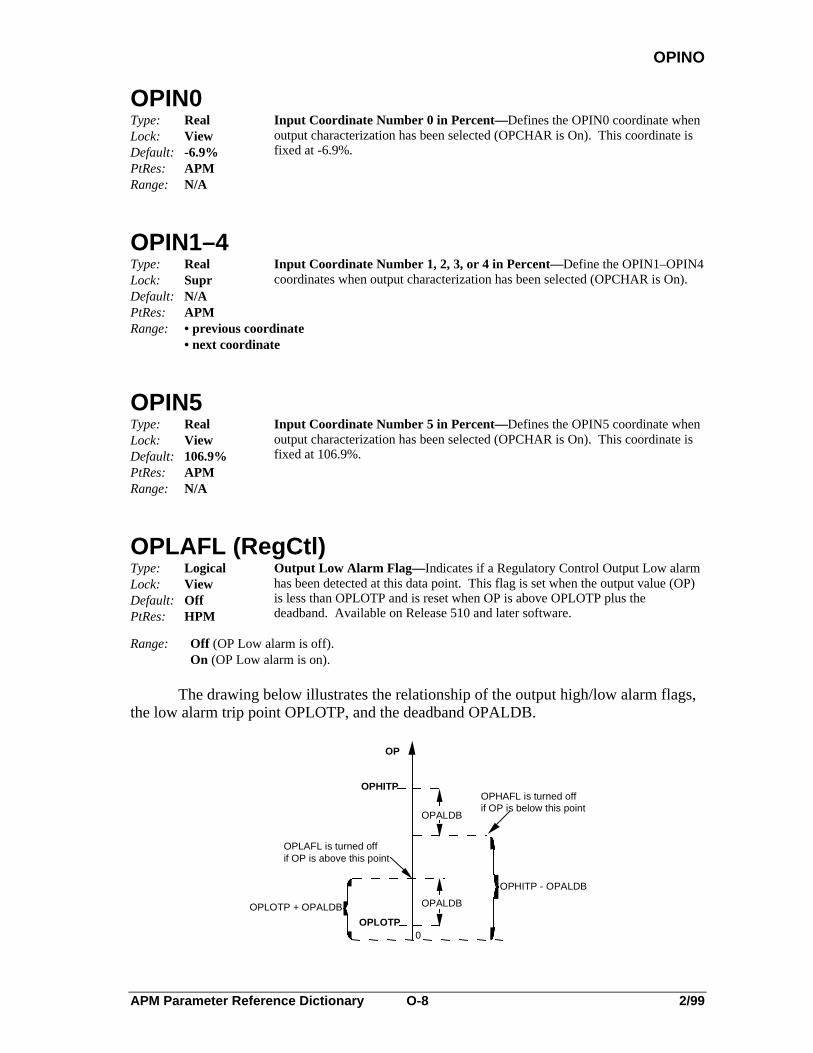
APM Parameter Reference Dictionary O-8 2/99
OPINO
OPIN0Type: RealLock: ViewDefault: -6.9%PtRes: APM
Input Coordinate Number 0 in Percent—Defines the OPIN0 coordinate whenoutput characterization has been selected (OPCHAR is On). This coordinate isfixed at -6.9%.
Range: N/A
OPIN1–4Type: RealLock: SuprDefault: N/APtRes: APM
Input Coordinate Number 1, 2, 3, or 4 in Percent—Define the OPIN1–OPIN4coordinates when output characterization has been selected (OPCHAR is On).
Range: • previous coordinate• next coordinate
OPIN5Type: RealLock: ViewDefault: 106.9%PtRes: APM
Input Coordinate Number 5 in Percent—Defines the OPIN5 coordinate whenoutput characterization has been selected (OPCHAR is On). This coordinate isfixed at 106.9%.
Range: N/A
OPLAFL (RegCtl)Type: LogicalLock: ViewDefault: OffPtRes: HPM
Output Low Alarm Flag— Indicates if a Regulatory Control Output Low alarmhas been detected at this data point. This flag is set when the output value (OP)is less than OPLOTP and is reset when OP is above OPLOTP plus thedeadband. Available on Release 510 and later software.
Range: Off (OP Low alarm is off).On (OP Low alarm is on).
The drawing below illustrates the relationship of the output high/low alarm flags,the low alarm trip point OPLOTP, and the deadband OPALDB.
OPHITP
OPLOTP
OPALDB
OPALDB
0
OPHITP - OPALDB
OPHAFL is turned offif OP is below this point
OPLAFL is turned offif OP is above this point
OPLOTP + OPALDB
OP

APM Parameter Reference Dictionary O-9 2/99
OPLOFL
OPLOFLType: LogicalLock: ProgDefault: OffPtRes: APM
Output Low Limit Flag— Indicates whether the output value OP has reachedthe low limit. This parameter must be set by a program or logic point. It willinhibit "raise" commands.
Range: Off (OP is above the low limit)On (OP has reached the low limit)
OPLOLMType: RealLock: SuprDefault: -5.0%PtRes: APM
Output Low Limit in Percent
Range: -6.9% to OPHILM,NaN
Helpful Hint: Entering NaN disables limit checking by forcing OPLOLM to its extremevalue (-6.9%).
OPLOPR (RegCtl)Type: E:AlpriorLock: EngPBDefault: LowPtRes: NIM
Output Low Alarm Priority— Specifies the priority of the Regulatory ControlOutput Low alarm. Available on Release 510 and later software.
Range: JnlPrint (Alarm is historized and reported to the printer but not annunciated)Printer (Alarm is reported to the printer but not historized and not annunciated)Emergncy (Alarm is historized, annunciated, and reported to all alarm summary displays)High (Alarm is historized, reported to Area Alarm Summary Display and Unit Alarm Summary
Display)Low (Alarm is historized, reported to the Unit Alarm Summary Display, and annunciated)Journal (Alarm is historized but not reported to Universal Stations and not annunciated)NoAction (Alarm is not reported to the system and not annunciated)

APM Parameter Reference Dictionary O-10 2/99
OPLOSRC
OPLOSRCType: UniversalEnt.PrmLock: APMDefault: PtBldPtRes: Null
Output Low Flag Input Source—Indicates which input connection fetches theOPLOFL parameter to determine the windup state.
Range: Use Tagname.Parameter for tagged points where Tagname can be up to 16 characters and thepermissible character set is as follows:
Alphabetics A-Z (uppercase only)Numerics 0-9 (an all numeric tag name is not allowed)Underscore (_) cannot be used as the first character or the last character, and consecutive
underscores are not allowed.Embedded space characters are not allowed.An * is used to default to this point’s tag name.Parameter name can be up to eight characters and must be a legitimate parameter name.
Some possible input-connection sources area."DigIn slot Tagname.PVFL"b."Logic slot Tagname.SO(nn)" where nn = 1–24c."Logic slot Tagname.Fl(nn)" where nn = 1–12d."ProcMod slot Tagname.Fl(nnn)" where nnn = 1–127e."Box Flag slot Tagname.PVFLf."!Box.FL(nnnn)" for a box flag that resides in the same box where nnnn = 1–4095g."$NMhhBxx.FL(nnnn)" for a box flag that resides in a different APM box on the same
UCN; hh is the NIM UCN address, xx is the APM box number, andnnnn = 1–4095 (Data access limit)
Use the hardware reference address !MTmmSss.Parameter for untagged or tagged points whereMT is the IOP type, such as DI (Digital Input)mm is the IOP Card number (1–40)The letter "S" is a constantss is the slot number on the IOP Card (refer to SLOTNUM parameter)Parameter name can be up to eight characters and must be a legitimate parameter name.
OPLOTP(RegCtl)Type: RealLock: SuprDefault: NaNPtRes: APM
Output Low Alarm Trip Point— The Regulatory Control Output Low alarm isset when the output value (OP) drops below the low alarm limit specified byOPLOTP. The alarm is removed when OP returns to normal. A suitable deadband is provided by OPALDB. See also OPLOPR. Available on Release 510and later software.
Range: OPLOLM to OPHITP, NaN
Helpful Hint: The Regulatory Control Output Low alarm is only available for pointsconfigured as full. The alarm is disabled if OPLOTP is not configured.

APM Parameter Reference Dictionary O-11 2/99
OPMCHLM
OPMCHLMType: RealLock: SuprDefault: 0.0PtRes: APM
Output Minimum Change in Percent
Range: > 0.0,NaN
Helpful Hint: OP changes only if new output % - old output % is greater than the percentagein parameter OPMCHLM. Entering NaN disables limit checking by forcingOPMCHLM to its extreme value (0.0).
OPOUT0Type: RealLock: ViewDefault: -6.9%PtRes: APM
Output Coordinate Number 0 in Percent—Defines the OPOUT0 coordinate whenoutput characterization has been selected. (OPCHAR = On) This coordinate isfixed at a value of -6.9%.
Range: N/A
OPOUT1–4Type: RealLock: SuprDefault: N/APtRes: APM
Output Coordinates Number 1, 2, 3, or 4 in Percent—Define the OPOUT1–OPOUT4 coordinates when output characterization has been selected (OPCHARis On).
Range: • previous coordinate• next coordinate
OPOUT5Type: RealLock: ViewDefault: 106.9%PtRes: APM
Output Coordinate Number 5 in Percent—Defines the OPOUT5 coordinate whenoutput characterization has been selected. (OPCHAR = On) This coordinate isfixed at a value of 106.9%.
Range: N/A
OPRATRFLType: LogicalLock: ViewDefault: N/APtRes: APM
Operator Mode Attribute Flag— Indicates whether the current mode attribute isOperator.
Range: Off (Current mode attribute is Program or None)On (Current mode attribute is Operator)
APM Parameter Reference Dictionary O-12 2/99
OPRINPUT
OPRINPUT (ProcMod)
Type: RealLock: OperDefault: 0.0PtRes: APM
Operator Input—Defines the value entered by the operator in response to the lastsequence message.
Range: N/A
OPROCLMType: RealLock: SuprDefault: NaNPtRes: APM
Output Rate of Change Limit in Percent Per Minute
Range: > 0.1NaN
Helpful Hint: Entering NaN disables limit checking.
OPTDIR (AnalgOut)Type: E:POLARITYLock: Eng/PBDefault: DirectPtRes: APM
Analog Output Direct/Reverse Action—Defines the output action of theOPFINAL value of the data point.
Range: 0-Direct (For final OP: 0% = 4 mA; 100% = 20 mA)1-Reverse (For final OP: 0% = 20 mA; 100% = 4 mA)
OPTDIR (DigOut)Type: E:POLARITYLock: Eng/PBDefault: DirectPtRes: APM
Output Direction— Defines the direct/reverse action of the PWM digitaloutput.
Range: 0-Direct (OP is the % On time)1-Reverse (OP is the % Off time)
OROFFSET (ORSel)Type: LogicalLock: Eng/PBDefault: OnPtRes: APM
Override Offset—When OROFFSET is On, override initialization of Pid-typealgorithm points connected to this ORSel algorithm applies an override offsetequal to Gain times Error (PV - SP).
Range: Off (No override offset is applied)On (Offset of Gain times Error is applied)
APM Parameter Reference Dictionary O-13 2/99
OROPT
OROPT (DevCtl, DigComp)Type: LogicalLock: Eng/PBDefault: OffPtRes: APM
Override Option—Allows the operator to bypass permissive and overrideinterlocks by setting BYPASS On.
Range: On (Override option enabled)Off (Override option disabled)
OROPT (ORSel)Type: LogicalLock: Eng/PBDefault: OffPtRes: APM
Override Option—Defines whether the operator can put the point in a bypassstate where any of the X1-X4 inputs can be bypassed. Also, when on, thefeedback value is propagated to nonselected primaries of the override selectoralgorithm. Refer to the APM Control Functions and Algorithms manual for adetailed description.
Range: Off (No override)On (Inputs can be overridden)
OUT0–12 (GenLin)Type: RealLock: SuprDefault: NaNPtRes: APM
Output Coordinates 0 -12—Define the output value at the respective coordinates.
Range: Any value but NaN
OVERFLOWType: LogicalLock: ViewDefault: OffPtRes: APM
Accumulation Overflow Flag—Indicates whether the accumulated value hasoverflowed.
Range: Off (No overflow)On (Overflow)
OVERLAP (Array)Type: IntegerLock: ViewDefault: 0PtRes: APM
Overlapping Array Slot Number—Indicates the Array slot number containing thedata being referenced by the slot currently being built.
Range: 0 through the number of Array slots (NARRSLOT)
APM Parameter Reference Dictionary O-14 2/99
OVERPHAS
OVERPHAS (ProcMod)Type: E:JUMPDIRLock: ONPROC and CNTLLOCK parametersDefault: BlankPtRes: APM
Override Current Phase—Allows the operator to override the current phase ofthe sequence by skipping forward to the next phase, or backward to the previousphase. A phase can be overridden in this manner only when the sequenceexecution state is PAUSE, FAIL, or ERROR.
Range: 0-Forward (Skip to next phase)1-Backward (Go back to previous phase)
OVERSTAT (ProcMod)Type: E:JUMPDIRLock: ONPROC and CNTLLOCK parametersDefault: BlankPtRes: APM
Override Current Statement—Allows the operator to override the currentstatement of the sequence by skipping forward to the next statement, or backwardto the previous statement. A statement can be overridden in this manner onlywhen the sequence execution state is PAUSE, FAIL, or ERROR.
Range: 0-Forward (Skip to next statement)1-Backward (Go back to previous statement)
OVERSTEP (ProcMod)Type: E:JUMPDIRLock: ONPROCDefault: BlankPtRes: APM
Override Current Step—Allows the operator to override the current step of thesequence by skipping forward to the next step, or backward to the previous step.A step can be overridden in this manner only when the sequence execution stateis PAUSE, FAIL, or ERROR.
Range: 0-Forward (Skip to next step)1-Backward (Go back to previous step)

APM Parameter Reference Dictionary O-15 2/99
OVERVAL
OVERVALType: IntegerLock: Eng/PBDefault: 25PtRes: NIM
Overview Value in Percent—Defines the amount of deviation (PV - SP, inpercent) that causes the PV to reach the overview limit. For digital points, thedisplay shows the current state of the point.As shown in Figure O-1, The baseline shows the normal operating value for thisPV.
Range: 0 to 100 (Entering a 0 suppresses the value; value is not shown on the display)
OVERVIEW LIMIT
BASELINE (Normal Value)
DEVIATION TO REACH OVERVIEW LIMIT
Figure O-1 — Overview Limit 1302
OVRCTIM (DevCtl)Type: TimeLock: ViewDefault: 0PtRes: APM
Time Over High Trip Limit— The amount of time the SECVAR parameter iscontinuously greater than the SECVAR high trip limit.
Range: Duration (0 to 9999 days, with a resolution to 1 second)
OVRDALOP (DevCtl,DigComp)Type: E:$OVRALOPLock: Eng/PBDefault: NonePtRes: APM
Override Alarm Option— The override alarm option for I0, I1, and I2parameters.
Range: 0-None (No override alarming)1-Auto_Rtn (Return to normal when override is cleared)2-Cnfm_Rqd (Confirm to clear, after interlock is cleared)

APM Parameter Reference Dictionary O-16 2/99
OVRDALPR
OVRDALPR (DevCtl, DigComp)Type: E:ALPRIORLock: EngrDefault: LowPtRes: APM
Override Alarm Priority— Defines the priority of an override alarm.
Range: JnlPrint (Alarm is historized and reported to the printer but not annunciated)Printer (Alarm is reported to the printer but not historized and not annunciated)Emergncy (Alarm is historized, annunciated, and reported to all alarm summary displays)High (Alarm is historized, reported to Area Alarm Summary Display and Unit Alarm Summary
Display)Low (Alarm is historized, reported to the Unit Alarm Summary Display, and annunciated)Journal (Alarm is historized but not reported to Universal Stations and not annunciated)NoAction (Alarm is not reported to the system and not annunciated)
OVRDCONF (DevCtl, DigComp)Type: LogicalLock: OperDefault: OffPtRes: APM
Override Confirmation Flag— Indicates one of the four override alarmsSI0CONF or I0CONF-I2CONF has not yet been confirmed. This flag is alsoused to confirm the alarm.
Range: Off (An alarm is not waiting for confirmation)On (An alarm is waiting for confirmation)
OVRDDESC (DevCtl, DigComp)Type: String_8Lock: ViewDefault: BlankPtRes: APM
Override Alarm Descriptor— Input connections and logic gating are examined inorder to determine which input was the source of change for the interlock. Forthe Device Control point, descriptor text for this parameter is taken fromLIDESC (1-12). Descriptive text for the Digital Composite point is taken fromSI0 DESC or I0-I2 DESC parameters.
Range: SI0 Desc (Current interlock or input descriptor)I0 - I2 Desc (Current interlock or input descriptor)L1 - L12 Desc (Current interlock or input descriptor, Device Control only)
OVRDI0FL, OVRDI1FL, OVRDI2FL, OVRDSIFL (DevCtl, DigComp)Type: LogicalLock: ViewDefault: OffPtRes: APM
Override and Safety Override Alarm Flag—Indicates that an override is active,or that a confirmable override was cleared, but not yet confirmed.
Range: Off (Override flag is not active)On (Override flag is active)

APM Parameter Reference Dictionary P-1 2/99
P
-P-
P (FlowComp)Type: RealLock: ViewDefault: 1.0PtRes: APM
Pressure Input—Indicates the measured actual gage pressure.
Range: ≥ 0.0
P0(FlowComp)Type: RealLock: SuprDefault: 0.0PtRes: APM
Zero Reference for Pressure—P0 is the zero reference pressure input and is in thesame engineering units as the P input. P0 is typically 14.696 if P is in psig or101.325 if P is in kiloPascals. Enter the absolute value of the number.
Range: N/A
P0–P2 (DevCtl, DigComp)Type: LogicalLock: EngrDefault: OnPtRes: APM
Permissive Interlocks for Output States 0, 1, & 2—Permissive interlocks arecontrolled by logic slot outputs, and each interlock determines whether theoperator and user program are allowed to use the respective state, or are lockedout from that state. A permissive interlock (P0-P2) is provided for each state(STATE0-STATE2). The permissive interlocks themselves never cause theoutputs to change. P0-P2 can be changed by a logic block or a program whenthe point is active and the mode attribute is Program. Refer to the APMControl Functions and Algorithms manual for a detailed description.
Range: Off (Respective state is locked out)On (Respective state is permitted to be used)
Helpful Hint: P0–P2 configuration requires PTEXECST = InActive or PNTSTATE = Idle.
P1–P6 (RegPV)Type: RealLock: ViewDefault: NaNPtRes: APM
PV Inputs 1-6—Indicates the current values at the inputs to the RegPValgorithm. For Totalizers, P2 is the floating point input of AV.
Range: N/A,NaN
P1STS–P6STSType: E:PVVALSTLock: ViewDefault: BadPtRes: APM
P1–P6 Status—Indicate the status of the up to six inputs at the RegPValgorithm.
Range: 0-Bad (Value is bad and replaced with NaN)1-Uncertn (Status of the value is uncertain)2-Normal (Value is good)
PAUSETIM
APM Parameter Reference Dictionary P-2 2/99
PAUSETIM (DevCtl, DigComp)Type: IntegerLock: SuprDefault: 0PtRes: APM
State 0 Pause Time—The amount of time to pause in State 0 on an OP statechange, if the STCHGOPT parameter equals STATE0.
Range: 0 to 1000 seconds
PERIOD (ProcMod, Timer)Type: RealLock: ViewDefault: 1 secondsPtRes: APM
Period—Defines the processing period in seconds.
Range: 1 seconds
PERIOD (DevCtl, DigComp, Logic, RegCtl, RegPV)Type: RealLock: ViewDefault: 1 secondPtRes: APM
Period—Defines the processing period in seconds.
Range: 0.25, 0.5, or 1.0 seconds
PERIOD (DigOut)Type: RealLock: Eng/PBDefault: 10.0 secondsPtRes: APM
Period—Defines length of period for an SO output from DigOut point that hasbeen configured for a PWM output.
Range: 1.0 to 120.0 seconds
PGALGID(1)–(4) (DevCtl)Type: E:$GTALGID in an Array (1..4)Lock: PtBldDefault: NullPtRes: APM
Primary Gate Algorithm ID— Defines the algorithm IDs for primary gates.The Boolean logic gates beginning with “P” have a user-defined pulse size.
Range: NULL (No algorithm)AND (And Gate algorithm)OR (Or Gate algorithm)NAND (Nand Gate algorithm)NOR (Nor Gate algorithm)XOR (Exclusive Or Gate algorithm)PAND (Pulse Nand Gate algorithm)POR (Pulse Or Gate algorithm)PNAND (Pulse Nand Gate algorithm)PNOR (Pulse Nor Gate algorithm)PXOR (Pulse Exclusive-Or Gate algorithm)

APM Parameter Reference Dictionary P-3 2/99
PGDSTN(1)–(4)
PGDSTN(1)–(4) (DevCtl)Type: E:$GATDSTN in an Array (1..4)Lock: PtBldDefault: NonePtRes: APM
Primary Gate Destination—Defines the output destination of the primary gate.
Range: None (No destination)SI0 (Output goes to Safety Interlock)I0, I1, I2 (Output goes to Interlock)P0, P1, P2 (Output goes to Permissives)SOCMD0, SOCMD1, SOCMD2 (Output is commanded to go to SOCMD0, 1 or 2)OPCMD (Output is commanded to go to OPCMD parameter)SG1, SG2 (Output goes to Secondary gates 1 or 2)
PGPLSWTH(1)–(4) (DevCtl)Type: Integer in an Array (1..4)Lock: SuprDefault: 0PtRes: APM
Primary Gate Pulse Width—Indicates the pulse width for primary gates whosealgorithm starts with a “P”.
Range: 0 to 8000 seconds
PGSO(1)–(4) (DevCtl)Type: Logical in an Array (1..4)Lock: ViewDefault: OffPtRes: APM
Primary Gate Status Output—Indicates the output value of the primarygate.
Range: OffOn
PHASE (ProcMod)Type: String_8Lock: ViewDefault: SpacesPtRes: APM
Phase Name—Indicates the current phase of the sequence executing in theprocess module.
Range: N/A
PHASEAL (ProcMod)Type: LogicalLock: ViewDefault: OffPtRes: APM
Phase Alarm—Indicates whether the current phase of the sequence has beencompleted within the specified time.
Range: On (Phase has not been completed in the specified time)Off (No phase alarm)

APM Parameter Reference Dictionary P-4 2/99
PHASETIM
PHASETIM (ProcMod)Type: IntegerLock: ViewDefault: 0 secondsPtRes: APM
Phase Time —Indicates the time remaining in minutes in the current phasebefore a phase alarm is generated. The maximum time allowed for the phase isdefined by the phase statement.
Range: 0 to 9999 minutes
PHREMTIM (ProcMod)Type: TimeLock: ViewDefault: 0 secondsPtRes: APM
Phase Time Remaining—Indicates the time remaining in time duration before aphase alarm is generated. This value is displayed in the APM Detail display.
Range: N/A
PIALGID (1)–(12) (DevCtl)Type: E:$I1ALGID in an Array (1..12)Lock: PtBldDefault: NullPtRes: APM
Primary Input Gate Algorithm ID— The XX algorithms compare this input tothe PINN (1)-(12) parameter, and the IN_SET algorithm compares it to the rangeof 10 values in the NNINSET (1)-(10) parameter. The XX2 algorithms comparethis input defined by the PISRC(1)-(12) parameter.
Range: NULL (No algorithm)INVERT (Invert Logical algorithm)GT (Greater Than algorithm)GE (Greater Than or Equal To algorithm)LT (Less Than algorithm)LE (Less Than or Equal To algorithm)EQ (Equal To algorithm)NE (Not Equal To algorithm)GT2 (Greater Than algorithm)GE2 (Greater Than or Equal To algorithm)LT2 (Less Than algorithm)LE2 (Less Than or Equal To algorithm)EQ2 (Equal To algorithm)NE2 (Not Equal To algorithm)IN_SET (Compares the input to values in the INSET array)
PIDEADBD(1)–(12) (DevCtl)Type: Real in an Array (1..12)Lock: SuprDefault: 1.0PtRes: APM
Primary Input Gate Deadband—The deadband for primary input gates that isconfigured for an arithmetic algorithm.
Range: >0

APM Parameter Reference Dictionary P-5 2/99
PIDFORM
PIDFORMType: E:PIDFORMLock: Eng/PBDefault: InteractPtRes: APM
PID Controller Form— Defines the type of Pid controller form. Refer to theAPM Control Functions and Algorithms manual for a detailed description.
Range: 0-Interact [(Proportional + Integral) x Derivative]1-Ideal (Proportional + Integral + Derivative)
PIDSTN(1)-(6)Type: Ent.PrmLock: ViewDefault: Based on
PVALGID,PVEQN, & N
PtRes: APM
PV Input Connection Destination—Defines the parameter in the data point thatis to receive the value provided by the respective input connection. There can beup to six input-connection destinations for a RegPV point.
Range: 1–8 character valid parameter name
PINN (1)–(12) (DevCtl)Type: RealLock: SuprDefault: 0.0PtRes: APM
Primary Input Constants Numeric—The numeric constant for arithmeticcomparisons of primary input gates using XX algorithms.
Range: <> NaN
PISO (1)–(12) (DevCtl)Type: Logical in an Array (1..12)Lock: ViewDefault: OffPtRes: APM
Primary Input Gate Output Value— Indicates the output value of the primary inputgate.
Range: OffOn
PISRC(1)–(12) (DevCtl)Type: E:$GATESRC in an Array (1..12)Lock: PtBldDefault: NullPtRes: APM
Primary Input Source—The source for the second input of primary input gates forarithmetic comparison algorithms that use a second external input (i.e., XX2algorithms).
Range: NULL (No source for input)L1..L12 (These values correspond with the LISRC(1)—(12) parameter)

APM Parameter Reference Dictionary P-6 2/99
PISRC(1)-(6)
PISRC(1)–PISRC(6)Type: Ent.PrmLock: PtBldDefault: null.nullPtRes: APM
PV Input Connection Source—Define the parameters whose current values are tobe fetched and then written to the up to six RegPV algorithm inputs. Thesource parameter name can be specified using the "Tagname.Parameter" format.Refer to the APM Control Functions and Algorithms manual for a detaileddescription.
Range: Use Tagname.Parameter for tagged points where Tag name can be up to 16 characters and thepermissible character set is as follows:Alphabetics A-Z (uppercase only)Numerics 0-9 (an all numeric tag name is not allowed)Underscore (_) cannot be used as the first character or the last character, and consecutive
underscores are not allowed.Embedded space characters are not allowed.An * is used to default to this point’s tag name.Parameter name can be up to eight characters, and must be a legitimate parameter name.
PIUOTDCF (STI, LLMUX, RHMUX)
Type: LogicalLock: Eng/ViewDefault: OnPtRes: APM
Open Thermocouple Detection Enable—Defines whether the point is to detect anopen thermocouple condition. This parameter is configurable for each STI pointthat is connected to a smart temperature transmitter and for each LLMUX point.NOTE: There is no special point type for RHMUX. The LLMUX point typealso applies to the RHMUX IOP.
This parameter is a view-only parameter when the point execution statePTEXECST is Active.
Range: On (Detect an open thermocouple condition)Off (Do not detect an open thermocouple)
PIUOTDCF(1)–(168) (LLAI)Type: LogicalLock: SuprDefault: OnPtRes: APM
LLAI Open Sensor Detection Enable—Defines whether anopen-sensor condition is to be detected for all eight LLAI points.
Range: On (Detect open-sensor conditions)Off (Do not detect open-sensor conditions)

APM Parameter Reference Dictionary P-7 2/99
PKGOPT
PKGOPT (APM Box)Type: E:$PKGOPTLock: PtBldDefault: REDUNPtRes: APM
APMM Hardware Packaging Option. The tables below show the defaulthardware location for each choice.
Range: 0-NONREDUN (APMM is not redundant; can have up to 40 I/O Modules)1-REDUN (Redundant APMMs in the same file; can have up to 40 I/O Modules)2-REDUN_2F (Redundant APMMs in two separate files; can have up to 40 I/O Modules)3-REDUN_IO(Redundant APMMs/two separate files/can have full redundant IOPs)4-NODEFALT (Sets file/card positions of IOPs to 0). On download to the APM, changes to NONREDUN, REDUN, or REDUN_2F based on actual hardware.
Helpful Hints: Parameter NODENUM must be equal to an odd number no matterwhich option is selected for PKGOPT.
During Node Specific configuration, if you choose Nonredund or Redun_IO, you must type infile and card numbers for the I/O cards. Refer to the tables below or the APM Node SpecificConfiguration Form if necessary.
NONREDUN REDUNHardware File Card Slot Hardware File Card Slot
APMM 1 1 - 5 APMM’s 1 1 – 10IOM-A 1 – 10 1 6 - 15 IOM-A 1 - 5 1 11 – 15IOM-A 11 – 25 2 1 - 15 IOM-A 6 - 20 2 1 – 15IOM-A 26 – 40 3 1 - 15 IOM-A 21 - 35 3 1 – 15
IOM-A 36 - 40 4 1 – 5
REDUN_2F REDUN_I/OHardware File Card Slot Hardware File Card SlotPrimary APMM 1 1 - 5 Primary APMM 1 1 - 5Secondary APMM 2 1 - 5 Secondary APMM 2 1 - 5IOM-A 1 – 10 1 6 - 15 IOM-A 1 - 10 1 6 - 15IOM-A 11 – 20 2 6 - 15 IOM-A 11 - 25 3 1 - 15IOM-A 21 – 35 3 1 - 15 IOM-A 26 - 40 5 1 - 15IOM-A 36 – 40 4 1 - 5 IOM -B 1 - 10 2 6 - 15
IOM -B 11 - 25 4 1 - 15IOM -B 26 - 40 6 1 - 15

APM Parameter Reference Dictionary P-8 2/99
PMEVOVFL
PMEVOVFLType: LogicalLock: ViewDefault:PtRes: APM
APMM Event Overflow Flag
Range: Off (No overflow)On (Overflow has occurred)
PMMCHAER (APM Box)Type: IntegerLock: ViewDefault: 0PtRes: APM
APMM I/O Link Channel A Error Count
Range: > 0
PMMCHASL (APM Box)Type: IntegerLock: ViewDefault: 0PtRes: APM
APMM I/O Link Channel A Silence Count
Range: > 0
PMMCHBER (APM Box)Type: IntegerLock: ViewDefault: 0PtRes: APM
APMM I/O Link Channel B Error Count
Range: > 0
PMMCHBSL (APM Box)Type: IntegerLock: ViewDefault: 0PtRes: APM
APMM I/O Link Channel B Silence Count
Range: > 0

APM Parameter Reference Dictionary P-9 2/99
PMMCMD
PMMCMD (APM Box)Type: E:$PMMCMDLock: OnProcDefault: NonePtRes: APM
APMM Command
NOTE
When points are built to a NIM and the NIM is restarted with no database, the points needto be reloaded from checkpoint or the points must be reconfigured. If the database is tobe reconfigured, the APMM must be in Idle, and the point execution state must be Inactive.This allows the point build operation to override the database that already exists there.
Range: 0-None (No command request has been issued)1-Run (To "Run" state for processing points)2-Idle (To "Idle" state for reloading the database)3-RsIoLCom (Reset I/O Link communication error count = 0)4-ShutDown (To "Alive" state for reloading personality)5-RsUcnLsb (Reset the Local Statistics Block to zeroes)6-SelChnA (Select Input/Output Link Channel A)7-SelChnB (Select Input/Output Link Channel B)8-Warmstrt (Warm Start)9-Coldstrt (Cold Start)
10-SwapPri (Switchover to the redundant APMM)
PMMCOMER (APM Box)Type: E:$IOMCOMMLock: ViewDefault: N/APtRes: APM
APMM I/O Link Communication Error Status
Range: 0-None (No communication errors)1-InvAlert (Invalid Alert—message bit problem)2-InvDest (Invalid Destination)3-InvChCnt (Invalid Character Count)4-InvSourc (Invalid Source)5-InvCmd (Invalid Command)6-Checksum (Data record Checksum Error)7-No_Resp (No Response)8-ChTimOut (Channel Time Out)9-MsgOvRun (Message Overrun)
10-GapError (Message gap is too long)11-LpBckErr (Loop Back Error)12-NTH_0 (Next Token Holder equals zero)13-TknRecov (Token Recovery in progress)14-RplBufOv (Reply Buffer Overflow)

APM Parameter Reference Dictionary P-10 2/99
PMMCTLSTPMMCTLST (APM Box)Type: LogicalLock: ViewDefault: OffPtRes: APM
APMM Control Processor Status
Range: Off (Control processor has not failed)On (Control processor has failed)
PMMIOLST (APM Box)Type: E:$IOMSTSLock: ViewDefault:PtRes: APMRange: Notconfg (IOP not configured)
Confgmis (Configuration mismatch detected)OK (Module is running with no soft fail errors)Idle (Module is idle with no soft fail errors)Softfail (Module is running with soft fail error(s) present)Idlesf (Module is idle with soft failure error(s) present)Nonexist (Module does not exist at this address)Noresp (No response from module)Poweron (Module state is Power On)Commerr (Communication error to IOP)Unavail (Module is unavailable for communication)
PMMOPER (APM Box)Type: E:$OPERATELock: ViewDefault: N/APtRes: APM
Process Manager Module Operation—Indicates the type of APMM.
Range: 0-NonRedun (This APMM has no redundant APMM to back it up)1-Primary (This APMM is the primary point processor)2-Secondry (This APMM is the secondary APMM that backs up the primary APMM)
PMMRECCH (APM Box)Type: E:$RECCHNLock: ViewDefault: N/APtRes: APM
APMM I/O Link Current Receive Channel
Range: 0-ChannelA (Channel A is channel currently receiving)1-ChannelB (Channel B is channel currently receiving)
PMMRECHNType: E:$RECCHNLock: ViewDefault: N/APtRes: APM
APMM Active Receive Channel
Range: ChannelAChannelB
APM Parameter Reference Dictionary P-11 2/99
PMMSFST
PMMSFST(1)–(96)Type: LogicalLock: ViewDefault:PtRes: APM
APMM Soft Failure
Range: OffOn
PMMSTS (APM Box)Type: E:$NODESTALock: ViewDefault: N/APtRes: APM
APMM Primary Status
Range: 0-OffNet (NIM cannot communicate with the APMM)1-ConfgMs (Configuration mismatch detected)2-Idle (Event reports but no point processing)3-IdleSF (Soft failure occurred in Idle state)4-OK (APMM is operating normally)5-SoftFail (Soft failure while APMM is running)6-Fail (APMM can be accessed but CPU is halted; box hard failure has been detected )10-Alive (No event reports or point processing)11-AliveSF (Soft failure during Idle state)12-Test (APMM is in the test mode)13-TestSF (Soft failure has been detected while the APMM is in the test mode)15-Loading (Personality or data base is loading)16 S_Idle (Idle in IOSM)17 S_Idle SF (IdleSF in IOSM)18 S_OK (OK in IOSM)19 S_SFFail (SoftFail in IOSM)20 S_Pause (HPM is in the Simulation Pause state)
Helpful Hint: Loading the APMM’s operating personality software requires PMMSTS = Alive.Loading the APMM’s database requires PMMSTS = Idle. Use parameterPMMCMD’s "Shutdown" and "Idle" command requests, respectively.
APM Parameter Reference Dictionary P-12 2/99
PNTFORM
PNTFORMType: E:$PNTFORMLock: View/PBDefault: FullPtRes: APM
Point Form—Defines the form of the data point that is implemented. Referto the APM Control Functions and Algorithms manual for a detaileddescription of this function.
Range: 0-Full (Point is fully displayed and alarmed)1-Componnt (Point is partially displayed but not alarmed)
Helpful Hint: This parameter is not applicable to DigOut points. For unconfigured DigIn andAnalogOut points (used for Hardware Reference Addressing; see xPMParameter Reference Dictionary), the default value is Component.
PNTMODTYType: E:$PMMDTYLock: ViewDefault: N/APTRes: NIM
Point's Module Type—Defines where the data point resides. Control pointssuch as DigComp, RegPV, RegCtl, Logic, Process Module, Array, BoxFlags, Box Numerics, and Box Timers reside in the APMM.
Range: AO (Analog Output)AO_16 (Analog Output 16 point)DI (Digital Input)DO (Digital Output)DO_32 (Digital Output 32 point)HLAI (High-Level Analog Input)LLAI (Low-Level Analog Input)STIM (Smart Transmitter Interface)NotConfg (Not Configured)PI (Pulse Input)APMM (Advanced Process Manager Module)LLMUX (Low-Level Analog Input Multiplexer) All references to LLMUX also apply to
RHMUX, except that RHMUX does not support SENSRTYP of RTD.DISOE (Sequence of Events)SI (Serial Interface)
PNTNODTYType: E:$UCNNDTY Point's Node Type—Defines the type of node on the UCNLock: ViewDefault: N/APtRes: NIMRange: NIM (Network Interface Module)
APM (Advanced Process Manager)NotConfg (Node not configured)
PNTSTATEType: E:PNTSTATELock: ViewDefault: N/APtRes: NIM
Point's Overall State—Defines the state of the data point, which is based onthe state of the APMM and the IOP Card in which it resides.
Range: Failed (NIM cannot communicate with point’s APMM/IOP)Idle (Point’s APMM or IOP is in the Idle State)OK (Point’s APMM or IOP is the Run State and is OK)
Uncertn (Point’s APMM or IOP is uncertain)
APM Parameter Reference Dictionary P-13 2/99
PNTTYPE
PNTTYPEType: E:PNTTYPELock: PtBldDefault: NullPtRes: APM
Point Type—Defines the type of point in the APM.
Range: 0-Null (Not configured)1-AnalgIn (Analog Input)2-AnalgOut (Analog Output)4-DigIn (Digital Input)5-DigOut (Digital Output)6-DigCom (Digital Composite)8-RegPV (Regulatory PV)9-RegCtl (Regulatory Control)
10-Logic (Logic)11-Array (Array)12-Flag (Flag)13-Numeric (Numeric)14-ProcModl (Process Module)22-Timer (Timer)28-DevCtl (Device Control)
Helpful Hint: PNTTYPE of DigOut has a restriction that PNTFORM cannot be = Full.
POSITION (APM Box)Type: E:$POSITINLock: ViewDefault: N/APtRes: APM
APMM File Position
Range: 0-Right (APMM cards are in card file slots 6–10)1-Left (APMM cards are in card file slots 1–5)2-File_1 (APMM cards are in card file 1)3-File_2 (APMM cards are in card file 2)4-Pref5-Non_Pref 6-None 7-Unknown (Not able to determine file position from hardware)
PR2PREFF (APM Box)Type: RealLock: ViewDefault: 100PtRes: APM
Peer-to-Peer Communication Efficiency (in percent)—Indicates the rate ofsuccessful and on time UCN transactions from this node.
Range: 0 - 100
Helpful Hint: This statistic is displayed on the Control Configuration page of the APM Diagnostic Display.

APM Parameter Reference Dictionary P-14 2/99
PRIMMOD
PRIMMODType: Ent_IdLock: EngrDefault: NullPtRes: NIM
Primary Module Identifier— Typically used in Batch Processing, this parametercontains the tag name of an APM point to which this data point is assigned.Other points that belong to the Batch Equipment Unit should have theirPRIMMOD set to this same point. Primmod is used to collect alarms andevents from this point along with others related to the specified Primary Modulepoint. Information is collected into a common file, accessible from the EventHistory Menu.
Range: Tag name of the process module point can be up to 16 characters, and the permissible characterset is as follows:Alphabetics A-Z (uppercase only)Numerics 0-9 (an all numeric tag name is not allowed)Underscore (_) cannot be used as the first character or the last character, and consecutive
underscores are not allowed.Embedded space characters are not allowed.
Helpful Hint: For Box Flag points, this parameter applies to only slots 1 through 128.LCN entities that can be stored to PRIMMOD in NIM points are restricted to local NIM points.
PRMDESC(1)–(12) (Logic)Type: E:$PMMLGPMLock: Eng/PBDefault: N/APtRes: NIM
Parameter Descriptor Assignment—Defines up to 12 logic-slot parametersto which custom generic descriptors entered through parametersGENDESC(1-12) are to be assigned.
Range: L1...L12 (Logic-slot inputs)FL1...FL12 (Logic-slot flags)NN1...NN8 (Logic-slot numerics)SO1...SO24 (Logic-slot outputs)
PROCMOD (ProcMod)Type: E:PROCMODLock: Determined by CNTLLOCK parameterDefault: OffPtRes: APM
Process Module Operating State—Represents the operational condition ofa process module. Refer to the APM Control Functions and Algorithmsmanual for a state diagram.
Range: 0-Off (Off)2-Norm (Normal)4-Hold (Hold)5-Shdn (Shutdown)6-Emsd (Emergency Shutdown)7-Strt (Start)8-Stop (Stop)

APM Parameter Reference Dictionary P-15 2/99
PRPMMSTS
PRPMMSTSType: E:$NODESTALock: ViewDefault:PtRes: APM
Previous APMM Status
Range: Offnet (APMM is offnet with no communications possible)Confgmis (APMM is in configuration mismatch)Idle (APMM is idle)Idlesf (APMM is idle with soft failure(s))OK (APMM is running with no errors)Softfail (APMM is running with soft failure(s))Fail (APMM has failed)Poweron (APMM is in Power On state-startup condition from power loss)Alive (APMM has passed self diagnostics and is ready to accept personality)Alivesf (APMM diagnostics have soft failure)Loading (APMM is loading personality)Notconfg (APMM is not configured on network)Unavail (APMM is unavailable on network for communications)Test (APMM is in Test mode)Testsf (APMM is in Test mode with a soft failure(s))
APM Parameter Reference Dictionary P-16 2/99
PRVCOMFL
PRVCOMFLType: E:$PMMHFSTLock: ViewDefault:PtRes: APM
Previous APMM Communications Board Failure
Range: NULL (Unknown Error)PWRDWN (Power is Off)LR_PAR (Local Ram Parity Error)LR_LRAM (Local Ram Error)LR_CK (Local Ram Check)LR_EXC (Local Ram Exception )LR_HREV (Local Ram Hardware Revision)MM_HREV (Memory Board Hardware Revision)LR_TMR (Local Ram Timer Error)LR_PTRN (Local Ram Pattern Check Error)LR_BYTE (Local Ram Byte Error)LR_ADCD (Local Ram Address Decode Test)LR_ADDL (Local Ram Additional Checks)LR_CLRR (Local Ram Scrub Incomplete)SR_PAR (Shared Ram Parity)SR_PTRN (Shared Ram Pattern)SR_ADCD (Shared Ram Address Decode Test)SR_ADDL (Shared Ram Additional Checks)GR_PAR (Global Ram Parity)GR_PTRN (Global Ram Pattern Check Error)GR_BYTE (Global Ram Byte Error)GR_ADCD (Global Ram Address Decode Test)GR_ADDL (Global Ram Additional Checks)GR_CLRR (Global Ram Scrub Incomplete)31_NR (IOL Processor, No Response or Failure)31_ALIV (IOL Processor, Transmitter Not Alive)31_ILTN (IOL Processor, Illegal Transition)NMI_UNK (Unknown NMI Request)BADUCNN (UCN Address Parity or Duplicate Address)NR (No Response From Other Processor)MRFT (Memory Reference Table - Pattern Build Fail)NOMTOS (No MTOS Readout)LLC_COMM (LLC Communication Fatal Error)UCNDRV (UCN Driver, Fatal Error)RD_HREV (Redundancy Card Version/Revision Mismatch)SW_ERROR (Software Error)MD_HREV (Modem Card Version/Revision Mismatch)DA_PTRN (Daughter Card Pattern Test)DA_BYTE (Daughter Card Byte Write Test)DA_ADCD (Daughter Card Address Decode)DA_ADDL (Daughter Card Additional Tests)DA_CLRR (Daughter Card Scrub Incomplete)RD_SNPS (Redundancy Card 96 Kw Snapshot Error)RD_BSLK (Redundancy Card Bus Lock Fail)
APM Parameter Reference Dictionary P-17 2/99
PRVCTLFL
PRVCTLFLType: E:$PMMHFSTLock: ViewDefault:PtRes: APM
Previous APMM Control Failure
Range: NULL (Unknown Error)PWRDWN (Power is Off)LR_PAR (Local Ram Parity Error)LR_LRAM (Local Ram Error)LR_CK (Local Ram Check)LR_EXC (Local Ram Exception )LR_HREV (Local Ram Hardware Revision)MM_HREV (Memory Board Hardware Revision)LR_TMR (Local Ram Timer Error)LR_PTRN (Local Ram Pattern Check Error)LR_BYTE (Local Ram Byte Error)LR_ADCD (Local Ram Address Decode Test)LR_ADDL (Local Ram Additional Checks)LR_CLRR (Local Ram Scrub Incomplete)SR_PAR (Shared Ram Parity)SR_PTRN (Shared Ram Pattern)SR_ADCD (Shared Ram Address Decode Test)SR_ADDL (Shared Ram Additional Checks)GR_PAR (Global Ram Parity)GR_PTRN (Global Ram Pattern Check Error)GR_BYTE (Global Ram Byte Error)GR_ADCD (Global Ram Address Decode Test)GR_ADDL (Global Ram Additional Checks)GR_CLRR (Global Ram Scrub Incomplete)31_NR (IOL Processor, No Response or Failure)31_ALIV (IOL Processor, Transmitter Not Alive)31_ILTN (IOL Processor, Illegal Transition)NMI_UNK (Unknown NMI Request)BADUCNN (UCN Address Parity or Duplicate Address)NR (No Response From Other Processor)MRFT (Memory Reference Table - Pattern Build Fail)NOMTOS (No MTOS Readout)LLC_COMM (LLC Communication Fatal Error)UCNDRV (UCN Driver, Fatal Error)RD_HREV (Redundancy Card Version/Revision Mismatch)SW_ERROR (Software Error)MD_HREV (Modem Card Version/Revision Mismatch)DA_PTRN (Daughter Card Pattern Test)DA_BYTE (Daughter Card Byte Write Test)DA_ADCD (Daughter Card Address Decode)DA_ADDL (Daughter Card Additional Tests)DA_CLRR (Daughter Card Scrub Incomplete)RD_SNPS (Redundancy Card 96 Kw Snapshot Error)RD_BSLK (Redundancy Card Bus Lock Fail)

APM Parameter Reference Dictionary P-18 2/99
PRVIOLFL
PRVIOLFLType: E:$IOMHFLock: ViewDefault:PtRes: APM
Previous IOL Failure
Range: UNKNOWN (Unknown Error)POWERDWN (Power is Off)INVPRGEX (Invalid Program Execution)EPROMERR (EPROM Error)RAMCNTER (Ram Contents Error)RAMADRER (Ram Address Error)DPAERROR (Physical Address Error)DSAERROR (Soft Address Error)RXBUFOFL (Receive Buffer Overflow)IOLJABER (IOL Jabber Circuit - saw too much traffic)BADPGJMP (Bad Program Jump)ADCINCMP (A/D Incomplete)ADOUTOVF (A/D Output Overflow)ADOUTUDF (A/D Output Underflow)ADCCALER (A/D Calibration Error)BADDCLTC (Bad DC LTC)DMT_TMOT (Dead Man Time Out)MLTOUTFL (Multiple Output Failure)DATBUSFL (Data Bus Failure)BADDARNG (Bad D/A Range)MSTRTMOT (Master Time Out 68 K)CTRCKTFL (Counter Circuit Failure)
PSTS (FlowComp)Type: E:PVVALSTLock: ViewDefault: NormalPtRes: APM
Pressure Input Value Status—Status of the P input value.
Range: 0-Bad (Value is bad and replaced with NaN)1-Uncertn (Status of the value is uncertain)2-Normal (Value is good)
PTDESCType: String_24Lock: PtBldDefault: BlankPtRes: NIM
Point Descriptor—A 24-character descriptor which is used to describe the pointand appears on the Group and Detail Displays for the point. Refer toFigure N-1.
Range: Permissible character set consists of all characters on the Engineer’ s Keyboard. Basically this setconsists of alphabetics A-Z, numerics 0-9, and the following special characters: space ! % & ’( ) * + - / : ; > < = ? _ , . $
APM Parameter Reference Dictionary P-19 2/99
PTEXECST
PTEXECSTType: E:PTEXECSTLock: SuprDefault: InactivePtRes: APM
Point Execution State—Defines the current execution state of the point.
Range: 0-Inactive (Point is not scanned or processed)1-Active (Point is scanned and processed)
PTINAL (RegCtl, RegPV)Type: LogicalLock: ViewDefault: OffPtRes: APM
Point in Alarm Indicator— Indicates when an alarm condition has been detected atthis point.
Range: Off (Point is not in alarm)On (Point is in alarm)
PTORST (RegCtl)Type: E:ORSTATUSLock: ProgDefault: NotConPtRes: APM
Point Override Status—Indicates the override status of the point.
Range: 0-NotCon (Not connected to ORSel algorithm. Also indicates that point has been returned from inactive to active status, or it is undergoing a cold restart, or it is being initialized.)
1-Sel (Selected as a part of ORSel strategy)2-NotSel (Not selected as a part of ORSel strategy)
PTSTSIOLType: E:$NODESTALock: ViewDefault:PtRes: APM
Redundant Partner Status as Seen From the IOL
Range: OffNet (NIM cannot communicate with the APMM)ConfgMis (Configuration mismatch detected)Idle (Event reports but no point processing)Idlesf (Soft failure occurred in Idle state)Ok (APMM is operating normally)SoftFail (Soft failure while APMM is running)Fail (APMM can be accessed but CPU is halted; box hard failure has been detected)Powron (Power is on)Alive (No event reports or point processing)Alivesf (Soft failure during Idle state)Test (APMM is in the Test mode)TestSF (Soft failure has been detected while the APMM is in the Test mode)Loading (Personality or database is loading)NotconfgNosynchUnavail

APM Parameter Reference Dictionary P-20 2/99
PTSTSUCN
PTSTSUCNType: E:$NODESTALock: ViewDefault:PtRes: APM
Redundant Partner Status as Seen From the UCN
Range: Offnet (NIM cannot communicate with the APMM)Confgms (Configuration mismatch detected)Idle (Event reports but no point processing)Idlesf (Soft failure occurred in Idle state)Ok (APMM is operating normally)Softfail (Soft failure while APMM is running)Fail (APMM can be accessed but CPU is halted; box hard failure has been detected)Powron (Power is on)Alive (No event reports or point processing)Alivesf (Soft failure during Idle state)Test (APMM is in the Test mode)Testsf (Soft failure has been detected while the APMM is in the Test mode)Loading (Personality or database is loading)NotconfgNosynchUnavail
PULSEWTH (DevCtl, DigComp)Type: RealLock: SuprDefault: 1.0 secondPtRes: APM
Pulse Width for Point Outputs
Range: 0.0 to 60.0 seconds
Helpful Hint: PULSEWTH change requires DODSTN= "Tagname.ONPULSE" or OFFPULSE. When On is to be written to the DigOut module, a pulse of thespecified width is generated. When Off is to be written, no pulse is generated.
PV (AnalgIn, PI)Type: RealLock: OperDefault: NaNPtRes: APM
Process Variable—PV is the PV’s current value after the PV is selected from oneof the following possible sources: a field device, an operator, or a program. SeePVSRCOPT and PVSOURCE.
Range: PVEXEUHI to PVEXEULO,NaN
Helpful Hint: PV change by a program requires PVSRCOPT = All and PVSOURCE = Sub.PV change by an operator requires PVSRCOPT = All and PVSOURCE = Man.
APM Parameter Reference Dictionary P-21 2/99
PV
PV (DevCtl, DigComp)Type: E:SD_ENM:PVSTATESLock: OperDefault: BADPVTXTPtRes: APM
Current State—PV is the PV’s current state after the PV is selectedfrom one of the following possible sources: a field device, anoperator, a program, or the output of the PV’s data point. SeePVSRCOPT and PVSOURCE.
Range: 0-PVSTATES (0) (Defined by STATETXT (0))1-PVSTATES (1) (Defined by STATETXT (1))2-PVSTATES (2) (Defined by BADPVTXT)3-PVSTATES (3) (Defined by MOVPVTXT)4-PVSTATES (4) (Defined by STATETXT(2))
Helpful Hint: PV change by a program requires PVSRCOPT = All and PVSOURCE = Sub.PV change by an operator requires PVSRCOPT = All and PVSOURCE = Man.
PV (DigIn)Type: E:SD_ENM:STATETXTLock: OperDefault: OffPtRes: APM
Current State—Indicates the current state of the PV input to thisdata point. Not appropriate if DITYPE = ACCUM.
Range: STATETXT(0) or STATETXT(1)
Helpful Hint: PV is derived from the open or closed state of field contacts and from theconfigured direct or reverse input direction (INPTDIR).
PV change by a program requires DITYPE = Latched or status,PVSRCOPT = All, and PVSOURCE = Sub.PV change by an operator requires DITYPE = Latched or status,PVSRCOPT = All, and PVSOURCE = Man.
PV (Flag)Type: E:SD_ENM:STATETXTLock: OperDefault: BlankPtRes: APM
Current State—Indicates the current state of the flag data point, andit is derived from PVFL. STATETXT(1) is the alarmed state.
Range: STATETXT(0) or STATETXT(1)
PV (Numeric)Type: RealLock: OperDefault: NaNPtRes: APM
Process Variable—Indicates the value of the numeric. This value maps intoparameter NN(n) in the APM box where n = SLOTNUM.
Range: N/A
APM Parameter Reference Dictionary P-22 2/99
PV
PV (RegCtl, RegPV)Type: RealLock: View for
RegCtl,Oper forRegPV
Default: NaNPtRes: APM
Process Variable—Indicates the current value of the PV after the PV is selectedfrom one of the following possible sources: a field device, an operator, or aprogram. See PVSRCOPT and PVSOURCE.
Range: N/A
Helpful Hint: PV change by a program requires PVSRCOPT = All and PVSOURCE = Sub.PV change by an operator requires PVSRCOPT = All and PVSOURCE = Man.
PV (Timer)Type: IntegerLock: ViewDefault: 0PtRes: APM
Current Value—Indicates the current time in seconds or minutes. The timerstarts at 0 and is incremented towards the preset time established by the SPparameter.
Range: 0 to 32000
PVALDB (RegCtl, RegPV)Type: E:PVALDBLock: Eng/PBDefault: OnePtRes: APM
PV Alarm Deadband—Alarm deadband is used to prevent excessive recurrence ofalarms by adjusting the percent of Engineering Unit range at which the alarm"returns to normal."
Range: 0-Half (1/2 of 1% of Engineering Unit range)1-One (1% of Engineering Unit range)2-Two (2% of Engineering Unit range)3-Three (3% of Engineering Unit range)4-Four (4% of Engineering Unit range)5-Five (5% of Engineering Unit range)6-EU (Specify deadband in Engineering Units)
PVALDBEU (RegCtl, RegPV)Type: Real EU value of alarm deadbandLock: Eng/PBDefault: NaNPtRes: APMRange: > 0.0
APM Parameter Reference Dictionary P-23 2/99
PVALGID
PVALGIDType: E:$PMMPVAGLock: PtBldDefault: NullPtRes: APM
PV Algorithm Identifier— Defines which PV algorithm is to be used for aRegPV point.
Range: 0-Null (No algorithm configured)1-DataAcq (Data Acquisition)2-FlowComp (Flow Compensation)3-MidOf3 (Middle-Of-3 Selector)4-HiLoAvg (High Low Average Selector)5-Summer (Summer)6-VdtLdLag (Variable Dead Time with Lead Lag)7-TotaLizr (Totalizer)8-GenLin (General Linearization)9-Calcultr (Calculator)
PVAUTO (AnalgIn, PI)Type: RealLock: ViewDefault: NaNPtRes: APM
PV Auto Value—Value of the PV after PVCALC is range checked, filtered, andclamped.
Range: N/A
PVAUTO (DevCtl, DigComp)Type: E:PVSTATESLock: ViewDefault: BADPVTXTPtRes: APM
Current PV State—Indicates the current PV state, based on the states of theinputs to the point.
Range: 0-STATETXT(0)1-STATETXT(1)2-BADPVTXT3-MOVPVTXT4-STATETXT(2) (only if NOSTATES is 3)
PVAUTO (DigIn)Type: E:STATETXTLock: ViewDefault: N/APtRes: APM
Current PV State—Indicates the current PV state that corresponds to the fieldcontact input after direct/reverse correction.
Range: STATETXT(0) or STATETXT(1)
APM Parameter Reference Dictionary P-24 2/99
PVAUTO
PVAUTO (RegCtl)Type: RealLock: ViewDefault: NaNPtRes: APM
PV Auto Value Fetched Using Control Input Connection—Indicates the currentvalue of the PV when the RegCtl point is in the Auto mode.
Range: N/A
PVAUTO (RegCtl, RegPV)Type: RealLock: ViewDefault: NaNPtRes: APM
PV Auto Value—Indicates the current value of the PV after the algorithmcalculation is performed, the range is checked, and the PV is filtered and clamped.
Range: N/A
PVAUTOST (RegCtl, RegPV)Type: E:PVVALSTLock: ViewDefault: BadPtRes: APM
PV Auto Value Status—Indicates the current status of the PVAUTO value.
Range: 0-Bad (All inputs, or result in PVCALC is bad)1-Uncertn (Final result in PVCALC is an uncertain value)2-Normal (Final result in PVCALC is a normal value)
PVCALC (AnalgIn, PI)Type: RealLock: ViewDefault: NaNPtRes: APM
Calculated PV—PVCALC is the PV value in Engineering Units after the rawPV (PVRAW) input to this data point has been characterized. The value ofPVRAW is the PV value provided by the Field Termination Assembly (FTA).
Range: PVEXEUHI to PVEXEULO,NaN
PVCALC (RegPV)Type: RealLock: ViewDefault: NaNPtRes: APM
Calculated PV—Indicates the value of the PV after the PV has been calculated bythe PV algorithm.
Range: N/A,NaN

APM Parameter Reference Dictionary P-25 2/99
PVCHAR
PVCHARType: E:VALCHARLock: PtBldDefault: LinearPtRes: APM
PV Characterization Option—Defines the display characterization to beused for characterizing the input PV value. Characterization is based on thefield sensor type.
HLAI, LLMUX, RHMUX, & LLAI — PV Characterization
X = Allowable Sensor Type (SENSRTYP)
Range
PNTMODTY(NOTE1)
pt4-2V
0-2V
1-5V
0-100mV
TC
Slidewire
RTD
Valid normalrange
(PVEULO–PVEUHI)
in Degrees C(when TCRNGOPT
= Normal forSENSRTYP =
Thermcpl
Valid extendedrange
(PVEXEULO–PVEXEUHI)in Degrees C
(when TCRNGOPT= Extended forSENSRTYP =
Thermcpl)0-Jtherm HLAI
LLAILLMUX
X X XXX
-200 to 1200-100 to 750-100 to 750
N/A-200 to 1200-200 to 1200
1-Ktherm HLAILLAILLMUX
X X XXX
0 to 11000 to 11000 to 1100
-200 to 1370-200 to 1370-200 to 1370
2-Etherm HLAILLAILLMUX
X X XXX
-200 to 1000-150 to 500-150 to 500
N/A-200 to 1000-200 to 1000
3-Ttherm HLAILLAILLMUX
X X XXX
-230 to 400-200 to 300-200 to 300
N/A-230 to 400-230 to 400
4-Btherm HLAILLAILLMUX
X X XXX
100 to 1820600 to 1650600 to 1650
N/A100 to 1820100 to 1820
5-Stherm HLAILLAILLMUX
X X XXX
0 to 1700550 to 1500550 to 1500
N/A0 to 17000 to 1700
6-Rtherm HLAILLAILLMUX
X X XXX
0 to 1700550 to 1500550 to 1500
N/A0 to 17000 to 1700
7-RPtherm HLAILLAILLMUX
X X XXX
0 to 1700550 to 1500550 to 1500
N/A0 to 17000 to 1700
8-DinRtd HLAILLAILLMUX
X X XXX
-180 to 800-200 to 850-200 to 850
N/AN/AN/A
9-JisRtd HLAILLAILLMUX
X X XXX
-180 to 650-200 to 650-200 to 650
N/AN/AN/A
10-NicklRtd HLAILLAILLMUX
X X XXX
-45 to 315-45 to 315-45 to 315
N/AN/AN/A
11-CopprRtd HLAILLAILLMUX
X X XXX
-20 to 250-20 to 250-20 to 250
N/AN/AN/A
12-Linear HLAILLAILLMUX
X XX
XX X
X
X N/AN/AN/A
N/AN/AN/A
13-Sqrroot HLAILLAI
X XX
XX
N/AN/A
N/AN/A
N/A = Not ApplicableNOTE 1: PNTMODTY LLMUX includes RHMUX for all thermocouple types except RTD; RTD type is not
supported by RHMUX IOP.
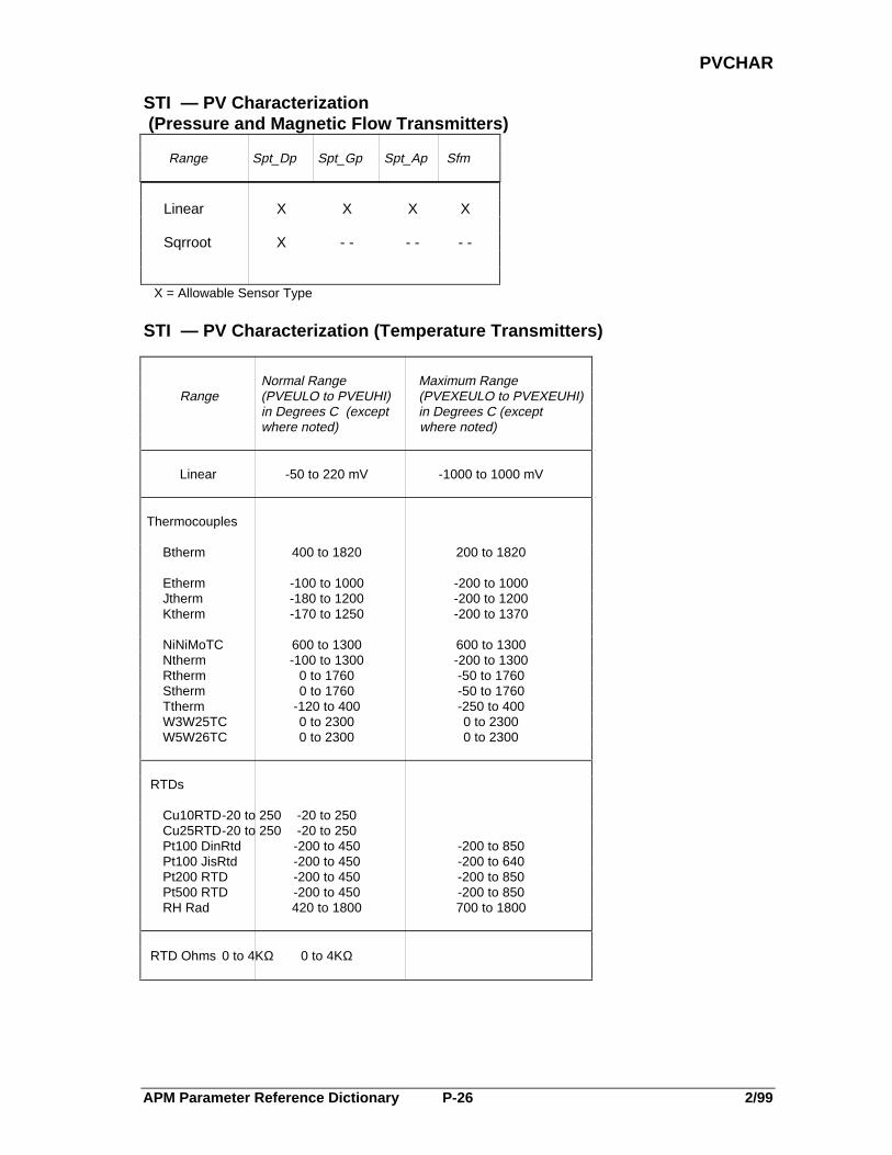
APM Parameter Reference Dictionary P-26 2/99
PVCHAR
STI — PV Characterization (Pressure and Magnetic Flow Transmitters)
Range Spt_Dp Spt_Gp Spt_Ap Sfm
Linear X X X X
Sqrroot X - - - - - -
X = Allowable Sensor Type
STI — PV Characterization (Temperature Transmitters)
Normal Range Maximum Range Range (PVEULO to PVEUHI) (PVEXEULO to PVEXEUHI)
in Degrees C (except in Degrees C (except where noted) where noted)
Linear -50 to 220 mV -1000 to 1000 mV
Thermocouples
Btherm 400 to 1820 200 to 1820
Etherm -100 to 1000 -200 to 1000Jtherm -180 to 1200 -200 to 1200Ktherm -170 to 1250 -200 to 1370
NiNiMoTC 600 to 1300 600 to 1300Ntherm -100 to 1300 -200 to 1300Rtherm 0 to 1760 -50 to 1760Stherm 0 to 1760 -50 to 1760Ttherm -120 to 400 -250 to 400W3W25TC 0 to 2300 0 to 2300W5W26TC 0 to 2300 0 to 2300
RTDs
Cu10RTD-20 to 250 -20 to 250Cu25RTD-20 to 250 -20 to 250Pt100 DinRtd -200 to 450 -200 to 850Pt100 JisRtd -200 to 450 -200 to 640Pt200 RTD -200 to 450 -200 to 850Pt500 RTD -200 to 450 -200 to 850RH Rad 420 to 1800 700 to 1800
RTD Ohms 0 to 4KΩ 0 to 4KΩ

APM Parameter Reference Dictionary P-27 2/99
PVCHAR
PVCHAR(FlowComp)Type: E:VALCHARLock: PtBldDefault: SqRootPtRes: APM
PV Characterization Option—Defines the display characterization to be usedfor characterizing the input PV value of Regulatory PV point configuring withFlow Compensation.
Range: 12-Linear (The COMPTERM compensation is not square rooted)13 SqRoot (The COMPTERM compensation is square rooted)
PVCHGDLYType: IntegerLock: SuprDefault: 0 secondsPtRes: APM
PV Change Delay time in Seconds—Defines the time(in seconds) that a pointwith a previously detected PV change event is guaranteed to remain at the newvalue even if the PV returns to its original value. If the point remains at itsnew value when the delay timer expires, the point is held at the new value.
Range: 0 to 60 seconds
Helpful Hint: PVCHGDLY requires that EVTOPT = EIP, SOE, or EIPSOE.
PVCLAMPType: E:PVCLAMPLock: Eng/PBDefault: NoClampPtRes: APM
PV Clamping Option—Defines whether PV clamping is to be used for thisdata point. If PVCLAMP = Clamp and the PV extended range is exceeded, PVvalue status PVSTS is marked Uncertain and the PV is set equal to theextended limit that was violated.
Range: 0-NoClamp (No clamping of the PV value)1-Clamp (Clamp PV value at range extension limit)
PVEQN (FlowComp)Type: E:ALGOEQNLock: PtBldDefault: EqAPtRes: APM
PV Equation Type—Defines the equation type (EqA-EqE) to be used for thisPV algorithm. Refer to the APM Control Functions and Algorithms manualfor more information.
Range: Comp. Inputs Type of Compensation0-EqA G Mass/Volumetric flow of liquid1-EqB P and T Mass flow of gases and vapors2-EqC G, P, and T Mass flow of gases and vapors w/specific gravity3-EqD G, P, and T Volumetric flow of gases and vapors4-EqE P, T, X, and Q Mass flow of steam
G = measured or calculated specific gravity or molecular weight, P = measured actual gage pressure, T =measured actual temperature, X = measured actual steam compressibility and Q = measured actual steamquality.
PVEQN (HiLoAvg)
Type: E:ALGOEQNLock: Eng/PBDefault: EqAPtRes: APM
PV Equation Type—Defines the equation type (EqA-EqC) to be used for thisPV algorithm. Refer to the APM Control Functions and Algorithms manual formore information.
Range: 0-EqA (Select and identify highest of up to six inputs)1-EqB (Select and identify lowest of up to six inputs)2-EqC (Calculate the average of up to six inputs)

APM Parameter Reference Dictionary P-28 2/99
PVEQN
PVEQN (MidOf3)Type: E:ALGOEQNLock: Eng/PBDefault: EqAPtRes: APM
PV Equation Type—Defines the equation type (EqA-EqC) to be used for thisPV algorithm. Refer to the APM Control Functions and Algorithms manualfor more information.
Range: 0-EqA (Highest good input when one or two are bad)1-EqB (Lowest good input when one or two are bad)2-EqC (Average of all good inputs)
PVEQN (Summer)Type: E:ALGOEQNLock: PtBldDefault: EqAPtRes: APM
PV Equation Type—Defines the equation type (EqA or EqB) to be used forthis PV algorithm. Refer to the APM Control Functions and Algorithmsmanual for more information.
Range: 0-EqA (P1 input is scaled and biased)1-EqB (Up to six inputs are scaled and summed with an overall bias applied)
PVEQN (Totalizr)Type: E:ALGOEQNLock: Eng/PBDefault: EqAPtRes: APM
PV Equation Type—Defines the equation type (EqA-EqF) to be used for thisPV algorithm. Refer to the APM Control Functions and Algorithms manualfor more information.
Range: Option Warm Restart Action Bad Input Handling0-EqA Continue Use zero1-EqB Continue Use last good value2-EqC Continue Set Bad and stop3-EqD Set Bad, and stop Use zero4-EqE Set Bad, and stop Use last good value5-EqF Set Bad, and stop Set Bad and stop
PVEQN(VdtLdLag)Type: E:ALGOEQNLock: PtBldDefault: EqAPtRes: APM
PV Equation Type—Defines the equation type (EqA-EqD) to be used for thisPV algorithm. Refer to the APM Control Functions and Algorithms manualfor more information.
Range: 0-EqA (Lead-Lag)1-EqB (Fixed dead time)2-EqC (Variable dead time)3-EqD (Variable dead time with two lags)
Helpful Hint: For Equations C and D, the dead time is changed in steps of NLOC*NRATE*TSwhere NLOC is configurable from 2 to 30, for better resolution of dead time.

APM Parameter Reference Dictionary P-29 2/99
PVEUHI
PVEUHI (RegCtl, RegPV)Type: RealLock: EngrDefault: NaNPtRes: APM
PV High Range in Engineering Units—Note that PVEUHI cannot be writtenwith NaN. NaN is the default value only.
Range: PVEULO to PVEXEUHI, NaN
Helpful Hint: For Smartline transmitters, refer to Table A-3 in the PM/APM SmartlineTransmitter Integration Manual, PM12-410.
PVEULO (RegCtl, RegPV)Type: RealLock: EngrDefault: NaNPtRes: APM
PV Low Range in Engineering Units—Note that PVEULO cannot be writtenwith NaN. NaN is the default value only.
Range: PVEXEULO to PVEUHI, NaN
Helpful Hint: For Smartline transmitters, refer to Table A-3 in the PM/APM SmartlineTransmitter Integration Manual, PM12-410.
PVEXEUHIType: RealLock: EngrDefault: NaNPtRes: APM
PV Extended Engineering Unit Range High—Both PVEXEUHI andPVEXEULO are used to clamp or detect a bad PV value. Refer to parameterPVEXEULO. Note that PVEXEUHI cannot be written with NaN. NaN is thedefault value only.
Range: > PVEUHI, NaN
PVEXEULOType: RealLock: EngrDefault: NaNPtRes: APM
PV Extended Engineering Unit Low Range—For the LLAI IOP withThermocouple and RTD sensor types, extended PV range parameters are VIEWONLY. Their values are defaulted based on the sensor types, the thermocouplerange option, and temperature scale. The tables below show the default values indegrees C. For other engineering units, these values are appropriately converted.Note that PVEXEULO cannot be written with NaN. NaN is the default valueonly.
Range < PVEULO, NaN
Defaults for Extended Range PV Parameters When SENSRTYP = THERMCPL, PVTEMP = Degrees C TCRNGOPT = NORMAL TCRNGOPT = EXTENDED
PVCHAR PVEXEULO PVEXEUHI PVEXEULO PVEXEUHIBtherm 600 1650 100 1820Etherm -150 500 -200 1000Jtherm -100 750 -200 1200Ktherm 0 1100 -100 1370Rtherm 550 1500 0 1700RPtherm 550 1500 0 1770Stherm 550 1500 0 1700Ttherm -200 300 -230 400
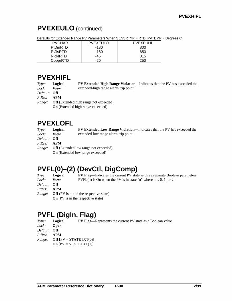
APM Parameter Reference Dictionary P-30 2/99
PVEXHIFL
PVEXEULO (continued)
Defaults for Extended Range PV Parameters When SENSRTYP = RTD, PVTEMP = Degrees CPVCHAR PVEXEULO PVEXEUHI
PtDinRTD -180 800PtJisRTD -180 650NicklRTD -45 315CopprRTD -20 250
PVEXHIFLType: LogicalLock: ViewDefault: OffPtRes: APM
PV Extended High Range Violation—Indicates that the PV has exceeded theextended-high range alarm trip point.
Range: Off (Extended high range not exceeded)On (Extended high range exceeded)
PVEXLOFLType: LogicalLock: ViewDefault: OffPtRes: APM
PV Extended Low Range Violation—Indicates that the PV has exceeded theextended-low range alarm trip point.
Range: Off (Extended low range not exceeded)On (Extended low range exceeded)
PVFL(0)–(2) (DevCtl, DigComp)Type: LogicalLock: ViewDefault: OffPtRes: APM
PV Flag—Indicates the current PV state as three separate Boolean parameters.PVFL(n) is On when the PV is in state "n" where n is 0, 1, or 2.
Range: Off (PV is not in the respective state)On (PV is in the respective state)
PVFL (DigIn, Flag)Type: LogicalLock: OperDefault: OffPtRes: APM
PV Flag—Represents the current PV state as a Boolean value.
Range: Off [PV = STATETXT(0)]On [PV = STATETXT(1)]

APM Parameter Reference Dictionary P-31 2/99
PVFORMAT
PVFORMAT (RegCtl, RegPV)Type E:VALFORMTLock: EngrDefault: D1PtRes: APM
PV Decimal Point Format—Defines the decimal format that is to be used todisplay the PV and SP values. It contains up to eight characters including theminus sign and decimal point.
Range: 0-D0 (-XXXXXX.)1-D1 (-XXXXX.X)2-D2 (-XXXX.XX)3-D3 (-XXX.XXX)
PVHHFL (RegCtl, RegPV)Type: LogicalLock: ViewDefault: OffPtRes: APM
PV High High Alarm Flag— Indicates whether the PV has exceeded the alarmtrip point established by the PVHHTP parameter.
Range: Off (High High limit not exceeded)On (High High limit exceeded)
PVHHPR (RegCtl, RegPV)Type: E:ALPRIORLock: EngrDefault: LowPtRes: NIM
PV High High Alarm Priority— Defines the priority of the PV high high alarm.
Range: JnlPrint (Alarm is historized and reported to the printer but not annunciated)Printer (Alarm is reported to the printer but not historized and not annunciated)Emergncy (Alarm is historized, annunciated, and reported to all alarm summary displays)High (Alarm is historized, reported to Area Alarm Summary Display and Unit Alarm SummaryDisplay)Low (Alarm is historized, reported to the Unit Alarm Summary Display, and annunciated)Journal (Alarm is historized but not reported to Universal Stations and not annunciated)NoAction (Alarm is not reported to the system and not annunciated)
Helpful Hint: PVHHPR configuration requires PVHHTP ≠ NaN.
PVHHTP (AnalgIn, RegPV)Type: RealLock: SuprDefault: NaNPtRes: APM
PV High High Alarm Trip Point— Defines the PV high high alarm trip pointfor this point.
Range: PVHITP to PVEXEUHI, NaN
Helpful Hint: PVHHTP configuration requires PVHITP • NaN.

APM Parameter Reference Dictionary P-32 2/99
PVHHTP
PVHHTP (RegCtl, RegPV)Type: RealLock: SuprDefault: NaNPtRes: APM
PV High High Alarm Trip Point— Defines the PV high high alarm trip pointfor this point.
Range: PVHITP to PVEUHI, NaN
Helpful Hint: PVHHTP configuration requires PVHITP• NaN.
PVHIFL (RegCtl, RegPV)Type: LogicalLock: ViewDefault: OffPtRes: APM
PV High Alarm Flag—Indicates that the PV has exceeded the alarm trip pointestablished by parameter PVHITP.
Range: Off (No PV High alarm)On (High PV alarm)
PVHIPR (RegCtl, RegPV)Type: E:ALPRIORLock: EngrDefault: LowPtRes: NIM
PV High Alarm Priority— Defines the priority of the PV high alarm for thispoint.
Range: JnlPrint (Alarm is historized and reported to the printer but not annunciated)Printer (Alarm is reported to the printer but not historized and not annunciated)Emergncy (Alarm is historized, annunciated, and reported to all alarm summary displays)High (Alarm is historized, reported to Area Alarm Summary Display and Unit Alarm SummaryDisplay)Low (Alarm is historized, reported to the Unit Alarm Summary Display, and annunciated)Journal (Alarm is historized but not reported to Universal Stations and not annunciated)NoAction (Alarm is not reported to the system and not annunciated)
Helpful Hint: PVHIPR configuration requires PVHITP • NaN.
PVHITPType: RealLock: SuprDefault: NaNPtRes: APM
PV High Alarm Trip Point— Defines the trip point for the PV high alarm forthis point.
Range: PVLOTP to PVHHTP, NaN
PVINITType: LogicalLock: ProgDefault: OffPtRes: APM
PV Initialization Request Flag—Indicates that an initialization request has beenmade for this point.
Range: Off (No 1-shot initialization)On (Initializes the PV filter and the algorithm for a 1-shot single sample time).

APM Parameter Reference Dictionary P-33 2/99
PVLLFL
PVLLFL (RegCtl, RegPV)Type: LogicalLock: ViewDefault: OffPtRes: APM
PV Low Low Alarm Flag— Indicates that the PV has exceeded the alarm trippoint established by the PVLLTP parameter.
Range: Off (PV > Low Low alarm trip point)On (PV < Low Low alarm trip point)
PVLLPR (RegCtl, RegPV)Type: E:ALPRIORLock: EngrDefault: LowPtRes: NIM
PV Low Low Alarm Priority— Determines the priority of the PV low lowalarm for this data point.
Range: JnlPrint (Alarm is historized and reported to the printer but not annunciated)Printer (Alarm is reported to the printer but not historized and not annunciated)Emergncy (Alarm is historized, annunciated, and reported to all alarm summary displays)High (Alarm is historized, reported to Area Alarm Summary Display and Unit Alarm SummaryDisplay)Low (Alarm is historized, reported to the Unit Alarm Summary Display, and annunciated)Journal (Alarm is historized but not reported to Universal Stations and not annunciated)NoAction (Alarm is not reported to the system and not annunciated)
Helpful Hint: PVLLPR configuration requires PVLLTP ≠ NaN.
PVLLTP (AnalgIn, RegPV, PI)Type: RealLock: SuprDefault: NaNPtRes: APM
PV Low Low Alarm Trip Point— Defines the trip point for the PV low lowalarm for this point.
Range: PVEXEULO to PVLOTP, NaN
Helpful Hint: PVLLTP configuration requires PVLOTP ≠ NaN.
PVLLTP (RegCtl)Type: RealLock: SuprDefault: NaNPtRes: APM
PV Low Low Alarm Trip Point— Defines the trip point for the PV low lowalarm for this point.
Range: PVEULO to PVLOTP, NaN
Helpful Hint: PVLLTP configuration requires PVLOTP ≠ NaN.
PVLOFL (RegCtl, RegPV)Type: LogicalLock: ViewDefault: OffPtRes: APM
PV Low Alarm Flag—Indicates that the PV has exceeded the alarm trip pointestablished by parameter PVLOTP.
Range: Off (PV > Low alarm trip point)On (PV < Low alarm trip point)

APM Parameter Reference Dictionary P-34 2/99
PVLOPR
PVLOPR (RegCtl, RegPV)Type: E:ALPRIORLock: EngrDefault: LowPtRes: NIM
PV Low Alarm Priority— Defines the priority of the PV low alarm for thispoint.
Range: JnlPrint (Alarm is historized and reported to the printer but not annunciated)Printer (Alarm is reported to the printer but not historized and not annunciated)Emergncy (Alarm is historized, annunciated, and reported to all alarm summary displays)High (Alarm is historized, reported to Area Alarm Summary Display and Unit Alarm SummaryDisplay)Low (Alarm is historized, reported to the Unit Alarm Summary Display, and annunciated)Journal (Alarm is historized but not reported to Universal Stations and not annunciated)NoAction (Alarm is not reported to the system and not annunciated)
Helpful Hint: PVLOPR configuration requires PVLOTP ≠ NaN.
PVLOTP (RegCtl, RegPV)Type: RealLock: SuprDefault: NaNPtRes: APM
PV Low Alarm Trip Point— Defines the trip point for the PV low alarm forthis point.
Range: PVLLTP to PVHITP,NaN
PVNORMAL (DevCtl, DigIn, DigComp)Type: E:STATETXTLock: Supr (Engr to change to/from NONE)Default: N/APtRes: APM
PV Normal State—Defines the normal state of the PV using the appropriateSTATETXT descriptor.
Range: STATETXT(0) descriptor (Defaulted to Off for PV State 0)STATETXT(1) descriptor (Defaulted to On for PV State 1)STATETXT(2) descriptor (Defaulted to State2 for PV State 2; internally set to $NULL for two- state devices; does not apply to DigIn point)NONE (No off normal checking)
Helpful Hint: PV normal state text descriptor describes the normal (desired) state,such as Run, Stop, Open, Closed.
APM Parameter Reference Dictionary P-35 2/99
PVNORMFL
PVNORMFL (DevCtl, DigIn, DigComp)Type: LogicalLock: SuprDefault: OffPtRes: APM
PV Normal State Flag—Indicates whether the normal state of the PV is active.
Range: Off (Point is in a state other than the normal state)On (Normal state is active)
Helpful Hint: PVNORMFL change requires ALMOPT = Offnorm for Digital Input points,or that PVNORMAL • None for Digital Composite or Device Control points.If set to On, causes text in STATETXT (1) to be used to describe the normalstate of the PV, otherwise text in STATETXT (0) is used.
PVP (RegCtl, RegPV)Type: RealLock: ViewDefault: NaNPtRes: APM
PV in Percent—Defines the PV as a percentage.
Range: N/A
PVRAW (AnalgIn)Type: RealLock: OperatorDefault: NaNPtRes: APM
PV Raw Value—Indicates the raw input value of the PV from the FieldTermination Assembly (FTA) before PV characterization is performed. Theunits of value for the PV are determined by the field sensor type as describedbelow.
Range: N/A
Helpful Hint: If sensor type is 0.4–2 V, 1 - 5 V, 0 - 5 V, PVRAW is in percent; if sensor type isT/C, PVRAW is in microvolts; if sensor type is in RTD, PVRAW is inmilliohms; if sensor type is slidewire, PVRAW is in ratio; if sensor type is 0–100mV, PVRAW is in millivolts.
PVRAW (DigIn)Type: LogicalLock: ViewDefault: OffPtRes: APM
Raw State of Field Contacts—Indicates the current state of the field contacts.
Range:Off Open contactsOn Closed contacts

APM Parameter Reference Dictionary P-36 2/99
PVRAW
PVRAW (PI)Type: RealLock: ViewDefault: NaNPtRes: APM
PV Raw Value—Indicates the raw input value of the PV in pulses per second.
Range: N/A
PVRAW (STI)Type: RealLock: ViewDefault: NaNPtRes: APM
PV Raw Value—Indicates the raw input value of the PV in % of span based onthe transmitter PV after PV characterization (PVCHAR) and DAMPING havebeen performed. The span of the PV is determined by using LRV as a 0%-pointand URV as a 100%-point.
Range: N/A
PVRAWHIType: RealLock: Eng/PBDefault: NaNPtRes: APM
PV Raw High Range—Defines the high end of the normal operating range forthe raw PV value (PVRAW). For a slidewire input, the units are ratio, for a0_100_MV input, the units are in millivolts.
Range: PVRAWLO to 100 for a 0_100_mv input (microvolts)PVRAWLO to 1 for a slidewire input (ratio)
PVRAWLOType: RealLock: Eng/PBDefault: NaNPtRes: APM
PV Raw Low Range—Defines the low end of the normal operating range for theraw PV value (PVRAW).
Range: 0–PVRAWHI (0 to 100 microvolts for a 0_100 mv input, or 0 to 1 ratio for a slidewire input)
PVROCNFL (RegCtl, RegPV)Type: LogicalLock: ViewDefault: OffPtRes: APM
PV Negative Rate-of-Change Alarm Flag—Indicates that the PV negative rate-of-change has exceeded the value established by the PVROCNTP parameter.
Range: Off (No PV negative rate-of-change alarm)On (PV negative rate-of-change alarm)

APM Parameter Reference Dictionary P-37 2/99
PVROCNPR
PVROCNPR (RegCtl, RegPV)Type: E:ALPRIORLock: EngrDefault: LowPtRes: NIM
PV Negative Rate-of-Change Alarm Priority—Defines the priority of the PVnegative rate-of-change alarm for this point.
Range: JnlPrint (Alarm is historized and reported to the printer but not annunciated)Printer (Alarm is reported to the printer but not historized and not annunciated)Emergncy (Alarm is historized, annunciated, and reported to all alarm summary displays)High (Alarm is historized, reported to Area Alarm Summary Display and Unit Alarm SummaryDisplay)Low (Alarm is historized, reported to the Unit Alarm Summary Display, and annunciated)Journal (Alarm is historized but not reported to Universal Stations and not annunciated)NoAction (Alarm is not reported to the system and not annunciated)
Helpful Hint: PVROCNPR configuration requires PVROCNTP • NaN.
PVROCNTP (RegCtl, RegPV)Type: RealLock: SuprDefault: NaNPtRes: APM
PV Negative Rate-of-Change Trip Point—Defines the trip point for the PVnegative rate-of-change alarm for this point. Operation is the same as forPVROCPTP except for the direction of change.
The maximum rate of change value must be less than the absolute value of:
(PVEUHI-PVEULO) * 608 .
Range: > 0.0,NaN
Helpful Hint: For RegPV points, RegCtl points, and points in a HLAI or LLAI, themaximum rate of change is one step away from PVEXEUHI to PVEXEULOin eight seconds; therefore, the maximum rate of change is(PVEXEUHI - PVEXEULO) * 7.5 units/minute. For SENSRTYP = RTD, the maximum is [800 - (-180)] * 7.5, which is 7350.
PVROCPFL (RegCtl, RegPV)Type: LogicalLock: ViewDefault: OffPtRes: APM
PV Positive Rate-of-Change Alarm Flag—Indicates that the positiverate-of-change of the PV has exceeded the value established by the PVROCPTPparameter.
Range: Off (No PV positive rate-of-change alarm)On (PV positive rate-of-change alarm)
APM Parameter Reference Dictionary P-38 2/99
PVROCPPR
PVROCPPR (RegCtl, RegPV)Type: E:ALPRIORLock: EngrDefault: LowPtRes: NIM
PV Positive Rate-of-Change Alarm Priority—Defines the priority of thepositive rate-of-change PV alarm for this point.
Range: JnlPrint (Alarm is historized and reported to the printer but not annunciated)Printer (Alarm is reported to the printer but not historized and not annunciated)Emergncy (Alarm is historized, annunciated, and reported to all alarm summary displays)High (Alarm is historized, reported to Area Alarm Summary Display and Unit Alarm SummaryDisplay)Low (Alarm is historized, reported to the Unit Alarm Summary Display, and annunciated)Journal (Alarm is historized but not reported to Universal Stations and not annunciated)NoAction (Alarm is not reported to the system and not annunciated)
Helpful Hint: PVROCPPR configuration requires PVROCPTP • NaN.
PVROCPTP (RegCtl, RegPV)Type: RealLock: SuprDefault: NaNPtRes: APM
PV Positive Rate-of-Change Trip Point—Defines the positive PV rate-of-change limit in engineering units/minute for this point; for example 25 degreesper minute. The PV value is checked every four seconds. The rate of changealarm trips if the PV rate-of-change value is exceeded for two successive scans.The alarm is reset if the PV rate-of-change falls below the rate of change valuefor two successive scans.
The maximum rate of change value must be less than the absolute value of:
(PVEUHI-PVEULO) * 608 .
Range: > 0.0,NaN
Helpful Hint: For RegPV points, RegCtl points, and points in HLAI or LLAI, the maximumrate of change is one step away from PVEXEUHI to PVEXEULO in eightseconds; therefore, the maximum rate of change is:(PVEXEUHI - PVEXEULO) * 7.5 units/minute.Example: for SENSRTYP = RTD, the maximum is: [800 - (-180)] *7.5, which = 7350.
PVSGCHTP (RegCtl, RegPV)Type: RealLock: SuprDefault: NaNPtRes: APMRange: > 0.0,
NaN
PV Significant Change Alarm Trip Point—Defines the alarm trip point for anincrement of change that occurs between configured PVHITP and PVHHTP orPVLOTP and PVLLTP alarms. For example, consider a temperature point withlimits of PVHITP = 800 degrees, PVHHTP = 850, and PVSGCHTP = 10.When the temperature rises to 800 degrees, the PVHITP alarm is annunciated,and should the temperature continue to increase, the alarm is annunciated againwhen the temperature reaches 810 degrees, 820 degrees, and so on. This allowsthe alarm to be reannunciated to remind the operator of the existence of an alarmcondition.
APM Parameter Reference Dictionary P-39 2/99
PVSOURCE
PVSOURCE (RegCtl, RegPV)Type: E:PVSOURCELock: OperDefault: AutoPtRes: APM
PV Source—Defines the source of the PV input to this data point. The PVgoes to bad when PVSOURCE is switched from Man to Sub.
Range: 0-Sub (Value is provided by a sequence program)1-Man (PV is supplied by operator or program)2-Auto (Field wiring or memory fetch supplies PV)3-Track (PV tracks OP (DigComp points only))
Helpful Hint: PVSOURCE change by an operator requires PVSRCOPT = All and DITYPE =Latched if PNTTYPE = DigIn.
PVSRCOPT (RegCtl, RegPV)Type: E:PVSRCOPTLock: Eng/PBDefault: OnlyAutoPtRes: APM
PV Source Option—Defines the PV source options available in this datapoint.
Range: 0-OnlyAuto (PV source selection is not available and field wiring or memory fetch supplies PV)1-All (PV is provided by an operator, by a sequence program, or by field wiring)
Helpful Hint: PVSRCOPT change by an operator requires DITYPE = Latched ifPNTTYPE= DigIn.
PVSTATES(0)–(4) (DevCtl, DigComp)Type: String_8Lock: ViewDefault: N/APtRes: NIMRange: N/A
PV State Descriptors—The PV state descriptors contain the text that describesthe five (0-4) possible states of a DigComp or DevCtl PV. The descriptors areset equal to whatever is configured in BADPVTXT and MOVPVTXT duringAPM Box configuration and in STATETXT(0), STATETXT(1), andSTATETXT(2) during point configuration (if PVTXTOPT = ON).
Helpful Hint: PVSTATES, if accessed by Control Language programs, obey thefollowing rules:
a. PVSTATES (0) = STATETXT (0)b. PVSTATES (1) = STATETXT (1)c. PVSTATES (2) = BADPVTXTd. PVSTATES (3) = MOVPVTXTe. PVSTATES (4) = STATETXT (2); does not apply unless
NOSTATES = 3
PVSTS (RegCtl, RegPV)Type: E:PVVALSTLock: ViewDefault: BadPtRes: APM
Status Of PV Input Value—Defines the current status of the PV value.
Range: 0-Bad (Value is bad and replaced with NaN. For an STI point, value can be set to Bad based ontransmitter gross status.)1-Uncertn (Status of the value is uncertain)2-Normal (Value is good)
APM Parameter Reference Dictionary P-40 2/99
PVTEMP
PVTEMPType: E:TEMPTURELock: PtBldDefault: Degrees CPtRes: APM
PV Temperature Scale—Defines the temperature scale to be used incharacterizing the PV input.
Range: 0-Degrees C (Celsius)1-Degrees F (Fahrenheit)2-Degrees R (Rankin)3-Degrees K (Kelvin)
Helpful Hint: PVTEMP is to be configured when PVCHAR = TC or RTD.
PVTRACK (Pid)Type: E:TRACKINGLock: Eng/PBDefault: NoTrackPtRes: APM
PV Tracking Option—Defines whether SP is to be set equal to PV.
Range: 0-NoTrack (SP is never set equal to PV)1-Track (Man mode or initialization causes SP to track PV)
Helpful Hint: SP is set equal to PV if PVTRACK = Track and the point is:a. in manual modeb. being initialized from a secondaryc. undergoing 1-shot initialization during the first sample time after
becoming active.
PVTVType: RealLock: OperDefault: NaNPtRes: APM
PV Target Value in Engineering Units—Defines the target value of the PV inengineering units.
Range: PVEXEULO to PVEXEUHI,NaN
PVTVPType: RealLock: ViewDefault: NaNPtRes: APM
PV Target Value in Percent—Indicates the target value of the PV in percent.
Range: > 0.0%, NaN
PVTXTOPT (DevCtl, DigComp)Type: LogicalLock: PtBldDefault: OffPtRes: NIM
PV Text Option—Indicates whether the BADPVTXT and MOVPVTXTparameters are configured for this point, or if the default from the box data pointshould be used.
Range: Off (The parameters are not configured for this point)On (The parameters are configured for this point)

APM Parameter Reference Dictionary Q-1 2/99
Q
-Q-
QType: RealLock: ViewDefault: 1.0PtRes: APM
Steam Quality Factor Input—Indicates the measured actual steam quality factor.
Range: > 0.0, NaN
QSTS (FlowComp)Type: E:PVVALSTLock: ViewDefault: NormalPtRes: APM
Q Input Value Status—Indicates the status of the steam quality-factor input.
Range: 0-Bad (Value is bad and replaced by NaN)1-Uncertn (Status of the value is uncertain)2-Normal (Value is good)

APM Parameter Reference Dictionary Q-2 2/99

APM Parameter Reference Dictionary R-1 2/99
R1
-R-
R1(1)–(24), R2(1)–(24) (Logic)Type: E:$PMMLGPMLock: PtBldDefault: L1PtRes: APM
Real Inputs 1 & 2—Defines the sources that provide the input values for theR1 and R2 inputs of certain logic blocks.
Range: 32..47-L1...L12 (Values from Input Connections)
48..51-NN1...NN8 (Local Numerics)
Helpful Hint: R1 configuration requires LOCALGID = EQ, NE, GT, GE, LT, LE, orCHECKBAD.
RAISDSTNType: Universal
Ent.PrmLock: PtBldDefault: NullPtRes: APM
Raise Output Pulse Destination—Defines the destination of the Raise outputpulse. RAISDSTN must point to parameters ONPULSE or OFFPULSE of aDigOut data point.
Range: ONPULSEOFFPULSE
RAISETIMType: RealLock: ViewDefault: N/APtRes: APM
Raise Output Pulse Time—Indicates the Raise output pulse time in seconds. Itis clamped to MAXPULSE or CYCLETIM, whichever is lower. If the value ofRAISETIM is smaller than MINPULSE, no pulse is issued.
Range: N/A,NaN
RAISRATEType: RealLock: SuprDefault: 100.0% per sec.PtRes: APM
Raise OP Stroke Rate in Percent/Second
Range: > 0.0% per second
APM Parameter Reference Dictionary R-2 2/99
RAMPTIME
RAMPTIMEType: RealLock: OperDefault: 0.0PtRes: APM
Ramp Time in Minutes
Range: > 0.0
Helpful Hint: RAMPTIME change by an operator requires SPOPT = Tv. The minimum valueis clamped to TS, the point sample time in minutes, while the maximum valueis clamped to 32767*TS. To change the RAMPTIME from a logic pointrequires Node=Auto and Mode Attribute=Program.
RARWSTS (RegCtl)Type: E:WINDUPLock: ViewDefault: NormalPtRes: APM
Remote Anti-Reset Windup Status
Range: 0-Normal (Free to move in either direction)1-Hi (Free to move lower)2-Lo (Free to move higher)3-HiLo (Not free to move in any direction)
Helpful Hint: RARWSTS applies only if RCASOPT = Spc, Ddc, or DdcRsp.
RATE1 (RatioCtl)Type: RealLock: SuprDefault: NaNPtRes: APM
Internal Bias Ramps Down Rate—Rate in EUs per minute at which the internalbias (BI) ramps down from the initialization value to the last value entered bythe operator. If BIAS = NaN, initialization for the primary is determinedthrough back calculation. If zero is entered, the ramp down of BI is disabled.
Range: > 0.0, NaN
RATE1 (AutoMan)Type: RealLock: SuprDefault: 0.0PtRes: APM
Rate at Which Bias Ramps Down—Rate at which the bias (B) ramps down fromthe initialization value to the last value entered by the operator. If zero isentered, the ramp down of B is disabled. If set to NaN, the internal bias BI willinstantaneously change to 0 and cause a bump in the output.
Range: > 0.0, NaN
RATE1–12 (RampSoak)Type: RealLock: SuprDefault: NaNPtRes: APM
Ramp Rate for Ramp Soak Segments 1–12
Range: Negative values are accepted to allow ramping down.

APM Parameter Reference Dictionary R-3 2/99
RATIO
RATIO (Pid)Type: RealLock: OperDefault: 1.0PtRes: APM
Ratio—Defines the ratio value by which the SP is multiplied.
Range: RTLOLM to RTHILM
RBOPT (Pid)Type: E:RBOPTLock: Eng/PBDefault: NoRatBiPtRes: APM
Ratio/Bias Option—Defines the type of ratio/bias option to be used for thisalgorithm. Refer to the APM Control Functions and Algorithms manual for adetailed description of bias and ratio options.
Range: 0-NoRatBi (No ratio/bias is used to calculate the SP)1-FixRatBi (Fixed ratio (R) and fixed bias (B) are used)2-AutoRat (R is back-calculated during initialization)3-AutoBi (B is back-calculated during initialization)
Helpful Hint: RBOPT applies to only PID-type RegCtl algorithms.
RCASOPT (AnalgOut)Type: E:$RCASOPTLock: Eng/PBDefault: NonePtRes: APM
Remote Cascade Option—Defines whether the AM is to provide the outputvalue for this data point. This option is available only when the point hasbeen configured as a Full point.
Range: 0-None (No cascade mode of any type is allowed)2-Ddc (Direct Digital Control; in cascade mode, AM point controls this point’s OP)
RCASOPT (AutoMan, IncrSum, ORSel,Switch)Type: E:$RCASOPTLock: Eng/PBDefault: NonePtRes: APM
Remote Cascade Option—Defines the type of remote cascade mode to be used.Refer to the APM Control Functions and Algorithms manual for a detaileddescription.
Range: 0-None (Only local cascade mode is allowed)2-Ddc (In cascade mode, AM point provides the output OP for this data point)

APM Parameter Reference Dictionary R-4 2/99
RCASOPT
RCASOPT (Pid)Type: E:$RCASOPTLock: Eng/PBDefault: NonePtRes: APM
Remote Cascade Option—Defines the type of remote cascade mode to be used.Refer to the APM Control Functions and Algorithms manual for a detaileddescription.
Range: 0-None (Local cascade is the only valid cascade)1-Spc (AM writes to SP within SP limits)2-Ddc (AM writes to OP. No OP limits)3-Rsp (AM writes to SP when this point is in Auto and is being initialized by its secondary. SP
limits are applied)4-DdcRsp (AM does Ddc and Rsp functions)
Helpful Hint: MODE for a point cannot be changed to Cascade by the operator or program ifa.parameter RCASOPT is configured to Ddc, Spc, or DdcRspb.the AM strategy has not yet stored to MODE, SP, or OP.Even if PVTRACK = Track, PV tracking is not performed in auto mode withINITMAN = On if RCASOPT = Rsp.
RCASOPT (RegCtl)Type: E:$RCASOPTLock: Eng/PBDefault: NonePtRes: APM
Remote Cascade Option—Defines the type of remote cascade mode to be used.Refer to the APM Control Functions and Algorithms manual for a detaileddescription.
Range: 0-None (Only local cascade mode is allowed)1-Spc (In cascade mode, AM point provides the SP for this point)2-DDC (In cascade mode, AM point provides the OP for this point)3-Rsp (In Auto mode with INITMAN = ON, the AM point provides the SP for this point)4-DDCRsp (In cascade mode, AM point provides the OP for this point)
RCASSHED (RegCtl)Type: LogicalLock: ViewDefault: OffPtRes: APM
Remote Cascade Shed—Indicates whether the mode has shed from the Cas modeto the preconfigured backup mode.
Range: Off (No mode shed)On (Mode has shed to the preconfigured backup mode)
Helpful Hint: RCASSHED applies only if RCASOPT = Spc, Ddc, or DdcRsp.
RDNHWREVType: String_2Lock: ViewDefault:PtRes: APM
APMM Control Daugher Card Revision
Range: Hexadecimal Characters 00 to FF

APM Parameter Reference Dictionary R-5 2/99
REDTAG
REDTAG (RegCtl)Type: E:REDTAGLock: Sup/EngDefault: OffPtRes: APM
Red Tag State—Allows the user to set the point as being "out of service,"indicating that this point or the associated control loop needs repair or is beingrepaired. Once this point is put in the red tag condition, the output OP is frozenat the last value or state.
Range: 0-Off (Data point is in service. Point’s OP is not frozen)1-On (Data point is out of service = point’s OP is frozen)
Helpful Hint: REDTAG change requires MODE = Man and MODATTR = Oper. Once apoint is red tagged, parameters MODE, MODATTR, and OP (output) cannotbe changed. In addition, for a RegCtl point, ESWENBST cannot be changed.
REMSOAKT (RampSoak)Type: RealLock: OperDefault: 0.0PtRes: APM
Remaining Soak Time—Indicates the amount of time remaining in the currentsoak segment.
Range: 0.0 to 120.0 minutes
RESETFL (DevCtl, DigComp)Type: LogicalLock: OperDefault: OffPtRes: APM
Reset Maintenance Statistics Flag—Used to reset maintenance statistics.
Range: OffOn (Storing to this parameter resets maintenance statistics)
Helpful Hint: This parameter can be reset by the operator only while it is red tagged. Aprogram may reset at anytime.
RESETFL (DigIn)Type: LogicalLock: ProgDefault: OffPtRes: APM
Reset Flag—Resets the accumulator to zero when the command flag transitionsfrom the Off to the On state.
Range: Off (No Reset command)On (Reset command is issued to the accumulator)
Helpful Hint: RESETFL change requires DITYPE = Accum
RESETFL(Totalizr)Type: LogicalLock: ProgDefault: OffPtRes: APM
Reset Totalizer Command Flag—Resets the total RESETVAL when this flagchanges from Off to On.
Range: OffOn

APM Parameter Reference Dictionary R-6 2/99
RESETVAL
RESETVAL (DigIn)Type: IntegerLock: OperDefault: 0PtRes: APM
Accumulator Reset Value—Value that is preset in the accumulator. Value canthen be incremented or decremented depending on the COUNTDWN parameter.
Range: 0–32767
RESETVAL (Totalizr)Type: RealLock: OperDefault: 0.0PtRes: APM
Reset Value—Value used for presetting the value to be totaled.
Range: N/A
RESTART (ProcMod)Type: E:RESTARTLock: ViewDefault: NonePtRes: APM
Process Module Restart State—Indicates the type of restart last performed bythe process module. This value will be set to a value other than “None” untilthe first preemption point.
Helpful Hint: RESTART can be used to determine if the startup was caused by failover.Following failover, RESTART takes on the value “Failover.” This value remains until the first preemption point after which it returns to “None.”
Range: 0-None (Has not been restarted)1-Failover (Running for the first time after a failover)3-Warm (Running for the first cycle after a warm start)4-Cold (Running for the first cycle after a cold start, or a power up to Run)5-PTACTVN (Running for the first cycle following the transition from Off state to Run state)
RFB(PidErfb)Type: RealLock: ViewDefault: N/APtRes: APM
Reset Feedback Input in Percent—Indicates the PV value of another data pointthat is receiving its setpoint from this data point.
Range: > 0.0
APM Parameter Reference Dictionary R-7 2/99
RG
RG (FlowComp)Type: RealLock: SuprDefault: 1.0(molecular
weight)PtRes: APM
Reference Specific Gravity—Defines the reference specific gravity or referencemolecular weight, in the same engineering units as G (measured or calculatedspecific gravity or molecular weight).
Range: N/A
RINITREQ (RegCtl)Type: LogicalLock: ViewDefault: On for
AnalgOut,Off forRegCtl
PtRes: APM
Remote Initialization Request—Indicates whether an initialization request hasbeen made.
Range: Off (No request)On (Request has been made)
Helpful Hint: RINITREQ does not apply if RCASOPT = None.
RINITVAL (RegCtl)Type: RealLock: ViewDefault: NaNPtRes: APM
Remote Initialization Value
Range: N/A,NaN
Helpful Hint: RINITVAL does not apply if RCASOPT = None.
RJRAW(1)–(168)Type: RealLock: ViewDefault: NaNPtRes: APM
Reference Junction’s Raw Count in µVolts
Range: N/A

APM Parameter Reference Dictionary R-8 2/99
RJTEMP
RJTEMP (LLAI)Type: RealLock: ViewDefault: NaNPtRes: APM
Reference Junction Temperature—Displays the current temperatures (°C) of thereference junction sensor. This value is updated only if the thermocouple inputis configured.
Range: N/A
RP (FlowComp)Type: RealLock: SuprDefault: 1.0PtRes: APM
Reference Pressure—RP is the reference pressure input and it is in the sameEngineering Unit as the P (measured or actual gage pressure) input.
Range: N/A
RPType: RealLock: SuprDefault: 1.0PtRes: APM
Minimum Pulse Time Ratio
Range: 0.01 to 100.0
RQ (FlowComp)Type: RealLock: SuprDefault: 1.0PtRes: APM
Reference Steam Quality Factor—Defines the reference steam quality factorwhich is in the same units as the Q (measured actual steam quality) input.
Range: N/A
RSPBGP$$ (RampSoak)Type: RealLock: ViewDefault: N/APtRes: APM
Ramp/Soak Percent Bar Graph Parameter—If in a ramp sequence, the value ofthe next soak percent is displayed. If in a soak sequence, the value of parameterREMSOAKT as a percent of total soak time is displayed.
Range: > 0.0
APM Parameter Reference Dictionary R-9 2/99
RSTROPT
RSTROPT (ProcMod)Type: E:$RSTROPTLock: EngDefault: OffPtRes: APM
Restart Option—Defines how the sequence program is to be started followingan Idle to Run, or power up to Run transition or a warm restart.
Range: 0-Off (Sequence is waiting for the operator command to start)1-Restart (Sequence is to be restarted from the beginning)
RT (FlowComp)Type: RealLock: SuprDefault: 1.0PtRes: APM
Reference Temperature—RT is the reference temperature input and is in the sameEngineering Unit as the T (measured actual temperature) input.
Range: N/A
RTType: RealLock: SuprDefault: 1.0PtRes: APM
Deadtime Ratio
Range: 0.01 to 100.0
RTHILM(Pid)Type: RealLock: SuprDefault: 100.0PtRes: APM
Ratio High Limit
Range: RTLOLM to 100.0,NaN
Helpful Hint: Entering NaN forces RTHILM to its extreme value (100.0%).
APM Parameter Reference Dictionary R-10 2/99
RTLOLM
RTLOLM(Pid)Type: RealLock: SuprDefault: 0.01PtRes: APM
Ratio Low Limit
Range: 0.01 to RTHILM,NaN
Helpful Hint: Entering NaN forces RTLOLM to its extreme value (0.01).
RUNSTATE (ProcMod)Type: LogicalLock: ViewDefault: OffPtRes: APM
Run State—Indicates that the point is in the RUN sequence execution state.
Range: Off (Process Module point is not in the RUN state)On (Process Module point is in the RUN state)
RV (Timer)Type: IntegerLock: ViewDefault: 0PtRes: APM
Remaining Time—Indicates the amount of time remaining (in seconds orminutes) that the timer is to run.
Range: >0
Helpful Hint: RV represents remaining time computed as SP - PV. If SP = 0, RVis always 0.
RX (FlowComp)Type: RealLock: SuprDefault: 1.0PtRes: APM
Reference Steam Compressibility—Defines the reference steam compressibility,and is in the same engineering units as the X (measured actual steamcompressibility).
Range: Anything except NaN
APM Parameter Reference Dictionary S-1 2/99
S0BOXCLR
-S-
S0BOXCLR, S1BOXCLR, S2BOXCLRType: E:BOXCOLORLock: ViewDefault: N/APtRes: NIM
State Box Color—Used only for US displays; corresponds to the box colorsconfigured using S0BOXCLR - BOXCLR(0), S1BOXCLR – BOXCLR(1),S2BOXCLR - BOXCLR(2).
Range: RedGreenWhiteBlackCyanYellowBlueMagenta
S1 (PidErfb)Type: LogicalLock: ProgDefault: OffPtRes: APM
Tracking Switch—Determines whether the CV value of this data point isreplaced by the tracking value.
Range: Off (CV value is not replaced)On (CV value is replaced by the tracking value)
S1 (STI)
Type: String_127Lock: ViewDefault: BlankPtRes: APMRange: N/A, Blank
Transmitter Status—Indicates the current status of the smart transmitterassociated with this STI point. Transmitter status consists of - Transmitter scratch pads 1, 2, 3 & 4 - Detailed transmitter status - List of parameters whose values are not the same in both the STI IOP databaseand the transmitter’s database. (Parameters are mismatched.)
S1, S2 (RampSoak)Type: LogicalLock: ViewDefault: OffPtRes: APM
Mark 1 and Mark 2 Flags—These flags are used to indicate to other data pointsthat a specified time has elapsed from the beginning of a specified ramp or soaksegment. Refer to the APM Control Functions and Algorithms manual fordetailed information.
Range: OffOn
APM Parameter Reference Dictionary S-2 2/99
S1–S4
S1(1)–(24) through S4(1)–(24) (Logic)Type: E:$PMMLGPMLock: PtBldDefault: L1PtRes: APM
Status Inputs 1-4—Defines the input source for each of the S1-S4 inputs tothe logic block.
Range: FL1...FL12 (Input source is a local flag; they can be either On or Off)SO1...SO24 (Input source is the status output (SOn) from another logic block.)L1...L12 (Input source is the configured input connection; they can be either On or Off)
S1–S4 (Switch)Type: LogicalLock: OperDefault: OnPtRes: APM
Select X1-X4 Request Flag—Indicate whether the respective input (X1-X4) hasbeen selected as the input to this algorithm.
Range: OffOn (Respective input has been selected)
S1BGNTIM, S2BGNTIM (RampSoak)Type: RealLock: SuprDefault: 0.0PtRes: APM
Mark 1 and Mark 2 Begin Times—Times at which Mark Function Flag S1 orS2 is turned on. Refer to the APM Control Functions and Algorithms manualfor detailed information.
Range: > 0.0 to 120 minutes
S1ENDTIM, S2ENDTIM (RampSoak)Type: RealLock: SuprDefault: 0.0PtRes: APM
Mark 1 and Mark 2 End Time—Times at which Mark Function Flags S1 and S2are turned Off. Refer to the APM Control Functions and Algorithms manual fordetailed information.
Range: > 0.0 to 120 minutes
S1REV(1)–(24) through S3REV(1)–(24) (Logic)Type: LogicalLock: PtBldDefault: OffPtRes: APM
S1, S2, S3 Inputs Reversed—Allows the user to selectively reverse (invert) anyof the inputs to a logic block.
Range: Off (Input is direct)On (Input is reversed)
Helpful Hint: Reversed (inverted) inputs apply only to LOGALGID = And, Or, Nand, and Nor.

APM Parameter Reference Dictionary S-3 2/99
S1SEGID, S2SEGID
S1SEGID, S2SEGID (RampSoak)Type: E:CURSEGIDLock: SuprDefault: Ramp1PtRes: APM
Mark 1 and Mark 2 Segment Identifiers—Refer to the APM ControlFunctions and Algorithms manual for detailed information.
Range: 0-Ramp1 1-Soak12-Ramp2 3-Soak2 : and :
20-Ramp11 21-Soak1122-Ramp12 23-Soak12
SAFEOPType: RealLock: EngrDefault: N/APtRes: APM
Safe Operation For Safety Shutdown—Defines the safe output value (OP) for apoint when the SHUTDOWN parameter is set to On.
Range: -6.9 to 106.9%,NaN
SAFOPCMD (PosProp, PIDPosPr)Type: E:$SFOPCMDLock: EngrDefault: IdlePtRes: APM
Safe OP Command—Defines the Safe OP state for position proportional andPID position proportional.
Range: 0-IDLE (Output does not change)1-RAISE (Output is raised)2-LOWER (Output is lowered)
SCANPER (APM Box)Type: RealLock: PtBldDefault: 1.0PtRes: APM
SI Data Scan Period—Defines the period that the APMM Control Processorscans serial interface data that is mapped to the Array point.
Range: .25 seconds.5 seconds1.0 seconds
SCANPRI (Array)Type: E:$SCANPRILock: PtBldDefault: LowPtRes: APM
SI Data FTA Scan Priority—Indicates which scan priority the serial interfaceFTA is using when reading data from the serial link.
Range: Low (Scan at low priority)High (Scan at high priority)
APM Parameter Reference Dictionary S-4 2/99
SCANRATE
SCANRATE (APM Box)Type: E:$PMMSNRTLock: PtBldDefault: Reg1Log1PtRes: APM
Scan Rate—Defines the number of times that all slots of a particular type arescanned and processed. Refer to the APM Control Functions and Algorithmsmanual for information on how to determine the processing capacity of the APM.
Range: RegCtl & RegPV Logic, DigComp & DevCtl ProcMod Scan Freq Scan Freq Scan Freq
0-Null - - - - - - - - - - - -1-Reg1Log1 1 second 1 second 1 second2-Reg1Log2 1 second 1/2 second 1 second3-Reg1Log4 1 second 1/4 second 1 second5-Reg2Log2 1/2 second 1/2 second 1 second6-Reg2Log4 1/2 second 1/4 second 1 second8-Reg4Log4 1/4 second 1/4 second 1 second
CAUTION If you attempt to load a new SCANRATE or a new point mix from the DEB, the following items should be noted:
a. If the new SCANRATE and point mix are accepted by the APMM and if they differ in any way fromtheir previous values, then the point database will be set to the default state and must bereloaded from the IDF.
b. If the SCANRATE or any part of the point mix is rejected by the APMM, then the APMM databaseremains unchanged; the SCANRATE and the point mix also remain unchanged.
c. If the SCANRATE and the point mix are equivalent to the previous values, then the APMMdatabase remains unchanged.
SEALOPT (DevCtl, DigComp)Type: E:$SEALOPTLock: Eng/PBDefault: NonePtRes: APM
Seal-in Circuit Option—Configures the seal-in circuit option.
Range: 0-None (Sealin is not configured)1-Sealin (Sealin is configured)
SECOND (APM Box)Type: IntegerLock: ViewDefault: N/APtRes: APM
Current Second
Range: 0 to 59
SECSYNCType: E:$SECSYNCLock: ViewDefault:PtRes: APM
Secondary Synchronization Status
Range: Synched (Modules are synchronized)NoSynch (Modules are out of synchronization)

APM Parameter Reference Dictionary S-5 2/99
SECVAR
SECVAR (DevCtl)Type: RealLock: ViewDefault: 0.0PtRes: APM
Secondary Variable—The analog feedback, normally the motor current or flow.
Range: Real Numbers including NaN
SECVAR (STI)
Type: RealLock: ViewDefault: NaNPtRes: APM
Secondary Variable—Displays the value of the secondary variable of the smarttransmitter as follows: Pressure transmitter—temperature of the transmitter Temperature transmitter—cold junction temperature Flow transmitter—totalized value.
Range: N/A, NaN
SEGTOT (GenLin)Type: IntegerLock: SuprDefault: 1PtRes: APM
Total Number of Segments—Defines the total number of segments in the curve.
Range: 1 to 12
SEGTYPE (RampSoak)Type: E:SEGTYPELock: ViewDefault: N/APtRes: APM
Segment Type—Indicates the current segment being executed by the RegCtlpoint.
Range: 0-Ramp (Ramp segment)1-Soak (Soak segment)
SELINP (HiLoAvg, MidOf3)Type: E:PINPLock: ViewDefault: SelectP1PtRes: APM
Selected Input—Indicates the selected input for the algorithm.
Range: 1-SelectP1 (HiLoAvg and MidOf3 algorithms)2-SelectP2 (HiLoAvg and MidOf3 algorithms)3-SelectP3 (HiLoAvg and MidOf3 algorithms)4-SelectP4 (Only HiLoAvg algorithm)5-SelectP5 (Only HiLoAvg algorithm)6-SelectP6 (Only HiLoAvg algorithm)

APM Parameter Reference Dictionary S-6 2/99
SELXINP
SELXINP (ORSel, Switch)Type: E:XINPLock: View (for ORSel) Oper (for Switch)Default: SelectX1PtRes: APM
Selected X Input—For the ORSel algorithm, this parameter indicates theinputs to the algorithm that have not been bypassed by the BYPASS1-BYPASS4 parameters. For the Switch algorithm, this parameter allows theoperator to specify the input (X1-X4) to the algorithm. Refer to the APMControl Functions and Algorithms manual for a detailed description.
Range: 1-SelectX12-SelectX23-SelectX34-SelectX4
SENSRTYP (HLAI &LLAI)
Type: E:$SENSRTYLock: PtBldDefault: 1_5_VPtRes: APM
Sensor Type—Defines the type of field sensor connected to the FieldTermination Assembly (FTA). 0_100_mV, Thermocouple, and RTD sensortypes do not apply for HLAI. P4_2_V and slidewire sensor types do not applyfor LLAI. Refer to PVCHAR for more information.
Range: 0-1_5_V (1 to 5 volts)1-0_5_V (0 to 5 volts)2-0_100_mV (0 to 100 millivolts)3-Thermcpl (Thermocouple)4-RTD (Resistance Temperature Device)5-P4_2_V (0.4 to 2 volts)6-Slidwire (Slidewire Resistance Device)
SENSRTYP (LLMUX, RHMUX)
Type: E:$SENSRTYLock: PtBldDefault: 0 - 100 mVPtRes: APM
Sensor Type—Defines the type of field sensor connected to the FieldTermination Assembly (FTA). Refer to PVCHAR for more information.
Range: 2-0_100_mV (0 to 100 millivolts)3-Thermcpl (Thermocouple)4-RTD (Resistance Temperature Device) NOTE: RTD is not supported by RHMUX IOP.
SENSRTYP (STI)
Type: E:$SENSRTYLock: PtBldDefault: Spt_DpPtRes: APM
Sensor Type—Defines the Smart Transmitter type. Refer to PVCHAR formore information. Note that SENSRTYP must match the FTA. The pointstatus is set to SOFTFAIL if a mismatch occurs.
Range: 8-SPT_DP (ST3000—differential pressure)9-SPT_GP (ST3000—gauge pressure)10-SPT_AP (ST3000—absolute pressure)11-STT (STT3000—temperature)12-SFM (MagneW 3000—magnetic flow and most Multivariable transmitters)
Helpful Hint: For multivariable transmitters, refer to the transmitter manual for the defaultvalue of the specific device.
APM Parameter Reference Dictionary S-7 2/99
SEQERR
SEQERR (ProcMod)Type: IntegerLock: ViewDefault: 0PtRes: APM
Sequence Error—Indicates that a sequence error or failure was detected. A code isdisplayed to indicate the nature of the error or failure. When an error is detected,the sequence execution state is changed to ERROR; when a failure is detected,the execution state is changed to FAIL.
Range: 0 (No error)1-100 (Not used)
Error Codes101 (Not used)102 (Array index error)103 (Illegal IMD code)104 (Illegal variable/operator code)105 (Interpreter stack overflow)106 (GOTO destination error)107 (Key level error)108 (Configuration mismatch error)109 (I/O Link prefetch overflow)110 (Subroutine nesting level error)111 (Illegal value error)112 (Fail statement)113 (IOL-Prefetch buffer full)114 (IOL-Poststore buffer full)115 (UCN-Prefetch buffer full)116 ((UCN-Postore buffer full)117-164 (Not used)
Failure Codes165 (Sequence has been halted by the operator)166 (Sequence jumped to an abnormal condition handler which was not enabled)167 (Not used)168 (Timeout condition occurred on WAIT statement)169 (An attempt was made to start a sequence that has not been loaded)170 (Communication error in READ/WRITE statement)171 (Communication error detected during I/O Link access. This error is also generated for all post-store problems)172 (Range Error)173 (An attempt was made to write to a point that was not in the proper mode)174 (Interlock error)175-255 (Not used)
SEQEXEC (ProcMod)Type: E:SEQEXECLock: ViewDefault: NLPtRes: APM
Sequence Execution State—Indicates the current execution state of thesequence program that is executing in the process module. Refer to the APMControl Functions and Algorithms manual for a detailed description of theexecution states.
Range: 0-NL (Not Loaded)1-DLL (Down-line loading is in progress)2-Loaded (Sequence has been loaded into the process module)3-End (Sequence has stopped because it has run to completion)4-Pause (Sequence has stopped because of a PAUSE statement, or after each step is executed
while in the SnglStep sequence execution mode.)5-Fail (Sequence has stopped because a sequence failure was detected)6-Error (Sequence has stopped because a sequence error was detected)7-Run (Sequence is running in the process module)

APM Parameter Reference Dictionary S-8 2/99
SEQMODE
SEQMODE (ProcMod)Type: E:SEQMODELock: Determined by CNTLLOCK parameterDefault: AutoPtRes: APM
Sequence Execution Mode—Defines the manner in which the sequence isexecuted.
Range: 0-Auto (Normal mode of sequence operation. Sequence runs from beginning to end withoutoperator intervention.)
1-SemiAuto (Sequence stops at all PAUSE statements in the sequence. Operator action isrequired to restart the sequence.)
2-SnglStep (Sequence is executed one step at a time, and operator action is required to resumeexecution. This mode is normally used for debugging.)
SEQNAME (ProcMod)Type: String_8Lock: ViewDefault: BlankPtRes: APM
Sequence Name—Defines the name of the CL sequence that currently resides inthe process module.
Range: N/A
SEQOBJSZ (ProcMod)Type: IntegerLock: ViewDefault: 0PtRes: APM
Sequence Program Size—Indicates the number of memory blocks used by thesequence currently loaded in this process module.
Range: >0
SEQPR (ProcMod)Type: E:ALPRIORLock: EngrDefault: LowPtRes: NIM
Sequence Priority—Defines the alarm priority for Process Module points. Notethat even when the Sequence priority is Journal, the alarm indicators still appearon the Group and Detail displays.
Range: Emergncy (Alarm is historized, annunciated, and reported to all alarm summary displays)High (Alarm is historized, reported to Area Alarm Summary Display and Unit Alarm SummaryDisplay)Low (Alarm is historized, reported to the Unit Alarm Summary Display, and annunciated)JnlPrint (Alarm is historized and reported to the printer but not annunciated)Printer (Alarm is reported to the printer but not historized and not annunciated)Journal (Alarm is historized but not reported to Universal Stations and not annunciated)NoAction (Alarm is not reported to the system and not annunciated)
SEQPRGSZ (APM Box)Type: IntegerLock: ViewDefault: N/APtRes: APM
Sequence Program Size—Gives total APM memory available for sequenceprogram, in blocks.
Range: N/A

APM Parameter Reference Dictionary S-9 2/99
SEQPROC
SEQPROC (APM Box)Type: E:$SEQPROCLock: PtBldDefault: 1_PUPtRes: APM
Sequence Processing Rate—Specifies the number of processing units per ProcessModule data points that can be processed each quarter second cycle.
Range: 1_PU One PU per Process Module point is allocated per scan (40 points can be processedper scan)2_PU Two PUs per Process Module point are allocated per scan (20 points can be processedper scan)
SEQSLTSZ (ProcMod)Type: IntegerLock: PtBldDefault: 0PtRes: APM
Sequence Slot Size—Defines the size of the program memory allocated for thisprocess module in terms of blocks. Each block is 32 words long. The actualsize is limited by the available memory.
Range: >0
SERIALNO (STI)
Type: String_8Lock: ViewDefault: BlankPtRes: APM
Serial Number/PROM Number of the Smart Transmitter
Range: N/A
SGALGID(1)–(2) (DevCtl)Type: E:$GTALGID in an Array (1..2)Lock: PtBldDefault: NonePtRes: APM
Secondary Gate ID—Defines the algorithm IDs for secondary gates.
Range: NULL (No algorithm)AND (And Gate algorithm)OR (Or Gate algorithm)NAND (Nand Gate algorithm)NOR (Nor Gate algorithm)XOR (Exclusive Or Gate algorithm)PAND (Pulse Nand Gate algorithm)POR (Pulse or Gate algorithm)PNAND (Pulse Nand Gate algorithm)PNOR (Pulse Nor Gate algorithm)PXOR (Pulse Exclusive or Gate algorithm)

APM Parameter Reference Dictionary S-10 2/99
SGDSTN
SGDSTN(1)–(2) (DevCtl)Type: E:$GATDSTN in an Array (1..2)Lock: PtBldDefault: NonePtRes: APM
Secondary Gate Destination—Defines the output destination for the secondarygates.
Range: None (No destination)SI0 (Output goes to Safety Interlock)I0, I1, I2 (Output goes to Interlocks)P0, P1, P2 (Output goes to Permissives)SOCMD0, SOCMD1, SOCMD2 (Output is commanded to go to SOCMD0, 1 or 2)OPCMD (Output is commanded to go to OPCMD parameter)
SGPLSWTH(1)–(2) (DevCtl)Type: Integer in an Array (1..2)Lock: SuprDefault: 0PtRes: APM
Pulse Width for Secondary Gate—Indicates the pulse width for gates whosealgorithms begin with “P”.
Range: 0 to 8000
SGSO(1)–(2) (DevCtl)Type: Logical in an Array (1..2)Lock: ViewDefault: OffPtRes: APM
Status Output for Secondary Gates
Range: OffOn
APM Parameter Reference Dictionary S-11 2/99
SHEDMODE
SHEDMODE (RegCtl)Type: E:MODELock: EngrDefault: ManPtRes: APM
Shedmode—Defines the mode to which this point sheds when it sheds from theCas mode.
Range: 1-Man (Manual)3-Auto (Automatic; applies to only Pid, PosProp, and RatioCtl algorithms)4-Bcas (Backup Cascade)
Helpful Hint: 1. SHEDMODE configuration requires RCASOPT = Spc or Ddc for Pidalgorithm.
2. SHEDMODE configuration requires RCASOPT = Ddc for the followingalgorithms:
AutoManIncrSumORSelSwitch
3. SHEDMODE configuration requires RCASOPT = Spc for the followingalgorithms:
PosPropRatioCtl
SHEDTIME (RegCtl)Type: IntegerLock: Eng/PBDefault: 0PtRes: APM
Remote Cascade Shed Time—Defines the amount of time between successiveupdates of the SP or OP value from the AM. If the update is not received withinthe specified time, the AM or the NIM is assumed to have failed, and the backupcontrol strategy is substituted by means of changing the mode to a preconfiguredbackup mode.
Range: 0 to 1000 seconds
Helpful Hint: SHEDTIME configuration requires RCASOPT = Spc, Ddc, or DdcRsp, which indicates that the SP or OP value is provided by the AM. To disable mode shed, use the default value of 0 for this parameter.
SHUTDOWN (RegCtl)Type: LogicalLock: ProgDefault: OffPtRes: APMRange: Off
On
Shutdown Command Flag—This optional parameter allows the user toimplement safety interlocks that can effectively shutdown a single control loop.When the SHUTDOWN flag is set to On by a user-written program or logicblock, the mode and mode attribute are changed to Man and Oper, respectively,and the OP output is set equal to a predefined safe output value (SAFEOP). Aslong as the SHUTDOWN flag is On, the MODE, MODATTR, ESWENBST,and OP parameter values cannot be changed. When the SHUTDOWN flag is setto Off, the control loop must be manually restarted.
Helpful Hint: Before a program sets this flag to the On state, it should write into parameterSAFEOP a safe shutdown value of 0%, 100%, or NaN (which causes thelast good OP value to be used).
A Logic Point or CL program must be used to reset the Shutdown Flag.

APM Parameter Reference Dictionary S-12 2/99
SI0
SI0 (DevCtl, DigComp)Type: LogicalLock: EngrDefault: OffPtRes: APM
Safety Override Interlock Flag
Range: Off (Override is not active)On (Override is active)
Helpful Hint: This parameter can be changed by the engineer only when the point isinactive or when the APM is idle.
SI0ALOPT (DevCtl, DigComp)Type: E:$OVRALOPLock: Eng/PBDefault: NonePtRes: APM
SI0 Safety Override Alarm—Indicates the required action to be performed whena safety interlock occurs.
Range: None (No override alarming)Auto_Rtn (Return to normal when override is cleared)Cnfm_Rqd (Confirm to clear, after interlock is cleared)
SI0ALPR (DevCtl, DigComp)Type: E:ALPIRORLock: EngrDefault: NoActionPtRes: NIM
Override SI0 Alarm Priority— Indicates the alarm priority for the safetyoverride.
Range: JnlPrint (Alarm is historized and reported to the printer but not annunciated)Printer (Alarm is reported to the printer but not historized and not annunciated)Emergncy (Alarm is historized, annunciated, and reported to all alarm summary displays)High (Alarm is historized, reported to Area Alarm Summary Display and Unit Alarm SummaryDisplay)Low (Alarm is historized, reported to the Unit Alarm Summary Display, and annunciated)Journal (Alarm is historized but not reported to Universal Stations and not annunciated)NoAction (Alarm is not reported to the system and not annunciated)
SIALGID(1)–(12) (DevCtl)Type: E:$I2ALGID in an Array (1..12)Lock: PtBldDefault: NullPtRes: APM
Secondary Input Gate Algorithm ID—Indicates the algorithm IDs for secondaryinput gates.
Range: NULL (No algorithm)DLY (Input is Delayed algorithm)ONDLY (On Delay algorithm, transition to ON is delayed)OFFDLY (Off Delay algorithm, transition to OFF is delayed)PULSE (Input is Pulsed algorithm)MAXPULSE (Maximum Pulse Width algorithm)MINPULSE (Minimum Pulse Width algorithm)

APM Parameter Reference Dictionary S-13 2/99
SIDLYTIM(1)–(12)
SIDLYTIM(1)–(12) (DevCtl)Type: Integer
in an Array(1..12)
Lock: SuprDefault: 0PtRes: APM
Secondary Input Gate Delay/Pulse Width—Indicates the delay or pulse width forsecondary input gates.
Range: 0 to 8000 seconds
SIDSTN(1)–(12) (DevCtl)Type: E:$GATDSTN in an Array (1..12)Lock: PtBldDefault: NonePtRes: APM
Destination for Secondary Input Gates—Defines the output destination of thesecondary gate.
Range: None (No destination)SI0 (Output goes to Safety Interlock)I0, I1, I2 (Output goes to Interlocks)P0, P1, P2 (Output goes to Permissives)SOCMD0, SOCMD1, SOCMD2 (Output is commanded to go to SOCMD0, 1 or 2)OPCMD (Output is commanded to go to OPCMD)SG1, SG2 (Output goes to Secondary gates 1 or 2)PG1, PG2, PG3, PG4 (Output goes to Primary gates 1, 2, 3 or 4)
SIM_TXT (NIM)Type: String_8Lock: ViewDefault: N/APtRes: APM
Simulation Indicator— see also DISP_SIM
Range: N/A
SI0CONF (DigComp,DevCtl)Type: LogicalLock: OperDefault: OffPtRes: APM
Safety Override Interlock Alarm Confirmation Flag— Indicates that the safetyoverride interlock alarm needs to be confirmed.
Range: N/A

APM Parameter Reference Dictionary S-14 2/99
SISO
SISO(1)–(12) (DevCtl)Type: Logical
in an Array(1..12)
Lock: ViewDefault: OffPtRes: APM
Status Output for Secondary Input Gates—Indicates the output value of thesecondary input gate.
Range: OffOn
SLOTNUMType: IntegerLock: PtBldDefault: N/APtRes: NIM
Slot Number—Defines the slot number where this point resides. For IOP pointtypes (AnalgIn, AnalgOut, DigIn, DigOut), it defines the hardware subslot onthe module (IOP card) in which the point resides; refer to description ofMODNUM parameter. For control points (DigComp, DevCtl, and Array),Logic, RegPV, RegCtl, Flag, Numeric, Timer and ProcMod) it defines thesoftware slot in the PMM. The processing capacity of the APM depends on thenumber and mix of configured control points. Refer to the APM ControlFunctions and Algorithms manual for a detailed description of how to determinethe processing capacity of the APM, based on the number of control pointsbeing used.
For multivariable Smartline transmitters, note that although the transmitter isconnected to only one slot, you must allocate adjacent slots for the other PVs.
Range: AnalgIn (1-16 for HLAI and STI; 1-32 for LLMUX and RHMUX)AnalgIn (1-8 for LLAI)Array (1-256, but WKHYDOXHRI1$556/27DevCtl (1-160, but WKHYDOXHRI1'(96/27DigComp (1-512, but WKHYDOXHRI1'&6/27DigIn (1-32)DigOut (1-16 or 1-32)Flag (APM Box Flag 1-2047)Logic (1-80, but WKHYDOXHRI1/2*6/27Numeric (APM Box Numeric 1-2047)ProcMod (1-160, but WKHYDOXHRI1306/27PI (1-8)RegCtl (1-160, but WKHYDOXHRI1&7/6/27RegPV (1-80, WKHYDOXHRI1396/27Timer (APM box Timer 1-64)AnalgOut (1-8 or 1-16)
Helpful Hint: SLOTNUM configuration for Array, DigComp, DevCtl, Flag, Numeric, Timer,ProcMod, Logic, RegCtl, and RegPV points require CTLOPT = On.
SLOT0SF(1)–(168)Type: String_96Lock: ViewDefault:PtRes: APM
Slot 0 Soft Failures—Returns blind record of box soft failures present at amodule address.
Range: Hexadecimal Characters 00 to FF
APM Parameter Reference Dictionary S-15 2/99
SLWSRCID
SLWSRCID(AnalgIn)Type: IntegerLock: Eng/PBDefault: 1PtRes: APM
Slidewire Voltage Source Identifier—Defines the slot number of the voltagesource for the slidewire.
Range: 1–16
Helpful Hint: SLWSRCID configuration requires SENSRTYP = Slidewire.
SNAME(1)–(2) (ProcMod)Type: String_8Lock: ViewDefault: SpacesPtRes: APM
Subroutine Name—Indicates the name of the subroutine currently used by theprocess module. A value of “ “ means that no subroutine is executing.SNAME(1) and SNAME(2) display the name of the first and second levelsubroutines called from the main sequence.
Range: N/A
SO (DigOut)Type: LogicalLock: OperDefault: OffPtRes: APM
Status Output—The output from a DigOut point.
Range: Off (Field contact is to be de-energized.)On (Field contact is to be energized.)
Helpful Hint: Only the APMM Cont_Ctl access level can write to this parameter.
SO (Timer)Type: LogicalLock: ViewDefault: OffPtRes: APM
Status Output of Timer—Indicates whether the PV (elapsed time) has reachedthe SP (preset time).
Range: On (PV has reached the SP)Off (PV has not reached the SP)
APM Parameter Reference Dictionary S-16 2/99
SO
SO(1)–(24) (Logic)Type: LogicalLock: ViewDefault: OffPtRes: APM
Logic Block Status Output—Indicates the output state of the logic block.
Range: Off (Output is false)On (Output is true)
SO(0)–(2) (DevCtl, DigComp)Type: LogicalLock: ViewDefault: OffPtRes: APMRange: Off
On
Status output array—Indicates the current output state of the Digital Compositeslot.s = (0) for state 0s = (1) for state 1s = (2) for state 2
SOAKT1–12Type: RealLock: SuprDefault: 0.0PtRes: APM
Soak Time for Soak Segments 1–12—Define the soak time in minutes for eachsoak segment.
Range: 0.0 to 120.0 minutes
SOAKV1–12Type: RealLock: SuprDefault: NaNPtRes: APM
Soak Value for R/S Segments 1–12— Defines the soak values in engineeringunits for each soak segment.
Range: N/A
SOCMD(0)–(2) (DevCtl, DigComp)Type: LogicalLock: ProgDefault: OFFPtRes: APM
Output Status Command—When commanding an OFF to ON write, the OP iscommanded to the state corresponding to the array element written on an off-to-on transition.
Range: On (The OP is commanded to the state corresponding to ‘i’. 0=State 0, 1=State 1, 2=State 2 ifSOCMD (i) was previously OFF)
Off (No action)
APM Parameter Reference Dictionary S-17 2/99
SP
SP (RegCtl)Type: RealLock: OperDefault: 0.0PtRes: APM
Setpoint of the PV in Engineering Units
Range: SPLOLM to SPHILM
Helpful Hint: SP usually does not require a control input connection. If a cascadeconnection to SP is required, it is typically configured by specifying a controloutput connection on the primary point.
SP (Timer)Type: IntegerLock: OperDefault: 0PtRes: APM
Preset Time—Defines the amount of time in seconds or minutes that the timeris to run.
Range: 0 to 32000
SPEUHI (RegCtl)Type: RealLock: ViewDefault: N/APtRes: APM
Setpoint Engineering Unit High Range
Range: > SPEULO
SPEULO (RegCtl)Type: RealLock: ViewDefault: N/APtRes: APM
Setpoint Engineering Unit Low Range
Range: < SPEUHI
SPFORMAT (RegCtl)Type: E:VALFORMTLock: ViewDefault: N/APtRes: APM
Setpoint Decimal Point Format—Indicates the format of the SP value.SPFORMAT tracks with the selected PVFORMAT.
Range: 0-D0 (XXXX.)1-D1 (XXX.X)2-D2 (XX.XX)3-D3 (X.XXX)
APM Parameter Reference Dictionary S-18 2/99
SPHIFL
SPHIFL (RegCtl)Type: LogicalLock: ViewDefault: OffPtRes: APM
Setpoint High Limit Violation Flag—Indicates the SP has exceeded the upperlimit established by SPHILM.
Range: Off (High limit not exceeded)On (High limit exceeded)
SPHILM (RegCtl)Type: RealLock: SuprDefault: NaNPtRes: APM
Setpoint High Limit— Defines the upper limit for the SP.
Range: SPLOLM to SPEUHI,NaN
Helpful Hint: 1. Entering NaN disables limit checking by forcing SPHILM to its extremevalue (SPEUHI).
2. SPHILM does not apply for the RampSoak algorithm.
SPLOCK (ProcMod)Type: E:ACCLVLLock: EngrDefault: OperatorPtRes: APM
Setpoint Lock—Stores to the process module point’s own flags, numeric,strings, and time parameters, and are checked against the access lock specifiedby SPLOCK.
Range: 0-Operator (Operator and higher keylock positions allow store access.)1-Supervis (Supervisor and higher keylock positions allow store access.)2-Engineer (Engineer and higher keylock positions allow store access.)3-Program(Only the program has store access.)
SPLOCK (Array)Type: E:ACCLVLLock: EngrDefault: OperatorPtRes: APM
Setpoint Lock—Indicates the access lock for array point parameters FL, NN,STRn and TIME.
Range: 0-Operator (Operator and higher keylock positions allow store access.)1-Supervis (Supervisor and higher keylock positions allow store access.)2-Engineer (Engineer and higher keylock positions allow store access.)3-Program(Only the program has store access.)
APM Parameter Reference Dictionary S-19 2/99
SPLOFL
SPLOFL (RegCtl)Type: LogicalLock: ViewDefault: OffPtRes: APM
Setpoint Low Limit Violation Flag—Indicates that the SP has exceeded thelower limit established by SPLOLM.
Range: Off (Low limit is not exceeded)On (Low limit is exceeded)
SPLOLM (RegCtl)Type: RealLock: SuprDefault: NaNPtRes: APM
Setpoint Low Limit—Defines the lower limit for the SP.
Range: SPEULO to SPHILM,NaN
Helpful Hint: 1. Entering NaN disables limit checking by forcing SPLOLM to its extremevalue (SPEULO).
2. SPLOLM does not apply for the RampSoak algorithm.
SPOPT (RegCtl)Type: E:SPOPTLock: Eng/PBDefault: NonePtRes: APM
Setpoint Option
Range: 0-None (No specialized options are available)1-TV (Target Value processing; provides a smooth transition from an existing setpoint to a
desired setpoint)2-Asp (Advisory setpoint processing for Advisory Deviation Alarming)
Helpful Hint: 1. If component has been entered for the PNTFORM parameter, the Asp optioncannot be configured.
2. SPOPT does not apply for the RampSoak algorithm.
SPP (RegCtl)Type: RealLock: ViewDefault: N/APtRes: APM
Setpoint in Percent
Range: N/A
SPTV (RegCtl)Type: RealLock: OperDefault: N/APtRes: APM
Setpoint Target Value in Engineering Units
Range: SPLOLM to SPHILM,NaN
Helpful Hint: SPTV change requires SPOPT = TV.

APM Parameter Reference Dictionary S-20 2/99
SPTVP
SPTVP (RegCtl)Type: RealLock: ViewDefault: N/APtRes: APM
Setpoint Target Value in Percent
Range: > 0.0
Helpful Hint: SPTVP change requires SPOPT = TV.
SRQUTAVG (NIM, APM Box)Type: RealLock: ViewDefault: NaNPtRes: APM
Average UCN Store Request Trip Time—The average time in millisecondsthat it takes to receive a response to this node’s UCN store request.
Range: N/A
Helpful Hint: This statistic can be viewed on the Toolkit Displays.
SRQUTMAX (NIM, APM Box)Type: RealLock: ViewDefault: NaNPtRes: APM
Maximum UCN Store Request Trip Time—The maximum time inmilliseconds that it takes to receive a response to this node’s UCN storerequest.
Range: N/A
Helpful Hint: This statistic can be viewed on the Toolkit Displays.
SRSPTAVG (NIM, APM Box)Type: RealLock: ViewDefault: NaNPtRes: APM
Average UCN Store Response Trip Time—The average time in millisecondsthat it takes this node to respond to UCN store requests from other nodes.
Range: N/A
Helpful Hint: This statistic can be viewed on the Toolkit Displays.
SRSPTMAX (NIM, APM Box)Type: RealLock: ViewDefault: NaNPtRes: APM
Maximum UCN Store Response Trip Time—The maximum time inmilliseconds that it takes this node to respond to UCN store requests fromother nodes.
Range: N/A
Helpful Hint: This statistic can be viewed on the Toolkit Displays.

APM Parameter Reference Dictionary S-21 2/99
SSTEP
SSTEP(1)–(2) (ProcMod)Type: String_8Lock: ViewDefault: SpacesPtRes: APM
Subroutine Step Name—Indicates the current step of the subroutine executing inthis Process Module. A value of “ “ means that no subroutine is executing.SSTEP(1) and SSTEP(2) display the step name of the first and second levelsubroutines called from the main sequence.
Range: N/A
SSTMT(1)–(2) (ProcMod)Type: IntegerLock: ViewDefault: 0PtRes: APM
Subroutine Statement Number—This parameter points to the statement number(in the NIM sequence library) of the current subroutine. A value of 0 indicatesthat no subroutine is executing. The array index indicates nesting level.
Range: 0 to 255
ST0_OP1–3 (DevCtl, Digcomp)Type: LogicalLock: Eng/PBDefault: OffPtRes: APM
State 0, Outputs 1 through 3—Defines the value (On or Off) that is to bewritten to output number 1, 2, and 3 when the OP is in State 0.
Range: OffOn
ST1_OP1–3 (DevCtl, Digcomp)Type: LogicalLock: Eng/PBDefault: OffPtRes: APM
State 1, Outputs 1, 2, and 3—Defines the value (On or Off) that is to be writtento output number 1, 2, and 3 when the OP is in State 1.
Range: OffOn
ST2_OP1–3 (DevCtl, Digcomp)Type: LogicalLock: Eng/PBDefault: OffPtRes: APM
State 2–Outputs 1, 2, and 3—Defines the value (On or Off) that is to be writtento output number 1, 2, and 3 when the OP is in State 2.
Range: OffOn

APM Parameter Reference Dictionary S-22 2/99
STARTFL
STARTFLType: LogicalLock: ProgDefault: OffPtRes: APM
Start Command Flag—Starts DigIn accumulator or RegPV totalizer when flagtransitions from Off to On.
Range: Off (No effect on accumulator/totalizer)On (Allows the accumulator/totalizer to begin counting up/down)
STATE (STI)
Type: E:STATELock: ViewDefault: N/APtRes: APM
Current State—Indicates the current state of the STI point.
Range: 2-Loading (Indicates that database loading between the STI point and the transmitter is occurring.)3-Loadcomp (Indicates that the database transfer between the STI point and the transmitter has
been successfully completed)4-Loadfail (Indicates that the parameter transfer between the STI point and the transmitter has not
been successfully completed)5-Calib (Indicates that certain parameters are being calibrated at the transmitter by the STI point)6-Calcomp (Indicates that the calibration has been successfully completed)7-Calfail (Indicates that the calibration has not been successfully completed)8-OK (Normal state; indicates that the STI point and the transmitter are OK. Transmitter is
updating the PV value at the STI point. STATE remains OK when the point is made inactive.)9-DBChange (Indicates that a database mismatch between the STI point and the transmitter has
been detected. Transmitter is not updating the PV value at the STI point. STATE remainsDBChange when the point is made inactive.)
STATE (Timer, DigIn)Type: E:STATELock: ViewDefault: StoppedPtRes: APM
Timer State—Indicates the current state of the timer data point.
Range: 0-Stopped1-Running
STATE (Totalizr)Type: E:STATELock: ViewDefault: StoppedPtRes: APM
Accumulator State—Indicates the current state of the totalizer.
Range: 0-Stopped (Stopped)1-Running (Accumulating)
APM Parameter Reference Dictionary S-23 2/99
STATE0–2
STATE0–2Type: String_8Lock: ViewDefault: 1 = On
0 = Off2 = State 2
PtRes: NIM
Current State—These parameters represent the state text (STATETXT)descriptors as follows:
STATE0 = STATETXT(0)STATE1 = STATETXT(1)STATE2 = STATETXT(2); Digital Composite and DevCtl points only
Refer to the APM Control Functions and Algorithms manual for a detaileddescription of the Digital Composite point states.
Range: N/A
STATETXT(0)–(3) (DevCtl, DigIn, DigComp, Flag)Type: String_8Lock: PtBldDefault: 1 = On
0 = Off2 = State 23 = None (State 3)
PtRes: NIM
State Descriptor Text—Define the states of the point using descriptors whichcan have up to eight characters.
STATETXT (1) corresponds to the first ACTIVE state, or the statecorresponding to PVFL = On (direct acting) or PVFL = Off (reverse acting).On the Group or Detail Display, it is in the upper box.
STATETXT (0) corresponds to the INACTIVE state, or the statecorresponding to PVFL = Off (direct acting) or On (reverse acting). On theGroup or Detail Display, it is the middle box for a Digital Composite orDevCtl point. For a Digital Input point, it is the lower box.
STATETXT (2) corresponds to the second ACTIVE state. On the Group orDetail Display for a Digital Composite or DevCtl point, it is in the lowerbox. STATETXT(2) does not apply to Digital Input and Flag points.When a two- state device is configured, STATETXT(2) is internally set to$NULL.
STATETXT (3) “NONE” (not configurable).STATETXT(3) does not apply to Digital Input and Flag points.
Range: N/A
Helpful Hint: STATETXT has an access lock of View if PNTFORM = Componnt.STATETXT (2) for State 2 applies only if NOSTATES = 3 for digital composite or device control points.
STATMENT (ProcMod)Type: IntegerLock: ViewDefault: 0PtRes: APM
Statement—Indicates the current statement of the sequence executing in thisprocess module. A statement number of 0 indicates that no statement is beingexecuted.
Range: 1 to 255
APM Parameter Reference Dictionary S-24 2/99
STATTIM0–2
STATTIM0–2 (DevCtl, DigComp)Type: Time
(Duration)Lock: ViewDefault: 0PtRes: APM
State Time—The amount of time based on the PV that has accumulated forStates 0, 1, and 2 since the most recent reset of maintenance statistics.
Range: 0 - 4000 Days (1 second resolution)
STCHGOPT (DevCtl, DigComp)Type: E:$STCHGOPLock: Engr/PBDefault: 0-NonePtRes: 1-APM
State Change Option—State0 passed through before entering a new state. Ifcommand disagree alarming is not configured, the point will wait for thenumber of seconds designated in the PAUSETIM parameter after State0 iscommanded. If alarming is configured, the system will wait for the PV to goto State0 (or when the feedback timer expires) before starting the pause timer.
Range: None (State change option is not configured)State0 (State change option is configured)
STDBYMAN (AnalgOut, DigOut, RegCtl)Type: LogicalLock: ViewDefault: OffPtRes: APM
Standby Manual Flag—Indicates whether the associated hardware output isconnected to a standby manual device. It is not an indication of whether or notthe output is isolated from the process.
Range: Off (Output is not connected to standby-manual device)On (Output is connected to standby-manual device)
STDBYSTS(1)–(168)Type: LogicalLock: ViewDefault:PtRes: APM
Standby Status Flag—Returns blind record of STDBYMAN status
Range: Off (No Standby Manual present)On (Standby Manual is activated)
STEP (ProcMod)Type: String_8Lock: ViewDefault: SpacesPtRes: APM
Step Name—Indicates the step name of the sequence executing in this processmodule.
Range: N/A
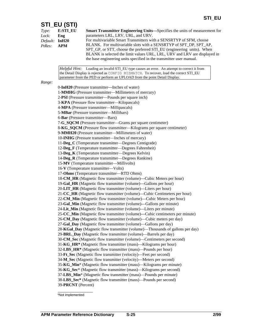
APM Parameter Reference Dictionary S-25 2/99
STI_EUSTI_EU (STI)
Type: E:STI_EULock: EngDefault: InH20PtRes: APM
Smart Transmitter Engineering Units—Specifies the units of measurement forparameters LRL, LRV, URL, and URV.For multivariable Smart Transmitters with a SENSRTYP of SFM, chooseBLANK. For multivariable slots with a SENSRTYP of SPT_DP, SPT_AP,SPT_GP, or STT, choose the preferred STI_EU (engineering units). WhenBLANK is selected the limit values URL, LRL, URV and LRV are displayed inthe base engineering units specified in the transmitter user manual.
Helpful Hint: Loading an invalid STI_EU type causes an error. An attempt to correct it fromthe Detail Display is rejected as CONFIG MISMATCH. To recover, load the correct STI_EUparameter from the PED or perform an UPLOAD from the point Detail Display.
Range:0-InH20 (Pressure transmitter—Inches of water)1-MMHG (Pressure transmitter—Millimeters of mercury)2-PSI (Pressure transmitter—Pounds per square inch)3-KPA (Pressure flow transmitter—Kilopascals)4-MPA (Pressure transmitter—Millipascals)5-MBar (Pressure transmitter—Millibars)6-Bar (Pressure transmitter—Bars)7-G_SQCM (Pressure transmitter—Grams per square centimeter)8-KG_SQCM (Pressure flow transmitter—Kilograms per square centimeter)9-MMH20 (Pressure transmitter—Millimeters of water)10-INHG (Pressure transmitter—Inches of mercury)11-Deg_C (Temperature transmitter—Degrees Centigrade)12-Deg_F (Temperature transmitter—Degrees Fahrenheit)13-Deg_K (Temperature transmitter—Degrees Kelvin)14-Deg_R (Temperature transmitter—Degrees Rankine)15-MV (Temperature transmitter—Millivolts)16-V (Temperature transmitter—Volts)17-Ohms (Temperature transmitter—RTD Ohms)18-CM_HR (Magnetic flow transmitter (volume)—Cubic Meters per hour)19-Gal_HR (Magnetic flow transmitter (volume)—Gallons per hour)20-LIT_HR (Magnetic flow transmitter (volume)—Liters per hour)21-CC_HR (Magnetic flow transmitter (volume)—Cubic Centimeters per hour)22-CM_Min (Magnetic flow transmitter (volume)—Cubic Meters per hour)23-Gal_Min (Magnetic flow transmitter (volume)—Gallons per minute)24-Lit_Min (Magnetic flow transmitter (volume)—Liters per minute)25-CC_Min (Magnetic flow transmitter (volume)—Cubic centimeters per minute)26-CM_Day (Magnetic flow transmitter (volume)—Cubic meters per day)27-Gal_Day (Magnetic flow transmitter (volume)—Gallons per day)28-KGal_Day (Magnetic flow transmitter (volume)—Thousands of gallons per day)29-BRL_Day (Magnetic flow transmitter (volume)—Barrels per day)30-CM_Sec (Magnetic flow transmitter (volume)—Centimeters per second)31-KG_HR* (Magnetic flow transmitter (mass)—Kilograms per hour)32-LBS_HR* (Magnetic flow transmitter (mass)—Pounds per hour)33-Ft_Sec (Magnetic flow transmitter (velocity)—Feet per second)34-M_Sec (Magnetic flow transmitter (velocity)—Meters per second)35-KG_Min* (Magnetic flow transmitter (mass)—Kilograms per minute)36-KG_Sec* (Magnetic flow transmitter (mass)—Kilograms per second)37-LBS_Min* (Magnetic flow transmitter (mass)—Pounds per minute)38-LBS_Sec* (Magnetic flow transmitter (mass)—Pounds per second)39-PRCNT (Percent)______________*Not implemented
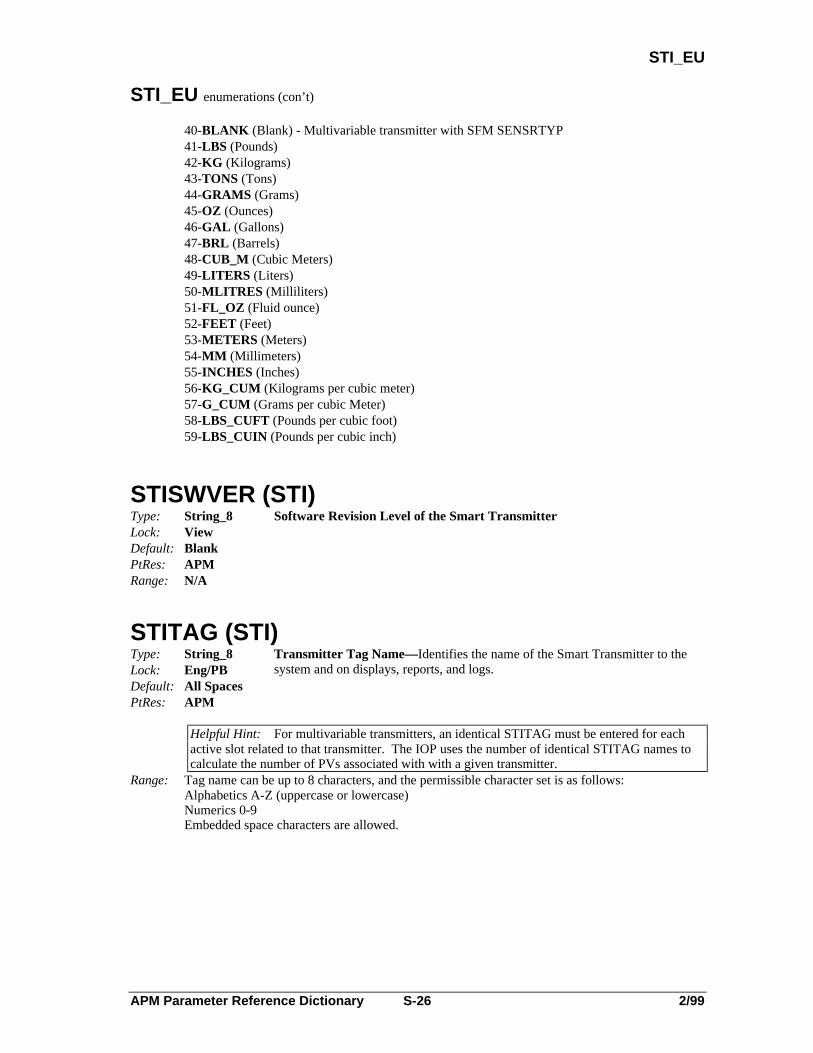
APM Parameter Reference Dictionary S-26 2/99
STI_EU
STI_EU enumerations (con’t)
40-BLANK (Blank) - Multivariable transmitter with SFM SENSRTYP41-LBS (Pounds)42-KG (Kilograms)43-TONS (Tons)44-GRAMS (Grams)45-OZ (Ounces)46-GAL (Gallons)47-BRL (Barrels)48-CUB_M (Cubic Meters)49-LITERS (Liters)50-MLITRES (Milliliters)51-FL_OZ (Fluid ounce)52-FEET (Feet)53-METERS (Meters)54-MM (Millimeters)55-INCHES (Inches)56-KG_CUM (Kilograms per cubic meter)57-G_CUM (Grams per cubic Meter)58-LBS_CUFT (Pounds per cubic foot)59-LBS_CUIN (Pounds per cubic inch)
STISWVER (STI)
Type: String_8Lock: ViewDefault: BlankPtRes: APM
Software Revision Level of the Smart Transmitter
Range: N/A
STITAG (STI)Type: String_8Lock: Eng/PBDefault: All SpacesPtRes: APM
Transmitter Tag Name—Identifies the name of the Smart Transmitter to thesystem and on displays, reports, and logs.
Helpful Hint: For multivariable transmitters, an identical STITAG must be entered for eachactive slot related to that transmitter. The IOP uses the number of identical STITAG names tocalculate the number of PVs associated with with a given transmitter.
Range: Tag name can be up to 8 characters, and the permissible character set is as follows:Alphabetics A-Z (uppercase or lowercase)Numerics 0-9Embedded space characters are allowed.

APM Parameter Reference Dictionary S-27 2/99
STOPFL
STOPFLType: LogicalLock: ProgDefault: OffPtRes: APM
Stop Command Flag—Stops the DigIn accumulator or RegPV totalizer whenthe flag transitions from Off to On.
Range: Off (No effect on the accumulator/totalizer)On (Stops the accumulator/totalizer from counting up/down)
STR8(1)–(16,384) (APM Box)Type: String_8Lock: OperDefault: SpacesPtRes: APM
Box String Variables—The upper bound limit of this array is determined by theNSTRING Box parameter. The LCN index limit is 4095, while no limit existsfor the UCN. Array points may be used to address strings with an index greaterthan 4095.
Range: N/A
STR8(1)–(16) (ProcMod)Type: String_8Lock: Determined by SPLOCK parameterDefault: SpacesPtRes: APM
Local String Variables—Each Process Module point has 16 local STR8variables that are different from the APM Box STR8 variables.
Range: N/A
STR16(1)–(8) (ProcMod)Type: String_16Lock: Determined by SPLOCK parameterDefault: SpacesPtRes: APM
Local String Variables—Each Process Module point has 8 local STR16variables that overlay the local STR8 variables [for example,STR16(1)=STR8(1) concatenated with STR8(2)].
Range: N/A

APM Parameter Reference Dictionary S-28 2/99
STR32
STR32(1)–(4) (ProcMod)Type: String_32Lock: Determined by SPLOCK parameterDefault: SpacesPtRes: APM
Local String Variables—Each Process Module point has four local STR32variables that overlay the local STR8 variables.
Range: N/A
STR64(1)–(2) (ProcMod)Type: String_64Lock: Determined by SPLOCK parameterDefault: SpacesPtRes: APM
Local String Variables—Each Process Module point has two local STR64variables that overlay the local STR8 variables [for example,STR64(1)=STR8(1-8)].
Range: N/A
STR8(i) (Array)Type: String_8Lock: Determined by SPLOCK parameterDefault: N/APtRes: APM
Array Point String Variables—8-character string variables that are mapped to theArray point. The number of variables is dependent on the NSTRING andSTRLEN variables.
Range: 1 ≤ I ≤(Array parameter NSTRING)/(8/STRLEN)
STR16(i) (Array)Type: String_16Lock: Determined by SPLOCK ParameterDefault: N/APtRes: APM
Array Point String Array Variables— 16-character string variables that aremapped to the Array point. These variables overlay the STR8 variables.
Range: 1 ≤ I ≤ (Array parameter NSTRING)/(16/STRLEN)

APM Parameter Reference Dictionary S-29 2/99
STR32(i)
STR32(i) (Array)Type: String_32Lock: Determined by SPLOCK ParameterDefault: N/APtRes: APM
Array Point String Variables—32-character string variables mapped to the Arraypoint that overlay the STR8 variables.
Range: 1 ≤ I ≤ (Array parameter NSTRING)/(32/STRLEN)
STR64(i) (Array)Type: String_64Lock: Determined by SPLOCK ParameterDefault: N/APtRes: APM
Array Point String Variables—64-character string variables mapped to the Arraypoint that overlay the STR8 variables.
Range: 1≤I ≤ (Array parameter NSTRING)/(64/STRLEN)
STRDESC (Array)Type: String_64Lock: PtBldDefault: SpacesPtRes: APM
String Array Descriptor— 64-character string describing the Array point stringdata.
Range: N/A
STRLEN (Array)Type: IntegerLock: PtBldDefault: 8PtRes: APM
Array Point String Length —Indicates the length of the configured string (withthe STRSTIX and NSTRING parameters) displayed on the Array Point Detaildisplay. Strings can be accessed by STR8, STR16, STR32 or STR64 regardlessof this value.
Range: 8, 16, 32, 64
STRLEN (ProcMod)Type: IntegerLock: PtBldDefault: 8PtRes: APM
Process Module String Length—Indicates the displayed string length on theProcess Module Detail display. Strings can still be accessed by STR8, STR16,STR32, or STR64 regardless of this value.
Range: 8, 16, 32, 64

APM Parameter Reference Dictionary S-30 2/99
STRSTIX
STRSTIX (Array)Type: RealLock: PtBldDefault: 0PtRes: APM
String Array Start Index— Defines the string array start index in Box STR8variables, or the Serial Interface-connected device.
Range: 0 to Box parameter NSTRING (When EXTDATA,2B675LQGLFDWHVQRVWULQJVDUHFRQILJXUHG0 to 99,999 (When EXTDATA=IO_STR, 0 can be a valid device index)
STRTFAIL(1)–(6)Type: String_2Lock: ViewDefault:PtRes: APM
Startup/Failover Information
Range: Hexadecimal characters 00 to FF
STSMSGType: E:MSGTXTLock: OperDefault: MSGTXT(0)PtRes: APM
Status Message—A self-defining enumeration of the MSGTXT parameter thatprovides additional descriptive information regarding the red tag, batch state, ordevice state.
Range: MSGTXT(0) to MSGTXT(15)
SUMSLTSZ (APM Box)Type: IntegerLock: ViewDefault: 0PtRes: APM
Total Configured Memory for Sequence Programs—This parameter equals thesum of all Process Module SEQSLTSZ parameters, and is shown on theAPMM Control Configuration display.
Range: >0
SUSPSTAT (ProcMod)Type: E:$SUSPSTLock: ViewDefault: NonePtRes: APM
Suspend State
Range: 0-None2-Feedback3-Wait4-ConfMsg5-InputMsg

APM Parameter Reference Dictionary S-31 2/99
SUSPTIME
SUSPTIME (ProcMod)Type: IntegerLock: ViewDefault: 0PtRes: APM
Suspension Timer—The remaining time (in minutes) before the sequenceprogram resumes execution. This timer is started when a sequence programexecutes a wait statement.
Range: 0 to 32, 767 minutes
SVALDB (DevCtl)Type: E:PVALDBLock: Engr/PBDefault: OnePtRes: APM
SECVAR Alarm Deadband—The deadband for the SECVAR alarm.
Range: 0-Half (1/2 of 1% of Engineering Unit range)1-One (1% of Engineering Unit range)2-Two (2% of Engineering Unit range)3-Three (3% of Engineering Unit range)4-Four (4% of Engineering Unit range)5-Five (5% of Engineering Unit range)6-EU (Value is defined by SVALDBEU parameter)
SVALDBEU (DevCtl)Type: RealLock: Engr/PBDefault: 0.0PtRes: APM
SECVAR Alarm Deadband in Engineering Units—Indicates the alarm deadbandin engineering units when the SVALDB parameter = EU.
Range: Allowable Engineering Units
SVDESC (DevCtl)Type: String_8Lock: PtBldDefault: BlankPtRes: APM
SECVAR Descriptor—Defines the SECVAR parameter or secondary variabledescriptor.
Range: 8 Character String
SVEUDESC (DevCtl)Type: String_8Lock: PtBldDefault: BlankPtRes: APM
SECVAR Engineering Unit Descriptor—Defines the engineering unit descriptorfor the SECVAR parameter or secondary variable descriptor.
Range: 8 Character String
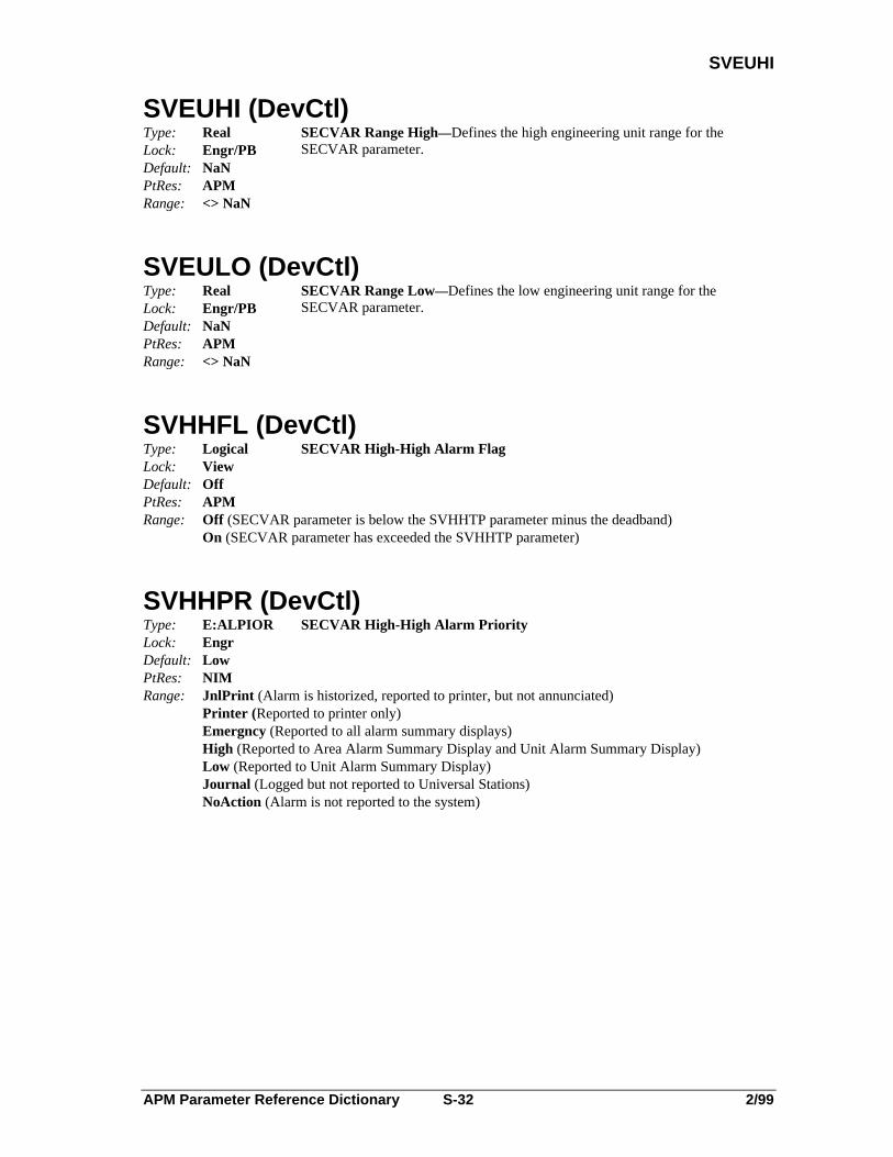
APM Parameter Reference Dictionary S-32 2/99
SVEUHI
SVEUHI (DevCtl)Type: RealLock: Engr/PBDefault: NaNPtRes: APM
SECVAR Range High—Defines the high engineering unit range for theSECVAR parameter.
Range: <> NaN
SVEULO (DevCtl)Type: RealLock: Engr/PBDefault: NaNPtRes: APM
SECVAR Range Low—Defines the low engineering unit range for theSECVAR parameter.
Range: <> NaN
SVHHFL (DevCtl)Type: LogicalLock: ViewDefault: OffPtRes: APM
SECVAR High-High Alarm Flag
Range: Off (SECVAR parameter is below the SVHHTP parameter minus the deadband)On (SECVAR parameter has exceeded the SVHHTP parameter)
SVHHPR (DevCtl)Type: E:ALPIORLock: EngrDefault: LowPtRes: NIM
SECVAR High-High Alarm Priority
Range: JnlPrint (Alarm is historized, reported to printer, but not annunciated)Printer (Reported to printer only)Emergncy (Reported to all alarm summary displays)High (Reported to Area Alarm Summary Display and Unit Alarm Summary Display)Low (Reported to Unit Alarm Summary Display)Journal (Logged but not reported to Universal Stations)NoAction (Alarm is not reported to the system)

APM Parameter Reference Dictionary S-33 2/99
SVHHTP
SVHHTP (DevCtl)Type: RealLock: SuprDefault: NaNPtRes: APM
SECVAR High-High Alarm Trip Point—No alarms are generated when thisparameter is set to NaN.
Range: 69+,73RUNaN
SVHHTPP (DevCtl)Type: RealLock: SuprDefault: NaNPtRes: APM
SECVAR High-High Trip Point Percent—The SECVAR High-High Trip Pointin terms of engineering units in percent.
Range: 0 to 100
SVHIFL (DevCtl)Type: LogicalLock: ViewDefault: OffPtRes: APM
SECVAR High Alarm Flag—This flag is set when the SECVAR exceedsSVHITP and is reset when SECVAR is below SVHIFL minus deadband.
Range: Off (SECVAR parameter is below SVHIFL minus the deadband)On (SECVAR parameter has exceeded SVHIFL)
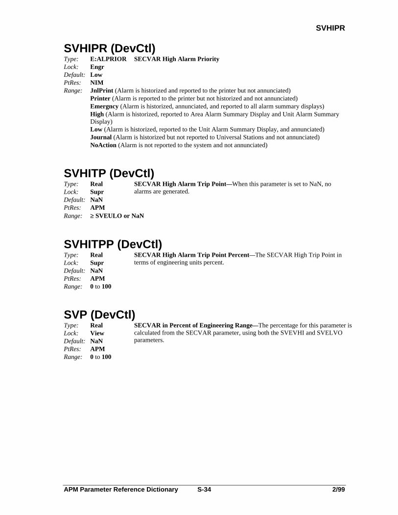
APM Parameter Reference Dictionary S-34 2/99
SVHIPR
SVHIPR (DevCtl)Type: E:ALPRIORLock: EngrDefault: LowPtRes: NIM
SECVAR High Alarm Priority
Range: JnlPrint (Alarm is historized and reported to the printer but not annunciated)Printer (Alarm is reported to the printer but not historized and not annunciated)Emergncy (Alarm is historized, annunciated, and reported to all alarm summary displays)High (Alarm is historized, reported to Area Alarm Summary Display and Unit Alarm SummaryDisplay)Low (Alarm is historized, reported to the Unit Alarm Summary Display, and annunciated)Journal (Alarm is historized but not reported to Universal Stations and not annunciated)NoAction (Alarm is not reported to the system and not annunciated)
SVHITP (DevCtl)Type: RealLock: SuprDefault: NaNPtRes: APM
SECVAR High Alarm Trip Point—When this parameter is set to NaN, noalarms are generated.
Range: ≥ SVEULO or NaN
SVHITPP (DevCtl)Type: RealLock: SuprDefault: NaNPtRes: APM
SECVAR High Alarm Trip Point Percent—The SECVAR High Trip Point interms of engineering units percent.
Range: 0 to 100
SVP (DevCtl)Type: RealLock: ViewDefault: NaNPtRes: APM
SECVAR in Percent of Engineering Range—The percentage for this parameter iscalculated from the SECVAR parameter, using both the SVEVHI and SVELVOparameters.
Range: 0 to 100
APM Parameter Reference Dictionary S-35 2/99
SVPEAK
SVPEAK (DevCtl)Type: RealLock: ViewDefault: NaNPtRes: APM
Peak Value of SECVAR—Indicates the highest value of the SECVAR parametersince the device changed from state 0.
Range: Real or NaN
SVSRC (DevCtl)Type: Universal
Ent.PrmLock: PtBldDefault: NullPtRes: APM
SECVAR Input Connection—Specifies input connection to which the currentvalues of Device Control inputs are supplied. The connection can be specifiedusing the "Tagname.Parameter" format or the hardware reference address formatRefer to the APM Control Functions and Algorithms manual for a detaileddescription.
Range: Use Tagname.Parameter for tagged points where Tagname can be up to 16 characters and thepermissible character set is as follows:
Alphabetics A-Z (uppercase only)Numerics 0-9 (an all numeric tag name is not allowed)Underscore (_) cannot be used as the first character or the last character, and consecutive underscores are not allowed.Embedded space characters are not allowed.An * is used to default to this point’s tag name.Parameter name can be up to eight characters and must be a legitimate parameter name.
Some possible input-connection sources area."Logic slot Tagname.NN(nn)" where nn = 1–8b."ProcMod slot Tagname.NN(nnn)" where nnn = 1–80c."Box Numerics slot Tagname.NN” where nnnnn = 1-16,384d."!Box.FL(nnnn)" for a box flag that resides in the same box where nnnn = 1–16,384
Use the hardware reference address !MTmmSss.Parameter for untagged or tagged points whereMT is the IOP type, such as AI (Analog Input)mm is the IOP Card number (1–40)The letter "S" is a constantss is the slot number on the IOP Card (refer to SLOTNUM parameter)Parameter name can be up to eight characters and must be a legitimate parameter name.
SVTV (DevCtl)Type: RealLock: OperDefault: NaNPtRes: APM
Secondary Variable Target Value—Indicates the normal or operating setpoint forthe SECVAR parameter.
Range: SVEULO to SVEUHI
APM Parameter Reference Dictionary S-36 2/99
SVTVP
SVTVP (DevCtl)Type: RealLock: OperDefault: NaNPtRes: APM
Secondary Variable Target Value in Percent—Indicates the normal or operatingsetpoint for the SECVAR parameter as a percent.
Range: 0 to 100
SWTCHACT (1)–(40) (APM Box)Type: LogicalLock: ViewDefault: OnPtRes: APM
IOP Synchronization—When this parameter is Off (inactive), the backup requestline from the IOP's partner is not asserted. When this parameter is On (active),the backup request line from the IOP's partner is asserted.
Range: On-ActiveOff-Inactive
SYNCHSTS(1)–(40) (APM Box)Type: E:$SYNCHSTLock: ViewDefault: NonePtRes: APM
Primary/secondary Database Synchronization Status. It is set to WARNINGwhen a database inconsistency is first detected, but the secondary appearscapable of providing backup. It changes to FAIL when the APMM has triedto resync but does not succeed or a secondary failure prevents synchronization.nn = 1–40 corresponds to the 40 logical I/O modules.Applies to primary IOP only.
Range: 0-OK - (the secondary is synchronized with theprimary and can provide backup if necessary.)1-WARNING - (database inconsistency detectedbut secondary can probably provide backup).2-FAIL - (APMM has tried to resynchronize buthas not succeeded or, secondary has also failed).

APM Parameter Reference Dictionary T-1 2/99
T
-T-
T (FlowComp)Type: RealLock: ViewDefault: 1.0PtRes: APM
Temperature Input—Indicates the measured actual temperature.
Range: > 0.0
T0 (FlowComp)Type: RealLock: SuprDefault: 0.0PtRes: APMRange: N/A
Zero Reference for Temperature—T0 is the zero reference temperature input andit is in the same engineering units as the T (measured actual temperature) input.T0 is typically -459.69 degrees F or -273.15 degrees C. Enter the absolute valueof the temperature.
T1Type: RealLock: SuprDefault: 0.0 minutesPtRes: APM
Integral Time in Minutes—Defines the integral time constant inminutes-per-repeat.
Range: 0.0 to 1440.0 minutes
Helpful Hint: Integral action can be disabled by setting T1 equal to 0.0.
T2Type: RealLock: SuprDefault: 0.0 minutesPtRes: APM
Derivative Time in Minutes—Defines the derivative time constant.
Range: 0.0 to 1440.0 minutes
Helpful Hint: Derivative action can be disabled by setting T2 equal to 0.0
TCRNGOPTType: E:$TCRNGOPLock: Eng/PBDefault: NormalPtRes: APM
Thermocouple Range Option—Defines the thermocouple range option.Applies only if a thermocouple (TC) sensor type is used for this data point.
Range: 0-Normal (Use PVEXEULO’s normal range table)1-Extended (Use PVEXEULO’s extended range table)
Helpful Hint: TCRNGOPT configuration requires IOTYPE = LLAI or LLMUX, or RHMUX and SENSRTYP = Thermcpl. Refer to parameter PVEXEULO.

APM Parameter Reference Dictionary T-2 2/99
TD
TD (VdtLdLag)Type: RealLock: SuprDefault: 0.0PtRes: APM
Total Dead Time in Minutes—Defines the fixed delay time in minutes forequation B, and the actual variable delay time in minutes for equations C and D.
Range: > 0.0 minutes
TFType: RealLock: SuprDefault: 0.0 minutesPtRes: APM
PV Filter Lag Time in Minutes—Defines the filtering time lag to be used afterthe PV range has been checked. A value of 0.0 specifies that the PV is notdelayed.
Range: 0.0 to 60.0 minutes
TIME(1)–(4095) (APM Box)Type: TimeLock: OperDefault: 0 secondsPtRes: APM
Box Time Variables—The upper limit of this array is determined by the NTIMEparameter. The LCN index limit is 4,095, while the limit on the UCN is 4096.Array points may be used to address Times with an index greater than 4095.
Range: N/A
TIME(i) (Array)Type: TimeLock: Determined by SPLOCK parameterDefault: N/APtRes: APM
Array Point Time Variables—Times are mapped from the APM Box defined bythe TIMESTIX and NTIME parameters.
Range: 1 ,$UUD\SDUDPHWHU17,0(
TIME(1)–(4) (ProcMod)Type: TimeLock: Determined by SPLOCK ParameterDefault: 0 secondsPtRes: APM
Local Time Variables—Four local Time variables are available in each ProcessModule point. These variables are different than the APM Box Time variables.
Range: N/A
TIMEBASE (Timer)Type: E:TIMEBASELock: EngrDefault: SecondsPtRes: APM
Time Base—Defines the time base to be used for the Timer data point.
Range: 0-Seconds1-Minutes

APM Parameter Reference Dictionary T-3 2/99
TIMEBASE
TIMEBASE (Totalizr, PI)Type: E:TIMEBASELock: Eng/PBDefault: MinutesPtRes: APM
Totalizer Time Base—Defines whether time base is in seconds, minutes, orhours.
Range: 0-Seconds (PV and Setpoint engineering units (gallons, etc.) per second)1-Minutes (PV and Setpoint engineering units (gallons, etc.) per minute)2-Hours (PV and Setpoint engineering units (gallons, etc.) per hour)
TIMEDESC (Array)Type: String_64Lock: PtBldDefault: SpacesPtRes: APM
Time Array Descriptor— Sixty four-character string describing Time data.
Range: N/A
TIMESECS(1)–(240) (Array)Type: TimeLock: Determined by SPLOCK parameterDefault: N/APtRes: APM
Array Point Time Variables—Times mapped from the APM box defined byTIMESTIX and NTIME parameters.
Range: 1 i 17,0($UUD\SDUDPHWHU
TIMESTIX (Array)Type: RealLock: PtBldDefault: 0PtRes: APM
Time Array Start Index— Defines the Time data start index in the BoxTime variables.
Range: 0 to Box parameter NTIME (0 indicates there are no Times configured for this point)
TIMESYNC (UCN)Type: E:ENBLSTATLock: PtBldDefault: DisablePtRes: NIM
Timesynch Control—Defines whether SOE timesynch can be performed bythis NIM or NIM pair. Normally, the NIM with the lowest address isconfigured for this function.
Range: Enable (This NIM or NIM pair is able to perform SOE time synchronization)Disable (This NIM or NIM pair does not perform SOE time synchronization, but can receive and
report SOE events)
TLD (VdtLdLag)Type: RealLock: SuprDefault: 0.0 minutesPtRes: APM
Lead Time Constant in Minutes—Defines the lead-compensation time constantin minutes. A 0 (zero) entry specifies no lead compensation.
Range: -1440.0 to 1440.0 minutes
APM Parameter Reference Dictionary T-4 2/99
TLG1, TLG2
TLG1, TLG2 (VdtLdLag)Type: RealLock: SuprDefault: 0.0 minutesPtRes: APM
Lag Time Constant
Range: 0.0 to 1440.0 minutes (0 specifies no lag compensation)
TMCMD(1)–(64) (APM Box)Type: E:COMMANDLock: OperDefault: N/APtRes: APM
Timer Command—An array of commands issued to the 64 Timer data points.
Range: 0-None (A command has not been issued to the timer)1-Start (Starts the timer)2-Stop (Stops the timer)3-Reset (Resets the timer to 0)4-RestStrt (Resets the timer to 0, and starts the timer)
TMPV(1)–(64) (Timer)Type: IntegerLock: ViewDefault: 0PtRes: APM
Timer PV—Indicates the current (elapsed) time of the Timer data point inseconds or minutes.
Range: >0
TMRV(1)–(64) (Timer)Type: IntegerLock: ViewDefault: 0PtRes: APM
Timer RV— Indicates the remaining time (TMSP minus TMPV) for the Timerdata point.
Range: >0
TMSO(1)–(64) (Timer)Type: LogicalLock: ViewDefault: OffPtRes: APM
Timer Status Output—Indicates the current state of the timer output.
Range: Off (TMPV 7063HODSVHGWLPHKDVQRWUHDFKHGWKHSUHVHWWLPHOn (TMPV = TMSP; elapsed time has reached the preset time)
TMSP(1)–(64) (Timer)Type: IntegerLock: OperDefault: 0PtRes: APM
Timer Setpoint—Defines the preset time of the Timer data point, in seconds orminutes.
Range: 0 to 32000
APM Parameter Reference Dictionary T-5 2/99
TMST(1)–(64)
TMST(1)–(64) (Timer)Type: E:STATELock: ViewDefault: StoppedPtRes: APM
Timer State—Indicates the current state of the Timer data point.
Range: 0-Stopped (Timer is currently stopped)1-Running (Timer is currently running)
TMTB(1)–(64) (Timer)Type: E:TIMEBASELock: EngrDefault: SecondsPtRes: APM
Timer Time Base—Defines the time base of the timer.
Range: 0-Seconds1-Minutes
TRACKINGType: LogicalLock: Eng/PBDefault: OffPtRes: APM
Selected Input Tracking—Allows the selected input to be changed withoutbumping the output.
Range: Off (Tracking disabled)On (Tracking is to be used)
Helpful Hint: If On, causes nonselected inputs to track the selected input.
TRANTIM0–2 (DevCtl, DigComp)Type: TimeLock: ViewDefault: 0PtRes: APM
Transition Time—The date and time of the most recent transition to each statebased on the PV.
Range: Time Stamp
TRATAVG (NIM, APM Box)Type: RealLock: ViewDefault: NaNPtRes: APM
Average UCN Transaction Trip Time—The average UCN transaction trip timein milliseconds for both fetch and store responses from this node to otherUCN nodes.
Range: N/A
Helpful Hint: This statistic can be viewed on the Toolkit Displays
APM Parameter Reference Dictionary T-6 2/99
TRATMAX
TRATMAX (NIM, APM Box)Type: RealLock: ViewDefault: NaNPtRes: APM
Maximum UCN Transaction Trip Time— The maximum UCN transaction triptime in milliseconds for both fetch and store responses from this node to otherUCN nodes.
Range: N/A
Helpful Hint: This statistic can be viewed on the Toolkit Displays.
TRFB (PidErfb)Type: RealLock: ViewDefault: NaNPtRes: APM
Tracking Feedback Input in Engineering Units—Indicates the value of the PV orSP of another data point that is receiving its setpoint from this data point.
Range: N/A
TSTS (FlowComp)Type: E:PVVALSTLock: ViewDefault: NormalPtRes: APM
Temperature Input Value Status—Status of the T input value.
Range: 0-Bad (Value is bad and replaced with NaN)1-Uncertn (Status of the value is uncertain)2-Normal (Value is good)
TVPROC (RegCtl)Type: E:TVPROCLock: OperDefault: OffPtRes: APM
Target Value Processor State
Range: 0-Off (No target value processing)1-Preset (Set up setpoint target value and ramp time)2-Run (Perform ramping function)
Helpful Hint: TVPROC applies only if SPOPT = TV.
APM Parameter Reference Dictionary U-1 2/99
UCNRECHN
-U-
UCNRECHN (APM Box, NIM)Type: E:$RECCHNLock: ViewDefault: ChannelAPtRes APM, NIM
UCN Receive Channel—Indicates the channel to which the node is listening.
Range: 0-ChannelA1-ChannelB
UCNSCANT (APM Box)Type: Real Peer-to-Peer Scan Period in secondsLock: Eng/PBDefault: 0.5PtRes: APMRange: 0.5, 1.0
UCNSFREVType: IntegerLock: ViewDefault: N/APtRes APM
UCN Software Revision
UCNSFVERType: IntegerLock: ViewDefault: N/APtRes APM
UCN Software Version

APM Parameter Reference Dictionary U-2 2/99
UNCMDFL
UNCMDFL (DevCtl, DigComp)Type: LogicalLock: ViewDefault: OffPtRes APM
Uncommanded Change Alarm Flag—Indicates whether an uncommanded changehas been detected in the field device. (Field device has changed its state withouta command.)
Range: Off (No uncommanded change alarm)On (Uncommanded change alarm has been detected by this point)
UNITType: String_2Lock: PtBldDefault: N/APtRes NIM
Unit Identifier— Defines the process unit to which this point is assigned. Theunit identifier is originally assigned during network configuration, and it appearsin displays and listings throughout the system.
Restriction: Two characters are required; blanks are not allowed. For example,unit 3 must be entered as 03.
CL and Picture Editor — An integer is returned. This number is equivalent tothe unit position in the Unit Names configuration list.
Range: A-Z, 0-9 (up to 100 unit IDs can be configured)
UPGRADE (UCN)Type: E:UPGRADELock: OperDefault: OKPtRes NIM
NIM Upgrade Status
Range: OK (NIM has not been upgraded and is OK)Upgrade (NIM is upgraded and is questionable)
APM Parameter Reference Dictionary U-3 2/99
URL
URL (STI)Type: RealLock: Eng/ViewDefault: NaNPtRes: APM
Upper Range Limit—Indicates the upper range limit of the PV at the SmartTransmitter. This limit is a fixed limit and cannot be changed. Refer to thedescription of the STI_EU parameter for the URL engineering units. Duringconfiguration, the value entered for this parameter must agree with the URLvalue of the transmitter. Although any value can be entered duringconfiguration, a database mismatch will occur when the point is put on-processbecause the transmitter’s URL value and the STI IOP’s URL value are not thesame. If the values are not the same, the STATE parameter value becomesDBChange and PVSTS becomes Bad. Refer to URL in the PM/APM SmartlineTransmitter Integration Manual for more information.
The corresponding LRL parameter is not a configurable parameter at theUniversal Station.
The upper range limits for the Smart Transmitters are as follows:
For the ST3000 Smart Pressure Transmitters (Spt_Dp, Spt_Gp and Spt_Ap):
Xmtr Range URL (In H2O)
400 inH2O 400.0600 inH2O 600.0780 mmHga 400.0100 PSI 2768.0200 PSI 5536.13500 PSI/A 13840.341500 PSI 41521.02000 PSI 55361.353000 PSI 83042.026000 PSI 166084.0
10000 PSI 276806.7
For the STT3000 Smart Temperature Transmitter (Stt):
Sensor Type URL(PVCHAR) (in Degrees C except where noted)
Linear (mV) 1000 MvThermocouples:
B 1820E 1000J 1200K 1370NiNiMoTC 1300N 1300R 1760S 1760T 400W5W26TC 2300W3W25TC 2300
APM Parameter Reference Dictionary U-4 2/99
URVRTDs:
Cu10RTD 250Cu25RTD 250DINRTD 850JISRTD 640NicklRTD 150Pt200 850Pt500 850RHRad 1800RTD (ohms) 4000
For the MagneW 3000 Magnetic Flowmeter (Sfm):
URL (in meters3/hour) = '2
4x106 x 3600 x (N + 1)
where: D = the detector diameter in millimeters as follows: 2.5, 5, 10, 15, 25,40, 50, 80, 100, 150, 200, 300, 350, 400, 500, 600, or 700
N = the number of dummy submerged detectors, from 0 to 9Range: N/A, NaN
URV (STI) Type: RealLock: Supr/ViewDefault: NaNPtRes: APMRange: N/A, NaN
Upper Range Value—Defines the upper end of the operating range for thePVRAW value. Refer to the description of the STI_EU parameter for the URVengineering units.
Although the following maximum values can be entered, values greater than theURL are not recommended and accuracy is not guranteed in such cases.
For a pressure transmitter (Spt): URVmax = 2.0 x URLFor a temperature transmitter (Stt): URVmax = 2.0 x URLFor a magnetic flow transmitter (Sfm): URVmax = 12.0 x URL
This parameter is a view-only parameter when the STI point execution statePTEXECST is Active (indicating that changes cannot be made in this parametervalue from the Universal Station).
USERIDType: String_16Lock: OperDefault: DashesPtRes APM
User ID Reservation—The user ID that currently has reserved this point. Theuser can be changed by either a point, program, or operator. The operator canoverwrite the USERID parameter at anytime. A program can store a nonblankstring in this parameter only if it is blank. If the USERID string starts withthree or more dashes (- - -), only the operator can overwrite the ID.
Range: 16 Character String
UTSDRIFT (APM Box, NIM)Type: IntegerLock: ViewDefault: N/APtRes APM, NIM
UCN Node Clock Drift—Indicates the current APMM clock drift rate, calculatedby averaging the LCN clock interval and SYNCH CLOCK interval overmultiple synchs. Averaging does not occur until UCN time synchronization isin a steady state.
Range:
APM Parameter Reference Dictionary U-5 2/99
UTSNODE
UTSNODE (APM Box, NIM)Type: IntegerLock: ViewDefault: 0PtRes APM, NIM
Last UCN Syncher Node—Describes which node is the synch master orsyncher. Normally, this is the primary NIM, even though the secondary NIMcan also be the syncher. The syncher function performs periodic timesynchronization on the UCN.
Range: 0, 1 to 64 (0 specifies No Syncher Node)
UTSTBCRV (APM Box, NIM)Type: String_2Lock: ViewDefault: N/APtRes APM, NIM
TBC Revision—The token bus controller revision number in hexidecimalformat.
Range: 5 to 15
UTSTIME (APM Box, NIM)Type: TimeLock: ViewDefault: N/APtRes APM, NIM
Current Time in LCN Node—Identifies the current time of day for this LCNnode, and is useful if there are multiple LCNs or UCNs.
Range: N/A
UTSTIMST (APM Box, NIM)Type: E:$UCNTMSTLock: ViewDefault: 0PtRes APM, NIM
Timesynch State of the UCN Node—The state of time synchronizationfor each UCN node.
Range: 0-Initial (Waiting for the first complete synch operation)1-Failed (The maximum amount of time has elapsed and no synch operation has occurred, or the
NIM does not have a functioning EPNI board)2-Degraded (In nonsyncher NIMs and APMMs, an excessive amount of time has elapsed without
a complete synch operation. In APMMs, the drift limit between the LCN andAPMM clock has been exceeded)
3-LCN_Bad (Synch operations are taking place on a regular basis, but the NIM’s clock is notsynched with the LCN)
4-LCN_OK (Synch operations are occurring regularly and the NIM’s clock is properly synchedwith the LCN)
5-OK (Synch operations are working in an optimal manner)

APM Parameter Reference Dictionary U-6 2/99

APM Parameter Reference Dictionary W-1 2/99
WARMSTRT(1)–(168)
-W-
WARMSTRT(1)–(168)Type: LogicalLock: ViewDefault:PtRes IOP
Warm Start Flag
Range: On (Warm start executed)Off (Cold start executed)
WEEKDAY (APM Box)Type: IntegerLock: ViewDefault: N/APtRes APM
Current Weekday—The current weekday based on LCN wall clock time.
Range: 1 to 7 (Sunday to Saturday)
WITHBIAS(1)–(40) (APM Box)Type: LogicalLock: ViewDefault: ONPtRes APM
I/O Module Physical Bias State—ON Indicates that the preferredprimary is really the acting primary; OFF indicates that it is not.For IOPs that do not have hardware bias (e.g., HLAI, DI, etc.),the status of ON is always returned. Applies to primary IOP only.
Range: On (The preferred primary is the acting primary)Off (The preferred primary is not the acting primary)

APM Parameter Reference Dictionary W-2 2/99

APM Parameter Reference Dictionary X-1 2/99
X
-X-
X (FlowComp)Type: RealLock: ViewDefault: 1.0PtRes APMRange: > 0.0
Steam Compressibility Input—Indicates the measured actual steamcompressibility.
X1(AutoMan)Type: RealLock: ProgDefault: NaNPtRes APM
X1 Input Value to be Biased
Range: NaN
X1–4 (IncrSum, ORSel)Type: RealLock: ProgDefault: NaNPtRes APM
Inputs 1-4—Current values of the inputs to this algorithm.
Range: > 0.0, NaN
X2(AutoMan)Type: RealLock: ViewDefault: N/APtRes APM
Bias Adjustment Input
Range: N/A
X2 (RatioCtl)Type: RealLock: ViewDefault: N/APtRes APM
Input Number 2—Indicates the value of the uncontrolled process variable.Source should be the same as for P2 of the Calcultr algorithm, if it is being usedin conjunction with the Calcultr algorithm.
Range: N/A
APM Parameter Reference Dictionary X-2 2/99
X2FILT
X2FILT (RatioCtl)Type: RealLock: ViewDefault: N/APtRes APM
Filtered value of the X2 input
Range: N/A
Helpful Hint: Filter time is determined by X2TF. This filter is only active if the point is inthe AUTO or CASC mode.
X2TF (RatioCtl)Type: RealLock: SuprDefault: 0.0PtRes APM
X2 input filter lag time in minutes
Range: 0 - 60 minutes
XEUHI (AutoMan, IncrSum, ORSel)Type: RealLock: EngrDefault: 100.0
(equivalentto 100%)
PtRes APM
X Input Engineering Unit High Range—Defines the upper limit of the value ofthe X input or inputs.
Range: > XEULO
XEULO (AutoMan, IncrSum, ORSel)Type: RealLock: EngrDefault: 0.0 (equivalent to 0%)PtRes APM
X Input Engineering Unit Low Range—Defines the lower limit of the value ofthe X input or inputs.
Range: < XEUHI
XSTS (FlowComp)Type: E:PVVALSTLock: ViewDefault: NormalPtRes APM
X Input Value Status—Status of the steam compressibility input.
Range: 0-Bad (Value is bad and replaced with NaN)1-Uncertn (Status of the value is uncertain)2-Normal (Value is good)

APM Parameter Reference Dictionary Y-1 2/99
YEAR
-Y-
YEAR (APM Box)Type: IntegerLock: ViewDefault: N/APtRes APMRange: 1979 to 2115
Current Year— The value of the LCN date in the APM.

APM Parameter Reference Dictionary Y-2 2/99

FAX Transmittal FAX No.: (602) 313-4842
TO: Andrea Simmons Total FAX pages:(including this page)
Reader CommentsTitle of Document: Advanced Process Manager Parameter Reference Dictionary
Document Number: AP09-640 Issue Date: 2/99
Comments:
Recommendations:
FROM:Name: Date:
Title:
Company:
Address:
City: State: ZIP:
Telephone: FAX:
FOR ADDITIONAL ASSISTANCE:Write Call
Honeywell Inc.Industrial Automation and Control
Automation College2820 West Kelton Lane
Phoenix, AZ 85053-3028
Technical Assistance Center (TAC)1-800-822-7673 (48 contiguous states except Arizona)
602-313-5558 (Arizona)


Industrial Automation and Control
Automation College
2820 W. Kelton Lane
Phoenix, AZ 85023-3028