Advanced Pressure Vessel Manual - mechshop.ir · software license agreement 1. license this is a...
198
A A d d v v a a n n c c e e d d P P r r e e s s s s u u r r e e V V e e s s s s e e l l ©1997-2008 Computer Engineering, Inc. All Rights Reserved Worldwide Manual Version: 2007-10.0 Web Site www.computereng.com
Transcript of Advanced Pressure Vessel Manual - mechshop.ir · software license agreement 1. license this is a...
AAddvvaanncceedd PPrreessssuurree VVeesssseell
©1997-2008 Computer Engineering, Inc. All Rights Reserved Worldwide
Manual Version: 2007-10.0
Web Site www.computereng.com

ii
Copyright Notice Advanced Pressure Vessel is copyrighted by Computer Engineering, Inc. (CEI). All rights are reserved worldwide. This manual is also copyrighted and all rights are reserved. This document may not, in whole or part, be copied, photocopied, reproduced, translated, or reduced to any electronic medium of machine-readable form without prior consent in writing from Computer Engineering, Inc. CEI may make improvements and changes to both this manual and the program at any time.
Trademark Notice Advanced Pressure Vessel, Advanced Tower Design, Zick Saddles & Seismic, Legs Lugs & Seismic, FormPro, Welding Pro-Write, Advanced Welding System, and Welder Management System are trademarks of Computer Engineering, Inc. Microsoft, Microsoft Windows, Windows 2000, Windows XP and Windows Vista are registered trademarks of the Microsoft Corporation. BDE, and Borland Database Engine are trademarks or registered trademarks of Borland Corp. ASME® is the Trademark of the American Society of Mechanical Engineers. National Board® is the Trademark of the National Board® of Boiler and Pressure Vessel Inspectors. AWS® is the Trademark of the American Welding Society. All other trademarks are the property of their respective owners.
iii
Software License Agreement 1. LICENSE THIS IS A LICENSE AGREEMENT AND NOT AN AGREEMENT FOR SALE. PLEASE READ THIS LICENSE AGREEMENT (“AGREEMENT”) CAREFULLY AND BE SURE YOU ACCEPT IT’S TERMS BEFORE YOU OPEN THE ENVELOPE. IF YOU (as defined hereunder) OPEN THE ENVELOPE AND/OR DOWNLOAD THE SOFTWARE AND/OR INSTALL THE SOFTWARE ON YOUR COMPUTER AND/OR USE THE SOFTWARE, THIS WILL SIGNIFY THAT YOU CONSENT TO BE BOUND BY THE TERMS OF THIS AGREEMENT AND THE APPLICABLE PORTIONS OF ALADDIN KNOWLEDGE SYSTEM’S® DEVELOPER’S LICENSE AGREEMENT, MICROSOFT’S® SQL SERVER 2000 DESKTOP ENGINE LICENSE AGREEMENT, AND MICROSOFT’S® MICROSOFT® AGENT LICENSE AGREEMENT (ACCESSIBLE AT WWW.COMPUTERENG.COM) AS THEY MAY APPLY. IF YOU DO NOT AGREE WITH THE TERMS AND CONDITIONS OF THESE AGREEMENTS, DO NOT OPEN THE ENVELOPE, DO NOT INSTALL THE SOFTWARE ON YOUR COMPUTER, AND RETURN THE SOFTWARE AND ALL ASSOCIATED MATERIALS IN FULL WORKING ORDER WITHIN 10 BUSISNESS DAYS FROM THE DATE OF PURCHASE TO RECEIVE A REFUND IN THE AMOUNT YOU PAID (MINUS ANY APPLICABLE SHIPPING AND HANDLING). COMPUTER ENGINEERING grants a license to the Person or Entity (“YOU/YOUR”) that has opened the envelope, downloaded the SOFTWARE, installed the SOFTWARE on a computer, and/or used the SOFTWARE and YOU accept a nonexclusive license to use the SOFTWARE and related materials, including but not limited to any hardware locking/licensing devices (“HARDWARE KEY(S)”), delivered with this AGREEMENT for YOUR exclusive internal use and purposes subject to the terms and conditions of this AGREEMENT. For the purposes of this document, a SEAT is defined as one concurrent instance of the SOFTWARE. A LAN (local area network) is defined as a system that links together electronic office equipment, such as printers, workstations, and server(s), and forms a network within a single office or building. A WAN (wide area network) will be defined by workstation connection type, as follows: Leased line, Broadband (DSL, Cable, ISDN, etc.), Dial-up (56k or slower connections), or any other wired network connection outside of the building containing the network server. There are technological measures in this SOFTWARE that are designed to prevent unlicensed or illegal use of the SOFTWARE. YOU agree that COMPUTER ENGINEERING may use those measures. Any attempt to circumvent said measures, regardless of outcome, on any COMPUTER ENGINEERING SOFTWARE may result in the revocation of all of YOUR licenses to operate any and all COMPUTER ENGINEERING SOFTWARE and the suspension of any and all technical and logistical support by COMPUTER ENGINEERING, at COMPUTER ENGINEERING’s sole discretion. Through periodic updates or other means, YOU may receive multiple copies of the SOFTWARE. Any copies of the SOFTWARE acquired in such a manner, or via any other means, are provided to you on a license exchange basis. YOU may only use the copies of the SOFTWARE that are appropriate to YOUR license (see Section 2 of this AGREEMENT). YOU may not use any additional/elapsed copies of the SOFTWARE on another system or network, nor may those copies of the SOFTWARE be loaned, rented, leased, or transferred to any other party. The acceptance of this AGREEMENT for any SOFTWARE that was licensed to YOU with a discount based, in whole or in part, on a prior AGREEMENT between YOU and COMPUTER ENGINEERING for said SOFTWARE, shall terminate that prior AGREEMENT and this AGREEMENT shall be in force in its stead. Any previous versions used as the basis for such a discount which were previously classified as “Multi-user” or “LAN Pack” versions now must comply with the below LAN Seat stipulations (see Section 2 of this AGREEMENT). The supplied HARDWARE KEY contains, and is therefore the embodiment of, YOUR SOFTWARE’S license. Its replacement, including any costs or fees levied by Computer Engineering for said replacement, is YOUR exclusive responsibility. This policy applies regardless of cause, including but not limited to: loss, theft, physical damage, or the rendering of said device inoperable through any means. 2. OUR RIGHTS COMPUTER ENGINEERING retains all intellectual property rights to the SOFTWARE including all trademarks and copyrights. YOU agree not to transfer the SOFTWARE in any form to any party without the prior written consent of COMPUTER ENGINEERING. The assent or prohibition of said consent shall be solely at the discretion of COMPUTER ENGINEERING with the understanding that the receiving party in such a circumstance must consent to be bound by the terms of this AGREEMENT. Except as provided in this AGREEMENT, YOU may not sublicense, lease, rent, time-share, lend or provide commercial hosting services related to the SOFTWARE or any related materials or any of YOUR rights under this AGREEMENT except by prior written consent from COMPUTER ENGINEERING. YOU may not alter, decompile, reverse engineer, disassemble, reverse translate or in any other way derive any source code or proprietary database information from the SOFTWARE. YOU may not remove, obscure, or alter YOUR company name or serial number in either hardcopy (including, but not limited to, printed documents and reports) or machine-readable portions (including, but not limited to, SOFTWARE files, files created by the SOFTWARE, and electronic files) of the SOFTWARE except with prior written consent from COMPUTER ENGINEERING. The assent or prohibition of said consent shall be solely at the discretion of COMPUTER ENGINEERING. YOU acknowledge and agree that due to the nature of the proprietary information contained within the SOFTWARE, there can be no adequate remedy at law for any breach of the obligations hereunder, which breach may result in irreparable harm. Upon any such breach or any threat thereof, COMPUTER ENGINEERING shall be entitled to appropriate equitable relief in addition to whatever remedies it might have at law. COMPUTER ENGINEERING is permitted the right to audit YOUR use of the SOFTWARE, both electronically and physically, by providing no less than (5) days prior written or electronic notice of its intention to conduct a physical audit of YOUR facilities during normal business hours. Electronic audits require no such notice and are preformed at the sole discretion of COMPUTER ENGINEERING. In the event that such audit reveals any use of the SOFTWARE by YOU other than that specified by the terms of this AGREEMENT, YOU shall reimburse COMPUTER ENGINEERING for expenses related to such audit in addition to any other liabilities
iv
YOU may incur as a result of such non-compliance. Through the course of supporting the SOFTWARE our technical support department may require that system information relating to the computers on which the SOFTWARE and/or HARDWARE KEY are installed be sent through electronic means. This support information will remain private. This is the only agreement between YOU and COMPUTER ENGINEERING. It cannot and shall not be modified unless in writing and signed by both YOU (or an authorized officer of YOUR company) and an authorized officer of COMPUTER ENGINEERING. 3. YOUR RIGHTS COMPUTER ENGINEERING warrants the HARDWARE KEY and physical media on which the SOFTWARE is distributed to be free from defects in material and workmanship upon receipt. Demonstration/Lite versions of the SOFTWARE may be used on any system by any number of users. Single-seat versions of the SOFTWARE, and the associated HARDWARE KEY, may be used only on a single personal computer or single workstation at a time. Program data files may be stored remotely or locally and may be shared between multiple Single Seat Licenses. The installation or use of the SOFTWARE or HARDWARE KEY on the Internet or over a WAN, including, without limitation, use in connection with Web hosting, terminal server, or remote access software of any kind is expressly forbidden. Campus, Corporate, and International Corporate versions of the SOFTWARE are subject to their own specific license agreements. 4. WARRANTY COMPUTER ENGINEERING PROVIDES THE SOFTWARE “AS IS” WITHOUT WARRANTY OF ANY KIND, EITHER EXPRESSED OR IMPLIED, INCLUDING, BUT NOT LIMITED TO, THE IMPLIED WARRANTIES OF FITNESS FOR A PARTICULAR PURPOSE. COMPUTER ENGINEERING SHALL NOT BE LIABLE FOR ANY TORT, INDIRECT, PUNITIVE, SPECIAL, OR CONSEQUENTIAL DAMAGES SUCH AS LOSS OF PROFITS, OR LOSS OF GOODWILL FROM THE USE OR THE INABILITY TO USE THE SOFTWARE FOR ANY PURPOSE OR THE PROVISION OF, OR FAILURE TO PROVIDE, ANY SERVICE, SOFTWARE OR CONTENT, EVEN IF COMPUTER ENGINEERING HAS BEEN ADVISED OF THE POSSIBILITY OF SUCH DAMAGE. ALSO, THERE IS NO WARRANTY OR CONDITION OF TITLE, QUIET ENJOYMENT, QUIET POSSESSION, OR CORRESPONDENCE TO DESCRIPTION. SOME STATES DO NOT ALLOW THE EXCLUSION OF IMPLIED WARRANTIES SO THIS LANGUAGE MAY NOT APPLY TO YOU. IN SUCH CASE, COMPUTER ENGINEERING'S LIABILITIES SHALL BE LIMITED TO A REFUND OF THE SOFTWARE'S PURCHASE PRICE. COMPUTER ENGINEERING PROVIDES NO WARRANTY THAT THE SOFTWARE DOES NOT INFRINGE ANY PATENTS OR OTHER INTELLECTUAL PROPERTY OF THIRD PARTIES AND WILL NOT INDEMNIFY YOU IF YOU ARE CHARGED WITH PATENT INFRINGEMENT OR INFRINGEMENT OF ANY OTHER INTELLECTUAL PROPERTY HELD BY THIRD PARTIES. This AGREEMENT applies to any and all updates, supplements, add-on components, or Internet-based components, of the SOFTWARE that COMPUTER ENGINEERING may provide to YOU or make available to YOU after the date YOU obtain YOUR initial copy of the SOFTWARE, unless COMPUTER ENGINEERING provides other terms along with said update, supplement, add-on component, or Internet-based component. This AGREEMENT supersedes all prior or contemporaneous agreements or understandings, whether oral or written. The failure or delay of COMPUTER ENGINEERING to exercise any or all of its rights under this AGREEMENT or upon any infringement of this AGREEMENT shall not be deemed a waiver of those rights or of said infringement. COMPUTER ENGINEERING reserves all rights not expressly granted. COMPUTER ENGINEERING reserves the right to discontinue any Internet-based services provided to YOU or made available to YOU through the use of the SOFTWARE. 5. OTHER You acknowledge that the SOFTWARE is of U.S. origin and subject to U.S. export jurisdiction. You agree to comply with all applicable international and national laws that apply to the SOFTWARE, including the U.S. Export Administration Regulations, as well as end-user, end-use, and destination restrictions issued by U.S. and other governments. This AGREEMENT shall be governed by the laws of the State of Missouri and shall inure to the benefit of COMPUTER ENGINEERING, its successors, and assigns. The invalidity or unenforceability of any provisions of this AGREEMENT shall not affect the remaining provisions hereof. Note: If this copy of the SOFTWARE is designated as a “Leased” license, the following paragraph also applies to YOU: This SOFTWARE is made available for the Leased period for which you have paid and will cease to operate on the expiration of that Lease period. Use of this SOFTWARE after that expiration or any attempt to defeat the disabling function in any manner, is a violation of this AGREEMENT. COMPUTER ENGINEERING, INC. Blue Springs, MO www.computereng.com
v
Additional Warranty Computer Engineering, Inc., warrants the distribution media to be free of defects in material and workmanship on receipt. In the event of notification within the warranty period of defects in material or workmanship, Computer Engineering, Inc., will replace the defective media. Computer Engineering, Inc., warrants the satisfaction of this program to the original purchaser. If you are not satisfied within ten (10) days, return the manual and media with License for a full refund, less shipping and handling and a restocking fee. Please contact Computer Engineering, Inc., for a Return Material Authorization (RMA) number. Shipping and handling is non-refundable. Software must be uninstalled to the satisfaction of Computer Engineering, Inc. No returns will be accepted without prior written authorization from Computer Engineering, Inc., and in no case will return authorization be granted after ten (10) days from date of purchase.
Disclaimer Advanced Pressure Vessel is a software tool designed to assist engineers by generating calculations for pressure vessel design. It should not be used to design pressure vessels without the guidance of a knowledgeable engineer. It was never intended to be, or marketed as an all-inclusive pressure vessel design program. Due to the complex nature of engineering, there are many external factors that need to be taken into account and are beyond the scope of Advanced Pressure Vessel and its add-in modules. Many of these factors are, at times, outside the coverage of the ASCE, ANSI, UBC and IBC codes. Codes developed by standards committees, such as the ASME®, rely on the use of sound engineering practices to fill these gaps in procedure. Paragraph U-2 (g) of the ASME® Section VIII, Division 1 Code states that the ASME® Code for Section VIII does not contain rules to control all details of design and construction. Where details are incomplete it is the manufacturer’s responsibility, subject to the Authorized Inspector’s acceptance, to use good engineering judgment for the details of design and construction. Since Advanced Pressure Vessel performs calculations based on the rules of Section VIII Division 1 per U-2 (g) it cannot, by definition, complete all of the calculations necessary to design every possible pressure vessel configuration. U-2 (b)(1) also states that it is the responsibility of the manufacturer of a vessel or any part of a vessel marked with a Code symbol to insure that it is in compliance with the ASME® Code and good engineering practice. In addition to the software warranty, Computer Engineering, Inc., makes every attempt to test Advanced Pressure Vessel and verify its calculations by hand. Computer Engineering, Inc., is not responsible for errors in the calculations or any consequential damage due
vi
to poor engineering judgment or oversight in vessels designed using the software. This philosophy is consistent with the ASME’s current attitude toward software-assisted design. Computer Engineering, Inc., strives to provide the highest quality software possible at an affordable price. Absolutely no software program can replace an engineer. Advanced Pressure Vessel assumes that the user has a working knowledge of the ASME® Code and sound mechanical engineering skills or experience. If you have any questions regarding the software or its calculation abilities, please feel free to contact us.
vii

viii
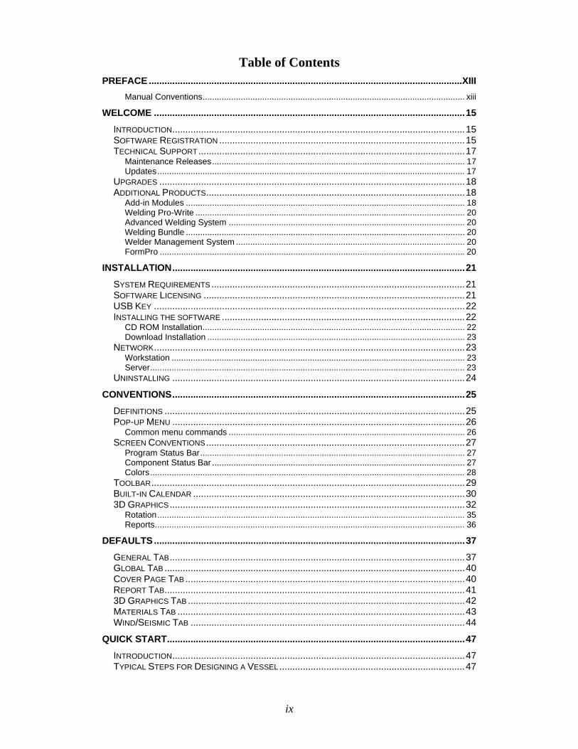
Table of Contents PREFACE ........................................................................................................................XIII
Manual Conventions.............................................................................................................. xiii WELCOME .......................................................................................................................15
INTRODUCTION................................................................................................................15 SOFTWARE REGISTRATION ..............................................................................................15 TECHNICAL SUPPORT......................................................................................................17
Maintenance Releases.......................................................................................................... 17 Updates................................................................................................................................. 17
UPGRADES .....................................................................................................................18 ADDITIONAL PRODUCTS...................................................................................................18
Add-in Modules ..................................................................................................................... 18 Welding Pro-Write ................................................................................................................. 20 Advanced Welding System ................................................................................................... 20 Welding Bundle ..................................................................................................................... 20 Welder Management System ................................................................................................ 20 FormPro ................................................................................................................................ 20
INSTALLATION................................................................................................................21 SYSTEM REQUIREMENTS .................................................................................................21 SOFTWARE LICENSING ....................................................................................................21 USB KEY .......................................................................................................................22 INSTALLING THE SOFTWARE .............................................................................................22
CD ROM Installation.............................................................................................................. 22 Download Installation ............................................................................................................ 23
NETWORK.......................................................................................................................23 Workstation ........................................................................................................................... 23 Server.................................................................................................................................... 23
UNINSTALLING ................................................................................................................24 CONVENTIONS................................................................................................................25
DEFINITIONS ...................................................................................................................25 POP-UP MENU ................................................................................................................26
Common menu commands ................................................................................................... 26 SCREEN CONVENTIONS...................................................................................................27
Program Status Bar............................................................................................................... 27 Component Status Bar .......................................................................................................... 27 Colors.................................................................................................................................... 28
TOOLBAR........................................................................................................................29 BUILT-IN CALENDAR ........................................................................................................30 3D GRAPHICS.................................................................................................................32
Rotation................................................................................................................................. 35 Reports.................................................................................................................................. 36
DEFAULTS .......................................................................................................................37 GENERAL TAB.................................................................................................................37 GLOBAL TAB ...................................................................................................................40 COVER PAGE TAB ...........................................................................................................40 REPORT TAB...................................................................................................................41 3D GRAPHICS TAB ..........................................................................................................42 MATERIALS TAB ..............................................................................................................43 WIND/SEISMIC TAB .........................................................................................................44
QUICK START..................................................................................................................47 INTRODUCTION................................................................................................................47 TYPICAL STEPS FOR DESIGNING A VESSEL.......................................................................47
ix
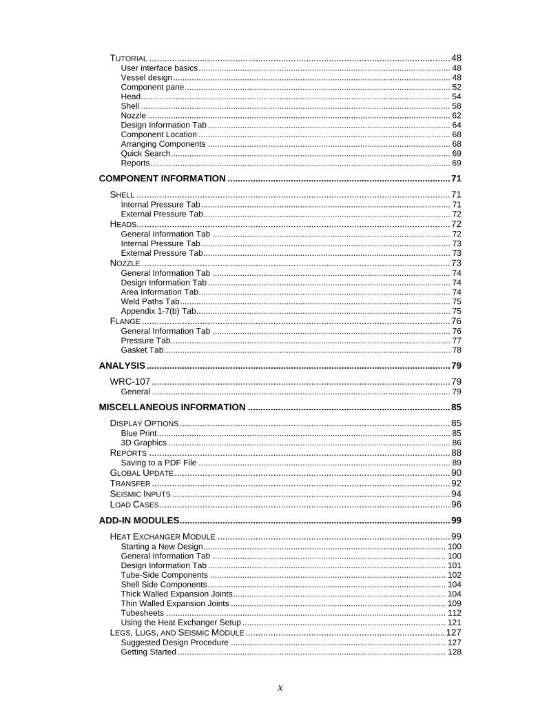
TUTORIAL .......................................................................................................................48 User interface basics............................................................................................................. 48 Vessel design........................................................................................................................ 48 Component pane................................................................................................................... 52 Head...................................................................................................................................... 54 Shell ...................................................................................................................................... 58 Nozzle ................................................................................................................................... 62 Design Information Tab ......................................................................................................... 64 Component Location ............................................................................................................. 68 Arranging Components ......................................................................................................... 68 Quick Search......................................................................................................................... 69 Reports.................................................................................................................................. 69
COMPONENT INFORMATION ........................................................................................71 SHELL ............................................................................................................................71
Internal Pressure Tab............................................................................................................ 71 External Pressure Tab........................................................................................................... 72
HEADS............................................................................................................................72 General Information Tab ....................................................................................................... 72 Internal Pressure Tab............................................................................................................ 73 External Pressure Tab........................................................................................................... 73
NOZZLE ..........................................................................................................................73 General Information Tab ....................................................................................................... 74 Design Information Tab ......................................................................................................... 74 Area Information Tab............................................................................................................. 74 Weld Paths Tab..................................................................................................................... 75 Appendix 1-7(b) Tab.............................................................................................................. 75
FLANGE ..........................................................................................................................76 General Information Tab ....................................................................................................... 76 Pressure Tab......................................................................................................................... 77 Gasket Tab............................................................................................................................ 78
ANALYSIS ........................................................................................................................79 WRC-107 ......................................................................................................................79
General ................................................................................................................................. 79 MISCELLANEOUS INFORMATION ................................................................................85
DISPLAY OPTIONS...........................................................................................................85 Blue Print............................................................................................................................... 85 3D Graphics .......................................................................................................................... 86
REPORTS .......................................................................................................................88 Saving to a PDF File ............................................................................................................. 89
GLOBAL UPDATE.............................................................................................................90 TRANSFER ......................................................................................................................92 SEISMIC INPUTS ..............................................................................................................94 LOAD CASES...................................................................................................................96
ADD-IN MODULES...........................................................................................................99 HEAT EXCHANGER MODULE ............................................................................................99
Starting a New Design......................................................................................................... 100 General Information Tab ..................................................................................................... 100 Design Information Tab ....................................................................................................... 101 Tube-Side Components ...................................................................................................... 102 Shell Side Components....................................................................................................... 104 Thick Walled Expansion Joints............................................................................................ 104 Thin Walled Expansion Joints ............................................................................................. 109 Tubesheets ......................................................................................................................... 112 Using the Heat Exchanger Setup ........................................................................................ 121
LEGS, LUGS, AND SEISMIC MODULE...............................................................................127 Suggested Design Procedure ............................................................................................. 127 Getting Started .................................................................................................................... 128
x
General Information Tab ..................................................................................................... 128 Wind and Seismic Info Tab, General Sub-Tab .................................................................... 128 Leg ...................................................................................................................................... 131 Lug and Support Rings........................................................................................................ 135 Attachments/Loadings......................................................................................................... 138 Leg Methodology................................................................................................................. 143
TOWER MODULE ...........................................................................................................145 Important Information .......................................................................................................... 145 Suggested Design Procedure ............................................................................................. 146 Getting Started .................................................................................................................... 147 General Information Tab ..................................................................................................... 147 Wind and Seismic Info Tab, General Sub-Tab .................................................................... 148 Design Components............................................................................................................ 149 Skirt and Intermediate Supports.......................................................................................... 151 Base Plate........................................................................................................................... 152 Attachments/Loadings......................................................................................................... 156 Tower Analysis Basics ........................................................................................................ 161 Definitions ........................................................................................................................... 161 Methodology........................................................................................................................ 162
ZICK, SADDLES, & SEISMIC MODULE ..............................................................................164 Important Information .......................................................................................................... 164 Suggested Design Procedure ............................................................................................. 165 Getting Started .................................................................................................................... 166 Wind and Seismic Info Tab, General Sub-Tab .................................................................... 167 Design Components............................................................................................................ 168 Attachments/Loadings......................................................................................................... 170 Saddle design ..................................................................................................................... 173
DESIGN GUIDES............................................................................................................185 STIFFENING RING..........................................................................................................185 FLANGE RIGIDITY ..........................................................................................................187 TUBESHEET ..................................................................................................................189 WEAR PLATE VS. TOP FLANGE ......................................................................................192
APPENDIX......................................................................................................................193 BIBLIOGRAPHY ..............................................................................................................193 FREQUENTLY ASKED QUESTIONS...................................................................................195
General Questions .............................................................................................................. 195 Vessel Questions ................................................................................................................ 196
xi

xii
Preface
Welcome to Advanced Pressure Vessel. This manual is intended to complement the extensive help system. The chapters in this manual are presented in an order intended to help new users understand the program as quickly as possible.
Manual Conventions This manual is designed for printing on 8 1/2” x 11” paper or A4 paper. If you want additional copies of the manual you may print them from the Microsoft Word document or Adobe PDF document that were installed in the main program directory. Keystrokes are designated by a [square bracket] around keyboard keys and the keys are bold. For example, the Escape key is shown as [Esc] and function key F1 is shown as [F1]. Graphics are placed in the margin for emphasis. The following graphics and their meaning are: Help or Technical Support. Warning – Be careful. Something that is noteworthy is mentioned in the paragraph. A mouse command is discussed in the paragraph. Additional information is discussed in the paragraph. Network information.
xiii

xiv
Welcome
Introduction Advanced Pressure Vessel is a sophisticated engineering program that will assist in the design of pressure vessels in accordance with the ASME® Boiler and Pressure Vessel Code, Section VIII Division 1. Whatever ASME® Code proficiency the user has, Advanced Pressure Vessel will increase productivity. Advanced Pressure Vessel does not profess to take the place of a design engineer, but assists in the design process. We make the assumption that the engineer has a working knowledge of the ASME® Boiler and Pressure Vessel Code and knowledge of engineering principles. Computer Engineering has been dedicated to providing our customers with high quality welding and engineering software for more than two decades. We strive to maintain a customer-oriented atmosphere wherein software may be developed, maintained, and distributed with customer satisfaction as the driving force. To meet that objective, a well-trained staff is utilized to develop new programs, update existing programs, and provide technical support. An important facet of any computer program is reliability. Our software is thoroughly tested for usability as well as ASME® Code requirements. Quality control is taken very seriously at Computer Engineering. Satisfying the needs of our customers is a core principle of our philosophy at CEI. We will do everything in our power to create a product that is accurate, reliable, and beneficial to our customers. We encourage you to contact us with your comments and suggestions regarding any of our products, as well as those about programs you would like to have available.
1
Software Registration Completion of the on-line product registration process ensures that you are eligible for the benefits available, such as special offers, updates, and upgrades. By registering, you can also receive free technical support until 60 days after the next Update is available.
- 15 -

Remember that registering your copy of Advanced Pressure Vessel also lets us know where to send update information and other important information as it becomes available.
- 16 -
Technical Support Program help and ASME® Code references are available throughout the program through the use of function key [Fl] or clicking on the “Help” toolbar button. Detailed information on the use of the program is contained in the help system. If additional help or information is needed, contact CEI through one of the following methods: e-mail: [email protected] FAX: 1 (877) 228-0680 (toll free inside the US) VOICE: 1 (816) 228-2976 Technical Support hours are posted online at Computer Engineering’s Website. Technical support is also available through our web site at:
www.computereng.com
Maintenance Releases The latest revisions and maintenance releases are available at the web site. In addition, information about training classes and demonstration programs can be found there. Maintenance releases are free for the current version. You can also receive the latest revision through the internet by using Live Update. This can be accessed by clicking the Windows Start button, Programs, Computer Engineering, Advanced Pressure Vessel, Live! Update. After starting Live! Update, your software will be checked for any Maintenance Releases. If a Maintenance Release is available, follow the instructions on the screen Alternately, CEI’s web site can be accessed directly at www.computereng.com. Once on the web site, click Downloads, Maintenance Releases, and manually search the site for any maintenance releases that may be available.
Updates Updates are changes to the software that accommodate new ASME® Code Addenda or Code books. Updates are available for purchase before the changes become mandatory. As a registered user, you will be sent notification when these updates are available. The Update fee varies from year to year depending upon the number of changes to the program. The Update fee includes free technical support and free website maintenance revisions made to the program until the next Update is available. Technical Support is available until 60 days after the next Update is released.
- 17 -
Upgrades There are several Upgrades available for Advanced Pressure Vessel. Please contact the sales department if you want to upgrade:
To add LAN Seats (multiple users at one location) To a campus license (multiple buildings at a single site) To a corporate license
Additional Products Computer Engineering provides software to assist engineers and quality control personnel in many facets of their jobs. This includes vessel design, welding, and data reports.
Add-in Modules There are four add-in modules available for Advanced Pressure Vessel. By offering add-in modules, the user can pick which features they need. The ability to choose modules saves unnecessary cost since you only purchase what you need. You can purchase “Pressure Vessel Suite,” which includes the first three modules, at a substantial savings. All modules except Heat Exchanger have the ability to perform wind and seismic analysis. Wind analysis and seismic shear calculations can be performed in accordance with ASCE/ANSI, the International Building Code (IBC), or with user specified data. The add-in modules available are:
Zick, Saddles, & Seismic (ZSS) – This module calculates stresses in horizontal vessels resting on saddle supports according to Zick’s analysis. You can also design saddles, thereby saving on materials instead of relying on “standard” design table specifications. Multiple configurations of saddle design are possible; for example, a variable contact angle from 90° to 180°, with or without a wear plate, can be designed. Base plate, wear plate, web, and stiffener thickness can be calculated for your specific requirements. Weight calculations are performed from user specified data, such as vessel diameter, length, wall thickness, head type, insulation, liquid level & density, and attachments. Calculations for stiffening rings and concrete foundation stresses may also be performed.
- 18 -
Legs, Lugs, & Seismic (LLS) – This module calculates component stresses for vessels supported by unbraced legs, support lugs, or support rings attached to shells. Leg support calculations determine bending and compressive stresses, maximum bending and comprehensive stresses for worst case and specified angles for up to twelve leg supports and several different leg configurations. Calculations for support lugs determine lug reaction, gusset reaction, moments about base plate, maximum and allowable weld stresses, shell stress induced by supports, and shell buckling stress. Ring support calculations determine maximum stresses and bending moments at gusset locations and between gusset locations. Gusset stresses and shell buckling stresses are also calculated. Leg support configurations include pipe, angle, w-beam, t-bar, channel, and tube. Lug support configurations include single or double gusset with or without top plate. Ring support configurations include single or double gusset with or without top ring.
Advanced Tower Design (ATD) – This module calculates component
stresses for tall tower vessels supported by base plates and skirts. It determines an accurate weight distribution for the vessel and calculates the First Natural Period of Vibration (FNPV) based on Rayleigh’s un-dampened beam method utilizing superposition. Seismic shear force is calculated utilizing the FNPV and the included or user specified seismic data. Base plate configurations include base ring only, base ring with gussets only, base ring with centered anchor bolt, base ring with gussets and continuous compression ring, and base ring with gussets and compression plate (anchor bolt chair). Cylindrical and conical skirts may also be designed.
Heat Exchanger (HE) – (Not bundled with Pressure Vessel Suite).
This module performs calculations for heat exchangers under the mandatory Part UHX of the ASME® Section VIII Division 1 Code. U-tube tubesheets, fixed tubesheets, and floating tubesheets are calculated per Part UHX. Tube to tubesheet welds may be calculated per Part UHX or Appendix A. Design calculations for thick-walled expansion joints—both flanged and flued or flanged only—are completed per Appendix 5. Design calculations for thin-walled expansion joints are performed per Appendix 26. “Heat Exchanger Setup” allows you to quickly design vessels based on standard TEMA configurations. Simply pick the components from a list, and the program creates the heat exchanger for you. Tweak a few variables and your design is completed.
- 19 -
Welding Pro-Write Welding Pro-Write is consistently the most widely used, best selling welding management and documentation program. In addition to maintaining individual welder continuity, it also makes quick work of writing accurate WPS’s, PQRs, & WPQs in accordance with the ASME® Code. The program also includes brazing in accordance with the ASME® Code. This fast, easy-to-use program eliminates errors and mind-numbing table references because Code-checking, compliant to the latest ASME® Section IX guidelines, and a massive materials database are built right in. Like all of our welding software, Welding Pro-Write has the highest level of Code-checking available in the industry. If you perform welds in accordance with AWS D1.1 as well, please take a look at our Welding Bundle.
Advanced Welding System Advanced Welding System is a program designed to generate fully Code-checked WPQs, PQRs, and WPS’s in compliance with AWS D1.1 (including lightning fast pre-qualified WPS’s under Section 3). A full complement of welder management features as well as a materials database is included. Just like all of Computer Engineering’s welding software, Advanced Welding System contains the highest level of Code-checking in the industry. If you perform welds in accordance with ASME Section IX Code as well, please take a look at our Welding Bundle.
Welding Bundle Welding Bundle is a combination that includes a license for both Welding Pro-Write Enhanced and Advanced Welding System at a substantial savings.
Welder Management System When you don’t need the ability to create procedures, Welder Management System is the perfect choice. You can create fully Code-checked WPQs in accordance with the ASME Section IX and AWS D1.1 Codes, as well as maintaining your welders’ qualifications. The management reports included are worth the price of the program alone. They can help you find the right welder for every job, track defect percentages, and make sure you don’t let a welder’s qualification expire, resulting in a costly re-qualification!
FormPro Electronically create clean, accurate data reports in accordance with ASME® or National Board® specifications. Templates, defaults and dropdowns help you fill reports in a fraction of the time normally required. Some versions will even import data from Advanced Pressure Vessel to save even more of your valuable time. P, H, U, A, & R forms are available in various combinations to suit virtually any budget.
- 20 -
Installation
Please read the entire installation chapter before attempting to install the software. If you are installing a LAN Seat or desire to keep the data on a server, there is a section in this chapter devoted to networking.
System Requirements Advanced Pressure Vessel has the following system requirements:
Windows 2000 or Windows XP Approximately 60 Megabytes of storage space. Processor: Min. – Pentium 266, Recommended – Pentium IV 2.0 GHz. Memory: Min. – 128 Megabytes, Recommended – 512 Megabytes One (1) USB port
2
Software Licensing Computer Engineering takes software piracy very seriously. And we will take measures to protect our copyrighted intellectual property. Most people are unaware that when you purchase software, unless it is specifically stated in a written agreement, you are purchasing the right to use the software under certain restrictions imposed by the copyright owner. The rules imposed by the copyright owner are listed in the License Agreement.
Most people are also unaware of the various types of software piracy. End User piracy is when a copy of a software program is reproduced without authorization. This includes copying the software from one computer to multiple computers, copying the distribution media, taking advantage of upgrade offers without having a legal copy of the version to be upgraded, using academic or other restricted versions for commercial use and swapping media in or outside the workplace. Hard disk loading piracy occurs when a copy or an image of a hard drive is made. Then the pirate “pushes” that image to other computers without a license for the copyrighted software. And finally, software counterfeiting occurs when the illegal duplication and sale of copyright material with the intent of directly imitating a copyrighted product. For more information on software piracy see www.bsa.org/usa/antipiracy/. United States copyright laws carry stiff penalties for violators. If the government prosecutes a violator for copyright infringement and they are convicted they could face fines up to $250,000 US dollars and/or a jail sentence of up to 5 years.
- 21 -
Additionally, the copyright owner can bring a civil suit against the violator where they can purse the following course of action. 1) Have the violator immediately stop using the software, 2) Request monetary damages up to $150,000 U.S. dollar per pirated copy of the software.
USB Key A USB Key is a hardware device that contains software license information. A USB Key is provided for protection against unauthorized use of the software. Protecting against unauthorized use allows Computer Engineering to keep your costs as low as possible. The USB Key must be connected to the computer when running the program(s). If it is disconnected while a program that requires the key is running, the program will change to Demonstration mode. The USB Key is the embodiment of your software license(s); therefore, it is YOUR responsibility to insure it for the full replacement value of the license(s) contained within.
Installing the software CD ROM Installation After inserting the CD, a browser for installing your CEI software should be displayed. Click “Vessel Design” to display a list of program groups that are available for installation. Click on “Advanced Pressure Vessel” and select “Install”. If the browser does not start automatically, use Windows Explorer to start it by double clicking on “START.EXE” in the root directory of the CD. For example, if the CD ROM drive is D: then the root directory would be “D:\”. To install Advanced Pressure Vessel without using the CD Browser, use Windows Explorer and double click on “SETUP.EXE” located in the “X:\Advanced Pressure Vessel\Install\Standard” folder of the CD (X represents the letter of the CD-ROM drive). To install the software, you must have administrator privileges and be logged in as the user that will run the software. It may be necessary to temporarily elevate a user’s rights to Administrator during installation. After the program is installed, the rights may be decreased to Power User. If you experience any problems during the installation please disable anti-virus software and attempt to reinstall.
- 22 -
Download Installation You may download the latest version of Advanced Pressure Vessel from our web site (www.computereng.com) and install the program directly from the download.
Note
We recommend whenever possible that the data and support files be installed on the server. If this is a LAN Seat License, we require the data and support files to be installed on the server. The Application files will always be installed on a workstation.
The installation program defaults to installing Advanced Pressure Vessel on the “C:” drive in the “Program Files”, “CEI” folder, and in a subfolder named to correspond to the current version. These settings may be changed to the desired drive and path during the initial installation setup. The installation program will uncompress and copy program files to the designated directories. We strongly recommend the program be installed in the default directory. DO NOT install it in a previous year’s directory. Doing this may corrupt the databases!
Network Advanced Pressure Vessel is shipped network ready. The single user version is licensed for a single user on a single workstation. LAN Seat versions are available that allow multiple simultaneous users at a single physical location to operate the program, each on their own workstations with the Hardware Key inserted, while the Data and Support files are stored on a central file server.
Workstation To minimize network traffic and to improve performance, it is required that program files be installed on local computers. The vessel data files and supporting databases are then stored on a file server. This allows all users to have access to the vessel designs and current supporting data.
Server After installation of the required files on the server, the network administrator must insure all users have the following privileges for the directories where files are stored:
Read Write Create
- 23 -
Delete All data and support databases are encrypted in order to maintain vessel design integrity. There are two files created on the server titled “PDOXUSRS.NET” and “PDOXUSRS.LCK”. This is where information regarding the files and record locking is maintained. DO NOT DELETE THESE FILES WHILE THE PROGRAM IS IN USE!
Uninstalling Should it become necessary to remove Advanced Pressure Vessel from the computer, select the Windows Control Panel and “Add/Remove Programs”. Highlight Advanced Pressure Vessel with the appropriate version number and click on the Add/Remove button.
- 24 -
Conventions
Data input screens are designed like a notebook with tabs for various sections of data. Each tab can have a different pop-up menu or set of keystrokes, depending upon the component being designed.
3 Definitions The following terms are presented here to help clarify the manual and the usage of the program.
Browser A pop-up screen that allows selection of an item. Browsers are used for such things as selecting a material for use in a vessel component.
Database A file or files where information is stored.
Pop-up Menu A menu that is displayed by clicking on the right mouse button. Pop-up menus are used extensively in the program.
Record One item of a table. For example, SA-516, Grade 70 in the Material database is a record.
Vessel Component A part of the vessel such as a head, a nozzle, or a ring stiffener.
Host Component A part of the vessel such as a shell or head that can have an attachment like a nozzle or a ring stiffener.
Subcomponent A part of the vessel such as a nozzle or ring stiffener; both of which attach to a host component like a shell.
- 25 -
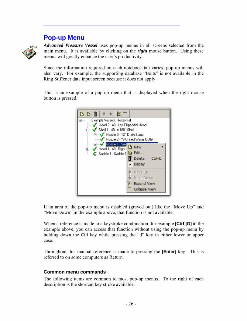
Pop-up Menu Advanced Pressure Vessel uses pop-up menus in all screens selected from the main menu. It is available by clicking on the right mouse button. Using these menus will greatly enhance the user’s productivity. Since the information required on each notebook tab varies, pop-up menus will also vary. For example, the supporting database “Bolts” is not available in the Ring Stiffener data input screen because it does not apply. This is an example of a pop-up menu that is displayed when the right mouse button is pressed.
If an area of the pop-up menu is disabled (grayed out) like the “Move Up” and “Move Down” in the example above, that function is not available. When a reference is made to a keystroke combination, for example [Ctrl][D] in the example above, you can access that function without using the pop-up menu by holding down the Ctrl key while pressing the “d” key in either lower or upper case. Throughout this manual reference is made to pressing the [Enter] key. This is referred to on some computers as Return.
Common menu commands The following items are common to most pop-up menus. To the right of each description is the shortcut key stroke available.
- 26 -
New – [Ctrl] [N] – Creates a new record. The user will be placed in the
new record for data input. Delete – [Ctrl] [D] – Deletes the current record. Copy – [Alt] [C] – Copies the current vessel component or current
record. After the copy is complete, the user will be placed in the new record in edit mode. If you copy a complete vessel you will NOT be placed in the new vessel for editing!
Save – [Ctrl] [S] -- Writes current information to the hard disk and returns the user to the form in edit mode. When a design screen is exited, the data is automatically saved.
Cancel – [Esc] – When adding a record, Cancel assumes the user no longer wants to add a record and exits to the main menu. When editing a record, Cancel will undo all changes since the last save and keep the user in the data entry form in edit mode.
Exit – [Alt] [F4] – Leave the current data screen and save changes. Refresh – [Ctrl] [R] – Used in a network situation. This will update
the screen with the most current information from the shared data.
Screen Conventions The following conventions are used throughout Advanced Pressure Vessel.
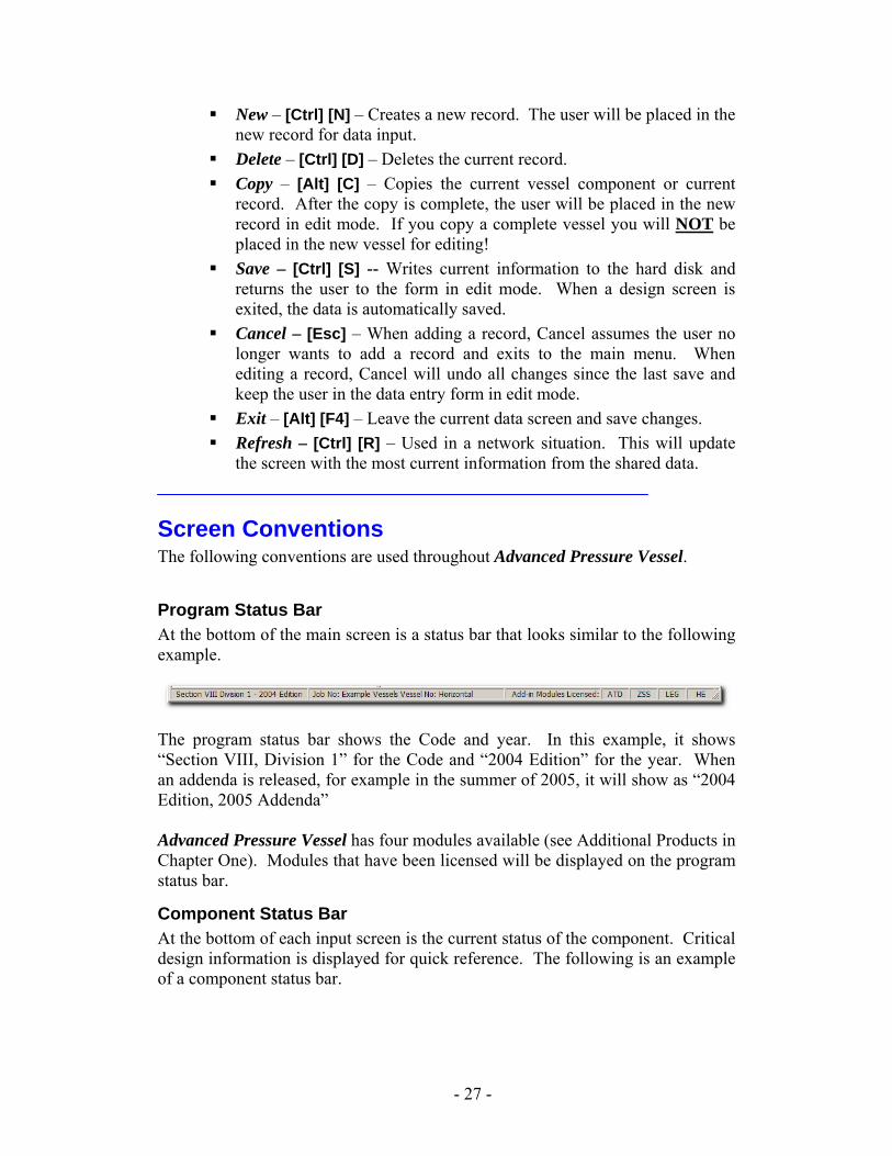
Program Status Bar At the bottom of the main screen is a status bar that looks similar to the following example.
The program status bar shows the Code and year. In this example, it shows “Section VIII, Division 1” for the Code and “2004 Edition” for the year. When an addenda is released, for example in the summer of 2005, it will show as “2004 Edition, 2005 Addenda” Advanced Pressure Vessel has four modules available (see Additional Products in Chapter One). Modules that have been licensed will be displayed on the program status bar.
Component Status Bar At the bottom of each input screen is the current status of the component. Critical design information is displayed for quick reference. The following is an example of a component status bar.
- 27 -
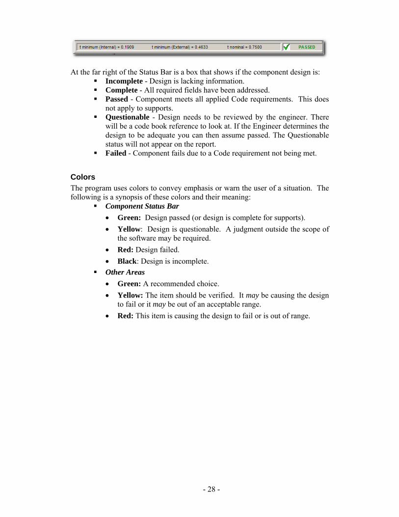
At the far right of the Status Bar is a box that shows if the component design is: Incomplete - Design is lacking information. Complete - All required fields have been addressed. Passed - Component meets all applied Code requirements. This does
not apply to supports. Questionable - Design needs to be reviewed by the engineer. There
will be a code book reference to look at. If the Engineer determines the design to be adequate you can then assume passed. The Questionable status will not appear on the report.
Failed - Component fails due to a Code requirement not being met.
Colors The program uses colors to convey emphasis or warn the user of a situation. The following is a synopsis of these colors and their meaning:
Component Status Bar • Green: Design passed (or design is complete for supports). • Yellow: Design is questionable. A judgment outside the scope of
the software may be required. • Red: Design failed. • Black: Design is incomplete.
Other Areas • Green: A recommended choice. • Yellow: The item should be verified. It may be causing the design
to fail or it may be out of an acceptable range. • Red: This item is causing the design to fail or is out of range.
- 28 -
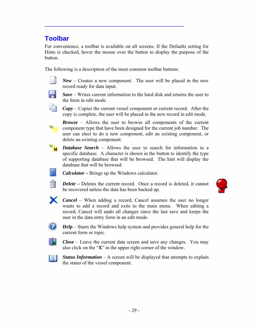
Toolbar For convenience, a toolbar is available on all screens. If the Defaults setting for Hints is checked, hover the mouse over the button to display the purpose of the button. The following is a description of the most common toolbar buttons:
New – Creates a new component. The user will be placed in the new record ready for data input.
Save – Writes current information to the hard disk and returns the user to the form in edit mode.
Copy – Copies the current vessel component or current record. After the copy is complete, the user will be placed in the new record in edit mode.
Browse – Allows the user to browse all components of the current component type that have been designed for the current job number. The user can elect to do a new component, edit an existing component, or delete an existing component.
Database Search – Allows the user to search for information in a specific database. A character is shown in the button to identify the type of supporting database that will be browsed. The hint will display the database that will be browsed.
Calculator – Brings up the Windows calculator.
Delete – Deletes the current record. Once a record is deleted, it cannot be recovered unless the data has been backed up.
Cancel – When adding a record, Cancel assumes the user no longer wants to add a record and exits to the main menu. When editing a record, Cancel will undo all changes since the last save and keeps the user in the data entry form in an edit mode.
Help – Starts the Windows help system and provides general help for the current form or topic.
Close – Leave the current data screen and save any changes. You may also click on the “X” in the upper right corner of the window.
Status Information – A screen will be displayed that attempts to explain the status of the vessel component.
- 29 -
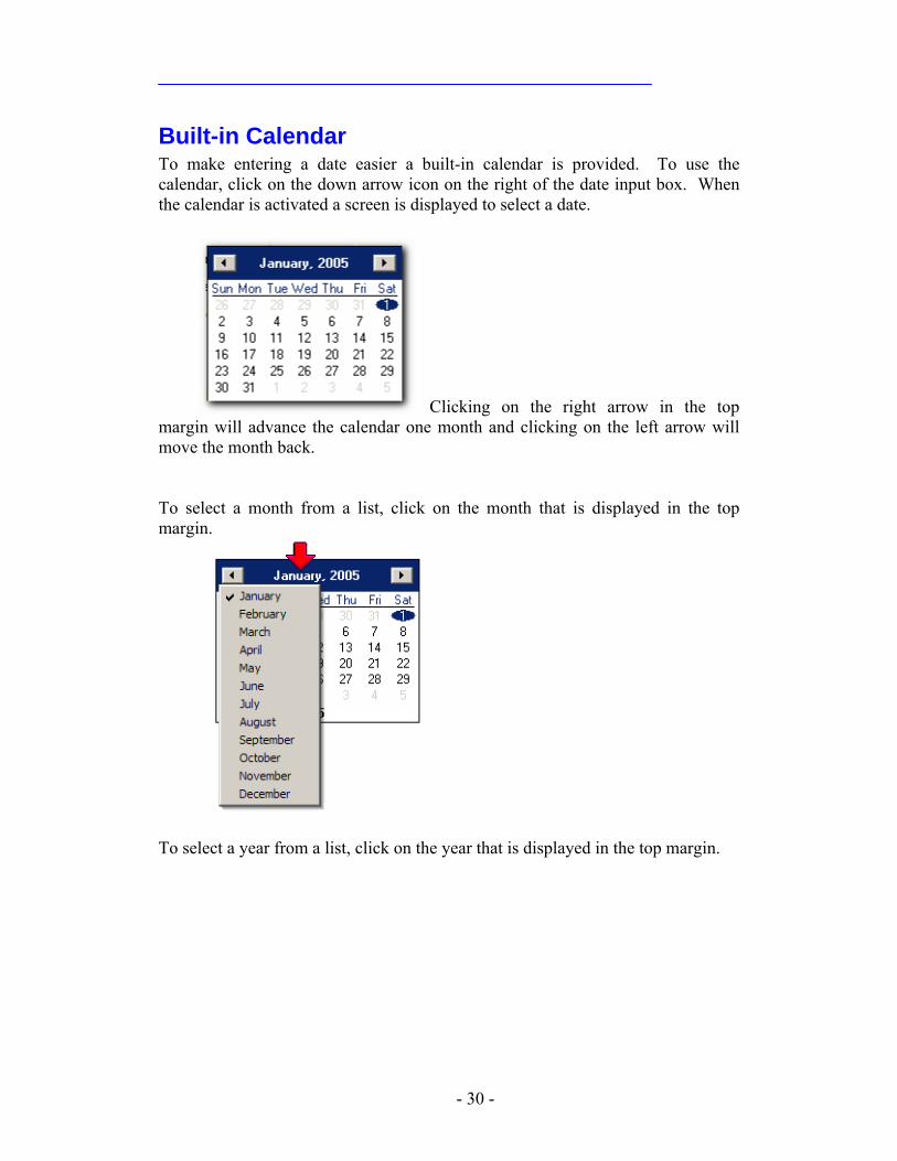
Built-in Calendar To make entering a date easier a built-in calendar is provided. To use the calendar, click on the down arrow icon on the right of the date input box. When the calendar is activated a screen is displayed to select a date.
Clicking on the right arrow in the top month and clicking on the left arrow will
move the month back. margin will advance the calendar one
To select a month from a list, click on the month that is displayed in the top margin.
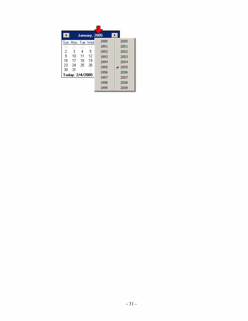
To select a year from a list, click on the year that is displayed in the top margin.
- 30 -
- 31 -
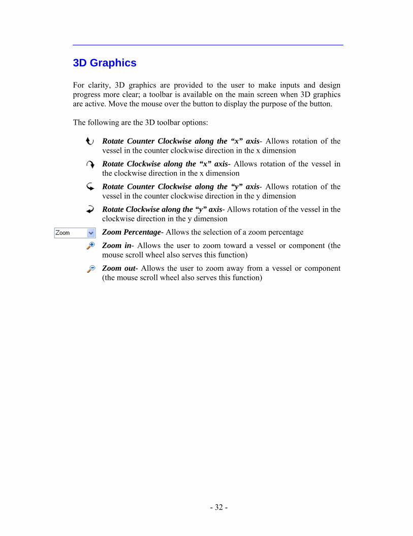
3D Graphics For clarity, 3D graphics are provided to the user to make inputs and design progress more clear; a toolbar is available on the main screen when 3D graphics are active. Move the mouse over the button to display the purpose of the button. The following are the 3D toolbar options:
Rotate Counter Clockwise along the “x” axis- Allows rotation of the vessel in the counter clockwise direction in the x dimension
Rotate Clockwise along the “x” axis- Allows rotation of the vessel in the clockwise direction in the x dimension
Rotate Counter Clockwise along the “y” axis- Allows rotation of the vessel in the counter clockwise direction in the y dimension
Rotate Clockwise along the “y” axis- Allows rotation of the vessel in the clockwise direction in the y dimension
Zoom Percentage- Allows the selection of a zoom percentage
Zoom in- Allows the user to zoom toward a vessel or component (the mouse scroll wheel also serves this function)
Zoom out- Allows the user to zoom away from a vessel or component (the mouse scroll wheel also serves this function)
- 32 -
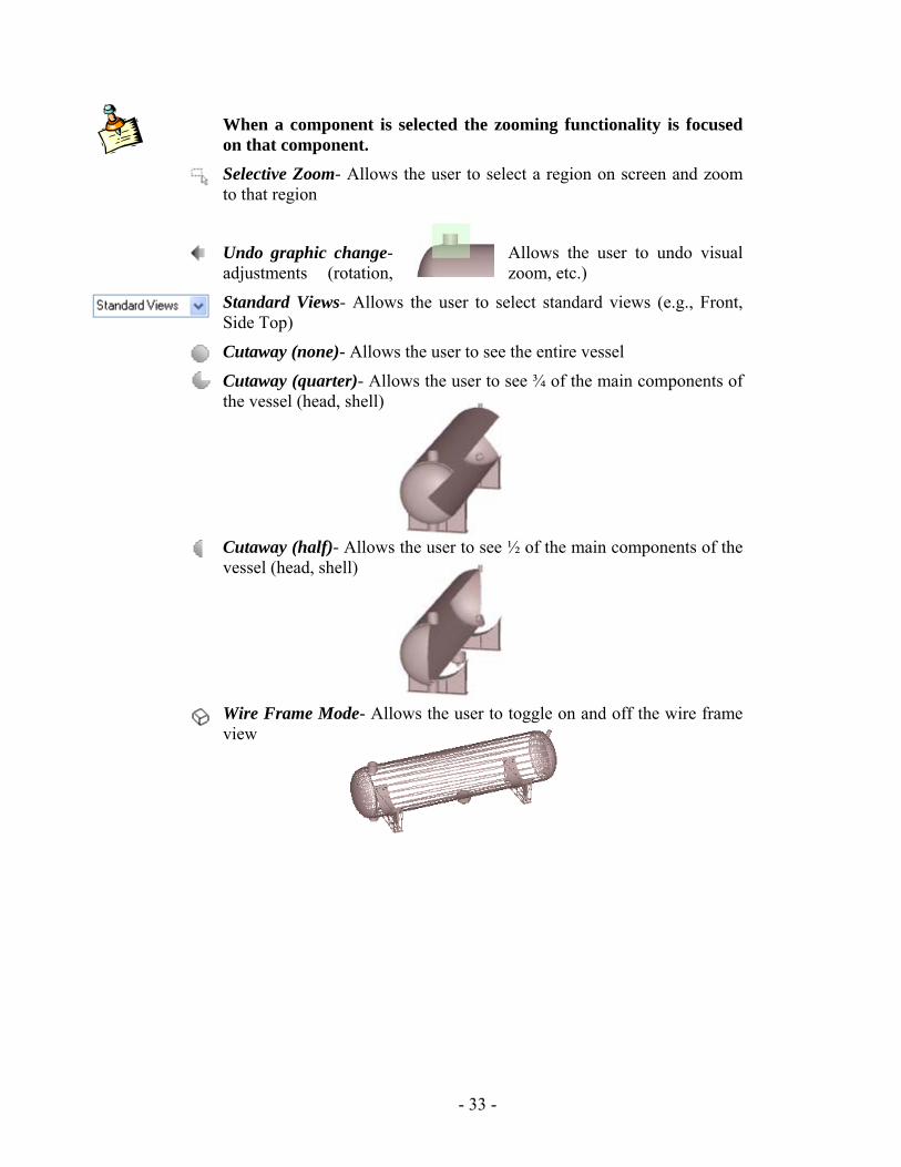
When a component is selected the zooming functionality is focused on that component. Selective Zoom- Allows the user to select a region on screen and zoom to that region
Undo graphic change- Allows the user to undo visual adjustments (rotation, zoom, etc.)
Standard Views- Allows the user to select standard views (e.g., Front, Side Top)
Cutaway (none)- Allows the user to see the entire vessel
Cutaway (quarter)- Allows the user to see ¾ of the main components of the vessel (head, shell)
Cutaway (half)- Allows the user to see ½ of the main components of the vessel (head, shell)
Wire Frame Mode- Allows the user to toggle on and off the wire frame view
- 33 -
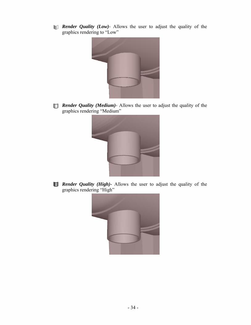
Render Quality (Low)- Allows the user to adjust the quality of the graphics rendering to “Low”
Render Quality (Medium)- Allows the user to adjust the quality of the graphics rendering “Medium”
Render Quality (High)- Allows the user to adjust the quality of the graphics rendering “High”
- 34 -
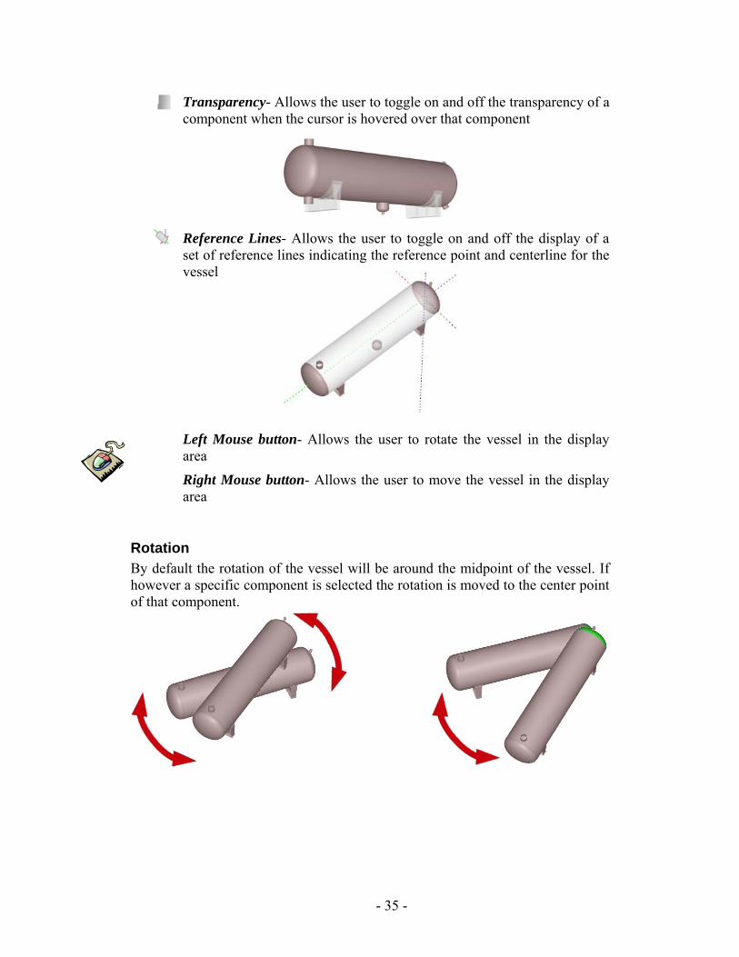
Transparency- Allows the user to toggle on and off the transparency of a component when the cursor is hovered over that component
Reference Lines- Allows the user to toggle on and off the display of a set of reference lines indicating the reference point and centerline for the vessel
Left Mouse button- Allows the user to rotate the vessel in the display area
Right Mouse button- Allows the user to move the vessel in the display area
Rotation By default the rotation of the vessel will be around the midpoint of the vessel. If however a specific component is selected the rotation is moved to the center point of that component.
- 35 -
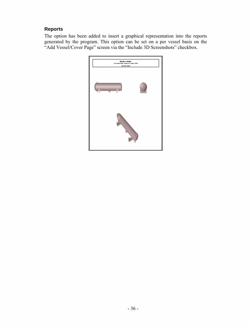
Reports The option has been added to insert a graphical representation into the reports generated by the program. This option can be set on a per vessel basis on the “Add Vessel/Cover Page” screen via the “Include 3D Screenshots” checkbox.
- 36 -
Defaults
Prior to designing the first pressure vessel, you should review and set the Defaults. The program is shipped with preset default values and selections. These settings may not be the desired choices for you. Defaults are used in Advanced Pressure Vessel to make designing pressure vessels quicker and allow your company to standardize your designs. Most Default items can be changed during data entry for a vessel design. To modify or review defaults, click on “Utility” then “Defaults…” from the main menu. The defaults are grouped in notebook tabs to organize information. Help is available by pressing [F1] after you have selected a data field.
4
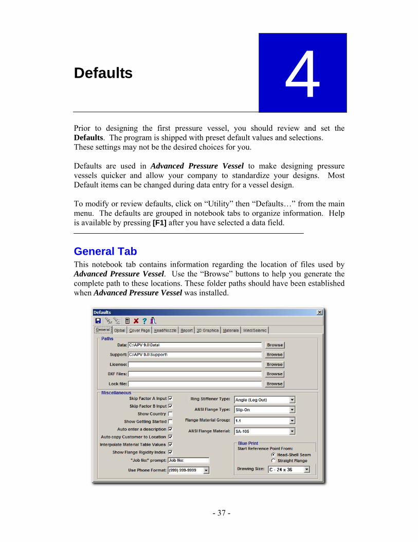
General Tab This notebook tab contains information regarding the location of files used by Advanced Pressure Vessel. Use the “Browse” buttons to help you generate the complete path to these locations. These folder paths should have been established when Advanced Pressure Vessel was installed.
- 37 -
Paths
• Data – The location where the vessel design data is stored. For LAN Pack versions, this must be in a common area of the file server hard drive so that any modifications made to the supporting databases are available to all users.
If multiple sets of data are required, they can be kept in separate folders (subdirectories). For example, two areas of a manufacturing facility could have vessel designs stored in different folders. If data is to be shared with another licensed user of Advanced Pressure Vessel on a network, the data must be stored on the file server.
• Support: – The location of the supporting data. For LAN Pack versions, this must be in a common area of the file server hard drive so that any modifications made to the supporting data are available to all users.
• License: – The location of the License and Authorization information. • DXF Files: - The path used to store the Data Transfer Files (DXF) files
created from the blueprint feature. This can be in the Advanced Pressure Vessel directory or somewhere else on your system or network. This location will be needed when the user imports DXF files into a Computer Aided Drafting (CAD) program.
• Lock File: - The location of the Borland Database Engine (BDE) database control files that protect the database files from being accidentally removed. For LAN Pack version, we recommend this be the shared data folder on the network.
Miscellaneous • Skip Factor A Input – When this box is checked, Advanced Pressure
Vessel will find the “Factor A” value for external pressure calculations and will not allow it to be changed.
When the box is not checked and the Code uses curves to determine the value, you may change the value.
If you change the Factor A value, Advanced Pressure Vessel will no longer update the value for Factor A in the design. If this box is checked after you have changed the value for Factor A, you can no longer modify the field and Advanced Pressure Vessel will not update the value for any changes in the design.
• Skip Factor B Input - When this box is checked, Advanced Pressure Vessel will find the “Factor B” used in the calculations about external pressure effects and you will not be able to change the value.
When the box is not checked, you may change the “Factor B” value.
- 38 -
If you change the Factor B value, Advanced Pressure Vessel will no longer update the value for Factor B in the design. If this box is checked after you have changed the value for Factor B, you can no longer modify the field and Advanced Pressure Vessel will not update the value for any changes in the design.
• Auto Enter a Description – Vessel components have a description that is displayed when browsing. If this default item is checked, then a description, such as “Shell 1” for the first shell section designed, will automatically be entered into the description field. The default description can be overwritten if desired. If a description is not entered and this item is not checked, then it may become more difficult to identify vessel components in the Component Pane (lower left pane).
• Auto Copy Customer to Location – If checked, this will copy the customer information into the location information section of the Vessel form. Information that is copied to “Location” can be overwritten if desired.
• Interpolate Material Table Values – Advanced Pressure Vessel will interpolate temperature and stress values from information in the material tables if this is checked. If unchecked, the next smaller value from the material tables for these parameters will be used.
• Show Flange Rigidity Index – When checked, the flange rigidity values are shown on the flange design screen and on flange reports.
• Job Number prompt – Some companies use an identifier other than “Job Number” (i.e., “Work Order”, “Sales Order”, etc.) to keep track of vessel designs. This prompt can be changed to another prompt.
• Ring Stiffener Type, ANSI Flange Type, Flange Material Group, ANSI Flange Material – Select the item most often used. These may be changed during data input.
Blue Print Drawing Size – This field has a drop-down list of drawing sizes. You should select the size that is used most often. When the drawing size selected is different than the paper size in your printer, the proportions may be different than expected. Advanced Pressure Vessel will force the drawing to fit on the paper size reported by Windows.
- 39 -
Global Tab This tab contains important defaults that should be reviewed. When a vessel is designed, these parameters are inserted into their appropriate fields. You can change most of these items while designing a vessel.
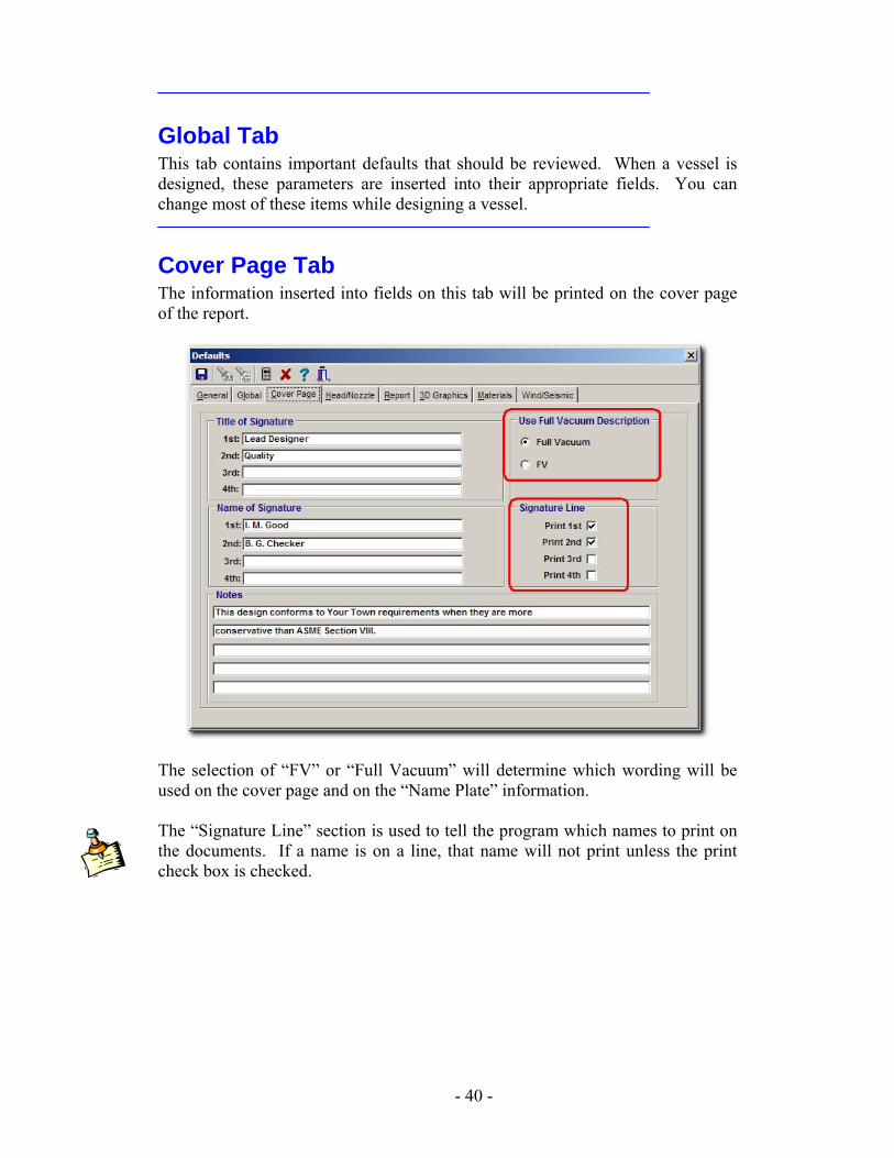
Cover Page Tab The information inserted into fields on this tab will be printed on the cover page of the report.
The selection of “FV” or “Full Vacuum” will determine which wording will be used on the cover page and on the “Name Plate” information. The “Signature Line” section is used to tell the program which names to print on the documents. If a name is on a line, that name will not print unless the print check box is checked.
- 40 -
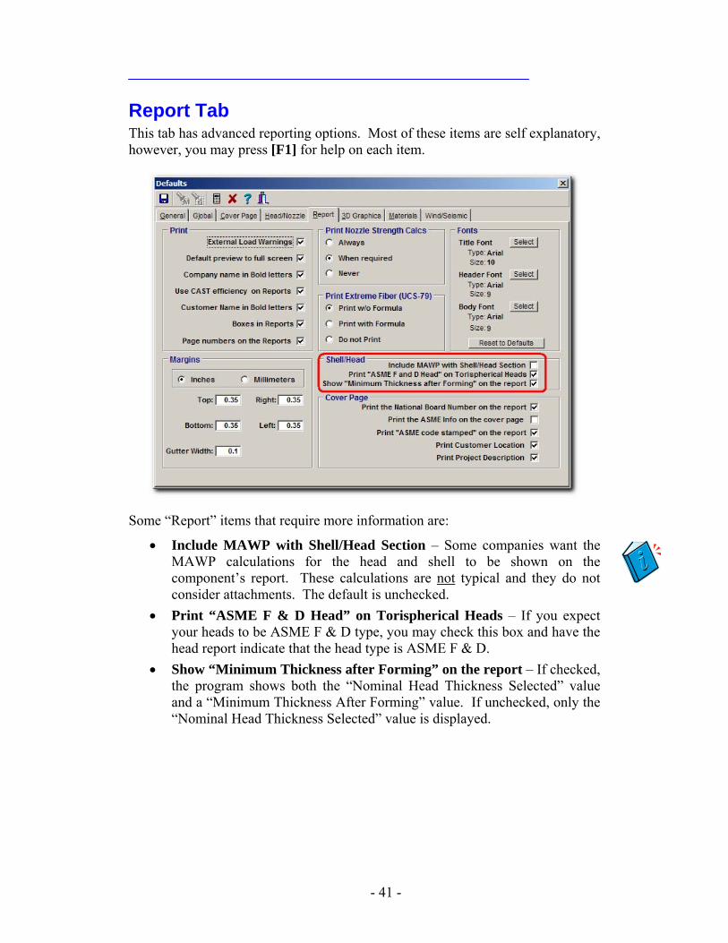
Report Tab This tab has advanced reporting options. Most of these items are self explanatory, however, you may press [F1] for help on each item.
Some “Report” items that require more information are:
• Include MAWP with Shell/Head Section – Some companies want the MAWP calculations for the head and shell to be shown on the component’s report. These calculations are not typical and they do not consider attachments. The default is unchecked.
• Print “ASME F & D Head” on Torispherical Heads – If you expect your heads to be ASME F & D type, you may check this box and have the head report indicate that the head type is ASME F & D.
• Show “Minimum Thickness after Forming” on the report – If checked, the program shows both the “Nominal Head Thickness Selected” value and a “Minimum Thickness After Forming” value. If unchecked, only the “Nominal Head Thickness Selected” value is displayed.
- 41 -
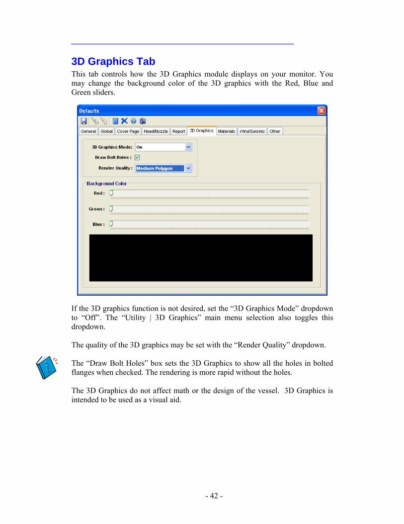
3D Graphics Tab This tab controls how the 3D Graphics module displays on your monitor. You may change the background color of the 3D graphics with the Red, Blue and Green sliders.
If the 3D graphics function is not desired, set the “3D Graphics Mode” dropdown to “Off”. The “Utility | 3D Graphics” main menu selection also toggles this dropdown. The quality of the 3D graphics may be set with the “Render Quality” dropdown. The “Draw Bolt Holes” box sets the 3D Graphics to show all the holes in bolted flanges when checked. The rendering is more rapid without the holes. The 3D Graphics do not affect math or the design of the vessel. 3D Graphics is intended to be used as a visual aid.
- 42 -
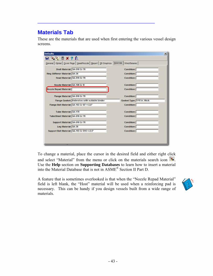
Materials Tab These are the materials that are used when first entering the various vessel design screens.
To change a material, place the cursor in the desired field and either right click and select “Material” from the menu or click on the materials search icon . Use the Help section on Supporting Databases to learn how to insert a material into the Material Database that is not in ASME® Section II Part D. A feature that is sometimes overlooked is that when the “Nozzle Repad Material” field is left blank, the “Host” material will be used when a reinforcing pad is necessary. This can be handy if you design vessels built from a wide range of materials.
- 43 -
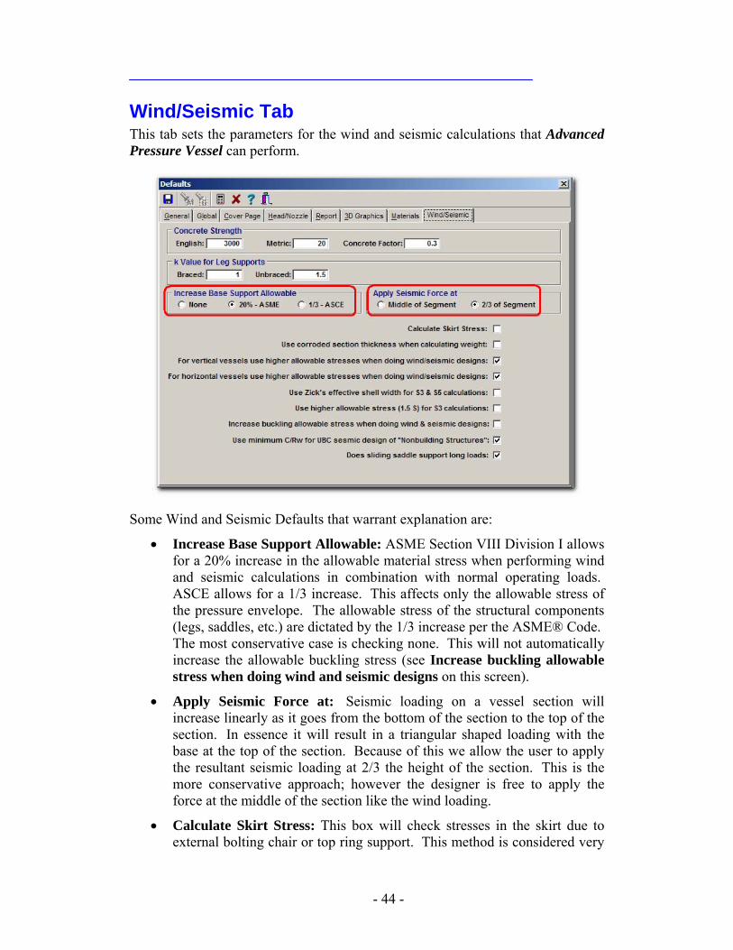
Wind/Seismic Tab This tab sets the parameters for the wind and seismic calculations that Advanced Pressure Vessel can perform.
Some Wind and Seismic Defaults that warrant explanation are:
• Increase Base Support Allowable: ASME Section VIII Division I allows for a 20% increase in the allowable material stress when performing wind and seismic calculations in combination with normal operating loads. ASCE allows for a 1/3 increase. This affects only the allowable stress of the pressure envelope. The allowable stress of the structural components (legs, saddles, etc.) are dictated by the 1/3 increase per the ASME® Code. The most conservative case is checking none. This will not automatically increase the allowable buckling stress (see Increase buckling allowable stress when doing wind and seismic designs on this screen).
• Apply Seismic Force at: Seismic loading on a vessel section will increase linearly as it goes from the bottom of the section to the top of the section. In essence it will result in a triangular shaped loading with the base at the top of the section. Because of this we allow the user to apply the resultant seismic loading at 2/3 the height of the section. This is the more conservative approach; however the designer is free to apply the force at the middle of the section like the wind loading.
• Calculate Skirt Stress: This box will check stresses in the skirt due to external bolting chair or top ring support. This method is considered very
- 44 -
conservative for most designs, though. See the help for further guidance as to whether this box should be checked or not.
• Use corroded section thickness when calculating weight: Leaving this unchecked will perform the most conservative vessel weight calculation using the uncorroded condition. This heavier weight will be used in the support calculations such as saddles, legs, and skirts.
• For vertical vessels use higher allowable stresses when doing wind/seismic designs: Checking this box will use the increased allowable stress for the support calculations (wind/seismic) for vertical vessels. The increased allowable stress used is chosen in the field Increase Base Support Allowable on this screen. This will not automatically increase the allowable buckling stress (see Increase buckling allowable stress when doing wind and seismic designs on this screen).
• For horizontal vessels use higher allowable stresses when doing wind/seismic designs: Checking this box will use the increased allowable stress for the support calculations (wind/seismic) for horizontal vessels. The increased allowable stress used is chosen in the field Increase Base Support Allowable on this screen. This will not automatically increase the allowable buckling stress (see Increase buckling allowable stress when doing wind and seismic designs on this screen).
• Use Zick’s effective shell width for S3 and S5 calculations: Zick’s paper uses an effective width of the shell wall that has been considered too conservative by many current references. These references allow for more of the shell wall to be used to lower these stresses. Checking this box will lower the effective width used and increase the calculated stresses.
• Use higher allowable stress (1.5 S) for S3 Calculations: Zick’s paper suggests an allowable stress for stress S3 be 1.5S. More recent references suggest that the allowable stress be reduced to 1.25S. Leaving this unchecked is more conservative.
• Increase buckling allowable stress when doing wind and seismic designs: Even though the code allows for a 20% increase in stress when performing wind and seismic calculations in combinations with normal operating loads, it is not recommended that this be allowed for buckling phenomenon. It is HIGHLY recommended that you do not check this box.
• Use minimum C/Rw for UBC seismic design of “Nonbuilding Structures”: If this box is checked, the minimum C/Rw value specified by the UBC codes will be used even if the calculated value is lower. This does not apply to all codes.
• Does sliding saddles support long loads: If this box is not checked NONE of the longitudinal loadings will be carried by the sliding saddle; one saddle will have to carry all of them. The weight and transverse loadings will still be distributed between both saddles if this is not checked.
- 45 -

- 46 -
Quick Start
Program defaults should be set prior to designing vessels. See Chapter 3 for conventions and Chapter 4 for information about setting defaults.
Introduction A vessel design must start with the “Add Vessel” form. After general vessel information is entered, specific vessel components may be designed. Some components, such as nozzles or ring stiffeners, require “hosts” or a complementary component. Their calculations can only be done after the host component is designed. When entering dimensions, the nominal value (thickness without consideration for corrosion allowance or thinning) should be entered. The program has been designed to allow for corrosion allowance and thin out in all calculations where required by Code.
5
Typical Steps for Designing a Vessel A typical sequence to design a vessel would be as follows:
1) Vessel information. 2) Lower or right head. 3) Shell and Conical sections starting from the lower (right) head. 4) Upper or left head. 5) Ring Stiffener (requires a shell). 6) Cone to cylinder reinforcement (requires a cone or conical head). 7) Nozzles (requires a shell, head, cone, nozzle, or blind flange). 8) Flanges. 9) Attachment and loadings 10) WRC-107 analysis (if necessary). 11) Supports (If the appropriate module is licensed).
This outline is only one approach to designing a vessel. You may vary from this sequence except for those parts that must have a host component.
- 47 -
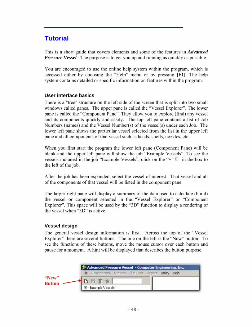
Tutorial This is a short guide that covers elements and some of the features in Advanced Pressure Vessel. The purpose is to get you up and running as quickly as possible. You are encouraged to use the online help system within the program, which is accessed either by choosing the “Help” menu or by pressing [F1]. The help system contains detailed or specific information on features within the program.
User interface basics There is a "tree" structure on the left side of the screen that is split into two small windows called panes. The upper pane is called the “Vessel Explorer”. The lower pane is called the “Component Pane”. They allow you to explore (find) any vessel and its components quickly and easily. The top left pane contains a list of Job Numbers (names) and the Vessel Number(s) of the vessel(s) under each Job. The lower left pane shows the particular vessel selected from the list in the upper left pane and all components of that vessel such as heads, shells, nozzles, etc. When you first start the program the lower left pane (Component Pane) will be blank and the upper left pane will show the job “Example Vessels”. To see the vessels included in the job “Example Vessels”, click on the “+” in the box to the left of the job. After the job has been expanded, select the vessel of interest. That vessel and all of the components of that vessel will be listed in the component pane. The larger right pane will display a summary of the data used to calculate (build) the vessel or component selected in the “Vessel Explorer” or “Component Explorer”. This space will be used by the “3D” function to display a rendering of the vessel when “3D” is active.
Vessel design The general vessel design information is first. Across the top of the “Vessel Explorer” there are several buttons. The one on the left is the “New” button. To see the functions of these buttons, move the mouse cursor over each button and pause for a moment. A hint will be displayed that describes the button purpose.
“New” Button
- 48 -
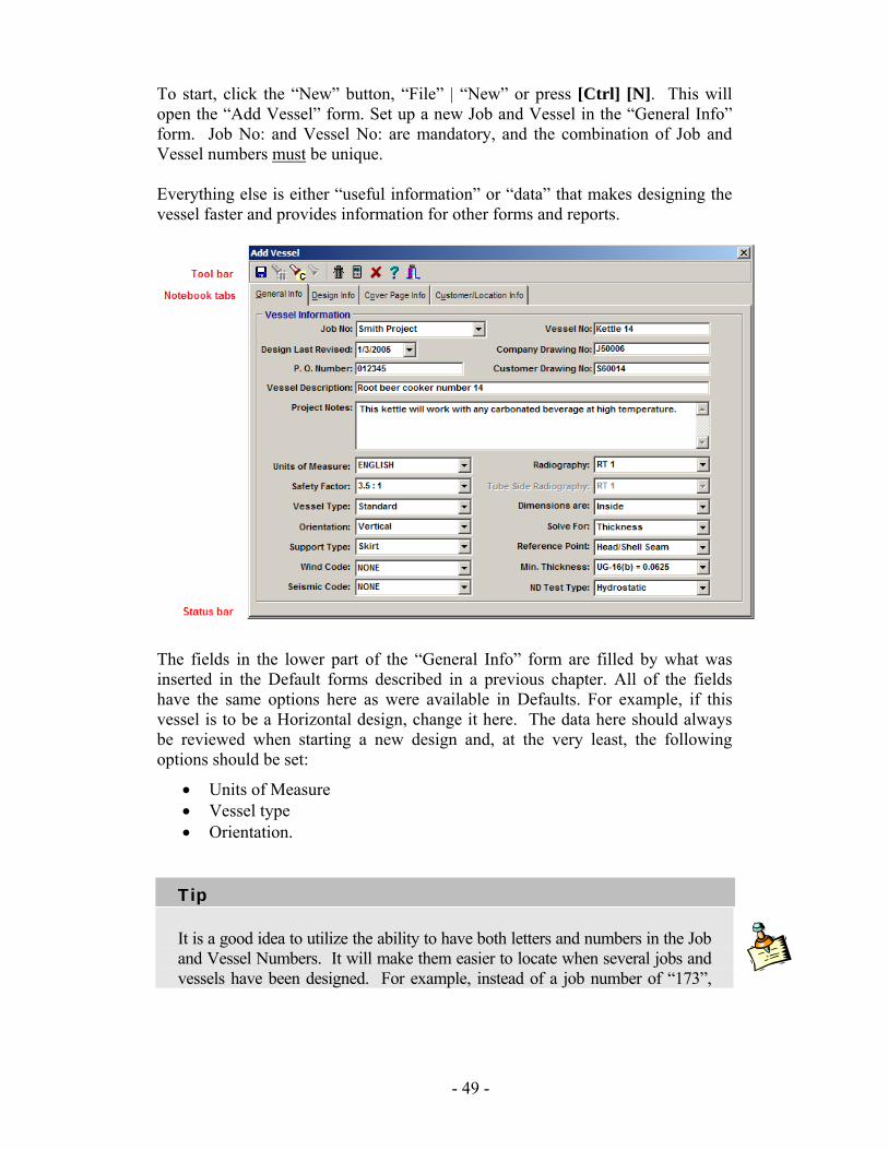
To start, click the “New” button, “File” | “New” or press [Ctrl] [N]. This will open the “Add Vessel” form. Set up a new Job and Vessel in the “General Info” form. Job No: and Vessel No: are mandatory, and the combination of Job and Vessel numbers must be unique. Everything else is either “useful information” or “data” that makes designing the vessel faster and provides information for other forms and reports.
The fields in the lower part of the “General Info” form are filled by what was inserted in the Default forms described in a previous chapter. All of the fields have the same options here as were available in Defaults. For example, if this vessel is to be a Horizontal design, change it here. The data here should always be reviewed when starting a new design and, at the very least, the following options should be set:
• Units of Measure • Vessel type • Orientation.
Tip
It is a good idea to utilize the ability to have both letters and numbers in the Job and Vessel Numbers. It will make them easier to locate when several jobs and vessels have been designed. For example, instead of a job number of “173”,
- 49 -
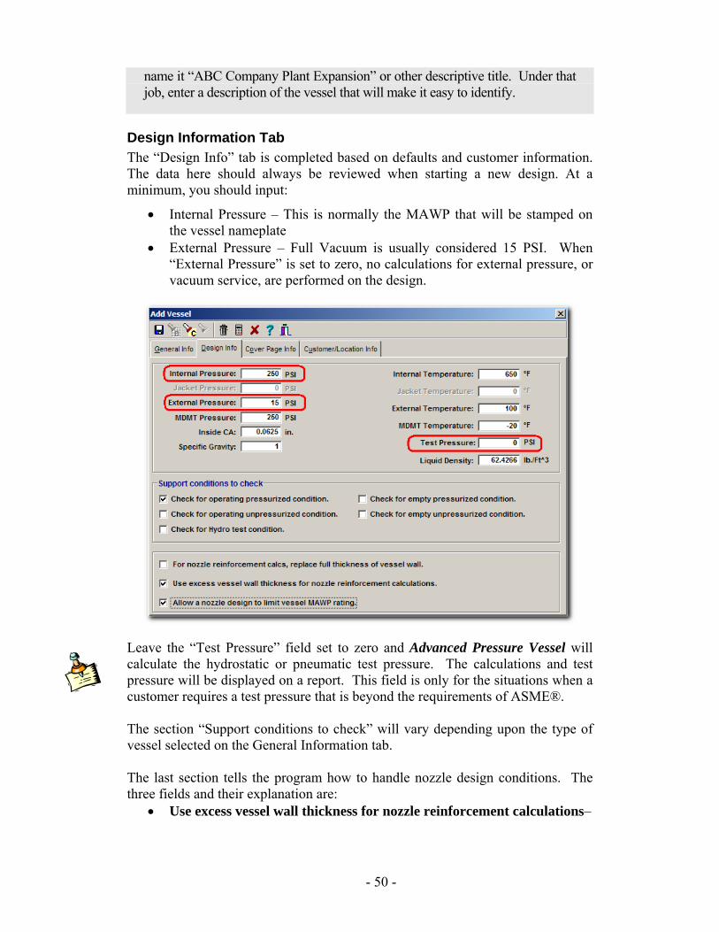
name it “ABC Company Plant Expansion” or other descriptive title. Under that job, enter a description of the vessel that will make it easy to identify.
Design Information Tab The “Design Info” tab is completed based on defaults and customer information. The data here should always be reviewed when starting a new design. At a minimum, you should input:
• Internal Pressure – This is normally the MAWP that will be stamped on the vessel nameplate
• External Pressure – Full Vacuum is usually considered 15 PSI. When “External Pressure” is set to zero, no calculations for external pressure, or vacuum service, are performed on the design.
Leave the “Test Pressure” field set to zero and Advanced Pressure Vessel will calculate the hydrostatic or pneumatic test pressure. The calculations and test pressure will be displayed on a report. This field is only for the situations when a customer requires a test pressure that is beyond the requirements of ASME®. The section “Support conditions to check” will vary depending upon the type of vessel selected on the General Information tab. The last section tells the program how to handle nozzle design conditions. The three fields and their explanation are:
• Use excess vessel wall thickness for nozzle reinforcement calculations–
- 50 -
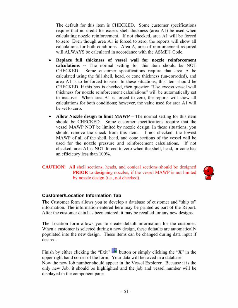
The default for this item is CHECKED. Some customer specifications require that no credit for excess shell thickness (area A1) be used when calculating nozzle reinforcement. If not checked, area A1 will be forced to zero. Even though area A1 is forced to zero, the reports will show all calculations for both conditions. Area A, area of reinforcement required will ALWAYS be calculated in accordance with the ASME® Code.
• Replace full thickness of vessel wall for nozzle reinforcement calculations -- The normal setting for this item should be NOT CHECKED. Some customer specifications require that area A be calculated using the full shell, head, or cone thickness (un-corroded), and area A1 is to be forced to zero. In these situations, this item should be CHECKED. If this box is checked, then question “Use excess vessel wall thickness for nozzle reinforcement calculations” will be automatically set to inactive. When area A1 is forced to zero, the reports will show all calculations for both conditions; however, the value used for area A1 will be set to zero.
• Allow Nozzle design to limit MAWP – The normal setting for this item should be CHECKED. Some customer specifications require that the vessel MAWP NOT be limited by nozzle design. In these situations, you should remove the check from this item. If not checked, the lowest MAWP of all of the shell, head, and cone sections of the vessel will be used for the nozzle pressure and reinforcement calculations. If not checked, area A1 is NOT forced to zero when the shell, head, or cone has an efficiency less than 100%.
CAUTION! All shell sections, heads, and conical sections should be designed PRIOR to designing nozzles, if the vessel MAWP is not limited by nozzle design (i.e., not checked).
Customer/Location Information Tab The Customer form allows you to develop a database of customer and “ship to” information. The information entered here may be printed as part of the Report. After the customer data has been entered, it may be recalled for any new designs. The Location form allows you to create default information for the customer. When a customer is selected during a new design, these defaults are automatically populated into the new design. These items can be changed during data input if desired. Finish by either clicking the “Exit” button or simply clicking the “X” in the upper right hand corner of the form. Your data will be saved in a database. Now the new Job number should appear in the Vessel Explorer. Because it is the only new Job, it should be highlighted and the job and vessel number will be displayed in the component pane.
- 51 -
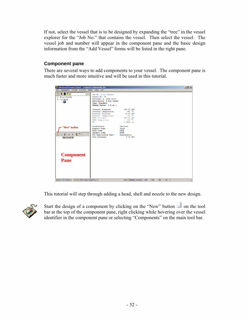
If not, select the vessel that is to be designed by expanding the “tree” in the vessel explorer for the “Job No:” that contains the vessel. Then select the vessel. The vessel job and number will appear in the component pane and the basic design information from the “Add Vessel” forms will be listed in the right pane.
Component pane There are several ways to add components to your vessel. The component pane is much faster and more intuitive and will be used in this tutorial.
Component
Pane This tutorial will step through adding a head, shell and nozzle to the new design. Start the design of a component by clicking on the “New” button on the tool bar at the top of the component pane, right clicking while hovering over the vessel identifier in the component pane or selecting “Components” on the main tool bar.
- 52 -
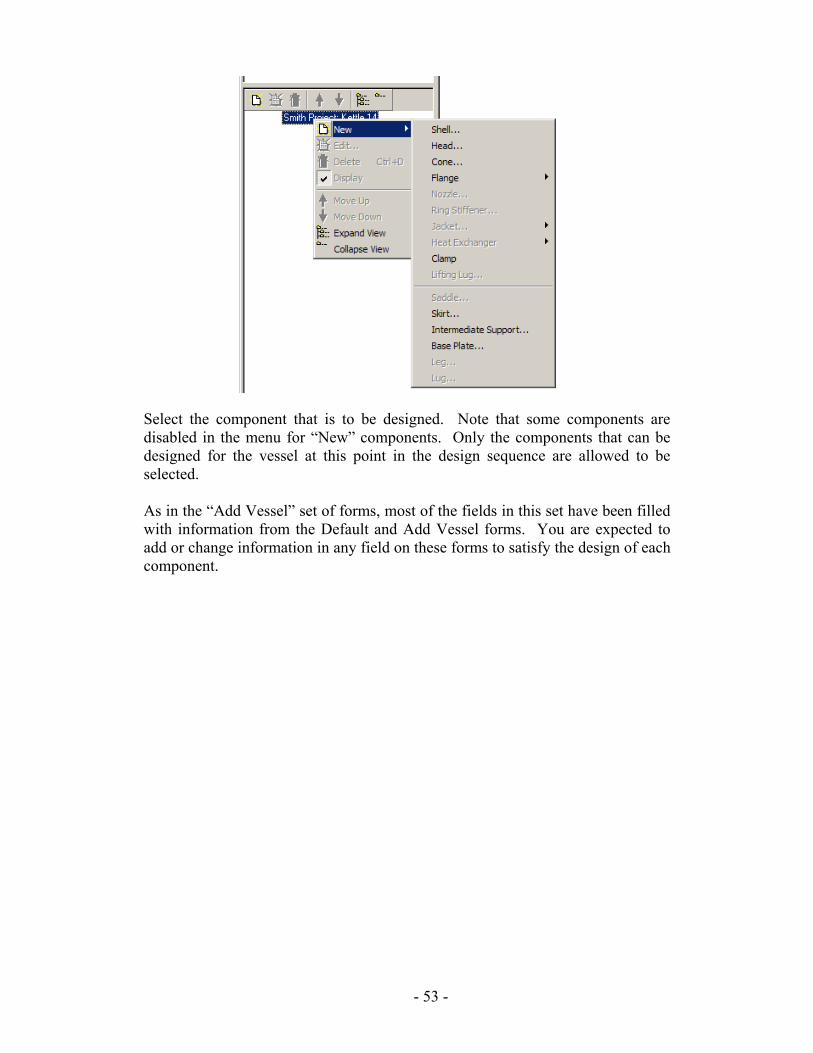
Select the component that is to be designed. Note that some components are disabled in the menu for “New” components. Only the components that can be designed for the vessel at this point in the design sequence are allowed to be selected. As in the “Add Vessel” set of forms, most of the fields in this set have been filled with information from the Default and Add Vessel forms. You are expected to add or change information in any field on these forms to satisfy the design of each component.
- 53 -
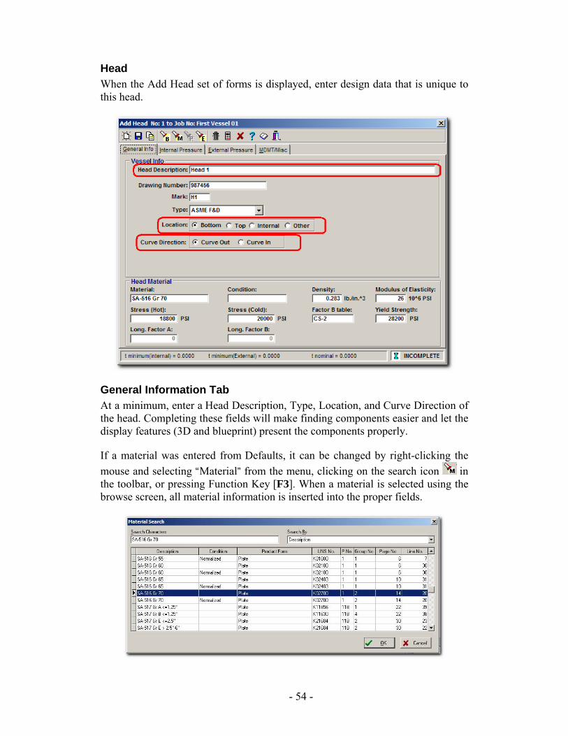
Head When the Add Head set of forms is displayed, enter design data that is unique to this head.
General Information Tab At a minimum, enter a Head Description, Type, Location, and Curve Direction of the head. Completing these fields will make finding components easier and let the display features (3D and blueprint) present the components properly. If a material was entered from Defaults, it can be changed by right-clicking the mouse and selecting “Material” from the menu, clicking on the search icon in the toolbar, or pressing Function Key [F3]. When a material is selected using the browse screen, all material information is inserted into the proper fields.
- 54 -
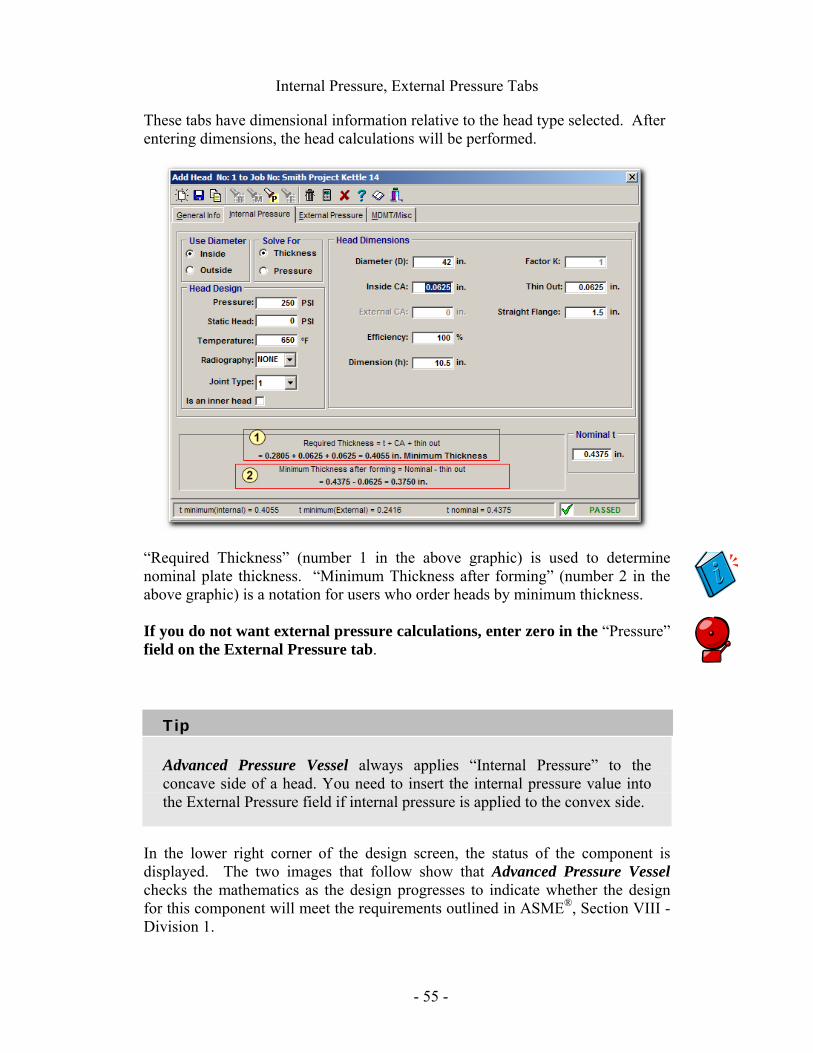
Internal Pressure, External Pressure Tabs
These tabs have dimensional information relative to the head type selected. After entering dimensions, the head calculations will be performed.
“Required Thickness” (number 1 in the above graphic) is used to determine nominal plate thickness. “Minimum Thickness after forming” (number 2 in the above graphic) is a notation for users who order heads by minimum thickness. If you do not want external pressure calculations, enter zero in the “Pressure” field on the External Pressure tab.
Tip
Advanced Pressure Vessel always applies “Internal Pressure” to the concave side of a head. You need to insert the internal pressure value into the External Pressure field if internal pressure is applied to the convex side.
In the lower right corner of the design screen, the status of the component is displayed. The two images that follow show that Advanced Pressure Vessel checks the mathematics as the design progresses to indicate whether the design for this component will meet the requirements outlined in ASME®, Section VIII - Division 1.
- 55 -
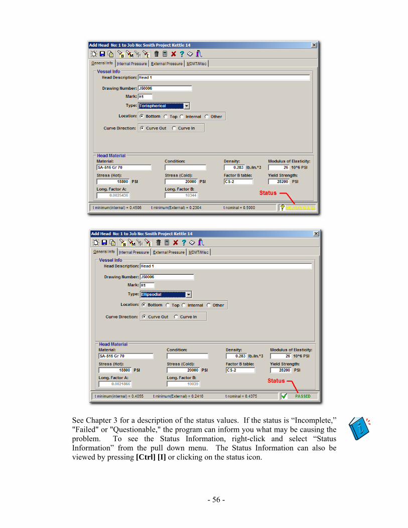
See Chapter 3 for a description of the status values. If the status is “Incomplete,” "Failed" or "Questionable," the program can inform you what may be causing the problem. To see the Status Information, right-click and select “Status Information” from the pull down menu. The Status Information can also be viewed by pressing [Ctrl] [I] or clicking on the status icon.
- 56 -

Also look for any red or yellow text on the data input form. This is used to draw your attention to the possible item that is failing, questionable, or out of range.
- 57 -
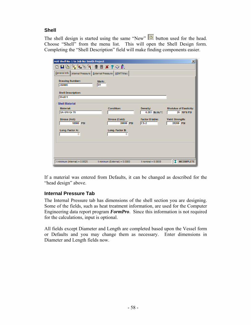
Shell The shell design is started using the same “New” button used for the head. Choose “Shell” from the menu list. This will open the Shell Design form. Completing the “Shell Description” field will make finding components easier.
If a material was entered from Defaults, it can be changed as described for the “head design” above.
Internal Pressure Tab The Internal Pressure tab has dimensions of the shell section you are designing. Some of the fields, such as heat treatment information, are used for the Computer Engineering data report program FormPro. Since this information is not required for the calculations, input is optional. All fields except Diameter and Length are completed based upon the Vessel form or Defaults and you may change them as necessary. Enter dimensions in Diameter and Length fields now.
- 58 -
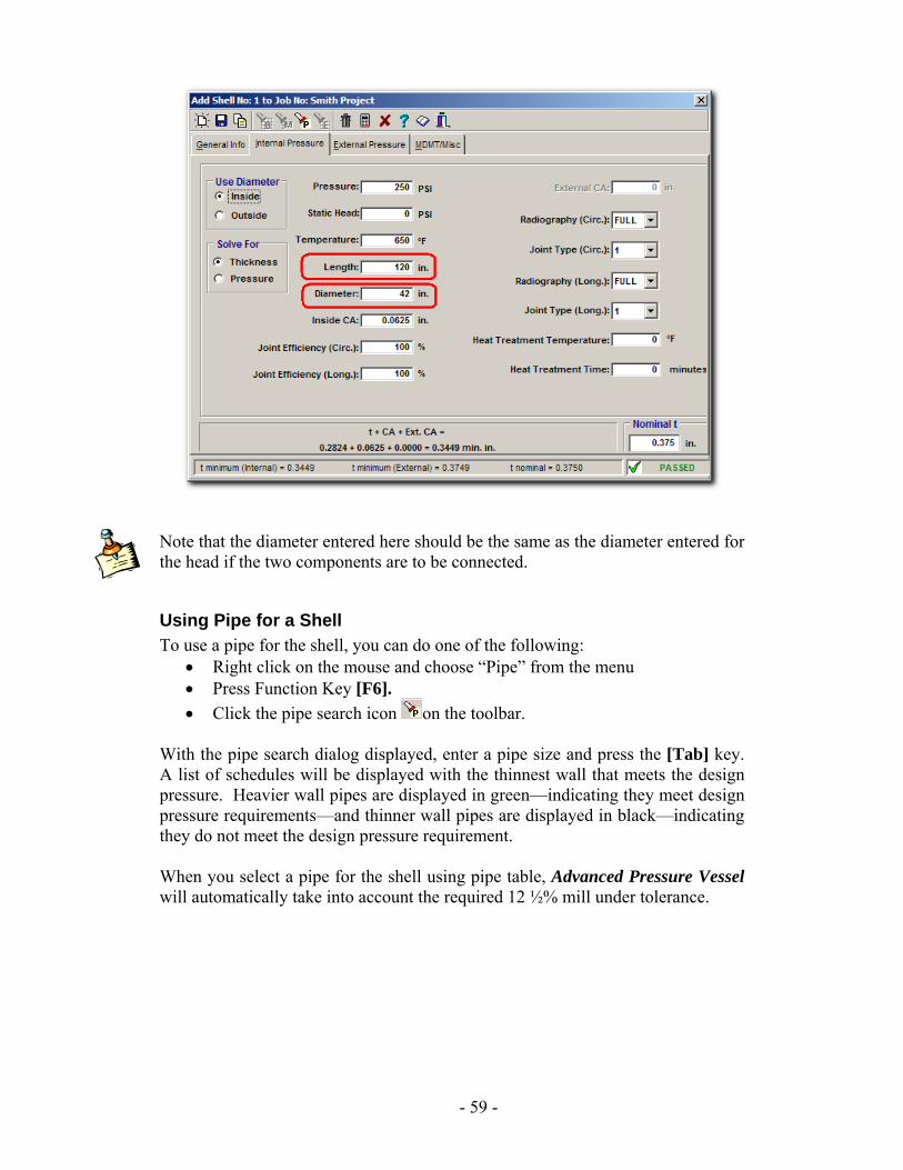
Note that the diameter entered here should be the same as the diameter entered for the head if the two components are to be connected.
Using Pipe for a Shell To use a pipe for the shell, you can do one of the following:
• Right click on the mouse and choose “Pipe” from the menu • Press Function Key [F6]. • Click the pipe search icon on the toolbar.
With the pipe search dialog displayed, enter a pipe size and press the [Tab] key. A list of schedules will be displayed with the thinnest wall that meets the design pressure. Heavier wall pipes are displayed in green—indicating they meet design pressure requirements—and thinner wall pipes are displayed in black—indicating they do not meet the design pressure requirement. When you select a pipe for the shell using pipe table, Advanced Pressure Vessel will automatically take into account the required 12 ½% mill under tolerance.
- 59 -
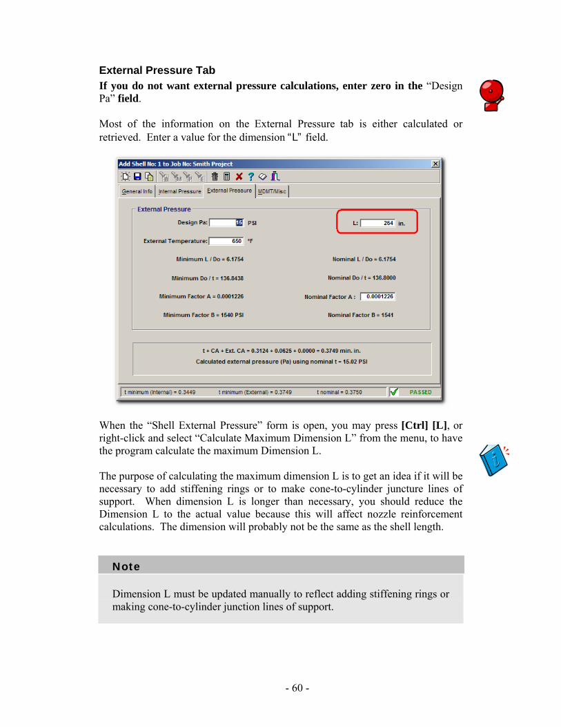
External Pressure Tab If you do not want external pressure calculations, enter zero in the “Design Pa” field. Most of the information on the External Pressure tab is either calculated or retrieved. Enter a value for the dimension “L” field.
When the “Shell External Pressure” form is open, you may press [Ctrl] [L], or right-click and select “Calculate Maximum Dimension L” from the menu, to have the program calculate the maximum Dimension L. The purpose of calculating the maximum dimension L is to get an idea if it will be necessary to add stiffening rings or to make cone-to-cylinder juncture lines of support. When dimension L is longer than necessary, you should reduce the Dimension L to the actual value because this will affect nozzle reinforcement calculations. The dimension will probably not be the same as the shell length.
Note
Dimension L must be updated manually to reflect adding stiffening rings or making cone-to-cylinder junction lines of support.
- 60 -

Once the shell design is completed, choose Exit or close the window. The shell design will automatically be saved.
- 61 -
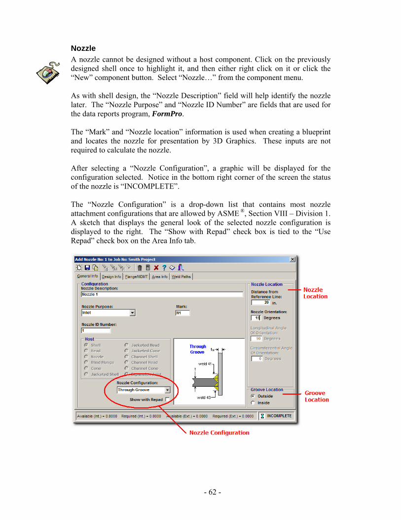
Nozzle A nozzle cannot be designed without a host component. Click on the previously designed shell once to highlight it, and then either right click on it or click the “New” component button. Select “Nozzle…” from the component menu. As with shell design, the “Nozzle Description” field will help identify the nozzle later. The “Nozzle Purpose” and “Nozzle ID Number” are fields that are used for the data reports program, FormPro. The “Mark” and “Nozzle location” information is used when creating a blueprint and locates the nozzle for presentation by 3D Graphics. These inputs are not required to calculate the nozzle. After selecting a “Nozzle Configuration”, a graphic will be displayed for the configuration selected. Notice in the bottom right corner of the screen the status of the nozzle is “INCOMPLETE”. The “Nozzle Configuration” is a drop-down list that contains most nozzle attachment configurations that are allowed by ASME ®, Section VIII – Division 1. A sketch that displays the general look of the selected nozzle configuration is displayed to the right. The “Show with Repad” check box is tied to the “Use Repad” check box on the Area Info tab.
- 62 -

The “Groove Location” area is for those attachments that include a groove weld. You have the choice to have the groove to be welded from the outside or inside of the vessel.
- 63 -
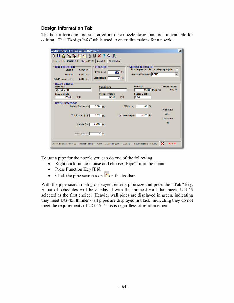
Design Information Tab The host information is transferred into the nozzle design and is not available for editing. The “Design Info” tab is used to enter dimensions for a nozzle.
To use a pipe for the nozzle you can do one of the following: • Right click on the mouse and choose “Pipe” from the menu • Press Function Key [F6]. • Click the pipe search icon on the toolbar.
With the pipe search dialog displayed, enter a pipe size and press the “Tab” key. A list of schedules will be displayed with the thinnest wall that meets UG-45 selected as the first choice. Heavier wall pipes are displayed in green, indicating they meet UG-45; thinner wall pipes are displayed in black, indicating they do not meet the requirements of UG-45. This is regardless of reinforcement.
- 64 -
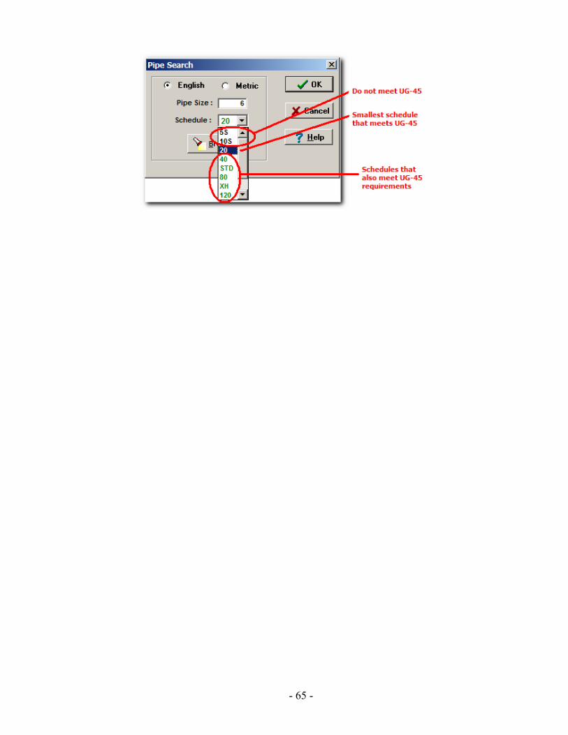
- 65 -
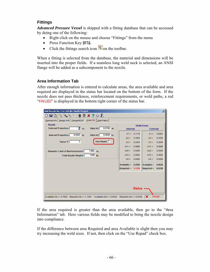
Fittings Advanced Pressure Vessel is shipped with a fitting database that can be accessed by doing one of the following:
• Right click on the mouse and choose “Fittings” from the menu • Press Function Key [F5]. • Click the fittings search icon on the toolbar.
When a fitting is selected from the database, the material and dimensions will be inserted into the proper fields. If a seamless long weld neck is selected, an ANSI flange will be added as a subcomponent to the nozzle.
Area Information Tab After enough information is entered to calculate areas, the area available and area required are displayed in the status bar located on the bottom of the form. If the nozzle does not pass thickness, reinforcement requirements, or weld paths, a red “FAILED” is displayed in the bottom right corner of the status bar.
If the area required is greater than the area available, then go to the “Area Information” tab. Here various fields may be modified to bring the nozzle design into compliance. If the difference between area Required and area Available is slight then you may try increasing the weld sizes. If not, then click on the “Use Repad” check box.
- 66 -
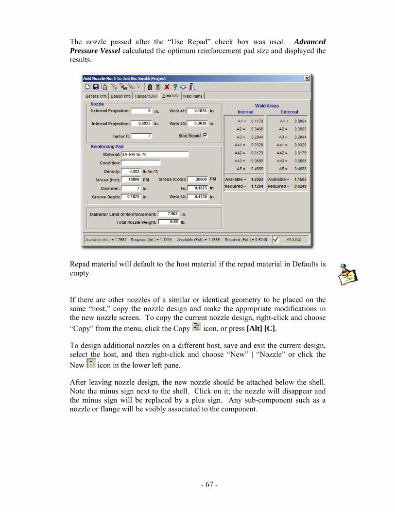
The nozzle passed after the “Use Repad” check box was used. Advanced Pressure Vessel calculated the optimum reinforcement pad size and displayed the results.
Repad material will default to the host material if the repad material in Defaults is empty. If there are other nozzles of a similar or identical geometry to be placed on the same “host,” copy the nozzle design and make the appropriate modifications in the new nozzle screen. To copy the current nozzle design, right-click and choose “Copy” from the menu, click the Copy icon, or press [Alt] [C]. To design additional nozzles on a different host, save and exit the current design, select the host, and then right-click and choose “New” | “Nozzle” or click the New icon in the lower left pane. After leaving nozzle design, the new nozzle should be attached below the shell. Note the minus sign next to the shell. Click on it; the nozzle will disappear and the minus sign will be replaced by a plus sign. Any sub-component such as a nozzle or flange will be visibly associated to the component.
- 67 -
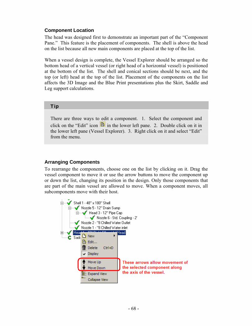
Component Location The head was designed first to demonstrate an important part of the “Component Pane.” This feature is the placement of components. The shell is above the head on the list because all new main components are placed at the top of the list. When a vessel design is complete, the Vessel Explorer should be arranged so the bottom head of a vertical vessel (or right head of a horizontal vessel) is positioned at the bottom of the list. The shell and conical sections should be next, and the top (or left) head at the top of the list. Placement of the components on the list affects the 3D Image and the Blue Print presentations plus the Skirt, Saddle and Leg support calculations.
Tip
There are three ways to edit a component. 1. Select the component and click on the “Edit” icon in the lower left pane. 2. Double click on it in the lower left pane (Vessel Explorer). 3. Right click on it and select “Edit” from the menu.
Arranging Components To rearrange the components, choose one on the list by clicking on it. Drag the vessel component to move it or use the arrow buttons to move the component up or down the list, changing its position in the design. Only those components that are part of the main vessel are allowed to move. When a component moves, all subcomponents move with their host.
- 68 -
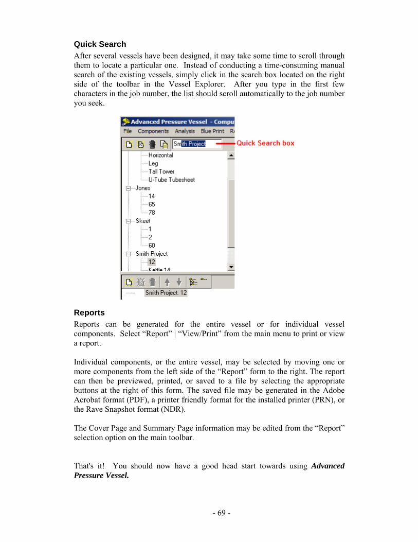
Quick Search After several vessels have been designed, it may take some time to scroll through them to locate a particular one. Instead of conducting a time-consuming manual search of the existing vessels, simply click in the search box located on the right side of the toolbar in the Vessel Explorer. After you type in the first few characters in the job number, the list should scroll automatically to the job number you seek.
Reports Reports can be generated for the entire vessel or for individual vessel components. Select “Report” | “View/Print” from the main menu to print or view a report. Individual components, or the entire vessel, may be selected by moving one or more components from the left side of the “Report” form to the right. The report can then be previewed, printed, or saved to a file by selecting the appropriate buttons at the right of this form. The saved file may be generated in the Adobe Acrobat format (PDF), a printer friendly format for the installed printer (PRN), or the Rave Snapshot format (NDR). The Cover Page and Summary Page information may be edited from the “Report” selection option on the main toolbar. That's it! You should now have a good head start towards using Advanced Pressure Vessel.
- 69 -

- 70 -
Component Information
6 Please review chapter 3 in its entirety for an explanation of the user interface. This chapter is intended to be used in conjunction with Chapter 5 so you are encouraged to read the Tutorial contained in Chapter 5. Various components have nuances or features that are not obvious. These features are discussed in this chapter. If additional help is required during data input, please use the Help system by pressing [F1].
Shell The shell input forms include the tabs “General Info,” “Internal Pressure,” “External Pressure,” and “MDMT/Misc.” Shells that contain several pressure zones must be designed as an individual shell for each pressure zone. You are expected to ensure that the dimensions allow the vessel to be built. Advanced Pressure Vessel does not check for matching diameters where two shell sections meet.
Internal Pressure Tab Only the Length and Diameter must be entered on this form. All other fields and choices are completed with data from Defaults or Vessel forms. When pipe table is used to select a pipe size for a shell, Advanced Pressure Vessel automatically accounts for the Code required 12 ½% mill under tolerance. The following fields are only used to generate data for the Computer Engineering data reports program, FormPro, and are not used for any vessel calculations:
Radiography (Circ.) Joint Type (Circ.) Radiography (Long.) Joint Type (Long.) Heat Treatment Temperature Heat Treatment Time
- 71 -
External Pressure Tab You should input the actual value for L: for your design. For more information about calculating Dimension L, see the Shell section of Chapter 5. Factor A and Factor B are all calculated by Advanced Pressure Vessel.
Note:
If you change the value of Factor A, Advanced Pressure Vessel will no longer update “Nominal Factor A” even when you change other design parameters. The same rule applies to Factor B.
Heads The Head input forms include the tabs “General Info,” “Internal Pressure,” “External Pressure,” and “MDMT/Misc.” After a new head design has been completed and saved, the type of head cannot be changed by editing the design. When a different head type is desired, the current head must be deleted and the head design started again with the desired type. The input form changes depending upon which head type you pick. The following is special information about specific heads:
• Dish Cover – This type of head is designed in two steps. First the Spherical Dished Cover flange must be designed using the Flange forms and then the Dish Cover is designed as a Child component to the flange.
• ASME F&D – This head is a torispherical head with crown radius equal to the outside head diameter and knuckle radius equal to 6% of the crown radius.
• Torispherical – This head is defaulted to a head with crown radius equal to 80% of the head diameter and knuckle radius equal to 10% of the head diameter. The crown radius and knuckle radius may be changed.
• Ellipsoidal – The head default axis ratio is 2 to 1.
General Information Tab The “Location” buttons allow only one top and one bottom (or one left and one right) head design per vessel. Heads that are not on the ends of a vessel are Internal. Other is used for heads that are mounted on nozzles or other components of the vessel.
- 72 -
The “Curve Direction” buttons select how the head is shaped with respect to the reference line of the vessel. A “Curve Out” head will curve away from the vessel reference line. A shell with a curve out head on each end will have internal pressure of the vessel acting on the concave side of each head. A curve out head on a nozzle mounted on a shell will curve away from the outside of the shell. A “Curve In” head will curve towards the reference line. The curve direction is used by Advanced Pressure Vessel to display the vessel properly in blueprint and 3D features.
Note:
Advanced Pressure Vessel always considers internal pressure to be applied to the concave side of the head. When your vessel design has internal pressure applied to the convex side of the head, you must insert your internal pressure values into fields on the External Pressure tab and you must insert your external pressure values into fields on the Internal Pressure tab.
Internal Pressure Tab Advanced Pressure Vessel for Windows calculates the nominal thickness required for the construction of a head by considering the thinning of the plate used to manufacture the head. It is important for you to remember this when you purchase the head. When you specify heads to be delivered with finished thickness greater or equal that your required value, you may set the thin out value to zero. When you specify heads to be made from nominal thickness plate, include the thin out value to insure that the finished head will meet the requirements of your vessel.
External Pressure Tab You cannot modify the “Factor A” field. This value is calculated and locked by Advanced Pressure Vessel. Access to the “Factor B” field is controlled by defaults.
Nozzle The Nozzle input forms include the tabs “General Info,” “Design Info,” “Flange/MDMT,” “Area Info,” “Weld Paths,” and “Appendix 1-7(b).”
- 73 -
You cannot change the “Host” of a nozzle. The nozzle is attached to the host that was selected in the Component Pane when the nozzle design started. The list of possible host components is displayed on the General Info tab.
General Information Tab The fields on this form include basic information about the component. The “Nozzle Location” area contains information used by Blueprint and 3D.
Design Information Tab Some of the fields that warrant additional explanation are:
• Host Information – The wall thickness information from the host is displayed here. These values are used by Advanced Pressure Vessel when calculating the reinforcement available from the thickness of the host wall.
• Pressures – The pressure information from the host is displayed here. These values are used by Advanced Pressure Vessel when calculating the nozzle wall thickness.
• Opening Information – The “Nozzle passes thru a category A joint” choice tells Advanced Pressure Vessel what special considerations need to be used for this nozzle.
• Factor B table – The “Factor B table” for this material is presented here. All of the tables may be seen by activating the “B table” browser. Since this information is used in the compressive strength calculations, do not change the table unless the material selected is not listed in ASME®
Section II, Part D. • Temperature – The temperature displayed here is the design temperature
of the host. • Inside Diameter – You enter this value unless a pipe is used for the
nozzle. Then Advanced Pressure Vessel inserts this value from the pipe database.
• Thickness (tn) – Advanced Pressure Vessel will calculate this value unless a pipe is used for the nozzle, in which case the program inserts the value from the pipe database.
• Efficiency – This is the weld efficiency for any longitudinal welds. • Groove Depth – This field is displayed when the nozzle configuration is
attached to the host with a groove weld. The default value is the thickness of the host (full penetration groove weld).
Area Information Tab Some of the fields that warrant additional explanation are:
• External Projection – Displays the default external projection of the selected nozzle configuration. If the External Projection is extended beyond the limits of reinforcement, that additional area will not be considered.
- 74 -
• Internal Projection – Displays the default internal projection when the selected nozzle configuration has an internal projection. If the nozzle does not have an internal projection, set this value to zero. With no internal projection, Weld 43 will be set to zero automatically and be disabled.
• Factor F – Displays the correction factor for reinforcement calculations of the nozzle due to the orientation of the nozzle opening in the host. The value is set to “1” for most configurations. Advanced Pressure Vessel will only allow the value to be changed when the design meets the Code requirements for “Factor F” to be between 0.5 and 1.
• Welds – Displays the minimum leg length of the weld number. • Use Repad – When this box is checked, the Reinforcing Pad data is
calculated and displayed on this form. • Reinforcing Pad – When the “Nozzle Repad Material” field is blank in
Defaults, the host material data is used for the reinforcing pad. • Diameter – The diameter of the reinforcing pad is displayed here. This
value may be changed as desired. • Groove depth – The allowable depth of the reinforcing pad groove is
displayed here. The reinforcing pad groove depth cannot be greater than the thickness of the reinforcing pad.
• te – The thickness of the reinforcing pad is displayed here. • Diameter Limit of Reinforcement: – This field displays the allowable
diameter of reinforcement for this host, nozzle, and opening combination. • Total Nozzle weight – This field displays the calculated weight of the
nozzle. This information is presented on the summary page of the vessel report.
• Weld Areas – This space on the form displays the weld area for each weld used by the nozzle and any reinforcement pad used by the current nozzle.
o Internal – Area of reinforcement available with internal pressure acting.
o External – Area of reinforcement available with external pressure acting.
Weld Paths Tab The Weld Paths tab should be reviewed by the designer to insure the nozzle meets all requirements of the Code.
Appendix 1-7(b) Tab This tab is only available for certain designs that require Appendix 1-7(b) calculations. This tab should be reviewed by the designer to ensure the nozzle meets all requirements of the Code.
- 75 -
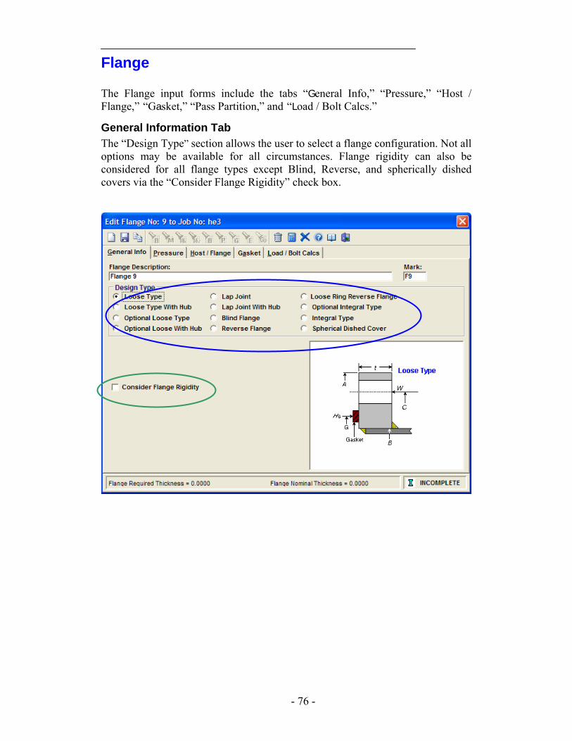
Flange The Flange input forms include the tabs “General Info,” “Pressure,” “Host / Flange,” “Gasket,” “Pass Partition,” and “Load / Bolt Calcs.”
General Information Tab The “Design Type” section allows the user to select a flange configuration. Not all options may be available for all circumstances. Flange rigidity can also be considered for all flange types except Blind, Reverse, and spherically dished covers via the “Consider Flange Rigidity” check box.
- 76 -
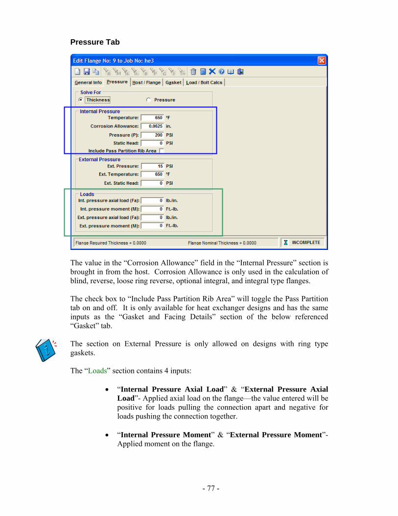
Pressure Tab
The value in the “Corrosion Allowance” field in the “Internal Pressure” section is brought in from the host. Corrosion Allowance is only used in the calculation of blind, reverse, loose ring reverse, optional integral, and integral type flanges. The check box to “Include Pass Partition Rib Area” will toggle the Pass Partition tab on and off. It is only available for heat exchanger designs and has the same inputs as the “Gasket and Facing Details” section of the below referenced “Gasket” tab. The section on External Pressure is only allowed on designs with ring type gaskets. The “Loads” section contains 4 inputs:
• “Internal Pressure Axial Load” & “External Pressure Axial Load”- Applied axial load on the flange—the value entered will be positive for loads pulling the connection apart and negative for loads pushing the connection together.
• “Internal Pressure Moment” & “External Pressure Moment”-
Applied moment on the flange.
- 77 -
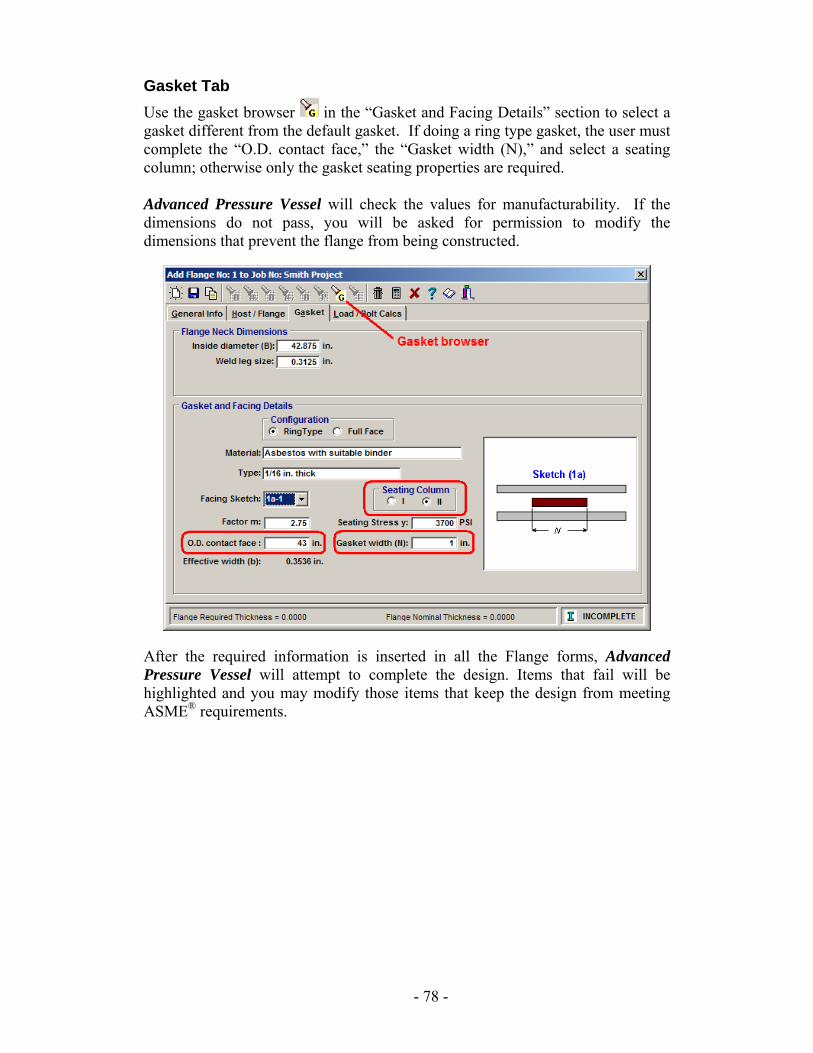
Gasket Tab Use the gasket browser in the “Gasket and Facing Details” section to select a gasket different from the default gasket. If doing a ring type gasket, the user must complete the “O.D. contact face,” the “Gasket width (N),” and select a seating column; otherwise only the gasket seating properties are required. Advanced Pressure Vessel will check the values for manufacturability. If the dimensions do not pass, you will be asked for permission to modify the dimensions that prevent the flange from being constructed.
After the required information is inserted in all the Flange forms, Advanced Pressure Vessel will attempt to complete the design. Items that fail will be highlighted and you may modify those items that keep the design from meeting ASME® requirements.
- 78 -
Analysis
7 WRC-107 General What does the WRC-107 Analysis do? – The WRC-107 Analysis calculates the combined primary membrane and local stress (primary local or secondary stress depending on many factors) at the junction of an attachment and a shell or head. When should you use it? – The method should be used for structural supports, reinforcing pad, or any shape attached to the cylinder or head that has loads applied to it. The method should also be used for nozzles that are subject to loadings in combination with or other than pressure. What are the limitations? – The analysis is based on empirical data. Certain geometries falling outside this data have no experimental basis to back them up and the result cannot be predicted with this method. Likewise, the method is not intended for the combination of external pressure and external loads on the host/attachment junction. This causes a phenomenon called inelastic instability that this method is not intended to handle.
- 79 -
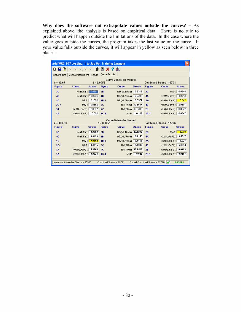
Why does the software not extrapolate values outside the curves? – As explained above, the analysis is based on empirical data. There is no rule to predict what will happen outside the limitations of the data. In the case where the value goes outside the curves, the program takes the last value on the curve. If your value falls outside the curves, it will appear in yellow as seen below in three places.
- 80 -
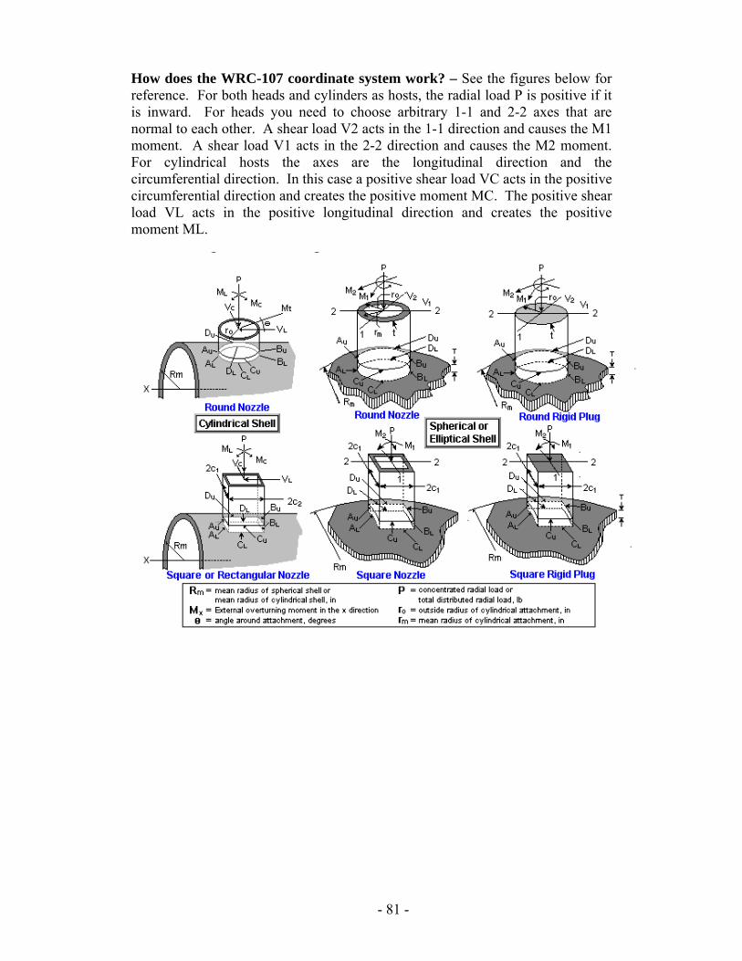
How does the WRC-107 coordinate system work? – See the figures below for reference. For both heads and cylinders as hosts, the radial load P is positive if it is inward. For heads you need to choose arbitrary 1-1 and 2-2 axes that are normal to each other. A shear load V2 acts in the 1-1 direction and causes the M1 moment. A shear load V1 acts in the 2-2 direction and causes the M2 moment. For cylindrical hosts the axes are the longitudinal direction and the circumferential direction. In this case a positive shear load VC acts in the positive circumferential direction and creates the positive moment MC. The positive shear load VL acts in the positive longitudinal direction and creates the positive moment ML.
- 81 -
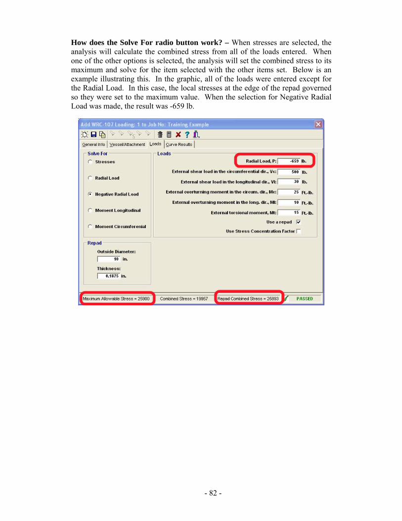
How does the Solve For radio button work? – When stresses are selected, the analysis will calculate the combined stress from all of the loads entered. When one of the other options is selected, the analysis will set the combined stress to its maximum and solve for the item selected with the other items set. Below is an example illustrating this. In the graphic, all of the loads were entered except for the Radial Load. In this case, the local stresses at the edge of the repad governed so they were set to the maximum value. When the selection for Negative Radial Load was made, the result was -659 lb.
- 82 -
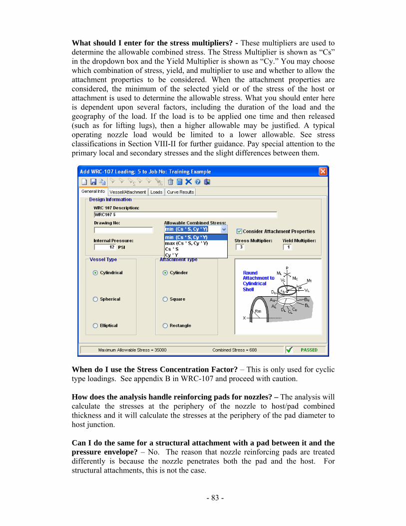
What should I enter for the stress multipliers? - These multipliers are used to determine the allowable combined stress. The Stress Multiplier is shown as “Cs” in the dropdown box and the Yield Multiplier is shown as “Cy.” You may choose which combination of stress, yield, and multiplier to use and whether to allow the attachment properties to be considered. When the attachment properties are considered, the minimum of the selected yield or of the stress of the host or attachment is used to determine the allowable stress. What you should enter here is dependent upon several factors, including the duration of the load and the geography of the load. If the load is to be applied one time and then released (such as for lifting lugs), then a higher allowable may be justified. A typical operating nozzle load would be limited to a lower allowable. See stress classifications in Section VIII-II for further guidance. Pay special attention to the primary local and secondary stresses and the slight differences between them.
When do I use the Stress Concentration Factor? – This is only used for cyclic type loadings. See appendix B in WRC-107 and proceed with caution. How does the analysis handle reinforcing pads for nozzles? – The analysis will calculate the stresses at the periphery of the nozzle to host/pad combined thickness and it will calculate the stresses at the periphery of the pad diameter to host junction. Can I do the same for a structural attachment with a pad between it and the pressure envelope? – No. The reason that nozzle reinforcing pads are treated differently is because the nozzle penetrates both the pad and the host. For structural attachments, this is not the case.
- 83 -
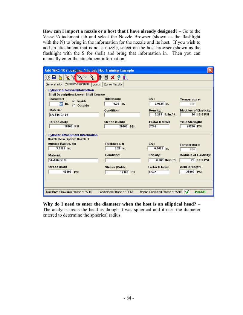
How can I import a nozzle or a host that I have already designed? – Go to the Vessel/Attachment tab and select the Nozzle Browser (shown as the flashlight with the N) to bring in the information for the nozzle and its host. If you wish to add an attachment that is not a nozzle, select on the host browser (shown as the flashlight with the S for shell) and bring that information in. Then you can manually enter the attachment information.
Why do I need to enter the diameter when the host is an elliptical head? – The analysis treats the head as though it was spherical and it uses the diameter entered to determine the spherical radius.
- 84 -
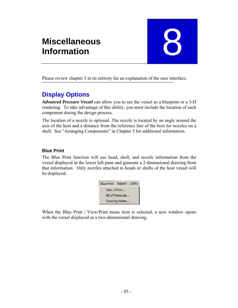
Miscellaneous Information
Please review chapter 3 in its entirety for an explanation of the user interface.
8 Display Options Advanced Pressure Vessel can allow you to see the vessel as a blueprint or a 3-D rendering. To take advantage of this ability, you must include the location of each component during the design process.
The location of a nozzle is optional. The nozzle is located by an angle around the axis of the host and a distance from the reference line of the host for nozzles on a shell. See “Arranging Components” in Chapter 5 for additional information.
Blue Print The Blue Print function will use head, shell, and nozzle information from the vessel displayed in the lower left pane and generate a 2 dimensional drawing from that information. Only nozzles attached to heads or shells of the host vessel will be displayed.
When the Blue Print | View/Print menu item is selected, a new window opens with the vessel displayed as a two-dimensional drawing.
- 85 -
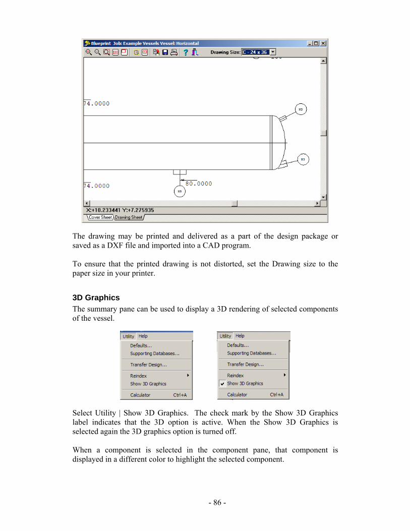
The drawing may be printed and delivered as a part of the design package or saved as a DXF file and imported into a CAD program. To ensure that the printed drawing is not distorted, set the Drawing size to the paper size in your printer.
3D Graphics The summary pane can be used to display a 3D rendering of selected components of the vessel.
Select Utility | Show 3D Graphics. The check mark by the Show 3D Graphics label indicates that the 3D option is active. When the Show 3D Graphics is selected again the 3D graphics option is turned off. When a component is selected in the component pane, that component is displayed in a different color to highlight the selected component.
- 86 -
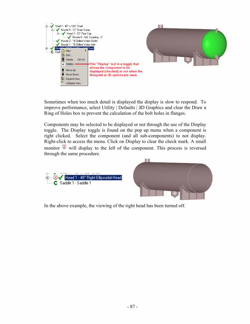
Sometimes when too much detail is displayed the display is slow to respond. To improve performance, select Utility | Defaults | 3D Graphics and clear the Draw a Ring of Holes box to prevent the calculation of the bolt holes in flanges. Components may be selected to be displayed or not through the use of the Display toggle. The Display toggle is found on the pop up menu when a component is right clicked. Select the component (and all sub-components) to not display. Right-click to access the menu. Click on Display to clear the check mark. A small monitor will display to the left of the component. This process is reversed through the same procedure.
In the above example, the viewing of the right head has been turned off.
- 87 -
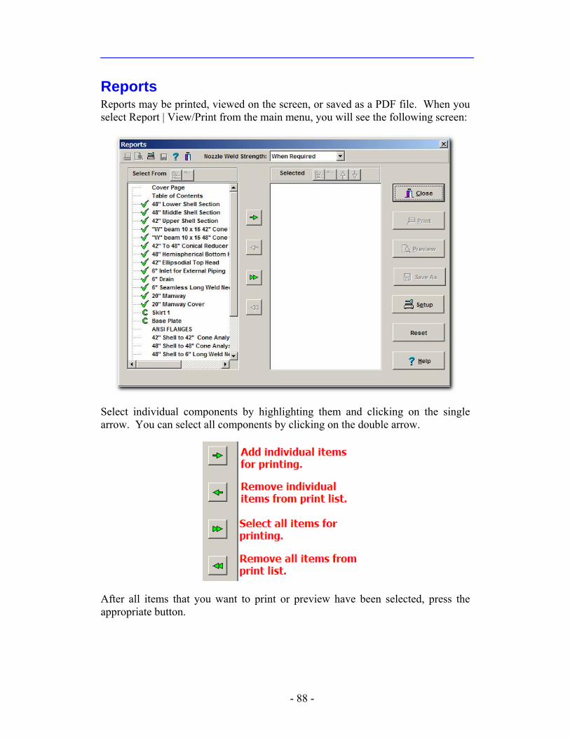
Reports Reports may be printed, viewed on the screen, or saved as a PDF file. When you select Report | View/Print from the main menu, you will see the following screen:
Select individual components by highlighting them and clicking on the single arrow. You can select all components by clicking on the double arrow.
After all items that you want to print or preview have been selected, press the appropriate button.
- 88 -
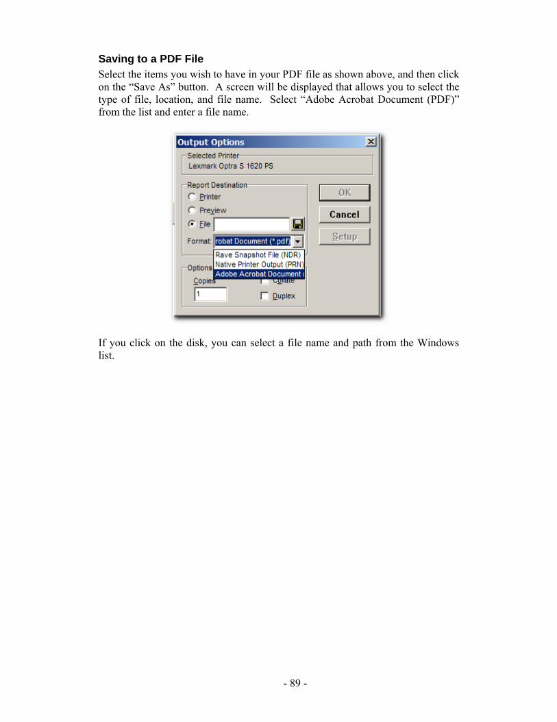
Saving to a PDF File Select the items you wish to have in your PDF file as shown above, and then click on the “Save As” button. A screen will be displayed that allows you to select the type of file, location, and file name. Select “Adobe Acrobat Document (PDF)” from the list and enter a file name.
If you click on the disk, you can select a file name and path from the Windows list.
- 89 -
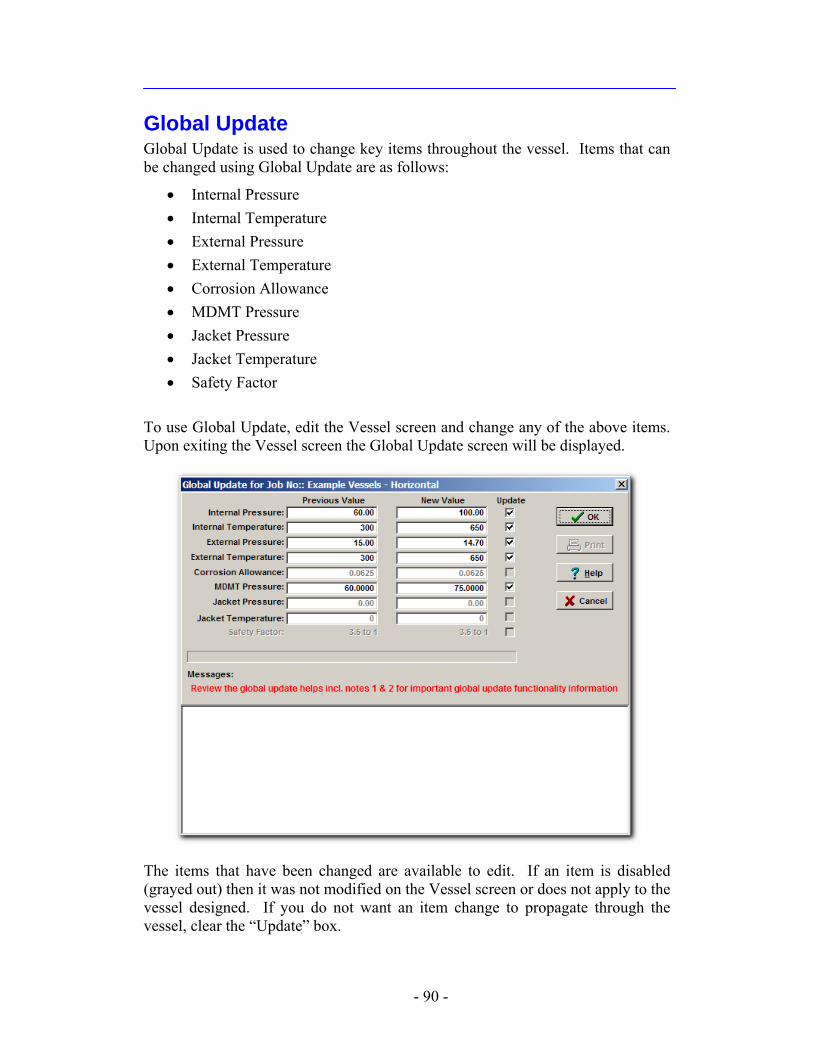
Global Update Global Update is used to change key items throughout the vessel. Items that can be changed using Global Update are as follows:
• Internal Pressure • Internal Temperature • External Pressure • External Temperature • Corrosion Allowance • MDMT Pressure • Jacket Pressure • Jacket Temperature • Safety Factor
To use Global Update, edit the Vessel screen and change any of the above items. Upon exiting the Vessel screen the Global Update screen will be displayed.
The items that have been changed are available to edit. If an item is disabled (grayed out) then it was not modified on the Vessel screen or does not apply to the vessel designed. If you do not want an item change to propagate through the vessel, clear the “Update” box.
- 90 -
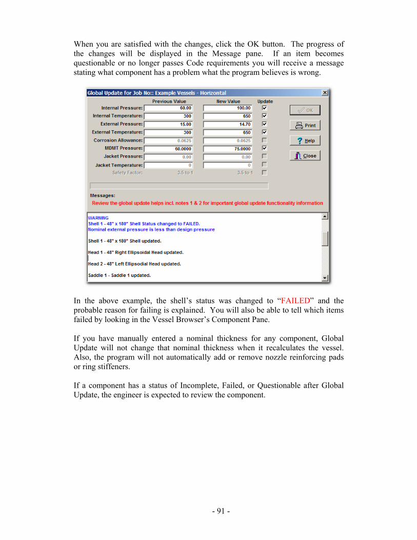
When you are satisfied with the changes, click the OK button. The progress of the changes will be displayed in the Message pane. If an item becomes questionable or no longer passes Code requirements you will receive a message stating what component has a problem what the program believes is wrong.
In the above example, the shell’s status was changed to “FAILED” and the probable reason for failing is explained. You will also be able to tell which items failed by looking in the Vessel Browser’s Component Pane. If you have manually entered a nominal thickness for any component, Global Update will not change that nominal thickness when it recalculates the vessel. Also, the program will not automatically add or remove nozzle reinforcing pads or ring stiffeners. If a component has a status of Incomplete, Failed, or Questionable after Global Update, the engineer is expected to review the component.
- 91 -
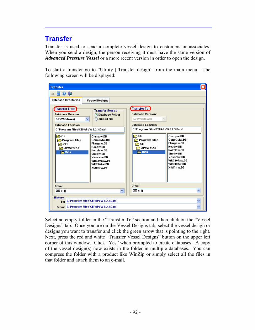
Transfer Transfer is used to send a complete vessel design to customers or associates. When you send a design, the person receiving it must have the same version of Advanced Pressure Vessel or a more recent version in order to open the design. To start a transfer go to “Utility | Transfer design” from the main menu. The following screen will be displayed:
Select an empty folder in the “Transfer To” section and then click on the “Vessel Designs” tab. Once you are on the Vessel Designs tab, select the vessel design or designs you want to transfer and click the green arrow that is pointing to the right. Next, press the red and white “Transfer Vessel Designs” button on the upper left corner of this window. Click “Yes” when prompted to create databases. A copy of the vessel design(s) now exists in the folder in multiple databases. You can compress the folder with a product like WinZip or simply select all the files in that folder and attach them to an e-mail.
- 92 -

Tip
The “To” and “From” drop-downs shown at the bottom of the snapshot store the last 10 file paths selected and can be used for quick selection.
- 93 -
Seismic Inputs ASCE 7-98 1. Determine the short period spectral response acceleration, , from Figures
9.4.1.1(a) – (j).SS
i 2. Determine the 1 second spectral response acceleration, , from Figures
9.4.1.1(a) – (j).1S
ii 3. Determine the Occupancy Category per Table 1-1 and then the Seismic Use
Group per Paragraph 9.1.3.iii 4. Determine the Site Class per Paragraph 9.4.1.2 and Table 9.4.1.2.iv 5. Determine the Response Modification Factor from Table 9.14.2.1.v
IBC 2000 1. Determine the short period spectral response acceleration, , from Figures
1615(1) – (10).SS
vi 2. Determine the 1 second spectral response acceleration, , from Figures
1615(1) – (10).1S
vii 3. Determine the Occupancy Category per Table 1604.5 and then the Seismic
Use Group per Paragraph 1616.2.viii 4. Determine the Site Class per 1615.1.1.ix 5. Determine the Response Modification Factor from Table 1622.2.5(1).x
ASCE 7-02 and IBC 2003 1. Determine the short period spectral response acceleration, , from ASCE 7-
02 Figures 9.4.1.1(a) – (j) for both ASCE 7-02 and IBC 2003.SS
xi 2. Determine the 1 second spectral response acceleration, , from ASCE 7-02
Figures 9.4.1.1(a) – (j) for both ASCE 7-02 and IBC 2003.1S
xii 3. Determine the Occupancy Category per ASCE 7-02 Table 1-1xiii and then the
Seismic Use Group per ASCE 7-02 Table 9.14.5.1.2 for both ASCE 7-02 and IBC 2003.xiv
4. Determine the Site Class per ASCE 7-02 9.4.1.2 for both ASCE 7-02 and IBC 2003.xv
5. Determine the Response Modification Factor from ASCE 7-02 Table 9.14.5.1.1for both ASCE 7-02 and IBC 2003.xvi
ASCE 7-05 and IBC 2006 1. Determine the short period spectral response acceleration, , from Figures
22-1 through 22-14 for ASCE 7-05 and Figures 1613.5(1) through 1613.5(14) for IBC 2006.
SS
xvii
- 94 -
2. Determine the 1 second spectral response acceleration, , from Figures 22-1 through 22-14 for ASCE 7-05 and Figures 1613.5(1) through 1613.5(14) for IBC 2006.
1S
xviii 3. Determine the long period transition period, , from ASCE 7-05 Figures 22-
15 through 22-20 for both ASCE 7-05 and IBC 2006.LT
xix 4. Determine the Occupancy Category per Table 1-1 for ASCE 7-05 and Table
1604.5 for IBC 2006.xx 5. Determine the Site Class per Section 11.4.2 and chapter 20 for ASCE 7-05
and Sections 1613.5.2 and 1613.5.5 for IBC 2006xxi. 6. Determine the Response Modification Factor from ASCE 7-05 Table 15.4-2
for both ASCE 7-05 and IBC 2006.xxii i ASCE 7-98, Par. 9.4.1.1, pg. 98. ii Ibid. iii ASCE 7-98, Par. 9.1.3, pg. 98. iv ASCE 7-98, Par. 9.4.1.2, pg. 98; ASCE 7-98, Table 9.4.1.2, pg. 118. v ASCE 7-98, Table 9.14.2.1, pgs 177 and 178. vi IBC 2000, Par. 1615.1, pg. 331. vii Ibid. viii IBC 2000, Par. 1616.2, pg. 354. ix IBC 2000, Par. 1615.1.1, pg. 350. x IBC 2000, Par. 1622.2.5 Step 1, pg. 387. xi ASCE 7-02, 9.4.1.2.4, pg. 129. xii Ibid. xiii ASCE 7-02, Table 1-1, pg. 4. xiv ASCE 7-02, Table 9.14.5.1.2, pg. 192. xv ASCE 7-02, Par. 9.4.1.2, pg. 107. xvi ASCE 7-02, Par. 9.14.5.1 Step 1, pg. 188. xvii ASCE 7-05, 11.4.1, pg. 115; IBC 2006, 1613.5.1, pg. 303. xviii Ibid. xix ASCE 7-05, 11.4.5, pg. 116. xx ASCE 7-05, Table 1-1, pg. 3; IBC 2006, Table 1604.5, pg. 281. xxi ASCE 7-05, 11.4.2, pg. 115 ; IBC 2006, 1613.5.2, pg. 303. xxii ASCE 7-05, 15.4.1 Step (1)(b), pg. 162.
- 95 -
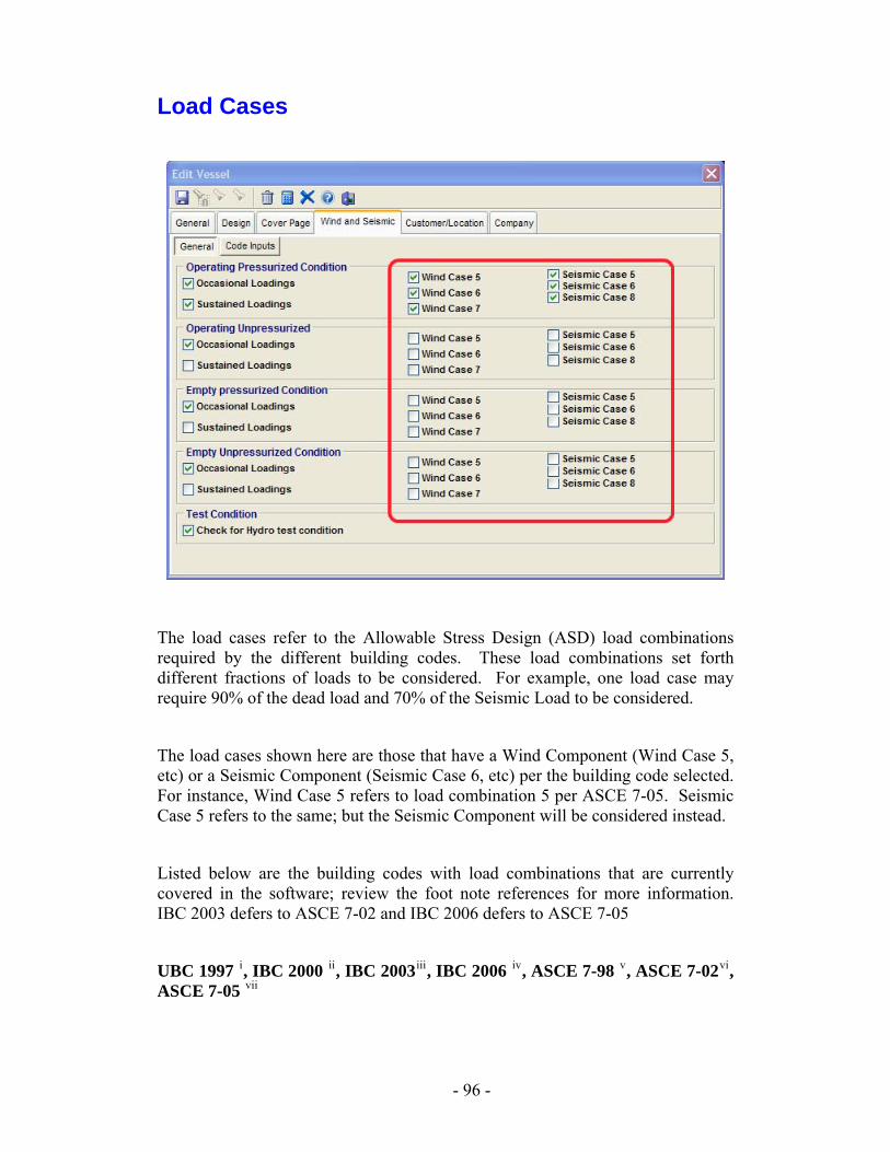
Load Cases
The load cases refer to the Allowable Stress Design (ASD) load combinations required by the different building codes. These load combinations set forth different fractions of loads to be considered. For example, one load case may require 90% of the dead load and 70% of the Seismic Load to be considered.
The load cases shown here are those that have a Wind Component (Wind Case 5, etc) or a Seismic Component (Seismic Case 6, etc) per the building code selected. For instance, Wind Case 5 refers to load combination 5 per ASCE 7-05. Seismic Case 5 refers to the same; but the Seismic Component will be considered instead.
Listed below are the building codes with load combinations that are currently covered in the software; review the foot note references for more information. IBC 2003 defers to ASCE 7-02 and IBC 2006 defers to ASCE 7-05
UBC 1997 i, IBC 2000 ii, IBC 2003iii, IBC 2006 iv, ASCE 7-98 v, ASCE 7-02vi, ASCE 7-05 vii
- 96 -
i UBC 1997, Par 1630.1, pg. 2-13; UBC 1997, Par. 1612.3.1, pg. 2-4 ii IBC 2000, Par. 1617.1.1, pgs 357 and 358; IBC 2000, Par. 1605.3.1, pg. 298 iii ASCE 7-02, Par. 2.4.1, pg. 6; ASCE 7-02, Table 9.5.2.5.1, pg. 140; ASCE 7-02, Par. 9.5.3, pg. 145 iv ASCE 7-05, Par. 2.4.1, pg. 5; ASCE 7-05, Par. 11.7, pgs 116 - 117 v ASCE 7-98, Par. 9.5.2.7, pgs 134 and 135; ASCE 7-98, Par. 2.4.1, pg. 5 vi ASCE 7-02, Par. 2.4.1, pg. 6; ASCE 7-02, Table 9.5.2.5.1, pg. 140; ASCE 7-02, Par. 9.5.3, pg. 145 vii ASCE 7-05, Par. 2.4.1, pg. 5; ASCE 7-05, Par. 11.7, pgs 116 - 117
- 97 -

- 98 -
Add-in Modules
There are four add-in modules available for Advanced Pressure Vessel. By offering add-in modules, Computer Engineering allows the user to choose only those features needed. The ability to choose modules saves unnecessary cost. All modules have the ability to perform wind and seismic analysis. Wind analysis and seismic shear calculations can be performed in accordance with ASCE/ANSI, or the International Building Code (IBC).
9
Heat Exchanger Module The Heat Exchanger module for Advanced Pressure Vessel allows you to create heat exchanger components per ASME Section VIII Division I. This includes Tubesheets per Part UHX, Expansion Joints per Appendices 5 and 26, and Tube-to-Tubesheet Welds per Part UW-20 and Appendix A. The types of heat exchangers within the scope of the ASME® Boiler and Pressure Vessel Code, and therefore allowed in Advanced Pressure Vessel, are exclusively shell and tube type heat exchangers. Though it may be possible to have more than two compartments, the components designed will be either Tube-Side or Shell-Side and they break down as follows:
• Tube-Side components: Tubes, Channel Shells, Channel Heads, and Channel Conical Reducers.
• Shell-Side Components: Shells, Heads, Cones, Thick Walled Expansion Joints, and Thin Walled Expansion Joints.
Tubesheets are not included in either list because they are a common component and will need values from both the shell side and the tube side. Subcomponents, such as nozzles and flanges, will be either Shell-Side or Tube-Side depending on their host. Tube-Side components will default to the Tube Temperature, Tube Pressure, Tube Specific Gravity, and Tube-Side Radiography from the General tab and Design Info tab on the Add/Edit Vessel Screens. Likewise, Shell-Side components will default to the Shell Temperature, Shell Pressure, Specific Gravity, and Radiography from the same locations.
- 99 -
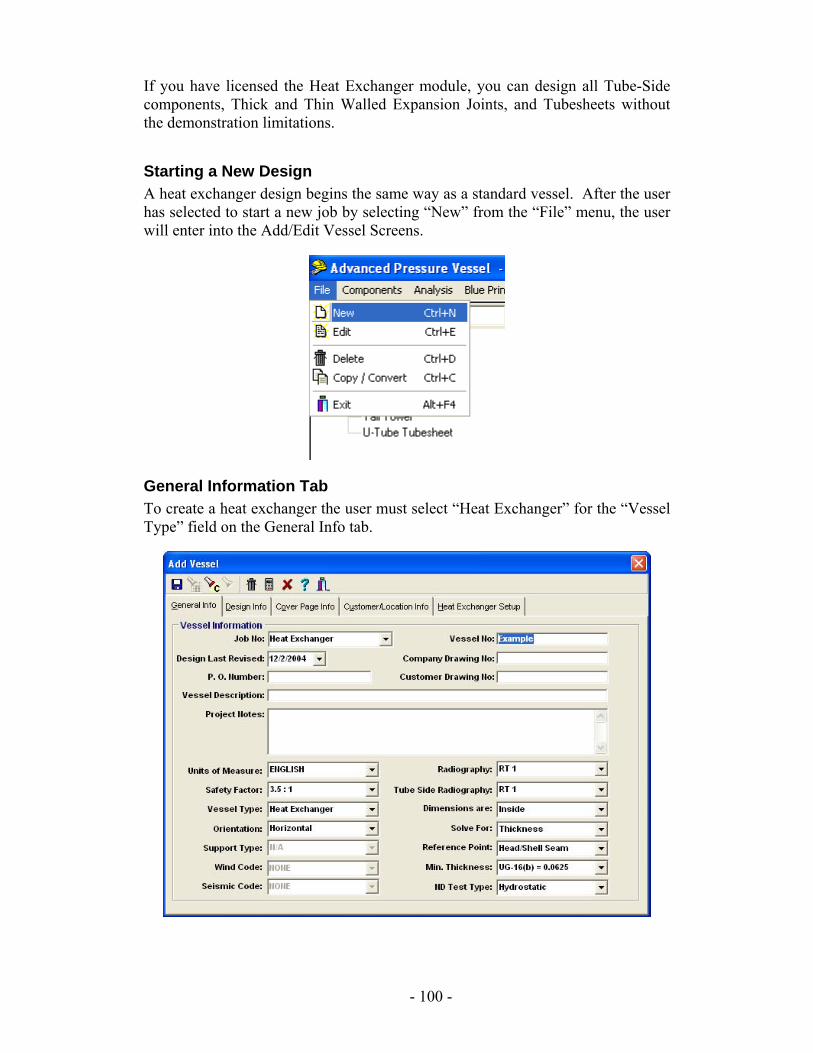
If you have licensed the Heat Exchanger module, you can design all Tube-Side components, Thick and Thin Walled Expansion Joints, and Tubesheets without the demonstration limitations.
Starting a New Design A heat exchanger design begins the same way as a standard vessel. After the user has selected to start a new job by selecting “New” from the “File” menu, the user will enter into the Add/Edit Vessel Screens.
General Information Tab To create a heat exchanger the user must select “Heat Exchanger” for the “Vessel Type” field on the General Info tab.
- 100 -
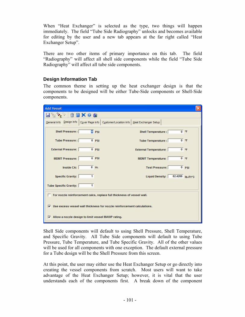
When “Heat Exchanger” is selected as the type, two things will happen immediately. The field “Tube Side Radiography” unlocks and becomes available for editing by the user and a new tab appears at the far right called “Heat Exchanger Setup”. There are two other items of primary importance on this tab. The field “Radiography” will affect all shell side components while the field “Tube Side Radiography” will affect all tube side components.
Design Information Tab The common theme in setting up the heat exchanger design is that the components to be designed will be either Tube-Side components or Shell-Side components.
Shell Side components will default to using Shell Pressure, Shell Temperature, and Specific Gravity. All Tube Side components will default to using Tube Pressure, Tube Temperature, and Tube Specific Gravity. All of the other values will be used for all components with one exception. The default external pressure for a Tube design will be the Shell Pressure from this screen. At this point, the user may either use the Heat Exchanger Setup or go directly into creating the vessel components from scratch. Most users will want to take advantage of the Heat Exchanger Setup; however, it is vital that the user understands each of the components first. A break down of the component
- 101 -
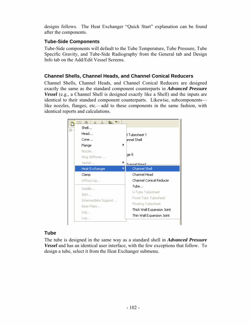
designs follows. The Heat Exchanger “Quick Start” explanation can be found after the components.
Tube-Side Components Tube-Side components will default to the Tube Temperature, Tube Pressure, Tube Specific Gravity, and Tube-Side Radiography from the General tab and Design Info tab on the Add/Edit Vessel Screens.
Channel Shells, Channel Heads, and Channel Conical Reducers Channel Shells, Channel Heads, and Channel Conical Reducers are designed exactly the same as the standard component counterparts in Advanced Pressure Vessel (e.g., a Channel Shell is designed exactly like a Shell) and the inputs are identical to their standard component counterparts. Likewise, subcomponents—like nozzles, flanges, etc.—add to these components in the same fashion, with identical reports and calculations.
Tube The tube is designed in the same way as a standard shell in Advanced Pressure Vessel and has an identical user interface, with the few exceptions that follow. To design a tube, select it from the Heat Exchanger submenu.
- 102 -
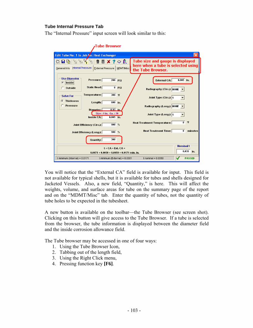
Tube Internal Pressure Tab The “Internal Pressure” input screen will look similar to this:
You will notice that the “External CA” field is available for input. This field is not available for typical shells, but it is available for tubes and shells designed for Jacketed Vessels. Also, a new field, “Quantity,” is here. This will affect the weights, volume, and surface areas for tube on the summary page of the report and on the “MDMT/Misc” tab. Enter the quantity of tubes, not the quantity of tube holes to be expected in the tubesheet. A new button is available on the toolbar—the Tube Browser (see screen shot). Clicking on this button will give access to the Tube Browser. If a tube is selected from the browser, the tube information is displayed between the diameter field and the inside corrosion allowance field. The Tube browser may be accessed in one of four ways:
1. Using the Tube Browser Icon, 2. Tabbing out of the length field, 3. Using the Right Click menu, 4. Pressing function key [F6].
- 103 -
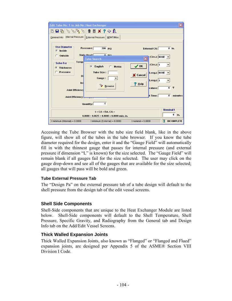
Accessing the Tube Browser with the tube size field blank, like in the above figure, will show all of the tubes in the tube browser. If you know the tube diameter required for the design, enter it and the “Gauge Field” will automatically fill in with the thinnest gauge that passes for internal pressure (and external pressure if dimension “L” is known) for the size selected. The “Gauge Field” will remain blank if all gauges fail for the size selected. The user may click on the gauge drop-down and see all of the gauges that are available for the size selected; all gauges that will pass will be bold and green.
Tube External Pressure Tab The “Design Pa” on the external pressure tab of a tube design will default to the shell pressure from the design tab of the edit vessel screens.
Shell Side Components Shell-Side components that are unique to the Heat Exchanger Module are listed below. Shell-Side components will default to the Shell Temperature, Shell Pressure, Specific Gravity, and Radiography from the General tab and Design Info tab on the Add/Edit Vessel Screens.
Thick Walled Expansion Joints Thick Walled Expansion Joints, also known as “Flanged” or “Flanged and Flued” expansion joints, are designed per Appendix 5 of the ASME® Section VIII Division I Code.
- 104 -
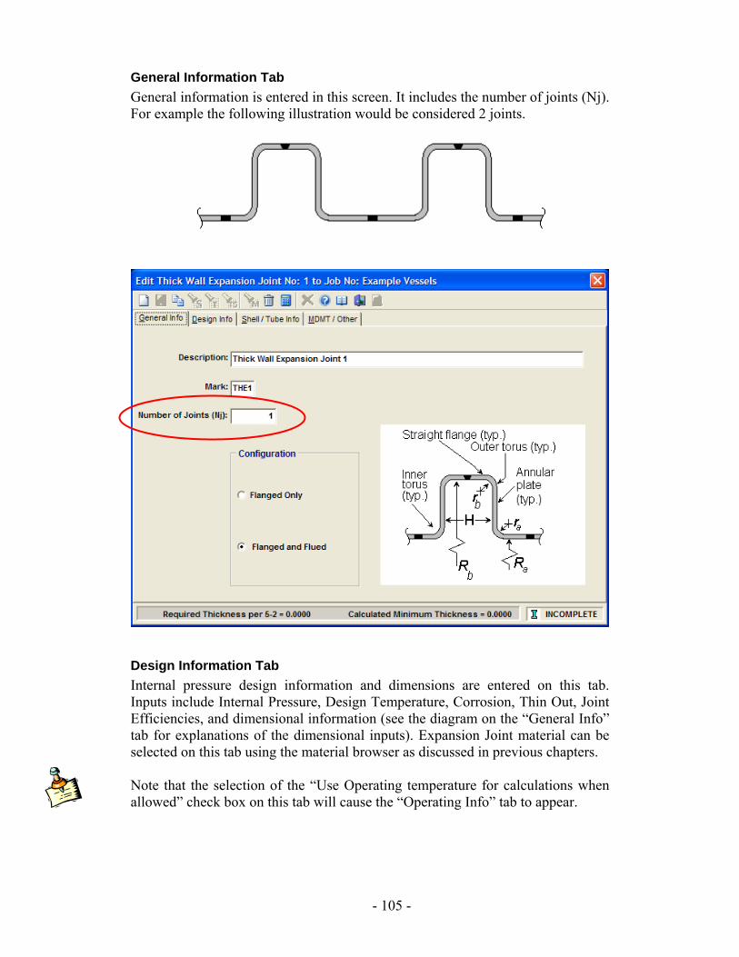
General Information Tab General information is entered in this screen. It includes the number of joints (Nj). For example the following illustration would be considered 2 joints.
Design Information Tab Internal pressure design information and dimensions are entered on this tab. Inputs include Internal Pressure, Design Temperature, Corrosion, Thin Out, Joint Efficiencies, and dimensional information (see the diagram on the “General Info” tab for explanations of the dimensional inputs). Expansion Joint material can be selected on this tab using the material browser as discussed in previous chapters. Note that the selection of the “Use Operating temperature for calculations when allowed” check box on this tab will cause the “Operating Info” tab to appear.
- 105 -
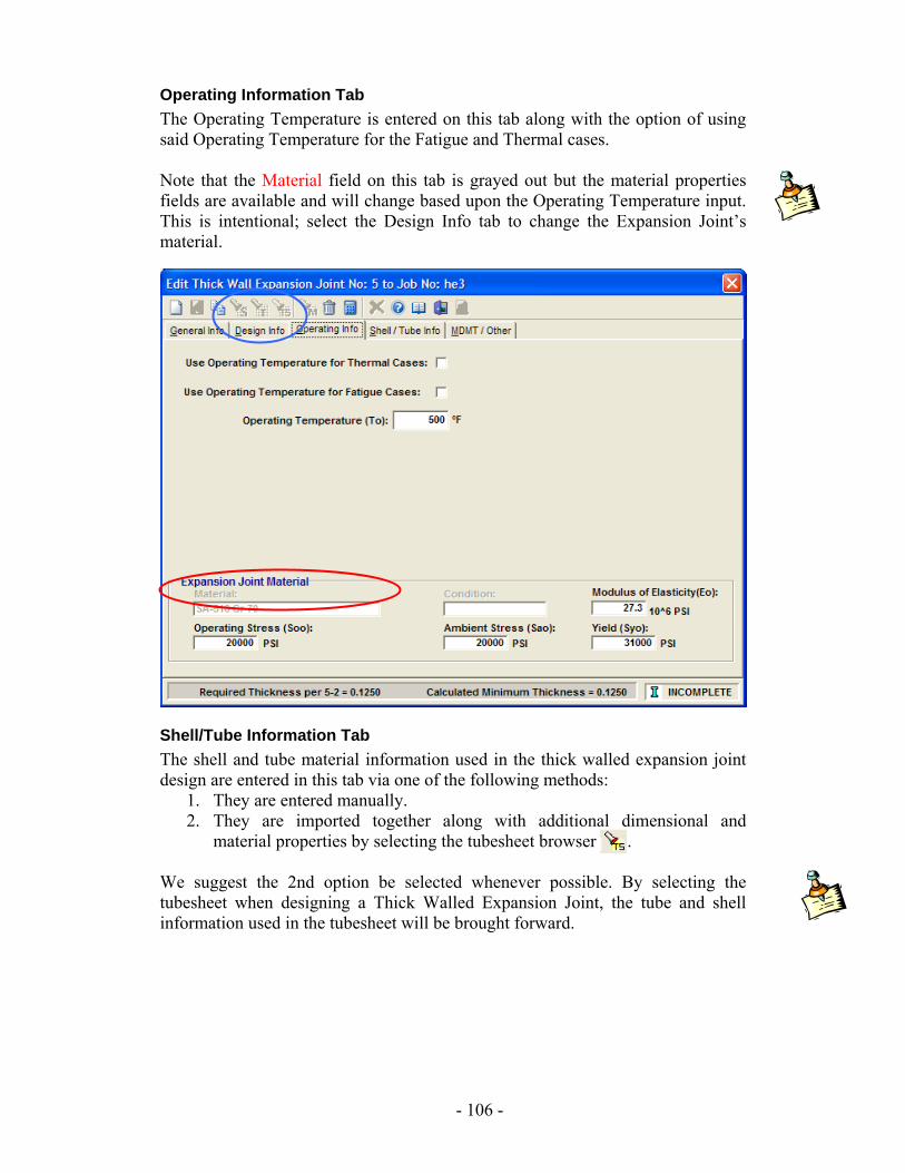
Operating Information Tab The Operating Temperature is entered on this tab along with the option of using said Operating Temperature for the Fatigue and Thermal cases. Note that the Material field on this tab is grayed out but the material properties fields are available and will change based upon the Operating Temperature input. This is intentional; select the Design Info tab to change the Expansion Joint’s material.
Shell/Tube Information Tab The shell and tube material information used in the thick walled expansion joint design are entered in this tab via one of the following methods:
1. They are entered manually. 2. They are imported together along with additional dimensional and
material properties by selecting the tubesheet browser . We suggest the 2nd option be selected whenever possible. By selecting the tubesheet when designing a Thick Walled Expansion Joint, the tube and shell information used in the tubesheet will be brought forward.
- 106 -
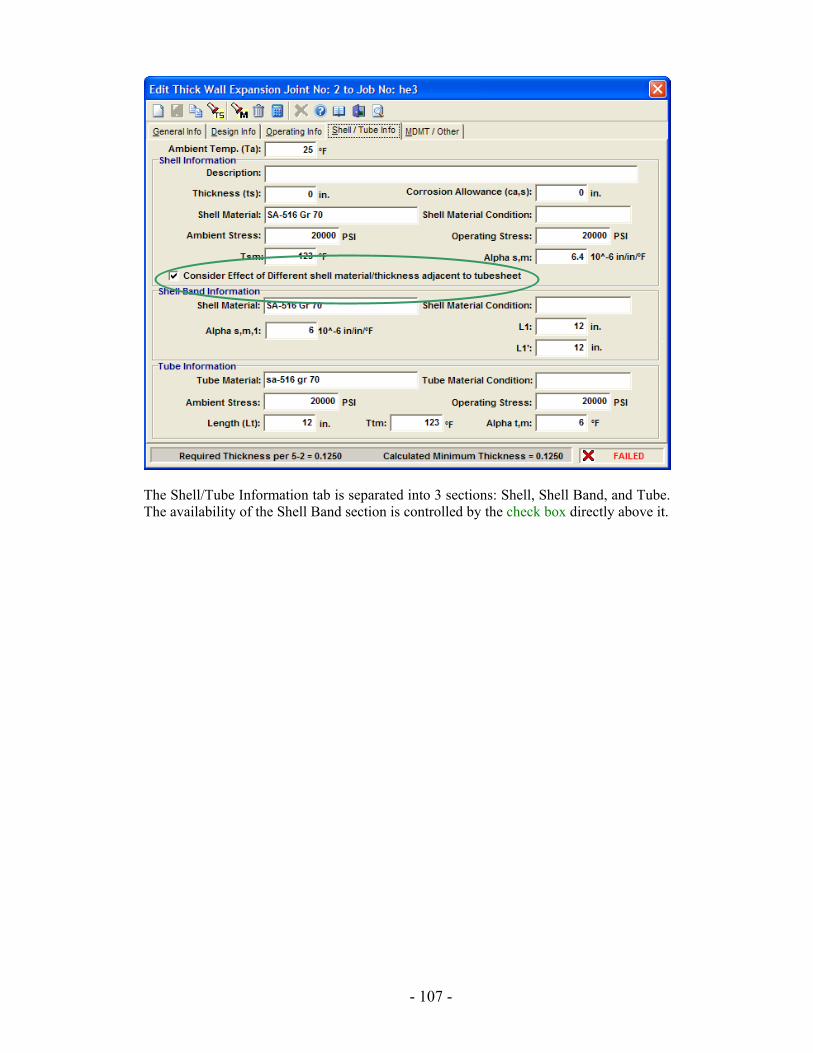
The Shell/Tube Information tab is separated into 3 sections: Shell, Shell Band, and Tube. The availability of the Shell Band section is controlled by the check box directly above it.
- 107 -
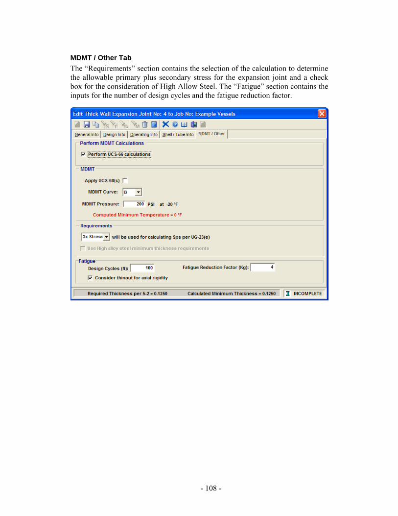
MDMT / Other Tab The “Requirements” section contains the selection of the calculation to determine the allowable primary plus secondary stress for the expansion joint and a check box for the consideration of High Allow Steel. The “Fatigue” section contains the inputs for the number of design cycles and the fatigue reduction factor.
- 108 -
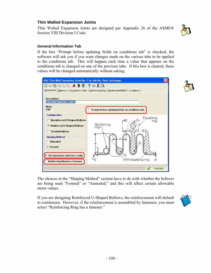
Thin Walled Expansion Joints Thin Walled Expansion Joints are designed per Appendix 26 of the ASME® Section VIII Division I Code.
General Information Tab If the box “Prompt before updating fields on conditions tab” is checked, the software will ask you if you want changes made on the various tabs to be applied to the conditions tab. This will happen each time a value that appears on the conditions tab is changed on one of the previous tabs. If this box is cleared, these values will be changed automatically without asking.
The choices in the “Shaping Method” section have to do with whether the bellows are being used “Formed” or “Annealed,” and this will affect certain allowable stress values. If you are designing Reinforced U-Shaped Bellows, the reinforcement will default to continuous. However, if the reinforcement is assembled by fasteners, you must select “Reinforcing Ring has a fastener.”
- 109 -
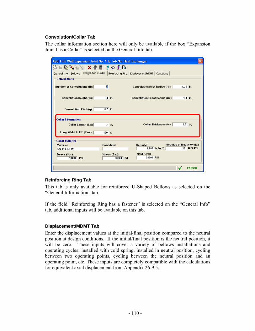
Convolution/Collar Tab The collar information section here will only be available if the box “Expansion Joint has a Collar” is selected on the General Info tab.
Reinforcing Ring Tab This tab is only available for reinforced U-Shaped Bellows as selected on the “General Information” tab. If the field “Reinforcing Ring has a fastener” is selected on the “General Info” tab, additional inputs will be available on this tab.
Displacement/MDMT Tab Enter the displacement values at the initial/final position compared to the neutral position at design conditions. If the initial/final position is the neutral position, it will be zero. These inputs will cover a variety of bellows installations and operating cycles: installed with cold spring, installed in neutral position, cycling between two operating points, cycling between the neutral position and an operating point, etc. These inputs are completely compatible with the calculations for equivalent axial displacement from Appendix 26-9.5.
- 110 -
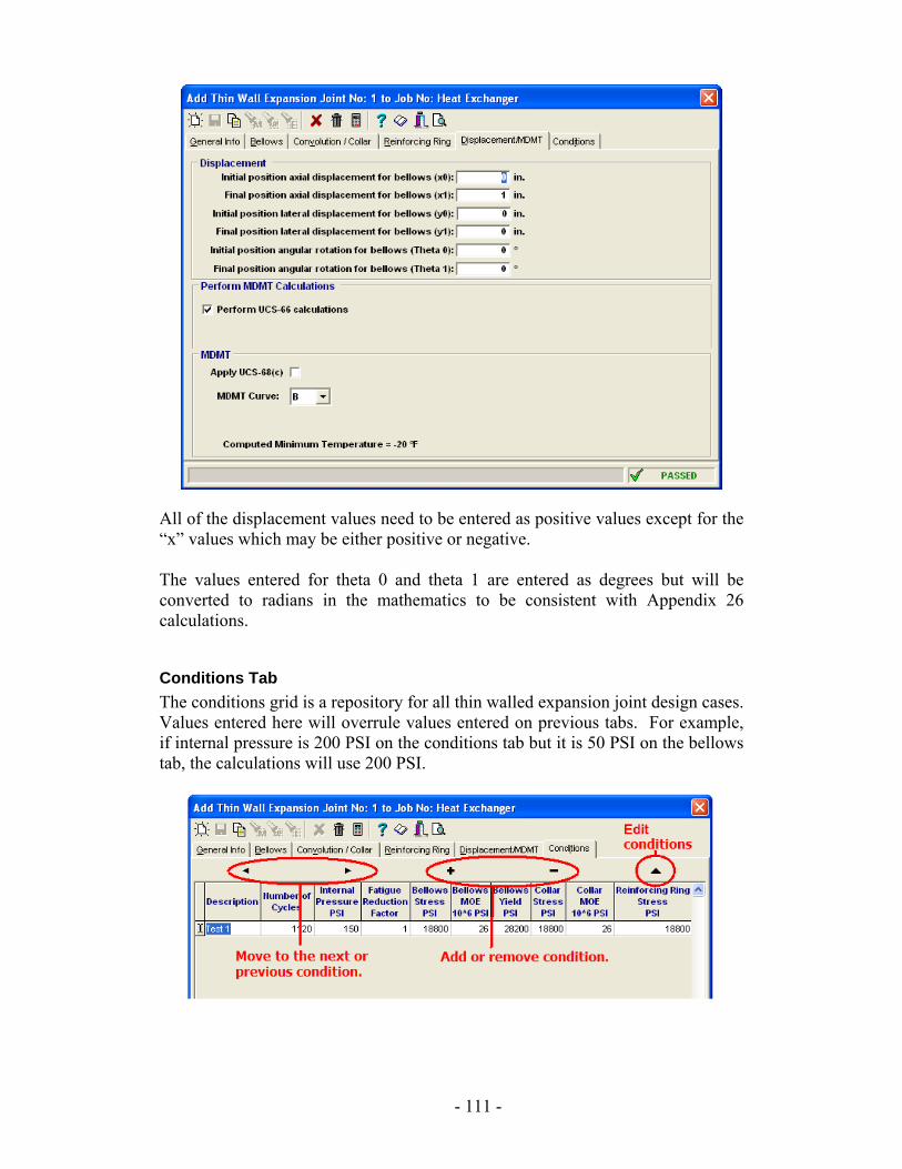
All of the displacement values need to be entered as positive values except for the “x” values which may be either positive or negative. The values entered for theta 0 and theta 1 are entered as degrees but will be converted to radians in the mathematics to be consistent with Appendix 26 calculations.
Conditions Tab The conditions grid is a repository for all thin walled expansion joint design cases. Values entered here will overrule values entered on previous tabs. For example, if internal pressure is 200 PSI on the conditions tab but it is 50 PSI on the bellows tab, the calculations will use 200 PSI.
- 111 -
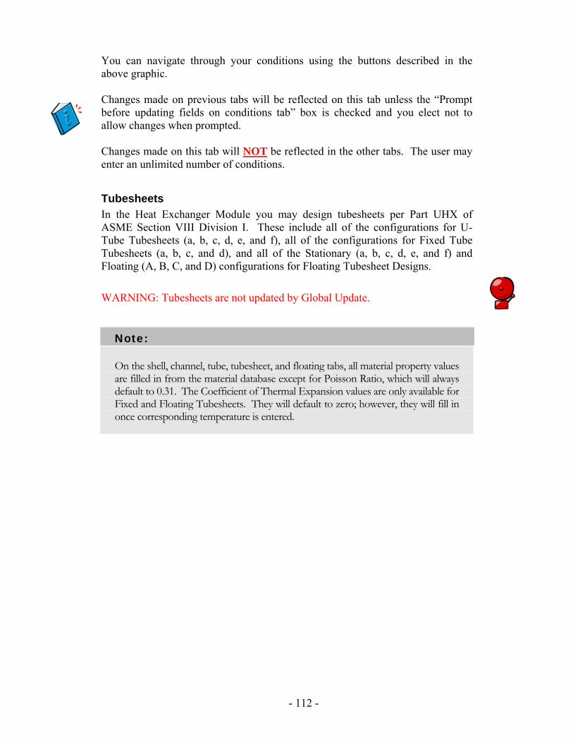
You can navigate through your conditions using the buttons described in the above graphic. Changes made on previous tabs will be reflected on this tab unless the “Prompt before updating fields on conditions tab” box is checked and you elect not to allow changes when prompted. Changes made on this tab will NOT be reflected in the other tabs. The user may enter an unlimited number of conditions.
Tubesheets In the Heat Exchanger Module you may design tubesheets per Part UHX of ASME Section VIII Division I. These include all of the configurations for U-Tube Tubesheets (a, b, c, d, e, and f), all of the configurations for Fixed Tube Tubesheets (a, b, c, and d), and all of the Stationary (a, b, c, d, e, and f) and Floating (A, B, C, and D) configurations for Floating Tubesheet Designs.
WARNING: Tubesheets are not updated by Global Update.
Note:
On the shell, channel, tube, tubesheet, and floating tabs, all material property values are filled in from the material database except for Poisson Ratio, which will always default to 0.31. The Coefficient of Thermal Expansion values are only available for Fixed and Floating Tubesheets. They will default to zero; however, they will fill in once corresponding temperature is entered.
- 112 -
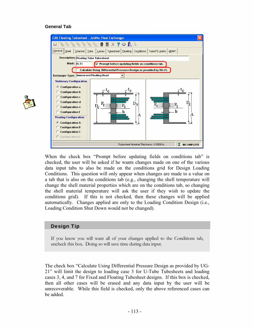
General Tab
When the check box “Prompt before updating fields on conditions tab” is checked, the user will be asked if he wants changes made on one of the various data input tabs to also be made on the conditions grid for Design Loading Conditions. This question will only appear when changes are made to a value on a tab that is also on the conditions tab (e.g., changing the shell temperature will change the shell material properties which are on the conditions tab, so changing the shell material temperature will ask the user if they wish to update the conditions grid). If this is not checked, then these changes will be applied automatically. Changes applied are only to the Loading Condition Design (i.e., Loading Condition Shut Down would not be changed).
Design Tip
If you know you will want all of your changes applied to the Conditions tab, uncheck this box. Doing so will save time during data input.
The check box “Calculate Using Differential Pressure Design as provided by UG-21” will limit the design to loading case 3 for U-Tube Tubesheets and loading cases 3, 4, and 7 for Fixed and Floating Tubesheet designs. If this box is checked, then all other cases will be erased and any data input by the user will be unrecoverable. While this field is checked, only the above referenced cases can be added.
- 113 -
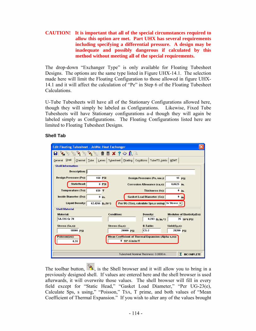
CAUTION! It is important that all of the special circumstances required to
allow this option are met. Part UHX has several requirements including specifying a differential pressure. A design may be inadequate and possibly dangerous if calculated by this method without meeting all of the special requirements.
The drop-down “Exchanger Type” is only available for Floating Tubesheet Designs. The options are the same type listed in Figure UHX-14.1. The selection made here will limit the Floating Configuration to those allowed in figure UHX-14.1 and it will affect the calculation of “Pe” in Step 6 of the Floating Tubesheet Calculations. U-Tube Tubesheets will have all of the Stationary Configurations allowed here, though they will simply be labeled as Configurations. Likewise, Fixed Tube Tubesheets will have Stationary configurations a-d though they will again be labeled simply as Configurations. The Floating Configurations listed here are limited to Floating Tubesheet Designs.
Shell Tab
The toolbar button, , is the Shell browser and it will allow you to bring in a previously designed shell. If values are entered here and the shell browser is used afterwards, it will overwrite those values. The shell browser will fill in every field except for “Static Head,” “Gasket Load Diameter,” “Per UG-23(e), Calculate Sps, s using,” “Poisson,” TSA, T prime, and both values of “Mean Coefficient of Thermal Expansion.” If you wish to alter any of the values brought
- 114 -
in by the browser, you may right click and choose “Deselect shell” from the menu. This will leave the values as brought in by the browser but will allow you to alter them. If a shell is “deselected,” any changes made in the shell design screen will no longer update the tubesheet.
Design Tip
Using the Shell Browser will save considerable time in repetitive data entry and is a way to make sure that you are designing your tubesheet with a shell that meets Code requirements.
The field Gs will be available only on Configurations d, e and f. This field will be populated by the flange browser if that is used on the tubesheet tab.
Channel Tab
The toolbar button, , is the Channel Shell browser and it will allow you to bring in a previously designed Channel Shell. Certain tubesheet configurations include an integral channel; in these cases, an integral Channel Head or an integral Channel Shell may be used. The Channel Head browser will be available for these instances. All other information on the Channel tab is very similar to the shell tab. At this time, only Hemispherical Channel Heads are available for use in tubesheets per ASME® Section 8, Div 1, Part UHX Code.
Tube Tab
The toolbar button, , is the Tube browser and it will allow you to bring in a previously designed tube.
- 115 -
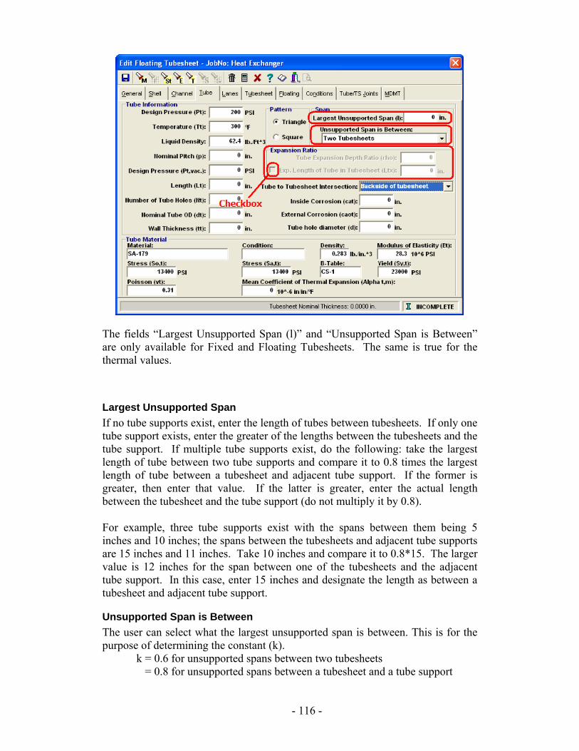
The fields “Largest Unsupported Span (l)” and “Unsupported Span is Between” are only available for Fixed and Floating Tubesheets. The same is true for the thermal values.
Largest Unsupported Span If no tube supports exist, enter the length of tubes between tubesheets. If only one tube support exists, enter the greater of the lengths between the tubesheets and the tube support. If multiple tube supports exist, do the following: take the largest length of tube between two tube supports and compare it to 0.8 times the largest length of tube between a tubesheet and adjacent tube support. If the former is greater, then enter that value. If the latter is greater, enter the actual length between the tubesheet and the tube support (do not multiply it by 0.8). For example, three tube supports exist with the spans between them being 5 inches and 10 inches; the spans between the tubesheets and adjacent tube supports are 15 inches and 11 inches. Take 10 inches and compare it to 0.8*15. The larger value is 12 inches for the span between one of the tubesheets and the adjacent tube support. In this case, enter 15 inches and designate the length as between a tubesheet and adjacent tube support.
Unsupported Span is Between The user can select what the largest unsupported span is between. This is for the purpose of determining the constant (k).
k = 0.6 for unsupported spans between two tubesheets = 0.8 for unsupported spans between a tubesheet and a tube support
- 116 -
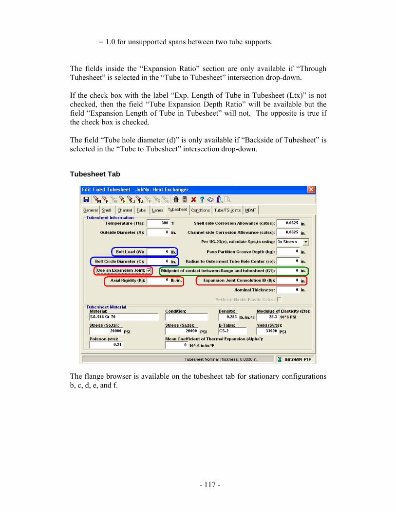
= 1.0 for unsupported spans between two tube supports. The fields inside the “Expansion Ratio” section are only available if “Through Tubesheet” is selected in the “Tube to Tubesheet” intersection drop-down. If the check box with the label “Exp. Length of Tube in Tubesheet (Ltx)” is not checked, then the field “Tube Expansion Depth Ratio” will be available but the field “Expansion Length of Tube in Tubesheet” will not. The opposite is true if the check box is checked. The field “Tube hole diameter (d)” is only available if “Backside of Tubesheet” is selected in the “Tube to Tubesheet” intersection drop-down.
Tubesheet Tab
The flange browser is available on the tubesheet tab for stationary configurations b, c, d, e, and f.
- 117 -
WARNING: Flanges must be designed as flange pairs per Section VIII, Division 1 of the Code. To do this in the software, design each flange and record the values of Wm1 and Wm2 used for each. Then, verify that both of the flanges are using the higher Wm1 and Wm2 values. If they are not, modify them such that each flange of the mating pair has the same Wm1 and the same Wm2 values. The Wm1 and Wm2 values do not need to match each other. This may still not be an exhaustive examination and further consideration may be necessary for items such as temperature, pressure, and loadings.
The thin walled expansion joint and thick walled expansion joint browsers and the check box for “Use an Expansion Joint” are only available for Fixed Tubesheets. If the check box is marked, then the fields “Axial Rigidity” and “Expansion Joint Convolution ID” will become active. The fields “Bolt Load” and “Bolt Circle Diameter” are only available for configurations b, c, d, e, and f. Instead of “Bolt Load W,” U-Tube Tubesheets will have “Bolt Load Wc” for configuration b and c, “Bolt Load Ws” for configurations e and f, and both “Bolt Load Wc” and “Bolt Load Ws” for configuration d. The field “Midpoint of contact between Flange and tube sheet G1” is only available for configurations c and f. The fields “Wm1” and “hG” are only available for configurations b, e, and B.
- 118 -
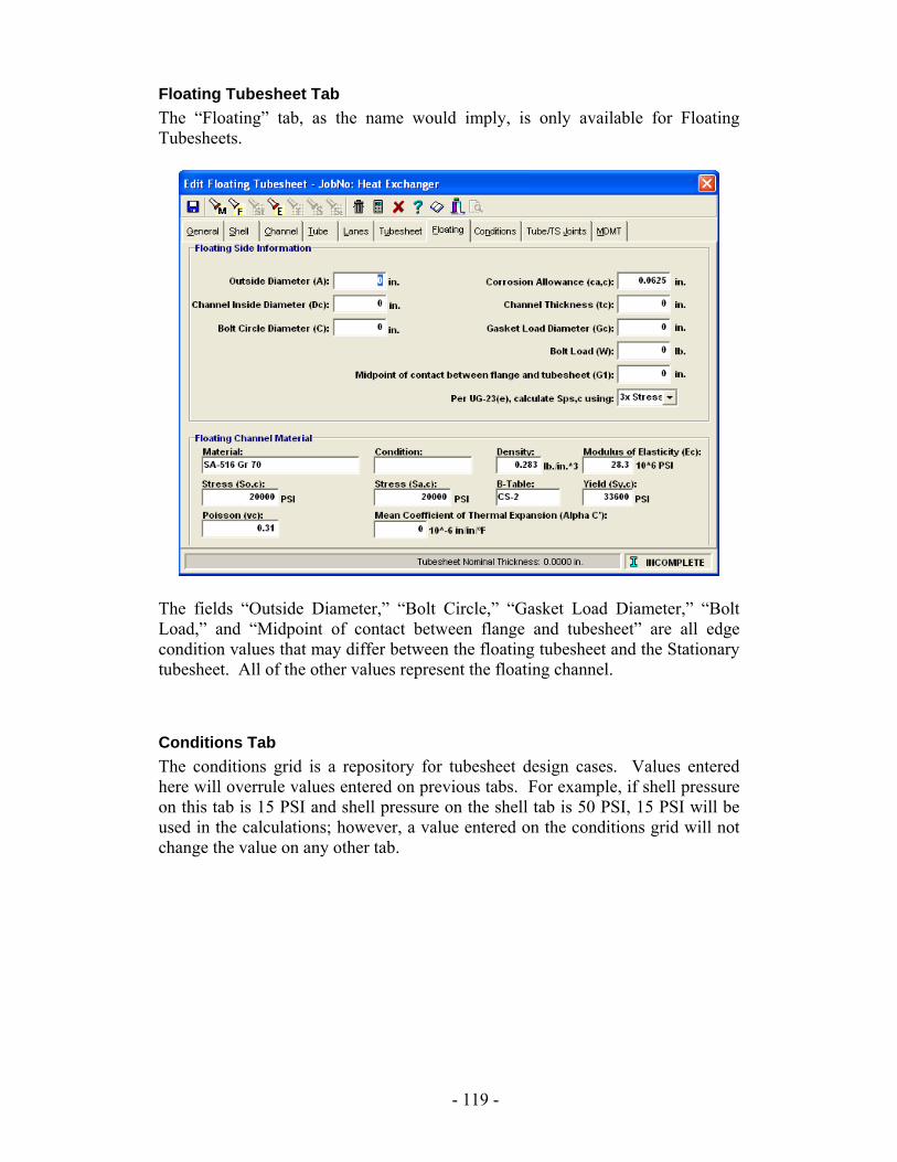
Floating Tubesheet Tab The “Floating” tab, as the name would imply, is only available for Floating Tubesheets.
The fields “Outside Diameter,” “Bolt Circle,” “Gasket Load Diameter,” “Bolt Load,” and “Midpoint of contact between flange and tubesheet” are all edge condition values that may differ between the floating tubesheet and the Stationary tubesheet. All of the other values represent the floating channel.
Conditions Tab The conditions grid is a repository for tubesheet design cases. Values entered here will overrule values entered on previous tabs. For example, if shell pressure on this tab is 15 PSI and shell pressure on the shell tab is 50 PSI, 15 PSI will be used in the calculations; however, a value entered on the conditions grid will not change the value on any other tab.
- 119 -
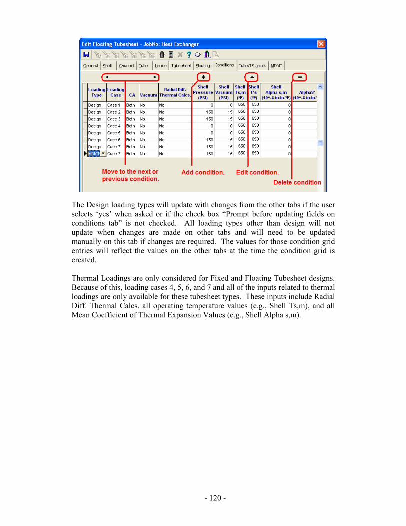
The Design loading types will update with changes from the other tabs if the user selects ‘yes’ when asked or if the check box “Prompt before updating fields on conditions tab” is not checked. All loading types other than design will not update when changes are made on other tabs and will need to be updated manually on this tab if changes are required. The values for those condition grid entries will reflect the values on the other tabs at the time the condition grid is created. Thermal Loadings are only considered for Fixed and Floating Tubesheet designs. Because of this, loading cases 4, 5, 6, and 7 and all of the inputs related to thermal loadings are only available for these tubesheet types. These inputs include Radial Diff. Thermal Calcs, all operating temperature values (e.g., Shell Ts,m), and all Mean Coefficient of Thermal Expansion Values (e.g., Shell Alpha s,m).
- 120 -
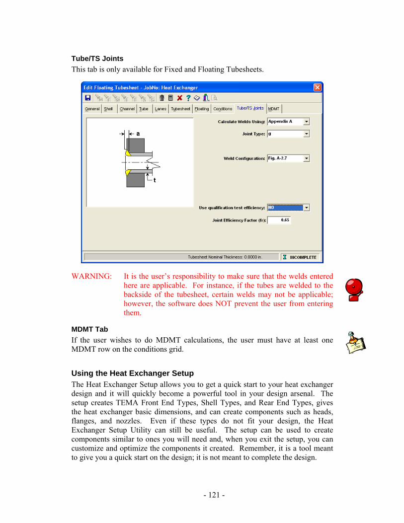
Tube/TS Joints This tab is only available for Fixed and Floating Tubesheets.
WARNING: It is the user’s responsibility to make sure that the welds entered here are applicable. For instance, if the tubes are welded to the backside of the tubesheet, certain welds may not be applicable; however, the software does NOT prevent the user from entering them.
MDMT Tab If the user wishes to do MDMT calculations, the user must have at least one MDMT row on the conditions grid.
Using the Heat Exchanger Setup The Heat Exchanger Setup allows you to get a quick start to your heat exchanger design and it will quickly become a powerful tool in your design arsenal. The setup creates TEMA Front End Types, Shell Types, and Rear End Types, gives the heat exchanger basic dimensions, and can create components such as heads, flanges, and nozzles. Even if these types do not fit your design, the Heat Exchanger Setup Utility can still be useful. The setup can be used to create components similar to ones you will need and, when you exit the setup, you can customize and optimize the components it created. Remember, it is a tool meant to give you a quick start on the design; it is not meant to complete the design.
- 121 -
The “Front End,” “Shell Type,” and “Rear End” screens are interconnected, and certain field selections on one screen may limit selections on another. For example, entering a fixed tubesheet configuration in the Tubesheet field on the front end will lock out the tubesheet field on the rear end because the tubesheets must be identical in the case of a fixed tubesheet. Likewise, certain selections on a screen may limit other selections on that same screen. If, in the first screen, “None” was selected for Nozzle, then the fields “Nozzle Quantity,” “Nozzle Diameter,” and “Nozzle Thickness” under Shell and Blind Flange would not be available. The following progression of screen shots are used to design a hypothetical vessel. The fourth screen shot is the component tree created from these inputs before the components were customized or altered.
Tip
The bolt browser is available on the Front End and Rear End screens to choose the bolt sizes. It can be opened four different ways.
1. Selecting the bolt browser icon, 2. Entering a value for the number of bolts, 3. Pressing Ctrl + B, 4. Right clicking and selecting it from the menu.
- 122 -
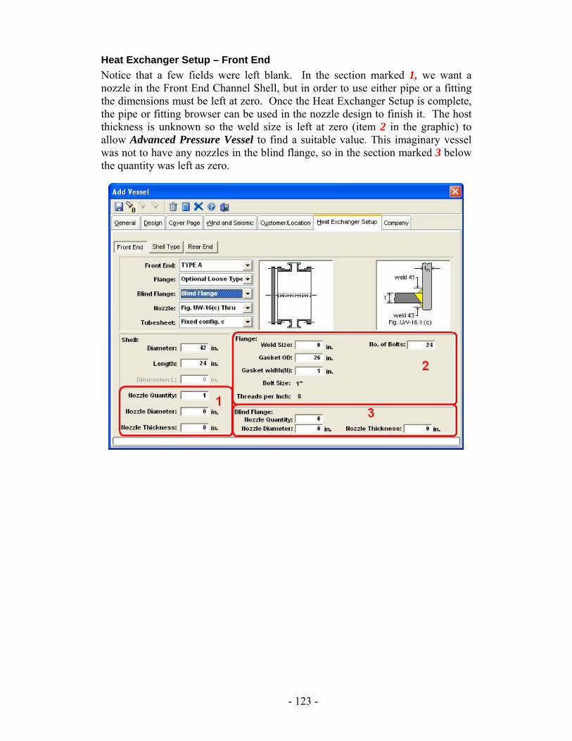
Heat Exchanger Setup – Front End Notice that a few fields were left blank. In the section marked 1, we want a nozzle in the Front End Channel Shell, but in order to use either pipe or a fitting the dimensions must be left at zero. Once the Heat Exchanger Setup is complete, the pipe or fitting browser can be used in the nozzle design to finish it. The host thickness is unknown so the weld size is left at zero (item 2 in the graphic) to allow Advanced Pressure Vessel to find a suitable value. This imaginary vessel was not to have any nozzles in the blind flange, so in the section marked 3 below the quantity was left as zero.
- 123 -
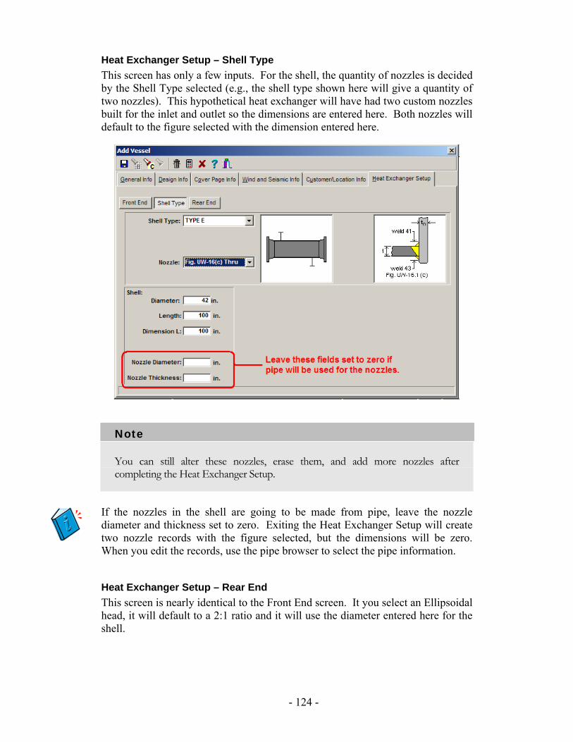
Heat Exchanger Setup – Shell Type This screen has only a few inputs. For the shell, the quantity of nozzles is decided by the Shell Type selected (e.g., the shell type shown here will give a quantity of two nozzles). This hypothetical heat exchanger will have had two custom nozzles built for the inlet and outlet so the dimensions are entered here. Both nozzles will default to the figure selected with the dimension entered here.
Note
You can still alter these nozzles, erase them, and add more nozzles after completing the Heat Exchanger Setup.
If the nozzles in the shell are going to be made from pipe, leave the nozzle diameter and thickness set to zero. Exiting the Heat Exchanger Setup will create two nozzle records with the figure selected, but the dimensions will be zero. When you edit the records, use the pipe browser to select the pipe information.
Heat Exchanger Setup – Rear End This screen is nearly identical to the Front End screen. It you select an Ellipsoidal head, it will default to a 2:1 ratio and it will use the diameter entered here for the shell.
- 124 -
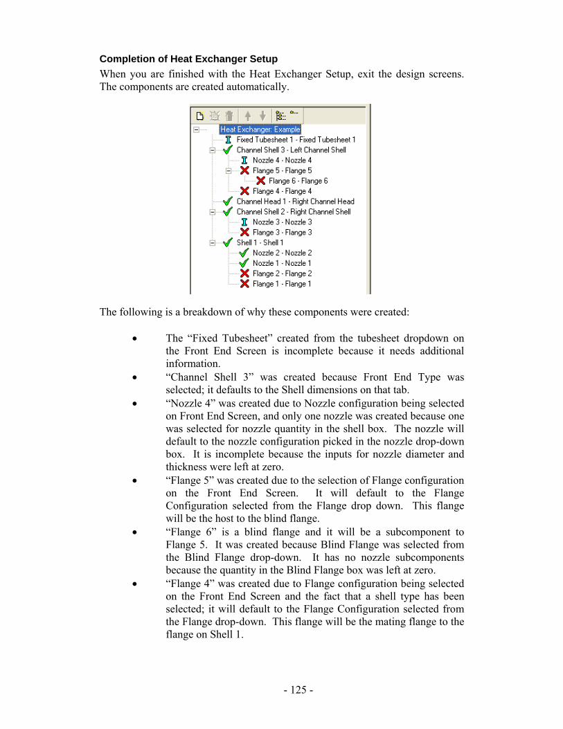
Completion of Heat Exchanger Setup When you are finished with the Heat Exchanger Setup, exit the design screens. The components are created automatically.
The following is a breakdown of why these components were created:
• The “Fixed Tubesheet” created from the tubesheet dropdown on the Front End Screen is incomplete because it needs additional information.
• “Channel Shell 3” was created because Front End Type was selected; it defaults to the Shell dimensions on that tab.
• “Nozzle 4” was created due to Nozzle configuration being selected on Front End Screen, and only one nozzle was created because one was selected for nozzle quantity in the shell box. The nozzle will default to the nozzle configuration picked in the nozzle drop-down box. It is incomplete because the inputs for nozzle diameter and thickness were left at zero.
• “Flange 5” was created due to the selection of Flange configuration on the Front End Screen. It will default to the Flange Configuration selected from the Flange drop down. This flange will be the host to the blind flange.
• “Flange 6” is a blind flange and it will be a subcomponent to Flange 5. It was created because Blind Flange was selected from the Blind Flange drop-down. It has no nozzle subcomponents because the quantity in the Blind Flange box was left at zero.
• “Flange 4” was created due to Flange configuration being selected on the Front End Screen and the fact that a shell type has been selected; it will default to the Flange Configuration selected from the Flange drop-down. This flange will be the mating flange to the flange on Shell 1.
- 125 -
• “Channel Head 1” was created because a head type was selected from the head drop-down on the rear end screen.
• “Channel Shell 2” was created due to Rear End Type being selected and will default to the Shell dimensions on that tab.
• “Nozzle 3” was created due to the selection of Nozzle configuration on the Rear End Screen. Only one nozzle was created because 1 was selected for nozzle quantity in the shell box; it is incomplete because the inputs for nozzle diameter and thickness were left at zero.
• “Flange 3” was created due to Flange configuration being selected on the rear End Screen and the fact that a shell type has been selected. It will default to the Flange Configuration selected from the Flange drop-down. This flange will be the mating flange to the flange on Shell 1.
• “Shell 1” was created because Shell Type was selected. It defaults to the Shell dimensions on that tab.
• “Nozzle 1” and “Nozzle 2” were created due to nozzle configuration being selected on the shell type screen; two nozzles were created because the shell type selected indicated 2 nozzles (i.e. inlet and outlet). These are identical to each other and default to the figure selected in the nozzle dropdown. These will be custom nozzles with the dimension defaulted to those in the shell box.
• “Flange 1” and “Flange 2” are flanges created to mate with Flange 3 and Flange 4 on the front and rear end channels.
You may add components or modify components as necessary. The Heat Exchanger Setup Utility is simply intended to be used as a tool to make designing a heat exchanger faster and easier.
- 126 -
Legs, Lugs, and Seismic Module The Legs, Lugs, and Seismic Module for Advanced Pressure Vessel enables you to design legs, lugs, and support rings for vertical vessels. This simple, yet powerful, tool will consider the forces and moments caused by a variety of factors: vessel material, liquid, packing, and insulation weight; wind and seismic loadings; attachment weights; bending due to eccentric attachments; and applied horizontal forces. The calculations are based on common industry methods that have been proven over and over, both in theory and in practice. The localized stresses at the leg-to-shell junction are found in the leg calculations using an approximate method. If a more accurate method is required, it will need to be performed outside of the leg calculations. If deemed acceptable, you may use the WRC-107 analysis in the software to perform these calculations. The leg calculations are limited to unbraced legs attached to the cylindrical shell of the vessel. Even though the software allows the user to cope out part of the leg to mold it to the head, it will not calculate the affect this has on the head. This also will not calculate localized stresses in the vessel caused by the leg if this is selected. The technical support staff and engineers at Computer Engineering may only provide support for designs within the limitations of the software and will not provide support or advice on how to use the software for designs outside this scope.
Suggested Design Procedure This manual is written to parallel the typical order in which the design of a vertical vessel supported by legs or lugs will be performed. Though this suggested procedure is not the required order, it is one that has proven to be very easy to use--even for designers new to the software. The following are the basic steps for designing leg or lug supports:
• Set defaults. • Set up basic design parameters for the vessel, such as pressure,
corrosion allowance, and wind and seismic codes. • Design the host components (heads, shells, and conical sections). • Design the sub-components (flanges, nozzles, and stiffening rings). • Design the supports (legs or lugs). • Add attachments, packing, liquid, and insulation; adjust wind load
diameters as needed. • Review reports and optimize design as needed.
- 127 -
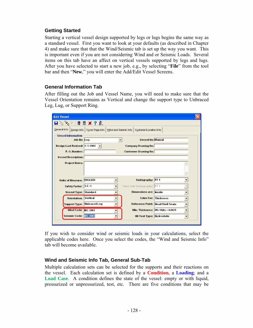
Getting Started Starting a vertical vessel design supported by legs or lugs begins the same way as a standard vessel. First you want to look at your defaults (as described in Chapter 4) and make sure that that the Wind/Seismic tab is set up the way you want. This is important even if you are not considering Wind and or Seismic Loads. Several items on this tab have an affect on vertical vessels supported by legs and lugs. After you have selected to start a new job, e.g., by selecting “File” from the tool bar and then “New,” you will enter the Add/Edit Vessel Screens.
General Information Tab After filling out the Job and Vessel Name, you will need to make sure that the Vessel Orientation remains as Vertical and change the support type to Unbraced Leg, Lug, or Support Ring.
If you wish to consider wind or seismic loads in your calculations, select the applicable codes here. Once you select the codes, the “Wind and Seismic Info” tab will become available.
Wind and Seismic Info Tab, General Sub-Tab Multiple calculation sets can be selected for the supports and their reactions on the vessel. Each calculation set is defined by a Condition, a Loading; and a Load Case. A condition defines the state of the vessel: empty or with liquid, pressurized or unpressurized, test, etc. There are five conditions that may be
- 128 -
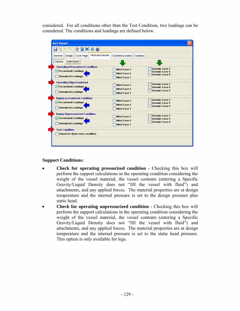
considered. For all conditions other than the Test Condition, two loadings can be considered. The conditions and loadings are defined below.
Support Conditions:
• Check for operating pressurized condition - Checking this box will perform the support calculations in the operating condition considering the weight of the vessel material, the vessel contents (entering a Specific Gravity/Liquid Density does not “fill the vessel with fluid”) and attachments, and any applied forces. The material properties are at design temperature and the internal pressure is set to the design pressure plus static head.
• Check for operating unpressurized condition - Checking this box will perform the support calculations in the operating condition considering the weight of the vessel material, the vessel contents (entering a Specific Gravity/Liquid Density does not “fill the vessel with fluid”) and attachments, and any applied forces. The material properties are at design temperature and the internal pressure is set to the static head pressure. This option is only available for legs.
- 129 -
• Check for empty pressurized condition – If this box is checked, the program will perform the support calculations in the empty condition considering the weight of the vessel material, attachments, and non-liquid contents, and any applied forces. The material properties are at design temperature and the internal pressure is set to the design pressure.
• Check for empty unpressurized condition - If this box is checked, the program will perform the support calculations in the empty condition considering the weight of the vessel material, attachments, and non-liquid contents, and any applied forces. The material properties are at design temperature and the internal pressure is set to zero.
• Check for Hydro test condition - Checking this box will perform the support calculations in the Hydro test condition considering the weight of the vessel flooded with water and any attachment weights and applied forces that are designated to be considered during the test. The material properties are at ambient temperature.
Loadings/Load Cases:
• Occasional – These are the wind and seismic loads that are calculated per the codes selected on the General Info tab in the Vessel screens. These loads will be added to those already considered per the conditions selected above. If selected in the defaults, these calculation sets will allow for an increase in allowable stresses.
• Sustained – These are the loads already considered per the conditions selected above. These calculation sets will not allow an increase in allowable stress.
Note: the appearance of the Load Case checkboxes is determined by the selection of the Occasional Loading checkbox.
- 130 -
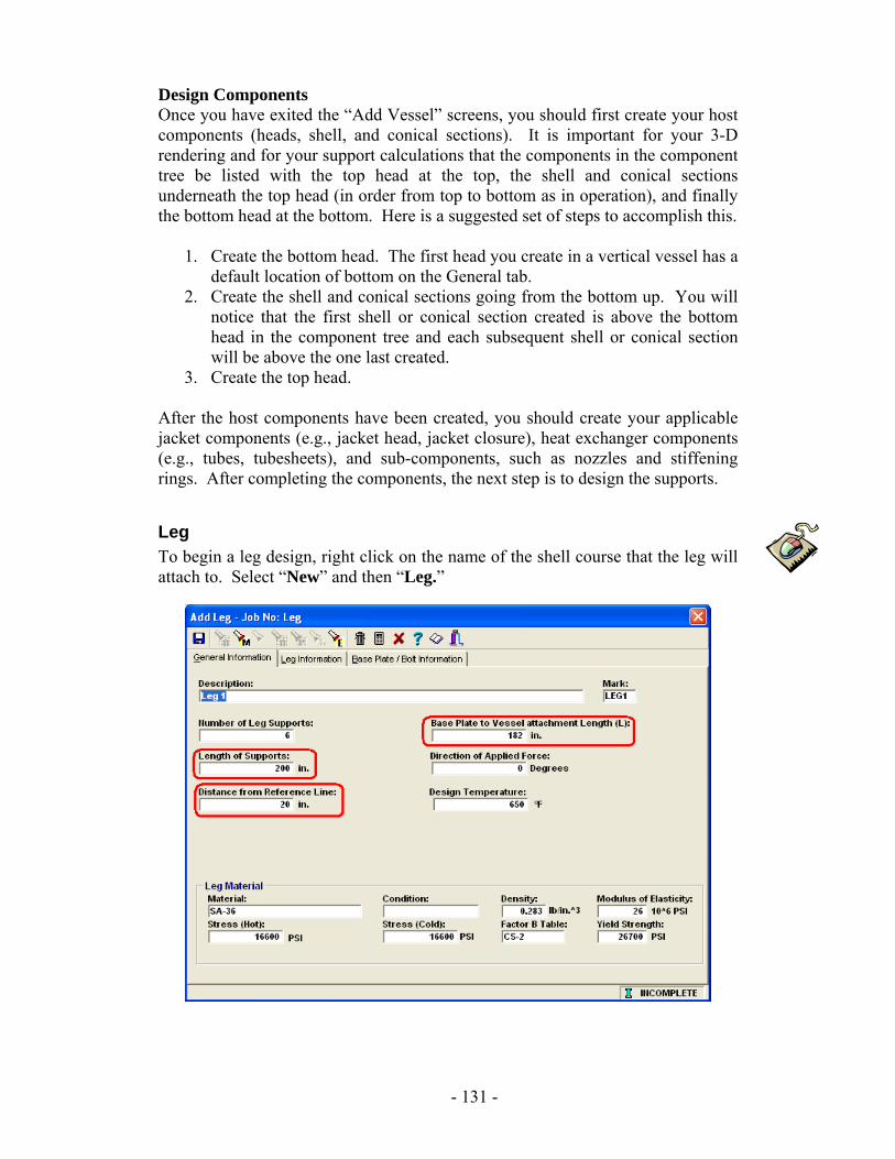
Design Components Once you have exited the “Add Vessel” screens, you should first create your host components (heads, shell, and conical sections). It is important for your 3-D rendering and for your support calculations that the components in the component tree be listed with the top head at the top, the shell and conical sections underneath the top head (in order from top to bottom as in operation), and finally the bottom head at the bottom. Here is a suggested set of steps to accomplish this.
1. Create the bottom head. The first head you create in a vertical vessel has a default location of bottom on the General tab.
2. Create the shell and conical sections going from the bottom up. You will notice that the first shell or conical section created is above the bottom head in the component tree and each subsequent shell or conical section will be above the one last created.
3. Create the top head. After the host components have been created, you should create your applicable jacket components (e.g., jacket head, jacket closure), heat exchanger components (e.g., tubes, tubesheets), and sub-components, such as nozzles and stiffening rings. After completing the components, the next step is to design the supports.
Leg To begin a leg design, right click on the name of the shell course that the leg will attach to. Select “New” and then “Leg.”
- 131 -
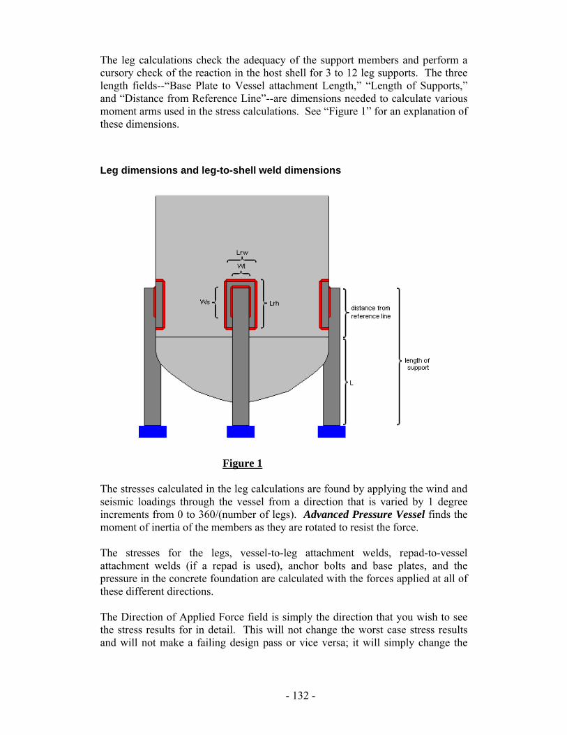
The leg calculations check the adequacy of the support members and perform a cursory check of the reaction in the host shell for 3 to 12 leg supports. The three length fields--“Base Plate to Vessel attachment Length,” “Length of Supports,” and “Distance from Reference Line”--are dimensions needed to calculate various moment arms used in the stress calculations. See “Figure 1” for an explanation of these dimensions.
Leg dimensions and leg-to-shell weld dimensions
Figure 1 The stresses calculated in the leg calculations are found by applying the wind and seismic loadings through the vessel from a direction that is varied by 1 degree increments from 0 to 360/(number of legs). Advanced Pressure Vessel finds the moment of inertia of the members as they are rotated to resist the force. The stresses for the legs, vessel-to-leg attachment welds, repad-to-vessel attachment welds (if a repad is used), anchor bolts and base plates, and the pressure in the concrete foundation are calculated with the forces applied at all of these different directions. The Direction of Applied Force field is simply the direction that you wish to see the stress results for in detail. This will not change the worst case stress results and will not make a failing design pass or vice versa; it will simply change the
- 132 -
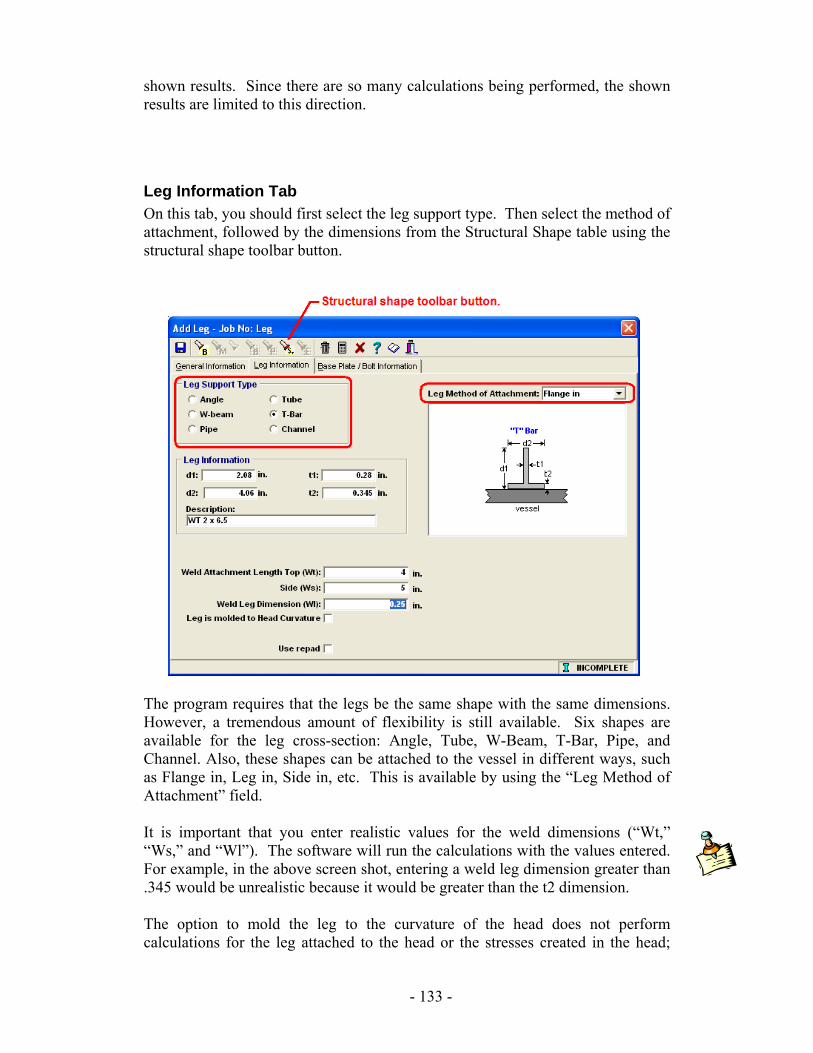
shown results. Since there are so many calculations being performed, the shown results are limited to this direction.
Leg Information Tab On this tab, you should first select the leg support type. Then select the method of attachment, followed by the dimensions from the Structural Shape table using the structural shape toolbar button.
The program requires that the legs be the same shape with the same dimensions. However, a tremendous amount of flexibility is still available. Six shapes are available for the leg cross-section: Angle, Tube, W-Beam, T-Bar, Pipe, and Channel. Also, these shapes can be attached to the vessel in different ways, such as Flange in, Leg in, Side in, etc. This is available by using the “Leg Method of Attachment” field. It is important that you enter realistic values for the weld dimensions (“Wt,” “Ws,” and “Wl”). The software will run the calculations with the values entered. For example, in the above screen shot, entering a weld leg dimension greater than .345 would be unrealistic because it would be greater than the t2 dimension. The option to mold the leg to the curvature of the head does not perform calculations for the leg attached to the head or the stresses created in the head;
- 133 -
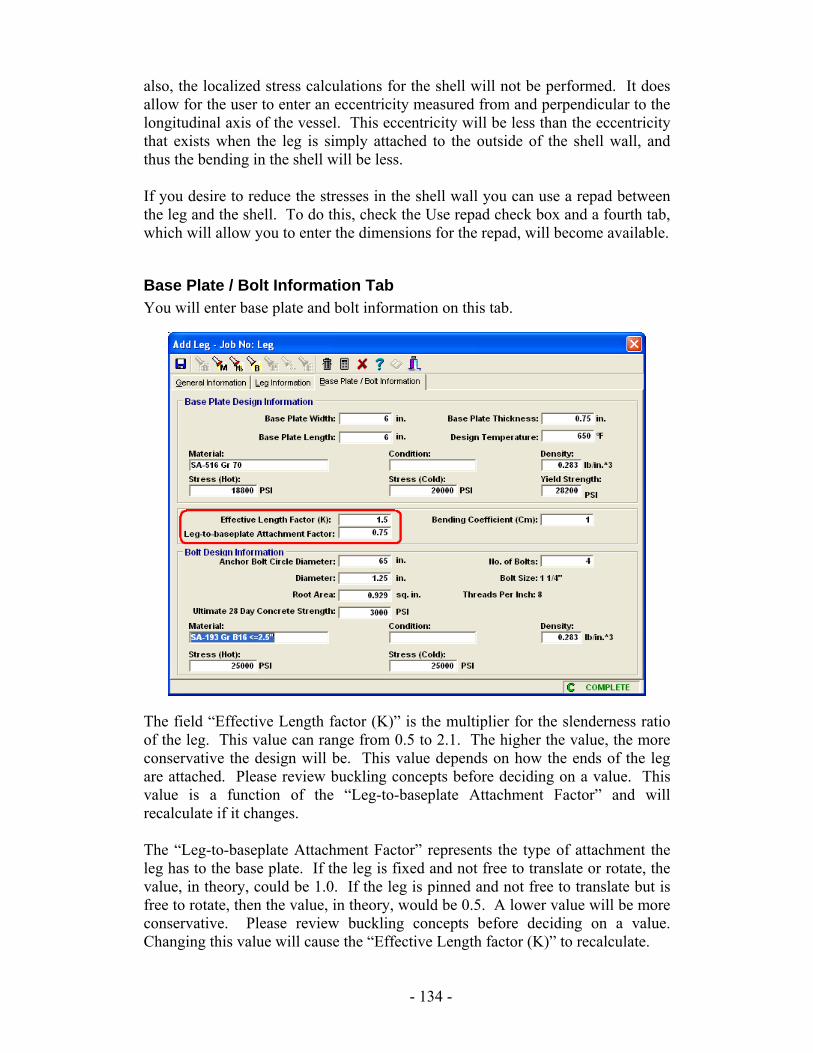
also, the localized stress calculations for the shell will not be performed. It does allow for the user to enter an eccentricity measured from and perpendicular to the longitudinal axis of the vessel. This eccentricity will be less than the eccentricity that exists when the leg is simply attached to the outside of the shell wall, and thus the bending in the shell will be less. If you desire to reduce the stresses in the shell wall you can use a repad between the leg and the shell. To do this, check the Use repad check box and a fourth tab, which will allow you to enter the dimensions for the repad, will become available.
Base Plate / Bolt Information Tab You will enter base plate and bolt information on this tab.
The field “Effective Length factor (K)” is the multiplier for the slenderness ratio of the leg. This value can range from 0.5 to 2.1. The higher the value, the more conservative the design will be. This value depends on how the ends of the leg are attached. Please review buckling concepts before deciding on a value. This value is a function of the “Leg-to-baseplate Attachment Factor” and will recalculate if it changes. The “Leg-to-baseplate Attachment Factor” represents the type of attachment the leg has to the base plate. If the leg is fixed and not free to translate or rotate, the value, in theory, could be 1.0. If the leg is pinned and not free to translate but is free to rotate, then the value, in theory, would be 0.5. A lower value will be more conservative. Please review buckling concepts before deciding on a value. Changing this value will cause the “Effective Length factor (K)” to recalculate.
- 134 -
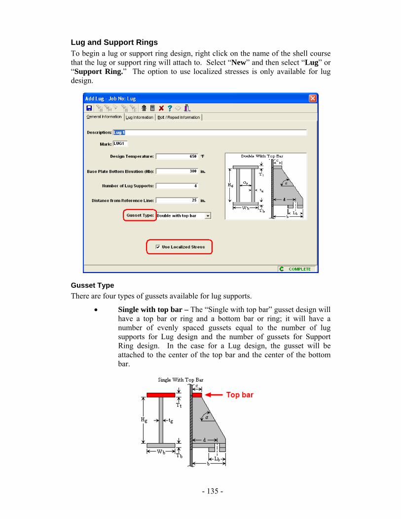
Lug and Support Rings To begin a lug or support ring design, right click on the name of the shell course that the lug or support ring will attach to. Select “New” and then select “Lug” or “Support Ring.” The option to use localized stresses is only available for lug design.
Gusset Type There are four types of gussets available for lug supports.
• Single with top bar – The “Single with top bar” gusset design will have a top bar or ring and a bottom bar or ring; it will have a number of evenly spaced gussets equal to the number of lug supports for Lug design and the number of gussets for Support Ring design. In the case for a Lug design, the gusset will be attached to the center of the top bar and the center of the bottom bar.
- 135 -
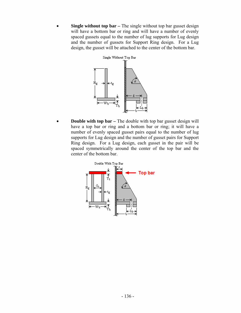
• Single without top bar – The single without top bar gusset design will have a bottom bar or ring and will have a number of evenly spaced gussets equal to the number of lug supports for Lug design and the number of gussets for Support Ring design. For a Lug design, the gusset will be attached to the center of the bottom bar.
• Double with top bar – The double with top bar gusset design will have a top bar or ring and a bottom bar or ring; it will have a number of evenly spaced gusset pairs equal to the number of lug supports for Lug design and the number of gusset pairs for Support Ring design. For a Lug design, each gusset in the pair will be spaced symmetrically around the center of the top bar and the center of the bottom bar.
- 136 -
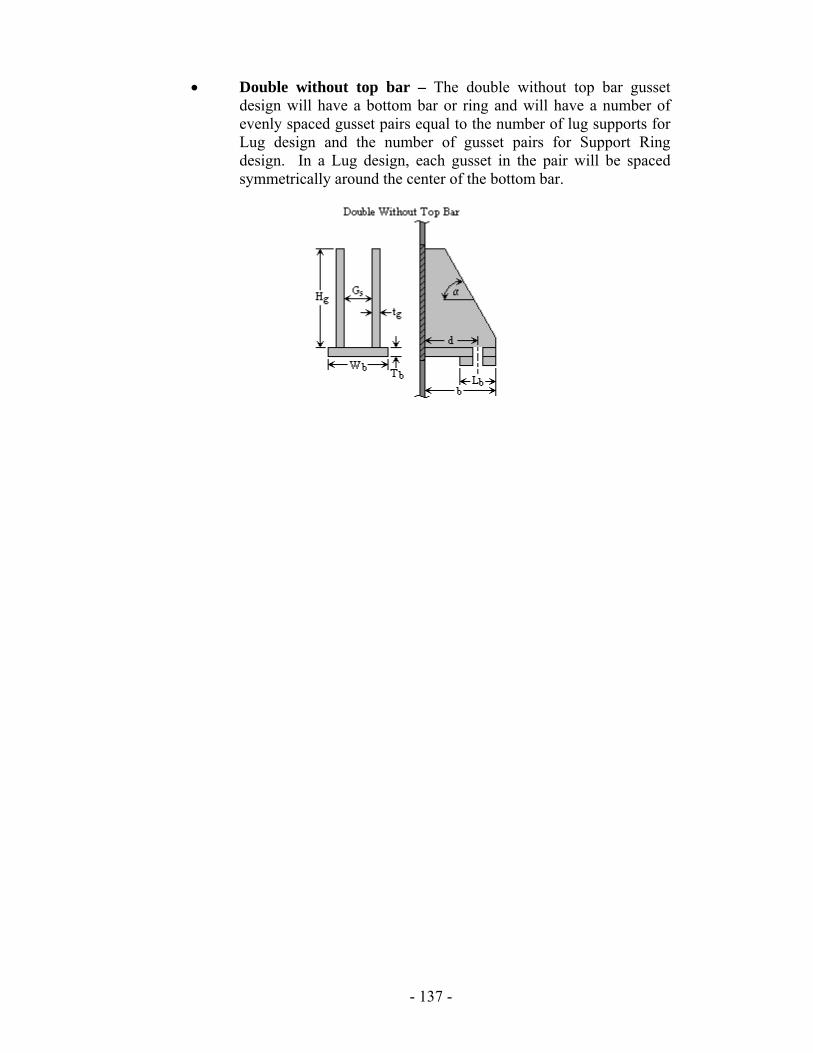
• Double without top bar – The double without top bar gusset design will have a bottom bar or ring and will have a number of evenly spaced gusset pairs equal to the number of lug supports for Lug design and the number of gusset pairs for Support Ring design. In a Lug design, each gusset in the pair will be spaced symmetrically around the center of the bottom bar.
- 137 -
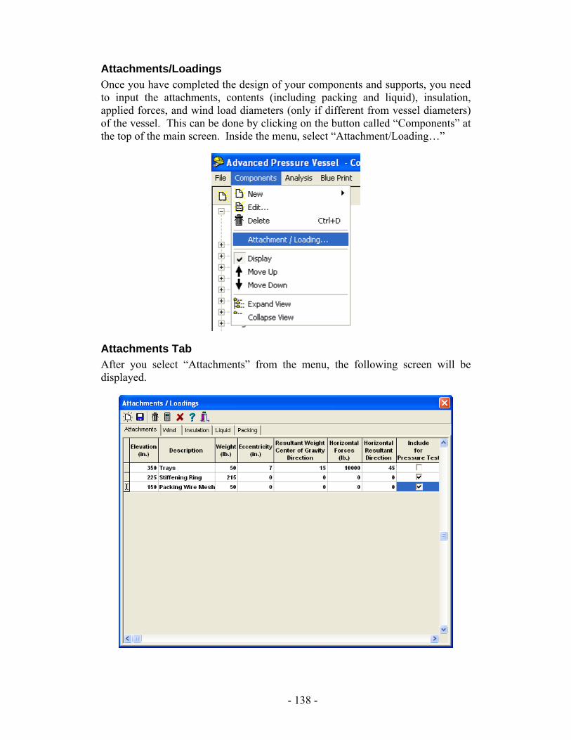
Attachments/Loadings Once you have completed the design of your components and supports, you need to input the attachments, contents (including packing and liquid), insulation, applied forces, and wind load diameters (only if different from vessel diameters) of the vessel. This can be done by clicking on the button called “Components” at the top of the main screen. Inside the menu, select “Attachment/Loading…”
Attachments Tab After you select “Attachments” from the menu, the following screen will be displayed.
- 138 -
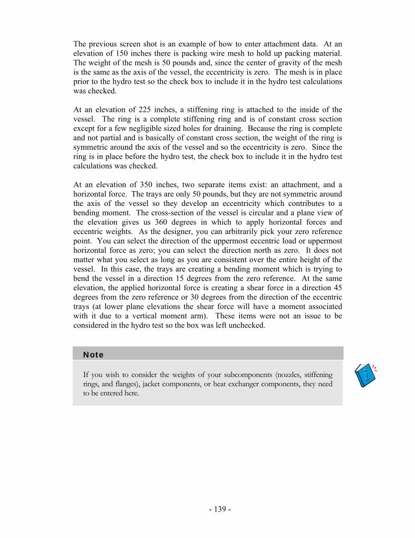
The previous screen shot is an example of how to enter attachment data. At an elevation of 150 inches there is packing wire mesh to hold up packing material. The weight of the mesh is 50 pounds and, since the center of gravity of the mesh is the same as the axis of the vessel, the eccentricity is zero. The mesh is in place prior to the hydro test so the check box to include it in the hydro test calculations was checked. At an elevation of 225 inches, a stiffening ring is attached to the inside of the vessel. The ring is a complete stiffening ring and is of constant cross section except for a few negligible sized holes for draining. Because the ring is complete and not partial and is basically of constant cross section, the weight of the ring is symmetric around the axis of the vessel and so the eccentricity is zero. Since the ring is in place before the hydro test, the check box to include it in the hydro test calculations was checked. At an elevation of 350 inches, two separate items exist: an attachment, and a horizontal force. The trays are only 50 pounds, but they are not symmetric around the axis of the vessel so they develop an eccentricity which contributes to a bending moment. The cross-section of the vessel is circular and a plane view of the elevation gives us 360 degrees in which to apply horizontal forces and eccentric weights. As the designer, you can arbitrarily pick your zero reference point. You can select the direction of the uppermost eccentric load or uppermost horizontal force as zero; you can select the direction north as zero. It does not matter what you select as long as you are consistent over the entire height of the vessel. In this case, the trays are creating a bending moment which is trying to bend the vessel in a direction 15 degrees from the zero reference. At the same elevation, the applied horizontal force is creating a shear force in a direction 45 degrees from the zero reference or 30 degrees from the direction of the eccentric trays (at lower plane elevations the shear force will have a moment associated with it due to a vertical moment arm). These items were not an issue to be considered in the hydro test so the box was left unchecked.
Note
If you wish to consider the weights of your subcomponents (nozzles, stiffening rings, and flanges), jacket components, or heat exchanger components, they need to be entered here.
- 139 -
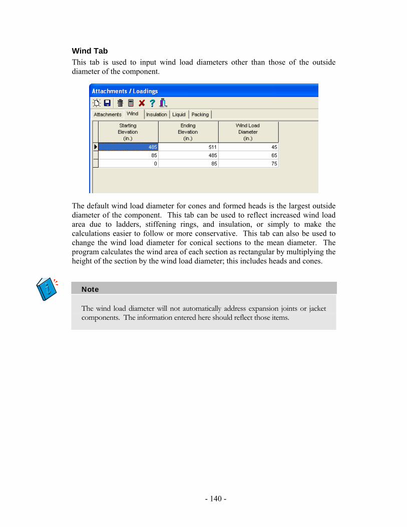
Wind Tab This tab is used to input wind load diameters other than those of the outside diameter of the component.
The default wind load diameter for cones and formed heads is the largest outside diameter of the component. This tab can be used to reflect increased wind load area due to ladders, stiffening rings, and insulation, or simply to make the calculations easier to follow or more conservative. This tab can also be used to change the wind load diameter for conical sections to the mean diameter. The program calculates the wind area of each section as rectangular by multiplying the height of the section by the wind load diameter; this includes heads and cones.
Note
The wind load diameter will not automatically address expansion joints or jacket components. The information entered here should reflect those items.
- 140 -
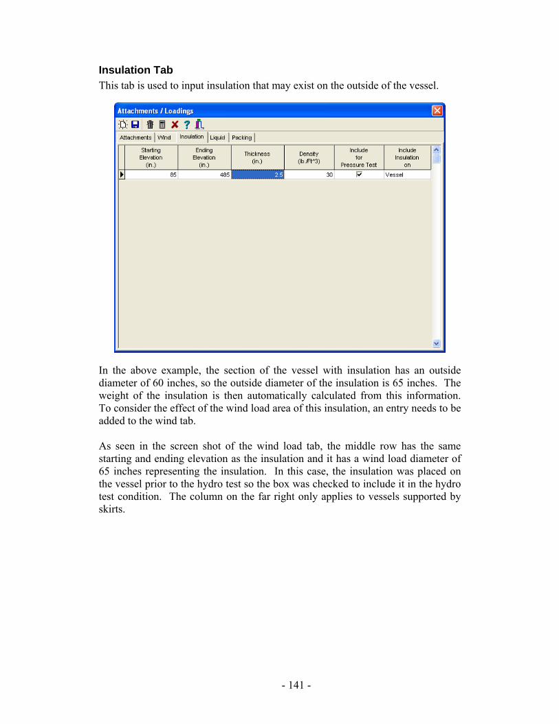
Insulation Tab This tab is used to input insulation that may exist on the outside of the vessel.
In the above example, the section of the vessel with insulation has an outside diameter of 60 inches, so the outside diameter of the insulation is 65 inches. The weight of the insulation is then automatically calculated from this information. To consider the effect of the wind load area of this insulation, an entry needs to be added to the wind tab. As seen in the screen shot of the wind load tab, the middle row has the same starting and ending elevation as the insulation and it has a wind load diameter of 65 inches representing the insulation. In this case, the insulation was placed on the vessel prior to the hydro test so the box was checked to include it in the hydro test condition. The column on the far right only applies to vessels supported by skirts.
- 141 -
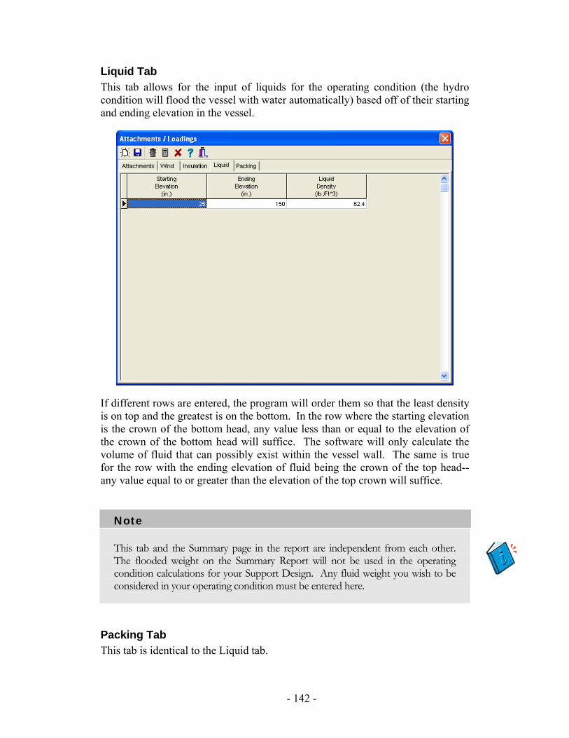
Liquid Tab This tab allows for the input of liquids for the operating condition (the hydro condition will flood the vessel with water automatically) based off of their starting and ending elevation in the vessel.
If different rows are entered, the program will order them so that the least density is on top and the greatest is on the bottom. In the row where the starting elevation is the crown of the bottom head, any value less than or equal to the elevation of the crown of the bottom head will suffice. The software will only calculate the volume of fluid that can possibly exist within the vessel wall. The same is true for the row with the ending elevation of fluid being the crown of the top head--any value equal to or greater than the elevation of the top crown will suffice.
Note
This tab and the Summary page in the report are independent from each other. The flooded weight on the Summary Report will not be used in the operating condition calculations for your Support Design. Any fluid weight you wish to be considered in your operating condition must be entered here.
Packing Tab This tab is identical to the Liquid tab.
- 142 -
Leg Methodology The leg methodology is the work of a professional engineering firm contracted to provide these calculations to Computer Engineering. The method used relies on many of today’s most popular vessel manuals, including AISC, Bednar, Megesy, and Moss. The calculations have been refined and perfected over time. This section provides a basic outline of the steps and calculations that Advanced Pressure Vessel performs to check the leg structures and vessel reactions for adequacy. They are provided here in a logical order reflective of the reports generated and mathematic calculations performed.
1. The Legs, Lugs, and Seismic Module determines the properties for the leg members by:
a. Calculating geometric properties of the leg cross-section with the x-axis of the cross section parallel to the vessel wall through the centroid of the cross-section and the y-axis normal to the vessel wall through the centroid of the cross section.
b. Calculating the allowable compressive stress for the leg. c. Calculating the allowable bending stress for the leg. d. Calculating allowable tensile stress for the leg. e. Calculating leg-to-vessel weld properties. f. Calculating repad-to-vessel weld properties if a repad is used.
2. The Legs, Lugs, and Seismic Module determines wind loading by: a. Calculating the wind center of gravity for the vessel. b. Calculating the wind pressure at the elevation of the wind center of
gravity based on the wind code selected. c. Calculating the wind force on the vessel based on the wind code
selected. 3. The Legs, Lugs, and Seismic Module determines seismic loading by:
a. Calculating the seismic center of gravity for the vessel. b. Calculating the seismic force on the vessel based on the seismic
code selected. c. Calculating a seismic force at top of vessel if required by seismic
code. 4. The Legs, Lugs, and Seismic Module performs leg member stress
calculations by: a. Applying wind and seismic loads through their center of gravities
coming from the direction defined by the user. This will be done with each load independently from the other; they are NOT assumed to act simultaneously.
b. Calculating the moment of inertia of each leg cross-section around the axis perpendicular to the applied wind and seismic force.
c. Determining lateral force distribution for the legs.
- 143 -
d. Determining all unknown forces and moments on vessel and each leg by setting the sum of forces and moments to zero in the appropriate coordinates for the vessel and each leg.
e. Calculating the stresses in the legs using the forces and moments, leg-to-vessel attachment welds, repad-to-vessel attachment welds, base plates and anchor bolts, and concrete foundation.
f. Determining if the stresses are acceptable. g. Determining the worst case stress by incrementing the direction of
the applied wind and seismic loading on the vessel by 1 degree from 0 to 360/(number of legs) and repeating these steps.
5. The Legs, Lugs, and Seismic Module performs shell stress calculations by:
a. Calculating the maximum tensile stress in the shell.
( ) Stress Weight - Stress Pressure InternalBending WindBending, Seismicmax +
b. Calculating the maximum compressive stress in the shell.
( )[ ]Stress Weight Stress Pressure ExternalBending WindBending, Seismicmax ++−
c. Calculating the allowable tensile stress for the shell. d. Calculating the allowable compressive stress for the shell. e. Determining if the stresses are acceptable; if the max tensile stress
is less than the allowable tensile stress for the shell and the max compressive stress is less than the allowable compressive stress, then the shell design is acceptable.
- 144 -
Tower Module The Tower Design Module for Advanced Pressure Vessel enables you to design intermediate supports, skirts, and base plates for tall vertical vessels and perform a static tower analysis on the vessel. This simple, yet powerful, tool will consider the forces and moments caused by a variety of factors: vessel material, liquid, packing, and insulation weight; wind and seismic loadings; attachment weights; bending due to eccentric attachments; and applied horizontal forces. The calculations are based on common industry methods that have been proven, both in theory and practice.
Important Information The tower analysis stress and deflection calculations are based on static design methods and are not adequate for tall vertical vessels that are subject to wind-induced vibration. These vessels must be designed to meet static requirements and then be designed to withstand dynamic loading (wind-induced vibration) or redesigned to prevent it from occurring. Below is a suggested list of steps to determine if this needs to be considered and how to resolve it:
1. Design the tower for static loading (Advanced Tower Design). 2. Determine if vessel should be designed dynamically per an accepted
method such as the Freese Method, the Zorrilla Method, etc. 3. If the vessel satisfies the criteria of the method(s) used for not needing
dynamic analysis, and it satisfies your good engineering judgment, then the design is complete.
4. If the design requires Dynamic Analysis, decide whether to design the vessel to withstand dynamic loadings or to redesign the vessel to prevent them from occurring; if the former is chosen, then methods outside the scope of Advanced Tower Design must be used.
5. If the vessel is to be redesigned to prevent wind-induced vibration, consider the following methods as suggested by Dennis Moss in Pressure Vessel Design Manual:
a. Arrange external attachments to break vortices. b. Add external spoilers in a fashion to break vortices. c. Add linings to dampen vibration. d. Add bracing or guy wires. e. Redesign main vessel.
6. The adequacy of the methods in item 5 must be checked outside the software. If the main vessel is redesigned, then repeat these steps.
Note: The technical support staff and engineers at Computer Engineering will provide support for static designs within the limitations of the software and will not provide support on how to use the software for designs outside this scope.
- 145 -
Suggested Design Procedure This manual is written according to the typical order in which the design of a tall vertical vessel will be performed. Though this suggested procedure is not the required order, it is one that has proven to be very easy to use, even for designers new to the software. Listed below are the basic steps; the following sections will explain them in further detail:
1. Set defaults. 2. Set up basic design parameters for the vessel, such as pressure, corrosion
allowance, and wind and seismic codes. 3. Design the host components (heads, shells, and conical sections, including
channel components). 4. Design jacket components (if applicable). 5. Design tubes, tubesheets, and expansion joints (if applicable). 6. Design the sub-components (flanges, nozzles, and stiffening rings). 7. Design the intermediate supports and skirt. 8. Design the base plate. 9. Add attachments, packing, liquid, and insulation; adjust wind load
diameters as needed. 10. Review reports and optimize design as needed.
- 146 -
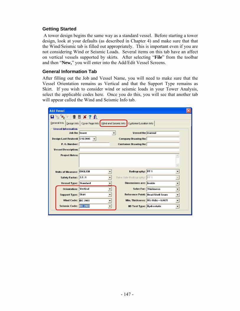
Getting Started A tower design begins the same way as a standard vessel. Before starting a tower design, look at your defaults (as described in Chapter 4) and make sure that that the Wind/Seismic tab is filled out appropriately. This is important even if you are not considering Wind or Seismic Loads. Several items on this tab have an affect on vertical vessels supported by skirts. After selecting “File” from the toolbar and then “New,” you will enter into the Add/Edit Vessel Screens.
General Information Tab After filling out the Job and Vessel Name, you will need to make sure that the Vessel Orientation remains as Vertical and that the Support Type remains as Skirt. If you wish to consider wind or seismic loads in your Tower Analysis, select the applicable codes here. Once you do this, you will see that another tab will appear called the Wind and Seismic Info tab.
- 147 -
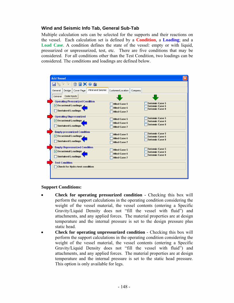
Wind and Seismic Info Tab, General Sub-Tab Multiple calculation sets can be selected for the supports and their reactions on the vessel. Each calculation set is defined by a Condition, a Loading; and a Load Case. A condition defines the state of the vessel: empty or with liquid, pressurized or unpressurized, test, etc. There are five conditions that may be considered. For all conditions other than the Test Condition, two loadings can be considered. The conditions and loadings are defined below.
Support Conditions:
• Check for operating pressurized condition - Checking this box will perform the support calculations in the operating condition considering the weight of the vessel material, the vessel contents (entering a Specific Gravity/Liquid Density does not “fill the vessel with fluid”) and attachments, and any applied forces. The material properties are at design temperature and the internal pressure is set to the design pressure plus static head.
• Check for operating unpressurized condition - Checking this box will perform the support calculations in the operating condition considering the weight of the vessel material, the vessel contents (entering a Specific Gravity/Liquid Density does not “fill the vessel with fluid”) and attachments, and any applied forces. The material properties are at design temperature and the internal pressure is set to the static head pressure. This option is only available for legs.
- 148 -
• Check for empty pressurized condition – If this box is checked, the program will perform the support calculations in the empty condition considering the weight of the vessel material, attachments, and non-liquid contents, and any applied forces. The material properties are at design temperature and the internal pressure is set to the design pressure.
• Check for empty unpressurized condition - If this box is checked, the program will perform the support calculations in the empty condition considering the weight of the vessel material, attachments, and non-liquid contents, and any applied forces. The material properties are at design temperature and the internal pressure is set to zero.
• Check for Hydro test condition - Checking this box will perform the support calculations in the Hydro test condition considering the weight of the vessel flooded with water, any attachment weights, and applied forces that are designated to be considered during the test. The material properties are at ambient temperature.
Loadings/Load Cases:
• Occasional – These are the wind and seismic loads that are calculated per the codes selected on the General Info tab in the Vessel screens. These loads will be added to those already considered per the conditions selected above. If selected in the defaults, these calculation sets will allow for an increase in allowable stresses.
• Sustained – These are the loads already considered per the conditions selected above. These calculation sets will not allow an increase in allowable stress.
Note: the appearance of the Load Case checkboxes is determined by the selection of the Occasional Loading checkbox.
Design Components After exiting the “Add Vessel” screens, you should create your host components (heads, shell, and conical sections). It is important for your 3-D rendering and for your tower calculations that the components in the component tree be listed with the top head at the top, the shell and conical sections underneath the top head (in order from top to bottom as in operation), and finally the bottom head at the bottom. The following is a suggested set of steps to accomplish this.
1. Create the bottom head. The first head you create in a vertical vessel has a default location of bottom on the General tab.
2. Create the shell and conical sections going from the bottom up. You will notice that the first shell or conical section created is above the bottom head in the component tree and each subsequent shell or conical section will be above the one last created.
3. Create the top head.
- 149 -

After you have created the host components, create jacket components, tubesheets, tubes, expansion joints, and sub-components, such as nozzles and stiffening rings. Vessel support (skirts, intermediate supports, and base plates) design will be explained below.
- 150 -
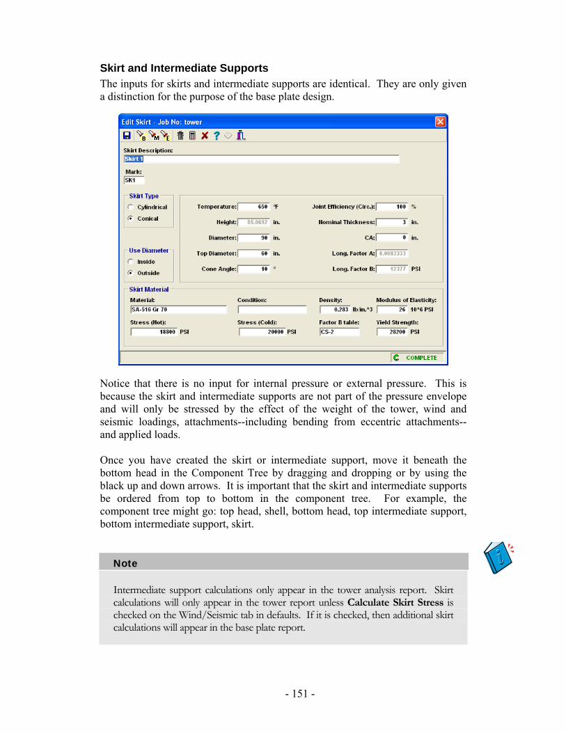
Skirt and Intermediate Supports The inputs for skirts and intermediate supports are identical. They are only given a distinction for the purpose of the base plate design.
Notice that there is no input for internal pressure or external pressure. This is because the skirt and intermediate supports are not part of the pressure envelope and will only be stressed by the effect of the weight of the tower, wind and seismic loadings, attachments--including bending from eccentric attachments--and applied loads. Once you have created the skirt or intermediate support, move it beneath the bottom head in the Component Tree by dragging and dropping or by using the black up and down arrows. It is important that the skirt and intermediate supports be ordered from top to bottom in the component tree. For example, the component tree might go: top head, shell, bottom head, top intermediate support, bottom intermediate support, skirt.
Note
Intermediate support calculations only appear in the tower analysis report. Skirt calculations will only appear in the tower report unless Calculate Skirt Stress is checked on the Wind/Seismic tab in defaults. If it is checked, then additional skirt calculations will appear in the base plate report.
- 151 -
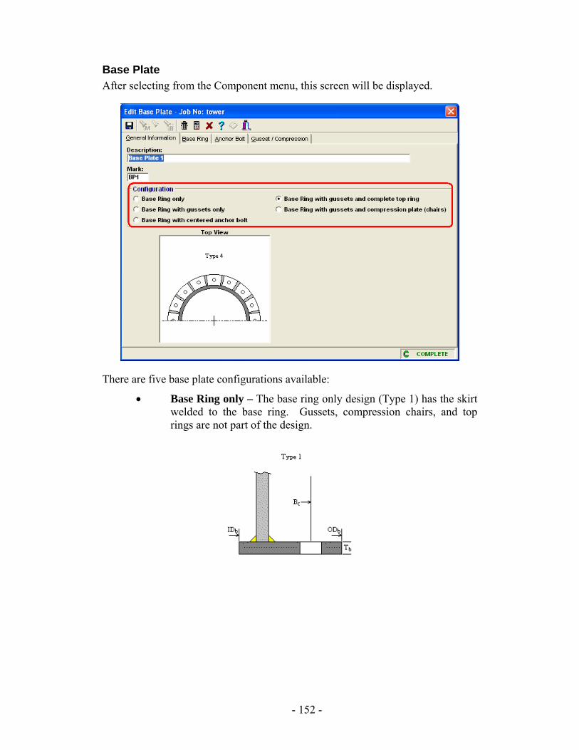
Base Plate After selecting from the Component menu, this screen will be displayed.
There are five base plate configurations available:
• Base Ring only – The base ring only design (Type 1) has the skirt welded to the base ring. Gussets, compression chairs, and top rings are not part of the design.
- 152 -
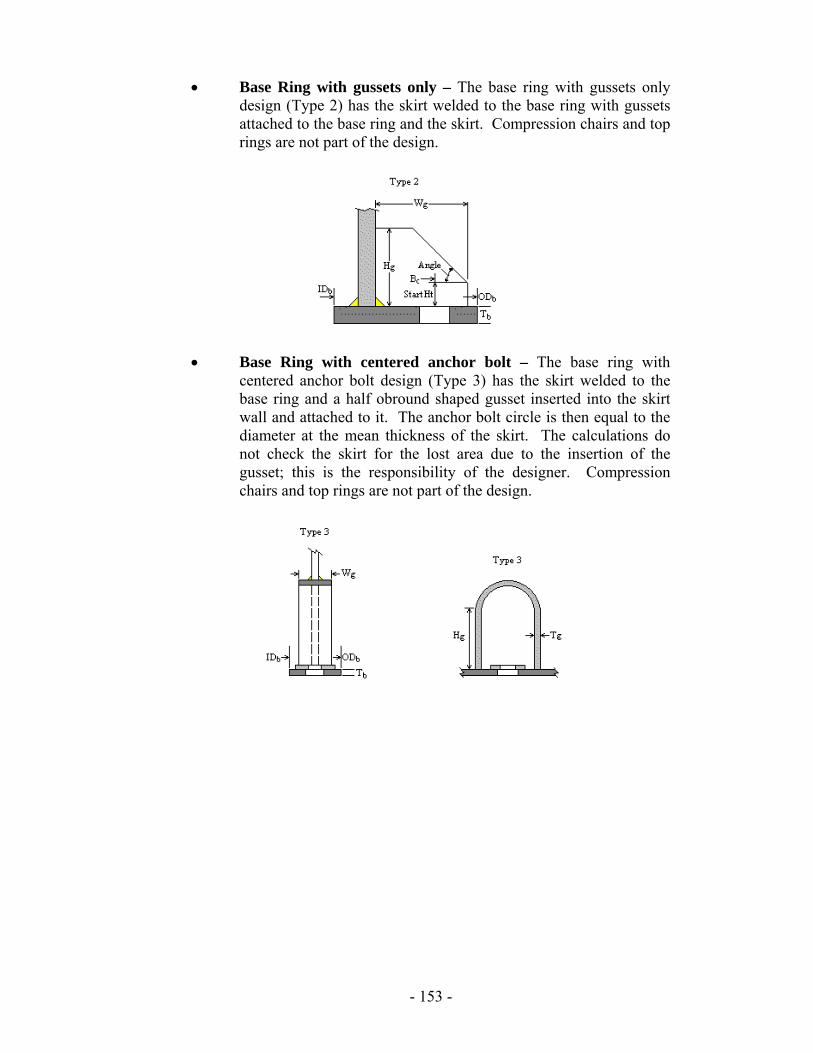
• Base Ring with gussets only – The base ring with gussets only design (Type 2) has the skirt welded to the base ring with gussets attached to the base ring and the skirt. Compression chairs and top rings are not part of the design.
• Base Ring with centered anchor bolt – The base ring with centered anchor bolt design (Type 3) has the skirt welded to the base ring and a half obround shaped gusset inserted into the skirt wall and attached to it. The anchor bolt circle is then equal to the diameter at the mean thickness of the skirt. The calculations do not check the skirt for the lost area due to the insertion of the gusset; this is the responsibility of the designer. Compression chairs and top rings are not part of the design.
- 153 -
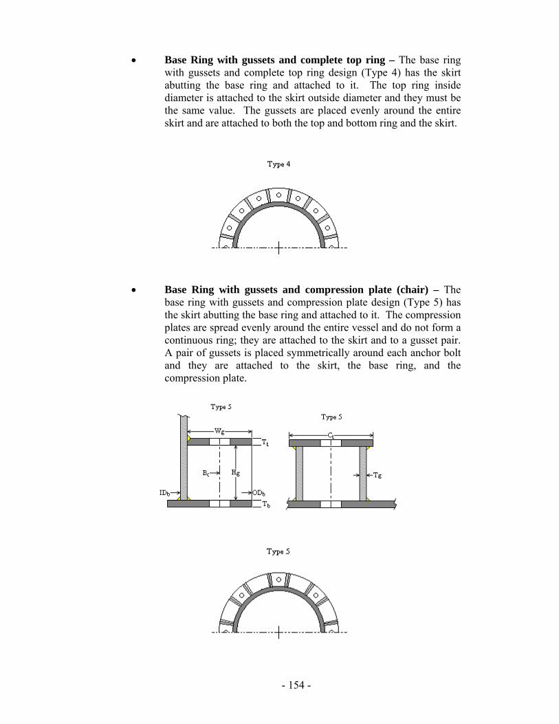
• Base Ring with gussets and complete top ring – The base ring with gussets and complete top ring design (Type 4) has the skirt abutting the base ring and attached to it. The top ring inside diameter is attached to the skirt outside diameter and they must be the same value. The gussets are placed evenly around the entire skirt and are attached to both the top and bottom ring and the skirt.
• Base Ring with gussets and compression plate (chair) – The
base ring with gussets and compression plate design (Type 5) has the skirt abutting the base ring and attached to it. The compression plates are spread evenly around the entire vessel and do not form a continuous ring; they are attached to the skirt and to a gusset pair. A pair of gussets is placed symmetrically around each anchor bolt and they are attached to the skirt, the base ring, and the compression plate.
- 154 -

Gusset / Compression Tab The Gusset/Compression tab will not be available for the “base ring only” design and many of the inputs are only visible if a certain configuration is chosen.
- 155 -
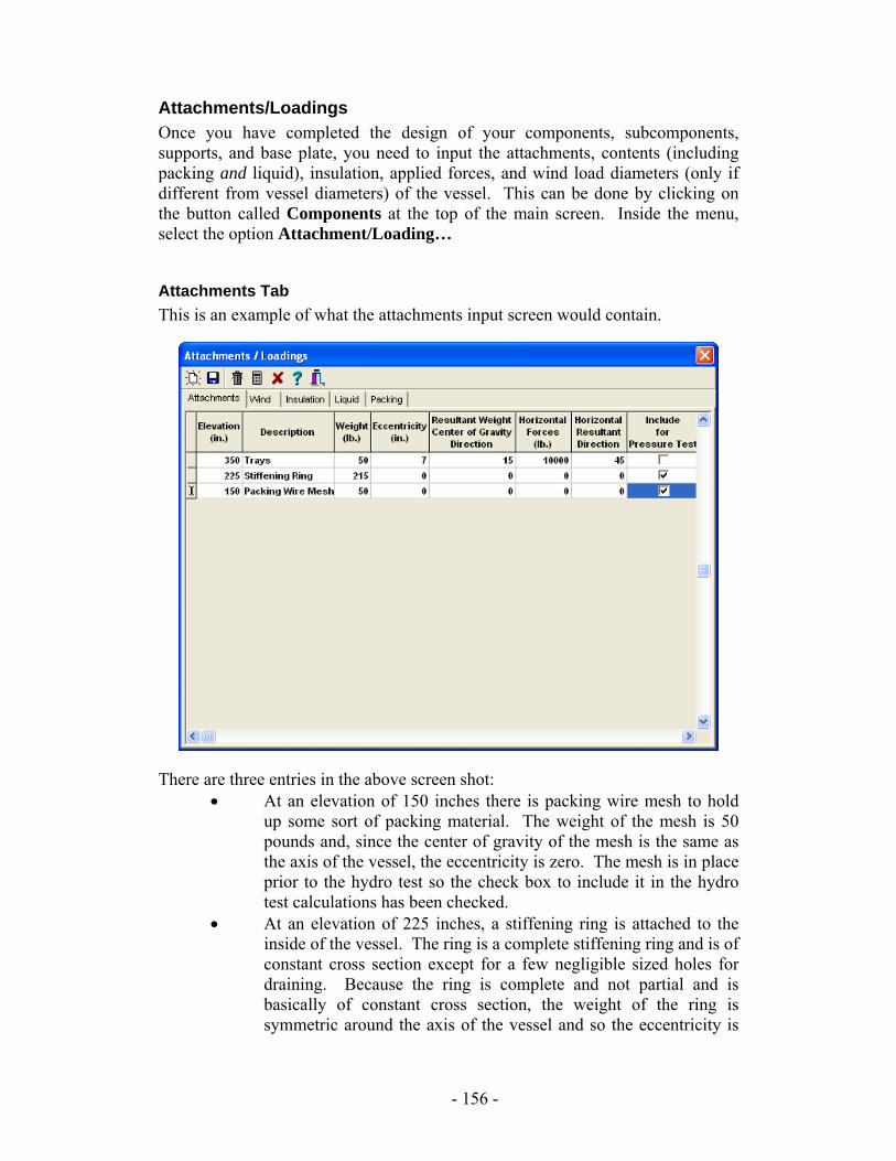
Attachments/Loadings Once you have completed the design of your components, subcomponents, supports, and base plate, you need to input the attachments, contents (including packing and liquid), insulation, applied forces, and wind load diameters (only if different from vessel diameters) of the vessel. This can be done by clicking on the button called Components at the top of the main screen. Inside the menu, select the option Attachment/Loading…
Attachments Tab This is an example of what the attachments input screen would contain.
There are three entries in the above screen shot: • At an elevation of 150 inches there is packing wire mesh to hold
up some sort of packing material. The weight of the mesh is 50 pounds and, since the center of gravity of the mesh is the same as the axis of the vessel, the eccentricity is zero. The mesh is in place prior to the hydro test so the check box to include it in the hydro test calculations has been checked.
• At an elevation of 225 inches, a stiffening ring is attached to the inside of the vessel. The ring is a complete stiffening ring and is of constant cross section except for a few negligible sized holes for draining. Because the ring is complete and not partial and is basically of constant cross section, the weight of the ring is symmetric around the axis of the vessel and so the eccentricity is
- 156 -
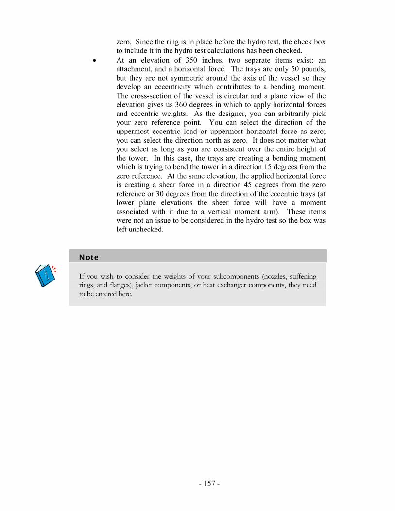
zero. Since the ring is in place before the hydro test, the check box to include it in the hydro test calculations has been checked.
• At an elevation of 350 inches, two separate items exist: an attachment, and a horizontal force. The trays are only 50 pounds, but they are not symmetric around the axis of the vessel so they develop an eccentricity which contributes to a bending moment. The cross-section of the vessel is circular and a plane view of the elevation gives us 360 degrees in which to apply horizontal forces and eccentric weights. As the designer, you can arbitrarily pick your zero reference point. You can select the direction of the uppermost eccentric load or uppermost horizontal force as zero; you can select the direction north as zero. It does not matter what you select as long as you are consistent over the entire height of the tower. In this case, the trays are creating a bending moment which is trying to bend the tower in a direction 15 degrees from the zero reference. At the same elevation, the applied horizontal force is creating a shear force in a direction 45 degrees from the zero reference or 30 degrees from the direction of the eccentric trays (at lower plane elevations the sheer force will have a moment associated with it due to a vertical moment arm). These items were not an issue to be considered in the hydro test so the box was left unchecked.
Note
If you wish to consider the weights of your subcomponents (nozzles, stiffening rings, and flanges), jacket components, or heat exchanger components, they need to be entered here.
- 157 -
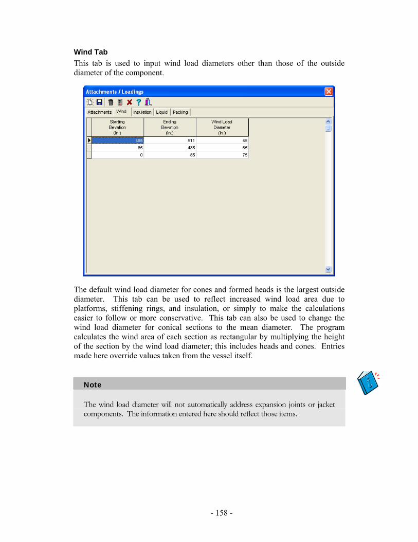
Wind Tab This tab is used to input wind load diameters other than those of the outside diameter of the component.
The default wind load diameter for cones and formed heads is the largest outside diameter. This tab can be used to reflect increased wind load area due to platforms, stiffening rings, and insulation, or simply to make the calculations easier to follow or more conservative. This tab can also be used to change the wind load diameter for conical sections to the mean diameter. The program calculates the wind area of each section as rectangular by multiplying the height of the section by the wind load diameter; this includes heads and cones. Entries made here override values taken from the vessel itself.
Note
The wind load diameter will not automatically address expansion joints or jacket components. The information entered here should reflect those items.
- 158 -
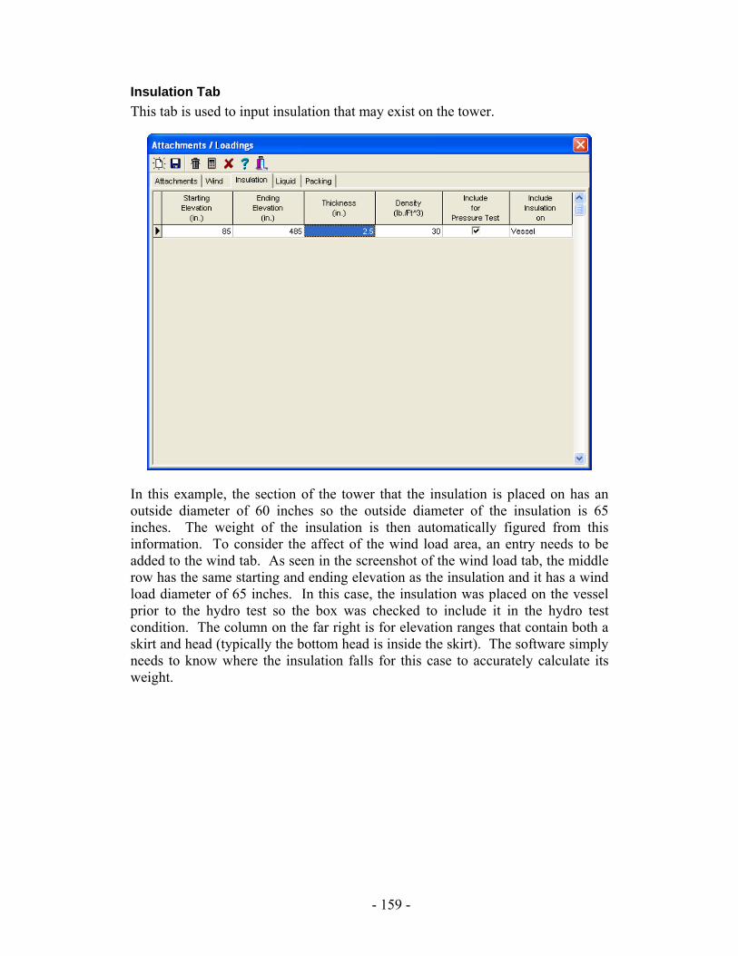
Insulation Tab This tab is used to input insulation that may exist on the tower.
In this example, the section of the tower that the insulation is placed on has an outside diameter of 60 inches so the outside diameter of the insulation is 65 inches. The weight of the insulation is then automatically figured from this information. To consider the affect of the wind load area, an entry needs to be added to the wind tab. As seen in the screenshot of the wind load tab, the middle row has the same starting and ending elevation as the insulation and it has a wind load diameter of 65 inches. In this case, the insulation was placed on the vessel prior to the hydro test so the box was checked to include it in the hydro test condition. The column on the far right is for elevation ranges that contain both a skirt and head (typically the bottom head is inside the skirt). The software simply needs to know where the insulation falls for this case to accurately calculate its weight.
- 159 -

Liquid Tab This tab allows for the input of liquids for the operating condition (the hydro condition will flood the vessel with water automatically) based off of their starting and ending elevation in the tower.
If different rows are entered, the software will order them so that the least density is on top and the greatest is on the bottom. In the row where the starting elevation is the crown of the bottom head, any value less than or equal to the elevation of the crown of the bottom head will suffice. Only the volume of liquid that can possibly exist within the vessel wall will be calculated. The same is true for the row with the ending elevation of fluid being the crown of the top head; any value equal to or greater than the elevation of the top crown will suffice.
Note
This tab and the Summary page in the report are independent from each other. The flooded weight on the Summary Report will not be used in the operating condition calculations for your Tower Analysis and Support Design. Any fluid weight you wish to be considered in your operating condition must be entered here.
Packing Tab This tab is identical to the Liquid tab.
- 160 -
Tower Analysis Basics Once you have completed the design section previously discussed, check to make sure your component order is correct one more time (top head, shells-cones, bottom head, skirt, base plate). Also check to make sure that your attachments, wind load diameters, liquid, insulation, and packing all match up with the correct elevations for the tower portions they are a part of. Advanced Pressure Vessel will automatically perform a Tower Analysis for you, incorporating all of these items. To see the Tower Analysis, go to Report and you will see a report called Tower Analysis. The base plate calculations will take information from the Tower Analysis; you can see this in the Base Plate report. Below is a basic introduction to the way that the Tower Analysis works.
Definitions Section – A section is a portion or length of the tower in which the general design parameters defined in Section Boundaries (below) are constant. Section Boundaries – A Section Boundary is an elevation where a change occurs in one or more of the following:
1. Section Type (e.g., head, cylindrical shell, conical section, skirt, etc.) 2. Design Pressure 3. Material Type 4. Inside Diameter 5. Nominal Wall Thickness 6. Corrosion Allowance 7. Insulation Thickness 8. Insulation Density 9. Liquid Density 10. Packing Density 11. Wind Load Diameter 12. Wind Pressure 13. Circumferential Weld Joint Efficiency
Segment – A segment is a section or a portion of a section used for calculation purposes. Node – A node exists at the top and bottom of every segment. Nodes are placed at section boundaries and at attachment locations.
- 161 -
Methodology The tower methodology is the work of a professional engineering firm contracted to provide these calculations to Computer Engineering. The method used relies on many of today’s popular vessel manuals, including AISC, Bednar, Megesy, and Moss. The calculations have been refined and perfected over time. This section provides a basic outline of the steps and calculations that the Tower Module performs to check the skirt and vessel reactions for adequacy. They are provided here in a logical order reflective of the report and mathematics.
1. The Tower Module determines properties for the tower components by: a. Dividing the vessel into sections and segments. b. Calculating the weight of each segment. c. Calculating First Natural Period of Vibration for the vessel per
Rayleigh’s Method.
2. The Tower Module determines wind loading by: a. Calculating the wind pressure at the midpoint of each segment
from the wind code chosen. b. Calculating the wind force on each segment. c. Calculating the moment at the bottom of each segment from the
shear at the top of the segment and the wind force on the segment. d. Calculating the bending stress at the bottom of each segment due
to the moment at the bottom of the segment.
3. The Tower Module determines seismic loading by: a. Calculating the total seismic shear force on the vessel based on the
seismic code selected. b. Calculating the seismic shear distribution based on the seismic
code selected. c. Calculating the moment at the bottom of each segment from the
shear at the top of the segment and the seismic shear on the segment.
d. Calculating the bending stress at the bottom of each segment due to the moment at the bottom of the segment.
4. The Tower Module determines sustained loadings by: a. Calculating the stress in each segment due to internal pressure. b. Calculating the stress in each segment due to external pressure. c. Calculating the stress at the bottom of each segment due to weight.
5. The Tower Module determines stress superposition by: a. Calculating the maximum tensile stress in each segment as: ( ) Stress Weight - Stress Pressure InternalBending WindBending, Seismicmax +
b. Calculating the maximum compressive stress in each segment as:
( )[ ]Stress Weight Stress Pressure ExternalBending WindBending, Seismicmax ++−
- 162 -

c. Calculating the allowable tensile stress for each segment. d. Calculating the allowable compressive stress for each segment. e. Calculating the critical buckling stress for each segment.
6. The Tower Module compares stresses: If the maximum tensile stress is less than the allowable tensile stress for each segment and the maximum compressive stress less than the smaller of the allowable compressive stress or the critical buckling stress, then the tower design is acceptable.
- 163 -
Zick, Saddles, & Seismic Module The Zick Saddles Seismic Module for Advanced Pressure Vessel enables you to design saddle supports for horizontal vessels and check the reactions caused in the vessel by the saddles. This simple, yet powerful, tool will consider the forces and loadings caused by vessel material and content weight, wind and seismic loadings, attachment weights, and applied forces in either the longitudinal, transverse, or some composite direction. The calculations are based on common industry methods that have been proven over and over again, both in theory and in practice. These include L.P. Zick’s Paper and the AISC manual along with other sources.
Important Information The Zick Analysis Calculations are based on the paper by L.P. Zick and variations included in later references. A common thread, however, in these references and the original paper is the following set of assumptions:
1. The vessel is horizontal. 2. The vessel consists basically of one cylindrical shell and two identical
heads. 3. The vessel is symmetric around the mid-span of the shell. 4. The vessel is symmetrically weighted; this includes attachment weights. 5. Moments caused by eccentric weights are not considered. 6. The vessel is supported by two, and only two, saddles. 7. The saddles are identical with the exception that one may be a sliding
saddle. 8. The saddle placement is symmetric around the mid-span of the shell.
With the addition of components like tubesheets, tubes, jackets, and other attachments, the ability to stay within the limitation of these assumptions becomes impossible for many designs; however, the need to check these stresses still exists. To allow for this, the following steps are provided as a guide to determine if the stresses are acceptable (albeit conservative).
1. On paper, sum the moments around the left saddle caused by weights (other than the weight of the left/right heads, shell, and contents), and the right saddle reaction (unknown at this point). Set this sum equal to zero and solve for the right saddle reaction due to these weights.
2. Sum the vertical forces caused by weights (other than the weight of the left/right heads, shell, and contents) and both saddle reactions. Solve for the left saddle reaction.
3. Take the greater of the two reactions and multiply it by two. 4. Go to the attachments-loadings screen and enter this number in the
attachment tab. Enter the description as something that will not cause confusion to those reading the report. Remember, the distance from reference line field is only for your reference and the value entered there is trivial.
- 164 -
Suggested Design Procedure This manual is written to parallel the typical order in which the design of a horizontal vessel supported by saddles will be performed. Though this suggested procedure is not the required order, it is one that has proven to be very easy to use, even for designers new to the software. The following are the basic steps for designing saddle supports:
• Set defaults • Set up basic design parameters for the vessel, such as pressure,
corrosion allowance, and wind and seismic codes. • Design the host components (heads and shells). • Design the sub-components (flanges, nozzles, and stiffening rings). • Design the saddles. • Add attachments and liquid; adjust wind load diameters as needed. • Review reports and optimize the design as needed.
- 165 -
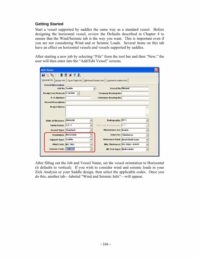
Getting Started Start a vessel supported by saddles the same way as a standard vessel. Before designing the horizontal vessel, review the Defaults described in Chapter 4 to ensure that the Wind/Seismic tab is the way you want. This is important even if you are not considering Wind and or Seismic Loads. Several items on this tab have an effect on horizontal vessels and vessels supported by saddles. After starting a new job by selecting “File” from the tool bar and then “New,” the user will then enter into the “Add/Edit Vessel” screens.
After filling out the Job and Vessel Name, set the vessel orientation to Horizontal (it defaults to vertical). If you wish to consider wind and seismic loads in your Zick Analysis or your Saddle design, then select the applicable codes. Once you do this, another tab—labeled “Wind and Seismic Info”—will appear.
- 166 -
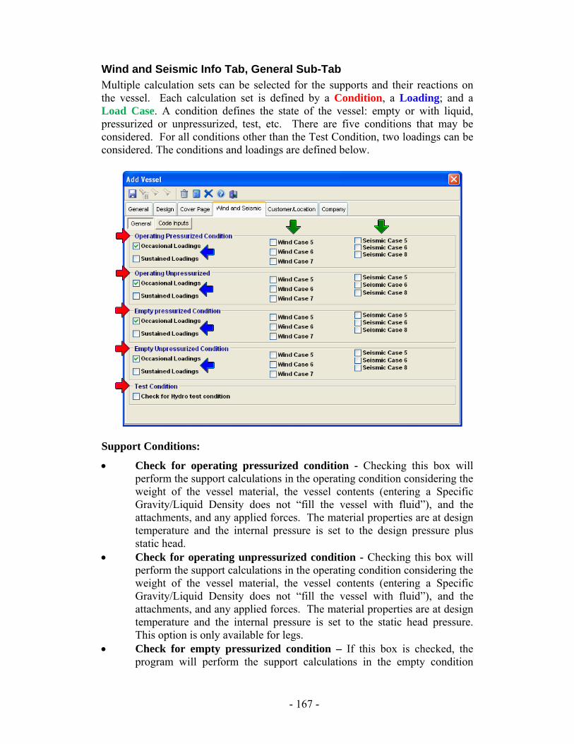
Wind and Seismic Info Tab, General Sub-Tab Multiple calculation sets can be selected for the supports and their reactions on the vessel. Each calculation set is defined by a Condition, a Loading; and a Load Case. A condition defines the state of the vessel: empty or with liquid, pressurized or unpressurized, test, etc. There are five conditions that may be considered. For all conditions other than the Test Condition, two loadings can be considered. The conditions and loadings are defined below.
Support Conditions:
• Check for operating pressurized condition - Checking this box will perform the support calculations in the operating condition considering the weight of the vessel material, the vessel contents (entering a Specific Gravity/Liquid Density does not “fill the vessel with fluid”), and the attachments, and any applied forces. The material properties are at design temperature and the internal pressure is set to the design pressure plus static head.
• Check for operating unpressurized condition - Checking this box will perform the support calculations in the operating condition considering the weight of the vessel material, the vessel contents (entering a Specific Gravity/Liquid Density does not “fill the vessel with fluid”), and the attachments, and any applied forces. The material properties are at design temperature and the internal pressure is set to the static head pressure. This option is only available for legs.
• Check for empty pressurized condition – If this box is checked, the program will perform the support calculations in the empty condition
- 167 -
considering the weight of the vessel material, attachments, and non-liquid contents, and any applied forces. The material properties are at design temperature and the internal pressure is set to the design pressure.
• Check for empty unpressurized condition - If this box is checked, the program will perform the support calculations in the empty condition considering the weight of the vessel material, attachments, and non-liquid contents, and any applied forces. The material properties are at design temperature and the internal pressure is set to zero.
• Check for Hydro test condition - Checking this box will perform the support calculations in the Hydro test condition considering the weight of the vessel flooded with water, and any attachment weights and applied forces that are designated to be considered during the test. The material properties are at ambient temperature.
Loadings/Load Cases:
• Occasional – These are the wind and seismic loads that are calculated per the codes selected on the General Info tab in the Vessel screens. These loads will be added to those already considered per the conditions selected above. If selected in the defaults, these calculation sets will allow for an increase in allowable stresses.
• Sustained – These are the loads already considered per the conditions selected above. These calculation sets will not allow an increase in allowable stress.
Note: the appearance of the Load Case checkboxes is determined by the selection of the Occasional Loading checkbox.
Design Components After exiting the “Add Vessel” screens, you should create host components (heads and shell). It is important for your 3-D rendering and for your saddle calculations that the components in the component tree be listed with the left head at the top, the shell underneath the left head, and finally the right head at the bottom. The following is a suggested set of steps to accomplish this.
1. Create the right head. The first head you create in a horizontal vessel has a default location of right on the General tab.
2. Create the shell. You will notice that the shell is created above the right head in the component tree.
3. Create the left head by returning to the right head design and clicking the copy button on the tool bar. You will notice that it will remain in the design screen but change the location to left on the General tab, and it will change the description to Head 2. If you exit the design now, you will have two identical heads and your components will be the correct order.
- 168 -

After the host components have been created, create sub-components such as nozzles and stiffening rings; this does not include your saddle design. The saddle design will allow you to design rings for use in the Zick Analysis.
- 169 -
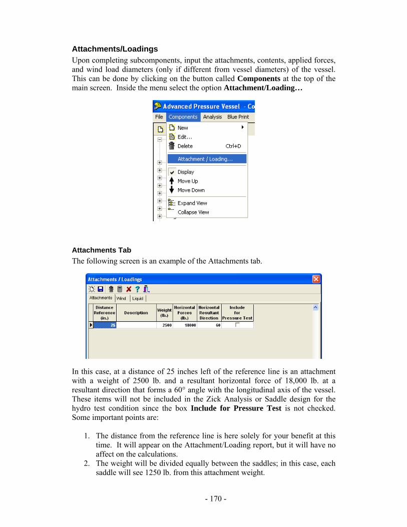
Attachments/Loadings Upon completing subcomponents, input the attachments, contents, applied forces, and wind load diameters (only if different from vessel diameters) of the vessel. This can be done by clicking on the button called Components at the top of the main screen. Inside the menu select the option Attachment/Loading…
Attachments Tab The following screen is an example of the Attachments tab.
In this case, at a distance of 25 inches left of the reference line is an attachment with a weight of 2500 lb. and a resultant horizontal force of 18,000 lb. at a resultant direction that forms a 60° angle with the longitudinal axis of the vessel. These items will not be included in the Zick Analysis or Saddle design for the hydro test condition since the box Include for Pressure Test is not checked. Some important points are:
1. The distance from the reference line is here solely for your benefit at this time. It will appear on the Attachment/Loading report, but it will have no affect on the calculations.
2. The weight will be divided equally between the saddles; in this case, each saddle will see 1250 lb. from this attachment weight.
- 170 -
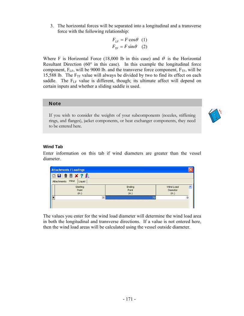
3. The horizontal forces will be separated into a longitudinal and a transverse force with the following relationship:
θcosFFLF = (1) θsinFFTF = (2) Where F is Horizontal Force (18,000 lb in this case) and θ is the Horizontal Resultant Direction (60° in this case). In this example the longitudinal force component, FLF, will be 9000 lb. and the transverse force component, FTF, will be 15,588 lb. The FTF value will always be divided by two to find its effect on each saddle. The FLF value is different, though; its ultimate affect will depend on certain inputs and whether a sliding saddle is used.
Note
If you wish to consider the weights of your subcomponents (nozzles, stiffening rings, and flanges), jacket components, or heat exchanger components, they need to be entered here.
Wind Tab Enter information on this tab if wind diameters are greater than the vessel diameter.
The values you enter for the wind load diameter will determine the wind load area in both the longitudinal and transverse directions. If a value is not entered here, then the wind load areas will be calculated using the vessel outside diameter.
- 171 -
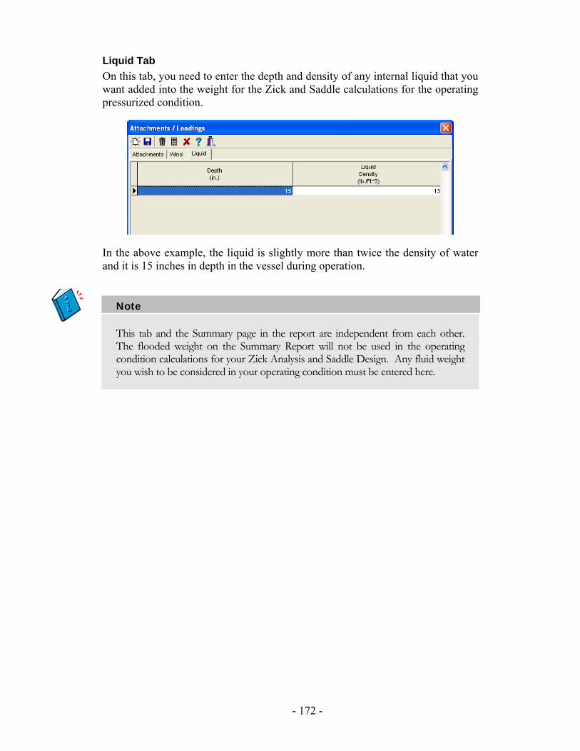
Liquid Tab On this tab, you need to enter the depth and density of any internal liquid that you want added into the weight for the Zick and Saddle calculations for the operating pressurized condition.
In the above example, the liquid is slightly more than twice the density of water and it is 15 inches in depth in the vessel during operation.
Note
This tab and the Summary page in the report are independent from each other. The flooded weight on the Summary Report will not be used in the operating condition calculations for your Zick Analysis and Saddle Design. Any fluid weight you wish to be considered in your operating condition must be entered here.
- 172 -
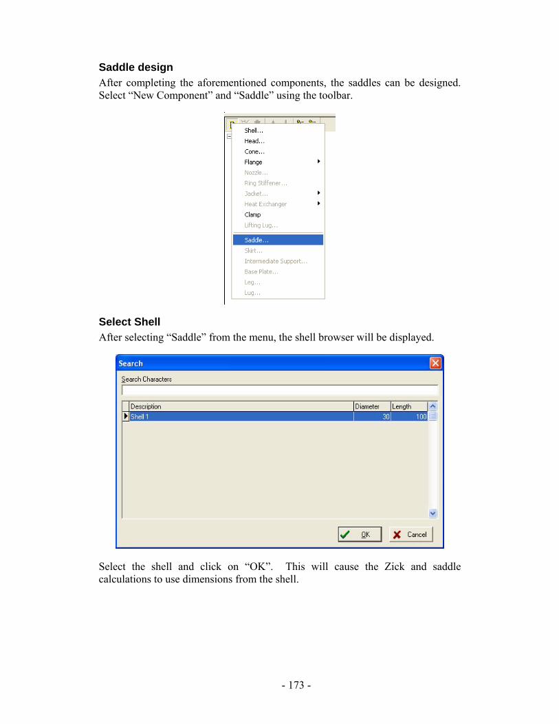
Saddle design After completing the aforementioned components, the saddles can be designed. Select “New Component” and “Saddle” using the toolbar.
Select Shell After selecting “Saddle” from the menu, the shell browser will be displayed.
Select the shell and click on “OK”. This will cause the Zick and saddle calculations to use dimensions from the shell.
- 173 -
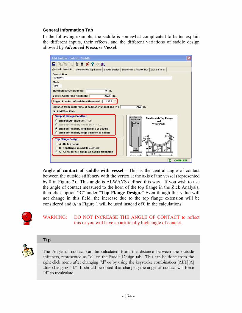
General Information Tab In the following example, the saddle is somewhat complicated to better explain the different inputs, their effects, and the different variations of saddle design allowed by Advanced Pressure Vessel.
Angle of contact of saddle with vessel - This is the central angle of contact between the outside stiffeners with the vertex at the axis of the vessel (represented by θ in Figure 2). This angle is ALWAYS defined this way. If you wish to use the angle of contact measured to the horn of the top flange in the Zick Analysis, then click option “C” under “Top Flange Design.” Even though this value will not change in this field, the increase due to the top flange extension will be considered and θf in Figure 1 will be used instead of θ in the calculations.
WARNING: DO NOT INCREASE THE ANGLE OF CONTACT to reflect this or you will have an artificially high angle of contact.
Tip
The Angle of contact can be calculated from the distance between the outside stiffeners, represented as “d” on the Saddle Design tab. This can be done from the right click menu after changing “d” or by using the keystroke combination [ALT][A] after changing “d.” It should be noted that changing the angle of contact will force “d” to recalculate.
- 174 -
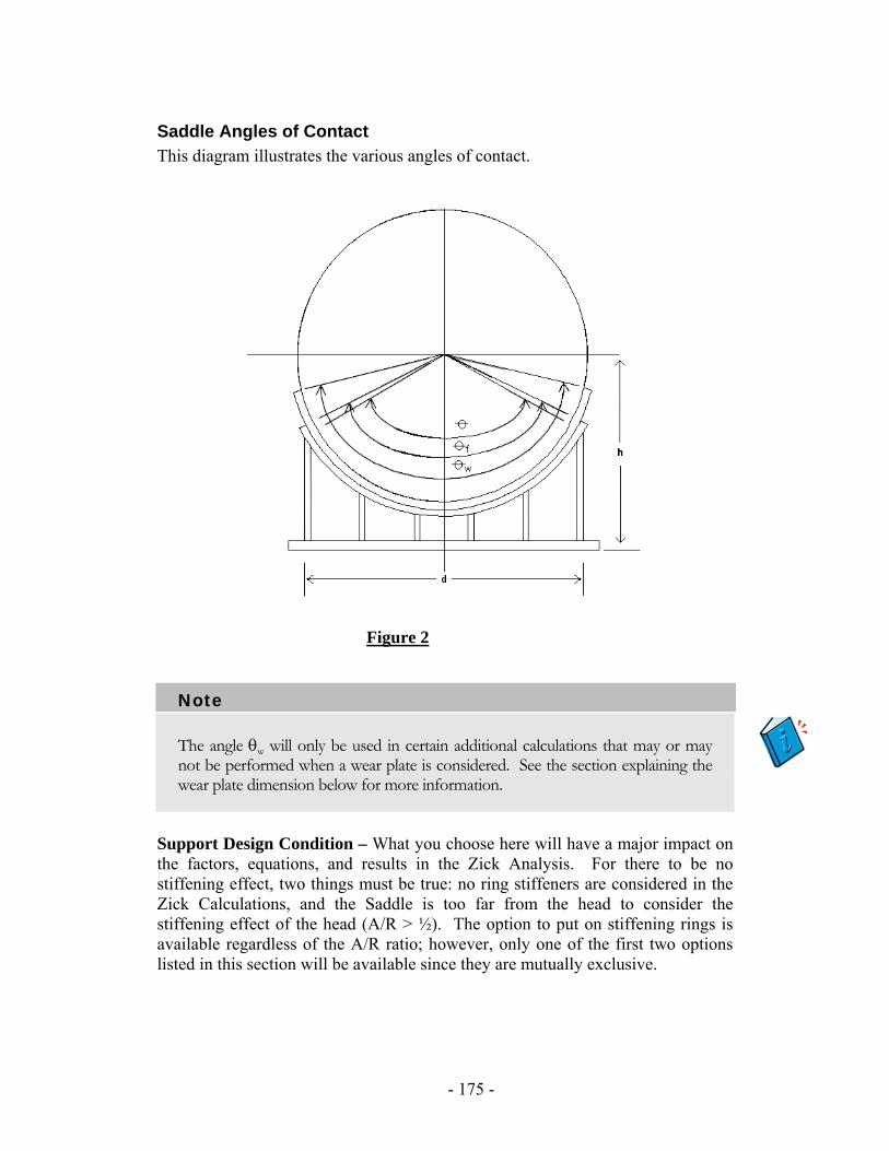
Saddle Angles of Contact This diagram illustrates the various angles of contact.
Figure 2
Note
The angle θw will only be used in certain additional calculations that may or may not be performed when a wear plate is considered. See the section explaining the wear plate dimension below for more information.
Support Design Condition – What you choose here will have a major impact on the factors, equations, and results in the Zick Analysis. For there to be no stiffening effect, two things must be true: no ring stiffeners are considered in the Zick Calculations, and the Saddle is too far from the head to consider the stiffening effect of the head (A/R > ½). The option to put on stiffening rings is available regardless of the A/R ratio; however, only one of the first two options listed in this section will be available since they are mutually exclusive.
- 175 -

Top Flange Design – The presence of a flange and its function are decided here. The option to consider the top flange as a saddle element, option “B,” will allow the saddle design to include a top flange; however, it will assume that the top flange extension (jf) is not rigid enough to allow the angle of contact for the Zick analysis to increase to the horn or the top flange. The option to consider the top flange as a saddle extension, option “C,” will allow the saddle design to include a top flange and it will use the angle measured to the horn of the flange as the angle of contact in the calculations. This will result in lower stresses.
- 176 -
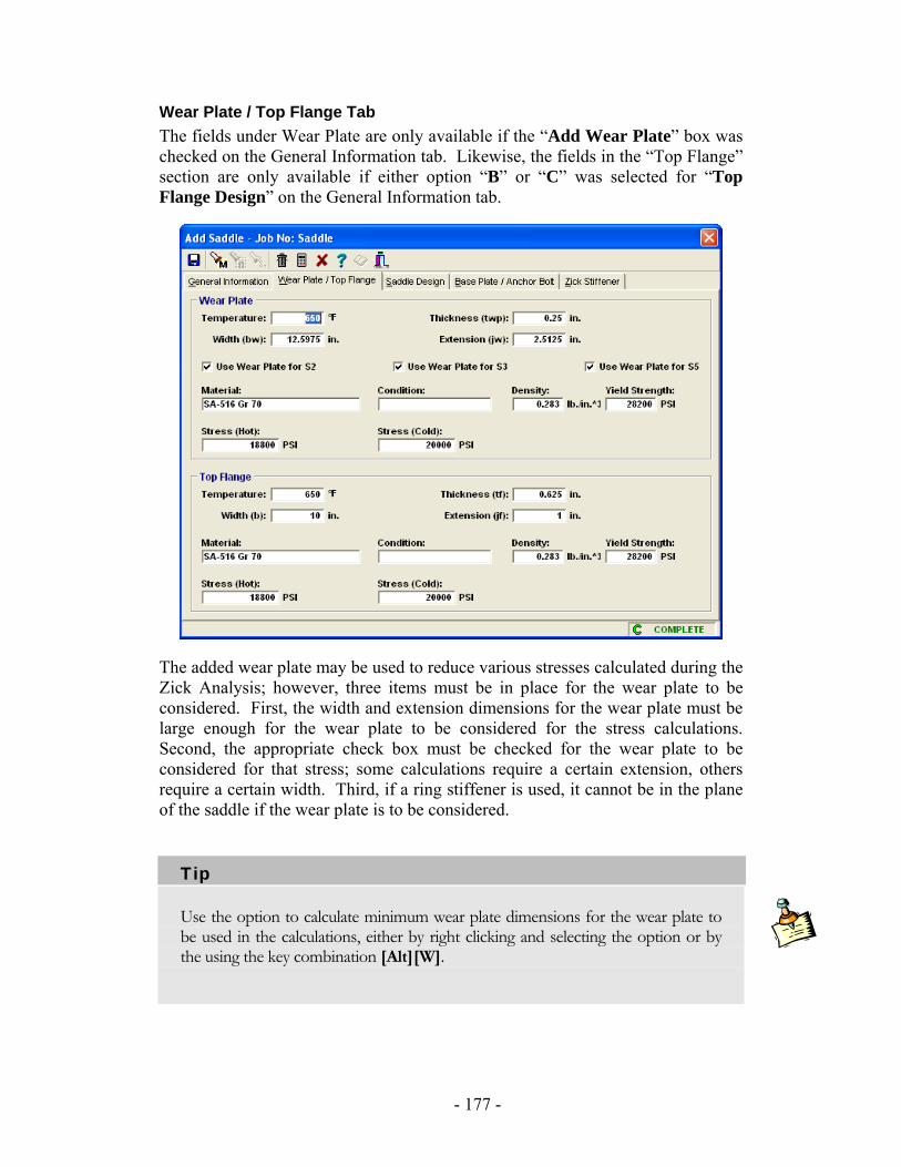
Wear Plate / Top Flange Tab The fields under Wear Plate are only available if the “Add Wear Plate” box was checked on the General Information tab. Likewise, the fields in the “Top Flange” section are only available if either option “B” or “C” was selected for “Top Flange Design” on the General Information tab.
The added wear plate may be used to reduce various stresses calculated during the Zick Analysis; however, three items must be in place for the wear plate to be considered. First, the width and extension dimensions for the wear plate must be large enough for the wear plate to be considered for the stress calculations. Second, the appropriate check box must be checked for the wear plate to be considered for that stress; some calculations require a certain extension, others require a certain width. Third, if a ring stiffener is used, it cannot be in the plane of the saddle if the wear plate is to be considered.
Tip
Use the option to calculate minimum wear plate dimensions for the wear plate to be used in the calculations, either by right clicking and selecting the option or by the using the key combination [Alt][W].
- 177 -
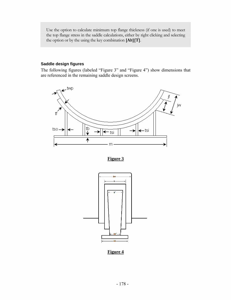
Use the option to calculate minimum top flange thickness (if one is used) to meet the top flange stress in the saddle calculations, either by right clicking and selecting the option or by the using the key combination [Alt][T].
Saddle design figures The following figures (labeled “Figure 3” and “Figure 4”) show dimensions that are referenced in the remaining saddle design screens.
Figure 3
Figure 4
- 178 -
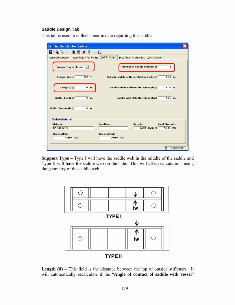
Saddle Design Tab This tab is used to collect specific data regarding the saddle.
Support Type – Type I will have the saddle web in the middle of the saddle and Type II will have the saddle web on the side. This will affect calculations using the geometry of the saddle web.
Length (d) – This field is the distance between the top of outside stiffeners. It will automatically recalculate if the “Angle of contact of saddle with vessel”
- 179 -

field on the General Info tab is changed. If you wish to calculate the angle of contact from this value, then enter the value of “d” here and use the right click menu option or press [ALT][A]. Number of Saddle Stiffeners – The value in this field must be at least two. Two will be the outside stiffeners; any number over two will be inside stiffeners. If the value entered is two, then the field “Inside saddle stiffener thickness (tsi)” is unimportant.
- 180 -
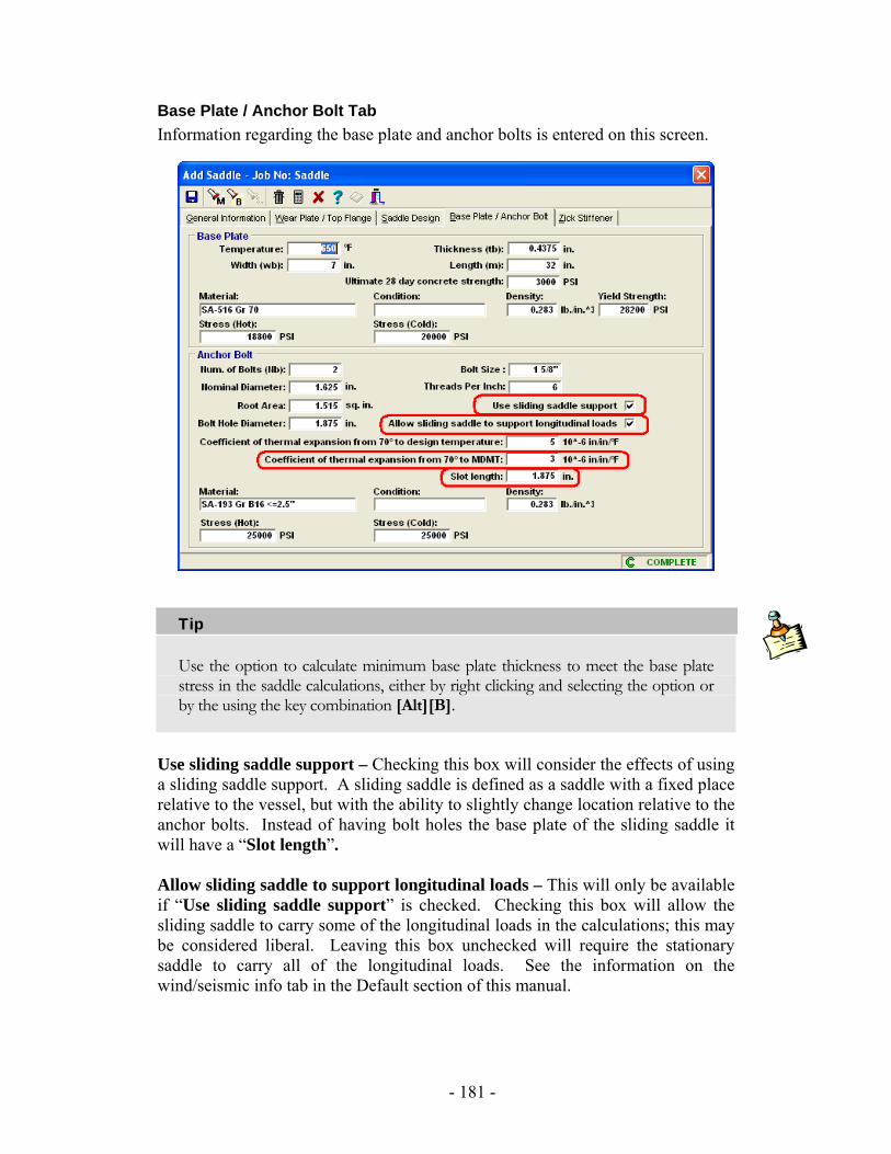
Base Plate / Anchor Bolt Tab Information regarding the base plate and anchor bolts is entered on this screen.
Tip
Use the option to calculate minimum base plate thickness to meet the base plate stress in the saddle calculations, either by right clicking and selecting the option or by the using the key combination [Alt][B].
Use sliding saddle support – Checking this box will consider the effects of using a sliding saddle support. A sliding saddle is defined as a saddle with a fixed place relative to the vessel, but with the ability to slightly change location relative to the anchor bolts. Instead of having bolt holes the base plate of the sliding saddle it will have a “Slot length”. Allow sliding saddle to support longitudinal loads – This will only be available if “Use sliding saddle support” is checked. Checking this box will allow the sliding saddle to carry some of the longitudinal loads in the calculations; this may be considered liberal. Leaving this box unchecked will require the stationary saddle to carry all of the longitudinal loads. See the information on the wind/seismic info tab in the Default section of this manual.
- 181 -

Coefficients of thermal expansion – These will only be available if “Use sliding saddle support” is checked. The two fields here are for the coefficients of thermal expansion of the shell material between ambient temperature (70° F) and design temperature and between ambient temperature (70° F) and MDMT temperature. These values will only be used to check for sufficient slot length for the sliding saddle.
- 182 -
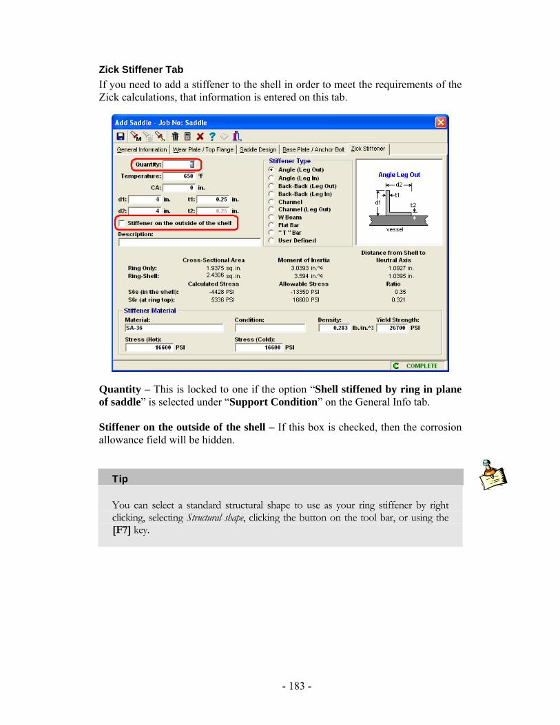
Zick Stiffener Tab If you need to add a stiffener to the shell in order to meet the requirements of the Zick calculations, that information is entered on this tab.
Quantity – This is locked to one if the option “Shell stiffened by ring in plane of saddle” is selected under “Support Condition” on the General Info tab. Stiffener on the outside of the shell – If this box is checked, then the corrosion allowance field will be hidden.
Tip
You can select a standard structural shape to use as your ring stiffener by right clicking, selecting Structural shape, clicking the button on the tool bar, or using the [F7] key.
- 183 -
Note
A ring designed here only looks at the effects of the saddles to see if it is sufficient to bring the vessel into an acceptable stress range. Rings designed in the saddle screens are not intended to meet the requirements of the Zick calculations and the calculations for external pressure on the vessel. Furthermore, no attempt to superimpose these two sets of calculations is made. The user must design rings for the Zick calculations here and design rings for external pressure on the vessel as described elsewhere in this manual.
- 184 -
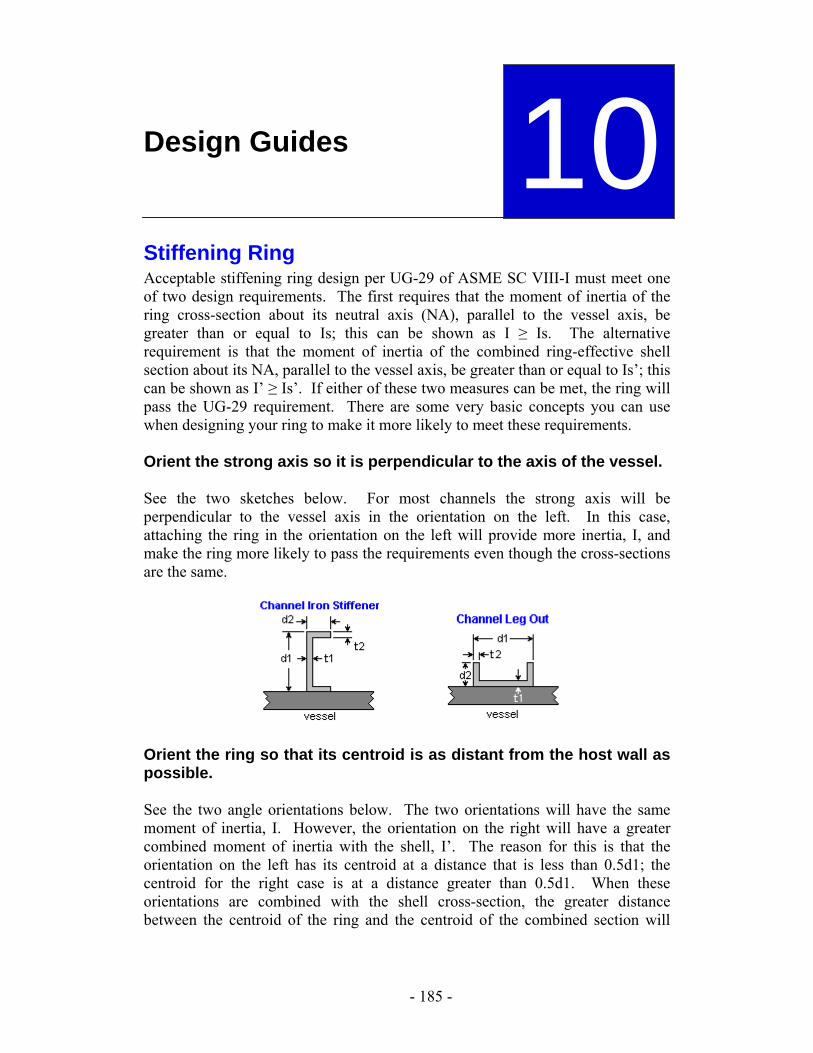
Design Guides
10Stiffening Ring Acceptable stiffening ring design per UG-29 of ASME SC VIII-I must meet one of two design requirements. The first requires that the moment of inertia of the ring cross-section about its neutral axis (NA), parallel to the vessel axis, be greater than or equal to Is; this can be shown as I ≥ Is. The alternative requirement is that the moment of inertia of the combined ring-effective shell section about its NA, parallel to the vessel axis, be greater than or equal to Is’; this can be shown as I’ ≥ Is’. If either of these two measures can be met, the ring will pass the UG-29 requirement. There are some very basic concepts you can use when designing your ring to make it more likely to meet these requirements. Orient the strong axis so it is perpendicular to the axis of the vessel. See the two sketches below. For most channels the strong axis will be perpendicular to the vessel axis in the orientation on the left. In this case, attaching the ring in the orientation on the left will provide more inertia, I, and make the ring more likely to pass the requirements even though the cross-sections are the same.
Orient the ring so that its centroid is as distant from the host wall as possible. See the two angle orientations below. The two orientations will have the same moment of inertia, I. However, the orientation on the right will have a greater combined moment of inertia with the shell, I’. The reason for this is that the orientation on the left has its centroid at a distance that is less than 0.5d1; the centroid for the right case is at a distance greater than 0.5d1. When these orientations are combined with the shell cross-section, the greater distance between the centroid of the ring and the centroid of the combined section will
- 185 -
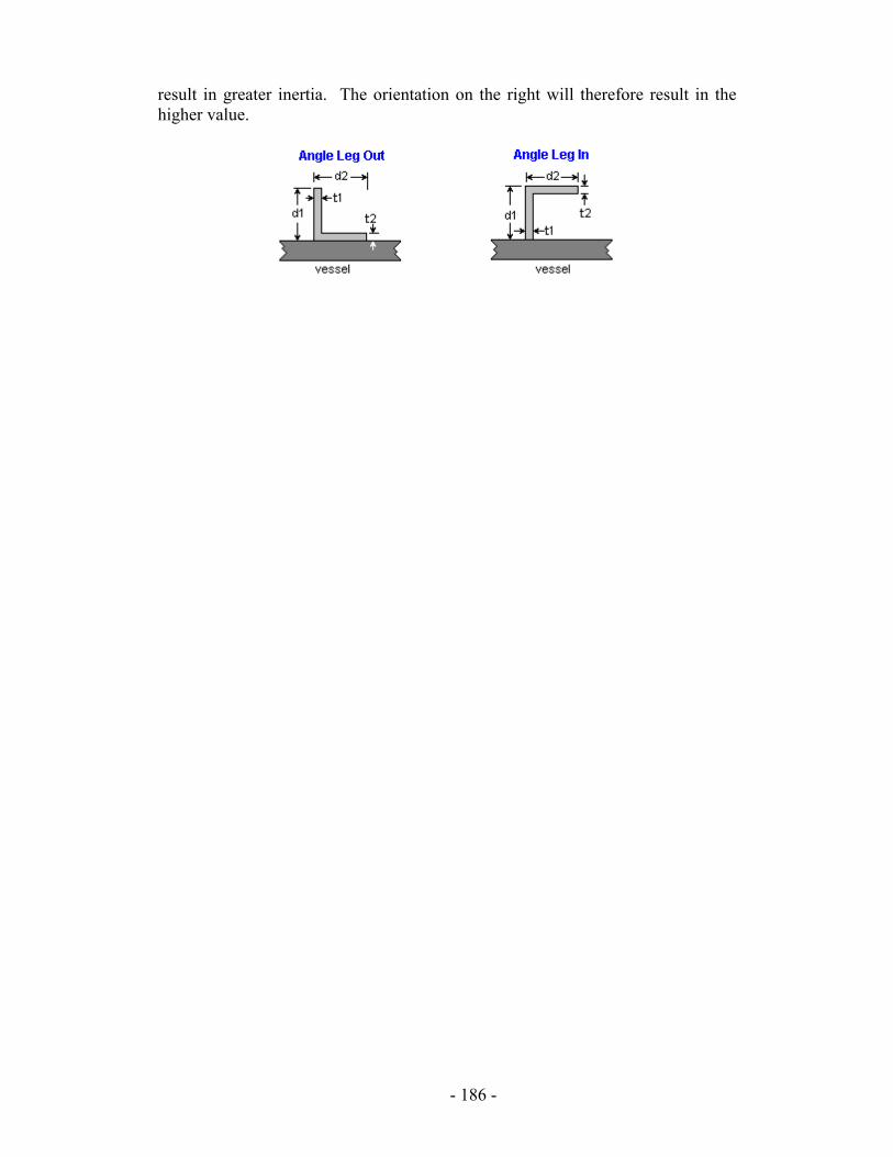
result in greater inertia. The orientation on the right will therefore result in the higher value.
- 186 -
Flange Rigidity Flange rigidity may be a difficult design requirement to satisfy. There may be some options to ignore the requirement, but some of these are temporary and others may not be “good” alternatives. The purpose of this section is to explain the different aspects of flange design that affect the rigidity requirement and thus improve your ability to satisfy the requirement in an economical fashion. If the flange has a hub, it will be more rigid In ASME SC VIII, Div. 1, Appendix 2-14, there are three equations for the rigidity of the flange. The equations for the Integral Type Flange (has an inherent hub) and the Loose Type Flange with Hub are identical except for the V factors in the numerator and the K factors in the denominator. These equations consider the added rigidity due to the hub in determining the rigidity of the flange. The remaining equation determines the rigidity of the flange as a standalone ring. This latter geometry is less rigid by inspection and the equations reflect that. Designs using this third equation are more likely to FAIL the rigidity requirement. If the flange is integral, it will be more rigid The Appendix 2-14 equations for rigidity of the integral type flange and loose type flange with hub differ only by the VI or VL term in the numerator and the KI or KL term in the denominator. The V terms are difficult to summarize by inspection and they require sample cases to point out their trends. The K values, however, are defined in Appendix 2-14, with KI being 0.3 and KL being 0.2. If all other values are constant in the two equations, you can see that the equation for the integral flange will result in a rigidity factor that is 2/3 that of the loose flange. The flange is considered integral or loose depending on how it is attached to the host. Basically, if the attachment is made by full penetration welds it is integral, otherwise it is loose. See Figure 2-4 for more details. Sketch 2-4(7) is an example of how a slip on flange without a hub (or neck) can be attached in order to be considered integral. If the bolting can be reduced, the gasket seating rigidity is more likely to pass The bolt load used in the gasket seating condition for Appendix 2 flanges is determined as the average of the required bolt area and the actual bolt area multiplied by the cold stress of the bolt. The larger that this value gets, the larger the gasket seating moment will become and, in turn, the more severe the requirement for the gasket seating rigidity will be. By inspection you can see that reducing the actual bolt area will reduce the required gasket seating and make the design more likely to pass. You can reduce bolt area by using smaller bolts or by using fewer bolts.
- 187 -
If the bolting strength can be reduced, the gasket seating rigidity is more likely to pass Many grades of bolts have a strength penalty applied as they increase in diameter. For instance, a 2 inch diameter bolt may be given a cold strength of 20,000 psi while a 4 inch diameter bolt is only allowed 17,500 psi. Make sure that you have selected the right diameter (if it applies to your grade). It may be counter intuitive, but using a lower allowable bolt strength may result in a better rigidity index. Using a gasket with lower “m” and “y” values, will reduce the rigidity requirement Gaskets with high “m” and “y” values result in higher required bolt loads and higher gasket reactions. This, in turn, results in a higher moment and more severe requirement for rigidity. If the gasket width can be reduced, the rigidity requirements are more likely to pass If the gasket has a large area to seat— which is a function of the width—the bolt loads and gasket reactions will be higher. Also, the wider the gasket is, the larger the distance between the gasket reaction and the bolt circle becomes. Both of these result in a higher moment and more severe requirement for rigidity. If the gasket diameter can be increased, the rigidity requirements are more likely to pass As the gasket diameter decreases, the distance between the gasket reaction and the bolt circle increases. This results in a higher moment and a more severe requirement for the rigidity. Summary Do the following to make your design more likely to pass rigidity requirements:
• Use a hub. • Attach the flange with full penetration welds to make it integral. • Reduce excess bolting. • Use the correct bolt allowables. • Use gaskets with low “m” and “y” values. • Reduce gasket width. • Increase gasket diameter.
- 188 -
Tubesheet Tubesheets per Part UHX require many more inputs and calculations than most components in ASME Section VIII-I. Because of this, it is very important that all of the dimensions, temperatures, materials, thermal values, etc., are entered correctly. Once this has been done, it is still possible that the design will be failing, incomplete, or passing with an unreasonable thickness. Due to the complex nature of the tubesheet design, this is very likely to occur. In order to finalize the tubesheet design, you can follow the suggestions below to aid in optimizing the tubesheet.
Incomplete tubesheet If the tubesheet is Incomplete, click on the Check Status Icon. This will give you a message telling you why the design is incomplete. If the message indicates that one or more values is unacceptable, then check the tabs to make sure that appropriate values were given for every field. A second possibility is that MDMT calculations are checked on the MDMT tab but that no MDMT loading condition row is present on the conditions tab.
Failed tubesheet If the tubesheet is Failed, click on the Check Status Icon. If the message indicates that the value of “mu*” exceeds 0.6 or that it is less than 0.1, then a more fundamental design change must occur to meet UHX. Review the section in UHX on tubesheet effective properties for triangular or square tube patterns (the pattern you selected) if this is the case. If the message does not indicate this, look at the different failure modes that are present and make sure that a value NAN does not appear in the message. This is a case that may occur in fixed and floating tubesheet configuration “a” designs where certain thermal values are identical. To remedy this, make sure that the thermal values entered are accurate for the operating conditions for each thermal loading case (4-7). Another reason that this may occur is if cumulative corrosion allowances are greater than the plate thickness. This type of failure is typically very easy to resolve by altering the inputs to be valid. If neither the “mu*” or NAN issue is present in the information window, view the different failure modes to decide the best approach to resolve the failing status.
Design failing due to sigma or tau If the design is failing due to sigma or tau, the stresses in the tubesheet are too high. There are several options that may be used to remedy this. If the tubesheet is failing in any loading case (1-7), increasing the tubesheet thickness or increasing the thickness of the integral shell and/or channel (if they exist) are two methods that may be used to decrease sigma; however, only the former method will be effective in reducing tau and both methods may be impractical.
- 189 -
If the tubesheet is failing in the thermal loading cases (4-7), then additional options are available to reduce these stresses. If the requirements of UG-23(e) are met, it may be beneficial to change the SPS,ts value to two times Yield to increase the allowable primary plus secondary stress beyond what three times Stress results in. You also have the option to use the material properties for loading cases 4-7 at operating conditions. If you decide to do this, you can manually enter these values in the conditions grid. Make sure you deselect any components you brought in with the browsers or these values will reset every time you reopen the tubesheet design.
Design failing due to sigmat,o
If the design is failing due to sigmat,o (value is positive), then the design is failing due to the tensile stress in the tubes. This case is the most prohibitive as to the options available to make the design pass. First, make sure that all of the tube information is entered correctly (especially the thermal values for cases 4-7); make sure that the corrosion values are accurate for the tubes if a corrosion allowance was selected for them. Also make sure that the vacuum design pressure for the tube side entered on the tube tab is the vacuum pressure in the channel and not the external pressure on the tubes. If all of these items are correct and the tubes are still failing, then a more aggressive change is needed, such as adding an expansion joint, increasing the tube gauge, or changing the tube material. Before you do this, address the other failure modes to limit the need to make further changes to the tube bundle and to help optimize an expansion joint design if required. If the design is failing due to sigmat,o (value is negative), then the design is failing due to the critical buckling stress in the tubes. First, follow the steps listed for tubes failing to tensile stress. If the design is still failing for any loading case (1-7), look at the length of the unsupported spans and see if they can be reduced by adding tube supports; also, if tube supports are present, try to make sure that the longest unsupported span is between a tubesheet and a tube support and not between two tube supports. If the tubes are failing in the thermal loading cases, you also have the option to use the material properties for loading cases 4-7 at operating conditions. If you decide to do this, you can manually enter these values in the conditions grid. Make sure you deselect any components you brought in with the browsers or these values will reset every time you reopen the tubesheet design. If these items have all been addressed and the tubes are still failing, then a more aggressive approach—as described for tubes failing due to tensile stress—will need to taken.
Design failing due to sigma S or sigma C If the design is failing due to sigma S, then the design is failing due to the stress in the shell integral with the tubesheet. If it is failing in any loading case (1-7), increasing the shell thickness is the most effective way of reducing this stress. However, it may not be acceptable because of geometric constraints with the tube
- 190 -
bundle, the necessity for an unavailable plate size, or cost. If the shell is failing in the primary stress cases (1-3), the option to implement elastic plastic calculations (U-Tube and Fixed only) is available, if this is acceptable in your engineering judgment (see requirements for elastic plastic analysis in UHX). It may be necessary for the shell to satisfy the requirements of UG-23(e) to allow two times Yield for the SPS,s value to qualify for the elastic plastic calculations. If the shell is failing in the thermal cases (4-7), then several options exist. If the requirements of UG-23(e) are met, it may be beneficial to change the SPS,s value to two times Yield to increase the allowable primary plus secondary stress beyond what three times Stress results in. You also have the option to use the material properties for loading cases 4-7 at operating conditions. If you decide to do this, you can manually enter these values in the conditions grid. Make sure you deselect any components you brought in with the browsers or these values will reset every time you reopen the tubesheet design. If the design is failing due to sigma C, then the design is failing due to the stress in the channel integral with the tubesheet. If it is failing in any loading case (1-7), increasing the channel thickness is the most effective way to reduce this stress. However, it may not be acceptable because of geometric constraints with the tube hold pattern on the tubesheet bundle, the necessity for an unavailable plate size, or cost. If the channel is failing in the primary stress cases (1-3), then the option to implement elastic plastic calculations (U-Tube and Fixed only) is available, if this is acceptable to your good engineering judgment (see requirements for elastic plastic analysis in UHX). It may be necessary for the channel to satisfy the requirements of UG-23(e) to allow two times Yield for the SPS,c value to qualify for the elastic plastic calculations. If the channel is failing in the thermal cases (4-7), several options exist. If the requirements of UG-23(e) are met, it may be beneficial to change the SPS,c value to two times Yield to increase the allowable primary plus secondary stress beyond what three times Stress results in. You also have the option to use the material properties for loading cases 4-7 at operating conditions. If you decide to do this, you can manually enter these values in the conditions grid. Make sure you deselect any components you brought in with the browsers or these values will reset every time you reopen the tubesheet design.
Design failing due to tube-to-tubesheet welds The design may fail due to the tube-to-tubesheet welds. There are several ways to makes these pass but most are not practical. Typically, the best way to make the tube-to-tubesheet welds pass is to redesign them. If this is not an option or the weld sizes become unrealistic, the next step is to carefully review the thermal cases for the tubesheet design. You also have the option to use the material properties for loading cases 4-7 at operating conditions. If you decide to do this, you can manually enter these values in the conditions grid. Make sure you deselect any components you brought in with the browsers or these values will reset every time you reopen the tubesheet design.
- 191 -
Wear Plate Vs. Top Flange When deciding whether to add a wear plate or a top flange to a saddle, consider the desired result. To strengthen the vessel wall, add a wear plate; to make the saddle more robust against splitting forces, add a top flange. The same material is added in either case, but to different effect.
Steps for designing a saddle: 1. Design the saddle with no wear plate, top flange, or stiffeners. 2. Review the stress ratios. 3. If vessel stress ratios are high, consider adding a ring or a wear plate. 4. If saddle splitting stress ratios are high, consider thickening the web or
adding a top flange.
- 192 -
Appendix
A Bibliography References - Complete List API 510, Seventh Edition, March 1992, American Petroleum Institute, Washington, D.C.
ANSI / ASCE 7-88, Minimum Design Loads for Buildings and Other Structures, American Society of Civil Engineers, New York, 1990
ANSI / ASCE 7-93, Minimum Design Loads for Buildings and Other Structures, American Society of Civil Engineers, New York, 1994
ANSI / ASCE 7-95, Minimum Design Loads for Buildings and Other Structures, American Society of Civil Engineers, New York, 1996
ANSI / ASCE 7-98, Minimum Design Loads for Buildings and Other Structures, American Society of Civil Engineers, New York, 2000
SEI / ASCE 7-02, Minimum Design Loads for Buildings and Other Structures, American Society of Civil Engineers, New York, 2003
ASME® Boiler and Pressure Vessel Code, Section II, Part D, Current Edition/Addenda, by American Society of Mechanical Engineers, New York, NY.
ASME® Boiler and Pressure Vessel Code, Section VIII, Division I, Current Edition/Addenda, by American Society of Mechanical Engineers, New York, NY.
ASME® Boiler and Pressure Vessel Code Interpretations, Vols. 12-54, by American Society of Mechanical Engineers, New York, NY.
Design of Conical Shells Under External Loads, M.H. Jawad, Article in Journal of Pressure Vessel Technology, May 1980, pp. 231-238.
Design of Process Equipment, 1990, Kanti K. Mahajan, Pressure Vessel Handbook Publishing, Tulsa, OK.
Engineering Mathematics Handbook, Third Edition, 1987, Jan J. Tuma, McGraw-Hill, New York, NY.
Guidebook, For the Design of ASME® Section VIII Pressure Vessels, 1998, James R. Farr & Maan H. Jawad, American Society of Mechanical Engineers, New York.
How to Design Saddle Supports for Horizontal Vessels, Hydro Carbon Processing, 1972, Gene B. Moody, pp. 157-160.
International Building Code, 2000 Edition, International Code Council, 2000
International Building Code, 2003 Edition, International Code Council, 2003
- 193 -
Local Stresses in Spherical and Cylindrical Shells Due to External Loading, K.K. Wichman, A.G. Hopper, and J.L. Marshen, WRC Bulletin No. 107, December 1968, Revised March 1979.
Machinery’s Handbook, 1988, Erik Oberg, Franklin D. Jones, and Holbrook L. Horton., Industrial Press, Inc., New York, NY.
Manual of Steel Construction, 1980, American Institute of Steel Construction, Inc., Chicago, IL.
Mark’s Standard Handbook for Mechanical Engineers, 1986, Eugene A. Avallone and Theodore Baumeister III, McGraw-Hill, Inc., New York, NY.
Mechanical Design of Heat Exchangers and Pressure Vessel Components, 1984, K.P. Singh and A.I.Soler, Arcturus Publishing, Cherry Hill, NJ.
Mechanical Design of Process Systems, Vol. I, 1986, Keith A. Escoe, Gulf Publishing Co., Houston, TX.
Pressure Vessel Cookbook, 1982, Graham McAllister, CTM Publishing, Lakewood CA.
Pressure Vessel Design Handbook, 2nd Edition, 1986, Henry H. Bednar, Van Nostrand Reinhold Co., New York, NY.
Pressure Vessel Design Manual, 2nd Edition, 1997, Dennis R. Moss, Gulf Publishing Co., Houston, TX.
Pressure Vessel Handbook, 10th Edition, 1995, Eugene F. Megyesy, Pressure Vessel Publishing, Inc., Tulsa, OK.
Pressure Vessels, The ASME® Code Simplified, 1993, Robert Chuse and Bryce E. Carson, Sr., McGraw-Hill, Inc., New York, NY.
Process Equipment Design, 1959, Lloyd E. Brownell and Edwin H. Young, Wiley & Sons, New York, NY.
Roark’s Formulas for Stress & Strain, Sixth Edition, 1989, Warren C. Young, McGraw-Hill, Inc., New York.
Stress Concentration Design Factors, 1953, Peterson, R. E., John Wiley & Sons, Inc., New York.
Stresses in Large Horizontal Cylindrical Vessels on Two Saddle Supports, The Welding Journal Research Supplement, September 1953, L. P. Zick.
Structural Analysis and Design of Process Equipment, Second Edition, 1989, Maan H. Jawad and James R. Farr, John Wiley & Sons, New York, NY.
Structural Engineering Handbook, Fourth Edition, 1998, Edwin H. Gaylord, Jr., Charles N. Gaylord, James E. Stallmeyer, McGraw Hill, New York, NY
Theory and Design of Pressure Vessels, Second Edition, 1991, John F. Harley, Van Nostrand Reinhold Co., New York, NY.
Uniform Building Code, 1991 Edition, 1991,International Conference for Building Officials, Whittier, CA.
Uniform Building Code, 1994 Edition, 1994,International Conference for Building Officials, Whittier, CA.
Uniform Building Code, 1997 Edition, 1997,International Conference for Building Officials, Whittier, CA.
- 194 -
Frequently Asked Questions The following questions and answers have been compiled to assist the user with operation of Advanced Pressure Vessel.
General Questions Q. How can I find out if there are any updates or modifications to the
program? A. CEI maintains a website that has all of the latest information and maintenance
releases for our programs. The address is www.computereng.com.
Q. I need to calculate the stresses on a horizontal vessel. How can I do that with Advanced Pressure Vessel?
A. Computer Engineering sells add-in modules for use with Advanced Pressure Vessel. These modules are: “Zick, Saddles, & Seismic,” “Advanced Tower Design,” and “Legs, Lugs, & Seismic.” You can purchase any or all of these modules to add additional functionality to Advanced Pressure Vessel. In your case, Zick, Saddles, & Seismic would be the add-in module you need. It not only calculates the stresses due to bending, but it also calculates wind and seismic stresses plus allows you to design custom saddles. See Chapter 1 for additional product information.
Q. Why do you sell add-in modules instead of having them built into Advanced Pressure Vessel?
A. With various add-in modules, the user can pick and choose which features they need. This saves you unnecessary cost since you only purchase what you need. If you need all three add-in modules, contact sales for special pricing.
Q. How can I send a vessel design to a customer or colleague who also has Advanced Pressure Vessel without sending copies of the reports or all my designs?
A. Create a temporary directory, select “Utilities | Transfer,” select the job you wish to send to your customer and transfer it to the temporary directory. For more information, see “Transfer” in Chapter 7.
Q. What is the “BDE”? A. The Borland Database Engine, commonly referred to as “BDE,” provides a
way for the program to communicate with database files. Most programs that use Paradox database files will use the BDE for database communications.
Q. I received an error message when starting the program that includes the phrase “EDBEngine” somewhere in the error text. What do I need to do to correct this?
A. Install the BDE files directly off of the CD. They’re in the “BDE_INSTALL” and “BDE_Upgrade” folders on the CD.
- 195 -
Q. What causes the message “Network Error”? A. This error is returned by your network and is not a program error. Please
contact your network administrator or MIS department for assistance.
Q. The program seems to run extremely slow, taking minutes just to open or save a component design.
A. Many things can cause this, but a very common cause is over-aggressive anti-virus software. Many popular brands, such as McAfee, have the ability to exclude certain files or directories from scanning. Try excluding the CEI folder on your hard drive from constant scanning. (Don’t forget to exclude the remote data and support folders on your server if you are running a networked version.) This can often result in a 25-50% speed increase, even more on networked systems. You can also go to Utilities | Show 3D graphics to turn off the 3D images for increased speed.
Q. Is there any thing else I can do to make Advanced Pressure Vessel run faster?
A. There are several things you can do to help the program run faster. The best is to add more memory and the more the better. With memory prices low, this is a good solution. Another solution is to replace your hard drive with a drive that has faster access and transfer rates. A third solution is to upgrade your processor. All of your Windows programs will benefit from these changes!
Vessel Questions Q. I have a shell that is made from pipe. How do I get the program to take
the pipe reduction required by the ASME® Code? A. Using the pop-up pipe table while designing the shell, head, or nozzle, tells
the program that the vessel component is made from pipe.
Q. How do I convert my design from English to metric? A. To convert the units of measure you must copy your vessel design to a new
design. This is done by selecting “File| Copy/ Convert Units” from the main menu. After selecting a vessel design to copy, enter a “job number” and “vessel number.” Before the copy process continues, select “Convert to metric” (if the design is English units of measure) or “Convert to English” (if the design is metric units of measure) to convert the units of measure.
Q. How to I copy a design to a new job number? A. To copy the job to a new number, you must use the Copy Convert feature.
This is done by selecting “File| Copy/ Convert” from the main menu. After selecting a vessel design to copy, enter a “job number” and a “vessel number.” Both items must be changed so that the copied job can be uniquely identified. Leave the convert to box unchecked.
- 196 -
Q. When calculating external pressure for a shell, what does the program do when “Calculate Dimension L” is selected from the pop-up menu?
A. For the given material, external pressure, external temperature, diameter, and thickness of your shell design, the program will calculate the maximum allowable distance between any two adjacent lines of support for the shell using the rules from UG-28. If the actual maximum distance between any two adjacent lines of support is less than or equal to this calculated value, then stiffening rings will not be required for the shell design. If the actual maximum distance between any two adjacent lines of support is greater than this calculated value, then either the shell will need to be made thicker or stiffening rings will be required for the shell design. In any case, enter the actual maximum distance between any two adjacent lines of support into the dimension L field on the shell input form since it will impact your nozzle design.
Q. When checking the calculations for a cone-cylinder juncture, how do I calculate the value for the axial load due to weight?
A. To calculate the axial load, divide the weight of the vessel acting at the cone-cylinder juncture by the mean shell circumference at the juncture (f = W / Pi Dm, where Dm is the mean diameter of the shell).
Q. I need to design a bolted flat head that corresponds to either sketch (j) or sketch (k) of Fig. UG-34. When I try to design a flat head, however, configurations (j) and (k) are not available for selection. What do I do?
A. Flat head designs that correspond to sketches (j) and (k) of Fig. UG-34 are commonly referred to as blind flanges. They require special flange calculations per Appendix 2 in order to design them. To design a blind flange using the program, select “Flange | Appendix 2” from the design menu and, when the input screen appears, select “Blind” as the flange type.
Q. When designing an Appendix II flange, why don’t my thicknesses match ANSI published values?
A. Appendix 2 of Section VIII, Division I, is not intended for designing ANSI flanges. Also, ANSI flanges do not require calculations per UG-44.
Q. How do I enter an Elliptical Pipe Cap? A. This is entered as you would a standard head. To do this, you must highlight
the host component, then select “Component” | “New” | “Head.” This will bring up a “New Head” window. Select “Ellipsoidal” for the head type and click on the “P” flashlight to open the “Pipe Database.” Select the same pipe size as the host.
Q. How do you change the pressure, temperature, or corrosion allowances for an entire design?
A. You can open the “Edit Vessel” Screen and make the changes to the “Design Info” tab. To do this, double click on the vessel number in the vessel browser (upper left pane of the main screen). This will bring up an “Edit Vessel” Window. Select the “Design Info” tab. Here, set the values that you wish to change.
- 197 -
If you change the Internal/External Temperature or Pressure or any of Corrosion Allowances, a Global Update window will appear when you save and exit the input form. This will allow you to set the updated values for all the components of the design. If any component has a value other than what was listed in the Edit Vessel window, it will be “Flagged” and you will be questioned as to whether or not you want to update it to a new value. Once this is complete, any component that fails as a result of the new settings will show a red X next to it in the lower left pane.
Q. Can more than one key be plugged into a computer at a time or more than one program be stored on a single key?
A. Only one CEI key can be plugged into a computer at a time, but more than one program can indeed utilize a single key. Please contact CEI Tech Support regarding this process.
If you have any additional questions, please contact our technical support department through one of the following methods: e-mail: [email protected] FAX: 1 (877) 228-0680 (toll free inside the US) VOICE: 1 (816) 228-2976 Technical Support hours are posted online at Computer Engineering’s Website.
www.computereng.com/support Technical support is also available through our web site via the below link.
Direct Support Request Link
- 198 -