Advanced Machining Processes Professor Vijay K. Jain...
29
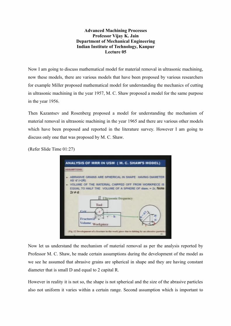
Advanced Machining Processes Professor Vijay K. Jain Department of Mechanical Engineering Indian Institute of Technology, Kanpur Lecture 05 Now I am going to discuss mathematical model for material removal in ultrasonic machining, now these models, there are various models that have been proposed by various researchers for example Miller proposed mathematical model for understanding the mechanics of cutting in ultrasonic machining in the year 1957, M. C. Shaw proposed a model for the same purpose in the year 1956. Then Kazantsev and Rosenberg proposed a model for understanding the mechanism of material removal in ultrasonic machining in the year 1965 and there are various other models which have been proposed and reported in the literature survey. However I am going to discuss only one that was proposed by M. C. Shaw. (Refer Slide Time 01:27) Now let us understand the mechanism of material removal as per the analysis reported by Professor M. C. Shaw, he made certain assumptions during the development of the model as we see he assumed that abrasive grains are spherical in shape and they are having constant diameter that is small D and equal to 2 capital R. However in reality it is not so, the shape is not spherical and the size of the abrasive particles also not uniform it varies within a certain range. Second assumption which is important to
Transcript of Advanced Machining Processes Professor Vijay K. Jain...
Advanced Machining ProcessesProfessor Vijay K. Jain
Department of Mechanical EngineeringIndian Institute of Technology, Kanpur
Lecture 05
Now I am going to discuss mathematical model for material removal in ultrasonic machining,
now these models, there are various models that have been proposed by various researchers
for example Miller proposed mathematical model for understanding the mechanics of cutting
in ultrasonic machining in the year 1957, M. C. Shaw proposed a model for the same purpose
in the year 1956.
Then Kazantsev and Rosenberg proposed a model for understanding the mechanism of
material removal in ultrasonic machining in the year 1965 and there are various other models
which have been proposed and reported in the literature survey. However I am going to
discuss only one that was proposed by M. C. Shaw.
(Refer Slide Time 01:27)
Now let us understand the mechanism of material removal as per the analysis reported by
Professor M. C. Shaw, he made certain assumptions during the development of the model as
we see he assumed that abrasive grains are spherical in shape and they are having constant
diameter that is small D and equal to 2 capital R.
However in reality it is not so, the shape is not spherical and the size of the abrasive particles
also not uniform it varies within a certain range. Second assumption which is important to

note is volume of the material chipped off from work piece is equal to half the volume of a
sphere of diameter equal to 2 small R, here please note that this 2 small R is not equal to the
diameter of the sphere. 2 R is something different as we can see.
So let us see the second assumption again volume of the material chipped off from the work
piece is equal to half the volume of a sphere of diameter equal to 2 R, note that here 2 R is
not equal to D because D is the diameter of the abrasive particle or the grit while 2 R is the
assumed diameter of the fractured volume considered as sphere.
(Refer Slide Time: 03:10)
As you can see here that this is the grit and when it is penetrating upto this depth it is
assumed that the volume of this is equal to the semi sphere having the radius equal to 2 R, as
you can see here, here is the tool which is vibrating ultrasonically and here is the grit having
diameter D and this is the, 2 R is the diameter of the hemisphere of the fractured volume
That figure indicates clearly that capital R is equal to D by 2 where small D is the diameter of
the abrasive grit and at the bottom you can see small R is the radius of the hemisphere of the
fractured volume of the material and then other things, H is the penetration to which the
abrasive particle is penetrating inside the work piece surface and capital R minus H is the rest
of the arm of this figure shown over here, it will be utilized for the calculation in the
following slide.

(Refer Slide Time: 04:32)
So, material removal by throwing mechanism and hammering mechanism, two of the
mechanism that have been considered, I will show you what do they mean in fact in the
following slide as we can easily understand here, suppose this is the tool and here is the work
piece and say this is the abrasive particle in the slurry when this tool is vibrating
ultrasonically, this will hit this abrasive particle as a result of this, this particle will move
towards the work piece and penetrate inside the work piece as in this particular case or in this
particular case.
So this is known as throwing model because here particle is thrown by the tool towards the
work piece. In the second case, this is the work piece, this is the tool and if the gap between
the bottom face of the tool and top face of the work piece is smaller than the size of the

abrasive particle then this tool will be hitting the abrasive particle and part of the abrasive
particle will penetrate inside the tool part of it will penetrate inside the work piece and this is
known as hammering model.
Other modes of material removal like cavitation and chemical action of the slurry on the
work piece are neglected in this particular model. Radius of the crater formed due to fracture
are as I have shown in the figure in the earlier slide, here crater is assumed to be hemi-
spherical as shown over here with the dash dash line. Radius R in terms of abrasive particle
radius and depth of penetration is small H as I have shown earlier they can be expressed like
R square is equal to capital R square minus within bracket R minus H whole square and this
is very clear from the previous slide where the figure is shown.
So R square and R square will cancel we are left with 2 R H minus small H square and this
comes out to be approximately equal to 2 R H, here H is the depth of penetration and as you
can see here this and this is very small and square of this depth of penetration H square will
become still smaller hence it can be neglected now let us find out what is the volume of
material removed per grit per cycle and let it be expressed by VG.
Now this VG will be equal to half of the volume of the sphere, now here you can see we have
assumed that this is the semi sphere so actually this is the sphere so half of the volume of the
sphere the volume of the sphere is given by 4 by 3 pi R cube and half of it becomes half
multiplied by 4 by 3 pi R cube and this comes out equal to 2 by 3 pi within bracket 2 R H
raise to power 3 by 2 and here as you can see in the previous line we have shown that R is
equal to approximately 2 R H so if we take this one then we get this equal to K1 H into D
whole raise to power 3 by 2 millimeter cube per grit per cycle, this is the volume where K1 is
the constant which can be evaluated by the experimental results. H and D are to be given in
millimeter. Here H is the depth of penetration as have been shown over there.

(Refer Slide Time: 08:55)
Now let N be the number of impacts per cycle where N is an inverse function of cross-
sectional area of the grit and whose diameter is D. Now let us see here two figures on the left
side there is a abrasive particle of the smaller size having diameter D and on the right side
you has the abrasive particles of the larger size.
Now as you can see larger the size of the (())(09:31-09:39 inaudible) particle larger number
of the abrasive particles are covering the same area. So you can write N is equal to K2 by or
K2 upon D square where K2 is a constant of proportionality.

(Refer Slide Time: 09:55)
Now is every grit active? This is the question which arises as you can see here in the figure,
suppose this is the tool and there are various abrasive particles whichever particle is hit by the
tool the question is whether every particle is reaching to the work piece and hitting the work
piece or some of them are just dying out their energy.
Energy die out while travelling from the tool towards the work piece so what it is done let K
be the probability that a particular grit under the tool is active or it is hitting the work piece
and removing the material then the volume VC is the material removed per cycle can be
given by K multiplied by VG into number of impacts which becomes equal to K multiplied
by K1 into K2, H D raise to power 3 by 2 divided by D square that comes out to be equal to
K into K1 into K2 under the root H cube by D.
Now here we have substituted the value of VG that was found in the previous slide so
volumetric material removal rate MRRV is equal to K, K1, K2 multiplied by F under the root
H cube by D, and this unit is cubic millimeter per second. Now here we can see it is
multiplied by F, where F is the frequency of vibration of the tool and here you can see, you
can determine K, K1, K2 from the experimental results. F is already known that is frequency
of vibration and D is the diameter of the grit which is also known but we do not know the
depth of penetration H that is given over here.
So we will be using two different models, the question arises how to know the depth of
penetration there are the two models proposed by the Professor M. C. Shaw one is the
throwing model, another is the hammering model which I have already explained to you, this

is the throwing model and this is the hammering model or this is the throwing model and the
hammering model.
(Refer Slide Time: 12:36)
As you can see clearly, grit is thrown by the tool and it is penetrating inside the work piece F
TH is the force acting when the tool is hitting the abrasive grit in the throwing model.
(Refer Slide Time: 12:57)
A grain is thrown on to the work piece by the tool as we have already seen in the slide and
this is very clear from the slide on the figure on the right side and we can see T is the time
that is equal to 0 that means when time is zero the tool is just touching the abrasive particle.
Now the motion of vibration can be expressed or the displacement can be expressed as Y is

equal to A by 2 sin 2 pi FT, where we already know that A by 2 is the amplitude of vibration,
F is the frequency of vibration and T is the time at which we are trying to find out the
displacement.
Now velocity of tool can be evaluated by DY over DT, that is equal to Y dot and if you
differentiate the earlier equation it comes out to be pi AF cos 2 pi FT. The maximum velocity
that a tool can achieve is given by Y dot maximum equal to pi AF and this will be maximum
only when value of the cos 2 pi FT is equal to 1 so for cos 2 pi FT is equal to 1 we achieve Y
dot maximum is equal to pi AF.
Now here there is very important assumption in determining the maximum velocity of the grit
particle or the tool specially when we are assuming that the grit also leaves the tool at this
particular maximum velocity at which the tool is vibrating. This tells the tool vibration where
amplitude of vibration and the time both are shown.
Now from this we can find out the kinetic energy content by the abrasive particle, we already
know kinetic energy is given by half MV square while M is the mass of the abrasive particle,
V is the velocity of the abrasive particle with which it is moving towards the work piece or it
is hitting the work piece and as you can see here, the mass is given by pi by 6 D cube rho A
where rho A is the density of the abrasive particle and small D is the diameter of the abrasive
particle and pi square A square F square is the V square or the maximum velocity of the
abrasive particle with which it is hitting the work piece.

(Refer Slide Time: 15:53)
Now full kinetic energy is absorbed by the work piece before the particle comes to rest, it is
assumed it will result in penetration equal to H THW, suffix THW or subscript THW
indicates TH stands for throwing model and W stands for work piece into the work piece,
then the average work done is given by half FH THW where H we can determine from the
figure as you can see here it is assumed that the variation in the force is triangular in nature.
Assuming that the force vibration during force variation during penetration is triangular in
nature. Average contact stress sigma W on the work surface is equal to brittle fracture
hardness of the work piece material with this assumption sigma W is given by F divided by pi
H THW D now here pi DH THW, just a minute, H THW.

(Refer Slide Time: 17:28)
Now this portion pi D is the periphery of the spherical hemi-spherical penetration that we are
assuming and this gives the H THW so from this we can find out whatever the area over
which force F is acting from there we can determine the sigma W. So we get F is equal to pi
H this will be pi H THW DH substituting sigma W is equal to H, it is known that kinetic
energy of a particle is equal to the work done.
So we can equate the work done to the kinetic energy of the abrasive particle, so we can see
here half MV square is equal to half pi upon 6 D cube rho A multiplied by pi square A square
F square is equal to pi H small H DH THW. Now if we simplify this equation we get the
value of the H THW is equal to pi AFD multiplied by under root rho A divided by 6 capital H
now from here one can determine the depth of penetration in the throwing model in the work
piece and this value can be substituted in the equation which we initially (())(19:15 19:24
inaudible).

(Refer Slide Time: 19:27)
This value of H THW from equation 3 can be substituted in the equation 1 derived for
evaluation of MRR VTH where VTH is volumetric material removal rate in throwing model
by the throwing model. In the same way H can be derived if the material removal takes place
due to hammering action as follows, this clearly indicates how the hammering model is going
to work and what is happening in the hammering as you can see here also part of the abrasive
is penetrated inside the tool and part of it is penetrated inside the work piece.
(Refer Slide Time: 20:13)
Now here it indicates the tool the topmost position of the tool where from it starts vibration,
mean position of the tool and bottom most position of the tool and at the bottom most
position of the tool it is hitting the abrasive particles or hammering the abrasive particle. Now

it is assumed that the grain is hammered into work piece as shown in the above figure, it
simply means that the gap between the bottom face of the tool and top face of the work piece
is smaller than the size of the grain that we can see here.
(Refer Slide Time: 20:55)
This is the size of the grain and this is the bottom face of the tool and this is the top face of
the work piece. So tool will hit the abrasive particle only when this gap becomes smaller than
the size of the abrasive particle or the grit size. Mean speed of the tool is quite low, mean
static feed force is applied to the tool and it is expressed as F and this is equal to mean force
of tool on the grit.

(Refer Slide Time: 21:39)
Delta T is the duration of impact, FI maximum is the maximum value of impact force FI
which is acting on the abrasive particle, force will vary with the depth of penetration by the
grit, exposed contact area between the crane and the work piece are different and grain and
tool is also different, this indicates, the delta T indicates the period during which abrasive is
contact with the tool and work piece both and capital D indicates the cycle time.
This average force in this particular situation can be evaluated with the help of this equation,
F average is equal to 1 upon T integration 0 to T FI T DT, where T is the cycle time.

(Refer Slide Time: 22:40)
Now there are various positions of the tool during a cycle you can see here top position of the
tool which is indicated by C, mean position of the tool is indicated by O, when tool touches
the grit is indicated by A and bottom position of the tool is indicated by B and work piece is
shown over there tool are separately shown there the cycle time is capital T and the time
required for moving from O to B is T by 4 and the time during which abrasive and tool and
work piece are in contact with which each other is delta T.
The movement from A to B is due to impact on the abrasive particle as the tool touches the
abrasive it experiences the resistance to move. Let us assume nature of variation of force FI
as triangular, so you can see here FI maximum is the maximum force which is experienced by
the abrasive particle. FI is the force and delta T as I have mentioned earlier is that period
during which abrasive tool and work piece are in contact.

(Refer Slide Time: 24:07)
Due to this force, the abrasive will partly penetrate in the tool and the depth of penetration is
H suffix TH and partly in the work piece and it is expressed as H suffix WH where W stands
for work piece, H for hammering model. Total indentation H H during hammering is given by
the sum of the penetration in the tool and the work piece and it can be expressed as H H is
equal to H TH plus H WH, this is very clear from this figure H TH is the penetration depth
inside the tool and H WH is the penetration depth inside the work piece and force F is acting
on the grit particle.
(Refer Slide Time: 25:02)
Average velocity during the quarter cycle OB is given by A by 2 divided by T by 4, T by 4 is
the time taken in the quarter cycle and A by 2 is the amplitude and this is given by 2A by T. If

delta T be the time required to travel from A to B that is approximately total penetration depth
H H then delta T is equal to H H that is the total depth of penetration divided by the velocity
that is given by 2A by T.
So we can simplify this H H is equal to H TH plus H WH multiplied by T divided by 2A,
now here let F average be the average force acting during one cycle then F average can be
written as 1 by 2 F I maximum multiplied by H TH plus H WH multiplied by T by 2 into A
and divided by 1 by T.
(Refer Slide Time: 26:21)
Here you can see since there is a triangular force variation that we have assumed so the
average will be the, this is the F maximum and here is the 0. So average will be F maximum
divided by 2 that you can see the first term and H TH plus H WH multiplied by T divided by
A2 that gives you the time delta T during which this force is acting and capital T is the cycle
time so this will give you the average force.
Or you can write it like this FI maximum is equal to 4 F average multiplied by A divided by
H TH plus H WH, now maximum force per grit will be obtained when the total force that is
acting on the tool is divided by total number of particles which are being hit by the tool so let
this be the capital N as the total number of abrasive particles which are being hit by the tool.

(Refer Slide Time: 27:42)
Now what is going to be the maximum stress developed in the work piece because abrasive
particle is in contact with the tool as well as the work piece and depth of penetration in the
tool as well as work piece are different so the area on which the force is acting will also be
different.
So the stress is developed in the tool as well as the work piece will be different, let us find out
the maximum stress developed in the work piece it is given by sigma suffix W is equal to FI
maximum divided by N multiplied by 1 over pi D H WH, the term within the bracket gives
you the area.
Same way you can find out the maximum stress developed in the tool that is sigma T is equal
to FI maximum divided by N within bracket 1 upon pi D H TH, now substitute the value of
FI maximum in above equation A then you get the stress sigma W in the work piece that is 4
F average A divided by H TH plus H WH multiplied by 1 over N pi D H WH.
Assumption here made is as follows, number of grits acting is inversely proportional to the
square of the diameter for a given area of tool face, I have already shown one slide regarding
this and we have already seen then N becomes proportional to 1 by D square and K 2 this
becomes equal to K 2 divided by D square where K 2 is the constant of proportionality.

(Refer Slide Time: 29:38)
Or you can write down sigma W is equal to 4 F average A D divided by H T plus H W into
K2 whole of it multiplied by 1 over pi H W, now you can further simplify it and you get it as
H W square is equal to 4 F average A D divided by sigma W pi K 2 within bracket lambda
plus 1.
Where lambda is equal to H T over H W and depth of penetration will be inversely
proportional to the strength of the work piece or the tool, if higher the strength lower will be
the depth of penetration that is why you can see here H T over H W is equal to sigma W over
sigma T. Stress sigma W can be replaced by brinnel hardness number H, both are the same,
sigma W is equal to H W that is the work piece brinnel hardness number.

(Refer Slide Time: 30:51)
Above equation can now be simplified as H W square is equal to 4 F A D square divided by
pi K2 C D HW within bracket lambda plus 1. Substitute the value from HW in the equation
(())(31:09-31:17 inaudible) equal rate by hammering model comes out to be equal to K, K1,
K2 multiplied by the term given over here 4 F A divided by K2 C D HW within bracket
lambda plus 1 bracket closed whole raise to power 3 by 4 into D raise to power 1 by 4
multiplied by F. I have already mentioned F is the frequency of vibration.
Now from the theoretical, okay let me go back once again, here one point you have to note
that the volumetric material removal rate is proportional to D raise to power 1 by 4 but
practically it is observed something different rather than D raise to power 1 by 4, I will
explain it later on.

(Refer Slide Time: 32:07)
From the theoretical calculations it has been found that material removal rate in throwing
model from throwing mechanism is much much smaller than MRR VHM that is the
volumetric material removal rate from hammering model and it is many times so small
compared to hammering model that it can be neglected.
The discrepancy is observed between experimental and theoretical result, theoretical results
calculated by Shaw’s model, lot of discrepancy has observed with the experimental results
then later on Professor Shaw tried to explain them, the discrepancy as follows.

(Refer Slide Time: 32:55)
What he considers that actual shape of the grain is not spherical and they are not smooth also
now I had mentioned this particular point earlier also and they have projections of average
diameter and he assumed that it is equal to D1 and D1 is proportional to D square or D1
square is proportional to D raise to power 4.
But MRR V is proportional to D raise to power 1 by 4, so if we substitute there the value of
this in the hammering model then we get D raise to power 4 whole raise to power 1 by 4 you
get proportional to D and experimentally it is observed that volumetric material removal rate
is proportional to D.
As F increases MRR V also increases, in practice we want a certain value of F it starts
decreasing because of abrasive grit gets crushed under heavy load as F increases MRR V also
increases, in practice we want a certain value of F that is the force it starts decreasing because
abrasive grit gets crushed under heavy load.

(Refer Slide Time: 34:17)
Now let us take one example to understand how the forces etc. can be calculated, find out the
approximate time required to machine a hole of diameter equal to 6 millimeter in a tungsten
carbide plate whose fracture hardness is equal to 6900 mega pascal and it is of thickness
equal to 1 and half times of hole diameter the mean abrasive grain size is 0.015 millimeter,
the feed force is equal to 3.5 newton the amplitude of tool oscillation is 25 micron and the
frequency is equal to 25 kilo hertz, the tool material used is copper having fracture hardness
equal to 1.5 into 1000 newton per millimeter square. The slurry contains one part abrasive to
one part of water, take the values of different constants as K1 is equal to 0.3, K2 is equal to
1.8 millimeter square, K3 is equal to 0.6 and abrasive density equal to 2.8 gram per cubic
centimeter, also calculate the ratio of the volume removed by throwing mechanism to the
volume removed by hammering mechanism.

(Refer Slide Time: 35:46)
This problem has been taken from the book Advanced Machining Processes published by
Allied Publishers, this problem, to solve this particular problem or before solving this
particular problem let us see what are the available data, hole diameter is equal to 6 into 10
raise to power minus 3 meter all the data that are given have been converted in meter so that
is why you can see here plate thickness is equal to 1.5 into hole diameter that comes out to be
9 into 10 raise to power minus 3 meter.
Mean abrasive grain size it should be grit not the grain, mean abrasive grit size is equal to 1.5
into 10 raise to power minus 5 meter, feed force is equal to 3.5 newton, amplitude of tool
oscillation is given by 25 into 10 raise to power minus 6 meter and frequency of oscillation is
25000 cycles per second, fracture hardness of work piece material that is sigma W is equal to
HW is equal to 6.9 into 10 raise to power 9 newton per meter square.
Fracture hardness of tool material that is H T is equal to 1.5 into 10 raise to power 9 not 109
this is 10 raise to power 9 newton per meter square and abrasive grain density rho A is equal
to 3.8 into 10 raise to power 3 KG per meter cube. So the value of the lambda can be written
as lambda is equal to HW divided by HT that is equal to 4.6, K1 is equal to 0.3, K2 is equal
to 1.8 millimeter square and that come out to be 1.8 into 10 raise to power minus 6 meter
square and K3 is equal to 0.6 and C is equal to 1. Here C is nothing but the concentration.

(Refer Slide Time: 37:49)
The following procedure should be adopted to solve the problem, first we should try to find
out what is time required to machine the hole, we know that the volume of material removed
using ultrasonic machining can be calculated using the following relationship that is V is
equal to K1 K2 K3 under the root H raise to power 3 divided by D into F.
(Refer Slide Time: 38:17)
First step to be followed in the solution of this problem is calculate the value of H which is
different for throwing model that is H TH and for hammering model that is the H WHM. Step
two, after knowing the values of H TH and H WHM, calculate V TH that is the volumetric
material removal by throwing model and volumetric material removal by hammering model
from the work piece by substituting these values in above equation 1.

Then find the total volume of material removed per unit time by adding V TH and V WHM,
in the third step calculate the total amount of material to be removed to make the required
hole divide this volume by VS that has been calculated in the earlier step two to find the total
time required to make the hole. In step four, find the ratio of H TH divided by H WHM.
(Refer Slide Time: 39:31)
Following the above steps all calculations are made as followed, in step one, in equation 1
except H, all other parameters are known, let us calculate the value of H TH by throwing
model and the equation is given as follows now let us substitute the value of pi A F D rho A
and sigma W as follows and we get H TH equal to 1.78 into 10 raise to power minus 5
millimeter.

(Refer Slide Time: 40:10)
So penetration H WHM in the work piece due to hammering is given by the following
equation that is H WHM is equal to 4 F average A D divided by pi K2 sigma W multiplied by
within bracket lambda plus 1 bracket closed, whole under root, substitute the values which
we have already given in the earlier slides and we get H WHM equal to 2.192 multiply by 10
raise to power minus 4 millimeter.
Now volume removed by throwing mechanism is given as follows, this particular equation is
to be used for the throwing model that we have already derived.

(Refer Slide Time: 41:42)
And if we substitute the value of various parameters we get that the volume of material
removed by throwing model equal to 4.97 into 10 raise to power minus 3 cubic millimeter per
second.
Now volume removed by hammering model can also be found in the same way, this is the
equation which we have already derived, substitute the values of various parameters and
constants then we get volume of material removed by hammering model is equal to 0.2146
cubic millimeter per second which is much higher than what we get the volume of material
removed by throwing model.

(Refer Slide Time: 41:52)
So what is the time required to drill a hole as I have mentioned earlier that volume of the hole
to be drilled divided by the volumetric material removal rate by both the models, hammering
model as well as throwing model that will give you the time required for drilling the hole and
this is as you can see values have been substituted here and you get 19.289 minute.
We can also find out the ratio of V TH and V WHM and by substituting these values of V TH
and V WHM, we get the ratio as 0.023. Thus from this value of 0.023 it is evident that the
material removed by hammering is much more than by throwing approximately 43 times.
Henceforth approximate calculations and for all practical purposes volume removed by
throwing model can be ignored as compared to the volume of material removed by
hammering model.

(Refer Slide Time: 43:06)
This way you can make the calculations for various types of the problems given in the
examination or in the practical lie, I have tried to give a question bank also and these
problems you can solve at your convenience I have given various problems over as you can
see and for solving these problems this you can take the help of both these lectures as well as
you can take the help of the book which I have already mentioned to you. Thank you very
much.