ADVANCED f - DTICThe HIPO diagrams appear in the next section, which completes the System...
23
L !.DOCUMENTATION OF DECISION-AIDING SOFTWARE: SCORING RULE SYSTEM SPECIFICATION DECISIONS AND DESIGNS INC. Dorothy M. Amey Phillip H. Feuerwerger . Roy M. Gulick July 1979 ' ' . .q a .TI ADVANCED f DECISION TECHNOLOGY PROGRQAM CYBERNETICS TECHNOLOGY OFFICE DEFENSE ADVANCED RESEARCH PROJECTS AGENCY Office of Naval Research • Engineering Ps,,chology Programs 7 IA •~ 11 26 186al
Transcript of ADVANCED f - DTICThe HIPO diagrams appear in the next section, which completes the System...

L !.DOCUMENTATION OFDECISION-AIDING SOFTWARE:
SCORING RULE SYSTEM SPECIFICATIONDECISIONS AND DESIGNS INC.
Dorothy M. AmeyPhillip H. Feuerwerger
. Roy M. Gulick
July 1979
' ' . .q a
.TI
ADVANCED f
DECISION TECHNOLOGYPROGRQAM
CYBERNETICS TECHNOLOGY OFFICEDEFENSE ADVANCED RESEARCH PROJECTS AGENCY
Office of Naval Research • Engineering Ps,,chology Programs
7 IA
•~ 11 26 186al

DOCUMENTATION OF DECISION-AIDING SOFTWARE:SCORING RULE SYSTEM SPECIFICATION
by
Dorothy M. Amey. Phillip H. Feuerwerger. and Roy M. Gulick
Sponsored by
Defense Advanced Research Projects AgencyARPA Order 3469
July 1979
D2CIsIOfs uno oesi05nS. Inc.Suite 600, 8400 Westpark Drive
P.O.Box 907McLean, Virginia 22101
(703) 821-2828 -
; f8WWu1on Un~m~ted
ftI@M

CONTENTS
Page
FIGURES iii
1.0 INTRODUCTION 1
1.1 Purpose of the System Specification 1
1.2 References 1
1.3 Terms and Abbreviations 2
1.3.1 Scoring Rule 21.3.2 SCORE 21.3.3 Terms 2
2.0 DESIGN DETAILS 3
2.1 Background 3
2.2 General Operating Procedures 3
2.3 System Logical Flow 3
2.4 HIPO Documentation 6
AySI tllt odeBAwatllbilil Cod,0S
...Av n d/or;otst s .pecial
Sps@Is,
i.i
FIGURES
Figure
2-1. LEGEN4D OF HIPO SYMBOLS5
2-2 SCORE OVERVIEW AND VISUAL TABLE OF CONTENTS 7

i up °J | .- . . . . -. .
SCORING RULE SYSTEM SPECIFICATION
1.0 INTRODUCTION
1.1 Purpose of the System Specification
The Scoring Rule System Specification is a technical
document written for software development personnel. To-
gether with the Scoring Rule Functional Description, it
guides the software development effort by identifying the
functional requirements and by providing structured logic
diagrams that depict the flow, control, and processing of
information within the system.
The Scoring Rule System Specification is generic and
is intended to guide and facilitate the preparation of the
language-specific program documentation and coding that are
necessary to implement and operate Scoring Rule at an instal-
lation. /
1.2 References /
1.2.1 IBM, HIPO--A Design Aid and Documentation Tech
nique. Technical Publication GC20-1851-0.
White Plains, New York: IBM, October 1974.
1.2.2 Amey, Dorothy M.; Feuerwerger, Phillip H.;
Gulick, Roy M. Documentation of Decision-Aiding
Software: Scoring Rule Functional Description.
McLean, Virginia: Decisions and Designs, Inc.,
July 1979.
L1

1.2.3 Amey, Dorothy M.; Feuerwerger, Phillip H.;
Gulick, Roy M. Documentation of Decision-Aiding
Software: Scoring Rule Users Manual. McLean,Virginia: Decisions and Designs, Inc., July
1979.
1.2.4 Brown, Rex V.; Kahr, Andrew S.; Peterson,
Cameron R. Decision Analysis for the Manager.New York: Holt, Rinehart and Winston, 1974.
1.3 Terms and Abbreviations
1.3.1 Scoring Rule - Scoring Rule, the name of the
system, is a short description of the function performed by
the software, reflecting the system's method for testing,scoring, and training probability assessors.
1.3.2 SCORE - SCORE, an abbreviation for Scoring Rule,is used throughout this report to refer to the system.
1.3.3 Terms - Standard mathematical notations are usedthroughout this System Specification. Chapter 31 of refer-ence 1.2.4 provides additional background and insight into
the terms and basic concepts underlying the proceduresimplemented by SCORE.
2

2.0 DESIGN DETAILS
2.1 Background
Systems development personnel should refer to the
Scoring Rule Functional Description, reference 1.2.2, in
conjunction with the documentation contained in this speci-
fication. The Functional Description details the testing
procedure implemented by the software and discusses the
specific functions that the software performs. In addition,
systems development personnel may wish to refer to the
Scoring Rule Users Manual, reference 1.2.3.
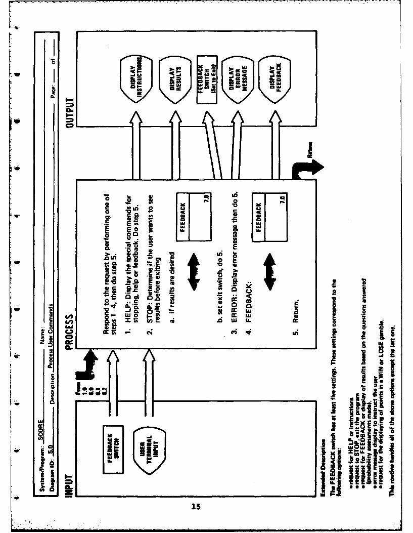
2.2 General opertn Procedures
SCORE is designed to interact with the user by pre-
senting a sequential set of questions and alternative
answers and asking the user to respond by selecting the
correct answer and specifying the degree of certainty in the
form of a probability. The user may optionally enter com-
mand characters (H, F, or S) which will allow the interrup-
tion of the question-answering mode. If the "H" command is
entered, the system will return a list of available commands
and an explanation of their use; the "F" command causes the
output of intermediate results; and the "S" command causes
an exit from the system prior to finishing the question set.
The system is also designed to be generally forgiving
of procedural errors by the user.
2.3 System Logical Flow
SCORE is a hierarchically structured, modular system.The system structure and logical flow lends itself to
3
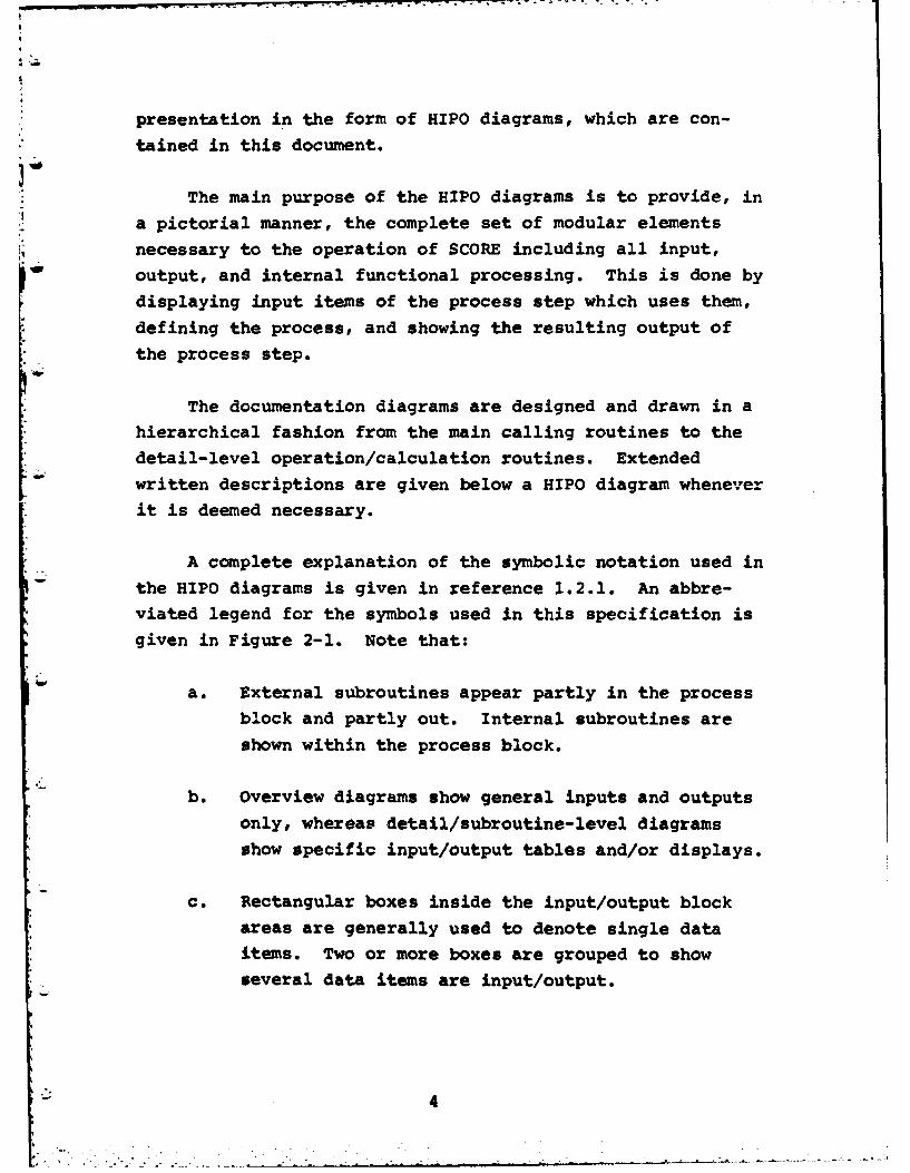
* presentation in the form of HIPO diagrams, which are con-tained in this document.
The main purpose of the HIPO diagrams is to provide, ina pictorial manner, the complete set of modular elements
necessary to the operation of SCORE including all input,
output, and internal functional processing. This is done by
displaying input items of the process step which uses them,
defining the process, and showing the resulting output of
the process step.
The documentation diagrams are designed and drawn in a
hierarchical fashion from the main calling routines to the* detail-level operation/calculation routines. Extended
written descriptions are given below a HIPO diagram whenever
it is deemed necessary.
A complete explanation of the symbolic notation used inthe HIPO diagrams is given in reference 1.2.1. An abbre-
* viated legend for the symbols used in this specification isgiven in Figure 2-1. Note that:
a. External subroutines appear partly in the process
block and partly out. Internal subroutines are
shown within the process block.
b. Overview diagrams show general inputs and outputs
only, whereas detail/subroutine-level diagrams
show specific input/output tables and/or displays.
ce Rectangular boxes inside the input/output block
areas are generally used to denote single dataitems. Two or more boxes are grouped to showseveral data items are input/output.
4

Control
*Data movement Sbotn
-> Pointer
- - - - - > ata efer nceLogical grouping
- ~ of functions
Keyed data arrows
I Function identifiedAMI but not included in
ID Of f-page N.N package
connection arrowsL. J
~DATA
'. General flow of data 'DATA ' Or TEamong subprocesses ITEMII Any general
Subrutie ivoke j* ,,J input or output itemW (Return is made to
calling routine)
Routine receives control ONLINE Input/output medium -
STORAGE includes drum, disk, tape,Routine exitsdikteor returns controlI
Inoraio isly yMAGNETIC Mantcap
Infrmtin dspaybyTAPE input/output mediumDISPLAY online indicators - prompted
by program execution or by ekeyboard input, especially CRT
Figure 2-1LEGEND OF HIPO SYMBOLS

d. Rectangular boxes inside the process block indi-
W cate repetitive subprocesses*
The HIPO diagrams appear in the next section, which
completes the System Specification.
2.4 HIPO Documentation
The HIPO diagram identification numbers and figure
040 numbers used in this section stand alone; i.e., they start
with 1.0, increase hierarchically, and are independent of
the number scheme used to this point in this document.
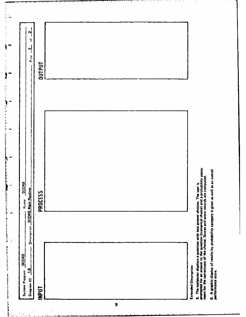
Figure 2-2 is a system structure chart and represents
the overall program logic flow in a visual table of con-
tents. The Visual Table of Contents diagram shows the
hierarchical structure, the functional description labels,
and the diagram (chart) identifiers of functions of SCORE.

U C
0 U
F
C' ., Z;=C=.
?A~a U rI-
qc w 0
LUU
X 02 0At! 0
C: 11C L
C02 U)
C, 0 0
U)LU z
7Z

CP
E c
18 9 a - g
20. 11, at WI
am ma -ewamac
4-. 'o z 0 z*
o 0*
w.6. u. .CL
C.. o
w. COn
E.- E E- a
-o to~- (nw
(I0 0 X~~
00 o oUi 0. c
t ., , U.
0 9 5
0 LU
o -) -~ 0 V 0L
0 0n 1 o %
CL~ &0- e0
oU 0 0 4) 0Os0 S_____________ 20C
E to
C- CU, v .:c
0 1 * rt .L) LU E
0~~ C CL a--L. a- 0
inCi z z82 '
0~0
0 -2L)r o
V)
,C 8
E CD 0IAjh C
K an'
w7
S0C Al
0.0
&vLl 0ia
92

cc -o FA.---------------.--
cU
cc 00Sim16.C
E
go 0%- I -
0
Ni .
CL E
.00
00
_j N- .0 E
qw
W0 0
cc 2-5c'
aLa
w 4- 0.
4-4
Cc C a. Sc N
- -n cV CL
In -ncc00 tou
Uq 2
0~ !a JFC *E
& f I x3
X.,~
10
-. ~~~~~~ .... . .. - - -* -

I Co..
CL
C 0L
L~IA
0 1
UtU.c
0
JEcE XE0 C4 IA%
L !h . -S
CH
IA £0.Its

0 l6 go
~~1wv~~
IC~~~ a.
CLl
c
.20
."*
_ ICcc .2 L
0 1. 04u
0 w. 00.
La Vt 3
Ii ). vj.2 E
14 0
c c122

w On =wlk
c cc
z Ae
0 E
h.0.0
C eli *1CL E* .2
.. 5 *0 0Z
C.- C2
0S5 t
ama El
13

ci
E 0.
S c
c CL
* 0
c CLC.2 'A
t0m
E C
* 0oj c
C .~ 0
.2 0 0 U.- f
F .cwew 2
0.0(ICE
CLI
a..
I.L
uu [P
0i*
E 0"
0 I.5 0 o
aLL 0o U 0 CC u
I-j
0 o0
r x
;w r u
Ul see *0~fli. i~ C LU.5

Ls Intoo
II II
a.r LAJ
CL?A- -r4-c
Mie
CD C-
00aa a lu
w.as
Go
'4 E 1.

LD I-.- Eina t;CO C1 '..- 10:1. MCI-
0. x
CD
IIt
::A! *rcw~~ - *W.L
0- =0 L 0 r'ii n d2. --CC a9 9 a*
0 a. u * =1. so ..
- 1. 0 C. a
cr *- L
xC E .~I
£w a ~S A~ C! .
.4 0
0
-j 11111 ' 4uiI
asa
17

.~ ~ ~ 1 us -1 . ..
C-D
I-l
7ZI0I
C.,
21o to. to[Jo S~
E E44 ORI I-
- £
c*m
E EI
W -o-
U) ~ a nowu..
4A~ W

L IWa ia I ma tCO mw1
I.-_- ,.U) C
liiw SOc
b.I eli -"M' -
co
. *0.
4-.- ,'' " '€ ' k~
O, . . £ '-a;(I ii iti, 1-- °)
131
C~ h.2~ fI.~iULii iii j~I~j.06
- ~ ~ . fJ .ECL9