PARTNERS AT THE LAST MILE: RETAILERS, BANKING AGENTS, AND INSURANCE COMPANIES.

Advanced Engineering | Infrastructures | Agents & Partners

2 SDEA Solutions is a technical
consultancy company with
expertise providing first class
design & engineering services.
SDEA counts with an excellent
track record and reputation in
the market delivering solutions
to a range of industries such as,
Oil&Gas, Maritime, Offshore,
Transportation and energy.
Our three main action areas are
Advanced Engineering
Calculations, Infrastructures
designs mainly for Railway
electrifications and BIM for lineal
infrastructures, and acting as
Sales representative for
RappMarine and STADT, both
Norwegian companies.
Our Engineers form a high skilled
team that share a passion for
working on international
projects, technical challenges
and using the most advanced
Engineering resources to help
our clients reach their goals,
delivering high performance
products that are safe, reliable
and cost-effective.
Three Locations
Vigo - Galicia (Spain)
Haro – La Rioja (Spain)
Nottingham (UK)
Advanced Engineering | Infrastructures | Agents & Partners
Team profile

3
SDEA Solutions – About us
Technical consultancy company specializing in providing engineering solutions
Offering innovative and simulation driven analysis to increasingly complex and multi-
physics engineering challenges faced by our clients
Advanced Engineering
– Finite Element Analysis (FEA)
– Computational Fluid Dynamics (CFD)
– Thermal – Mechanical & Process Engineering
– Heavy lifting tools & custom made solutions
– Extensive background on International standards
Software
— FEA: Ansys Mechanical, Nastran, Abaqus,
— CFD: Fluent, CFX, STAR CD, Open Foam
— Thermal: HTRI, Own development datasheets
— Structural Analysis: PV Elite, Dlubal, Cype, Robot
— CAD: Microstation, Autodad, SolidWorks, Tekla

4
FEA Capabilities
• Linear-Elastic stress analysis• Thermo-mechanical analysis• Non-linear plastic collapse analysis• Fatigue and fracture mechanics• Seismic and Vibration Analysis• ASME, API, PD and UNE analysis
FEA: Core Technical Capabilities

5
Design and FEA calculation for marine equipments – SWL 600 Tn
High order elements combining
HEX20 and TET10
Technical Capabilities: FEA
Fatigue damage for different
assumed loading cycles

6
3000 T Lifting appliances testing tool [upgrade to 6000T]
Lifting Beam: SWL 300 / 500 Tn
Services: Tooling design
7
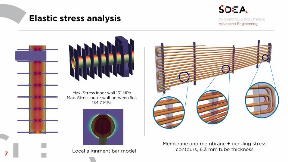
Elastic stress analysis
Membrane and membrane + bending stress
contours, 6.3 mm tube thickness
Max. Stress inner wall 131 MPa
Max. Stress outer wall between fins
134.7 MPa
Local alignment bar model

8
Elastic stress analysis
Temperature results
Temperature difference between interior and exterior
surface for the whole thermal cycle.
The maximum temperature difference occurs 2 times per
cycle so number of cycles are doubled
Tube-tubesheet weld thermal shocking failure
Thermal shocking

9
Compact heat exchangers
Operational thermal cycle fatigue analysis including cfd to get the operational
temperature field and FEA to obtain the related thermal stress field

10
Microturbines-Recuperator design
Thermal CFD local models to simulate fin heat
exchangeGeometry optimization

11
Oil to Salt heat exchanger
OIL TO SALT HEAT EXCHANGER FATIGUE UNDER ASME VIII DIV 2 REQUIREMENTS FOR
SOLAR POWER PLANT

12
Process Engineering Capabilities
Thermo-hydraulic and mechanical design of heat exchangers:• Shell and tubes, Air-cooled, Cross-flow (recuperators/economizers), Furnaces and boilers
Design of process equipment (unit operations):• Distillation, Absorption / Stripping, Adsorption, Multiphase separators
Process engineering of chemical and energy plants:• Conceptual and basic engineering. Feasibility studies• Detailed engineering of oil refining plants• Detailed engineering of natural gas treatment plants

13
Equipment design
DISTILLATION:• Tray-columns (perforated trays, valves and bubble caps)• Packed-columns (random packing: rings)• Packed-columns (structured packing)
ABSORPTION/STRIPPING:• Tray-columns (perforated trays, valves and bubble caps)• Packed-columns (random packing: rings)• Packed-columns (structured packing)
MULTIPHASE SEPARATORS:• Gas / vapour vs. solid (cyclones, bag filters)• Gas / vapour vs. liquid (decanters, demisters)• Liquid vs. solid (clarifiers, hydrocyclones)• Light liquid vs. heavy liquid (decanters)• Gas / vapour vs. light liquid vs. heavy liquid (3 phases)

14
Thermal Engineering
SHELL AND TUBES - TEMA/API 660/HEI:• Oil-molten salts equipment for thermal energy storage• Steam generation systems• Thermosyphon reboilers (vertical, horizontal) • Feedwater heaters (FWH)• Steam surface condensers• Bayonet vaporizers, hairpin, doble pipe, tank coils
AIR-COOLED - API 661:• Process coolers / condensers• Steam condensers for thermal power plants (A-frame)
FURNACES - API 560:• Process direct fired heaters• Firetube and watertube boilers

15
Thermal fatigue – Oil and Gas
Thermal fatigue project following ASME VIII div 2 requirements for oil and gas

16
CFD: Core Technical Capabilities
Fluid-dynamics
• Aerodynamic/hydrodynamic optimisation
• Flow assurance oil & gas
• Turbulence modelling
• Discharge coefficient calculations
• Particle transport and Erosion analysis
• Conjugate Heat Transfer modelling
• Flow-induced vibration and turbulence noise
• Joule-Thompson cooling
Choke Sand Erosion Contours Pipework Sand Erosion Fatigue Analysis

17
CFD: Flash Tank
Flow path lines here illustrate the general flow path followed by the
fluid from the inlets up to the outlets.
As expected, a vertical flow is initially generated in the tank and the
entrance to the outlet vent, however this effect diminishes by the
time the flow reaches the outlet.
Flow path lines inside a flash
tank and discharge zone

18
CFD: Turbine Condenser
Mesh detail for the half symmetry model Pressure vs. Velocity relation
Velocity along vertical lines Velocity contours

19
Wind effects on masts

20
Piping example analysis
Erosion analysis of a subsea flow meter Flow induced vibration (fiv)
• Assessing a cone flowmeter to determine likelihood of fatigue
due to FIV
• CFD used to simulate the turbulent flow structures and fluid
forcing signal
• Coupled with an FEA model of the structure to assess
structural response
Studies using coupled cfd/fea

21
HVAC for vehicles

22
CFD: Coaches Crosswind

23
Iso-surfaces of volume-fraction showing the water-
free surface flow velocity through a spillway
Relevant Project
Using numerical simulations to
characterise likely failure scenarios

24
Civil & CAD design, Point Clouds

25
DNV 2.22 Lifiting appliances
DNV RP-C203 – Fatigue design of offshore steel
strectures
DNV RP-F112 – Design of duplex stainless steel subsea
equipment
exposed to cathodic protection
DNV RP-F113 Pipeline subsea repair
DNV RP-F-101 – Corroed pipelines
DNV GL-RP0034 – Steel Forging for subsea application
DNV-OS-C101 – Submarine pipeline systems
DNV-OS-F101 – Corroded pipelines
DNV 2.7-3 – offshore containers
DNV RP C208 – Structural capacity by non-linear analysis
NACE – MR -0175 General Principles for selections
of cracking resistance materials
FEM 1001 - RULES FOR THE DESIGN OF HOISTING
APPLIANCES
BV-NI-184 Lifting appliances
ASME Div2 Sec VIII Rules for construction of pressure
vessels
ASME B16.5 – Pipe flanges and flanget fittings
ASME B31.3 & B31.9 – Piping code sections
API- RP-2A Recomended Practice for planning
designing and constructed fixed offshore platform
API 6A - Specification for Wellhead and Christmas Tree
Equipment
PD-5500 - Specification for unfired fusion welded
pressure vessels
NORSOK M-630 – Material data for piping
Standards & Rules

26
Clients & Sectors

InfrastructuresAdvanced EngineeringAgents & Partners
Spain Office
Gran Vía, 161 | Vigo
+34 653 942 425
UK Office
Kegworth, Derby
+44 (0) 743 585 9526
www.sdeasolutions.com
We look forward to hearing from you!