
Advanced EMU Portable Life Support System (PLSS) and ... · Advanced EMU Portable Life Support...
18
American Institute of Aeronautics and Astronautics 1 Advanced EMU Portable Life Support System (PLSS) and Shuttle/ISS EMU Schematics, a Comparison Colin Campbell 1 NASA Johnson Space Center, Houston, Texas, 77058 In order to be able to adapt to differing vehicle interfaces such as suitport and airlock, adjust to varying vehicle pressure schedules, tolerate lower quality working fluids, and adapt to differing suit architectures as dictated by a range of mission architectures, the next generation space suit requires more adaptability and robustness over that of the current Shuttle/ISS Extra-vehicular Mobility Unit (EMU). While some features have been added to facilitate interfaces to differing vehicle and suit architectures, the key performance gains have been made via incorporation of new technologies such as the variable pressure regulators, Rapid Cycle Amine swing-bed, and Suit Water Membrane Evaporator. This paper performs a comparison between the Shuttle/ISS EMU PLSS schematic and the Advanced EMU PLSS schematic complete with a discussion for each difference. Nomenclature AEA: assured EMU availability AISI: American iron and steel institute BLDC: brushless direct current BSLSS: buddy secondary life support system BTU/hr: BTU per hour BTU: British Thermal Unit CAMRAS: CO2 and moisture removal amine swingbed CASEO: cabin air seperator for EVA oxygen CO 2 : carbon dioxide CON: controller COPV: composite over-wrapped pressure vessel COTS: commercial off-the-shelf CPV: combination purge valve CWCS: caution warning and control system CxP: Constellation Program DCM: display and control module DCS: decompression sickness DP: differential pressure EMU: extravehicular mobility unit ETDP: EVA Technical Development Program EV: extravehicular EVA: extravehicular activity F/P/S: fan-pump-seperator FM: flow meter FMEA: failure modes effects analysis FSA: feedwater supply assembly H2O: water HEFT: human exploration framework team HX: heat exchanger ISS: International Space Station 1 PLSS Lead, Space Suit and Crew Survival Systems Branch, Crew and Thermal Systems Division, 2101 NASA Parkway, Houston, Texas, 77058, Mail code EC5. https://ntrs.nasa.gov/search.jsp?R=20120009158 2018-05-27T18:46:37+00:00Z
Transcript of Advanced EMU Portable Life Support System (PLSS) and ... · Advanced EMU Portable Life Support...

American Institute of Aeronautics and Astronautics
1
Advanced EMU Portable Life Support System (PLSS) and Shuttle/ISS EMU Schematics, a Comparison
Colin Campbell1 NASA Johnson Space Center, Houston, Texas, 77058
In order to be able to adapt to differing vehicle interfaces such as suitport and airlock, adjust to varying vehicle pressure schedules, tolerate lower quality working fluids, and adapt to differing suit architectures as dictated by a range of mission architectures, the next generation space suit requires more adaptability and robustness over that of the current Shuttle/ISS Extra-vehicular Mobility Unit (EMU). While some features have been added to facilitate interfaces to differing vehicle and suit architectures, the key performance gains have been made via incorporation of new technologies such as the variable pressure regulators, Rapid Cycle Amine swing-bed, and Suit Water Membrane Evaporator. This paper performs a comparison between the Shuttle/ISS EMU PLSS schematic and the Advanced EMU PLSS schematic complete with a discussion for each difference.
Nomenclature AEA: assured EMU availability
AISI: American iron and steel institute
BLDC: brushless direct current BSLSS: buddy secondary life support system BTU/hr: BTU per hour BTU: British Thermal Unit CAMRAS: CO2 and moisture removal amine swingbed
CASEO: cabin air seperator for EVA oxygen
CO2: carbon dioxide CON: controller COPV: composite over-wrapped pressure vessel
COTS: commercial off-the-shelf CPV: combination purge valve CWCS: caution warning and control system CxP: Constellation Program DCM: display and control module DCS: decompression sickness DP: differential pressure EMU: extravehicular mobility unit ETDP: EVA Technical Development Program EV: extravehicular EVA: extravehicular activity F/P/S: fan-pump-seperator
FM: flow meter FMEA: failure modes effects analysis FSA: feedwater supply assembly H2O: water HEFT: human exploration framework team HX: heat exchanger ISS: International Space Station
1 PLSS Lead, Space Suit and Crew Survival Systems Branch, Crew and Thermal Systems Division, 2101 NASA Parkway, Houston, Texas, 77058, Mail code EC5.
https://ntrs.nasa.gov/search.jsp?R=20120009158 2018-05-27T18:46:37+00:00Z

American Institute of Aeronautics and Astronautics
2
IV: intravehicular IVA: intra-vehicular activity LCVG: liquid cooling and ventilation garment LEO: low earth orbit LiOH: lithium hydroxide
LLB: long life battery
ME: membrane evaporator MEMS: micro-electro-mechanical system MSPV: multiposition suit purge valve NC: normally closed NH3: ammonia
O2: oxygen OML: outer mold line OPS: oxygen purge system ORCA: oxygen recharge compressor assembly PLSS: Portable Life Support System POR: primary oxygen regulator POV: primary oxygen vessel PP: pitot probe PPRV: positive pressure relief valve PWM: pulse-width-modulated
QD: quick disconnect RCA: rapid cycle amine RRCA: root cause/corrective action RTD: resistance temperature detector RV: relief valve SIP: suitport interface plate SOA: secondary oxygen assembly SOP: secondary oxygen pack SOV: secondary oxygen vessel SOV: solenoid operated valve SSA: space suit assembly SWME: spacesuit water membrane evaporator TCC: trace contaminant control TCV: thermal control valve UTRC: United Technologies Research Center
WSTF: White Sands Test Facility
I. Introduction
In the 30 years since the Shuttle Extravehicular Mobility Unit (EMU) began operations, the crew vehicles have
changed little from the EVA suit perspective. The Shuttle changed from internal to external airlocks with the same basic interfaces and the International Space Station (ISS) was assembled with the EMU in mind, hence maintaining the same vehicular interfaces and even using an airlock design based on the Shuttle airlock. However, with the Shuttle retired and Agency planning efforts like the Human Exploration Framework Team (HEFT) indicating that vehicles and missions will likely differ from the familiar Shuttle and airlock, a new adaptable Portable Life Support System (PLSS) is mandated. This new PLSS, referred to in conjunction with the Space Suit Assembly (SSA) as the Advanced EMU (AEMU), will need to be capable of functioning when: attached to differing configurations of SSA, operating with an airlock style vehicle, operating with a Suitport configured vehicle, and across a range environments from Low Earth Orbit (LEO) to the Moon and Mars and a number of potential destinations in-between. The approach for the AEMU going forward is to construct a capability rather than a specific solution for a particular mission. This capability, an armoire of SSA configurations with appropriate life support capabilities, can then be adapted to match a particular mission set or vehicle as needed. In order to address and construct a design going forward, it is often wise to examine historical designs for practical knowledge to apply in the effort. This

American Institute of Aeronautics and Astronautics
3
paper will examine some of the driving requirements that mandate upgrades in functionality and then with emphasis on the schematics, compare the Advanced EMU to the Shuttle/ISS EMU with references to the Apollo EMU. The Shuttle/ISS EMU was designed and has been operated with a single LEO-based SSA design that utilized the existing helmet from the Apollo A7LB spacesuit. This allowed for some simplications such as motor speed control with a single set speed of ~19.7kprm. In contrast, at its current phase of development, the AEMU is developing SSA configurations with multiple configurations including helmet design. These differing suit configurations alter the requisite ventilation flow rate and allowable operating pressures that the PLSS must control. The SSA variability is not the most significant impact on the PLSS design, rather the vehicle interface variability between airlock and Suitport has that effect. The airlock is a well known vehicle interface that has been known and in use for decades and is the manner in which the current Shuttle/ISS EMU interfaces with the ISS and formerly the Space Shuttle. In this case, when the suited crew make the transition from Intra-Vehicular Activities (IVA) to Extra-Vehicular Activities (EVA), they are encompassed by the airlock as the entire surrounding environment is depressed to vacuum so that they may exit the vehicle. This enables things such as local ambient pressure referencing to function nominally from the PLSS packaging perspective as the vented PLSS is referencing the same environment to which the suited crew is exposed. For Suitport, however, that is not the case. For Suitport, the suit itself is part of the vehicle pressure barrier with the pressure boundary imposed at the Suitport Interface Plate (SIP). This pressure boundary means that the PLSS, which resides on the back of the suit, back inside the Vestibule, may be at a different ambient reference pressure from that of the SSA which the PLSS is trying to control. These implications will be discussed at greater depth later when the AEMU PLSS functions are described. In holding with the operating environment ranges for the AEMU varying between Earth, to LEO, to Lunar, to Mars, and elsewhere, one of the significant differences between these environments is the gravity field. While the current Shuttle/ISS EMU successfully operates between ground vacuum chamber testing and LEO, the significance of the varied g-fields has the affect of removing design options that were available in the Apollo EMU such as vent ports and drain ports that relied upon g-field driven separation of multi-phase fluid loops. Other environmental variances such as radiation, MMOD, dust, etc do not necessarily drive the PLSS design but must be addressed in the future design and development as the fidelity increases. The design of the AEMU and specifically the PLSS is driven by some key assumptions with respect to capabilities and performance:
1. AEMU is an EVA specific design, not a combined LEA and EVA system like the Apollo EMU but more like th Shuttle/ISS EMU. This assumption holds greater impact for the SSA than the PLSS, but does have implications for the PLSS enabling for optimizations of the system package because the Secondary Oxygen Assembly (SOA) does not need to be modular to support a LEA configuration EVA suit as it did in the initial Operations Concepts(8) for the Constellation Program (CxP).
2. AEMU is capable of interfacing and operating with airlock and Suitport equipped vehicles. This provides the capability to operate with all of the known potential vehicle configurations for EVA spacesuits across a wide range of potential missions.
3. AEMU is capable of performing for 8hrs in fully autonomous mode. This is longer than the original configurations of the Apollo EMU prior to the -7 PLSS which was extended to this length in capability for Apollo 15-17. It is also longer than the original Shuttle EMU capability of 7hrs which was extended to 8hrs as the Shuttle/ISS EMU.
o Apollo EMU Duration(5,7) 8hrs @ 930 BTU/hr, 6hrs @ 1200 BTU/hr, 5hrs @1600 BTU/hr
o Shuttle/ISSS EMU Duration(3) 7hrs @ 1000 BTU/hr
o AEMU duration 8hrs @ 1200 BTU/hr
4. AEMU is capable of performing 100 EVAs during mission operations. This number was originally driven
by the CxP Lunar scenarios which assumed as many as 100 EVAs over a 6 month period on the Lunar surface. The number has remained but is not considered a driving requirement given the current phase of AEMU development; the hardware capabilities will be assessed and the 100 EVA may be reduced at some point in the future. The 100 EVA goal, is challenging and significantly higher than the current Shuttle/ISS EMU certification of 25 EVAs between invasive maintenance on the ground.
American Institute of Aeronautics and Astronautics
4
5. AEMU is capable of operating in environments ranging from LEO, to Lunar, to Mars and locations in between. At the particular level of development, the AEMU has not yet addressed environmental performance beyond ambient pressure in a single g-field but the intention is certainly to refine the requirements for all of these locations and to evaluate the system design with respect to them. It is also important to note that the designs to be discussed herein focus less on the Mars performance and more on the LEO to Lunar capabilities, meaning that while it may be capable of functioning in the Mars environment, it may not be the ideal candidate when considered with a particular mission architecture.
6. AEMU approach to reliability is similar to that used for the Apollo EMU and the Shuttle/ISS EMU. The system is designed as a “fail safe” system which can tolerate a single failure with loss of an EVA but not loss of life. This implementation approach is similar to the previous EVA PLSS designs given that the volumetric/mass constraints are also the similar. Since the AEMU Outer Mold Line (OML) currently dictated by the developmental Suitport interface is larger than that permitted for the Shuttle EMU which was driven by an operations scenario requiring a suited crewmember to transfer between decks on the Shuttle3, the AEMU has more flexibility to selectively add more capability/redundancy than the Shuttle/ISS EMU. The Failure Modes Effects Analysis (FMEA) process successfully used for both the Shuttle and ISS Programs is being used on the AEMU design to assist the development decisions regarding the addition of redundancy although it is not anticipatated that a “fail operational” system will ever be achievable within the current mass/volume constraints.
These goals, together, yield an adaptable AEMU PLSS architecture…a capability, that is able to support most of the missions presently being considered.
II. Overview of Baseline AEMU Schematic To begin the comparison between the AEMU PLSS and that of the Shuttle/ISS EMU and to an extent, the Apollo EMU, first, a description of the AEMU PLSS is necessary. The AEMU PLSS pneumo-hydraulic schematic consists of the following basic loops(9):
American Institute of Aeronautics and Astronautics
5
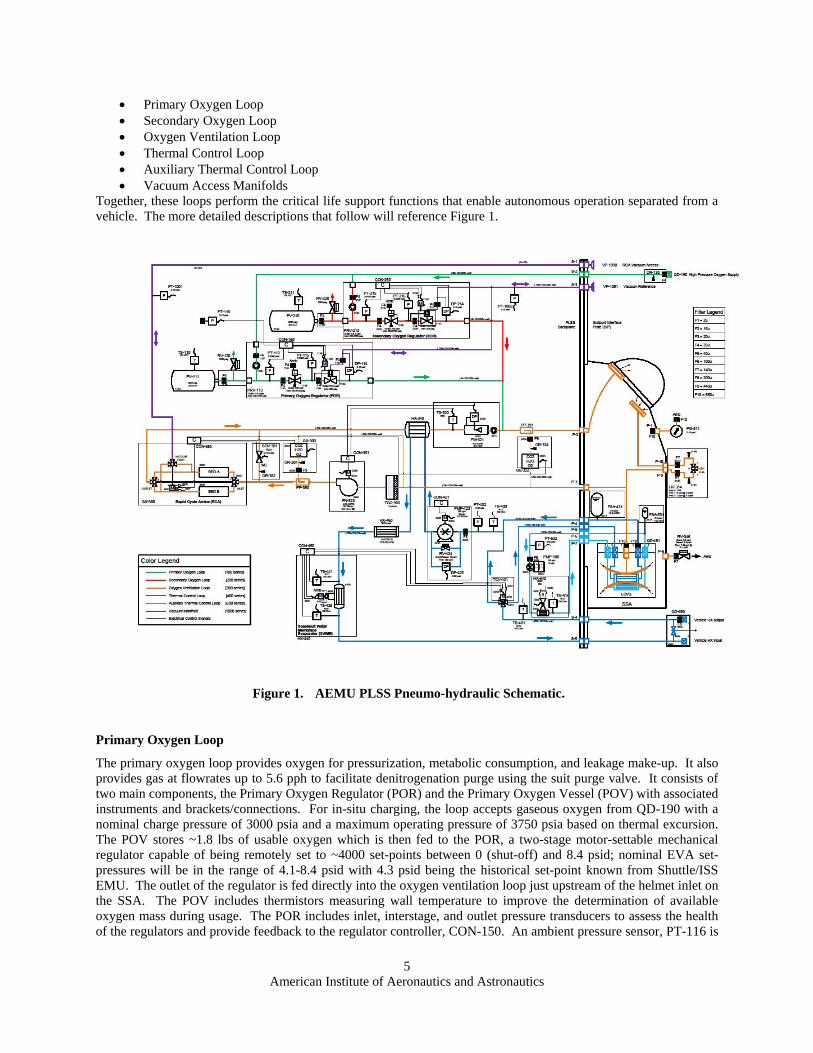
Primary Oxygen Loop Secondary Oxygen Loop Oxygen Ventilation Loop Thermal Control Loop Auxiliary Thermal Control Loop Vacuum Access Manifolds
Together, these loops perform the critical life support functions that enable autonomous operation separated from a vehicle. The more detailed descriptions that follow will reference Figure 1.
Figure 1. AEMU PLSS Pneumo-hydraulic Schematic.
Primary Oxygen Loop
The primary oxygen loop provides oxygen for pressurization, metabolic consumption, and leakage make-up. It also provides gas at flowrates up to 5.6 pph to facilitate denitrogenation purge using the suit purge valve. It consists of two main components, the Primary Oxygen Regulator (POR) and the Primary Oxygen Vessel (POV) with associated instruments and brackets/connections. For in-situ charging, the loop accepts gaseous oxygen from QD-190 with a nominal charge pressure of 3000 psia and a maximum operating pressure of 3750 psia based on thermal excursion. The POV stores ~1.8 lbs of usable oxygen which is then fed to the POR, a two-stage motor-settable mechanical regulator capable of being remotely set to ~4000 set-points between 0 (shut-off) and 8.4 psid; nominal EVA set-pressures will be in the range of 4.1-8.4 psid with 4.3 psid being the historical set-point known from Shuttle/ISS EMU. The outlet of the regulator is fed directly into the oxygen ventilation loop just upstream of the helmet inlet on the SSA. The POV includes thermistors measuring wall temperature to improve the determination of available oxygen mass during usage. The POR includes inlet, interstage, and outlet pressure transducers to assess the health of the regulators and provide feedback to the regulator controller, CON-150. An ambient pressure sensor, PT-116 is

American Institute of Aeronautics and Astronautics
6
not physically attached to the POR but provides a feedback signal to CON-150 denoting the ambient PLSS pressure, which for Suitport, would be the vestibule pressure.
Secondary Oxygen Loop
The secondary oxygen loop provides the redundancy for all oxygen and ventilation loop life support functions via an open loop oxygen ventilation flow through the suit purge valve. The loop provides oxygen for pressurization, metabolic consumption, leakage make-up, carbon dioxide washout, as well as, humidity and trace contaminant control. Like the primary oxygen loop, the secondary oxygen loop consists of two main components, the Secondary Oxygen Regulator (SOR) and the Secondary Oxygen Vessel (SOV) with associated instruments and brackets/connections. For in-situ charging, the loop accepts gaseous oxygen from QD-190 with a nominal charge pressure of 3000 psia and a maximum operating pressure of 3750 psia based on thermal excursion. The SOV stores ~1.8 lbs of usable oxygen which is then fed to the SOR, a two-stage motor-settable mechanical regulator capable of being remotely set to ~4000 set-points between 0 (shut-off) and 8.4 psid with a nominal set pressure of 3.7 psid. For long term, this may be simplified to a single mechanical set pressure of ~3.7 psid with remote actuation but the SOR presently has the same capabilities as the POR for commonality, cost, and operations concept evaluations. The SOR operates as a nested regulator below the POR nominal set range of 4.1-8.1 psid for EVA conditions. When the POR can no longer maintain the set pressure in the 4.1-8.4 psid range and the pressure drops to 3.7-3.9 psid, the SOR will begin to regulate and hold the suit pressure at the specified set-point. The outlet of the regulator is fed directly into the oxygen ventilation loop just upstream of the helmet inlet on the SSA. The SOV includes thermistors measuring wall temperature to improve the determination of available oxygen mass during usage. The SOR includes inlet, interstage, and outlet pressure transducers to assess the health of the regulators and provide feedback to the regulator controller, CON-250.
Oxygen Ventilation Loop
The oxygen ventilation loop provides for CO2 washout, humidity control, trace contaminant removal, and SSA inlet gas temperature control. To accomplish this, a centrifugal fan is utilized to move the loop at flowrates variable between 3-8 acfm with nominal set-points between 4.5-6 acfm. The outlet of the fan (FN-323) heads towards the Rapid Cycle Amine (RCA) swing-bed; before reaching the swing-bed, a small gas stream (~100 sccm) is picked up by a pitot probe (PP-390) and fed through a filter and orifice assembly and then into the RCA inlet gas sensor (GS-300) which quantifies the species of H2O, CO2, and O2 heading into the RCA inlet; the sample gas is then fed back to the inlet of the TCC using the bulk of the fan head rise less the TCC pressure drop to move the sample gas in closed loop. The gas continues into the inlet of the RCA (GX-380) where the adsorbing bed of the RCA removes CO2 and H2O and then feeds it back to the fan inlet. The RCA is a two bed (A bed, B bed) amine-based swing-bed system in which one bed is adsorbing CO2/H2O while the other bed is desorbing CO2/H2O to vacuum. When the CO2 readings from the helmet inlet gas sensor (GS-322) reaches a determined value depending on the chosen algorithm, the RCA controller swings the bed by driving a stepper motor-controlled rotary ball valve to equalize the two beds and then transition such that the bed that just completed desorb is placed into the ventilation loop stream to begin its adsorb half-cycle. During the bed transition, the flow through the ventilation loop is maintained as the controller (CON-350) commands the RCA bypass solenoid valve (SOV-381) to open momentarily; the Normally Closed (NC) valve is then closed by the controller when the bed transition is complete. Under conditions in which the gas sensor (GS-322) has failed, the RCA controller will revert to a conservative time-based cycle which is designed to remove enough CO2 for a high metabolic rate. The outlet from the RCA moves into the ventilation loop heat exchanger (HX-340) where the heat added by the fan earlier in the loop is removed and cool dry gas exits where the ventilation loop temperature sensor (TS-320) determines the gas temperature prior to entering the V-coneTM style flow-meter2 and check valve (FM-321) then onto the helmet inlet in the SSA. The check valve is present to ensure that under failure conditions in which the suit is operating in open loop purge mode, that the regulator flow from the POR/SOR is directed to the helmet inlet rather than permitted to back-flow the ventilation loop; this is required for the open loop flow to maintain adequate flow through the helmet. The volumetric flowrate computed from FM-321 using the inlet temperature, pressure, and delta-pressure is fed back to the fan controller to ensure that the actual required volumetric flowrate for the attached specified suit configuration is provided by the fan (FN-323). Just before the gas enters the helmet, a pitot probe (PP-391) pulls a small stream of gas (~100 sccm)
2 V-cone is a Trademark of McCrometer, Inc.

American Institute of Aeronautics and Astronautics
7
through a sample line with a filter and orifice back to the helmet inlet gas sensor (GS-322) which then quantifies the species of H2O, CO2, and O2; the sample gas is then returned to the inlet of the Trace Contaminant Control (TCC) assembly using the pressure drop across the spacesuit to drive the flow. The clean, dry, low humidity, low CO2 gas is fed into the SSA and onto the oro-nasal region of the crew member where they inspire it, and expire high humidity, high CO2 gas which is flushed downward by the inlet gas flow and out to the extremities where pick-up tubes on the Liquid Cooling and Ventilation Garment (LCVG) located typically at the elbows and feet, return the gas back to the PLSS for processing. This return gas is fed directly into the TCC assembly which filters it for particulate and removes trace contaminants with specially treated activated charcoal. The gas then leaves the TCC and heads directly into the fan (FN-323). Additional components located on the SSA include the Positive Pressure Relief Valve (PPRV) and Multi-position Suit Purge Valve (MSPV). The PPRV protects the suit and oxygen ventilation loop from over-pressurization in the event that either the POR or SOR fail open; it would also protect the suit during an airlock depress where the ambient pressure decrease is faster than the combined suit leakage, RCA ullage loss, and metabolic consumption. The MSPV enables a nominal function for denitrogenation purge that occurs at the beginning of every EVA as the suit environment is transitioned from a mixed gas to a single gas oxygen environment. The two onboard gas sensors (GS-322 and GS-300) will be used to monitor the purge transition directly via the oxygen concentration measurement. The MSPV also enables the redundant life support function of the secondary oxygen loop in which the valve is actuated to enable the open loop purge mode needed.
Thermal Control Loop
The thermal control loop performs primary thermal control for the suited crewmember and the PLSS. The loop is designed and sized to accommodate metabolic waste heat, electronics waste heat, and environmental heat leak in hot environments with the maximum rejection design point of 810W. To accomplish this, the loop includes a Feedwater Supply Assembly (FSA) which utilizes the suit ventilation loop pressure to compress the compliant bladder and exert slightly less pressure on the thermal loop fluid. The FSA utilizes variable compliance bladders that exaggerate the pressure response with ~ 1 lb of feedwater remaining; this is detected by the drop in pressure at PT-432 at the pump inlet. This is not the primary method for tracking water as a consumable as the SWME water utilization will perform that function, rather it is a back-up in the event that leakage or other failure modes render the water utilization computation inaccurate. Once the fluid has been pressurized by the FSA, it travels out of the SSA and into the PLSS where the LCVG outlet temperature sensor (TS-400) measures the water temperature via an insertion style RTD. Next, the fluid contacts the thermal control loop pressure sensor (PT-432) which measures the absolute loop pressure via a media isolated MEMS strain gauge just prior to the pump inlet. The pump (PMP-423) moves the entire loop via a gear-based positive displacement pump powered by a BLDC motor running at a speed set by the pump controller (CON-451). Typical set-point will be ~200 pph but can be varied as needed in the future. Since the pump is capable of generating pressures in a dead-head condition that are higher than the remainder of the loop can tolerate, a pump bypass RV (RV-424) is placed across the outlet to inlet of the pump to limit the outlet pressure rise in the event of obstructed flow. A differential pressure sensor (DP-425) is located across the outlet to inlet of the pump as well and measures the differential pressure rise of the pump via a dual-sided media isolated sense cavity referenced to a MEMS strain gauge via silicone hydraulic fluid. From the pump outlet, the fluid travels through the ventilation loop heat exchanger (HX-340) where it picks up heat from the ventilation loop and allows the ventilation loop to knock down the gas temperature headed to the helmet after fan work is imparted. After leaving the ventilation loop heat exchanger, the fluid then moves to the avionics coldplate, a centralized heat sink for the main set of avionics in the PLSS. After picking up heat from the coldplate, the fluid moves into the Suit Water Membrane Evaporator (SWME) which directly cools the fluid by vaporization of some amount of the fluid across a hydrophobic membrane wall with the rate and consequently, the heat flux controlled by varying the back-pressure via positioning of a poppet-style valve using a stepper-based linear actuator. The SWME controller (CON-450) measures the inlet temperature (TS-441) and the outlet temperature (TS-439) and combines that with data from the pump speed as needed to compute utilization. The outlet temperature is used as the feedback to check against the set-point for the SWME controller which then drives the stepper-based linear actuator based on a defined algorithm to a set position; this process is continually performed to maintain the set-point with variable heat loads. Based on the chosen thermal control algorithm, the set-point itself may be varied along with TCV position to affect a particular crewmember comfort setting. The SWME performs one additional critical function as the fluid passes through the hollow-fiber membrane bundle, it removes any free gas in the system; this enables the system to be primed and wetted from dry, to remove incidental bubbles that could be introduced with mating/demating of loop QDs, and bubbles that could evolve from dissolved gases coming out of solution during reduced pressure operations.

American Institute of Aeronautics and Astronautics
8
From the outlet of the SWME, the fluid flows to the vehicle interface QD (QD-490) which enables vehicle supplied cooling during preEVA/postEVA or contingency operations. The QD possesses a closed-when-mated cross-flow path that acts to allow flow through the loop when the vehicle umbilical is not present and forces flow out through the vehicle when the umbilical is present and mated. The fluid then returns from the vehicle through the QD and enters the Thermal Control Valve (TCV) which is positioned by the TCV controller (CON-452) via a stepper motor. The position can be dictated manually by the crew through interfaces on the suit or can be set automatically via an auto-cooling control algorithm working in conjunction with the SWME set-point. The TCV is a two-outlet diverting valve with varies between full flow to the SSA and LCVG to full flow in the bypass leg within the PLSS and several set-points in-between dictated by how the stepper motor is driven (half-step, micro-step, etc). On the SSA inlet (LCVG inlet) leg, a temperature sensor (TS-401) detects the fluid temperate via an insertion probe RTD. This temperature can be used in conjunction with the LCVG outlet temperature and TCV position to compute metabolic rates for the suited crewmember; it can also be used as the feed-back signal along with TCV position for an auto-cooling control algorithm. Once the flow passes the LCVG inlet temperature sensor, it passes into the SSA traveling through the LCVG picking waste metabolic heat and environmental heat leak before returning to the FSA to start the loop over-again. The flow through the LCVG bypass leg skips the LCVG inlet and flows directly back to the pump inlet. This enables a full bypass configuration which shuts off all cooling flow to the crewmember when in Full Hot on the TCV.
Auxiliary Thermal Control Loop
The auxiliary thermal control loop provides redundancy for the primary thermal control loop life support functions but at diminished capability designed to support an EVA abort to the vehicle safe haven. In order to accomplish this function, the auxiliary thermal control loop consists of a small Feedwater Supply Assembly (FSA) of similar construction to the primary FSA but sized for the reduced duration. In order to detect a leakage failure mode from the system the auxiliary FSA also includes the variable compliance bladder approach which amplifies its response nearing the end of the discharge as read by PT-532. Also similar in function to the primary FSA, the auxiliary FSA provides pressure to the auxiliary thermal loop via compression of a compliant bladder using suit pressure which could be as low as 3.7 psia. The fluid loop is fully redundant to the primary thermal loop in order to eliminate the single point failure of fluid leakage disabling both the primary and redundant functions. The pressurized fluid travels from the auxiliary FSA to the auxiliary pump (PMP-500) which is manually actuated by the crewmember in response to a failure just as the suit purge valve is used to convert the suit to open loop flow in the event of a ventilation loop failure, but in this case by a switch. At the auxiliary pump inlet, the auxiliary thermal control loop pressure sensor (PT-532) measures the absolute loop pressure via a media isolated MEMS strain gauge; this is utilized for both low feedwater detection as well as cavitation condition detection. When the auxiliary pump is actuated, it moves the fluid through the thermal loop at ~100 pph. The auxiliary pump is powered by a BLDC motor operating directly off a dedicated battery. The fluid exiting the pump then travels to the Mini-Membrane Evaporator (Mini-ME) where in similar fashion to the primary unit, a reduced bundle size of hydrophobic hollow fibers cools the fluid passing through by evaporating some of the fluid through the membrane walls to reduced pressure. Unlike the primary SWME, the Mini-ME has a single set-point which is controlled by a solenoid powered gate valve that opens from the same switch and battery power as that driving the auxiliary pump. Hence, when the switch is thrown, the pump starts moving the loop and the Mini-ME begins rejecting heat but no control algorithm is utilized for comfort rather the mini-ME is sized to allow up to 300 BTU of heat storage while accounting for convective cooling from either the primary ventilation loop function or open loop purge from the secondary oxygen loop. At the outlet of the Mini-ME, a temperature sensor (TS-501) quantifies the temperature of the water exiting the component; this sensor allows for a quick preEVA verification of auxiliary thermal loop function without needing to cool the entire loop to the extent that the crewmember can report it directly although that is still an option. The fluid then moves to the SSA inlet and into the redundant core body lines in the LCVG.
Vacuum Manifolds
While the vacuum manifolds really are not active loops per se’, they enable the ventilation loop and oxygen loops to perform their functions. A 1 inch diameter manifold connects the RCA vacuum port through the Suitport Interface Plate (SIP) to enable vacuum access during both airlock and suitport vehicle configurations. For the airlock IVA configuration, a vacuum access jumper would be connected to the manifold to enable the RCA to desorb while the suit ambient was at cabin pressure. For the suitport configuration, the manifold enables the RCA to reference

American Institute of Aeronautics and Astronautics
9
vacuum regardless of vestibule pressure. A pressure sensor, PT-1001 is included on the manifold line to enable the Caution Warning and Control System (CWCS) to monitor the status of the manifold for the purposes of ensuring that proper operating conditions exist for the RCA. For proper regulator function by the POR and SOR, a vacuum reference port connects the outside of the 2nd stage bellows sense to the front side of the SIP. This enables the regulators to sense the pressure to which the SSA is actually exposed. In an airlock configuration, the SSA would be surrounded by cabin pressure and the sense line would reflect that. For a suitport configuration, the SSA would be under vacuum conditions and the sense line would reflect that regardless of vestibule pressure. Without this vacuum reference, the regulators would locally reference the pressure causing an over-pressure event when the vestibule is repressed but the SSA remains at vacuum. A pressure sensor, PT-1002 is attached to this reference line to enable the CWCS to monitor the regulator reference pressure. This reference manifold must be maintained separately from the RCA vacuum access manifold to support the airlock IVA operation of the RCA; under that configuration, the RCA vacuum access manifold would be exposed to vacuum while the regulators would need to reference cabin pressure to properly control the SSA ventilation loop pressure.
III. Comparison of Schematics While several references have already been made towards the Apollo EMU, it is not the main subject of this comparison. Several publications already exist summarizing the differences between the Apollo EMU and the Shuttle/ISS EMU(3,10) and are included as references here as well. The intent of this section is to note the similarities and differences between the Shuttle/ISS EMU and the AEMU but there will be some inevitable comparisons to the Apollo EMU due to the commonality in the environments and capabilities; the AEMU is to be a LEO suit and a walking exploration class suit that could explore the moon. At first glance from a great enough distance one can see a great deal of similarity between the Shuttle/ISS EMU and the AEMU. They both use single gas pure oxygen supplies with primary and secondary loops to accomplish this, they use liquid water via LCVGs to remove metabolic waste heat from the crew, they take advantage of the latent heat from water to reject waste heat to vacuum, they both use fans to move the ventilation loop and pumps to move the thermal loop, they both insulate the crew to the extent required by the coldest environment and remove internally generated waste heat via the thermal loops, and they both package into backpacks worn on anthropomorphic pressure vessels called Space Suit Assemblies (SSA). All of this commonality speaks to an evolutionary approach rather than a revolutionary approach which is certainly not all bad if one examines the successful track records of the Apollo and Shuttle/ISS EMU systems. In fact, upon closer inspection, the differences noted represent either a change in requirements, availability of new technologies, or the application of a Root-Cause-Corrective-Action (RRCA) philosophy that has existed from the Apollo EMU through the Shuttle/ISS EMU and into the design phase on the AEMU. The evolutionary approach was not chosen from the beginning, rather it was chosen at the culmination of the PLSS Schematic Selection Study(11) which considered a wide range of schematic permutations.

American Institute of Aeronautics and Astronautics
10
Figure 2. Shuttle/ISS EMU Pneumo-hydraulic Schematic.
Figure 3. Apollo EMU Pneumo-hydraulic Schematic.
American Institute of Aeronautics and Astronautics
11
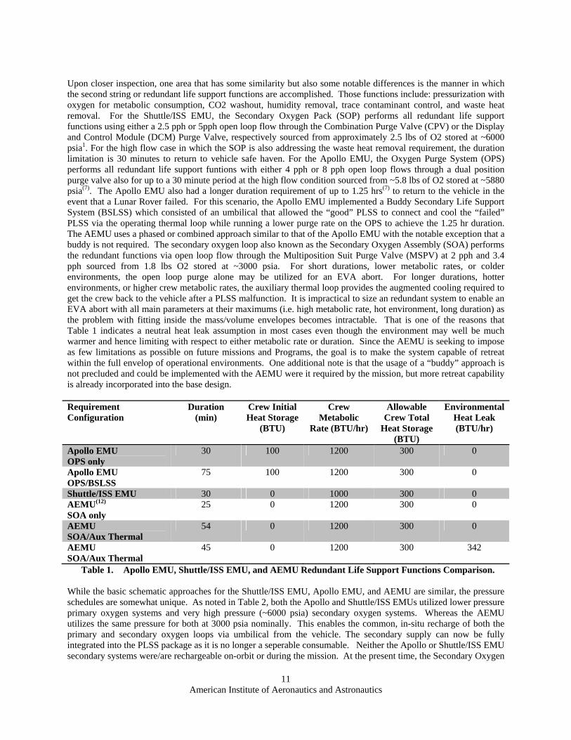
Upon closer inspection, one area that has some similarity but also some notable differences is the manner in which the second string or redundant life support functions are accomplished. Those functions include: pressurization with oxygen for metabolic consumption, CO2 washout, humidity removal, trace contaminant control, and waste heat removal. For the Shuttle/ISS EMU, the Secondary Oxygen Pack (SOP) performs all redundant life support functions using either a 2.5 pph or 5pph open loop flow through the Combination Purge Valve (CPV) or the Display and Control Module (DCM) Purge Valve, respectively sourced from approximately 2.5 lbs of O2 stored at ~6000 psia1. For the high flow case in which the SOP is also addressing the waste heat removal requirement, the duration limitation is 30 minutes to return to vehicle safe haven. For the Apollo EMU, the Oxygen Purge System (OPS) performs all redundant life support funtions with either 4 pph or 8 pph open loop flows through a dual position purge valve also for up to a 30 minute period at the high flow condition sourced from ~5.8 lbs of O2 stored at ~5880 psia(7). The Apollo EMU also had a longer duration requirement of up to 1.25 hrs(7) to return to the vehicle in the event that a Lunar Rover failed. For this scenario, the Apollo EMU implemented a Buddy Secondary Life Support System (BSLSS) which consisted of an umbilical that allowed the “good” PLSS to connect and cool the “failed” PLSS via the operating thermal loop while running a lower purge rate on the OPS to achieve the 1.25 hr duration. The AEMU uses a phased or combined approach similar to that of the Apollo EMU with the notable exception that a buddy is not required. The secondary oxygen loop also known as the Secondary Oxygen Assembly (SOA) performs the redundant functions via open loop flow through the Multiposition Suit Purge Valve (MSPV) at 2 pph and 3.4 pph sourced from 1.8 lbs O2 stored at ~3000 psia. For short durations, lower metabolic rates, or colder environments, the open loop purge alone may be utilized for an EVA abort. For longer durations, hotter environments, or higher crew metabolic rates, the auxiliary thermal loop provides the augmented cooling required to get the crew back to the vehicle after a PLSS malfunction. It is impractical to size an redundant system to enable an EVA abort with all main parameters at their maximums (i.e. high metabolic rate, hot environment, long duration) as the problem with fitting inside the mass/volume envelopes becomes intractable. That is one of the reasons that Table 1 indicates a neutral heat leak assumption in most cases even though the environment may well be much warmer and hence limiting with respect to either metabolic rate or duration. Since the AEMU is seeking to impose as few limitations as possible on future missions and Programs, the goal is to make the system capable of retreat within the full envelop of operational environments. One additional note is that the usage of a “buddy” approach is not precluded and could be implemented with the AEMU were it required by the mission, but more retreat capability is already incorporated into the base design. Requirement Configuration
Duration (min)
Crew Initial Heat Storage
(BTU)
Crew Metabolic
Rate (BTU/hr)
Allowable Crew Total
Heat Storage (BTU)
Environmental Heat Leak (BTU/hr)
Apollo EMU OPS only
30 100 1200 300 0
Apollo EMU OPS/BSLSS
75 100 1200 300 0
Shuttle/ISS EMU 30 0 1000 300 0 AEMU(12) SOA only
25 0 1200 300 0
AEMU SOA/Aux Thermal
54 0 1200 300 0
AEMU SOA/Aux Thermal
45 0 1200 300 342
Table 1. Apollo EMU, Shuttle/ISS EMU, and AEMU Redundant Life Support Functions Comparison. While the basic schematic approaches for the Shuttle/ISS EMU, Apollo EMU, and AEMU are similar, the pressure schedules are somewhat unique. As noted in Table 2, both the Apollo and Shuttle/ISS EMUs utilized lower pressure primary oxygen systems and very high pressure (~6000 psia) secondary oxygen systems. Whereas the AEMU utilizes the same pressure for both at 3000 psia nominally. This enables the common, in-situ recharge of both the primary and secondary oxygen loops via umbilical from the vehicle. The secondary supply can now be fully integrated into the PLSS package as it is no longer a seperable consumable. Neither the Apollo or Shuttle/ISS EMU secondary systems were/are rechargeable on-orbit or during the mission. At the present time, the Secondary Oxygen

American Institute of Aeronautics and Astronautics
12
Pack (SOP) is not rechargeable while on-board ISS and is treated as a consumable monitoring pressure decay and tracking each on-orbit checkout/activation. Loop Apollo EMU Shuttle/ISS
EMU AEMU
Primary Oxygen Pressure (psia) 1410 950 3000 Secondary Oxygen (psia) 5880 6000 3000 Primary Oxygen Regulated Pressure (suit pressure) psid 3.85 4.3 4.1-8.4 Secondary Oxygen Regulated Pressure (suit pressure) psid 3.85 3.7 3.7 Thermal Loop (psia) 3.853 15.5 3.0-23.54 Feedwater Loop (psia) 3.85 15.5/35 3.0-23.5
Table 2. Apollo EMU, Shuttle/ISS EMU, and AEMU Pressure Schedules. If the volume of the secondary oxygen supply can be tolerated at the lower storage pressure, which is the case presently for the AEMU, a lower storage pressure of 3000 psia possesses several advantages over the 6000 psia storage pressure:
Multiple compressor systems, including some previously certified for ISS, such as the Oxygen Recharge Compresor Assembly (ORCA) are capable of recharging a 3000 psia oxygen system. This includes the Cobham 3-stage rotary piston compressor being developed and certified as part of the Cabin Air Seperator for EVA Oxygen (CASEO). It is true that systems have been developed in the past that can charge oxygen supplies at pressures as high as 6000 psia using high pressure water electrolysis, cryogenic heating, etc but these systems represent a significant development and certification risk for the vehicle side of the recharge interface.
The likelihood of ignition in pure oxygen systems at elevated pressures such as 6000 psia are increased over that at 3000 psia with a number of mechanisms from pressure (elevated pressure descreases the ignition temperature and increases the burn-rate of many materials(13)), particle impact, adiabatic compression heating, flow friction heating, and kindling chain all becoming more heightened at the elevated pressure. This is not to say that a 3000 psia oxygen system is non-hazardous, but potentially lesser so than a 6000 psia system.
Issues such as Joule-Thompson expansion cooling become more significant at higher pressure drops which poses several potential issues. As noted back with the Apollo EMU OPS, a 116W heater(7) was initially added to the system to mitigate the risk of having the gas expanding through the regulator drop to the frost point of the supply gas. This was later removed after a test program. For the Shuttle/ISS EMU, the Joule-Thompson cooling posed a different problem for a regulator system that sees significant ground testing like the SOP regulator. During the SOP Contamination failure investigation that occurred in 2000(14), one of the contamination mechanisms for collecting hydrocarbon oil in the regulator seat area was theorized to be vapor condensation from the -60F temperatures achieved during expansion across the seat when fed with oxygen per SE-S-0073 which allowed for 55ppm total hydrocarbons counted as methane. Under this scenario, the several hundred pounds of nitrogen and then oxygen flowed through the regulator during acceptance testing yielded a risk of contamination. As a method of correction, liquid nitrogen cold traps were installed in front of the SOP regulator during ground processing; this would be another burden that a vehicle system might need to consider if attempting to provide a 6000 psi gas supply.
As can be noted in Table 2, the operating pressures are similar across all systems discussed here with the notable distinction that the AEMU is adjustable to higher pressures that facilitate zero prebreathe protocols, Decompression Sickness (DCS) treatment, or vehicle docking for suitport configured vehicles.
3 Apollo EMU used a check valve to allow pressurization and makeup of water from the feedwater loop into the thermal loop 4 AEMU combines the thermal and feedwater loops together. 5 Shuttle EMU uses a pressure regulator to drop the supply pressure from the main feedwater loop to the sublimator with a check valve/solenoid valve assembly that allows makeup water into the thermal loop from the feedwater loop.
American Institute of Aeronautics and Astronautics
13
The feedwater and thermal loops vary across the systems, largely driven by the style of pump used in the thermal loop and other factors that will be discussed later. For the Apollo EMU, the suit pressure was utilized to pressurize the feedwater and thermal loops. For the Shuttle/ISS EMU, a separate regulator (Item 113E) was used to divert part of the primary oxygen supply to preussize the feedwater tanks to ~ 15.5 psid with a subsequent regulator in front of the sublimator that regulates the inlet supply pressure to ~3 psia. For the AEMU, like the Apollo EMU, the suit pressure is used to pressurize the feedwater bladders that feed the thermal loop such that it runs at a pressure slightly lower than suit pressure based on the compliance of the bladder.
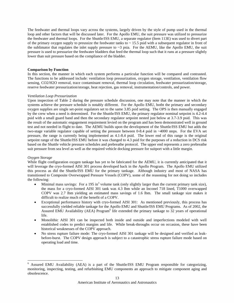
Comparison by Function In this section, the manner in which each system performs a particular function will be compared and contrasted. The functions to be addressed include: ventilation loop pressurization, oxygen storage, ventilation, ventilation flow sensing, CO2/H2O removal, trace contaminant removal, thermal loop circulation, feedwater pressurization/storage, reserve feedwater pressurization/storage, heat rejection, gas removal, instrumentation/controls, and power. Ventilation Loop Pressurization Upon inspection of Table 2 during the pressure schedule discussion, one may note that the manner in which the systems achieve the pressure schedule is notably different. For the Apollo EMU, botht the primary and secondary oxygen supplies are single set-point regulators set to the same 3.85 psid setting. The OPS is then manually engaged by the crew when a need is determined. For the Shuttle/ISS EMU, the primary regulator nominal setpoint is 4.2-4.4 psid with a small guard band and then the secondary regulator setpoint nested just below at 3.7-3.9 psid. This was the result of the automatic engagement requirement levied on the program and has been demonstrated well in ground test and not needed in flight to date. The AEMU builds upon the development of the Shuttle/ISS EMU but adds the two-stage variable regulator capable of setting the pressure between 0-8.4 psid in ~4000 steps. For the EVA set pressure, the range is currently being implemented as 4.1-8.4 psid. The lower end of this range is the original setpoint range of the Shuttle/ISS EMU before it was changed to 4.3 psid for the purposes of a reduction in DCS risk based on the Shuttle vehicle pressure schedules and prebreathe protocol. The upper end represents a zero prebreathe suit pressure from sea level as well as the required vehicle docking pressure for suitport with a little margin. Oxygen Storage While flight configuration oxygen tankage has yet to be fabricated for the AEMU, it is currently anticipated that it will leverage the cryo-formed AISI 301 process developed back in the Apollo Program. The Apollo EMU utilized this process as did the Shuttle/ISS EMU for the primary tankage. Although industry and most of NASA has transitioned to Composite Overwrapped Pressure Vessels (COPV), some of the reasoning for not doing so includes the following:
Minimal mass savings: For a 195 in3 volume tank (only slightly larger than the current primary tank size), the mass for a cryo-formed AISI 301 tank was 4.3 lbm while an Inconel 718 lined, T1000 overwapped COPV was 2.7 lbm yielding an estimated mass savings of 1.6 lbm. The small tankage size makes it difficult to realize much of the benefit of a COPV.
Exceptional performance history with cryo-formed AISI 301: As mentioned previously, this process has successfully yielded reliable tankage for the Apollo EMU and Shuttle/ISS EMU Programs. As of 2002, the Assured EMU Availability (AEA) Program6 life extended the primary tankage to 32 years of operational life.
Monolithic AISI 301 can be inspected both inside and outside and imperfections modeled with well established codes to predict margins and life. While break-throughs occur on occasion, these have been historical weaknesses of the COPV approach.
No stress rupture failure mode: The cryo-formed AISI 301 tankage will be designed and verified as leak-before-burst. The COPV design approach is subject to a catastrophic stress rupture failure mode based on operating load and time.
6 Assured EMU Availability (AEA) is a part of the Shuttle/ISS EMU Program responsible for categorizing, monitoring, inspecting, testing, and refurbishing EMU components an approach to mitigate component aging and obsolescence.

American Institute of Aeronautics and Astronautics
14
Ventilation A cursory review of the Apollo EMU in comparison to the AEMU would see a great deal of similarity, both with Brushless DC (BLDC) motor powered centrifugal fans. However, they diverge from there. The Shuttle/ISS EMU also utilized a BLDC motor power centrifugal fan, but also coupled with it, a water pump and rotary pitot water separator such that it became known as the Fan/Pump/Seperator (F/P/S). The reasoning for this was a 10W(3) savings over the separated Apollo EMU fan and pump, however this had far reaching effects for the system during implementation. Since the F/P/S all ran from the same BLDC motor and no gearing was utilized to ratio the rotary speed, all devices ran at the single setpoint speed of ~19.7 krpm. The implications for the pump and feedwater loop were significant and will be discussed in the thermal loop circulation section below. Due to issues early in implementation with moisture damage to the hall effect sensors utilized to sense armature position and commutate the BLDC motor, the stator and drive electronics were isolated from the wetted loop and armature via a “can” that was added to the motor. This has the added benefit of providing isolation of those same electronics from the 100% oxygen utilized in the ventilation loop which has become the main reason for keeping it once the ventilation loop moisture risk has been lowered. For the AEMU, the water separator function has been addressed by a separate component, allowing for the separation of the pump and fan more like that of the Apollo EMU. Advances in fan design and motor/electronics have allowed the separated fan and pump to save another ~10W over that of the Shuttle/ISS EMU fan. Much of that improvement can by attributed to the change from a metallic can within the fan motor to a ceramic can resulting in reduced electromagnetic field losses between the stator and armature and hence, greater efficiency between electrical input power and mechanical shaft output power. The additional capability that the AEMU fan will include is the ability to run at a constant volumetric flowrate across a range of conditions. This is accomplished by running a closed loop speed control circuit with local motor speed via hall effect sensors but the volumetric flowrate feedback coming from the vent flow sensor. Hence, the motor speed will be adjusted to achieve the desired volumetric flowrate across a variety of suit configurations and operating conditions. Later in development, if this added complexity (or capability depending on how it is viewed) is no longer required, it can be reduced to a static speed control approach like the Shuttle/ISS EMU fan but with Pulse Width Modulated (PWM) control of motor current. As for the volumetric flow rate range, the AEMU will continue to use the ~6 acfm range used for Apollo EMU and Shuttle/ISS EMU, until the suit configurations, analysis, and test permit a lower flowrate…but is easily controlled across a range from 4-7 acfm at present. Ventilation Flow Sensing As part of the Apollo EMU, vent flow sensing was an analog output using a capacitive based Differential Pressure (DP) sensor across a low DP venturi design(7). The capacitive DP sensor was sensitive to moisture and required special handling such as vacuum dryouts. For the Shuttle/ISS EMU, the vent flow sensor was transitioned from an analog device to a discrete device utilizing a flapper tied to a microswitch that was set to trigger or close under spring load at flow rates lower than ~3.7 acfm(3). With allowance for a slightly higher DP (~.65 vs .32 in-H2O), the AEMU is currently implementing an analog output flow sensor that takes advantage of technologies not available to the earlier programs. The sensor uses the V-coneTM flow sensor with the measured by a media-isolated, MEMS-based differential pressure sensor. The V-coneTM offers low permanent pressure loss while the DP sensor reduces moisture sensitivity providing stainless steel diaphragms as the only wetted materials less the elastomeric o-seals that seal the cavity. CO2/H2O Removal For the Apollo EMU and early Shuttle/ISS EMU, lithium hydroxide (LiOH) was the primary means of removing CO2. The canisters were single use items that worked well for missions with few EVAs as was required for the Apollo and Shuttle Programs. For the ISS Program, the Shuttle/ISS EMU switched its preferred CO2 scrubbing method to silver oxide also known as Metox; a canister that could be regerated in a specially designed “oven” in the ISS Eqiupment Lock. The switch to Metox lowered the consumable hit from an ISS mission perspective, but it still represented a single scrubbing bed that had a finite EVA scrubbing capacity of ~1.6 lbs CO2, which was somewhat less than the EVA community had gotten accustomed to with the LiOH canisters (typically ~2 lbs CO2 at 85% conversion). For H2O removal, the Apollo EMU utilized a condensing heat exchanger (HX) and static elbow separator with a wick that fed captured water back to a retention tank that was drained post-EVA. The Shuttle/ISS EMU upgraded this approach, while still utilizing a condensing HX, it added slurper holes in the HX which fed to the inlet of a rotary drum pitot separator that was part of the F/P/S. There, the water was separated and pumped back to the feedwater tanks for used in the Sublimator and the gas was returned to the ventilation loop at the fan. This improvement removed the need to separately dump the condensate post-EVA and also made the condensatue available for use during the EVA, however for long term missions like ISS, it turned out to have detrimental effects

American Institute of Aeronautics and Astronautics
15
on microbial control as the condensate which was loaded with microbes from the ventilation loop was then mixed into the feedwater tanks. The AEMU differs greatly from its predecessors in this area as it utilizes technologies that were not available to these earlier Programs. Instead of a single scrubber bed, the AEMU implements a dual bed system utilizing the SA9T amine from Hamilton Sundstrand referred to as the Rapid Cycle Amine (RCA) swingbed which adsorbs CO2/H2O when exposed to the ventilation loop and then desorbs those same CO2/H2O molecules when exposed to vacuum. This technology is common with the CO2 And Moisture Removal Amine Swingbed (CAMRAS) system that has been in development with the ECLSS community for use on vehicles like Orion. The benefit of the RCA is that for a minor impact to the power and oxygen consumables, the CO2 scrubbing bed is no longer a consumable as it continuously regenerates during the EVA swinging between beds A or B as they saturate. The other benefit is that with the H2O removal handled by the RCA, there is no longer a need for a condensing HX, water separator, or condensate storage. For the AEMU, this allowed for a complete separation of the ventilation loop from the thermal loop which reduce the microbial load seen in the thermal loop and feedwater tanks over the longer duration missions. Trace Contaminant Removal Activated charcoal has been used for trace contaminant removal since the Apollo EMU with little change. The Shuttle/ISS EMU has integrated activated charcoal into the Metox canister which is regenerated post-EVA making it a reusable quantity. For the AEMU, most of the driving requirements are the same with the exception that the NH3 generation rate is elevated due to the amine present in the RCA. However, the ullage loss from the RCA To that end, the AEMU is presently pursuing the use of activated charcoal impregnated with compounds such as ZnCl2 or H3PO4 to provide the trace contaminant removal(15). Thermal Loop Circulation The Apollo EMU utilized a diaphragm style positive displacement pump that allowed for thermal loop operating pressures down at suit pressure levels without cavitation. The pump provided 240pph with a head rise of 5.65 psi and power consumption of 10W(7). For the Shuttle/ISS EMU, when the pump was combined as part of the F/P/S and forced to run at a shaft speed of ~19.7 krpm, the centrigufal pump design was incapable of running at the lower suit pressure driven thermal loop pressures resulting in the addition of an additional gas-side regulator (Item 113E) as well as relief valves (Item 120) to pressurize the feedwater bladders to ~15.5 psid(3). Courtesy of the RCA removal of H2O vapor from the ventilation loop, the fan and pumps were separated for the AEMU, allowing the pump to be optimized for the desired operational pressure ranges and flowrates. As a result, the AEMU is utilizing a gerotor or “generated rotor” positive displacement pump capable of providing > 10 psid head rise at 200 pph while consuming less than 10W (not counting BLDC motor controller losses). Thus far the gerotor has operated at pressures below ~3 psia without cavitation allowing the AEMU to utilize feedwater bladders pressurized by suit ventilation loop pressure. Feedwater Pressurization Feedwater and thermal loop pressurization under the Apollo EMU was accomplished by suit/ventilation loop pressure on a compliant bladder. The Shuttle/ISS EMU performed a similar approach but utilized a separate and higher pressure gas supply as discussed previously. For this application, the feedwater tanks were housed within the aluminum watertank structure which makes the basis for the PLSS shape. The primary bladders were separated due to volumetric constraints into two separate bladders referred to as the Large and Small Main bladders and tied together with small tubing runs through/around the watertank structure. These bladders cannot be visually inspected by the crew as they require invasive maintenance activities performed during ground processing. Hence, there is no direct manner in which to note excessive contamination (from microbial or other) or to observe the presence of large gas bubbles. The team supporting the Shuttle/ISS EMU has managed to maximize their telemetry to detect the presence of bubbles during operational transitions such as the depress to 10.2 psi that occurs during a campout operation on ISS; using the Ideal Gas law, the differential pressures across the feedwater bladders is monitored allowing for a back-calculation on possible gas bubble size if the pressures do not trend nominally. The integration PLSS to SSA integration of the AEMU is in its infancy at this point, but the current plan includes the use of a variable compliance transparent feedwater bladder that will be mounted in the back hatch area behind the crew inside the SSA. This reduces the suit penetration count and utilizes relatively dead space in the SSA to allow the PLSS volume to reduce while providing for as much as 10 lbs of available feedwater. Two different bladder options are presently being developed, both of which offer the ability to directly inspection the bladder, as well as its contents for contamination, excessive gas bubbles, etc. It is also intended to be a mission replaceable item so that a fouled or damaged feedwater bladder may be remedied. In the end, the visual inspection preEVA may prove

American Institute of Aeronautics and Astronautics
16
cumbersome or impractical as the integration matures but the ability to inspect and repair during the mission is expected to remain and prove useful for long duration missions. Reserve Feedwater For the Apollo EMU, the reserve bladder was added as a necessity to augment the primary bladder water volume in support of an 8 hr EVA requirement on the -7 PLSS(5) that supported Apollo 15-17. For the Shuttle/ISS EMU, a reserve tank was added as a reliable way to determine when the feedwater quantity was running low so that risk of using the SOP in open loop purge would be mitigated. The tank is separated from the main bladder flow passage via a relief valve that cracks and flows at ~ 4 psid(3); this is then detected by an empirically determined differential pressure of 2.1 psid between the gas and water side pressure transducers. For the AEMU, the PLSS is being designed to support an 8 hr EVA from the outset and the water quantity determination is planned to operate a bit differently. The AEMU will include a single variable compliance bladder that alters its pressure output as a function of available water quantity. The primary method for water quantity determination will be via a utilization calculation from the Spacesuit Water Membrane Evaporator (SWME). With malfunction of that computation or external feedwater leakage, the AEMU will utilize an empirically determined pump inlet pressure to detect a low bladder condition, much like was accomplished with the relief valve on the Shuttle/ISS EMU but without moving parts. Heat Rejection As with the RCA in the ventilation loop, one of the most significant technological improvements for the AEMU over its predecessors is in the area of heat rejection via the Spacesuit Water Membrane Evaporator (SWME). Both the Apollo EMU and Shuttle/ISS EMU utilize sublimators which are sensitive to contamination, applied pressure, applied heat flux (at start-up), and ambient pressure (especially above the triple point of water). For the SWME, thousands of hydrophobic hollow-fibers are utilized to directly evaporate the thermal loop water through the membrane wall with the overall heat flux controlled by a linear actuator controlled poppet valve which varies the back-pressure. With the bulk of the contaminants remaining in the thermal loop and only water vapor crossing the membrane wall, the SWME is able to continually tolerate contaminated water(16) that would quickly clog a sublimator. In contrast to the sublimator which has a narrow permissible pressure range, especially at start-up, in order to avoid break-through, the SWME performance is pressure independent within the range of suit operating pressures and has been demonstrated to perform nominally with pressures as high as 27.7 psid(16); this provides freedom to integrate the SWME into the loop in the simplest manner possible with inlet pressure no longer a driving requirement. The SWME has a way to go in order to achieve the maturity of design that sublimator implementations possess, but one of the key issues that has plagued the sublimators on the Shuttle/ISS EMU Program has also been eliminated via the SWME; that issue is the sensitivity of the gap below the porous plate and the risk of damage to that gap via plate warpage from an inadvertent feedwater switch throw. Another side benefit of the SWME which has a significant impact on the system schematic is its ability to degas the thermal loop water flowing through it. This will be discussed in a subsequent section. Thermal Loop Gas Removal The gas removal methods between the Apollo EMU, Shuttle/ISS EMU, and the AEMU diverge significantly. For the Apollo EMU, a static 400mesh(6,7) separator was used but could only handle 37 cc of gas volume before breaking through. A vent valve was then used in conjunction with the local g-field to remove the gas. This option was not available for the Shuttle/ISS EMU given its LEO operational regime. The gas removal was implemented as a 20 micron absolute pleated filter screen shaped in a cylinder with a probe down the center axis which fed the gas bubble/water mixture to the F/P/S(3). This provided for continuous gas removal capability in a micro-gravity environment. For the AEMU, the degassing function is accomplished via the SWME. The SWME hollow fiber membranes are hydrophobic but readily pass intrained gas through the walls and out regardless of g-field and ambient pressure. Instrumentation/Controls Another area that has changed significantly over the decades since the Apollo EMU and into the current Shuttle/ISS EMU to the plans for the AEMU is the on-board avionics and instruments used to assess the health and control the system. For the Apollo EMU, there was minimal telemetry and interaction with the crew in the manner of alarming or monitoring; a total of 10 analog channels were telemetered to the ground and a total of five malfunction lights were displayed to the crew(5):
1. Low feedwater pressure

American Institute of Aeronautics and Astronautics
17
2. Low PGA pressure 3. Low vent flow 4. High O2 flow 5. PPCO2 was present but not connected by -7 PLSS at the end of the Program
For the Shuttle/ISS EMU, on-board diagnostics, alarming, and telemetry capabilities were evolved with the Program requirements to the present state on ISS which utilizes the Enhanced Caution and Warning System (ECWS) powered by a UTRC196 16-bit processor. The system monitors 16 analog channels, ~12 discrete channels, computes consumables and determines the limiting consumable and associated EVA time remaining, traps faults with limits tied to elaborate logic controlling state transitions between 8 differnent states, provides the crew with warning messages and prompts for action, and telemeters the data to the vehicle (and eventually to the ground). The ECWS has much more capability than can be described in a simple run-on sentence, but point is that is a dramatic increase in on-board suit computational power and autonomy over the Apollo EMU. The avionics designs for the AEMU are in their infancy, but the AEMU takes another step towards the “fly by wire” approach by having the regulators, Thermal Control Valve (TCV), RCA, SWME, fan, and pump all driven by stepper actuators or BLDC motors controlled by local controllers with a differential signaling link to a Caution Warning and Control System (CWCS) which not only monitors the system like ECWS from the Shuttle/ISS EMU, but also controls the system. Advances in instrumentation, largely due to MEMS technologies of the last decade or so, have allowed instrumentation to be low power, small, and yet offer improved accuracies, sensitivities, etc. The AEMU includes, at present, a significantly higher instrumentat count than that of the Shuttle/ISS EMU. Through the use of the Failure Modes and Effects Analysis (FMEA), redundant instrumentation that does not buy-down risk is being removed and other instrumentation is being added. In the end, the computing power and capabilities for automated checkout and remote diagnosis of the AEMU will exceed that offered by the current Shuttle/ISS EMU as it must for long, remote missions planned for the future. Power The Apollo EMU utilized by the -7 PLSS, a non-rechargeable 360 W-hr Ag-Zn battery. For the Shuttle/ISS EMU, a few battery configurations have been used including rechargeable Ag-Zn batteries of varying sizes from ~450 W-hr to ~540 W-hr in nominal capacity. The Shuttle/ISS EMU is presently using a Li-Ion based battery called the Long Life Battery (LLB) of the same basic W-hr capacity but with a much longer wet life and higher cycle life. The AEMU does not yet have a battery design as the power requirements are in-flux from the evolution of the PLSS powered PLSS components, although one goal is to lower the power consumption such that a current Shuttle/ISS EMU battery design could be utilized.
IV. Summary and Conclusions The AEMU with comparisons back to the Shuttle/ISS EMU and Apollo EMU has clearely evolved from these systems with differences driven by new technologies, failure corrective actions, lessons learned, and requirements changes. Given that the AEMU seeks to be a more general suit design capable of exploring LEO, the moon, Mars, and beyond without exclusionary choices that suit a single destination, it is reasonable to observe the evolution of the design from two successful designs that have explored and operated in micro-gravity (Shuttle/IS EMU) and on the lunar surface (Apollo EMU). In reviewing history, each generation of engineers believes they have the remedy for the problems of the previous generation via a new solution and each generation realizes that each new solution poses its own problems to solve. The AEMU will be no different as its “features” will not be fully realized until it is fabricated, tested, and used. Both the Apollo and Shuttle/ISS EMU Programs have been very successful in achieving the mission goals and over-coming or mitigating these “features” as the hardware has matured. The AEMU will need the same dedication, innovation, and effort with the hope of achieving the same level of success.
V. Path Forward The path forward for the AEMU PLSS consists of a number of iterations and a lot of failures. The first bread-board level AEMU PLSS refered to as PLSS 1.0 was built and tested in 2011 with many failures and lessons learned. For that design, the schematic was assembled with 5 key components:
Primary Oxygen Regulator (POR) Secondary Oxygen Regulator (SOR) Rapid Cycle Amine (RCA) Ventilation Fan

American Institute of Aeronautics and Astronautics
18
Spacesuit Water Membrane Evaporator (SWME) The remainder of the functions were implemented with COTS or modified COTS hardware on an item bar rack that was ~1200 lbs. For 2012, the first packaged PLSS (referred to as PLSS 2.0) since the early Shuttle/ISS EMU will be fabricated and tested in 2013. This will be an unmanned, nitrogen only PLSS with all active components of custom design but will COTS fluids connections and a number of other compromises. From there, the first fully configured prototype (referred to as PLSS 2.5) will be fabricated; this will be unmanned, nitrogen only and without the associated paper that accompanies an oxygen-rated, human-rated system but physically the same in all respects. With successful assembly and testing of that unit, the first oxygen-rated, human-rated PLSS (referred to as PLSS 3.0) will be constructed. To those who might ask why the iterations, it takes only a quick look at history to see the answer. The Apollo EMU, by the end of the Program, and having a great deal more resources than are being allocated to this PLSS development, still went through 8 configurations to address changing requirements and “features.” To quote a wise man who spent much time shaping the Shuttle/ISS EMU…”if you don’t designate a development unit, you’ll still have one, it will just be your certification unit…” (Joe McMann, personal words).
References 1NASA Extravehicular Mobility Unit (EMU) LSS/SSA Data Book, Rev M, Hamilton Sundstrand, NASA, 2008. 2Campbell, C., Technology Development Specification for the Primary Oxygen Regulator (POR), Rev B, NASA, June 2009. 3Extravehicular Mobility Unit (EMU) Requirements Evolution, Rev B,, SEMU-66-017 Hamilton Sundstrand, NASA, Sept
2005. 4Oxygen Compatibility Assessment Report for the Extravehicular Mobility Unit (EMU) Secondary Oxygen Pack,
OXHAZ/FAIL.0224, NASA, Oct 2006. 5Goodwin, Fred H.,Apollo PLSS – A Criterion for Space Back Pack Equipment, AIAA Crew Equipment Systems
Conference, AIAA-73-1329, Las Vegas, NV., Nov-1973. 6CSM/LM Spacecraft Operational Data Book, Volume IV, EMU Data Book, Rev 2, SNA-8-D-027, July-1971. 7Lutz, C., Stutesman, H., Carson, M., McBarron II, J., Apollo Experience Report-Development of the Extravehicular Mobility
Unit, NASA TN 0-8093, Nov-1975. 8Operations Concept Document, EVA Systems Project Office, CxP 72177, Rev B, Jun-2008. 9Schematics and Behavioral Description of the AEMU Portable Life Support System (PLSS), CTSD-ADV-959, Rev N/C,
Apr-2012. 10 McMann, J., McBarron II, J., Challenges in the Development of the Shuttle Extravehicular Mobility Unit (EMU), N85-
16922, 1985. 11 Constellation Space Suit Element, PLSS Schematic Selection Study, JSC-65443, Feb-2007. 12Navarro, M., Conger, B., Campbell, C., Exploration Extravehiculator Activity Purge Flow Assessment, AIAA-2011-5220,
International Conference on Environmental Systems (ICES), Portland, OR., July-2011. 13Standard Guide for Designing Systems for Oxygen Service, ASTM G88-05, 2005. 14EMU Reliability Data Report:Oil Contamination in EMU High Pressure Oxygen System, H-EMU-000--001, 2001. 15Paul, H., Jennings, M., Waguespack, G., Requirements and Sizing Investigation for Constellation Space Suit Portable Life Support System Trace Contaminant Control, AIAA-2010-6065, International Conference on Environmental Systems (ICES), Savanna, GA., July-2010.
16Bue, G., Makinen, J., Vogel, M. et.al., Hollow Fiber Flight Prototype Spacesuit Water Membrane Evaporator Design and Testing, AIAA-2010-6065, International Conference on Environmental Systems (ICES), Portland, OR., July-2011.