Advanced Electronics 1
158
Training Documentation for Maserati Service Network Advanced Electronics 1 Engine and Power Train March 2008 Edition
Transcript of Advanced Electronics 1

Training Documentation for Maserati Service Network
Advanced Electronics 1 Engine and Power Train
March 2008 Edition

Maserati Academy
Advanced Electronics 1
2
Advanced Electronics part 1Engine and Power Train
• Engine control system (Bosch Motronic)
• Robotized gearbox control system (Marelli)
• Automatic gearbox control system (ZF-Bosch)
Contents

Maserati Academy
Advanced Electronics 1
3
Engine Control SystemBosch Motronic
Engine Control System

Maserati Academy
Advanced Electronics 1
4
Engine Control System (Bosch Motronic)
INTRODUCTION
The management of modern engine control systems must take account of the searchfor maximum performance while associating this with maintenance of optimal handlingand environmental respect.
Certain types of engine performance are possible only through the integration ofelectronic systems that acquire and process operating parameters, and this must beachieved in real-time, i.e. as fast as possible. Likewise, activations must beimplemented almost instantaneously.
This document gathers together diagnostic elements concerning components of the control systems implemented on our cars in order to provide useful information forrapid and effective troubleshooting, reducing intervention times on the vehicle.
The engine control systems used on the most recent Maserati models are as follows:
• 3200 GT (M338): Marelli IAW 4CM• Coupé, Spyder, Gransport (M138): Bosch Motronic ME 7.1.1• Trofeo (M138): Bosch Motronic ME 7.1.1• Trofeo Light (M138): Italtecnica, dedicated to Motorsport• Quattroporte (M139): Bosch Motronic ME 7.1.1• GranTurismo (M145): Bosch Motronic ME 7.1.1• MC12 road version (M144): 2 x Bosch Motronic ME 7.1.1• MC12 race version: 2 x Bosch Motronic ME 7.1.1,
(without air flow sensors)• MC12 GT1: Marelli, dedicated to Motorsport
This manual describes exclusively the Bosch Motronic ME 7.1.1 system
Engine Control System

Maserati Academy
Advanced Electronics 1
5
Engine control unit Throttle bodyAccelerator pedal
Sensors Actuators
THE TORQUE BASED MODEL:
The main objective of the engine control system is that of delivering engine torque("Torque based" model). This strategy is applicable in all conditions of engineoperation. We can identify three different torque request levels: driver torque request, external torque request, and internal torque request. When the engine is idling the target is a constant rpm value. This rpm target is subsequently transformed by the ECU into a torque target.
TORQUE DEMAND MANAGEMENT
MODULE
Coordination betweentorque demands
and Efficiency
requirements
DRIVER TORQUE REQUESTAccelerator pedalCruise Control
INTERNAL TORQUE REQUESTStartingIdling ControlEngine Speed LimiterEngine Protection
EXTERNAL TORQUE REQUESTESP, ASR, Traction ControlHandling
TORQUE CONVERSION
MODULE ..
Generationof desired torque
.
.
Calculated
Fuel Cut-off
Ignition Timing.
Throttle Angle
target torque
torque
Engine Control System

Maserati Academy
Advanced Electronics 1
6
Injector
Throttle
Sparkplug
Air flow meter
Accelerator
pedal
AirMain path
Spark
Fuel
wped_w [% PED]0.0000
12.440725.6794
44.2603
62.8397
85.0004100.0000
nmot_w [U/min]6000.000
4000.0002500.000 1520.000 700.000
0.0000
100.0000
[%]
Accelerator pedal
position
engine rpm
Rel
ativ
e en
gine
torq
ue[%
]
TORQUE REQUEST: PEDAL MAP
MOTRONIC PRIMARY FUNCTIONAL STRUCTURE:
Engine Control System

Maserati Academy
Advanced Electronics 1
7
When the vehicle is cruising at minimum throttle sufficient torque must be delivered toovercome friction forces: C0
The same C0 can be delivered with less advance but more throttle: the situation is asthough C1+C2=C0 then C2-C0=C0-C1 and is defined as torque reserve
This makes it possible to exploit:
• The concept of a transient refers to the transition between two stable situations.
• There are two types of transients: acceleration and deceleration.
• In acceleration it must be taken into account that part of the fuel will bedeposited on the walls as a fluid film. It is therefore necessary to inject more fuelthan theoretically calculated.
• Vice versa, in deceleration the previously deposited film will detach from the walland enter the combustion chamber. Therefore less fuel must be injected thantheoretically calculated.
TORQUE RESERVE STRATEGY:
• fast C0-C1 torque delivery (even though of modest entity) for breakawayacceleration
• hot exhaust gas to heat the catalytic converter (the advance is retarded in C1)• the negative aspect is that combustion is impaired (non-optimal spark advance)
TRANSITION STRATEGY:
Engine Control System

Maserati Academy
Advanced Electronics 1
8
• When the accelerator pedal is pressed the engine speed should increaseuniformly.
• If the effective speed increase curve deviates from the theoretical curve the effect is described as "flutter".
• Torque flutter is experienced as longitudinal oscillation of the car.
• The causes of this phenomena include incorrect torque filters, play (transmission, engine), lean engine, etc. To eliminate flutter reduce sparkadvance in proportion to the deviation of engine speed.
• In A the engine is being driven (drag torque): negative torque at clutch.
• In B the accelerator pedal is pressed: first filter to bring the engine to the neutralposition.
• In C the transition of the engine from the neutral position to the torque delivery position is filtered.
DRIVEABILITY: TORQUE REVERSAL
DRIVEABILITY: "FLUTTER"
Engine Control System

Maserati Academy
Advanced Electronics 1
9
MAIN SYSTEMS
In order to run, the engine needs several basic parameters:1. Air2. Fuel3. Spark
The main engine systems are as follows:1. Aspiration system2. Fuel system3. Ignition system
In practical terms it is necessary to:1. Scavenge burnt gas by means of the exhaust system.2. Cool the engine by means of the coolant circuit.3. Lubricate the engine with oil and the relative oil lubrication circuit.4. …
Engine Control System

Maserati Academy
Advanced Electronics 1
10
Moreover, anti-pollution regulations prescribe that:
Fuel vapours that form in the fuel tank must be recycled to the fuel intake and the absence of leaks from the fuel tank must be guaranteed;
Oil vapours formed in the crankcase must be routed to the intake system;
Whenever necessary, use a "Secondary Air" system that delivers air into the exhaustsystem when it is still cold in order to complete the reaction of incombustibles and bringthe catalytic converter to a condition of full efficiency faster;
MAIN SYSTEMS
Engine Control System

Maserati Academy
Advanced Electronics 1
11
SYSTEM COMPONENTS
• Engine control unit• Air flow meter• Air temperature sensor• Coolant temperature sensors• Accelerator pedal• RPM sensor• Timing sensors• Timing variators with solenoid valves• Knock sensors• Oxygen Sensors (pre- and post-cat.)• Motor-driven throttle• Injectors
• Coils• Fuel pump• Anti-evaporation system• DMTL system• Secondary air system
Engine Control System

Maserati Academy
Advanced Electronics 1
12
Engine Control System
The two main 32-bit microprocessors are located internally in the Motronic ME 7.1.1 control unit. Engine control system diagnostics functions on three levels and isintegrated in the two microprocessors. Approximately 60% of the calculation capacityof the control unit is employed for the various diagnostic functions and emissionscontrol, while the remaining 40% is devoted to effective control of engine performance.
Drive-by-wireImmobilizerOnboard diagnosticsCatalytic converter warm-upSecondary Air SystemAutomatic transmissioncontrolTorque ControlAutomatic altitude correction
Detonation ControlOverpressure controlOnboard diagnosticsTimed injectionSelf-diagnosticsTiming ControlCanister Purge ControlLambda ControlCruise Control
StartingHeatingAccelerationShut-off during decelerationSelf-diagnosticsSophisticated ignition mapRPM limiter
Performance
Emissionreduction
Preservationstrategies
Safetystrategies
Diagnostics
Fuelconsumptionreduction
BOSCH MOTRONIC ENGINE CONTROL UNIT

Maserati Academy
Advanced Electronics 1
13
ENGINE CONTROL SYSTEM SOFTWARE VERSION
Example table, always check Modis for the latestrelease published!
Engine Control System
Checking of the engine node software combined with the transmission software is offundamental importance for correct diagnostics.
Before making any replacements or disassembling any parts of the car involvingproblems related to the engine or transmission control unit, it is mandatory to check the correspondence between the Engine SW and the Transmission SW, as shown in the table published on Modis, which is constantly updated by the Maserati TechnicalAssistance Service.
Also in the event of replacement of a control unit it is indispensable to subsequentlycheck correct matching as per the table, in accordance with the assembly N°, Model, Year, and hardware version of the node concerned.

Maserati Academy
Advanced Electronics 1
14
The Software is checked with SD3, interrogating the engine control node and the transmission control node and subsequently checking compatibility by means of the table and performing a remote download if necessary.
Engine Control System

Maserati Academy
Advanced Electronics 1
15
ENGINE CONTROL SYSTEM POWER SUPPLY+ Vbatt
Key On
The engine control system is supplied with 12V from the car battery. The Motronic ME 7.1.1 control unit is connected to ground (pin1 and pin2) and Vbatt (pin62). At the time of Key On, the control unit receives +12V (pin21) and consequently triggersthe main relay by means of an "active low" mode signal (pin23). The main relayprovides the main power supply to the control unit and to the various engine controldevices that require a 12V power input. This serves to activate the engine controlsystem. The presence of Vbatt (pin62) is used for the KAM memory (for example: throttle self-learning) and for activation of certain subsystems that are active in Key OFF conditions(e.g.: DMTL system).
Influence of battery voltage:Injection system: the speed of injector opening and closing depends on the batteryvoltage. The ECU corrects the injection time to compensate for voltage variations. Ignition system: when the battery voltage is low, the ECU extends the coil activationtime to ensure sufficient charging.
Engine Control System

Maserati Academy
Advanced Electronics 1
16
REGULATED POWER SUPPLY FOR SENSORS
Enginecontrol
unit Component
+ 12V
+ 5V regulated
Component ground
Various engine control system sensors use a regulated 5V power supply. This powersupply is regulated with respect to a specific reference ground for the components in question. This solution is necessary for two reasons:
• Operational accuracy: all voltage fluctuations are filtered out.
• Short-circuit protection: thanks to a specific ground circuit that iselectrically isolated from the vehicle ground.
During checking and diagnostics of components: always measurethe power supply voltage with respect to the component ground and not with respect to the vehicle ground!
Engine Control System
The Motronic ECU retains the error codes detected during the self-diagnostic routine in its internal Eprom memory. Even when the battery is disconnected the ECU retains the errors in the memory, which is of the "flash Eprom" type.

Maserati Academy
Advanced Electronics 1
17
BANKS NOMENCLATURE:
MC12: 2 x Bosch Motronic ME 7.1.1
ECU 1 (right-hand bank) = MasterECU 2 (left-hand bank) = Slave(The 12 cylinder engine of the MC12 has two RPM sensors)
Bank 1right
Bank 2left
1
45
8
Bank 1right
Bank 2left
1
67
12
The MC12 engine has 4 oxygensensors: one pre-cat oxygen sensorand one post-cat oxygen sensor per bank.
Engine Control System

Maserati Academy
Advanced Electronics 1
18
Engine Control System
VARIOUS FUNCTIONS OF THE ENGINE CONTROL UNIT:
In addition to control of the engine and engine diagnostics, the ECU monitors severalfunctions. The ECU also uses a series of inputs from various components that do notform part of the engine control system.
Fuel cut off:In the event of collision, the Motronic ECU receives an "active low" signal from the inertia switch and consequently cuts off the fuel supply for safety reasons.
Immobilizer:The Motronic ECU communicates with the Body Computer for the passive anti-theftstrategy. The Motronic ECU prevents the engine from being started until the correctkey code has been acknowledged.
Fuel level:The Body Computer informs the Motronic ECU on the CAN line of the fuel level in sucha way that possible engine delays are not stored as misfiring errors. The fuel levelinformation is required also for operation of the DMTL system.
Clutch pedal switch (manual transmission versions):Utilised in the gear change strategy (diagnostics during gear changes).
Brake pedal switch:torque modulation for engine braking.
Speed signal:The speed signal (received on the CAN network) is required for monitoring of the Cruise Control function and for various self-learning/self-diagnostic functions of the ECU.
Climate control:The Motronic ECU receives information of activation of the climate control system foractivation of the air conditioner compressor relay and correct adjustment of engineidling speed.
Ambient temperature:The ECU receives the ambient temperature signal from the Body Computer on the CAN network. The Motronic ECU uses this information to enable or disable variousfunctions and diagnostics (e.g. catalytic converter diagnostics, canister purging, DMTL, exhaust gas temperature model, VVT system,...).

Maserati Academy
Advanced Electronics 1
19
Engine Control System
ASR / MSR:The Motronic ECU receives the activation request for anti slip regulation (ASR) and engine drag torque control (MSR) from the NFR on the CAN line. These strategies are integrated in the calculation of total engine torque (Torque Based model).
"Sport" button:The Motronic is notified of activation of Sport mode by the Body Computer on the CAN line. The Motronic adapts the accelerator response map for a more dynamic drivingstyle and adapts the strategy of the by-pass valves for a more sports type sound (function only present on certain models).
Cooling fans:The ECU manages activation of the two fans (low and high speed) in accordance withthe water temperature and activation of the aircon compressor.
Cruise Control:Cruise control related driver commands are connected directly to the Engine ControlUnit. The Motronic ECU modulates engine torque in accordance with the requestedroad speed.
Torque reduction during gear changes (cars with Duoselect gearbox):The Engine Control Unit and the Transmission Control Unit communicate on the CAN network for management of engine torque during gear changes.
Minimum oil level and pressure:The Motronic ECU measures the engine oil pressure and level by means of twospecific sensors. This information is transmitted to the Body Computer on the CAN network to activate the relative warning light on the dashboard.
By-pass valve (Gransport and GranTurismo S):The Motronic ECU regulates activation of the exhaust silencer by-pass valves on the basis of engine RPM, engine load, and selection of Sport mode.

Maserati Academy
Advanced Electronics 1
20
IMMOBILIZER
EngineControlModule
Body Computer
C-CAN
W
K
+ 12V
Immo-relay
OOOOO
Antenna
Engine Control System

Maserati Academy
Advanced Electronics 1
21
The operating logic of the inertia switch involves management of the NCM and NBC nodes common ground.In the event of collision the switch cuts the ground connection (C009) with the NCM and "routes" the connection to the NBC in the M145 and to the NVB in the M139. The powersupply is disconnected from the fuel pump so that fuel delivery is suspended and, thanks to the intervention of the NBC (or NVB in the case of the Quattroporte), the doors are unlocked and the hazard warning lights are activated to facilitate the action ofrescue crews (if required).
INERTIA SWITCH
The status of the inertia switch can be checked by means ofSD3 (parameters environment):"Inertia switch status” (NVB and NCM)"FIS input” (NBC)
Engine Control System

Maserati Academy
Advanced Electronics 1
22
1st FUNDAMENTAL PARAMETER: AIR
Injector
Throttle
Sparkplug
Air flow meter
Accelerator
pedal
AirMain path
Spark
Fuel
Air calculation:
• The objective of the air calculation is to determine the necessary throttleopening to allow the engine to deliver the requested target torque.
• In the test room the air flows and torque values corresponding to given throttleopening angles are mapped.
• These maps make it possible to establish the opening angle required of the throttle to obtain the required torque and air flow.
ThrottleAcceleratorpedal
pedaltorquetarget
airtarget
loadtarget
throttletarget
- pedal maps- handling filters
pedal signals
-pedallinearization
requested coordination oftorque (e.g. minimum, ASR...)-definition of torquetarget for air
definition ofload target (rlsol) via milsol
-definition ofthrottle opening target (wdks)based on load target(rlsol) via mlsol
Air path:
Engine Control System

Maserati Academy
Advanced Electronics 1
23
The accelerator pedal module is composed of twoindependent potentiometers with separate suppliesto obtain a redundant signal for safety reasons. The signal value of one potentiometer is half that of the other.
ACCELERATOR PEDAL MODULE
Pedal position
V 1
2
Reference values
Potentiometer 1- Rest position = 0.65 ÷ 0.85 V- Max. position = 3.7 ÷ 3.9 V
Potentiometer 2- Rest position = 0.33 ÷ 0.42 V- Max. position = 1.85 ÷ 1.95 V
Potentiometer 1 = mainPotentiometer 2 = secondary
The recovery strategy in the event of a fault is different for the two potentiometers
Engine Control System

Maserati Academy
Advanced Electronics 1
24
Accelerator pedal circuit diagram:
Engine Control System
1. Stabiliser sensor 2 power supply
2. Stabiliser sensor 1 power supply
3. Accelerator pedal module ground reference, position 1
4. Accelerator pedal module, position 1
5. Accelerator pedal module reference ground, position 2
6. Accelerator pedal module, position 2

Maserati Academy
Advanced Electronics 1
25
MOTOR-DRIVEN THROTTLE
The throttle is driven by a PWM signal.
Throttle position control is provided by two complementary potentiometers. Idle speedis maintained by adjusting the position of the throttle directly. In the event of a fault a recovery position is guaranteed to arrive at an engine speed that is slightly higher thanidling.
Technical data:• Actuation: The throttle is actuated in a 0-12 V duty-cycle (PWM)• Reading voltage: 0-5V• Max. current: 9.5A• Time to reach 90% of target opening: <100 ms• Throttle opening with engine idling: 2-3%• Throttle opening in recovery conditions: 8% (mechanical zero 1600 rpm)
V
Throttle position
12
1 = position sensor 12 = position sensor 2
Whenever the engine is started the throttle resets to the idle speedposition; for this reason the accelerator pedal should never be pressedduring engine starting.
Engine Control System

Maserati Academy
Advanced Electronics 1
26
Motor-driven throttle circuit diagram:
Self-learning of the motor-driven throttle
For proper operation of the throttle a self-learning procedure must be executed. Throttle self-learning concerns 3 parameters:
• Throttle totally closed position • Unpowered closed position.• Checking the return springs and maximum opening
The self-learning values (stored in the ECU) are lost when power is disconnected fromthe ECU (battery disconnection or unplugging of ECU connector). Following a powerdisconnection the self-learning procedure must be performed when power isreconnected.
Procedure: Key ON (without starting) > wait at least 20 seconds > Key OFF
Tester SD3 can be used to check that the self-learning procedure has been executedcorrectly.
Throttle self learning counter = 11: self learning to perform or in execution
Throttle self learning counter = 0: self learning completedThrottle self learning counter = 1-10: self learning not completed
This latter condition may denote a problem with the motor-driven throttle or that the correct conditions for self learning have not been fulfilled.
Engine Control System
1. Ground
2. Throttle ground position
3. Stabiliser sensor 1 power supply
4. Fuel supply
5. Throttle position 2
6. Throttle position 1

Maserati Academy
Advanced Electronics 1
27
Injector
Throttle
Sparkplug
Air flow meter
Accelerator
pedal
AirMain path
Spark
Fuel
- wee injection timing and KFWEE maps
-fuel pulses
InjectorAir flow meter
air flow metervoltage
Air flow “raw”load
load predictedload
Fuel injectiontime
- Air flow meterlinearization
- air pulses
- flow rate/load conversion: rlroh=mshfm/(KUMSRL*nmot)- air recovery maps:- throttle limitation 95%
- calculationrl = load = (ps-pirg)*fupsrlps = model. press. Plenum chamber = f(rlroh)ml = air flow
- maps- correction vs valve temp.
- rk =f(rlp/lambsg)Pedal
Having set a Lambda value (fromthe maps) and established the air flow, the quantity of fuel can becalculated
Fuel = Air
λ
2nd FUNDAMENTAL PARAMETER: FUEL
Fuel path:
Fuel calculation:
Engine Control System

Maserati Academy
Advanced Electronics 1
28
AIR FLOW METER
1 - Sensor2 - Cylindrical Frame3 - Casing4 - Measuring channel cover5 - Hybrid-SHF
6 - Sensor-CMF7 - Carrying plate8 - Plug-In Sensor Casing9 - O-Ring
10 - Temperature sensor
1
2
3
4
6
78
9
10
5
The air flow meter supplies the value relative to:
• Mass of aspirated air• Temperature of aspirated air.
The sensor is supplied by a current value designed to maintain it as a referencetemperature. When it is subjected to an air flow it tends to cool and the ECU mustincrease the current required to maintain the reference temperature. A variable NTC resistance indicates the aspirated air temperature value.
rk = (fgru*fst*fns*fwl*fwe*lamns*rlp*(1±KFBS)+rka)*fr
lamsbg+rkukg *fra-rkte
rk = quantity of fuel to inject rka = self-learning at idle speedrlp = predicted air load fra = self-learning at partial openinglamsbg = target Lambda value fr = short term correctionfst = correction during starting rkukg = transients correctionfns= post-starting correction rkte = canister purgefwl = correction during warm-up KFBS = disparity between the two banksfwe = return from cut-off lamns = oxygen sensor target during warm-up
Engine Control System

Maserati Academy
Advanced Electronics 1
29
Flow Direction
Temperature curve
⇒
⇒
0
1
Heating rangeT1 T2
?T
No Flow
Flow Present
Air Flow
Membrane
⇒ΔT=T1-T2Temperature difference evaluation: Temperature-based
characteristic
0 200 400 600
5
4
3
2
1
0
Air Flow Rate [kg/h]
Volta
geSi
gnal
[V]
1
2
The area relative to the back flow is not measured by the ECU. The air flow meterrequires an additional measurement tolerance range in order to accommodate thisphenomenon.
1
2
Back Flow
Direct flow
The sensor's platinum film is heated to a temperature of 130°C above ambienttemperature. The air mass that strikes the film dissipates heat and tends to cool the film. The engine control node must heat the film to maintain a constant temperature of130°C by means of a current control. The increase in current required to heat the film makes it possible to calculate the air mass flowing through the channel.
Engine Control System

Maserati Academy
Advanced Electronics 1
30
MOTRONIC
12Volt
Air flow meter electrical diagram:
Engine Control System

Maserati Academy
Advanced Electronics 1
31
The causes of an air flow meter malfunction may be:
• Scored or dented plate• Air flow meter wet or fouled with oil• Foreign matter in the duct
CAUTION!
Never clean the air flow meter with degreasing agents!This operation can damage the meter
Engine Control System
BAROMETRIC PRESSURE SENSOR
The barometric pressure sensor is integrated in the Motronic ME 7.1.1 ECU. The barometric pressure value is used for the following applications:
• Correction of mixture (injection quantity) in accordance with altitude. • Correct operation of the DMTL system

Maserati Academy
Advanced Electronics 1
32
Impeller
Armature
Connector
Suction Cover
Fuel supply
Electric motor
Pump
Casing
Connection
FUEL PUMP
The fuel systems utilised in Maserati cars are of the "Returnless" typeThe fuel pump module is mainly composed of:
• Fuel filter• Fuel pump with electric motor• Pressure regulator: 3.5 bar• Float with level sensor
The two fuel pump relays are driven directly by the ECU. In contrast, the fuel levelsensor is connected to the Body Computer. The ECU receives the information associated with the fuel level from the Body Computer via the C-CAN network.
When the fuel level is very low, the ECU changes the misfiringdetection strategy. This means that a fuel shortage is not interpretedas a misfire. This strategy avoids storage of unjustified misfiringerrors. The fuel level is also important in order to enable or disable severaldiagnostic functions.
All cars from MY06 onward have a single fuel pump.
Engine Control System

Maserati Academy
Advanced Electronics 1
33
Fuel pump control circuit electrical diagram:
In order to reduce noise levels and avoid overheating of the fuel in the tank, the fuel pump runs at low speed (by means of R17 and two resistors) when fuel demand is low.In hot start (water temp. > 120°C) and cold start conditions the fuelpump runs at high speed for a few seconds.
Pin 65 from the NCM has a dual function:• Ground for relay R17 (Key ON)• + 12V for TEST mode of the DMTL system (Key OFF)
Engine Control System

Maserati Academy
Advanced Electronics 1
34
Coil ArmatureGasket Seat
Magnetic bodywith bore hole
IGNITION COIL
Spring
Connectionline
Connectionline
O-Ring
CANISTER PURGE VALVE
The canister purge valve is controlled in Duty-cycle (PWM). The use of this valve makes it possible to eliminate fuel vapours from the tank system by routing them to the aspiration system. The engine control module activates the purge valve periodicallyand determines the necessary opening of the valve based on the engine runningconditions and the fuel level in the fuel tank.
0
1
2
3
4
5
0 100 200 300 400 500 600 700Differential pressure [hPa]
Flow
rate
[m3 /h
] 100%
50%
10%
Control
(Duty Cycle)
Engine Control System

Maserati Academy
Advanced Electronics 1
35
TANK LEAKAGE DIAGNOSTIC PUMP
The Diagnostic Module Tank Leakage (DMTL) is employed on cars for the US market for tank seal diagnostics and for canister purging. For diagnostic purposes, the reference used by DMTL is the current required to drive a motor that forces air througha 0.5 mm hole. Subsequently it pressurises the tank and, if it detects a hole, the required current will be higher than the reference current of the 0.5 mm hole.In contrast, during canister purge mode, the DMTL controls the inlet of ambient air which then flows through the canister toward the aspiration system.
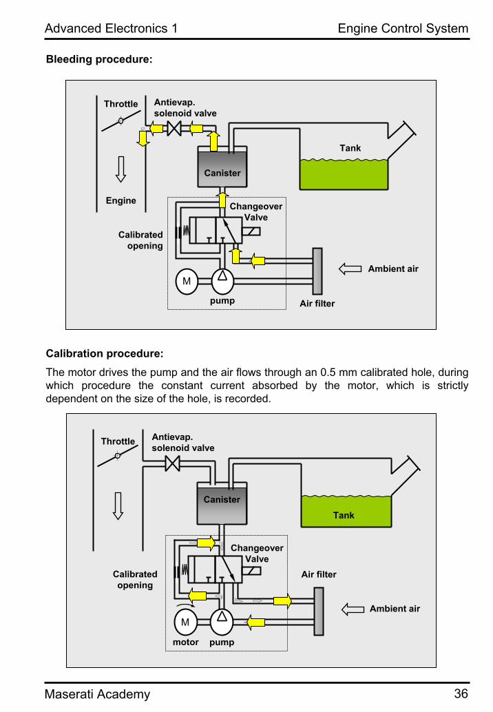
For canister bleeding the anti-evaporationvalve is opened and the engine vacuumaspirates fresh air through the filter and the canister.
When the system is in standby conditionthe fuel tank breathes through the canister, the changeover valve and the air filter.
Engine Control System
Maserati Academy
Advanced Electronics 1
36
pump Air filter
Changeover Valve
Calibrated opening
M
Canister
Tank
Antievap. solenoid valve
Throttle
Engine
Ambient air
Bleeding procedure:
Calibration procedure:The motor drives the pump and the air flows through an 0.5 mm calibrated hole, duringwhich procedure the constant current absorbed by the motor, which is strictlydependent on the size of the hole, is recorded.
pump
Air filter
Changeover Valve
Antievap. solenoid valve
Throttle
motor
Ambient airM
TankCanister
Calibrated opening
Engine Control System

Maserati Academy
Advanced Electronics 1
37
Test procedure:The changeover valve is open and the anti-evaporation valve is closed. The canister/tank air circuit is set and held under pressure by the pump. The absorbedcurrent is measured and compared to the reference current value.
pump
Changeover Valve
Calibrated opening
M
Canister
Antievap. solenoid valve
Throttle
Engine
Air Inlet
Air filter motor
Tank
• engine rpm = 0• altitude < 2800m• engine temperature (off) > 3.8 °C• ambient temperature 3.8 ° < T < 35,.3 °C• fuel level from 15% to 85%• vehicle speed = 0 Km/h• battery voltage 10.95 < Vb < 14.5• Correct operation of the altitude, engine temperature, vehicle speed, air
pump, and anti-evaporation valve sensors.• Driving cycle of at least 600 seconds, then• Engine off for at least 5 hours, then• Driving cycle of at least 800 seconds• Test launched several seconds after KEY OFF
Engine Control System
The test can also be launched manually by means of the short trip (cycle environment in SD3)

Maserati Academy
Advanced Electronics 1
38
t
Leakage= 0.5 mm
Leakage > 1 mm
2.5 kPa
Sealed systemReference current
Reference leakage0.5 mm
t1 t2 t3
I
Pump motor current absorption
The first part of the curve is relative to the calibration phase: the system performscalibration using the reference current. This is the absorbed current of the pumpcorresponding to a leak through a calibrated 0.5 mm hole.
The second section of the curve is relative to the test phase:
• When the system is sealed the pump current increases proportionally withpressure in the system (blue curve).
• When the system has a leak corresponding to an 0.5 mm hole (critical leakage) the current reaches the maximum value at critical point t3 (yellow curve).
• When the system has a major leak (more than 1 mm) the current never reachesthe reference value (red curve).
• The test terminates in a couple of minutes, depending on various factors suchas the fuel level in the tank.
• When a leak has been detected the ECU saves a DTC (P0455, P0456) and illuminates the MIL warning light
Engine Control System

Maserati Academy
Advanced Electronics 1
39
INJECTOR
The fuel injector is composed of a needle that is forced against the seat to prevent the inlet of fuel in aspiration. The needle is integral with a magnet. Next to the magnetthere is a solenoid which, when energised, interacts with the magnet thereby forcing itupward and with the magnet also the needle.The injector opening time is proportional to the quantity of fuel supplied in aspiration.
A change in the current that creates the magnetic field results in voltage that tends tooppose the current change. This is the reason for the counter-voltage peak that can bemeasured on an oscilloscope.
The injector is active when the pin from the ECU is connected to ground.
Technical data:• flow rate: 239.7 g/min• internal leakage: 2 mm3/min• voltage: 12 V• injection time: 2-4 ms with engine idling• injector resistance: +-12 Ohm (20°C)
Engine Control System

Maserati Academy
Advanced Electronics 1
40
"Rich" mixture
"Lean" mixture2
1
Lambda factor (Excess oxygen)
Oxy
gen
Sen
sor C
urre
nt[m
A]
0.7 1 1.3 1.6 1.9 2.2
3
2
1
-2
0
-1 1
2
BROAD BAND OXYGEN SENSOR (Bosch LSU)
The pumping or measuring cell is maintained with a stoichiometric A/F ratio. In the presence of excess oxygen in the exhaust gas, positive pumping current makes itpossible to remove said excess oxygen. The opposite situation occurs with richmixtures. The pumping current therefore indicates the stoichiometric ratio and the concentrationdifference generates a current.
Technical data:• power supply 12 V• heater power: 10W• operating temperature: 750 °C• heater control: 0-12 V in PWM
LSU type broad band oxygen sensors always function in CLOSED LOOP mode exceptduring the "light off" period and for very short intervals during transients.
Engine Control System

Maserati Academy
Advanced Electronics 1
41
Heater efficiency check:Disconnect the sensor and use a multitester on the impedance scale to measure the resistance between pins 3 and 4. The measured value should be 3.2 Ohm.
Trimming resistor check:Disconnect the sensor and using a multitester set to the impedance scale measure the resistance between pins 2 and 6. The measured value should be 300 Ohm.
Pumping current check:The pumping current is converted by the ECU into voltage, which can be analysedusing an oscilloscope. This voltage signal varies continuously between +300mV and -300mV.
On SD3 the converted voltage measured is 1.5V and can be checked in the OBD parameters
Closed loop check conditions: it is possible to check feedback on the front oxygensensors with engine T° of 90°C at idle speed
Engine Control System

Maserati Academy
Advanced Electronics 1
42
TWO-LEVEL OXYGEN SENSOR (Bosch LSF)
The oxygen sensor measures the A/F ratio in burnt exhaust gas with respect to a stoichiometric composition. In practical terms, the sensor measures the difference in the concentration of oxygen in the exhaust gas and in ambient air.Once the sensor has been heated by its internal heating circuit, the oxygen on the external electrode is broken down into ionic form by the catalytic film of the electrode. A similar process occurs on the internal electrode with ambient air. The concentrationdifference generates a voltage signal in mV. These sensors are capable of definingonly whether the mixture is rich or lean, without providing anyquantitative information. The sensors are therefore also known as on-off or LSF sensors.
0.8 0.9 1 1.1 1.2
1000
800
600
400
200
0
1 2
Lambda factor (Excess oxygen)
Sen
sor V
olta
ge[m
V]
"Rich" mixture
"Lean" mixture2
1
Technical data:• Power supply: 12 V• heater power: 7 W• heating current: 2.1 A• heating control: PWM 0-12 V• exit: 0-900 mV
Closed loop check conditions: feedback on the rear oxygensensors can be checked with a road test, by means ofacquisition with SD3.
Engine Control System

Maserati Academy
Advanced Electronics 1
43
Air FlowSensor
Injectors
λ-post-catsensor
Fault managem
ent
MIL
Catalytic converter
Catalytic convertermonitoring
λ-control
λ-post-catsensor
λ-limit-control
CalculatedInjection
time*
CATALYTIC CONVERTERS MONITORING
Pre-cat oxygen sensor = LSUPost-cat oxygen sensor = LSF
Engine Control System
Lambda > 1 : Mixture = leanLambda = 1: Mixture = correctLambda < 1 : Mixture = rich
In accordance with regulations, the engine must always* runwith Lambda = 1 (correct mixture)
(*): except during a brief interval after cold starting and during short-term transients.
To obtain and maintain a correct F/A mixture the Lambda monitoring system mustfunction in "Closed Loop" mode (with feedback). The "open loop / closed loop" state can be checked by means of tester SD3.

Maserati Academy
Advanced Electronics 1
44
• The "Short Term Fuel Trim" is expressed as a percentage correction of the fuelquantity.
• When the mixture is too lean or too rich, the ECU continues to make correctionsuntil the limit is reached (in both directions).
• The ECU transfers the Short Term Fuel Trim value continuously and progressively to the "Long Term Fuel Trim" (= integral correction). The Motronicsubsequently corrects the carburetion map and adapts it by "moving it".
• A "Long Term" correction corresponds to a 1% correction of the map (positive or negative) and is saved in the ECU.
• When the Long term Fuel Trim reaches a certain limit (usually a 10% variation, although this depends on the standard), an error code is stored and the enginecheck warning light illuminates.
• This condition indicates the presence of a problem in the air or fuel system (malfunction of air flow meter, injectors, oxygen sensors, exhaust, EVAP system...).
• The Long Term Fuel Trim is specific for engine idling and for low/high engineload conditions.
• The Fuel Trim is specific for both cylinder banks and can be verified with the SD3 tester.
• The expression Fuel Trim is used in various regulations to indicate the correction of the quantity of fuel based on information supplied by the oxygensensors.
• The ECU compares the real Lambda value measured by the pre-cat sensor withthe target Lambda value.
• To maintain the correct stoichiometric air/fuel ratio the ECU calculates a correction of the injection quantity in real time.
• This real time correction is designated "Short Term Fuel Trim".
Fuel trim:
PRE-CAT LAMBDA VALUE MONITORING
The Lambda value for the two banks upstream from the catalytic converters ismonitored by means of LSU type sensors (broad band oxygen sensors). Thesesensors make it possible to measure the Lambda value in real time and with high precision.The measured Lambda value is subsequently compared by the ECU with the valuecalculated in accordance with a model and any changes are compensated by means ofthe "Fuel Trim" strategy (Closed Loop operation)
Engine Control System

Maserati Academy
Advanced Electronics 1
45
Engine Control System
• The fuel trim self-learning process will be deactivated in case any DTCs regarding the engine control system are stored inside the ECU. The self-learning will pick up againonce the problem is solved and the error cleared.
• The various self-learning values will be reset when the DTC memory of the engine ECU is cleared.
• The self-learning is interrupted while the canister purgesolenoid valve is activated.
• Fuel Trim is very usefull diagnostic information which will get lost when the ECU memory is cleared!
The SD3 displays various Fuel Trim self-learning values (parameter environment):
• “Additive correction of the idle mixture adaptation”: this information regardsthe additive fuel adaptation applied by the Motronic for idling conditions. The range of the self-learning correction lies between -10,20% and +10,20%. “0”means there is no correction. For example: a value equal to +1% means that the Motronic applies a positive correction. With the basic fuel map the engine isrunning to lean; consequently the Motronic increases the amount of injected fuelwith 1 %. The normal range for the idle fuel correction is between -2,5% to+2,5%. A value outside this range indicates a possible problem with the air/fuelcircuit.
• “Fuel self-learning at low/high engine load”: these are multiplicative valuesfor low/high engine load conditions (“1.000” means there is no correction). The range for this self learning value lies between 0,703 and 1,296. A value higherthan 1 means that the engine is running to lean with the basic mapping; a valuelower than 1 means that the engine is running to rich with the basic mapping. The Motronic multiplies the amount of injected fuel with the indicated value in order to maintain the target lambda value.
• “Actual self-learning”: indicates which of the various self-learned fuel maps isactually used in function of the actual engine running conditions.

Maserati Academy
Advanced Electronics 1
46
SLOW DOWN STRATEGY
• The catalytic converters may be damaged if the temperature rises excessively.
• A mathematical model integrated in the ECU makes it possible to calculated the temperature of the catalytic converters in real time.
• The parameters utilised for the calculation are as follows: engine coolanttemperature, ambient temperature, engine load, ignition advance and Lambda value.
• The calculated temperature allows the ECU to protect the system from seriousproblems by implementing suitable strategies
• When the calculated temperature reaches 980°C the Slow Down warning light flashes on the dashboard to alert the driver to the presence of a critical situation.
• When the calculated temperature reaches 1040°C the Slow Down warning light remains steadily illuminated and the ECU switches off the engine. Highercatalytic converter temperatures would damage the converters and may result in a fire outbreak.
Engine Control System
POST-CAT LAMBDA VALUE MONITORING
The Lambda value down-stream of the catalytic converters is monitored by LSF typeoxygen sensors (two-level sensors). These Oxygen sensors are less precise than LSU type sensors, and they are utilised primarily for diagnostic purposes.The Lambda value down-stream from the catalytic converters is used to:
• Check proper operation of the catalytic converters: In the event ofdetection of low efficiency of the catalytic converters, the Motronic ECU stores a DTC and illuminates the MIL warning light.
• Check proper operation of the Oxygen sensors up-stream of the catalyticconverters (plausibility check).
• Provide a minor contribution to the Fuel Trim.

Maserati Academy
Advanced Electronics 1
47
0.9 0.95 1.0 1.05 1.1
200
400
600
800
1000
mVSe
nsor
out
put v
olta
geEmissions without catalytic treatment
Emissions withcatalytic treatment
NOx
NOx
HC
CO
HC
CO
Exha
ust e
mis
sion
s
λ Area Control
Lambda Factor
λ SensorOutput voltage
Influence of the Lambda value on exhaust emissions (pre- and post-cat):
NOx0,15 g/km
HC+
NOx
0,5 g/km
HC+
NOx
0,97 g/km NOx 0,08 g/km
HC0,2 g/km
EURO 32000
EURO 11992
HC 0,1 g/kmCO
2,3 g/km
CO
2,72 g/km
CO
2,2 g/km
CO
1,0 g/km
EURO 21996
EURO 42005
52%
81% 85%
37%
100 %
36%
19%
100%
0%
20%
40%
60%
80%
100%
Emis
sion
Lev
el
Evolution of EURO regulations:
Engine Control System

Maserati Academy
Advanced Electronics 1
48
EMISSIONS CONTROL (M139):
The control of emissions in applications is performed in the followingconditions:• Engine idling, steady state• Warm Engine• Lambda control inactive (open loop)
Values:• HC: 40 - 300 ppm• CO: 0.25...1.00 %• O2: 0...1.5 %• CO2: there is no reference value, CO2 is proportional to the quantity of fuel
consumed. CO2 falls when combustion is incomplete
In the event of misfiring caused by failure to ignite the mixture, the HC value increasessignificantly (e.g. around 2000 ppm when one cylinder fails to fire).
Idle speed carburetion parameters:
• engine speed (nmot): 660..740' • load (rl): 15..35% • throttle (wdkba): 2..4% • RH and LH bank injection time (ti_b1/b2): 2..4 ms • air flow read by air flow meter (ml): 20..35 kg/hr• LH and RH mechanical timing (wnwkwas/2): 106..124°CS • accelerator pedal (wped): 0..100% • throttle self-learning (lrnstep): 0 or 11• lambda control feedback (fr): 0.92..1.08 • advance (zwout): -10°..+10°CS • engine temperature (tmot): 90..100°C • initial LH and RH mechanical timing self-learning (dwnwrp0e/2) • fuel at minimum self learning LH and RH (rkat/2): -2.5..+2.5 • aspirated air temperature (tans): 20..60°C • front LH and RH oxygen sensor (lamsoni/2): 0.98..1.02 • rear LH and RH oxygen sensor (lamsonh/2): 0.95..1.05 • mechanical phase self-learning OK LH and RH (B_phad/2): true/true
Engine Control System

Maserati Academy
Advanced Electronics 1
49
3
1
4
2 2
SECONDARY AIR SYSTEM
5
1. Solenoid Valve2. Pneumatic valves3. Vacuum tank4. Secondary air pump5. System for secondary air injection into
cylinder heads (wet sump engine)
In order to reduce emission levels in accordance with the prescriptions set down in the various regulations, the catalytic converters must reach their operating temperature very rapidly following a cold start.
One way of speeding up heating of the catalytic converters is to retard the ignitionadvance when the engine is cold; another method is to install a secondary air injectionsystem.
During the "light off" period (brief interval after cold starting during which the catalyticconverter is inoperative) the engine runs in "Open Loop" mode with a rich mixture(Lambda ≅ 0.75). Combustion is incomplete in the cylinder and the exhaust gas contains a high concentration of HC and CO.
By injecting air in the vicinity of the exhaust valve a chemical reaction occurs in the duct between the HC, CO (both of which are present in excess) and the O2 present in the injected air. In this manner the unburnt fuel is subsequently burnt in the exhaustsystem.
The heat generated by this process causes rapid heating of the catalytic converters; Moreover, emissions are significantly reduced thanks to this "completion" of the combustion process.
The secondary air system is composed of an electric pump controlled by a relay, twopneumatic valves that close the line when the system is inoperative, and a solenoidvalve that controls the pneumatic valves by means of the vacuum provided by a connection with the plenum chamber.
The secondary air system is activated by the ECU after a cold start and only whenengine temperature is in the range -7 to + 40°C. In these conditions the engine runs in "Open Loop" conditions.
During this phase the Oxygen sensors signal is utilised to calculate the temperature ofthe catalytic converters, utilising a mathematical calculation model.
Engine Control System

Maserati Academy
Advanced Electronics 1
50
Injector
Throttle
Sparkplug
Air flow meter
Accelerator
pedal
AirMain path
Spark
Fuel
Sparkplug
Enginerpm + charge
withvariators
rawadvance
basicadvance
deliveredadvance
- Raw advance calculationfrom advance maps
- takes account of variatorsactuation
- Knock limit shift factor ..
- Lambda correction
- Catalytic converterheating delta
- Knock control delta
- Pass-by delta (noise)
Integrates all previousdelta valuesThis is the mainfunction.
- An advance delta can be supplied
3rd FUNDAMENTAL PARAMETER: SPARK ADVANCE
Spark path:
Spark advance calculation:
Engine Control System

Maserati Academy
Advanced Electronics 1
51
Three running conditions can be identified, each of which characterised by an advancepath:• Starting: specific maps are provided• With map advance: the advance is as specified in the map• With advance that differs from map
Reasons for advance other than that specified in the map:
• Torque reserve• Catalytic converter warm-up• Anti-flutter strategies• Comfort - handling strategies• Engine protection strategies
Engine Control System

Maserati Academy
Advanced Electronics 1
52
RPM SENSOR
The RPM sensor is a variable reluctance transducer (also known as a pick-up or inductive sensor) located in proximity of the tone wheel keyed to the crankshaft.The tone wheel has 58 (60-2) teeth.
Electrical characteristics:Resistance = 1134 ÷ 1386Ω (20°C).
The prescribed gap between the tip of the sensor and the tone wheel to obtain correctreadings is between 0.5 and 1.5 mm. The output voltage varies with the rotation speed.
1) Projection of the tone wheel section
2) Waveform read by the sensor
3) First tooth after space
4) Signal status change
The RPM sensor is a passive transducer (no signal output when the tone wheel is stationary); this means that the position of the crankshaftcannot be identified when the engine is stopped.
It is extremely important to ensure the sensor is correctly fixed in orderto obtain efficient engine operation. Movements, vibrations,... etc. ofthe RPM sensor can create engine problems, even though the RPM signal seems to be OK when the engine is idling.
Engine Control System
The engine RPM signal must alwaysincrease in correspondence with the tone wheel toothspace! (if the signaldecreases at this point this means the sensor polarity is inverted)

Maserati Academy
Advanced Electronics 1
53
TIMING SENSOR
The timing sensor is a Hall-effect transducer fitted in correspondence with a tone wheel with four cams on the camshaft.In normal conditions the timing sensor output signal is 5V, but when the magnetic camis aligned with the sensor the signal is lost, thereby informing the ECU of the position of the camshaft (the ECU reads the downward flanks of the timing signal)The timing sensor is an active transducer. This means that the position of the camshaftis recognised even when the engine is stopped. The timing signal is utilised torecognise the position of the engine and for the VVT system.
Error Description Criterion MIL (EURO) MIL (USA)
P1323 Alignment betweentiming signal and RPM signal
Timing signalexcessivelyadvanced
After 3 Driving-cycles
After 2 Driving-cycles
P1339 Alignment betweentiming signal and RPM signal (B2)
Timing signalexcessivelyadvanced
After 3 Driving-cycles
After 2 Driving-cycles
P1324 Alignment betweentiming signal and RPM signal
Timing signalexcessivelyretarded
After 3 Driving-cycles
After 2 Driving-cycles
P1340 Alignment betweentiming signal and RPM signal (B2)
Timing signalexcessivelyretarded
After 3 Driving-cycles
After 2 Driving-cycles
Engine Control System
The electrical timing signal is composed of four high parts (2 x 140° + 2 x 40°) and fourlow parts (2 x 40° + 2 x 140°), the timing signal is electrically symmetrical!

Maserati Academy
Advanced Electronics 1
54
54° = 9 teethTone wheel hole <->TDC Cyl.1 = 54° CR (9 teeth)
Advance =10°=1.5 teeth
Coil charge control
Tone wheel 2 missingteeth
RPM sensorsignal
Coil signal for Cyl. 1 2nd downwardflank after 2
missing teeth = electrical zero
point
TDC of cyl. 1
ENGINE ELECTRICAL TIMING
Engine Control System
• The tone wheel on the crankshaft has 58 teeth (60 teeth minus two missingteeth)
• The zero point for the ECU is constituted by the second descending tooth flankafter the space measured by the engine RPM signal. The ECU detects aninterval between teeth that lasts more than twice the time of the previous and subsequent intervals.
• The mechanical top dead centre of the first cylinder is exactly 9 teeth (54 degrees) after the electrical zero point of the RPM signal.
• In order to recognise the position of the engine, the ECU checks the timing signal at the time of the zero point identified by the RPM signal.
• It is essential, in order to read the engine position, that when the zero point ofthe RPM signal corresponds with a high signal of the camshaft, the next zero point corresponds to a low signal (see diagram on next page).
• Recognition of the engine position is indispensable for operation of the sequential ignition and injection system.
• The ECU performs a check of the alignment between the RPM signal and the timing signal. The applicable regulations allow a tolerated maximum "shift" of10° in both directions. When the engine exceeds this tolerance, the Motronicsaves a DTC and illuminates the MIL warning light.

Maserati Academy
Advanced Electronics 1
55
140° 40°
360°
W N W SPS1=279°W N W SPS0=99°
P unto m orto e lett.(PM S cil. 1)=60°=10 dentiA nticipo=0°
Prim aaccensione
Prim ainiezione
ti=tem po iniezione
Accensione Cilindri
Iniezione cilindri
R uota 4dentiR uotafonicaR uota 4denti
Electrical tone wheel4 tooth electricalwheel
40° 40° 140° 40° 140° 140°
WNWSPS_0
WNWSPS_1
WNWSPS_2
WNWSPS_3
360°
Theoretical timing referred to the negative tooth flanks of the 4-tooth wheel.
The WNWSPS are offset by 180°from one to the next
Correcttiming
(1 solid-1 void)
Dimensions
Engine Control System

Maserati Academy
Advanced Electronics 1
56
TIMING VARIATOR SOLENOID VALVE
Each Variable Valve Timing (VVT) actuator is regulated by a solenoid valve thatcontrols oil delivery to the advance chambers and to the retard chambers. The solenoidvalves are controlled directly by the Engine Control Node (NCM) by means of a PWM signal (pulse width modulation) and on the basis of programmed mapping (whichdepends on the engine load and RPM). The engine control module constantly monitorsthe actual position of the VVT-actuators by comparing the signals from the crankshaftposition sensor and the camshaft position sensors. When the oil control solenoid valve is in its rest position, oil delivery is connected to the retard line and the advance side ofthe circuit is connected to the sump.
Oil delivery
To VVT actuator (advance)
To VVT actuator(retard)
50°EXHAUST INTAKE
TIMING VARIATOR ACTIVATION
Engine Control System

Maserati Academy
Advanced Electronics 1
57
IGNITION COIL
The ignition coil is of the magnetic closed circuit type. The windings are housed in a plastic casing immersed in epoxy resin and positioned one on top of the other around a central ferrous core.
The Motronic activates the power stage (thanks to a series of transistors) on the coil forthe necessary charge time to bring the primary winding current to its maximum value. The energy stored in the coil is proportional to the charge time. At the time of ignition (which corresponds to the required advance) the power stage interrupts the flow of current on the primary winding. At this point the significant changein the magnetic field generates a voltage on the secondary winding. When this voltageis applied to the spark plug it results in the generation of a spark.
Technical data:• Power supply: 12V• Primary winding current: 7 A• Charge control: 5V• Dwell time: 2.8 ms• Secondary winding voltage: 30 kV• Energy: 33-37 Mj• Primary winding resistance: 0,73 Ohm (internally)• Secondary winding resistance: 9,6 kOhm (internally)
Engine Control System

Maserati Academy
Advanced Electronics 1
58
Ground (common) Pilot signal (5V)
Power supply +12V (common)
The ignition coil is made up of two coupled windings. The generation of a voltage peakin the primary winding, trigged by the ECU, generates an overvoltage peak and the transit of current on the secondary winding (which is discharged through the sparkplug).
+12V
ECU
GROUND
Voltage on spark plugs
Engine Control System

Maserati Academy
Advanced Electronics 1
59
ELDOR COILApplication of Eldor coils on the vehicle:
• From assembly 24275 for the Quattroporte
• All GranTurismo cars
Benefits of the Eldor coil:
• Simplification of fixing on the cylinder head covers.
• Provision to accommodate future developments for knock and misfiringdiagnostics.
• More stable combustion at high revs.
1 2 3 4E
C
ECU+15
Pin 3 = 5V control signal from ECU
Engine Control System
The Eldor coil requires a specific spark plug. This results also in a modification of the cylinder head for all engines equipped with Eldor coils. Always check the correct match when replacing spark plugs.

Maserati Academy
Advanced Electronics 1
60
MISFIRING
• In compliance with OBD-II / EOBD standards it is obligatory to detect the absence of combustion.
• For this reason a monitoring strategy has been developed that allows the ECU to detect and identify misfires.
• A misfire causes fluctuations of the crankshaft rotation speed that are read bythe RPM sensor.
• For misfiring control, changes in crankshaft rotation speed are monitored whenthe engine is running smoothly.
• Aware of the position of each piston - by means of the timing sensor - it ispossible to connect a low peak in rotation speed to a given cylinder.
• A misfire error code is saved in the memory when a critical number of misfiresare detected in a given time interval.
• DTC P0300 indicates unspecified misfires.• DTC P0301-P0308 indicates misfires by cylinder from 1 to 8.• The misfiring control strategy is active only when the NCM has completed its
self-learning procedure.• A specific strategy prevents fuel starvation from being interpreted as misfiring.
Exhaust gas monitoring upstream from catalytic converter:
Misfiring causes:• Reduction of CO2• Radical increase in HC• Increase in CO• Temperature reduction
Misfiring can seriously damagethe catalytic converters!
Engine Control System
Acc
eler
atio
nM
easu
rem
ent
inte
rval
(µs)

Maserati Academy
Advanced Electronics 1
61
Connector
Crankcase
Screw
Chassis
Seismologicalmass
Piezo-ceramicelement
V = VibrationF = Compression forces
KNOCKING SENSOR
Knocking is caused by detonation, uncontrolled, fast combustion with significantpressure gradients, including local gradients caused by detonating rather thanexplosive combustion of the mixture due to self-ignition phenomena.This problem can be solved with retarded ignition, i.e. by "removing the sparkadvance". The Motronic control unit detects detonation in individual cylinders thanks topiezoelectric sensors that generate an alternating current. The signal is subsequentlyanalysed, filtered, integrated and converted. Subsequently the advance on the cylinder subject to knocking is retarded and thenreturned gradually.
The ECU activates the electronic knockingcontrol strategy when the enginetemperature reaches 40°C and the engineload is more than 30%.
Engine Control System

Maserati Academy
Advanced Electronics 1
62
Layout of sensors on crankcase:
1
2
3
4
Timing side
RH
ban
k
LH b
ank
Sensors positioning
Cylinders 1 - 2
Cylinders 5 - 6
Cylinders 7 - 8
Cylinders 3 - 4
2
1
3
4
Za: correct advance (curve 1)Zb: excess advance can cause knocking in the cylinder (curve 2)Zc: insufficient advance greatly reduces cylinder compression (curve 3)
Curves showing effective pressure in the combustion chamber in relation to the ignition angle:
For correct operation of the knockingsensors it is important that assemblybe performed in compliance with the correct tightening procedure.
Engine Control System

Maserati Academy
Advanced Electronics 1
63
Connector
Terminals
Screw frame
O-ringInsulating line
Insulating coverNTC element
TEMPERATURE SENSOR
Negative Temperature Coefficient (NTC) type temperature sensors form part of a voltage division circuit integrated in the ECU and connected to a 5V power supply. The sensor voltage varies in proportion with impedance and provides temperature information to the ECU. A strategy integrated in the ECU filters linearity errors betweenthe temperature and the impedance.
Impe
danc
e[k
Ohm
]
0.01
0.1
1
10
-20 0 20 40 60 80 100
Temperature [°C]
Impedance at 20 °C: 2.5 kOhmImpedance at 100°C: 0.186 kOhm
Engine Control System
Maserati engines use two coolant temperature sensors: upstream from the thermostatic expansion valve and on the cooler. This layout allows the ECU to controlproper operation of the thermostatic valve and carry out a plausibility check of the temperature sensors (at KEY ON with cold engine the temperature measured by the two sensors must be identical).
DTC P0128 indicates a problem of plausibility between the two sensors.

Maserati Academy
Advanced Electronics 1
64
COMMUNICATION FLOW OF PARAMETERS RELATIVE TO THE ENGINE CONTROL SYSTEM
Input/output with sensor/actuator included
Input/output with sensor/actuator not included
B-CAN node
C-CAN node
B-CAN signal
C-CAN signal
Non-CAN signal
n = number of signals
Engine warning light (MIL) activation signal:
Engine Control System

Maserati Academy
Advanced Electronics 1
65
Engine rpm signal:
Engine Control System

Maserati Academy
Advanced Electronics 1
66
Vehicle speed signal:
Engine Control System

Maserati Academy
Advanced Electronics 1
67
Engine coolant temperature signal:
"Slow Down" warning light activation signal:
Engine Control System

Maserati Academy
Advanced Electronics 1
68
Fuel level signal:
Engine oil minimum pressure signal:
Engine Control System

Maserati Academy
Advanced Electronics 1
69
Engine oil minimum level signal:
A/C compressor activation signal:
Engine Control System

Maserati Academy
Advanced Electronics 1
70
Ambient temperature signal:
Engine Control System

Maserati Academy
Advanced Electronics 1
71
Immobilizer signal:
Engine Control System

Maserati Academy
Advanced Electronics 1
72
DIAGNOSTICS
Tester (SD3)Enginecontrolmodule(NCM)
CAN / K-line
Communication protocol
SCAN TOOL
KWP 2000
SCAN TOOL:Scan Tool is the communication protocol between the tester and the ECU thatdescribes and controls diagnostics of systems or subsystems relative to exhaustemissions. Scan Tool was a spin-off from CARB (California Air Resources Board) and EPA (Environmental Protection Agency), two US environmental protection agencies.Subsequently Scan Tool was standardised and defined by SAE (Society of AutomotiveEngineers) and in an equivalent manner also by ISO (International Organisation forStandardization). The relative standards are: SAE J1979, SAE 2012 and ISO 15031-1/4/6.These standards were implemented in order to standardise diagnostics in accordancewith the US OBD-II (On Board Diagnostics II) standard and the European derivative version EOBD (European On Board Diagnostics). As from 2008 the regulations will beupdated with the issue of the new ISO 15765-4 standard.
KWP 2000:For diagnostics of vehicle systems that are not necessarily associated with emissions, the automotive sector has developed a common standard: Keyword Protocol 2000. KWP 2000 is strongly anchored to the Scan Tool philosophy and the two standards are partially overlapping.KWP 2000 is not compulsory but automakers are strongly encouraged to work in compliance with this standard as far as possible.
Engine Control System

Maserati Academy
Advanced Electronics 1
73
Diagnostic Trouble Codes (DTC)
DIAGNOSTICS
An error indicates a malfunction of a system, subsystem or component and is detectedand saved by means of the diagnostic function.The driver is alerted to the error by illumination of the MIL warning light only when the malfunction of the subsystem or component may result in worsening of pollutantemissions. Specifically, the warning light is illuminated after 2 (OBD-II) or 3 (EOBD) times in which the error is detected.There are two types of error code: ISO / SEA controlled codes and manufacturercontrolled codes:
ISO / SAE controlled codes:These error codes are those in relation to which the automotive industry hasestablished uniformity, so they are identical for all automakers. Standardisation wasimposed by ISO / SAE and specified in the various standards. OBD-II / EOBD standards use ISO / SAE controlled codes for diagnostics of emission-related systems.
Specific manufacture controlled codes:The standard provides a sequence of codes that are placed at the disposal of individualmanufacturers. This means that the manufacturer is free to assign the meaning itchooses to these codes. This may be necessary because of the differences betweenthe systems or implementations of each individual automaker. Manufacturers are anyway encouraged to follow the same subdivisions as for the ISO / SAE controlledcodes.
Error codes (standard acronym: DTC) are divided into four groups:
PXXXX (Powertrain): Errors relative to the engine and powertrainBXXXX (Body): Errors related to the vehicle bodyCXXXX (Chassis): Errors related to the vehicle chassisUXXXX (Undefined): Errors related to the communication network
Each group contains ISO / SAE controlled codes and codes freely assignable by the manufacturer.
Note: with regard to the technical terminology utilised to describe each error code (DTC), manufacturers are obliged to adhere to terminology in compliance with standard SAE J1930
Engine Control System
DIAGNOSTICSWhen diagnostics is completed a flag is set and in the event of an error also the errorflag is set. Diagnostics can be:• continuous (e.g. misfiring, fuel self-learning)
• discrete (e.g. thermostat diagnostics). performed once per driving cycle.

Maserati Academy
Advanced Electronics 1
74
DIAGNOSTICS
Freeze Frame Data• When an error (DTC) connected to emissions is saved in the memory, the OBD-
II / EOBD system provides also a "Freeze Frame Data".• Freeze Frame Data provides information concerning the conditions relative to
the moment in which the DTC was detected.• The saved parameters are as follows: DTC, engine RPM, air flow rate, engine
load, Fuel Trim, engine coolant temperature, pressure in the plenum chamber, loop status (open/closed), vehicle speed.
• This is valuable information for diagnostic purposes that is lost as soon as the DTC is deleted!
Engine Control System
Diagnostic Trouble Code Classes: DTCs are divided into various classes. The class indicates: whether the errorilluminates the MIL warning light, after how long the error is acknowledged or notacknowledged, whether the error must be saved in the memory, the validation and de-validation time of the MIL warning light, whether the error calls for storage of FreezeFrame Data,...
DTC statusThe DTC status can be "Pending" or "confirmed":
• Pending: a pending DTC is defined as the DTC stored after the initial detection of the problem (e.g. after a single driving cycle), prior to illumination of the MIL warning light and in compliance with the various standards.
• Confirmed: defined as the DTC stored when OBD-II / EOBD has confirmed the existence of the problem. The MIL warning light illuminates in compliance withthe various standards.
Deleting a confirmed DTC:The OBD-II system can auto-delete a DTC if the indicated fault has not been detectedduring at least 40 warm-up cycles.
Diagnostic Readiness Status:In compliance with SAE J1979, the OBD-II system indicates a "Complete" or "Incomplete" status for diagnostics of each component or subsystem that is monitoredand after the errors memory has been cleared for the last time.All constantly monitored components or systems must always indicate "complete".All components or systems that are not monitored continuously (discrete diagnostics) must immediately indicate "complete" when the diagnostic of the component or system in question has been fully executed and no faults have been detected.

Maserati Academy
Advanced Electronics 1
75
DIAGNOSTICS
What does a Diagnostic Trouble Code mean?A DTC tells us something about the condition of an electrical signal monitored by a control unit. Clearly the OBD-II / EOBD system is only able to detect electricalproblems rather than mechanical problems. In many cases however also mechanicalproblems can be detected inasmuch as they exert an influence on certain electricalparameters.Example: OBD-II / EOBD is not capable of detecting a jammed throttle because thereis no DTC for "jammed throttle". However this mechanical problem causes a relatedelectrical problem: the throttle position sensor signal will no longer correspond with the ECU control signal for the motor-driven throttle. The saved DTC indicates: throttleposition sensor - signal not plausible. At this point the diagnostic engineer can conclude that the problem with the sensormay be caused by a jammed throttle.
There are 4 error code categories:
Minimum:If the measured or calculated value is below a minimum threshold, for example a sensor signal is below 0.5V (one possible cause may be a ground fault), or the value ofa self-learning procedure that arrives at the minimum value.
Maximum:The measured or calculated value is above a maximum threshold; this may be anelectrical problem (short circuit to power supply) although not necessarily; it may alsobe a counter value that exceeds a critical threshold level. Example: The DTC thatindicates a misfire in a given cylinder is not saved after the first misfire, but only when a certain number of misfires are detected in a given time period.
Signal:The signal is absent continuously or intermittently: one cause could be an open circuitor bad contact on the connector.
Plausibility:The ECU measures a signal that is in its normal band, but the value does notcorrespond to the expected value (according to information received from anothersensor or according to a mathematical model). The ECU reads a value and checks it. The ECU concludes that in the given conditions the measured value cannot be correct. Example: the air flow meter signal does not correspond with expectations on the basisof the opening of the throttle and the engine RPM. The cause may be that the air flow meter is contaminated.
For diagnostics of a component or subsystem, only one code of these fourcategories can be saved at a time.
Engine Control System

Maserati Academy
Advanced Electronics 1
76
P0XXX: SAE / ISO controlledP00XX: Fuel and air measurement and auxiliary emissions controlP01XX: Fuel and air measurementP02XX: Fuel and air measurementP03XX: Ignition or misfire systemP04XX: Auxiliary emissions controlP05XX: Vehicle road speed, idle speed and various inputs controlP06XX: ECU and various inputsP07XX: TransmissionP08XX: TransmissionP09XX: TransmissionP0AXX: Hybrid propulsionP0BXX: ISO / SAE reservedP0CXX: ISO / SAE reservedP0DXX: ISO / SAE reservedP0EXX: ISO / SAE reservedP0FXX: ISO / SAE reserved
P1XXX: Manufacturer controlledP10XX: Fuel and air measurement and auxiliary emissions controlP11XX: Fuel and air measurementP12XX: Fuel and air measurementP13XX: Ignition or misfire system P14XX: Auxiliary emissions controlP15XX: Vehicle road speed, idle speed and various inputs controlP16XX: ECU and various inputsP17XX: TransmissionP18XX: TransmissionP19XX: Transmission
P2XXX: SAE / ISO controlledP20XX: Fuel and air measurement and auxiliary emissions controlP21XX: Fuel and air measurement and auxiliary emissions controlP22XX: Fuel and air measurement and auxiliary emissions controlP23XX: Ignition or misfire systemP24XX: Auxiliary emissions controlP25XX: Various inputsP26XX: ECU and various inputsP27XX: TransmissionP28XX: ISO / SAE reservedP2AXX: Fuel and air measurement and auxiliary emissions control
P3XXX: Manufacturer controlled and ISO / SAE reservedP30XX: Fuel and air measurement and auxiliary emissions controlP31XX: Fuel and air measurement and auxiliary emissions controlP32XX: Fuel and air measurement and auxiliary emissions controlP33XX: Ignition system or misfireP34XX: Deactivation of cylindersP35XX: ISO / SAE reservedP36XX: ISO / SAE reserved
DIAGNOSTICS
Various DTC subgroups:
Engine Control System

Maserati Academy
Advanced Electronics 1
77
DIAGNOSTICS
Various DTC subgroups (contd.):
P37XX: ISO / SAE reservedP38XX: ISO / SAE reservedP39XX: ISO / SAE reserved
B0XXX: ISO / SAE controlledB1XXX: Manufacturer controlledB2XXX: Manufacturer controlledB3XXX: Reserved
C0XXX: ISO / SAE controlledC1XXX: Manufacturer controlledC2XXX: Manufacturer controlledC3XXX: Reserved
U0XXX: ISO / SAE controlledU00XX: Electrical networkU01XX: Communication networkU02XX: Communication networkU03XX: Software networkU04XX: Data network
U1XXX: Manufacturer controlledU2XXX: Manufacturer controlledU3XXX: Reserved
Engine Control System

Maserati Academy
Advanced Electronics 1
78
OBDOBD--II / EOBD II / EOBD connectorconnector
The 16-pin diagnostic connector is standardised in accordance with OBD-II / EOBD standards (for Europe: from EURO 3 onward). The first Maserati with the 16-pin OBD-II / EOBD connector was the 3200GT of 1998. For vehicles with Florence electronic architecture (M139 and M145), the ODB-II / EOBD connector is located on the Body Computer. The diagnostic connector is the interface between the tester (SD3) and the various communication networks.
DIAGNOSTICS
OBD-II / EOBD connector
Quattroporte OBD-II / EOBD connector pinout:
Engine Control System

Maserati Academy
Advanced Electronics 1
79
In compliance with ISO / SAE standards, for all cars from MY08 onward, Scan Toolmust be available on the CAN line. For the Quattroporte from MY07 and Automatic, and for the Gran Turismo Maserati, a new pinout assignment for the OBD-II / EOBD connector has been introduced. This makes it necessary to use a new "Switch Matrix" diagnostic cable.
All diagnostics for cars with Florence architecture are performed with the SD3 tester!
Quattroporte MY07 Automatic and Gran Turismo OBD-II / EOBD connector pinout
Engine Control System
DIAGNOSTICS

Maserati Academy
Advanced Electronics 1
80
NABNAB
DIAGNOSTICS
Florence architecture (example: Quattroporte):
Engine Control System

Maserati Academy
Advanced Electronics 1
81
DIAGNOSTICS
In the case of an air flow meter malfunction the air flow is estimated in accordance withthe throttle opening angle (from maps)
In the event of a malfunction of both air flow meter and throttle, the air flow isestablished by a map exclusively in relation to engine RPM
=
= engine rpm
Recovery management in the event of a breakdown of critical components:
Safety
3 components of the engine control system are of fundamental importance for road safety:
• Accelerator pedal• Air flow meter• Motor-driven throttle
For this reason diagnostics of these three components is covered in greater detail!
Engine Control System

Maserati Academy
Advanced Electronics 1
82
Problem Component Solution
Speed different from 0but vehicle stationary ABS/ASR Update/renew ABS/ASR control
unit
Discharged Battery Check battery
Coolant temperaturesensor fault Coolant temperature Check/renew sensor
Coolant temperatureabove 100° Coolant temperature Cool down engine
Coolant temperaturebelow 5° Coolant temperature Warm up the engine
Air temperature below5° Air flow meter Take car to warm environment
Air flow meter fault Air flow meter Check/renew air flow meter
Accelerator pedalpressed Accelerator pedal Release the accelerator pedal
Faulty accelerator pedal Accelerator pedal Check/renew Accelerator pedal
CAN problem CAN network Check/Repair CAN network
DIAGNOSTICS
Starting problems, throttle self-learning not executed
Engine Control System

Maserati Academy
Advanced Electronics 1
83
Problem Component Solution
Immo not deactivatedwith key Immobilizer Press key
Uncoded key Immobilizer Encode key
ECU with incorrectimmo code Immobilizer Renew ECU CCM/IMMO/NBC
Discharge/Spikes Battery Check battery
Transmission F1 prevents enginestarting
TransmissionControl Unit F1
Check clutch position sensorCheck start relayCheck clutch solenoid valveDisengage gearCheck Transmission Control Unit F1
Burnt out fuses Fuses Check fuses/check system
Bad ground contact Chassis ground Check/test ground connections
Satellite anti-theftsystem active
Satellite anti-theftsystem Check satellite anti-theft system
DIAGNOSTICS
Starting problems: starter motor fails to turn
Engine Control System

Maserati Academy
Advanced Electronics 1
84
Problem Component Solution
Inertia switch has tripped Inertia Switch Reset inertia switch
Exhaust temperature toohigh Catalytic converters Allow car to cool
Low voltage on mainrelay Main relay Check wiring or main relay
Starter motor runningwithout cranking engine Starter motor
Check starter motor clutch forjamming or foulingCheck electromagnets
DIAGNOSTICS
Starting problems: Engine fails to start
Problem Component Solution
Engine too rich Air cleaner clogged Renew air filter
Engine too lean Leakage Check sealing efficiency of intakeduct
Incorrect air flow Air flow meter Check/Renew Air Flow Meter
Fuel temperature toohigh/Vapours in fuel rails Vapour lock Cool down engine
Insufficient fuel Fuel supplyDegreaser on injectors in aspirationphase during crankingCheck fuel pump
Engine Control System

Maserati Academy
Advanced Electronics 1
85
Robotized Gearbox Control System
Robotized Gearbox ControlSystemMarelli

Maserati Academy
Advanced Electronics 1
86
1
2
6
3
5
4
ROBOTIZED GEARBOX CONTROL SYSTEMThe specific feature of the system is that it can be integrated on a mechanicaltransmission without requiring any special modifications.The gearbox is operated by a servo system controlled by steering wheel paddle levers.
Steeringwheel
gearshiftpaddles assy.
Display
Reverse button
"Race" button
robotized gearbox
LAYOUT1. Hydraulic actuator
2. Solenoid valves
3. Power unit
4. Accumulator
robotized gearbox
LAYOUT
1. Clutch Position Sensor on ClutchHousing (Sofast III)
2. Gearbox Unit
3. Hydraulic actuator
4. Accumulator
5. Reservoir
6. Power Unit Assy
1
3
24
DRIVER CONTROLS
• Display • Steering wheel gearshift paddles• Reverse gear selection• Auto/manual mode selection
Robotized Gearbox Control System

Maserati Academy
Advanced Electronics 1
87
EVOLUTION OF TRANSMISSION CONTROL SYSTEMS
The robotized gearbox node has evolved through three different specifications thathave also involved the introduction and modification of other components of the car. Evolution of the SW for the robotized gearbox led to the implementation of componentsdesigned to improve the gearshift comfort, reduce clutch wear, and reduce maintenance requirements following replacement and adjustment of the clutch (kisspoint).
The SOFAST type of transmission control operates without an acceleration sensor. Management of gear changes is not influenced by information concerning vehicledynamics.
The SOFAST II transmission control system underwent an initial evolution to optimisegear change comfort during engagement phases and reduce noise levels. Management of gear changes is not influenced by information concerning vehicledynamics.
The SOFAST III transmission control system involves an evolution of the software and control of vehicle dynamics with the integration of a dedicated acceleration sensorinitially which was subsequently incorporated in the MSP system. By means of a pressure sensor on the clutch housing it is possible to acquire the characteristic of the diaphragm spring that acts on the clutch disc.
The SOFAST III+ transmission control system. Identical to SOFAST III but withmodified clutch.
The following list shows variants subdivided by model.
MASERATI M139 EUROPE version
SW CFC 231 (SOFAST II) up to assembly 18821
SW CFC 301(SOFAST III) from assembly 18822
SW CFC 301(SOFAST III+) from assembly 21925
MASERATI M144
SW CFC 201(SOFAST)
MASERATI M139 US version
SW CFC 301 (SOFAST III) up to assembly 21925
SW CFC 301 (SOFAST III+) from assembly 21926
MASERATI M138SW CFC 201 (SOFAST) up to assembly 12203
SW CFC 231 (SOFAST II) from assembly 12204
Robotized Gearbox Control System

Maserati Academy
Advanced Electronics 1
88
1
3
1
3
Hydraulic actuatorThe function of this subsystem is that of directly activating the gearbox forks in orderto drive the gear engagement and selection movements.
COMPONENT DESCRIPTION
EV5
EV3EV5
EV3
EV4
EV4
EV3
EV3
EV5
EV5
SELECTIONThe hydraulic actuator converts the hydraulic pressure supplied by the gear selectionsolenoid valves (EV3, EV4, EV5) into a rotary movement of the gearshift commandshaft. The gearshift command shaft has 4 possible positions separated by 15° angles.
Gear EV3 EV4 EV5
1 - 2 ON OFF ON
3 - 4 ON ON ON
5 - 6 OFF ON ON
REV ON OFF OFF
Robotized Gearbox Control System

Maserati Academy
Advanced Electronics 1
89
EV5
EV3EV5
EV3
EV4
EV4
ENGAGEMENTThe hydraulic actuator converts the hydraulic pressure deriving from both the gearengagement solenoid valves (EV1 for odd number gears and EV2 for even numbergears) into travel of the gearbox control shaft to three possible positions: Even numbergears and reverse gear / Neutral / Odd number gears.
Gear EV1 EV2
2- 4- 6- R OFF ON
Neutral ON ON
1- 3- 5 ON OFF
EV1
EV1
EV2
EV2
EV1
EV1
Robotized Gearbox Control System

Maserati Academy
Advanced Electronics 1
90
Up / down paddlesSelection of gear engagement by means of steering wheel paddles
The NCR checks the activation status of the paddles by means of voltage valuesmeasured via the control switches.
Hydraulic power unit supply systemThe function of this subsystem is that of providing the necessary fluid power foractuation in a pressure range of between 40 and 50 bar. The power unit is made up ofthe following components:
• 6 solenoid valves• Pressure sensor• Check valve• Pressure relief valve• Bypass screw
EV
EV1
EV2
EV3
EV4
EV5
Pressuresensor
Pressure sensor:Working range: 0 - 80 barPower supply: 5V DC.Output signal: 0.5 - 4.5 V DC.
EV2
EV2
Robotized Gearbox Control System

Maserati Academy
Advanced Electronics 1
91
Sole
noid
valv
es:
EV:
Clu
tch
sole
noid
valv
eEV
1-2
: G
eare
ngag
emen
t sol
enoi
dva
lves
EV 3
-4-5
: G
ears
elec
tion
sole
noid
valv
es
The activation characteristic varies among different solenoid valve types.
SolenoidFerromagnetic frame
NonmagneticNeedle
Spring 2Spring1
Plunger - ferromagnetic moving core
Power unit User
Dead Band
DischargeUser
Robotized Gearbox Control System

Maserati Academy
Advanced Electronics 1
92
The two gear engagement solenoid valves (EV1, EV2) responsible for meshing and disengaging the gears, are of the proportional pressure type (PPV). The solenoidvalves are controlled by a PWM signal and they modulate hydraulic pressure in accordance with the input current
1. Selection actuator2. Hydraulic accumulator3. Engagement actuator4. Clutch
5. Oil reservoir6. Electric pump7. Filter8. Check valve
Pressure
Return
Neutral
Current I
Pres
sure
(bar
)
Robotized Gearbox Control System

Maserati Academy
Advanced Electronics 1
93
The 3 gear selection solenoid valves (EV3, EV4, EV5) are of the ON/OFF type and the clutch solenoid valve (EV) is of the proportional flow type (PFV). The solenoidvalves are controlled by a PWM signal and they modulate hydraulic pressure in accordance with the input current.
Actuator unit position detection Hall effect type contactless sensors
FlowHolding
ChargeDischarge
Current I
Clutch solenoid valve flow curve
Informed of the two signals, the TCU recognises the position of the gearshift paddles: gear engaged, neutral, fault. The hydraulic actuator is equipped with two sensorsdesigned to monitor the position of the gear engagement finger. One sensor monitorsthe selection stroke while the other checks the gear engagement stroke. Both sensorsare of the contactless type and their operation is similar to that of the clutch position sensor. The integrated electronic circuit in the sensor converts the transformer output signal into an 0-5V DC signal.
Robotized Gearbox Control System

Maserati Academy
Advanced Electronics 1
94
pump electric motor
Electric pumpThe electric pump brings the oil from the hydraulic reservoir to the operational pressurefor the power unit.The pump is driven by an electric DC motor and is equipped with ON/OFF controlstrategy (the pump does not run continuously).The pump is activated when hydraulic pressure drops below 40 bar and is switched off when the pressure reaches 50 bar.When the driver's side door is opened and the ignition key is not inserted, the transmission control module (NCR) runs the pump briefly to build up hydraulic pressurebefore starting the engine.
EVF
EV 3(OFF)
EV 4ON
EV 5ON
EV 1 engagement ONEV 2 engagement ONGEAR 4-5
POT Engagements/selection
Robotized Gearbox Control System

Maserati Academy
Advanced Electronics 1
95
Clutch ActuatorThe clutch actuator is responsible for activating the clutch thrust bearing; the actuator iscomposed of a hydraulically operated circular ring. Pay attention to the correct direction of installation of the magnet with reference to the clutch thrust bearing position.
Pressure plate
Gearbox side
Magnet(facing gearbox side)
Robotized Gearbox Control System
The rotation speed of the gearboxprimary shaft is monitored by a magnetic induction type speed sensorlocated on the right-hand side of the gearbox.
Gearbox input RPM sensor
Electromagnetic sensor to detect the position of the clutch actuator, mountedin the clutch housing
Clutch position sensor

Maserati Academy
Advanced Electronics 1
96
Robotized Gearbox Control System
Clutch pressure plate in working position
Clutch pressure plate in rest position

Maserati Academy
Advanced Electronics 1
97
Check valveThe check valve is located downstream from the electric pump inside the hydraulicpower unit and serves to prevent the oil from flowing backwards. The presence of the check valve makes it possible to maintain hydraulic pressure in the power unit whenthe electric pump is not running so that operating pressure is immediately availablewhen the ignition is set to ON.
1
2
1. Pressure relief valve2. Bypass screw
Pressure relief valveThe pressure relief valve prevents damage toF1 system components potentially resultingfrom excess oil pressure in the event ofanomalous operation of the oil pump. The pressure relief valve opens at approximately 90 bar and dumps the oil to the low pressure side of the circuit.
Bypass screwThe bypass screw makes it possible to connectthe high pressure circuit to the low pressurecircuit to relieve system hydraulic pressure. Thisoperation is required, for example, whenrenewing hydraulic system components.
Robotized Gearbox Control System
Solenoid valves internal leakage
Leakage past the spool of the control valve, as detected by the diagnostic system, constitutes a valuable diagnostic aid in the event of an electrohydraulic system fault. The value shown is periodically acquired by the NCR in a self-learning procedure.
Solenoid valve internal leakage in excess of 30 cc/min, combined with problems ofengagement and/or selection, offers an excellent point of reference to understand the nature of the problem. In this case the solenoid valve must be renewed. In the case of hydraulic problems use the following procedure in order to isolate the offending component:
Key ON: the electric pump should not run before 2 minutes have elapsed. This makesit possible to check the solenoid valves - accumulator - electric pump assy.
Engine RUN: the electric pump should not run before 60 seconds have elapsed. Thismakes it possible to check the clutch solenoid valve and, by acquiring the pump restarttimes, the condition of the accumulator.
The conditions of the electric pump must be assessed by acquisition of the diagnosticsystem: an activation ramp with an increasingly gradual slope and activation time in excess of 5 seconds are clear symptoms of deterioration of the pump.

Maserati Academy
Advanced Electronics 1
98
Measuring range: 0 - 80 barResponse voltage: 0.5 - 4.5V
From the SOFAST III control unit software onward also the following specificcomponents have been installed on the car:
Pressure accumulatorThe F1 system is equipped with a piston type pressure accumulator located on top ofthe gearbox. The function of this device is to accumulate hydraulic pressure during the electric pump running time and deliver high pressure oil to the power unit when the pump is stopped.
Longitudinal acceleration sensor
Specific component of the servo assistedtransmission with SOFAST III type control.Component present on cars with SOFAST III software up to assembly 24274, subsequent to asembly 24275 the relative functions were integrated within the MSP system yaw sensor.
Hydraulic pressure detection analoguesensor
Robotized Gearbox Control System

Maserati Academy
Advanced Electronics 1
99
TCUTCU
PilotPilot
SensorsSensors
MotronicMotronicASR/MSRASR/MSR
DashboardDashboardActuatorsActuators
Up/Down Up/Down leversleversSport Sport -- IceIce buttonsbuttonsBrakeBrake PedalPedal SwitchSwitch
SelectionSelection PotentiometerPotentiometerEngagement Engagement PotentiometerPotentiometerClutchClutch position position sensorsensorGearboxGearbox primaryprimary RPM RPM sensorsensorDoorDoor and Hood and Hood SwitchSwitchPressurePressure SensorSensor
SpeedSpeed (km/h) (km/h) -- CANCANSingle Single wheelwheel speedspeed -- CANCAN
EngineEngine SpeedSpeed ((rpmrpm) ) -- CANCANRequiredRequired torquetorque -- CANCAN
Fault Fault WarningWarning LightLightGearGear IndicationIndication
GearGear ShiftingShiftingClutchClutch PositionPosition
OPERATING PRINCIPLE CHART
Input signals from different sensors:• Shift actuator position sensor• Selection actuator position sensor• Clutch actuator position sensor• Clutch pressure sensor• Primary shaft speed sensor• Oil pressure sensor power unit
Analogue input signals:• Shift up selector• Shift down selector• Vehicle speed signal• "Ice" switch signal
(low grip)• "Auto" switch signal• "Reverse" switch signal• Brake pedal switch• Driver's door switch• "KEY ON" signal
CAN input signals:• Engine speed signal• Engine torque signal• "Sport" activation signal (from NFR)• Hood switch signal• Brake pedal switch signal
Input signalsThe transmission control module (NCR) uses the following input signals for operation ofthe gearbox and clutch:
Robotized Gearbox Control System

Maserati Academy
Advanced Electronics 1
100
Robotized Gearbox Control System

Maserati Academy
Advanced Electronics 1
101
GEARBOX OPERATING STRATEGIES
System activationBy turning the ignition key to ON, the system will be activated and all the display segments on the information display will be activated, during which time a self-test ofthe system is performed. The gearbox malfunction indicator will go out after a fewseconds if no anomalies were detected. The inserted gear will remain indicated on the display.
Key ON, engine OFFWhen the engine is not running, only Neutral, 1st gear and Reverse gear can beselected. Driver requests to select other gears are ignored. Note: if continuous gear changes are performed while the engine is not running, a protection strategy will be enabled which will disable further gear changes for a determined period depending on various parameters. This strategy is to preventoverheating of the electric pump and battery discharge. The rejection to perform furthergear changes will be announced by the buzzer.
Engine startingThe engine can be started with the gearbox in neutral or in gear, always with the brakepedal depressed. The system opens the clutch, brings the gearbox in the neutralposition and enables the engine control module (NCM) to activate the starter engine.
Engine runningOnce the engine is running, the system behaves in the following way:• When a gear is selected, the brake pedal is not depressed and the driver's door is
opened, the gearbox will immediately return to neutral.• When a gear is selected, the doors are closed and the brake pedal is not
depressed, the gear will remain engaged. If no further actions are taken, the system will return to neutral after a 1 minute delay.
• When a gear is selected and the brake pedal is depressed, the gear will remainengaged for 10 minutes, after which the system will return to neutral if no furtheractions are taken.
• The gearbox will always return to neutral if the bonnet is opened.
Driving awayFor driving away, the clutch has to close progressively. The engaging speed of the clutch depends on the engine speed and accelerator pedal depression speed.Note: at cold temperatures, the clutch will be engaged at a higher engine speed.Note (2): when taking off is continued or repeated excessively, there is a high risk ofclutch overheating. The transmission control module (NCR) will detect the raise of the clutch temperature and activate the buzzer signal to warn the driver.
Robotized Gearbox Control System

Maserati Academy
Advanced Electronics 1
102
GEARBOX OPERATING STRATEGIES
Upshifting• Upshifts can be carried out by pulling the “Up” lever without lifting the accelerator
pedal.• Only one gearchange at a time can be performed. Wait until the gearchange
operation is completed before demanding a next one.Downshifting• Downshifts can be carried out by pulling the “Down” lever.• Only one gearchange at a time can be performed. Wait until the gearchange
operation is completed before demanding a next one.
Different gearbox operating modes
The gearbox can be used in either “Manual” and “Automatic” mode, for manual or fullyautomatic operation. The “Sport” button enables the driver to opt between “Normal” or “Sport” operating modes. Normal mode aims to achieve the best balance betweencomfort, performance and fuel economy, while Sport mode adapts the gearshiftstrategy to maximise driving pleasure and vehicle performance.The “Ice” button activates a specific gearshift strategy to offer maximum safety and handling on ice or low-grip road conditions.
Note: when both “Sport” and “Ice” modes are selected, Ice (low grip) mode has priorityand the Sport mode will be cancelled.
Robotized Gearbox Control System

Maserati Academy
Advanced Electronics 1
103
Normal-Manual operating mode
In this mode the gears are selected by the driver using the gearshift paddles behind the steering wheel. The selected gear (R,N,1,2,3,4,5,6) will be indicated on the information display. In Manual mode certain functions are still controlled automatically:
• When the vehicle is slowing down and the engine speed decreases to around1200 RPM, the system engages automatically a lower gear to avoid under-revvingof the engine.
• When the engine speed is reaching its maximum RPM with the accelerator pedaldepressed (around 7200 RPM), a higher gear will be selected automatically.
Normal-Automatic operating modeIn this operating mode the gearshifts are performed completely automatically accordingto a gearshift map which is programmed in the transmission control module (NCR). The gearshift strategy is designed to offer the best compromise between drivingcomfort, fuel economy and vehicle performance. In this mode, the actual gear is indicated on the information display together with the “AUTO” indicator.Note: when driving in Automatic mode, gear changes can still be requested manuallyby using the gearshift paddles. By doing so, the gearbox will temporary return toManual mode, during which time the “AUTO” indicator on the information display willflash for 5 seconds. After this the system returns to Automatic mode.
Sport operating modeIn Sport operating mode, the accent shifts towards driving pleasure and vehicleperformance. This function can be selected in both Manual and Automatic driving mode and the “SPORT” indicator will be activated on the information display. Gearchangesare performed more quickly and more aggressively with respect to Normal mode. The shifting speed will also increase proportionally with throttle angle and engine speed. When downshifts are performed at an engine speed superior to 5000 RPM, double-clutching is performed automatically to raise the engine speed before engaging a lowergear. Note: in Manual-Sport mode, no automatic upshifts are performed when the enginespeed reaches the maximum RPM and the accelerator pedal is depressed. The enginewill remain at speed limiter revs if no manual upshifts are performed.
Robotized Gearbox Control System

Maserati Academy
Advanced Electronics 1
104
Ice (low grip) operating modeBy pushing the “Ice” button, a specific gearshift strategy for low adherence conditions(rain, snow, ice,…) will be enabled and the “ICE” indication will be activated on the information display. The Ice function can be used in both Manual and Automatic drivingmode and will cancel the Sport mode if it was activated. The Ice gearshift strategyoperates as follows:
Downshift requests which cause an engine speed higher then 2800 RPM are ignored.Note: in Manual-Ice mode, the automatic upshift strategy is identical to that usedin Manual-Normal mode. Automatic upshifts are performed when the enginereaches its maximum speed of around 7200 RPM.
System safetyThe gear disengages:• Immediately when the engine compartment is open;• After 2 seconds when the door is open and the brake pedal is released;• After 1 minute when the door is closed and the brake pedal is released;• After 10 minutes when the door is closed and the brake pedal is depressed;
Indicator lightsThe instrument cluster is fitted with following transmission-related warning lights:
The oil level warning light relating to the reservoir of the hydraulic circuit isnot controlled by the NCR but by the imperial module (NIM). Activationpasses through the CAN line.
The gearbox warning light is “ON” under self-test conditions and whenever ananomaly has been detected. The activation signal is sent over the CAN line.
Note (2): in Manual-Sport mode, the automatic downshift function remains active toprevent under-revving.Note (3): when Ice (low grip) mode is activated, the Sport and MSP OFF modes willbe cancelled to give priority to driving safety.
Robotized Gearbox Control System

Maserati Academy
Advanced Electronics 1
105
COMMUNICATION STRATEGIES
Nomenclature for connection flow.
Non-CAN signal
n = number of signals
Input/output with sensor/actuator included
Input/output with sensor/actuator not included
B-CAN node
C-CAN node
B-CAN signal
C-CAN signal
Robotized Gearbox Control System

Maserati Academy
Advanced Electronics 1
106
STATUS OF ENGAGED GEAR SELECTION SIGNAL
REVERSE SIGNAL
Robotized Gearbox Control System

Maserati Academy
Advanced Electronics 1
107
SPORT MODE
SHIFT INDICATOR LIGHT SIGNALSHIFT INDICATOR LIGHT SIGNAL
Robotized Gearbox Control System

Maserati Academy
Advanced Electronics 1
108
BUZZERBUZZER
Robotized Gearbox Control System

Maserati Academy
Advanced Electronics 1
109
CLUTCH OPERATION MANAGEMENTClutch operat ion management , and al l strategies related thereto, isbased on control of the clutch position calculated in real time.The clutch control strategies are based on absolute references:• clutch position • transmissible torqueCalculation and control of the torque transmissibility curve depends on twopositions:1. KISS POINT (PIS position)2. CLOSED CLUTCH POSITION
The kiss point – also referred to as the PIS (Punto Incipiente Slittamento or slip beginning point) – is a parameter that defines the nominal value of the clutchengagement point in the gearbox control module (NCR). The kiss point is the actualthrust bearing position at the moment of clutch engaging, expressed in millimetres and in relation to the closed clutch position. The kiss point depends on various factors suchas the clutch disc surface condition and clutch temperature. It does not depend on clutch wear
10 Nm
P.I.S.(1020 ÷ 1040 RPM)
100% transmittedtorque (1800 RPM)
Transmitted
torqueTORQUE TRANSMISSIBILITY CURVE
Thrust bearingstroke
The kiss point is reached at between 1020 - 1040 RPM. The clutch “closes” and therefore full torque transmission is attained at 1800 RPM. When driving at below 1800 RPM and especially when travelling uphill, the temperature of the clutch disc tends tofall due to the clutch not being fully closed. This results in disc wear and drasticallyreduces the lifespan of the disc.
Robotized Gearbox Control System

Maserati Academy
Advanced Electronics 1
110
The kiss point can be set into the NCR module by means of a calibration procedure with the SD3 diagnostic tester. This procedure should be carried out after replacementof the clutch or the transmission control module. Since the temperature is an importantfactor for the determination of the kiss point, the calibration procedure should only becarried out at the correct clutch operating temperature. Correct calibration of the actualkiss point is crucial for correct clutch performance.
The closed clutch position: this is a value in mm which defines the thrust bearingposition when the clutch is fully closed. This value depends on the clutch wear and iscalibrated after each gearshift.
OPEN CLUTCH
Robotized Gearbox Control System

Maserati Academy
Advanced Electronics 1
111
CLOSED CLUTCH
PIS
PIS value = CC position – PIS position
START OF TORQUE TRANSMISSION
Closed clutchposition
Calculation of wear: Autocalibrated closed clutch value – NEW closed clutch value
Clutch thickness (5.6 mm)X 100 = % Wear on
clutch
TTtt
Δx Δx
T = New clutch disc thickness
t = Worn clutch disc thickness
Δx = offset = T - t
offset = T - t
= 21.6 - 16.6 = 5 mm
16.6
21.6
00
00
NEW CLUTCH
WORN CLUTCH
The kiss point does not depend on clutch wear
Robotized Gearbox Control System

Maserati Academy
Advanced Electronics 1
112
16.616.6 10.410.40 00 00
Kiss point =
6.2
NEWNEW
WO
RN
WO
RN
Δ = Wear percentage (5 mm)Wear percentage (5 mm)
Kiss point =
6.2
5.45.4
Closed -engaged Open
21.621.600
15.415.400 00
10.410.4
Robotized Gearbox Control System

Maserati Academy
Advanced Electronics 1
113
CLUTCH POSITION CONTROLReal-time clutch open/close control by means of the position sensor, is calculatedusing the PIS value and the closed clutch position. During gearshifts, the NCR transmission control module becomes MASTER, while the NCM becomes SLAVE and sets a target torque value. Once the target torque value is reached, the NCM modulereverts to the MASTER condition.
The three gear engagement phases
a b c
a = Torque Reduction
The target torque isdecided by the TCU
(master)
b = RPM Control
The target torque ismanaged by the TCU
(master) (120 ms)
c = Torque Transmission
The TCU is now slave and MOTRONIC decides
on the target torquevalue
t
RPM
a cb
Downshiftrequest
100% acceleratorpedal
Acceleration
Gearshift phase
Flow control by means of I0 CURRENT management. Phase b control involvesmanagement of the EVF parameter which that coordinates capacity, controlled in current. All Maserati electro-actuated control systems use this type of parameter, whichmust be calibrated in the event of malfunction or maintenance on the Power Unit. (excluding SOFAST III) Calibration is carried out as follows:• Engine running with the gearbox in neutral for approx. 5 min.• Engine running with the gearbox in 1st gear and foot on the brake for approx. 5 min.The SOFAST III system executes this procedure using the “DEIS” function.
Robotized Gearbox Control System

Maserati Academy
Advanced Electronics 1
114
GEAR ENGAGEMENT STRATEGY
The gear engagement and selection values are self-learnt and stored in the NCR bymeans of potentiometers which must be within strictly defined ranges. By means ofthis procedure, the NCR builds a grid and checks 2 engagement and 2 selectionthresholds. The calculation grid can be used to check the correct centring and movement of the actuator. It is advisable to execute a calculation grid when the vehicle is new and after each maintenance operation on the gearbox, and to keepdocumentation archived for future reference.
rotation
shift
shift
rotation
Selection
Enga
gem
ent
Min 0º - nom +/- 1.5º - max +/- 3.0º(0 bit - +/- 15 bits - +/- 30 bits)
(10 bit = 1°)
Min 0º - nom +/- 1.5º - max +/- 3.0º(0 bit - +/- 15 bits - +/- 30 bits)
(10 bit = 1°)
Actuator centring delta of the "finger":
100
200
300
400
500
600
700
800
900
100 200 300 400 500 600 700 800
Shift [bit]
Gea
r [b
it]
RM 1/2 3/4 5/6
Robotized Gearbox Control System

Maserati Academy
Advanced Electronics 1
115
OIL PRESSUREOIL PRESSURE
CLUTCHCLUTCH
SELECTIONSELECTION
ENGAGEMENT
ENGAGEMENT
F1 GEARBOX SYSTEM FAILURE
Degraded functionality (recovery)
When the system detects validated faults of its components, the normal operationstrategies are reconfigured and the system switches to operation in degraded mode (recovery).The reconfiguration causes limited/degraded functionality depending on the fault. In the case of failure, the NCR reconstructs the signal using a virtual sensor model, with the following inhibitions imposed on the system:
Robotized Gearbox Control System
• The engine is started holding the foot on the brake and takes longer than the normal starting procedure.
• LIMP-HOME mode activation: an upshift can only be requested up to second gear, neutral and reverse.
• Gearshifting is slower than normal.• The display flashes. • If the engine cut out due to the failure, engine ignition is disabled.• Clutch closing in neutral is disabled.• Self-learning: not OK• Bleeding: not OK

Maserati Academy
Advanced Electronics 1
116
The following safety measures are implemented:
momentary suspension of the gearshift in progress if any of the following are detected:1. incorrect gear selection2. clutch not sufficiently open3. gear input over-revving4. immediate engine stop command (via CAN line) in situations when gear is
engaged and during pickup or pickup delay, in the event that a hydraulic failure ofthe clutch subsystem is detected which causes the clutch to rapidly close again.
implementation of system safety measures in the event of failure of the main ECU microprocessor:
1. maintenance of existing drive status until the vehicle is about to stop2. open clutch command when the vehicle is about to stop
Pressure Sensor Recovery
The pump is independently pressure controlled: during a gearshift, the pump isactivated; the “pump off” time depends on whether the clutch is in standby or activated(for example during pick-up); in the first case, the time is longer than in the secondcase.Neutral may automatically be engaged if the fault occurs when the vehicle is stationary, with the engine running and a gear engaged. All gears are accepted.• Self-learning: not OK• Bleeding: not OK
Robotized Gearbox Control System
Engagement / Selection Sensor Recovery
Reconstruction of the signal through a virtual sensor model. The engine is started holding the foot on the brake and takes slightly longer thannormal.
• LIMP-HOME mode activation: An upshift can only be requested up to second gear, neutral and reverse.
• Gearshifting is slower than normal.• The display flashes. • Engine starting is disabled.• Clutch closing in neutral is disabled.• Self-learning: not OK• Bleeding: not OK

Maserati Academy
Advanced Electronics 1
117
Clutch Position Sensor Recovery
• No gearshifts can be requested, except neutral from stationary, nor can the enginebe started.
• Emergency clutch opening and engine stop request.• A few seconds after the engine stop request, neutral is automatically engaged to
allow towing the vehicle.• Clutch closing in neutral is disabled.• Self-learning: not OK• Bleeding: not OK
Clutch Recovery
Clutch closed during engagement:• Emergency neutral request.• All gearshifts are disabled until neutral is engaged and then re-enabled.Hydraulic failure:• Engine stop• Open-loop neutral• Gearshifting disabledClutch overrunning:• Emergency neutral request.• All gearshifts are disabled until neutral is engaged and then re-enabled.
EngineEngine RPM RPM SignalSignal RecoveryRecovery• The CAN value is used as recovery signal. If this signal is not available (for
example, following a CAN line fault), engine RPM is set starting from the clutch RPM if the latter is closed, otherwise in relation to the accelerator pedal.
• In the event of a simultaneous fault in the engine RPM from CAN and in the primarygearbox RPM, emergency neutral is requested to then get ready for the pickup stage.
• Engine starting with gear engaged is disabled only in the case of a simultaneousfault in the engine RPM from CAN and in the primary gearbox RPM.
Robotized Gearbox Control System

Maserati Academy
Advanced Electronics 1
118
Lever Cluster Recovery• AUTO mode is automatically activated and all gearshift requests are disabled.
• The engine can be started by holding the brake pedal depressed; when the enginehas started, the system automatically engages first gear and indicates engagement with the buzzer.
• If there is a lever fault when low-grip mode is active, the gears will not beautomatically engaged and UPshifting will occur from low-grip mode whileDOWNshifting will occur automatically as a result of under-revving.
• REVERSE GEAR LEVER: Once the fault has been validated, the lever requestsare correctly accepted and reverse gear can no longer be engaged.
Robotized Gearbox Control System

Maserati Academy
Advanced Electronics 1
119
YES
YES
N0
KEY ONPUMP ON
DOES IT TURN OFF WITHIN
10 SEC?
OIL PRESSURE > 53BAR?
DOES IT TURN
OFF WITHIN 30 SEC?
OIL LEVEL OK?
N0 YES
N0
TOP UPOIL LEVEL
THE BATTERY
OK?
IS THE BY-PASS SCREW
TIGHTENED?
PROBABLEHYDRAULIC
FAULT
REPLACETHE RELAY
REPLACETHE KIT
YES
N0
OKYES
N0
OIL PRESSURE> 30BAR?
N0
TIGHTENTHE SCREW
YESCHARGE
THE BATTERY
N0
YES
DIAGNOSIS TREE
PUMP OPERATION
GEARSHIFTING PROBLEMS
STEP OPERATION RESULT OK PROBLEMS FOUND OPERATION
0 Check the oil level(Procedure 2)
Continue withStep 1
Level different fromMAX Procedure 3
1Check the oil pressure(Procedure 4)
Continue withStep 2 Incorrect pressure Procedure 5
ECU errors Procedure 12
Check for ECU and wiring errors(Procedure 1)
Continue withStep 3
Wiring faults Repair wiring
3
Check auto-calibration of the gearbox(Procedure 6)
End of diagnosis
Auto-calibrationerror (if never doneor if unsuccessful), Gear engagement problems
Procedure 6
Gear jumping, difficult engagement, return to neutral while driving and/or stationary
Robotized Gearbox Control System

Maserati Academy
Advanced Electronics 1
120
FAILED ENGINE STARTING
The starter motor does not turn even though the battery is charged
STEP OPERATION RESULT OK PROBLEMS FOUND OPERATION
0Brake pedal switchcheck(Procedure 7)
Continue withStep 1 Irregular operation
Repair or replacethe faultycomponent
ECU errors Procedure 1
Wiring faults Repair wiring1Check for ECU and wiring errors(Procedure 1)
Continue withStep 2
Ignition not possible(Step 5 Procedure 1)
Continue withStep 2
Level different fromMAX Procedure 3
2 Check the oil level(Procedure 2)
End ofdiagnosis
Malfunction persists Continue withdiagnosis (C)
Robotized Gearbox Control System

Maserati Academy
Advanced Electronics 1
121
IMPOSSIBLE TO ENGAGE GEARS
STEP OPERATION RESULT OK PROBLEMS FOUND OPERATION
0 Check the oil level(Procedure 2)
Continue withStep 1
Level different fromMAX Procedure 3
1Check the oil pressure(Procedure 4)
Continue withStep 2 Incorrect pressure Procedure 5
2
Check the steeringwheel paddles and reverse gear lever(Procedures 8 and 9)
Continue withStep 3 Irregular operation
Repair or replacethe faultycomponents
ECU errors Procedure 13
Check for ECU and wiring errors(Procedure 1)
Continue withStep 4 Wiring faults Repair wiring
4Check auto-calibration of the gearbox areas(Procedure 6)
End of diagnosis
Auto-calibration error(if never done or ifunsuccessful)Gear engagement problems
Procedure 6
Impossible to engage any gear
FREQUENT AND PERSISTENT FLASHING OF “F” ON THE GEAR DISPLAY
STEP OPERATION RESULT OK PROBLEMS FOUND OPERATION
0Check the oil level(Procedure 2)
Continue withStep 1
Level different fromMAX Procedure 3
1Check the oil pressure(Procedure 4)
Continue withStep 2 Incorrect pressure Procedure 5
2Check for ECU and wiring errors(Procedure 1)
Continue withStep 3
ECU errors Procedure 1
Wiring faults Repair wiring
3Check auto-calibration of the gearbox areas(Procedure 6)
End ofdiagnosis
Auto-calibrationerror (if never doneor if unsuccessful)Gear engagement problems
Procedure 6
Robotized Gearbox Control System

Maserati Academy
Advanced Electronics 1
122
ENGINE STALLING
STEP OPERATION RESULT OK PROBLEMS FOUND OPERATION
0Check the oil level(Procedure 2)
Continue withStep 1
Level different fromMAX Procedure 3
1Check the oil pressure(Procedure 4)
Continue withStep 2 Incorrect pressure Procedure 5
ECU errors Procedure 12
Check for ECU and wiringerrors(Procedure 1)
Continue withStep 3 Wiring faults Repair wiring
Engine control ECU faults
Repair/replacethe ECU or the components
3
Check the engine controlECU End of diagnosis
Improper enginedeactivation requestsfrom gearbox ECU
Check the clutchwear
The engine turns off spontaneously when the vehicle is stationary
GEAR ENGAGEMENT ONLY POSSIBLE WITH 1ST - 2ND GEARS (limp-home mode)
Impossible to engage a gear higher than 2nd (with failure warning light on or off)
STEP OPERATION RESULT OK PROBLEMS FOUND OPERATION
0Check for ECU and wiring errors(Procedure 1)
Continue withStep 1
ECU errors Procedure 1
Wiring faults Repair wiring
1Check the oil level(Procedure 2)
Continue withStep 2
Level different fromMAX Procedure 3
2Check the oil pressure(Procedure 4)
End of diagnosis Incorrect pressure Procedure 5
Robotized Gearbox Control System

Maserati Academy
Advanced Electronics 1
123
CLUTCH BURSTS DURING PICKUP
During pickup the vehicle jerks and sometimes switches off
STEP OPERATION RESULT OK PROBLEMS FOUND OPERATION
ECU errors Procedure 1
Wiring faults Repair wiring
Hydraulic unitprewiring faults
Replace the hydraulic unit
0Check for ECU and wiring errors(Procedure 1)
Continue withStep 1
Gearbox ECU malfunction
Replace the gearbox ECU
1Check clutchoscillations duringpickup
Continue withStep 2
Pickup problem due to clutch oscillations Bleeding
2
Proceed withtesting as indicatedin the diagnosistable and in steps 0, 1, 2, 4, 5
Robotized Gearbox Control System

Maserati Academy
Advanced Electronics 1
124
MALFUNCTION PROBABLE CAUSES
Vehicle speed errorABSABS wiringCAN line
Accelerator pedalerror
Engine control ECU wiringCAN lineEngine ECU
Brake pedal switcherror
Switch / gearbox ECU wiringSwitch / engine control ECU wiringCAN lineEngine ECU
Engine RPM errorEngine control ECU wiringCAN lineEngine ECU
Simultaneouspresence of at leasterrors 2, 3 and 4
CAN line
PROCEDURE 1: CHECK FOR NCR ERRORS
PROCEDURE 2: CHECK THE OIL LEVEL
STEP OPERATION
1 Wait for the pump to turn off.
2 Turn the key to ON.
3 Shift gears a few times with the engine off until the pump activates.
4 Wait for the pump to turn off.
5 Check the oil level in the hydraulic unit. If the level is below MAX, top up to MAX level; if above MAX, drain out until it is at MAX level.
Note: If procedure 3 needs to be performed (oil leak check), note down the amount ofoil required for topping-up.
Robotized Gearbox Control System

Maserati Academy
Advanced Electronics 1
125
PROCEDURE 3 CHECK FOR OIL LEAKS
STEP OPERATION
1 Perform procedure 2
2 Visually inspect: pipes, pump, tank, hydraulic unit, engagement/selectionactuators.
3 Replace/repair the parts involved, top up the oil.
PROCEDURE 4: CHECK THE OIL PRESSUREPROCEDURE 4: CHECK THE OIL PRESSURE
STEP OPERATION
1 Turn the key to ON.
2 Connect the tester.
3 When the pump is off, the pressure must be between 40 and 55 bar at ambienttemperature.
Note: the pump is activated when the driver-side door is opened and automaticallyturns off after a maximum of 10 seconds. Always wait for the pump to turn off beforereading the pressure value.
Robotized Gearbox Control System

Maserati Academy
Advanced Electronics 1
126
PROCEDURE 5: PUMP FUNCTIONAL TEST
STEP OPERATION
1 Turn the key to ON, connect the tester and wait for the pump to go off.
2 Perform procedure 2
3 Using the tester, check that the battery voltage is higher than 11V and, if it islower, check the battery charge.
4 Check with the tester that the pump relay is OFF.
5 Shift gears until the pump is activated (pump relay ON).
6 Stop requesting any gearshifts and check how long the pump remains active byreading the PUMP RELAY parameter and listening to the pump.
7 If the activation time is between 4 and 6 seconds at ambient temperature (15 -20°) and the battery voltage is higher than 11V, the pump is working properly.
8 If the tests are successful, check the oil pressure (Procedure 4)
9
If the tests fail:Time less than 4 seconds: check that the accumulator is in proper working
conditionTime more than 6 seconds: check the pump, bleeding screw tightness, check
valve, oil leaks from the F1 kit
Robotized Gearbox Control System

Maserati Academy
Advanced Electronics 1
127
PROCEDURE 6: CHECK AUTOCALIBRATION OF THE GEARBOX AREAS
STEP OPERATION
1 Turn the key to ON and connect the tester.
2 Print out the gearshift structure values stored in the gearbox ECU.
3 Auto-calibrate the gearbox areas.
4 Turn the key to OFF, wait 15 seconds and then turn the key to ON.
5 Print out the gearshift structure values stored in the gearbox ECU.
6 Check the differences between the old and the new gearshift structure.
7 Engage all the gears and check their engagement on the gear display.
8
Road test the vehicle performing the following manoeuvres:
IgnitionPickup in 1st, 2nd and reverse gearEngage all the gears, upshifting and downshifting at different engine RPM
PROCEDURE 7: BRAKE PEDAL SWITCH CHECK
STEP OPERATION
1 Turn the key to ON and connect the tester.
2 Check the BRAKE PEDAL STATUS parameter.
3 Depress the brake pedal and check if the parameter status changes.
4 If the parameter status does not change, check the brake pedal switch, itsfastening, the wiring and functionality of the CAN line.
Robotized Gearbox Control System

Maserati Academy
Advanced Electronics 1
128
PROCEDURE 8: CHECK THE STEERING WHEEL PADDLES AND THE REVERSE GEAR LEVER
STEP OPERATION
1 Turn the key to ON and connect the tester.
2 Check the LEVER STATUS parameter.
3
Make all the possible gear selections with the steering wheel paddles and with the reverse gear lever, checking that the parameter status is correct according to the following scheme:
UPshift paddleDOWNshift paddleUP and DOWN paddles simultaneouslyReverse gear leverAll the levers/paddles released
4 Check that there are no paddle-related errors in the error environment. In the event of errors, delete them. If not deleting any errors, go to step 5.
5 Check the wiring and the paddle cluster on the steering wheel, and the reverse gear lever.
PROCEDURE 9: CHECK THE AUTO BUTTONPROCEDURE 9: CHECK THE AUTO BUTTON
STEP OPERATION
1 Turn the key to ON and connect the tester.
2 Check the AUTO BUTTON STATUS parameter.
3 Press and release the AUTO button and check that the parameter changes.
4 Start the engine and check that when the button is pressed, the word AUTO appears on the display.
5 If the parameter status does not change and/or the word AUTO does not appear, check the button and the button wiring.
Robotized Gearbox Control System

Maserati Academy
Advanced Electronics 1
129
PROCEDURE 10: FAULTS THAT CAUSE LIMP-HOME MODE TO BE ACTIVATED
STEP OPERATION
1 ENGAGEMENT POTENTIOMETER
2 SELECTION POTENTIOMETER
3 ENGINE RPM
4 CLUTCH RPM
5 VEHICLE SPEED
6 RELAY CRANKING
7 BRAKE PEDAL
8 CAN MESSAGE TRANSMISSION
9 CAN MESSAGE RECEPTION
10 ENGAGEMENT AND SELECTION POTENTIOMETER SWITCH
11 SENSOR COMMON GROUND DETACHMENT
Robotized Gearbox Control System

Maserati Academy
Advanced Electronics 1
130
SERVICE OPERATIONS ON THE ROBOTIZED GEARBOX SYSTEM
Depending on the type of operation performed on robotized gearbox system components managed by the NCR module, it is necessary to perform the followingoperations, which are divided into the relative areas of intervention.
SELF CALIBRATION OF DEIS PARAMETERS
The DEIS parameter calibration function is a self-learning function which relates to a number of clutch operation functions, e.g. self-learning of the clutch solenoid valve and clutch diaphragm spring. By means of the DEIS self-learning procedure, the transmission control module (NCR) uses a specific algorithm to calculate the spring characteristic of the clutch diaphragm.This function can be activated by the SD3 diagnostic tester and should be carried out after replacement of the clutch or the transmission control module (NCR).To activate the function, connect the SD3 tester and select the single ECU menu toenter the transmission control module (NCR). Then select the active diagnostics menu where the DEIS self-learning function can be found.The procedure has a duration of between 3 minutes 30 seconds and 9 minutes. In case the procedure has not been completed entirely, it is been considered as failed and hasto be repeated. After the procedure has been concluded positively, turn off the ignition key and wait for25 seconds. This time is needed for the module to memorize the different parameters.If the procedure has a negative result, try to find the cause by checking the correct operating of the clutch. Also check if the hydraulic circuit has been correctly bled. Repeat the procedure.
The aim of the DEIS procedure is to enable the fine-tuned control of 2 parameters:
Clutch positionClutch solenoid valve pressure
The procedure comprises the following steps:
1. autocalibration of closed centre current for the clutch solenoid valve I0
2. autocalibration of optimal Dither current
3. autocalibaration of the dead band of the clutch solenoid valve
4. autocalibration of the current/capacity of the clutch valve
5. autocalibration of the clutch Belleville spring
(*)DEIS: Department of Electronics, Computer Sciences and Systems, University of Bologna, which hasdeveloped the DEIS procedure in conjunction with Maserati.
Robotized Gearbox Control System

Maserati Academy
Advanced Electronics 1
131
AVERAGE CURRENT
V
* Autocalibration present in DEIS procedure
Autocalibration of optimum Dither current
The dither current is a signal superimposed on the DUTY CYCLE of the PWM signal, which controls the clutch solenoid valve. By means of an appropriate frequency, it ispossible to keep the spool of the clutch solenoid valve in a state of slight oscillation, thus eliminating the delay in response. This makes it possible to avoid sticking of the spool. By generating a continuous variation in the current delivered to the solenoid, it ispossible to keep a light film of oil around the walls of the spool, thus reducingbreakaway friction. This is why the solenoid valve is is kept constantly powered with analternating current (max 1200mA).
Autocalibration of closed center current for the clutch solenoid valve I0
The current IO is the current absorbed by the solenoid valve when the clutch isstationary, awaiting re-engagement. The management of the I0 current controls the capacity of the solenoid valve in phase b by managing the clutch solenoid valve thatcoordinates capacity, controlled in current.
t
rpm
a cb
a = Torque reduction
b = rpm control
c = Torque transmission
* Autocalibration present in DEIS procedure
Robotized Gearbox Control System

Maserati Academy
Advanced Electronics 1
132
Autocalibration of the dead band of the clutch solenoid valve
This is the current which sets the spool of the clutch solenoid valve to the closedposition at all times. Autocalibration is used to verify the capacity of the solenoid valve to block the movement of the clutch. In the event of incorrect procedure, bleed the system and replace the clutch solenoid valve.
I (A)
Q
Dead band current
0.8 1.2
The center band current self-learns by means of DEIS self-learning, but later also withthe car stationary, the engine running and the clutch open (Neutral or 1st engaged). This current value is the current value at which the clutch stays open; for lower valuesit closes and for higher values it opens
Autocalibration of the current/capacity of the clutch valve
The phases of solenoid valve discharge (A) and charge (B) are reconstructed by the control unit. The points described on a quoted Capacity/Current plan are reconstructedby the control unit to check that they fall within a defined range of acceptability.
Q
I (A)0.8 1.2
A B
* Autocalibration present in DEIS procedure
* Autocalibration present in DEIS procedure
Robotized Gearbox Control System

Maserati Academy
Advanced Electronics 1
133
Autocalibration of the clutch Belleville spring
Through the clutch sensor, the relationship between the pressure and the position ofthe diaphragm spring is reconstructed.
Position
P
The control unit checks 15 different positions, which have to fall within a range oftolerance. If the pressure required to move the diaphragm spring is greater than 40 bar, the procedure is interrupted and an error code is displayed. In this case, the car doesnot start. It is necessary to bleed the system before replacing components.
* Autocalibration present in DEIS procedure
RESET CLUTCH WEAR INDEX
Provides information about degradation of the transmissibility of the clutch. The clutchwear index must be reset before carrying out the Kiss Point procedure. The wear index is self-learnt by the NCR each time the clutch is in the breakaway phase.
40000 10000Clutch biting
brusquelyClutch tending to slip
A clutch that is operating correctly will have a degradation index of around 3000/4000. If the clutch has not been replaced and the degradation index is high, after performingthe resetting and subsequent Kiss point procedures, the value of the parameter shouldfall.
SELF-LEARNING
Self-learning is activated by means of an instruction from the tester with the carstationary and the key inserted. This operation teaches the ECU the areas ofengagement and selection for the gearbox with which it is associated. On completionof the procedure, the system automatically checks whether learning has taken placecorrectly. Make sure that the battery is charged, the handbrake is released and the caris moving slightly (by pushing) in the event that self-learning is blocked due to stickingwhen engaging gears.
Robotized Gearbox Control System

Maserati Academy
Advanced Electronics 1
134
KISS POINT ADJUSTMENT PROCEDURE
On cars built with Sofast II systems, the kiss point must be adjusted by means of the KISS POINT procedure. For other cars, the procedure is performed manually byentering values as per the table on the basis of Model Year.
KISS POINT ADJUSTMENT PROCEDURE
Note: operations to be performed only for versions equipped with SOFAST 2 gearbox
Before adjusting the kiss point, it is first necessary to bed in the clutch:
Keep the engine idling for 5 minutes to calibrate the solenoid valves while hot. With the vehicle in motion, engage 1-2-1 in sequence, and keep the engine idling in first and the brake pedal pressed for 1 minute. Repeat the sequence three times to allow correctestimation of clutch solenoid valve internal leakage.
Connect SD3 (95970312) to the EOBD diagnosis connector (1).Connect the C-Can connector (2a) to the SD3 cable (95979568)Connect the C-Can connector (2c) with the SD3 cable (95979568) (2d).
Robotized Gearbox Control System
• Adjust the KISS POINT.• Stop the engine, make certain that the ignition switch is in the OFF position
• For the first few miles, follow the guidelines below in order to allow the clutch to bedin sufficiently:
• avoid using sport mode • change gear at a maximum of 4000 rpm and a maximum of 50% pedal• avoid releasing the clutch sharply• avoid prolonged use of the clutch (traffic jams, maneuvers)• make frequent gear changes while driving

Maserati Academy
Advanced Electronics 1
135
First reset the CLUTCH DEGRADATION INDEX in the NCR parameters environment.
ATTENTION!Before adjusting the gear engage/select actuator, make the following checks:
Switch on the SD3 and select the KISS-POINT NCR application from the list ofdiagnosis programs. Select the KISS POINT ENVIRONMENT function from the M138 software list.The subsequent phases are guided by the chosen diagnosis system.Enter the serial number of the car.
Robotized Gearbox Control System
• If the car has been parked for more than 8 hours, drive it for 15 minutes in Free Drive, changing gear repeatedly.
• If the car has been parked for more than 30 minutes after the bedding-inphase, make 10 consecutive breakaways up to an engine speed of 1500 rpm.
• If the car has been parked for less than 30 minutes after the bedding-inphase, make 5 consecutive breakaways up to an engine speed of 1500 rpm.

Maserati Academy
Advanced Electronics 1
136
Use the TAB key to select "CONTINUOUS", then press "ENTER" to confirm. The system will display a warning message for the operator, reminding him what conditionsthe car must meet in order for the calibration procedure to be executed correctly.If the car meets the necessary conditions to proceed, press "ENTER".Put the gearbox in neutral, turn the ignition switch to the OFF position, wait for about15 seconds, then start the engine and select "ENTER" on SD3.Select “START PROCEDURE”.
The next screen tells the operator to keep the accelerator pedal pressed for the full duration of data acquisition.The system will automatically run 10 clutch open/close cycles, with the gearbox in neutral, during which the SD3 will acquire the necessary data for calculating the kisspoint correctly.Wait for the "end of data acquisition procedure" message to appear on the display and for the instrument panel node to give an audible alert signal.The SD3 display will show the "TRANSMISSIBILITY" graph, i.e. the torque value as a function of clutch position (red) and the two reference curves (black), which indicate the tolerance range within which the transmissibility curve must be positioned.
Transmissibility curves
Reference curves
Robotized Gearbox Control System

Maserati Academy
Advanced Electronics 1
137
The system will automatically check that the transmissibility curve falls within the twotolerance curves.Depending on the result of processing, there can be two different outcomes:
At the end of each sequence of data acquisition and processing, the followingparameters will be displayed:
If completed correctly, the procedure will be repeated twice more.On completion of the three phases, the average kiss point value will be calculated, and this value will be saved to the gearbox control unit.The SD3 display will show the message "KISS POINT SAVED CORRECTLY".
• The data are correct, and the system will thus continue with the next phases of data acquisition.
• The data are incorrect, the procedure is canceled and an error message isdisplayed, showing how to correct the error.
• Number of breakways• Kiss point value (bit,mm)• Value of dispersal of points (bit)
Robotized Gearbox Control System

Maserati Academy
Advanced Electronics 1
138
MINIMUM SECURE ENGAGEMENT THRESHOLD - NEUTRAL 430
MINIMUM SECURE ENGAGEMENT THRESHOLD - FIRST 100
MINIMUM SECURE ENGAGEMENT THRESHOLD - SECOND 700
MINIMUM SECURE ENGAGEMENT THRESHOLD - THIRD 100
MINIMUM SECURE ENGAGEMENT THRESHOLD - FOURTH 723
MINIMUM SECURE ENGAGEMENT THRESHOLD - FIFTH 100
MINIMUM SECURE ENGAGEMENT THRESHOLD - SIXTH 713
MINIMUM SECURE ENGAGEMENT THRESHOLD - REVERSE 713
The values listed are the network parameters found in SD3. All these values simplyconstitute an examplesubsequently transferred to a spreadsheet to illustrate whatthey represent on the vehicle. The first of these are thosewhich define the currentposition of the gearboxactuator and are located in the first group of parameters. These values were printed withthe gearbox in neutral. Below is an example createdwith these specific valuesinserted in it.
MAXIMUM SECURE ENGAGEMENT THRESHOLD - NEUTRAL 590
MAXIMUM SECURE ENGAGEMENT THRESHOLD - FIRST 326
MAXIMUM SECURE ENGAGEMENT THRESHOLD - SECOND 950
MAXIMUM SECURE ENGAGEMENT THRESHOLD - THIRD 310
MAXIMUM SECURE ENGAGEMENT THRESHOLD - FOURTH 950
MAXIMUM SECURE ENGAGEMENT THRESHOLD - FIFTH 320
MAXIMUM SECURE ENGAGEMENT THRESHOLD - SIXTH 950
MAXIMUM SECURE ENGAGEMENT THRESHOLD - REVERSE 950
GEARBOX GRIDThe grid used by the NCR uses the threshold values that can be determined through SD3. The SECURE ENGAGEMENT thresholds indicate the MINIMUM/MAXIMUM value of the engagement stroke expressed in bits, below which diagnosis is activated, with the result that secure engagement of the gear is not recognized (gear indicator flashingfurther to retry).
These values are purelyguideline and cannot be used
for comparison purposesduring diagnosis
The selection thresholds defined by the MIN/MAX values (expressed in bits) in the following gearshift ranges:
1st – 2nd 2nd – 3rd 3rd – 4th
4th – 5th5th – 6thREVERSE
Robotized Gearbox Control System

Maserati Academy
Advanced Electronics 1
139
MAXIMUM SECURE ENGAGEMENT THRESHOLD - NEUTRAL 590
MAXIMUM SECURE ENGAGEMENT THRESHOLD - FIRST 326
MAXIMUM SECURE ENGAGEMENT THRESHOLD - SECOND 950
MAXIMUM SECURE ENGAGEMENT THRESHOLD - THIRD 310
MAXIMUM SECURE ENGAGEMENT THRESHOLD - FOURTH 950
MAXIMUM SECURE ENGAGEMENT THRESHOLD - FIFTH 320
MAXIMUM SECURE ENGAGEMENT THRESHOLD - SIXTH 950
MAXIMUM SECURE ENGAGEMENT THRESHOLD - REVERSE 950
MINIMUM SELECTION THRESHOLD - NEUTRAL 326
MINIMUM SELECTION THRESHOLD - FIRST 382
MINIMUM SELECTION THRESHOLD - SECOND 398
MINIMUM SELECTION THRESHOLD - THIRD 529
MINIMUM SELECTION THRESHOLD - FOURTH 520
MINIMUM SELECTION THRESHOLD - FIFTH 645
MINIMUM SELECTION THRESHOLD - SIXTH 637
MINIMUM SELECTION THRESHOLD - REVERSE 100
These values are purelyguideline and cannot be used
for comparison purposesduring diagnosis
Outside of these thresholds, diagnosis of the recognition of the selected position isactivated (gear indicator flashing further to retry).
MAXIMUM SELECTION THRESHOLD -NEUTRAL 714
MAXIMUM SELECTION THRESHOLD - FIRST 527
MAXIMUM SELECTION THRESHOLD - SECOND 518
MAXIMUM SELECTION THRESHOLD - THIRD 643
MAXIMUM SELECTION THRESHOLD - FOURTH 635
MAXIMUM SELECTION THRESHOLD - FIFTH 950
MAXIMUM SELECTION THRESHOLD - SIXTH 950
MAXIMUM SELECTION THRESHOLD -REVERSE 396
Robotized Gearbox Control System

Maserati Academy
Advanced Electronics 1
140
ENGAGEMENT (bit)
SELECTION (bit)
398
950
700
518
713
950
100
396RR 22 520
635
723
950
44950
713
637
95066
382
326
100
52711
310
100
529
64333
320
100
645
95055
1024
512
0 1024512
590
43071
4
32 6 NN 46 7
553
GEAR ENGAGEMENT GRID
Once the engagement and selection values have been transcribed by means of the spreadsheet, we can generate the gearbox grid to check for correct centering of the actuator. This operation is useful if gear engagement problems persist after the self-learning process has been completed correctly. To check that the finger is properlycentered and nowhere near “limit conditions”, we check the gear engagement grid.
SELF LEARNING OF ACCELERATION SENSOR OFFSET
After replacement or disconnection/reconnection of the accelerometer or replacementof the transmission control module (NCR), it is necessary to run the accelerometerautocalibration procedure.It is imperative to position the car on a flat surface.This procedure should last about 30 seconds, with a checking time of 40 seconds. Once this time is up, if the procedure has not finished, it has failed.If the procedure has been completed successfully, and no further adjustments are necessary, turn the ignition key to “OFF” and wait for at least 25 seconds. Minimum time for allowing the control unit to save the parameters read.
Robotized Gearbox Control System

Maserati Academy
Advanced Electronics 1
141
CLUTCH ACTUATOR BLEEDING
The procedure becomes necessary if air bubbles need to be eliminated or followingdisassembly of a component of the hydraulic clutch circuit. Operate using the bleedscrew on the clutch housing.
With the SD3, start the clutch bleeding procedure by introducing oil continuously intothe electro-actuated gearbox oil reservoir, in such a way that there can be no infiltration of air.The bleeding procedure ends when the oil coming out of the bleed screw no longerhas any air in it.Use the SD3 to run the gearbox through a sequence of gear changes so that you can check that the pump is working correctly.At the end of the cycle, check the level of the oil in the Power Unit.
The clutch bleed valve is located on the clutch housing. There are two differentversions:
The procedure involves bleeding the system first through the bleed screwlocated next to the connection block with the clutch housing and subsequently through its counterparton the side (up to assembly 14804) or underneath.
up to assembly 14804 after 14804
Robotized Gearbox Control System

Maserati Academy
Advanced Electronics 1
142
GEARBOX ACTUATOR BLEEDINGTo access the actuator bleed screws, remove the actuator, while leaving it connectedto the electrical and hydraulic system.Remove the actuator and support it correctly so as to ensure safe working conditions.
IMPORTANTDuring bleeding, support the actuator in such a way that the sensor cables are not tootaut and the hoses are not bent to excessively tight angles. Keep your hands awayfrom the actuator while bleeding is in progress.
On completion of the procedure, execute self-learning of the engagement and selection thresholds by choosing the "GEARBOX SELF-LEARNING" function from the "DIAGNOSIS" menu.
• Connect the SD3 diagnosis tester to the diagnosis socket.• From the main menu, go to "DIAGNOSIS".• Check and top up the oil in the reservoir if necessary.• Loosen the three actuator bleed screws (1) by two complete turns.
Robotized Gearbox Control System

Maserati Academy
Advanced Electronics 1
143
Action Required servicing operation forPRE - SOFAST II
Clutch replacement *Clutch bleeding procedure(clutch balancing for M138)Kiss point adjustment
Gearbox replacement Self-learning
Hydraulic actuator replacement Hydraulic actuator bleedingSelf-learning
Replacement of solenoid valves EV1-2-3-4-5
Gearbox actuator bleedingSelf-learning
Replacement of clutch solenoid valve EVF Clutch actuator bleeding
Pump replacement Hydraulic actuator bleeding
NCR replacement
Remote loading of softwareReading of closed clutch value from new on the replaced NCR and setting the value on the new NCRSelf-learningKiss point adjustment
SERVICING OPERATIONS FOR CARS EQUIPPED WITH A GEARBOX MANAGEMENT SYSTEM PRIOR TO SOFAST II
MASERATI M138
HW CFC 201 (SOFAST) up to assembly12203
MASERATI M144
HW CFC 201(SOFAST)
* Clutch replacement for pre-SOFAST cars: in this case the CLOSED CLUTCH VALUE FROM NEW is fundamental. Before saving/confirming, it is imperative to allowthe clutch to bed in briefly by running in the disc.
Robotized Gearbox Control System

Maserati Academy
Advanced Electronics 1
144
Action Required servicing operation forSOFAST II
Clutch replacementClutch bleeding procedureKiss Point (includes resetting the clutchdegradation index and configuring the clutch)
Gearbox replacement Self-learningCheck gear change grid
Hydraulic actuator replacement Hydraulic actuator bleedingSelf-learning
Replacement of solenoid valves EV1-2-3-4-5
Gearbox actuator bleedingSelf-learning
Replacement of clutch solenoid valve EVF
Clutch actuator bleedingKiss Point (includes resetting the clutchdegradation index and configuring the clutch)
Pump replacement Hydraulic actuator bleeding
NCR replacement
Remote loading of softwareReading of closed clutch value from new on the replaced NCR and setting the value on the new NCRSelf-learningKiss point
SERVICING OPERATIONS FOR CARS EQUIPPED WITH SOFAST II GEARBOX MANAGEMENT SYSTEM
MASERATI M139 EUROPE version
HW CFC 231 (SOFAST II) up toassembly 18821
MASERATI M138
HW CFC 231 (SOFAST II) from assembly12204
Robotized Gearbox Control System

Maserati Academy
Advanced Electronics 1
145
Action Required servicing operation forSOFAST III and SOFAST III+ +
Clutch replacement
Clutch bleeding procedureCalibration of DEIS parametersKiss Point (includes resetting the clutchdegradation index and configuring the clutch)
Gearbox replacement Self-learning
Hydraulic actuator replacement Hydraulic actuator bleedingSelf-learning
Replacement of solenoid valves EV1-2-3-4-5
Gearbox actuator bleedingSelf-learning
Replacement of clutch solenoid valve EVF
Clutch actuator bleedingCalibration of DEIS parametersKiss Point (includes resetting the clutchdegradation index and configuring the clutch)
Pump replacement Hydraulic actuator bleeding
NCR replacement
Remote loading of softwareCalibration of DEIS parametersSelf-learningReading of closed clutch value from new on the replaced NCR and setting the value on the new NCRAutocalibration of acceleration sensor offset Kiss point
Acceleration sensor replacementor ABS unit replacement Autocalibration of acceleration sensor offset
SERVICING OPERATIONS FOR CARS EQUIPPED WITH SOFAST III AND SOFAST III+ GEARBOX MANAGEMENT SYSTEMS
MASERATI M139 EUROPE version
HW CFC 301(SOFAST III) from assembly 18822
HW CFC 301(SOFAST III+) from assembly 21925
MASERATI M139 US version
HW CFC 301 (SOFAST III) up toassembly 21925
HW CFC 301 (SOFAST III+) fromassembly 21926
Robotized Gearbox Control System

Maserati Academy
Advanced Electronics 1
146
Automatic Gearbox Control System
Automatic Gearbox ControlSystemBosch-ZF

Maserati Academy
Advanced Electronics 1
147
ZF 6HP 26 AUTOMATIC GEARBOX
The electronic transmission management is of “Mechatronik” type, i.e. the hydrauliccontrol unit is combined with the electronic control unit in a single unit inside the gearbox.The control unit allows dynamic gear selection and a sequential (Tiptronic) program ofgear selection.
The mechanical transmission components are made up of planetary gears. The parts are controlled by an electro-hydraulic system, in which the hydraulic and electronic control units are integrated into a single control unit (Mechatronik), mountedon the gearbox. Engine power reaches the transmission by means of a hydrodynamictorque converter with built-in Lock-up (WK) clutch.The 6 forward gears and reverse are provided by a double planetary gear(Ravigneaux) and a single planetary gear mounted at the front. The integratedoperating modes of the planetary gears are patented (Lepelletier).
Gear disengagement management logic
With the engine idling, the car stationary and the gear lever in “D”, the torque convertertransmits a given level of torque, which moves the car forward slightly if the brakepedal is not pressed. With the pedal pressed, the converter is obliged to dissipate power by slowing down the rotation of the engine, which must be compensated byincreasing the idling torque (opening the throttle body further), until the correct idlingspeed is restored. This leads to an increase in fuel consumption and greater force on the pedal (for example, to keep the car stationary when stopping at traffic lights or due to road signs), which impacts negatively on driving comfort and practicality. Disengagement therefore occurs if a gear is engaged with the car stationary, on the basis of various parameters monitored by the gearbox node.
Automatic Gearbox Control System

Maserati Academy
Advanced Electronics 1
148
As well as the torque converter with lock-up clutch (WK) as an engagement element, there are three rotating multi-plate clutches A, B and E and two fixed multi-disc brakesC and D.
The engagement elements are used for gear changes under load without interruptingthe flow of power.The clutches A, B and E transmit the power of the engine to the planetary gears. The brakes C and D oppose the movement of other components of the transmission in order to obtain the required resistance.
Adaptive gear change strategy
By increasing and synchronizing the control of the transmission with other systems in the car, such as the engine, braking system, drive wheels and steering, a series of signals are provided, which describe the driving conditions in real time. In response to the application of longitudinal or lateral acceleration, the control unitactuates additional functions of the electronic transmission control system, by acquiringsignals such as engine torque and speed, oil temperature, the position and movementof the accelerator and the speed (rpm) of each wheel.On the basis of this information, the transmission control system is able to recognizewhether the car is cornering, the driver is braking or the driver wants to accelerate.Using these signals, it is possible to draw conclusions about the effective load of the car and the topography of the stretch of road (uphill or downhill gradient), which can then be applied to the transmission function.This system is generally known as automatic transmission with adaptive transmissioncontrol.It is capable of recognizing the intentions of the driver, recording his style of driving and adapting the gear selection accordingly. No manual intervention is therefore necessary.
Lateral acceleration: When acceleration values are recognized, even after long periods of regular driving, the type of driver will be increased continually until maximumlevel is reached in about 10 seconds. The resulting level for the driver and the timetaken to reach this level depend on the level of lateral acceleration.
Longitudinal acceleration: The assessment of longitudinal acceleration is usedchiefly to reduce the counter relating to the type of driver in consistent drivingsituations, in the event that no other information is present (breakaway or lateralacceleration). During braking, the counter for the type of driver is locked out.
Automatic Gearbox Control System

Maserati Academy
Advanced Electronics 1
149
Calculating the road gradient: The road gradient is calculated by comparing the actual acceleration of the car with the acceleration expected of the car when driving on a completely flat road. Expectedacceleration is calculated on the basis of the weight of the car and the torque beingdelivered to the transmission. The ASIS system distinguishes 5 different categories ofroad gradient, each of which is associated with a gearchange map. The five situationscorrespond to: downhill, flat and three different uphill gradients.
In AUTO NORMAL and AUTO SPORT modes, recognition of driving style and calculation of road gradient take place simultaneously. Since road gradient and drivingstyle category are calculated independently, the ASIS system has 20 gearchangemaps. 10 for AUTO NORMAL and 10 for AUTO SPORT. Due to the interpolationbetween the different categories, the current gearchange map generally represents the interpolation of 4 gearchange maps (2 for driving style and 2 for road gradient). The appropriate gearchange points are therefore always calculated.
Downhill strategies
When DRIVE is selected and the accelerator pedal not pressed, the gearchangesystem recognizes that the car is travelling downhill and prevents the gearbox fromchanging UP. Pressing the accelerator pedal restores the possibility of changing up, but this will be delayed for a few seconds.If the driver presses the brake pedal, the gearbox can change DOWN to provide a higher degree of engine braking.Basically, during downhill driving, the gearbox acts in such a way as to avoid upwardgear changes, does not generally change when the accelerator pedal is not pressed, and delays engagement of the gear for a few seconds once the accelerator pedal ispressed. When braking, furthermore, it selects the lowest gear to provide more enginebraking.The purpose of this management strategy is to make downhill driving safer.
Cornering strategies
The gear management system recognizes when the car is cornering by means oflateral acceleration and steering angle. When DRIVE is selected and the car iscornering, the system prevents both changing UP and changing DOWN for the full duration of the maneuver. In specific conditions involving cornering very tightly on anuphill bend, the system changes down.Gear changes are enabled again once the car has come out of the bend after a distance that varies depending on the speed of travel.
Automatic Gearbox Control System

Maserati Academy
Advanced Electronics 1
150
Pos/marcia
1 1 2 3 4 5 6 A B E WK C DParking x x •retromarcia x x x • •folle x x •1a marcia x x x x • • •2a marcia x x x x • • •3a marcia x x x x • • •4a marcia x x x x x • • •5a marcia x x x x x • • •6a marcia x x x x x • • •
Ingr
anag
gio
cent
rale
1,
ingr
anag
gio
plan
etar
io d
oppi
oP
orta
set
allit
e in
gran
aggi
o pl
anet
ario
dop
pio
6HP26
FrizioneLogica frizione
FrenoElettrovalvolaFr
eno
D
Friz
ione
E
Fren
o C
Friz
ione
B
Friz
ione
A
Con
trollo
fri
zion
e su
lla
logi
ca m
arce
Por
ta p
lane
tario
, in
gran
aggi
o pl
anet
ario
se
mpl
ice
Ingr
anag
gio
cent
rale
1,
ingr
anag
gio
plan
etar
io d
oppi
o
Por
ta s
etal
lite
ingr
anag
gio
plan
etar
io d
oppi
o
Pres
sion
e pr
inci
pae
Val
vola
di
sezi
one
1
Logica elettrovalvolaPressione - valvola di controllo pressione elettronica
Con
trollo
friz
ione
su
con
verti
tore
Gear Clutch BrakeFinal Drive
Ratio
A B E C D
1 * * 4.171
2 * * 2.34
3 * * 1.521
4 * * 1.143
5 * * 0.867
6 * * 0.691
R * * -3.403
SOLENOID VALVE MANAGEMENT LOGIC
Hotmode strategy
If the temperature of the transmission oil, coolant or both rises too high, the gearboxsystem reduces maximum engine speed to 4000 rpm. For this reason, changing up willtake place at this limit.The only situation excluded from this strategy is downhill driving, so that pedal brakingis always combined with engine braking.
Automatic Gearbox Control System

Maserati Academy
Advanced Electronics 1
151
The lever can be positioned in the following sectors shown by the gearbox panel on the transmission tunnel:
P (park)R (reverse)N (neutral)D (drive) + / - (Manual)
Gear change information passes through the gearbox panel to the mechatronik. The engine can be started only if the gear lever is in position P or N.
WARNING: after starting the engine, do not press the accelerator pedal before or whilemoving the gear lever. It is particularly important to observe this precaution when the engine is cold.
GEAR CHANGE MANAGEMENT
Automatic Gearbox Control System

Maserati Academy
Advanced Electronics 1
152
Position selector
Electronic moduleHydraulic module
Position switch
CAUTION!
When refitting the Mechatronik, it is imperative to take extreme care to fit the gearposition selector correctly.
TRANSMISSION CONTROL MODULE (MECHATRONIK)
When working on the Mechatronik, always take the appropriate safety precautions toavoid static electric discharges in particular.The term ESD stands for ElectroStatic Discharge. If electrically charged but notcorrectly earthed, the human body is transformed into an electrostatic “cloud” and could cause damage to electrical components.
If replacing the NCA, it is necessary to perform the cycle procedure envisaged in the active diagnoses of the diagnosis system
Via the C-CAN line, the NCA receives the following information:
Wheel speed from NFR via CAN
Brake pedal from NFR via CAN
Accelerator pedal from NCM via CAN
Automatic Gearbox Control System

Maserati Academy
Advanced Electronics 1
153
• when receiving goods• in the area for checking goods received in the workshops, and when entering
the replacement parts warehouse even for short periods• in the dispatch/delivery area• in the transport or maritime shipment area• when handling, fitting or removing the Mechatronik
Keep the packaging material and the ESD protective film so that you can use themwhen returning the parts removed from the transmission. Be sure to use a suitable support or fitting equipment to position and center the components ofthe Mechatronik during installation operations.
It is therefore vital to wear conductive footwear and suitable outer clothing. To preventpossible damage from electrostatic discharge, always take appropriate precautions in the following cases:
Gearbox failureThis message, highlighted in red, indicates an anomaly in the gearbox system, so ifyou are driving, the control unit managing the device imposes an emergency program. You are advised, in any event, to stop the car in these circumstances and switch off the engine for at least a minute. When re-starting, the auto-diagnosis system couldexclude the anomaly, which will be recorded by the control unit anyway.In failure conditions, it is still possible to move the gear lever to R, N, P and D. In the last of these, the gearbox will engage only a few gears, according to the anomalyfound.
The red pictogram shows that the gearbox oil level is too low. If the warning light comes on, stop the car.
SYSTEM FAILURE
Automatic gearbox failure information reaches the instrument by means of a signal fromthe C-CAN line;
Gearbox oil level low
According to the various message combinations (see below), the pictogram indicates:- gearbox failure;- gearbox oil temperature too high.
Automatic Gearbox Failure
Automatic Gearbox Control System

Maserati Academy
Advanced Electronics 1
154
CHECKING THE LOCK-UP CLUTCH
Converter open: The tester shows 0.048 A as the current of the proportional valve and a difference of 640 rpm between turbine and pump.
Converter under adjustment: The tester shows 0.376 A as the current of the proportional valve and a difference of 60 rpm between turbine and pump.
Converter closed: The tester shows 0.712 A as the current of the proportional valve and a difference of 0 rpm between turbine and pump. If a difference between turbine rpm and pump rpm is displayed, particularly during closure of the converter, this is a sure sign of a problem with the converter.
AUTOMATIC GEARBOX STATUS AND GEAR ENGAGED INDICATOR
Gearbox oil temperature too high126°C gearbox recovery due to reaching of the first critical temperature threshold: the gearbox maximises the flow of oil to the exchanger to optimize heat exchange and the warning lamp comes on.136°C The engine software reduces torque and limits engine speed to 4000rpm; the Mechatronik imposes the use of high gears. The warning lamp remains ON.140°C The power supply is interrupted; the gearbox engages 5th and 3rd thanks tothe “normally open” solenoid valves of the Mechatronik. The warning lamp remainsON.
Automatic Gearbox Control System

Maserati Academy
Advanced Electronics 1
155
STOP SIGNAL
SPORT MODE SIGNAL
Automatic Gearbox Control System

Maserati Academy
Advanced Electronics 1
156
REVERSE SIGNAL
GEARBOX ANOMALY SIGNAL
Automatic Gearbox Control System

Maserati Academy
Advanced Electronics 1
157
GEARBOX OIL TEMPERATURE SIGNAL
BUZZER ACTIVATION SIGNAL
Automatic Gearbox Control System

Maserati Academy
Advanced Electronics 1
158
Maserati Academy – March 2008
Maserati reserves the right to make any modification to the vehicles described in this manual, at anytime, for either technical or commercial reasons. All rights reserved. This document must not be
reproduced, even partially, without the written consent of Maserati S.p.A.