Advanced Driver Assistance System Testing Using...
38
NVIDIA GTC 2012, San Jose Advanced Driver Assistance System Testing using OptiX
Transcript of Advanced Driver Assistance System Testing Using...
NVIDIA GTC 2012, San Jose
Advanced Driver Assistance System Testing using OptiX
2
Advanced Driver Assistance System Testing using OptiX
Erwin Roth
Robotics and Embedded Systems, Technischen Universität München
Tugkan Calapoglu, Holger Helmich
Vires Simulationstechnologie GmbH, Bad Aibling
Kilian v. Neumann-Cosel
Automotive Safety Technologies GmbH, Ingolstadt
Marc-Oliver Fischer
Department for Vehicle Safety Sensor Algorithms, AUDI AG, Ingolstadt
Andreas Kern
Audi Electronics Venture GmbH, Ingolstadt
Andreas Heider, Alois Knoll
Robotics and Embedded Systems, Technische Universität München
E. Roth, T. Calapoglu, et al.
3
Agenda
► Motivation, requirements and goals
► Integration of OptiX into the Vires Virtual Test Drive simulation software
► Advanced material and emitter data descriptions
► Example sensor model implementations
► Model validation and verification process
► Summary and Outlook
E. Roth, T. Calapoglu, et al.
4
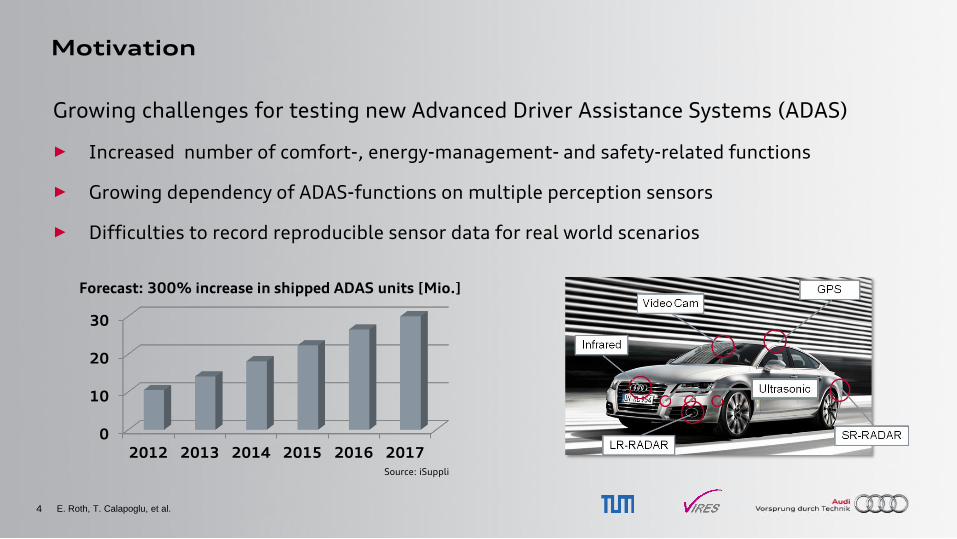
Motivation
Growing challenges for testing new Advanced Driver Assistance Systems (ADAS)
► Increased number of comfort-, energy-management- and safety-related functions
► Growing dependency of ADAS-functions on multiple perception sensors
► Difficulties to record reproducible sensor data for real world scenarios
E. Roth, T. Calapoglu, et al.
0
10
20
30
2012 2013 2014 2015 2016 2017
Forecast: 300% increase in shipped ADAS units [Mio.]
Source: iSuppli
5
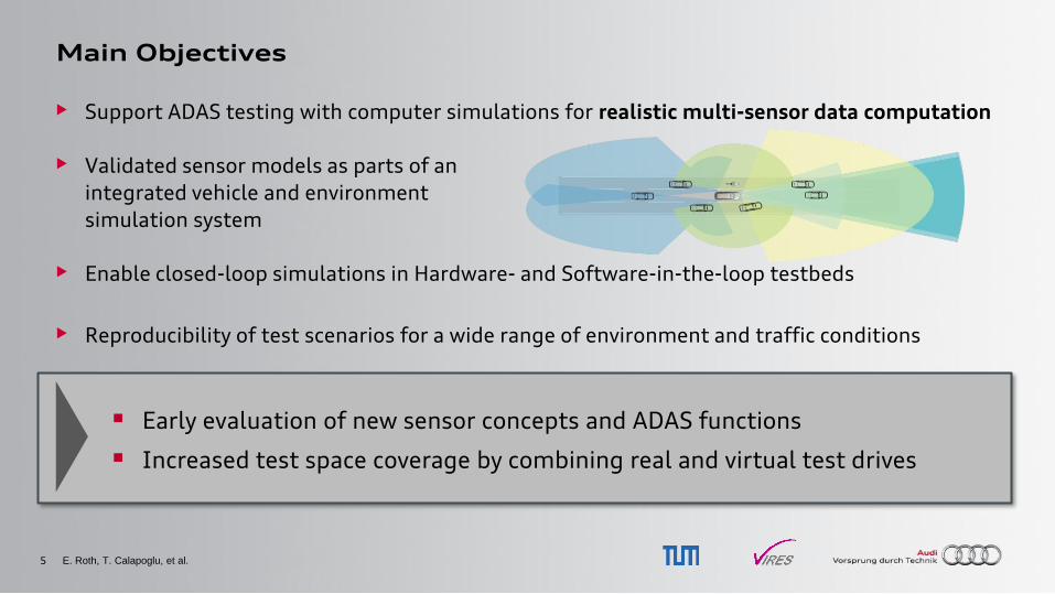
Main Objectives
• Support ADAS testing with computer simulations for realistic multi-sensor data computation
• Validated sensor models as parts of an
integrated vehicle and environment
simulation system
• Enable closed-loop simulations in Hardware- and Software-in-the-loop testbeds
• Reproducibility of test scenarios for a wide range of environment and traffic conditions
E. Roth, T. Calapoglu, et al.
Early evaluation of new sensor concepts and ADAS functions
Increased test space coverage by combining real and virtual test drives
6
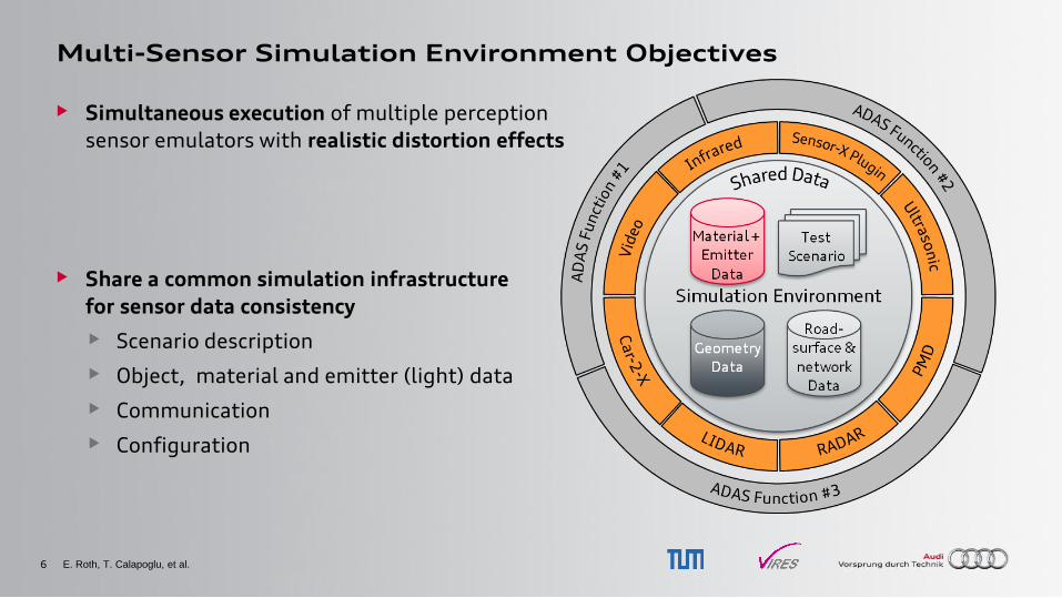
Multi-Sensor Simulation Environment Objectives
• Simultaneous execution of multiple perception
sensor emulators with realistic distortion effects
• Share a common simulation infrastructure
for sensor data consistency
• Scenario description
• Object, material and emitter (light) data
• Communication
• Configuration
E. Roth, T. Calapoglu, et al.
7
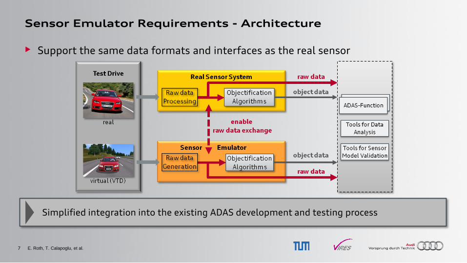
Sensor Emulator Requirements - Architecture
• Support the same data formats and interfaces as the real sensor
E. Roth, T. Calapoglu, et al.
Simplified integration into the existing ADAS development and testing process
8
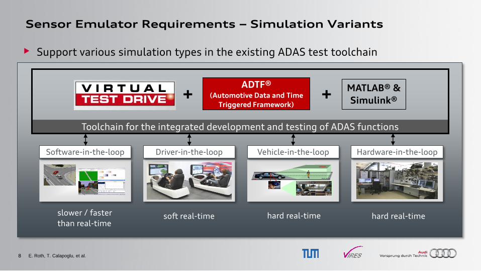
Sensor Emulator Requirements – Simulation Variants
• Support various simulation types in the existing ADAS test toolchain
E. Roth, T. Calapoglu, et al.
Toolchain for the integrated development and testing of ADAS functions
Hardware-in-the-loop Driver-in-the-loop Software-in-the-loop Vehicle-in-the-loop
virtuell
real Bock, EF-56
virtuell
real Bock, EF-56
ADTF® (Automotive Data and Time
Triggered Framework) + MATLAB® &
Simulink® +
slower / faster
than real-time hard real-time soft real-time hard real-time
9
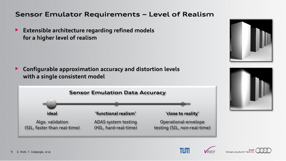
Sensor Emulator Requirements – Level of Realism
• Extensible architecture regarding refined models
for a higher level of realism
• Configurable approximation accuracy and distortion levels
with a single consistent model
E. Roth, T. Calapoglu, et al.
Sensor Emulation Data Accuracy
ideal
Algo. validation
(SIL, faster than real-time)
‘functional realism’
ADAS system testing
(HIL, hard-real-time)
‘close to reality’
Operational-envelope
testing (SIL, non-real-time)
10
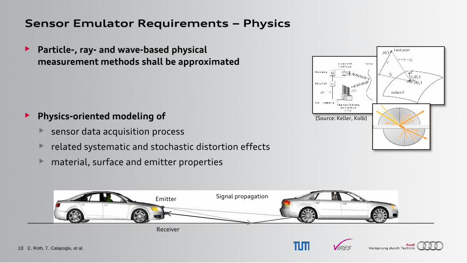
Sensor Emulator Requirements – Physics
• Particle-, ray- and wave-based physical
measurement methods shall be approximated
• Physics-oriented modeling of
• sensor data acquisition process
• related systematic and stochastic distortion effects
• material, surface and emitter properties
E. Roth, T. Calapoglu, et al.
Emitter
Receiver
Signal propagation
[Source: Keller, Kolb]
11
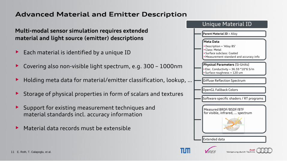
Advanced Material and Emitter Description
Multi-modal sensor simulation requires extended
material and light source (emitter) descriptions
• Each material is identified by a unique ID
• Covering also non-visible light spectrum, e.g. 300 – 1000nm
• Holding meta data for material/emitter classification, lookup, …
• Storage of physical properties in form of scalars and textures
• Support for existing measurement techniques and material standards incl. accuracy information
• Material data records must be extensible
E. Roth, T. Calapoglu, et al.
Unique Material ID
Parent Material ID = Alloy
Meta Data
•Description = „Alloy 85‟
•Class: Metal
•Surface subclass: Coated
•Measurement standard and accuracy info
Physical Parameters [Si-Units]
•Elec. Conductivity = 36.59 *10^6 S/m
•Surface roughness = 120 um
Diffuse Reflection Spectrum
OpenGL Fallback Colors
Software specific shaders / RT programs
Measured BRDF/BSDF/BTF for visible, infrared, … spectrum
Extended data
12
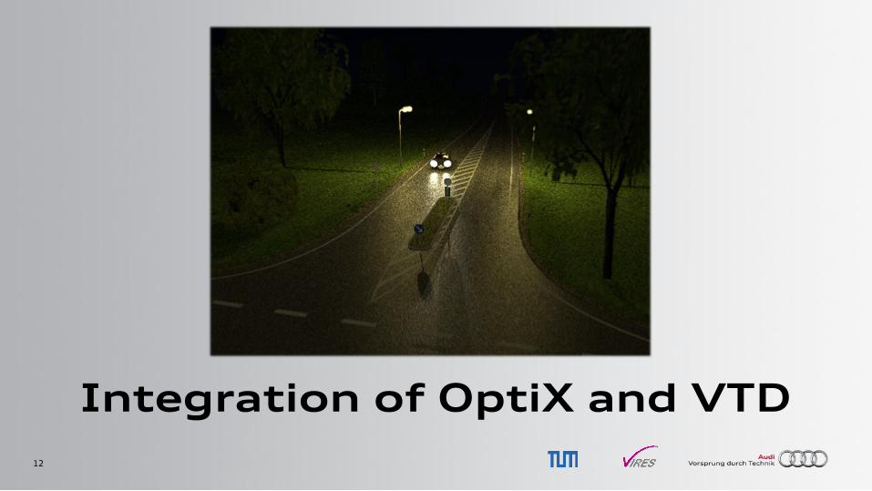
Integration of OptiX and VTD
13
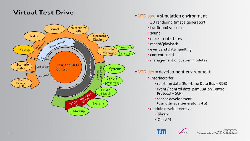
Virtual Test Drive • VTD core = simulation environment
• 3D rendering (image generator)
• traffic and scenario
• sound
• mockup interfaces
• record/playback
• event and data handling
• content creation
• management of custom modules
• VTD dev = development environment
• interfaces for
•run-time data (Run-time Data Bus – RDB)
•event / control data (Simulation Control Protocol – SCP)
•sensor development (using Image Generator v-IG)
• module development via
• library
• C++ API
Task and Data Control
Road Designer
ROD
Scenario Editor
Traffic
Sound 3D renderer v-IG
Mockup
Op
en I
nte
rfaces
3rd
Part
y
Com
ponents
Operator Station
Vehicle Dynamics
Configuration
Driver Model
Dynamics
Sensors
Module Manager
Systems
Mockup
Systems
14
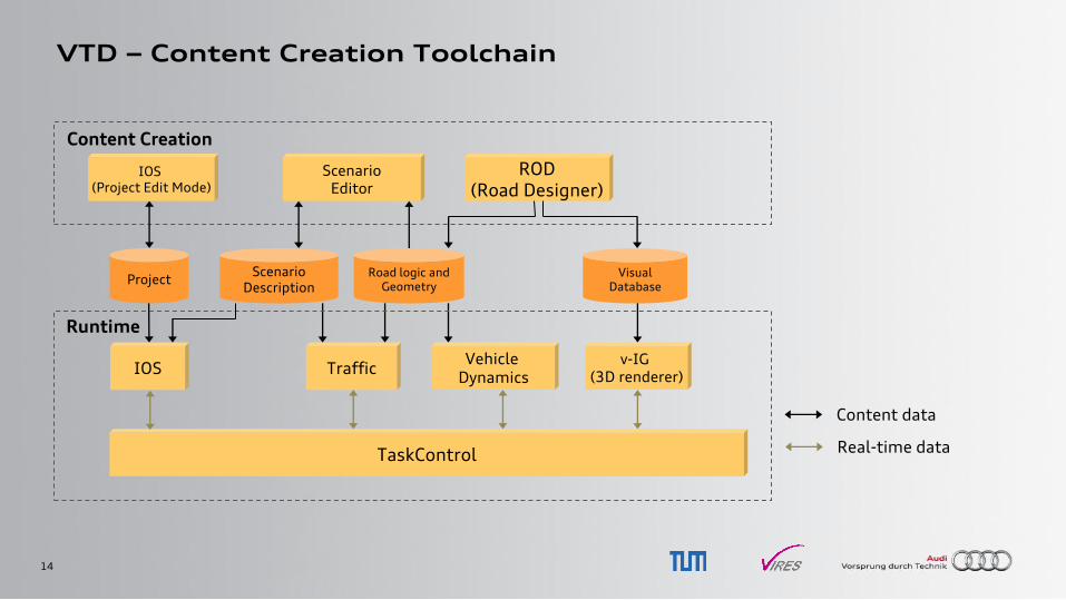
VTD – Content Creation Toolchain
IOS
TaskControl
Traffic v-IG
(3D renderer)
Visual Database
Road logic and Geometry
Vehicle Dynamics
Scenario Description
Project
ROD (Road Designer)
Content Creation
Scenario Editor
Runtime
IOS (Project Edit Mode)
Real-time data
Content data
15
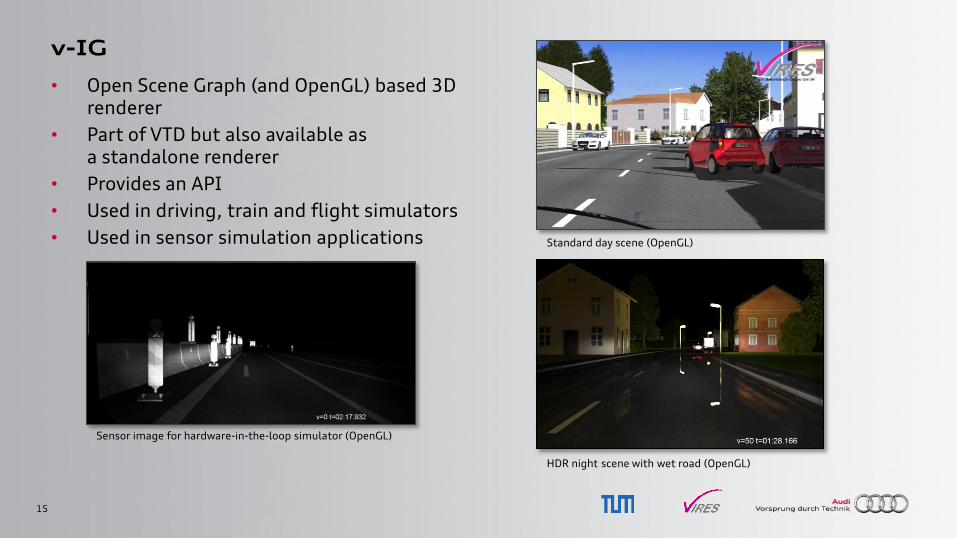
v-IG
• Open Scene Graph (and OpenGL) based 3D renderer
• Part of VTD but also available as a standalone renderer
• Provides an API
• Used in driving, train and flight simulators
• Used in sensor simulation applications
Sensor image for hardware-in-the-loop simulator (OpenGL)
Standard day scene (OpenGL)
HDR night scene with wet road (OpenGL)
16
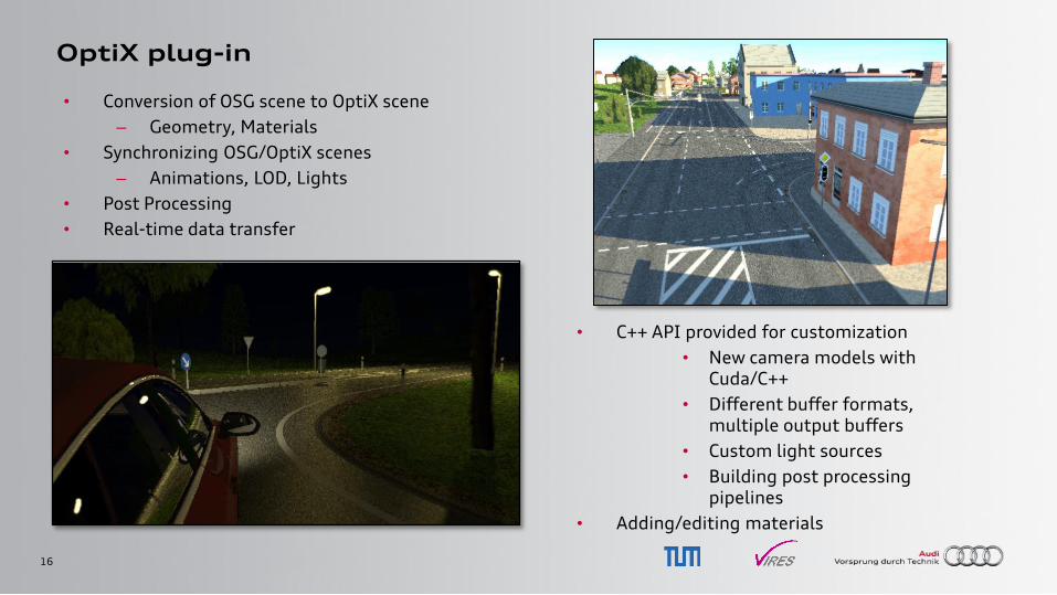
OptiX plug-in
• Conversion of OSG scene to OptiX scene
– Geometry, Materials
• Synchronizing OSG/OptiX scenes
– Animations, LOD, Lights
• Post Processing
• Real-time data transfer
• C++ API provided for customization
• New camera models with Cuda/C++
• Different buffer formats, multiple output buffers
• Custom light sources
• Building post processing pipelines
• Adding/editing materials
17
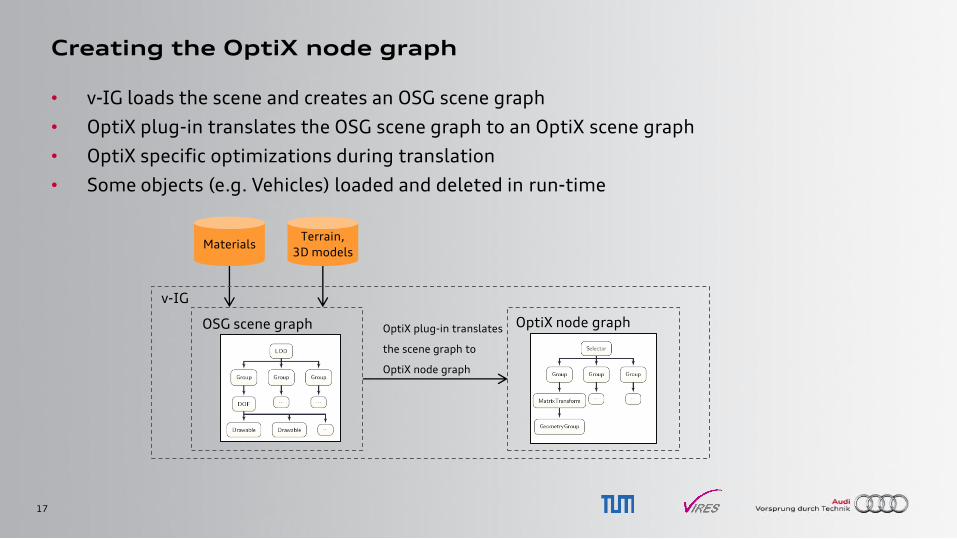
Creating the OptiX node graph
• v-IG loads the scene and creates an OSG scene graph
• OptiX plug-in translates the OSG scene graph to an OptiX scene graph
• OptiX specific optimizations during translation
• Some objects (e.g. Vehicles) loaded and deleted in run-time
Materials Terrain,
3D models
OSG scene graph OptiX node graph
v-IG
OptiX plug-in translates
the scene graph to
OptiX node graph
18
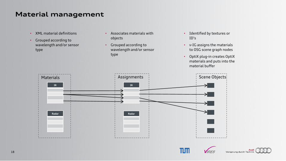
Material management
Assignments Materials
IR
Radar
IR
Radar
• Associates materials with
objects
• Grouped according to
wavelength and/or sensor
type
• XML material definitions
• Grouped according to
wavelength and/or sensor
type
Scene Objects
• Identified by textures or
ID„s
• v-IG assigns the materials
to OSG scene graph nodes
• OptiX plug-in creates OptiX
materials and puts into the
material buffer
19
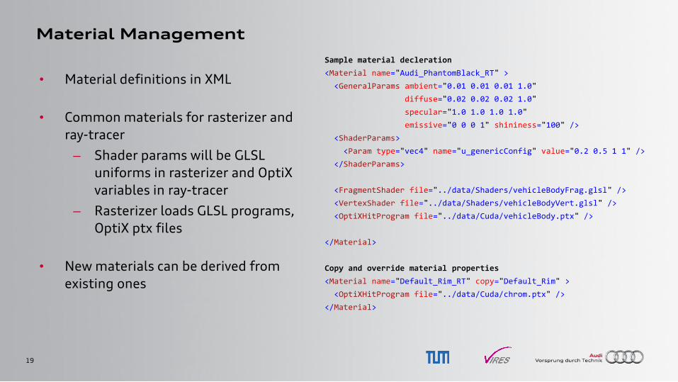
Material Management
• Material definitions in XML
• Common materials for rasterizer and
ray-tracer
– Shader params will be GLSL
uniforms in rasterizer and OptiX
variables in ray-tracer
– Rasterizer loads GLSL programs,
OptiX ptx files
• New materials can be derived from
existing ones
Sample material decleration
<Material name="Audi_PhantomBlack_RT" >
<GeneralParams ambient="0.01 0.01 0.01 1.0"
diffuse="0.02 0.02 0.02 1.0"
specular="1.0 1.0 1.0 1.0"
emissive="0 0 0 1" shininess="100" />
<ShaderParams>
<Param type="vec4" name="u_genericConfig" value="0.2 0.5 1 1" />
</ShaderParams>
<FragmentShader file="../data/Shaders/vehicleBodyFrag.glsl" />
<VertexShader file="../data/Shaders/vehicleBodyVert.glsl" />
<OptiXHitProgram file="../data/Cuda/vehicleBody.ptx" />
</Material>
Copy and override material properties
<Material name="Default_Rim_RT" copy="Default_Rim" >
<OptiXHitProgram file="../data/Cuda/chrom.ptx" />
</Material>
20
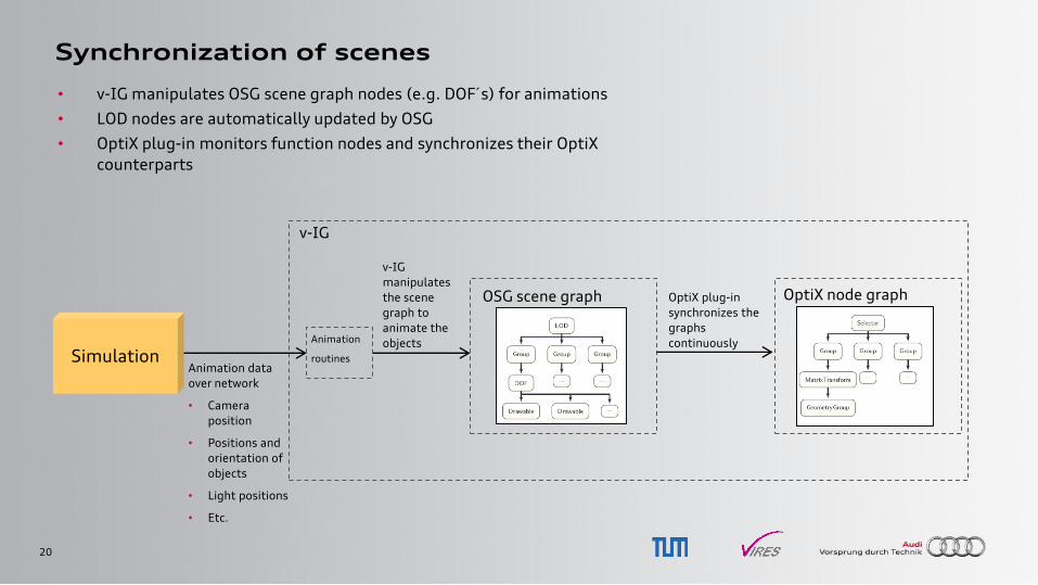
Synchronization of scenes
OSG scene graph OptiX node graph
v-IG
OptiX plug-in
synchronizes the
graphs
continuously
Animation data
over network
• Camera
position
• Positions and
orientation of
objects
• Light positions
• Etc.
v-IG
manipulates
the scene
graph to
animate the
objects Animation
routines
• v-IG manipulates OSG scene graph nodes (e.g. DOF´s) for animations
• LOD nodes are automatically updated by OSG
• OptiX plug-in monitors function nodes and synchronizes their OptiX
counterparts
Simulation

21
Lights and emitters
v-IG
OptiX plug-in
synchronizes the
lists continuously
Animation data
over network
• Positions and
orientation of
objects
• Light positions
Update lights that
are parts of
simulation entities
(e.g. Car
headlights) Object
animation
routines Simulation
v-IG Lights
Update lights that
are created and
managed by
external
applications
OptiX light buffer
Light
control
• v-IG creates and manages a list of lights
– Some lights are generated automatically with the information
stored in the terrain and models (car headlights, street lamps)
– Communication protocol allows for creating and controlling lights
externally
• OptiX plug-in synchronizes OptiX light buffer with v-IG lights
• Lights can represent any type of emitter
22
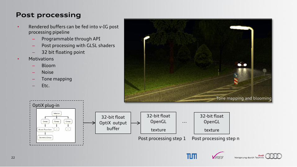
Post processing
• Rendered buffers can be fed into v-IG post processing pipeline
– Programmable through API
– Post processing with GLSL shaders
– 32 bit floating point
• Motivations
– Bloom
– Noise
– Tone mapping
– Etc.
OptiX plug-in
32-bit float
OptiX output
buffer
32-bit float
OpenGL
texture
...
Post processing step 1
32-bit float
OpenGL
texture
Post processing step n
Tone mapping and blooming
23
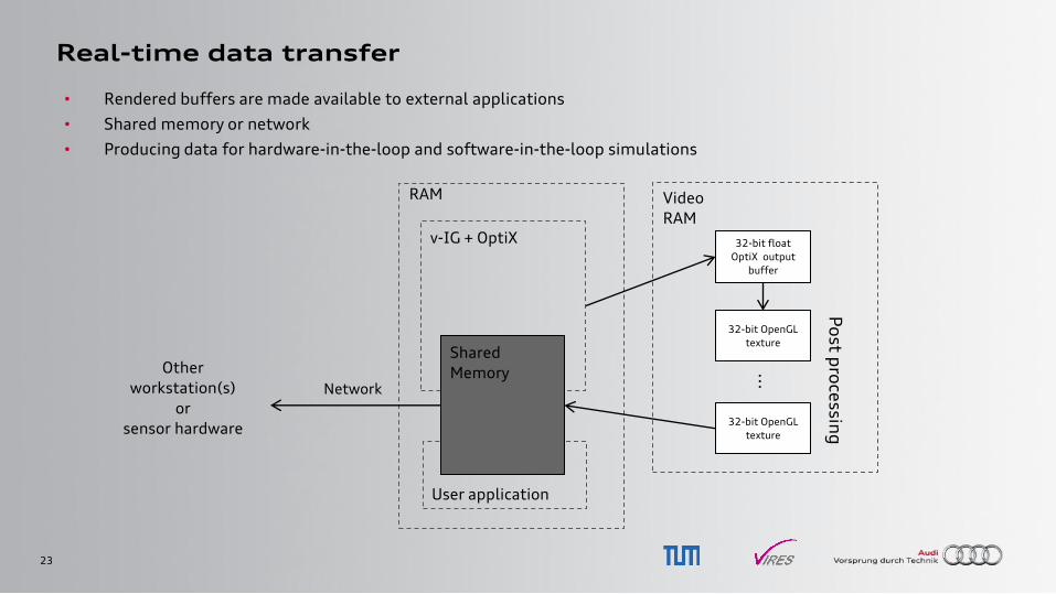
Real-time data transfer
• Rendered buffers are made available to external applications
• Shared memory or network
• Producing data for hardware-in-the-loop and software-in-the-loop simulations
RAM
v-IG + OptiX
Video
RAM
32-bit float
OptiX output
buffer
32-bit OpenGL
texture
32-bit OpenGL
texture
...
Po
st pro
cessin
g
User application
Shared
Memory Other
workstation(s)
or
sensor hardware
Network
24
Sensor Model Examples
using OptiX + VTD
25
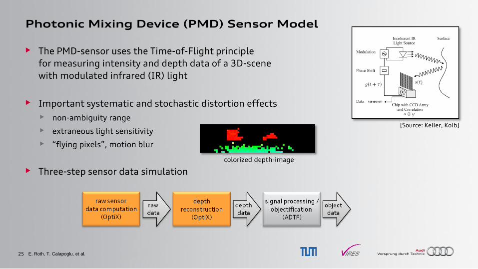
Photonic Mixing Device (PMD) Sensor Model
• The PMD-sensor uses the Time-of-Flight principle
for measuring intensity and depth data of a 3D-scene
with modulated infrared (IR) light
• Important systematic and stochastic distortion effects
• non-ambiguity range
• extraneous light sensitivity
• “flying pixels”, motion blur
• Three-step sensor data simulation
E. Roth, T. Calapoglu, et al.
[Source: Keller, Kolb]
colorized depth-image
26
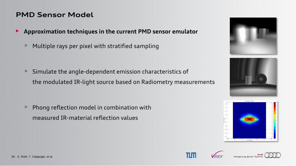
PMD Sensor Model
• Approximation techniques in the current PMD sensor emulator
• Multiple rays per pixel with stratified sampling
• Simulate the angle-dependent emission characteristics of
the modulated IR-light source based on Radiometry measurements
• Phong reflection model in combination with
measured IR-material reflection values
E. Roth, T. Calapoglu, et al.
27
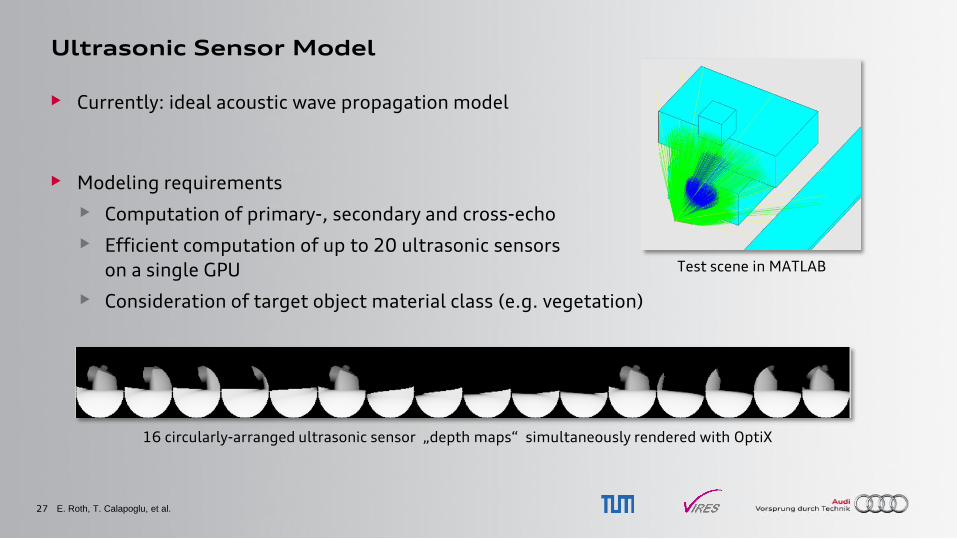
Ultrasonic Sensor Model
• Currently: ideal acoustic wave propagation model
• Modeling requirements
• Computation of primary-, secondary and cross-echo
• Efficient computation of up to 20 ultrasonic sensors
on a single GPU
• Consideration of target object material class (e.g. vegetation)
E. Roth, T. Calapoglu, et al.
16 circularly-arranged ultrasonic sensor „depth maps“ simultaneously rendered with OptiX
Test scene in MATLAB
28
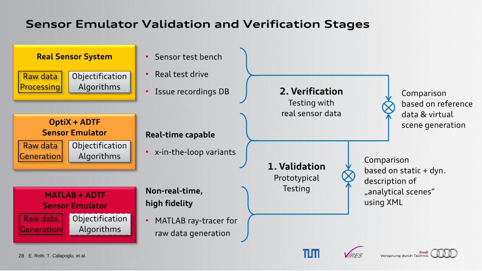
Sensor Emulator Validation and Verification Stages
Real Sensor System
Raw data
Processing
Objectification
Algorithms
Sensor test bench
Real test drive
Issue recordings DB
OptiX + ADTF
Sensor Emulator
Raw data
Generation
Objectification
Algorithms
MATLAB + ADTF
Sensor Emulator
Raw data
Generation
Objectification
Algorithms
Real-time capable
x-in-the-loop variants
Non-real-time,
high fidelity
MATLAB ray-tracer for
raw data generation
Comparison
based on static + dyn.
description of
„analytical scenes“
using XML
Comparison
based on reference
data & virtual
scene generation
E. Roth, T. Calapoglu, et al.
1. Validation Prototypical
Testing
2. Verification Testing with
real sensor data
29
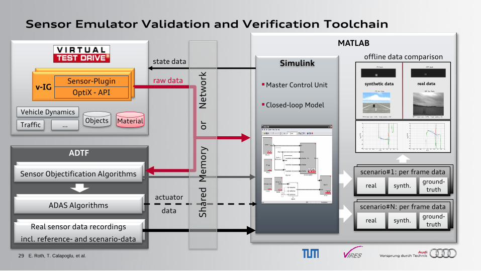
Sensor Emulator Validation and Verification Toolchain
MATLAB
ADTF
Sensor Objectification Algorithms Sensor Objectification Algorithms
ADAS Algorithms ADAS Algorithms
Real sensor data recordings
incl. reference- and scenario-data
real synth. ground-
truth
scenario#N: per frame data
Sensor-Plugin
OptiX - API v-IG
Vehicle Dynamics
Traffic Material Objects
…
Simulink
Master Control Unit
Closed-loop Model
Sh
are
d M
em
ory
or
N
etw
ork
state data
raw data
actuator
data
offline data comparison
real synth. ground-
truth
scenario#1: per frame data
E. Roth, T. Calapoglu, et al.
30
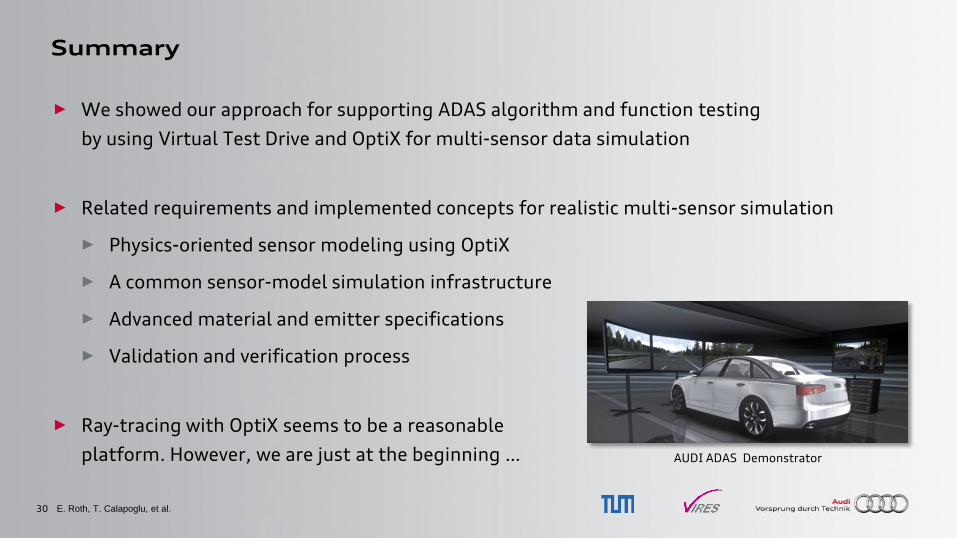
Summary
► We showed our approach for supporting ADAS algorithm and function testing
by using Virtual Test Drive and OptiX for multi-sensor data simulation
► Related requirements and implemented concepts for realistic multi-sensor simulation
► Physics-oriented sensor modeling using OptiX
► A common sensor-model simulation infrastructure
► Advanced material and emitter specifications
► Validation and verification process
► Ray-tracing with OptiX seems to be a reasonable
platform. However, we are just at the beginning …
E. Roth, T. Calapoglu, et al.
AUDI ADAS Demonstrator
31
Outlook
Challenges to be tackled in the future regarding …
► A standard for multi-spectral material and emitter specifications
► Simulation software independent description and identification scheme
► Physical property handling of materials and emitters, e.g. for wavelengths 300 – 1000nm
► Support for different measurement data formats and standards
► OptiX
► Support for large scenarios (1000x of objects, 100x materials, 10x sensor models, …)
► Improved multi-GPU scalability for 60 Hz and higher
► Improved OptiX debugging, profiling and optimization tools
E. Roth, T. Calapoglu, et al.
32
Vielen Dank.
E. Roth, T. Calapoglu, et al.
Get in touch with us, if you are
also using OptiX for sensor simulation!
Contact:
Erwin Roth, Technische Universität München
Tugkan Calapoglu, Vires Simulationstechnologie GmbH
Thank you very much.
33
BACKUP
E. Roth, T. Calapoglu, et al.
34
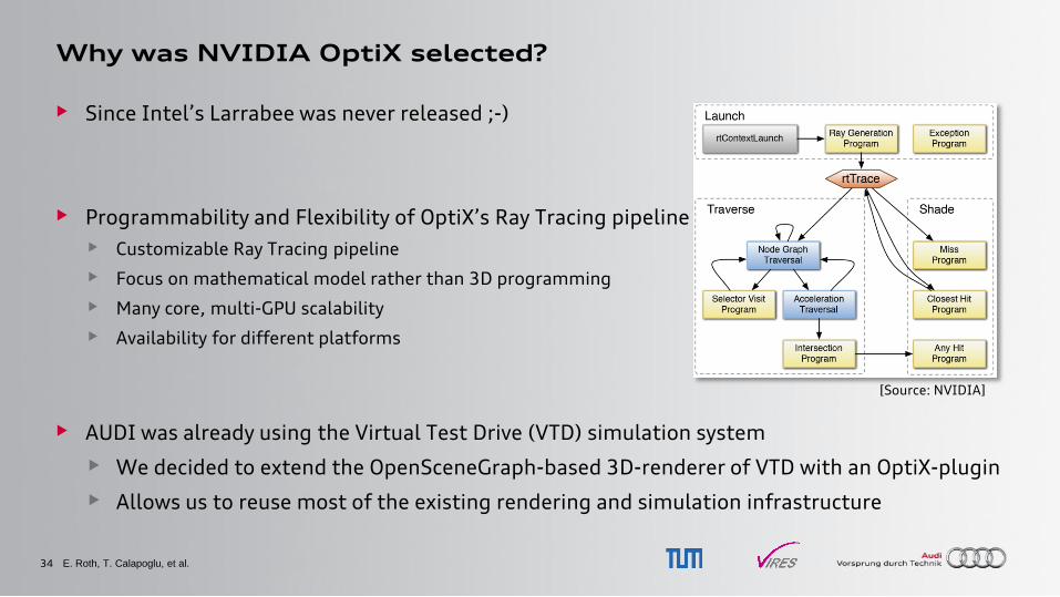
Why was NVIDIA OptiX selected?
• Since Intel‟s Larrabee was never released ;-)
• Programmability and Flexibility of OptiX‟s Ray Tracing pipeline
• Customizable Ray Tracing pipeline
• Focus on mathematical model rather than 3D programming
• Many core, multi-GPU scalability
• Availability for different platforms
• AUDI was already using the Virtual Test Drive (VTD) simulation system
• We decided to extend the OpenSceneGraph-based 3D-renderer of VTD with an OptiX-plugin
• Allows us to reuse most of the existing rendering and simulation infrastructure
E. Roth, T. Calapoglu, et al.
[Source: NVIDIA]
35
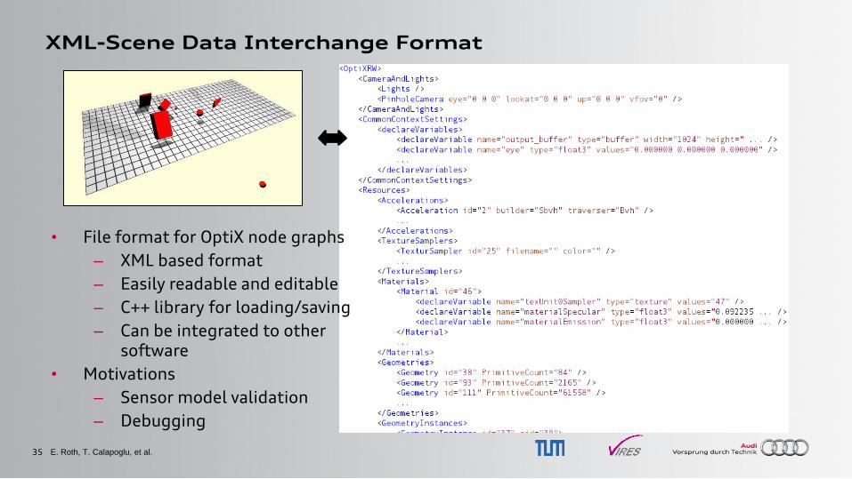
XML-Scene Data Interchange Format
• File format for OptiX node graphs
– XML based format
– Easily readable and editable
– C++ library for loading/saving
– Can be integrated to other software
• Motivations
– Sensor model validation
– Debugging
E. Roth, T. Calapoglu, et al.
36
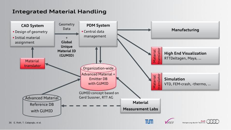
Integrated Material Handling
E. Roth, T. Calapoglu, et al.
CAD System
Design of geometry
Initial material
assignment
Manufacturing
Organization-wide
Advanced Material +
Emitter DB
with GUMID
Advanced Material
Reference DB
with GUMID
Material
Measurement Labs
Material
translator
PDM System
Central data
management
Geometry
Data
+
Global
Unique
Material ID
(GUMID) High End Visualization RTTDeltagen, Maya, …
Ma
teri
al
tra
nsl
ato
r
Ma
teri
al
tra
nsl
ato
r
Simulation VTD, FEM-crash, -thermo, …
GUMID concept based on
Gerd Sussner, RTT AG
37
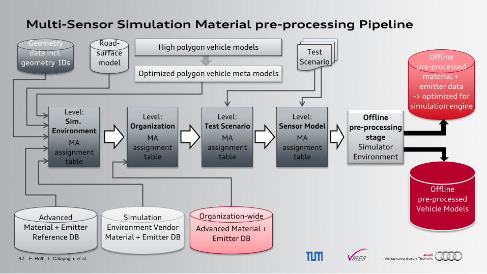
Multi-Sensor Simulation Material pre-processing Pipeline
Offline
pre-processed
material +
emitter data
-> optimized for
simulation engine
Test
Scenario
Simulation
Environment Vendor
Material + Emitter DB
Level:
Sim.
Environment
MA
assignment
table
Geometry
data incl.
geometry IDs
Road-
surface
model
Level:
Organization
MA
assignment
table
Organization-wide
Advanced Material +
Emitter DB
Level:
Test Scenario
MA
assignment
table
Level:
Sensor Model
MA
assignment
table
Optimized polygon vehicle meta models
High polygon vehicle models
Offline
pre-processed
Vehicle Models
Offline
pre-processing
stage
Simulator
Environment
Advanced
Material + Emitter
Reference DB
E. Roth, T. Calapoglu, et al.
38
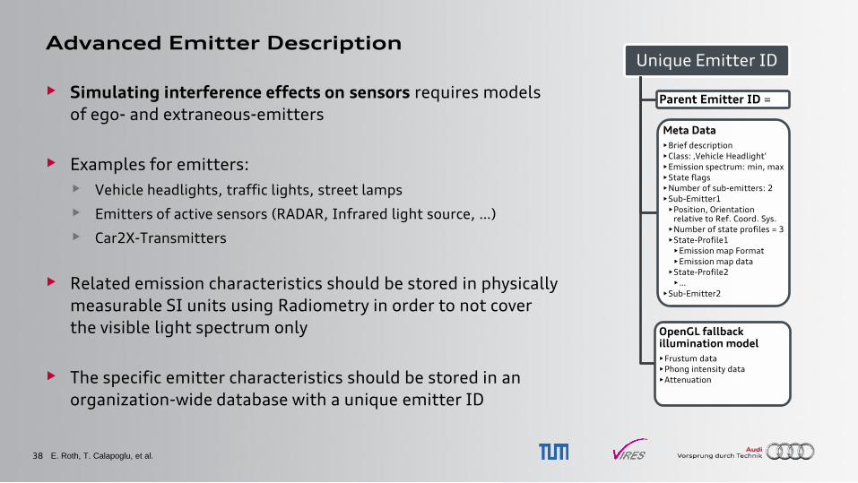
Advanced Emitter Description
• Simulating interference effects on sensors requires models
of ego- and extraneous-emitters
• Examples for emitters:
• Vehicle headlights, traffic lights, street lamps
• Emitters of active sensors (RADAR, Infrared light source, …)
• Car2X-Transmitters
• Related emission characteristics should be stored in physically
measurable SI units using Radiometry in order to not cover
the visible light spectrum only
• The specific emitter characteristics should be stored in an
organization-wide database with a unique emitter ID
E. Roth, T. Calapoglu, et al.
Unique Emitter ID
Meta Data
•Brief description
•Class: ‚Vehicle Headlight„
•Emission spectrum: min, max
•State flags
•Number of sub-emitters: 2
•Sub-Emitter1
•Position, Orientation relative to Ref. Coord. Sys.
•Number of state profiles = 3
•State-Profile1
•Emission map Format
•Emission map data
•State-Profile2
•…
•Sub-Emitter2
Parent Emitter ID =
OpenGL fallback illumination model
•Frustum data
•Phong intensity data
•Attenuation