Advanced Deaerator Control -...
80
750-236 12/2013 ADAC Advanced Deaerator Control Operation Manual
Transcript of Advanced Deaerator Control -...

750-23612/2013
ADAC Advanced Deaerator Control
Operation Manual

DO NOT OPERATE, SERVICE, OR REPAIR THIS EQUIPMENT UNLESS YOU FULLY UNDERSTAND ALL APPLICABLE SECTIONS OF THIS MANUAL.
DO NOT ALLOW OTHERS TO OPERATE, SERVICE, OR REPAIR THIS EQUIPMENT UNLESS THEY FULLY UNDERSTAND ALL APPLICABLE SECTIONS OF THIS MANUAL. FAILURE TO FOLLOW ALL APPLICABLE WARNINGS AND INSTRUCTIONS MAY RESULT IN SEVERE PERSONAL INJURY OR DEATH.
TO: Owners, Operators and/or Maintenance Personnel This operating manual presents information that will help to properly operate and care for the equipment. Study its contents carefully. The unit will provide good service and continued operation if proper operating and maintenance instructions are followed. No attempt should be made to operate the unit until the principles of operation and all of the components are thoroughly understood. Failure to follow all applicable instructions and warnings may result in severe personal injury or death.
It is the responsibility of the owner to provide safety training not only to his or her personnel, but to any contractor’s personnel who are servicing, repairing or operating the equipment.
Cleaver-Brooks equipment is designed and engineered to give long life and excellent service on the job. The electrical and mechanical devices supplied as part of the unit were chosen because of their known ability to perform; however, proper operating techniques and maintenance procedures must be followed at all times. Although these components afford a high degree of protection and safety, operation of equipment is not to be considered free from all dangers and hazards inherent in operating and maintaining this equipment.
Any "automatic" features included in the design do not relieve the attendant of any responsibility. Such features merely take over certain repetitive chores, allowing more time for the proper upkeep of equipment.
It is solely the operator’s responsibility to properly operate and maintain the equipment. No amount of written instructions can replace intelligent thinking and reasoning and this manual is not intended to relieve the operating personnel of the responsibility for proper operation. On the other hand, a thorough understanding of this manual is required before attempting to operate, maintain, service, or repair this equipment.
Operating controls will normally function for long periods of time and we have found that some operators become lax in their daily or monthly testing, assuming that normal operation will continue indefinitely. Malfunctions of controls lead to uneconomical operation and damage to the equipment. In most cases, these malfunctions can be traced directly to carelessness and deficiencies in testing and maintenance.
The operation of this equipment by the owner and the operating personnel must comply with all requirements or regulations of their insurance company and/or other authority having jurisdiction. In the event of any conflict or inconsistency between such requirements and the warnings or instructions contained herein, please contact Cleaver-Brooks before proceeding.

CONTENTSChapter 1 - General
Introduction . . . . . . . . . . . . . . . . . . . . . . . . . . . . . . . . . . . . . 1-2Single Tank System Description . . . . . . . . . . . . . . . . . . . . . . . 1-2
Standard Equipment . . . . . . . . . . . . . . . . . . . . . . . . . . . . 1-2Options . . . . . . . . . . . . . . . . . . . . . . . . . . . . . . . . . . . . . 1-3
Two Tank System Description . . . . . . . . . . . . . . . . . . . . . . . . . 1-4Standard Equipment . . . . . . . . . . . . . . . . . . . . . . . . . . . . 1-4Options . . . . . . . . . . . . . . . . . . . . . . . . . . . . . . . . . . . . . 1-5
Specifications . . . . . . . . . . . . . . . . . . . . . . . . . . . . . . . . . . . . 1-6
Chapter 2 - System ComponentsComponents . . . . . . . . . . . . . . . . . . . . . . . . . . . . . . . . . . . . . 2-2
Controller . . . . . . . . . . . . . . . . . . . . . . . . . . . . . . . . . . . . 2-2Operator Interface . . . . . . . . . . . . . . . . . . . . . . . . . . . . . . 2-4Ethernet Communications . . . . . . . . . . . . . . . . . . . . . . . . 2-4Sensor Inputs . . . . . . . . . . . . . . . . . . . . . . . . . . . . . . . . . 2-4
Optional Accessories . . . . . . . . . . . . . . . . . . . . . . . . . . . . . . . 2-5Sensors . . . . . . . . . . . . . . . . . . . . . . . . . . . . . . . . . . . . . 2-5Variable Speed Drives for Pumps . . . . . . . . . . . . . . . . . . . 2-5Recirculation Valve Control . . . . . . . . . . . . . . . . . . . . . . . 2-5Magnetic Level Transmitter . . . . . . . . . . . . . . . . . . . . . . . 2-5Differential Pressure Level Transmitter . . . . . . . . . . . . . . . . 2-6
Chapter 3 - CommissioningHMI Navigation . . . . . . . . . . . . . . . . . . . . . . . . . . . . . . . . . . . . . . . . 3-2Entering values on the HMI screens . . . . . . . . . . . . . . . . . . . . . . . . . . 3-3Main Menu . . . . . . . . . . . . . . . . . . . . . . . . . . . . . . . . . . . . . . . . . . . 3-3Configuring I/O Modules . . . . . . . . . . . . . . . . . . . . . . . . . . . . . . . . . . 3-4DA Tank Options . . . . . . . . . . . . . . . . . . . . . . . . . . . . . . . . . . . . . . . 3-5Surge Tank Options . . . . . . . . . . . . . . . . . . . . . . . . . . . . . . . . . . . . . 3-6Analog Input Configuration . . . . . . . . . . . . . . . . . . . . . . . . . . . . . . . . 3-7Feed Pump Configuration . . . . . . . . . . . . . . . . . . . . . . . . . . . . . . . . . 3-8Transfer Pump Configuration . . . . . . . . . . . . . . . . . . . . . . . . . . . . . . 3-10Boiler Feedwater Header Pressure Control . . . . . . . . . . . . . . . . . . . . 3-10Transfer Header Pressure Control . . . . . . . . . . . . . . . . . . . . . . . . . . . 3-11DA Primary Makeup Valve Control . . . . . . . . . . . . . . . . . . . . . . . . . . 3-12DA Secondary Makeup Valve Control . . . . . . . . . . . . . . . . . . . . . . . . 3-13Surge Primary Makeup Valve Control . . . . . . . . . . . . . . . . . . . . . . . . 3-13Surge Secondary Makeup Valve Control . . . . . . . . . . . . . . . . . . . . . . 3-13DA Tank PRV Steam Valve Control . . . . . . . . . . . . . . . . . . . . . . . . . . 3-13Chemical Feed Configuration . . . . . . . . . . . . . . . . . . . . . . . . . . . . . 3-14Ethernet Configuration . . . . . . . . . . . . . . . . . . . . . . . . . . . . . . . . . . 3-15Display Configuration . . . . . . . . . . . . . . . . . . . . . . . . . . . . . . . . . . . 3-16

Chapter 4 - OperationSystem Control/Operation . . . . . . . . . . . . . . . . . . . . . . . . . . . . 4-2
Screen Select . . . . . . . . . . . . . . . . . . . . . . . . . . . . . . . . . 4-2DA Tank Overview . . . . . . . . . . . . . . . . . . . . . . . . . . . . . . 4-2Surge Tank Overview . . . . . . . . . . . . . . . . . . . . . . . . . . . . 4-3Duo Tank Overview. . . . . . . . . . . . . . . . . . . . . . . . . . . . . . 4-4Feed Pump Control . . . . . . . . . . . . . . . . . . . . . . . . . . . . . 4-4Transfer Pump Control . . . . . . . . . . . . . . . . . . . . . . . . . . . 4-6
Alarms . . . . . . . . . . . . . . . . . . . . . . . . . . . . . . . . . . . . . . . . . 4-6Alarm Banner . . . . . . . . . . . . . . . . . . . . . . . . . . . . . . . . . 4-6Alarm History. . . . . . . . . . . . . . . . . . . . . . . . . . . . . . . . . . 4-7
Chapter 5 - Input/Output ListsSingle Tank PLC I/O Layout. . . . . . . . . . . . . . . . . . . . . . . . . . . . 5-2Two Tank PLC I/O Layout . . . . . . . . . . . . . . . . . . . . . . . . . . . . . 5-5
Chapter 6 - PartsParts List . . . . . . . . . . . . . . . . . . . . . . . . . . . . . . . . . . . . . . . . 6-2
Appendix - Supporting Documents/Reference DrawingsMagnetic Level Control Sizing Chart . . . . . . . . . . . . . . . . . . . . . A-2Magnetic Level Control Installation Diagram . . . . . . . . . . . . . . . . A-4DA Level Differential Pressure Transmitter Calibration . . . . . . . . . A-5Differential Pressure Level Control . . . . . . . . . . . . . . . . . . . . . . . A-6Differential Pressure Level Control/DA Tank Pressure Control . . . . . A-7Single Tank I/O Card Layout . . . . . . . . . . . . . . . . . . . . . . . . . . . A-9Dual Tank I/O Card Layout . . . . . . . . . . . . . . . . . . . . . . . . . . . A-10Wiring Diagram . . . . . . . . . . . . . . . . . . . . . . . . . . . . . . . . . . A-11Control Panel Layout . . . . . . . . . . . . . . . . . . . . . . . . . . . . . . . A-13DA Tank . . . . . . . . . . . . . . . . . . . . . . . . . . . . . . . . . . . . . . . A-14Surge Tank . . . . . . . . . . . . . . . . . . . . . . . . . . . . . . . . . . . . . . A-15Duo-Tank . . . . . . . . . . . . . . . . . . . . . . . . . . . . . . . . . . . . . . . A-16Alarm Piping . . . . . . . . . . . . . . . . . . . . . . . . . . . . . . . . . . . . A-17Make-Up Valve . . . . . . . . . . . . . . . . . . . . . . . . . . . . . . . . . . . A-18Gauge Glass . . . . . . . . . . . . . . . . . . . . . . . . . . . . . . . . . . . . . A-21Pressure Reducing Valve . . . . . . . . . . . . . . . . . . . . . . . . . . . . A-22Discharge Manifold . . . . . . . . . . . . . . . . . . . . . . . . . . . . . . . . A-23Recirculation Piping . . . . . . . . . . . . . . . . . . . . . . . . . . . . . . . A-24

www.cleaverbrooks.com
Chapter 1General
Introduction . . . . . . . . . . . . . . . . . . . . . . . . . . . . . . . . . . . . . . 1-2Single Tank System Description . . . . . . . . . . . . . . . . . . . . . . . 1-2
Standard Equipment . . . . . . . . . . . . . . . . . . . . . . . . . . . . 1-2Options . . . . . . . . . . . . . . . . . . . . . . . . . . . . . . . . . . . . . 1-3
Two Tank System Description . . . . . . . . . . . . . . . . . . . . . . . . . 1-4Standard Equipment . . . . . . . . . . . . . . . . . . . . . . . . . . . . 1-4Options . . . . . . . . . . . . . . . . . . . . . . . . . . . . . . . . . . . . . 1-5
Specifications . . . . . . . . . . . . . . . . . . . . . . . . . . . . . . . . . . . . . 1-6
Chapter 1 — General
1.1-IntroductionThe Cleaver-Brooks ADAC is an exclusive Deaerator and/or SurgeTank Management and Control System specifically designed tointegrate the functions of a Programmable Controller with otheroperating and ancillary controls. The Programmable Controller(PLC) is a modular design providing flexibility for expansion witheasily serviceable components. The ADAC system incorporates auser-friendly, graphical touch screen Human Machine Interface thatdisplays tank parameters, fault annunciation and alarm history, aswell as providing access to system configuration and controlfunctions. The system provides a complete tank level, tankpressure, and pump control solution.
In addition to installation on new Deaerators and Surge tanks, theADAC can be added as a retrofit to existing tanks. Call your localauthorized Cleaver-Brooks representative for details.
1.2-Single Tank System Description A single tank system can control up to 6 pumps, all of which canbe run by contactors, combination starters, soft starters, or VariableSpeed Drives. All pumps on a tank must utilize the same type ofstarter/drive.
Pumps on a common header can be alternated on a customerdefined schedule and be set up in a customer defined lead lagformat.
When lead lag operation is in use, a pressure transmitter mountedin the common header sends a signal to the PLC. The customer setsthe pressure point via the touch screen. If the first pump cannotachieve that set point, the PLC will start a second pump and so on.If the pressure rises above the set point, the PLC will shed the lastpump and so on.
Pumps on a “one pump per boiler” installation can be controlled bya contact closure on the boiler. Variable Speed Drives cannot beused in a one pump per boiler configuration where each pump ishard piped to individual boilers. VSDs are only available on commonpump discharge header configurations.
Standard system is capable of using discrete level alarm switches(such as the McDonnell Miller 63 or 64) for fixed level alarms, or alevel transmitter which can be configured from the touch screen.
OPC compliant Ethernet IP communications are included asstandard. This feature can be used to connect the ADAC system toa boiler Master Panel or customer BAS.
A. Standard Equipment
PLC based control system for a single tank includes processor, PLCPower supply, I/O cards, 7" color touch screen, and NEMA 4 controlpanel. Programming and I/O are provided for the following:
1-2 Part No. 750-236

Chapter 1 — General
• 1-6 pumps using contactors, soft starters or combination starters; inputs and outputs which include Hand-Off-Auto Selector Switches, a pump motor running input, a pump motor overload or fault input, and pump run output.
• Low Water pump cut off• Audible Alarm output• Stack Light outputs and light (Green for all systems normal,
Yellow for non-critical alarms such as High Water, Red for critical alarm such as Pump Failure)
• Recirc Bypass output • Chemical Feed Relay output• Boiler 1-6 feed water required inputs for one pump per boiler
configuration• Analog Tank Pressure Input • Analog Tank Temperature Input • Analog Tank Level Input • Analog Discharge Header Pressure Input
B. Options
Programming and I/O cards for the following are optional (eachoption requires the preceding ones):
Option 1
• Feedwater Make up Valve Analog Output• PRV Analog Output
Option 2
• 1-6 Pump Proving Flow Switch Inputs
Option 3
• Single tank system emergency Make up Valve
Option 4
• 1-3 VSD driven pumps I/O• 1 customer configured analog input
Option 5
• 4-6 VSD driven pumps I/O• Overflow valve control
Option 6
• 3-6 BF pump (1 pump per boiler) feedwater pressure analog inputs
Note: Each ADAC programming option requires the correspondinghardware (drives, valves, transmitters, switches, etc.)
Part No. 750-236 1-3
Chapter 1 — General
1.3-Two Tank System Description Two Tank systems can control up to 6 boiler feed pumps and 3transfer pumps, all of which can be run by contactors, combinationstarters, soft starters, or Variable Speed Drives. Method selectedmust be the same for all pumps on a tank, but tank 1 method canbe different from tank 2. For example, Tank 1 may use variablespeed drives, but tank 2 may use contactors.
Pumps on a common header can be alternated on a customerdefined schedule and be set up in a customer defined lead lagformat.
When lead lag operation is in use, a pressure transmitter mountedin the common header sends a signal to the PLC. The customer setsthe pressure point via the touch screen. If the first pump cannotachieve that set point, the PLC will start a second pump and so on.If the pressure rises above the set point, the PLC will shed the lastpump and so on.
Pumps on a “one pump per boiler” installation can be controlled bythe boiler. Variable Speed Drives cannot be used in a one pump perboiler configuration where each pump is hard piped to individualboilers. VSDs are only available on common pump discharge headerconfigurations.
Standard system is capable of using discrete level alarm switches(such as the McDonnell Miller 63 or 64) for fixed level alarms, or alevel transmitter which can be configured from the touch screen.
Level control can be an independent mechanical system, or by usingthe above mentioned transmitter, control an electrical or I/P make-up valve.
Tank Pressure is monitored by a transmitter in steam space. PRVcan be an independent mechanical system or an electrical or I/Ppressure reducing valve. The second tank will be treated as anatmospheric pressure tank and will not have a tank pressure sensor.
A. Standard Equipment
10 inch color touch screen is standard.
A three module stack light is standard with a light for each mode.Green for normal, Yellow for non critical alarms Red for criticalalarms. An audible alarm is standard, either a bell, horn orelectronic sounder
PLC based control system for a two tank starts with and includesprocessor, PLC Power supply, I/O cards, 10" color touch screen, andNema 4 control panel to provide the following functions
Level control can be an independent mechanical system, or by usingthe above mentioned transmitter, control an electrical or I/P make-up valve.
Tank Pressure is monitored by a transmitter in steam space. PRVcan be an independent mechanical system or an electrical or I/Ppressure reducing valve.
1-4 Part No. 750-236

Chapter 1 — General
Communication options include OPC compliant Ethernet IP toBoiler master panel or customer BAS.
PLC based control system for a two tank starts with and includesprocessor, PLC Power supply, I/O cards, 10" color touch screen, andNEMA 4 control panel. Programming and I/O provided for thefollowing:
• 1-6 pumps on the first tank, 1-3 pumps on the second tank using contactors, soft starters or combination starters; inputs and outputs which include Hand-Off-Auto Selector Switches, a pump motor running input, a pump motor overload or fault input, and pump run output.
• Low Water pump cut off on both tanks• Audible Alarm output• Stack Light outputs and light (Green for all systems normal,
Yellow for non-critical alarm such as High Water, Red for critical alarms such as Pump Failure)
• Recirc Bypass output on Tank One Only• Chemical Feed Relay output on both tanks• Boiler 1-6 feed water required inputs• Analog Tank Pressure Input on Tank One only• Analog Tank Temperature Input and transmitter on both tanks• Analog Tank Level Input on both tanks• Analog Discharge Header Pressure Input on both tanks using
common headers• 1 customer configured Analog Input• 1-6 Pump Proving Flow Switch Inputs
B. Options
Programming and I/O cards for the following are optional (eachoption requires the preceding ones):
Option 1
• Feedwater Make up Valve Analog Output for both tanks
Option 2
• PRV Analog Output• Emergency Make up Valve Analog Output for tank 1.
Option 3
• Emergency Make up Valve Analog Output for tank 2.
Option 4
• 1-3 VSD driven pumps I/O on tank one• 1 VSD driven pump I/O on tank 2
Part No. 750-236 1-5
Chapter 1 — General
Option 5
• 4-6 VSD driven pumps I/O on tank one• 2-3 VSD driven pumps I/O on tank two• 2-6 BF pump (1 pump per boiler) feedwater pressure analog
inputs
Note: Each ADAC programming option requires the correspondinghardware (drives, valves, transmitters, switches, etc.)
1.4-Specifications
PowerPower Supply Voltage 120 VAC (102 VAC - 132 VAC)Power Supply Frequency 50 or 60 HzMaximum Total Connected Load 500 VAFusingController Power Supply 3.15AAnalog Power Supply 2ATouch Screen HMI 2AEnvironmentalAmbient Operating Temperature Limits 32° to 130°F.Humidity 85% RH continuous, non-condensingVibration Continuous to 0.5 G
1-6 Part No. 750-236

www.cleaverbrooks.com
Chapter 2System Components
Components . . . . . . . . . . . . . . . . . . . . . . . . . . . . . . . . . . . . . . 2-2Controller . . . . . . . . . . . . . . . . . . . . . . . . . . . . . . . . . . . . 2-2Operator Interface. . . . . . . . . . . . . . . . . . . . . . . . . . . . . . . 2-4Ethernet Communications . . . . . . . . . . . . . . . . . . . . . . . . . 2-4Sensor Inputs . . . . . . . . . . . . . . . . . . . . . . . . . . . . . . . . . 2-4
Optional Accessories . . . . . . . . . . . . . . . . . . . . . . . . . . . . . . . 2-5Sensors . . . . . . . . . . . . . . . . . . . . . . . . . . . . . . . . . . . . . 2-5Variable Speed Drives for Pumps . . . . . . . . . . . . . . . . . . . . 2-5Recirculation Valve Control . . . . . . . . . . . . . . . . . . . . . . . . 2-5Magnetic Level Transmitter . . . . . . . . . . . . . . . . . . . . . . . . 2-5Differential Pressure Level Transmitter . . . . . . . . . . . . . . . . 2-6
Chapter 2 — System Components
2.1-ComponentsThe ADAC control system consists primarily of a ProgrammableController (PLC), touch screen Human Machine Interface (HMI),24VDC power supplies, stack light, and various relays. Optionalcomponents could include an EtherNet switch.
The ADAC controller is factory pre-programmed to work with mostCleaver-Brooks deaerator and surge tank systems, yet allows easyconfiguration for specific options. The controller program logic ispassword secured, ensuring tamper-proof operation. The touchscreen HMI provides user-friendly access to pump and level controlfunctions, diagnostics and alarm histories, and any connectedoperating parameters.
A. Controller
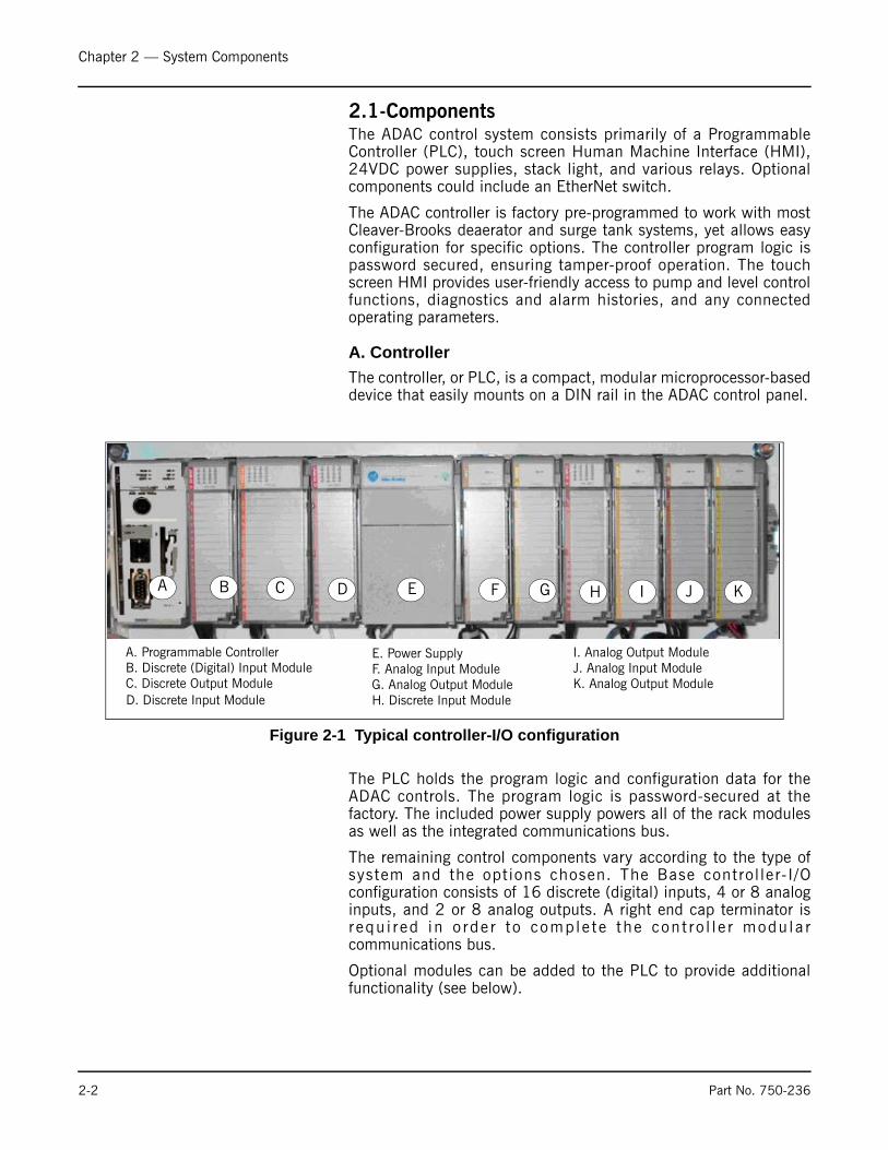
The controller, or PLC, is a compact, modular microprocessor-baseddevice that easily mounts on a DIN rail in the ADAC control panel.
The PLC holds the program logic and configuration data for theADAC controls. The program logic is password-secured at thefactory. The included power supply powers all of the rack modulesas well as the integrated communications bus.
The remaining control components vary according to the type ofsystem and the options chosen. The Base control ler- I /Oconfiguration consists of 16 discrete (digital) inputs, 4 or 8 analoginputs, and 2 or 8 analog outputs. A right end cap terminator isr equ i r ed in o rde r t o comp le te the con t ro l l e r modu la rcommunications bus.
Optional modules can be added to the PLC to provide additionalfunctionality (see below).
Figure 2-1 Typical controller-I/O configuration
A B C D E F G H
A. Programmable ControllerB. Discrete (Digital) Input ModuleC. Discrete Output ModuleD. Discrete Input Module
E. Power SupplyF. Analog Input ModuleG. Analog Output ModuleH. Discrete Input Module
I J K
I. Analog Output ModuleJ. Analog Input ModuleK. Analog Output Module
2-2 Part No. 750-236

Chapter 2 — System Components
Single Tank PLC Layout (also see Chapter 5, Input/Output Lists)
Base System
1. Processor (Slot 0) 2. Discrete Input Module (16 inputs) (Slot 1) 3. Discrete Output Module (16 outputs) (Slot 2)4. Discrete Input Module (16 inputs) (Slot 3) 5. Power Supply 6. Analog Input Module (4 Ch.)(Slot 4)
Optional Cards
7. Analog Output Module (2 Ch.)(Slot 5) 8. Discrete Input Module (16 inputs) (Slot 6) 9. Analog Output Module (2 Ch.)(Slot 7)10. Analog Input Module (4 Ch.)(Slot 8) 11. Analog Output Module (2 Ch.)(Slot 9)
Second Rack
12. Rack Expansion Kit13. Power Supply14. Analog Output Module (2 Ch.)(Slot 10) 15. Analog Input Module (4 Ch.)(Slot 11)16. Analog Output Module (2 Ch.)(Slot 12) 17. Analog Input Module (4 Ch.)(Slot 13)
Two Tank PLC Layout (also see Chapter 5, Input/Output Lists)
Base System
1. Processor (Slot 0) 2. Discrete Input Module (16 inputs) (Slot 1) 3. Discrete Output Module (16 outputs) (Slot 2)4. Discrete Input Module (16 inputs) (Slot 3) 5. Power Supply 6. Discrete Input Module (16 inputs) (Slot 4) 7. Analog Input Module (4 Ch.)(Slot 5)8. Analog Input Module (4 Ch.)(Slot 6)
Optional Cards
9. Analog Output Module (2 Ch.)(Slot 7) 10. Analog Output Module (2 Ch.)(Slot 8) 11. Analog Output Module (2 Ch.)(Slot 9)
Second Rack
12. Rack Expansion Kit13. Power Supply14. Analog Input Module (4 Ch.)(Slot 10)15. Analog Output Module (8 Ch.)(Slot 11) 16. Analog Input Module (4 Ch.)(Slot 12)17. Analog Input Module (8 Ch.)(Slot 13)
Part No. 750-236 2-3

Chapter 2 — System Components
B. Operator Interface
Single tank systems use a 7” touch screen HMI, which providesuser-friendly access to boiler control information and functions in abacklit color display. The HMI not only displays numerous ADACparameters at a glance, but in addition provides easy menunavigation for configuring control functions and troubleshootingalarms. A 10” touch screen is standard for two tank systems.
The HMI communicates with the PLC using an Ethernet connection.
C. Ethernet Communications
An Ethernet/IP port connects the ADAC controller to an Ethernetnetwork. The ADAC utilizes OPC compliant Ethernet/IP for severalcommunication functions:
• Connection between PLC and operator interface
• Connecting the ADAC system to an existing infrastructure, e.g. plant Local Area Network (LAN)
• Integration with a Building/Plant Automation System (BAS)
• Remote monitoring of the system via customer Wide Area Network (WAN) or via Internet
Ethernet/IP is also used for certain control functions. The CB HawkICS Boiler Room Network connects individual boiler controllers andthe ADAC with the Cleaver-Brooks Hawk ICS Master Boiler RoomController. The Boiler Room Network provides a single BAS interfacefor multiple boilers and one ADAC system. Additional boiler roomcontrol functions can also be incorporated into the Master controller.
D. Sensor Inputs
• Optional Steam Pressure Transmitter for DA tanks only (Fig. 2-3); mounted in steam space. This transmitter provides a sensor input to the ADAC controller. It transmits a 4-20mA process variable signal to the controller for the purpose of displaying pressure inside the tank or to provide a process value for optional PRV control.
• Optional Hot Water Temperature Transmitter (Fig. 2-4); one per tank. This transmitter provides a sensor input to the ADAC controller. The 4-20mA signal is used to display water temperature in the tank.
Figure 2-2
Figure 2-3
Figure 2-4
2-4 Part No. 750-236

Chapter 2 — System Components
2.2-Optional AccessoriesA. Sensors• Water Level, 4-20mA signal, one per tank (Fig. 2-5).
•Header Pressure Transmitter, 4-20 mA signal (used for pump lead/lag and alternation), one per tank for common headers (Fig. 2-6). Required on common headers.
B. Variable Speed Drives for PumpsAn optional Variable Speed Drive (VSD) controls the speed of thepump motor for enhanced pressure/flow control and reducedelectrical energy consumption.
Drives are NEMA 1 and are supplied with line reactors.
C. Recirculation Valve ControlThis option (standard on single tank systems) allows the ADACsystem to close off the recirculation piping, sending all of the pumpflow out to the boiler. When the system detects sufficient flow toprotect the pump, the valve closes. When demand drops, the valveopens, allowing flow back to the tank and protecting the pump.
D. Magnetic Level TransmitterThe level transmitter is made up of four components:
• Stainless steel chamber with 2 process connections
• Level indicator consisting of magnetically interlocked flags in a plastic housing strapped to the chamber.
Figure 2-5
Figure 2-6
Figure 2-7 Variable Speed Drives
Part No. 750-236 2-5

Chapter 2 — System Components
• Transmitter junction box containing the circuit board and sensor tube.
• Magnetic float (shipped loose).
Sensor resolution is 3/8”.
NOTE: The float must be installed before the transmitter or levelindicator will work. The float is laser etched with the word “TOP”and an arrow indicating the direction the float must be inserted intothe chamber.
As with any level control device, regular maintenance to blow downand inspect the inner chamber should be performed to ensureproper operation.
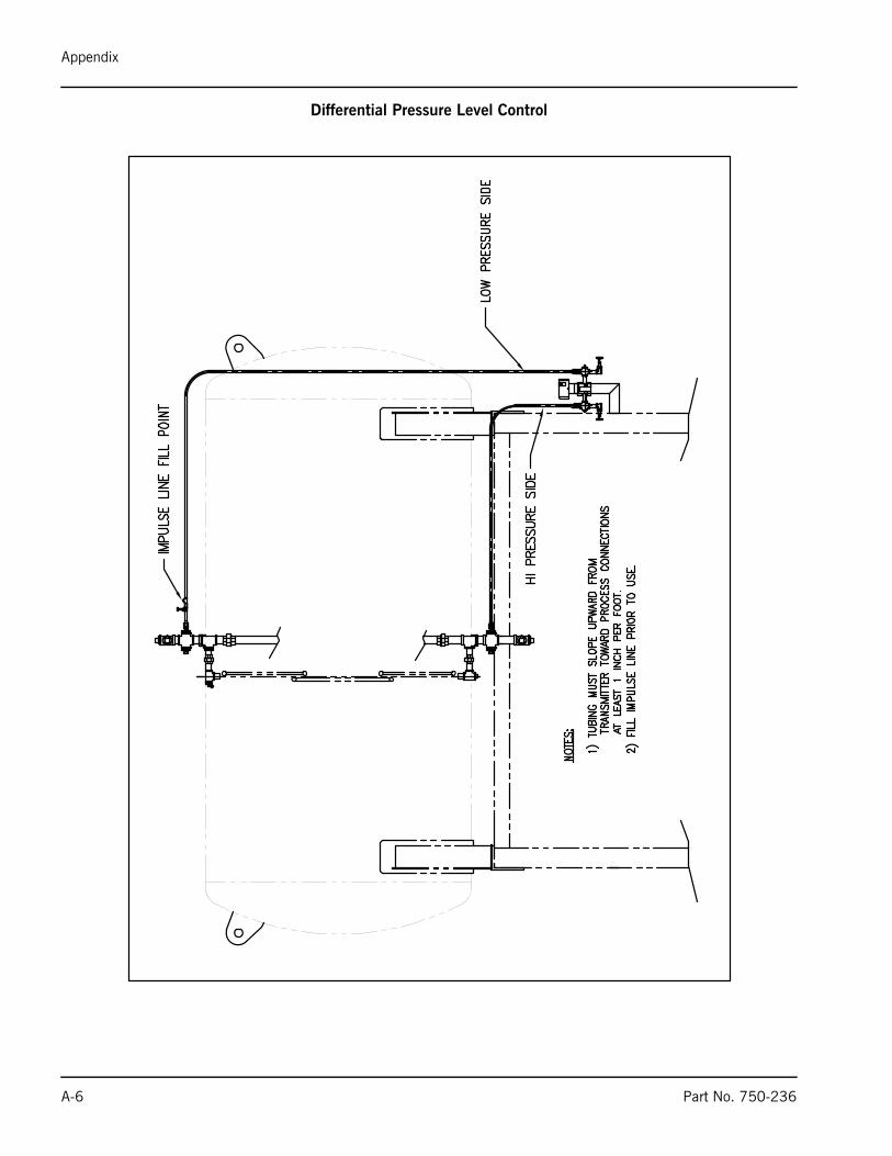
E. Differential Pressure Level Transmitter
Commissioning
This procedure applies only to differential pressure transmittersused for level measurement on pressurized closed pressure vessels(boiler drum or deaerator).
1. Make sure that power to the transmitter is “OFF”.2. With stop valves on the pressure vessel side closed, fill the
impulse line going to the low-pressure side of transmitter with distilled water.
3. Open low and high pressure valves on the vessel side to fill impulse lines with water.
4. Slowly open the high pressure valve on the transmitter side (part of 3-valve manifold) to fill the transmitter pressure-detector sec-tion with water.
5. Slowly open the low pressure valve on the transmitter side (part of 3-valve manifold) to fill the transmitter pressure-detector sec-tion with water.
6. Check that there are no leaks in the impulse piping, 3-valve manifold, transmitter or other components.
Figure 2-8 Recirculation Valve Figure 2-9 Level Transmitter and Float
Note: For magnetic sensor level charts and installation diagram, see Appendix pp. A-2—A-4.
Note: For differential pressure transmitter installation diagram see Appendix p. A-5.
2-6 Part No. 750-236

Chapter 2 — System Components
7. To vent air from the impulse lines and transmitter, slowly open vent plug on the transmitter (one side at the time) until only liq-uid is coming from the plug orifice. Tighten vent plugs.
8. Turn on power to the transmitter.9. Confirm transmitter operation.
To Re-span Rosemount 3051 Transmitter1. On the top of the transmitter head locate Zero (Z) and Span (S)
buttons.2. Fill reference leg (low pressure side) with water.3. On the three valve bypass manifold open high pressure side
valve, close low pressure side valve and open bypass valve.4. Loosen bleed nut on the high pressure side and wait until only
water is coming out (no air). Repeat for the low pressure side.5. Close bypass valve and open low pressure side valve. 6. Fill deaerator with water to the button of the gauge glass and
press Zero button. Hold Zero button for at least 2 seconds. 7. Fill deaerator with water to the top of the gauge glass and press
Span button. Hold Span button for at least 2 seconds. 8. Measure the length of the gauge glass. 9. On the PanelView screen for transmitter calibration. Zero = 0.
Span = Length of the gauge glass.
Part No. 750-236 2-7

Chapter 2 — System Components
2-8 Part No. 750-236

www.cleaverbrooks.com
Chapter 3
Commissioning
HMI Navigation . . . . . . . . . . . . . . . . . . . . . . . . . . . . . . . . . . . . . . . . 3-2Entering values on the HMI screens . . . . . . . . . . . . . . . . . . . . . . . . . . 3-3Main Menu . . . . . . . . . . . . . . . . . . . . . . . . . . . . . . . . . . . . . . . . . . . 3-3Configuring I/O Modules . . . . . . . . . . . . . . . . . . . . . . . . . . . . . . . . . . 3-4DA Tank Options . . . . . . . . . . . . . . . . . . . . . . . . . . . . . . . . . . . . . . . 3-5Surge Tank Options . . . . . . . . . . . . . . . . . . . . . . . . . . . . . . . . . . . . . 3-6Analog Input Configuration . . . . . . . . . . . . . . . . . . . . . . . . . . . . . . . . 3-7Feed Pump Configuration . . . . . . . . . . . . . . . . . . . . . . . . . . . . . . . . . 3-8Transfer Pump Configuration . . . . . . . . . . . . . . . . . . . . . . . . . . . . . . 3-10Boiler Feedwater Header Pressure Control . . . . . . . . . . . . . . . . . . . . 3-10Transfer Header Pressure Control . . . . . . . . . . . . . . . . . . . . . . . . . . . 3-11DA Primary Makeup Valve Control . . . . . . . . . . . . . . . . . . . . . . . . . . 3-12DA Secondary Makeup Valve Control . . . . . . . . . . . . . . . . . . . . . . . . 3-13Surge Primary Makeup Valve Control . . . . . . . . . . . . . . . . . . . . . . . . 3-13Surge Secondary Makeup Valve Control . . . . . . . . . . . . . . . . . . . . . . 3-13DA Tank PRV Steam Valve Control . . . . . . . . . . . . . . . . . . . . . . . . . . 3-13Chemical Feed Configuration . . . . . . . . . . . . . . . . . . . . . . . . . . . . . 3-14Ethernet Configuration . . . . . . . . . . . . . . . . . . . . . . . . . . . . . . . . . . 3-15Display Configuration . . . . . . . . . . . . . . . . . . . . . . . . . . . . . . . . . . . 3-16

Chapter 3 — Commissioning
3.1-HMI NavigationThe HMI push buttons are used to navigate to different screens andto enter operating parameters.
Some screens are password protected and should only be accessedby qualified personnel.
When a password-protected button is pressed, a password keypadwill be displayed. Enter the user name and password and press the<Enter> key to log in.
Note: When transitioning from one screen to another, the passworddoes not need to be re-entered. If a transition is made from a lowersecurity level screen to a higher security level screen, the passwordwill again be required before continuing.
Note that there are 3 levels of password protected screens, Operator,Service, and Factory. Passwords are available from your Cleaver-Brooks representative.
GREEN pushbuttons start/activate devices.
RED pushbuttons stop/deactivate devices.
3-2 Part No. 750-236

Chapter 3 — Commissioning
3.2-Entering values on the HMI screensScreens containing user-modifiable values will show a <Change>pushbutton. To change a value, press <Change>; the numerickeypad will appear. Enter the desired value and press <Enter>.
The keypad will close and the chosen value will be displayed on the<Change> button. Next, press the pushbutton for the value to bechanged (<Span>, for example). The new value will be displayedon the selected button.
If the entered value is not within the acceptable range for the chosenparameter, an “Out of Range’ message will appear next to the<Change> button. To continue, press <Change> again and repeatthe above steps.
If an out-of-range value is entered, the <Change> button will resetto zero if a new value is not entered within 60 seconds.
Note: Screen layouts may differ between single tank and two tanksystems. This manual will use the 2 tank system screens forexamples.
Note: It may be convenient toremove the alarm relay untilsys tem con f igu ra t i on i scomplete. The alarm circuit isdesigned to energize the relaywh i l e the sys tem i sfunctioning normally. In theevent of an alarm conditionthe relay will de-energize,causing the alarm to sound.
3.3-Main MenuOn system power-up, the Main Menu is displayed. This screenprovides pushbutton access to the various Operator, Configuration,and Alarm screens.
Figure 3-1 Main Menu
Note: Prior to commissioning the controls, ensure transmittershave been correctly installed. See previous chapter, SystemComponents. See also Appendix p. A-4 (magnetic transmitter) orA-5 (differential pressure transmitter).
Part No. 750-236 3-3
Chapter 3 — Commissioning
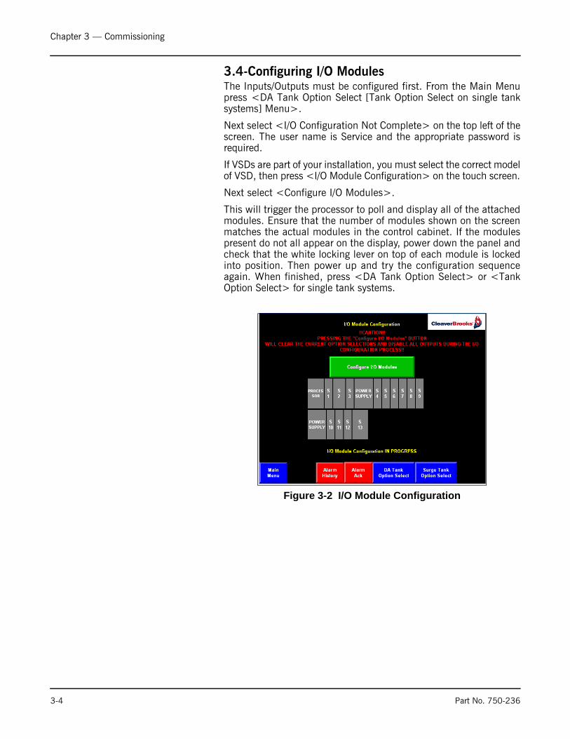
3.4-Configuring I/O ModulesThe Inputs/Outputs must be configured first. From the Main Menupress <DA Tank Option Select [Tank Option Select on single tanksystems] Menu>.
Next select <I/O Configuration Not Complete> on the top left of thescreen. The user name is Service and the appropriate password isrequired.
If VSDs are part of your installation, you must select the correct modelof VSD, then press <I/O Module Configuration> on the touch screen.
Next select <Configure I/O Modules>.
This will trigger the processor to poll and display all of the attachedmodules. Ensure that the number of modules shown on the screenmatches the actual modules in the control cabinet. If the modulespresent do not all appear on the display, power down the panel andcheck that the white locking lever on top of each module is lockedinto position. Then power up and try the configuration sequenceagain. When finished, press <DA Tank Option Select> or <TankOption Select> for single tank systems.
Figure 3-2 I/O Module Configuration
3-4 Part No. 750-236

Chapter 3 — Commissioning
3.5-DA Tank OptionsPress <Tank Type> to choose either Duo Tank or Two Tankinstallation.
Use the remaining buttons on this screen to turn on all optionspresent on the DA tank. Selections will turn green when enabled.
Note: All pumps must be off to change options.
Additional buttons on the Option Select screen perform thefollowing functions:
• Select between VSD or Contactor feed pump control.• Select the number of boiler feed pumps using the change button to enter.• Select between Common Header or 1 pump per boiler installation.Note: Common header installations require the header pressure sensor• Enable or disable the DA primary and secondary makeup valves as required by
your installation.• Toggle the analog output signal to the DA primary and secondary makeup valve:
Direct Acting: 4mA = valve closed; 20mA = valve fully openedReverse Acting: 4mA = valve fully opened; 20mA = valve closed
• Enable/disable the pump proving switch alarms (if applicable).• Enable/disable the steam PRV valve as required for your installation. Note: The Steam PRV Valve option requires a steam space pressure transmitter
and PRV with a 4-20 mA positioner.• Toggle the analog output signal to the PRV valve:
Direct Acting: 4mA = valve closed; 20mA = valve fully openedReverse Acting: 4mA = valve fully opened; 20mA = valve closed
• Enable/disable the DA recirculation valve as required for your installation. • Enable/disable DA chemical feed.• Enable/disable DA overflow modulation valve• Enable/disable primary MUV bias (see 3.12-DA Primary Makeup Valve Control).
Figure 3-3 DA Tank Option Selection
Part No. 750-236 3-5
Chapter 3 — Commissioning
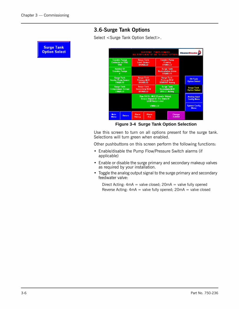
3.6-Surge Tank OptionsSelect <Surge Tank Option Select>.
Use this screen to turn on all options present for the surge tank.Selections will turn green when enabled.
Other pushbuttons on this screen perform the following functions:
• Enable/disable the Pump Flow/Pressure Switch alarms (if applicable)
• Enable or disable the surge primary and secondary makeup valves as required by your installation.
• Toggle the analog output signal to the surge primary and secondary feedwater valve:
Direct Acting: 4mA = valve closed; 20mA = valve fully openedReverse Acting: 4mA = valve fully opened; 20mA = valve closed
Figure 3-4 Surge Tank Option Selection
3-6 Part No. 750-236

Chapter 3 — Commissioning
3.7-Analog Input ConfigurationAfter configuring the I/O Modules, DA Tank options, and Surge Tankoptions, press <Analog Input Config Menu>. From this screen thespan, process set points, and alarm set points for all analog I/Odevices are set.
To configure Analog Input 1, press <DA Header Pressure>. Thefollowing screen will appear:
Use this screen to enter the desired values for Zero, Span, HighAlarm, Low Alarm, and Alarm Time.
To enter or change a value, press the <Change> button. When thenumeric keypad appears, enter desired value and press enter key.
Then press the button for the parameter that you wish tochange (Zero, Span, High Alarm, Low Alarm, or Alarm Time).
Figure 3-5 Analog Input Configuration
Figure 3-6 Analog Input Definition
Part No. 750-236 3-7

Chapter 3 — Commissioning
The Low Alarm value must be between the Zero value and the HighAlarm value. The High Alarm value must be between the Low Alarmvalue and the Span value.
To enable alarms, enter an Alarm Time value between 0.1 secondsand 32400.0 seconds (9 hours). To disable alarms, set the AlarmTime to 0 (zero) seconds.
After configuring Analog Input 1 (DA Header Pressure) press<Analog Input Config Menu> and repeat the above steps for theremaining inputs:
• Analog Input #2 DA Tank Temp• Analog Input #3 DA Tank Level• Analog Input #4 DA Tank Pressure• Analog Input #5 Surge Header Pressure• Analog Input #6 Surge Tank Temp• Analog Input #7 Surge Tank Level
3.8-Feed Pump ConfigurationAfter configuring the Analog Inputs, press <System Config Menu>.On the Configuration menu press <Feed Pump Config>. Thefollowing screen will appear:
Set the following values:
• If this system uses Variable Speed Drives for the feed pumps:
1. Enter the START LAG%. Allowable values are 0 (zero)% to STOP LAG%.
2. Enter the STOP LAG%. Allowable values are START LAG% to 100%.3. Enter the START Delay time. Allowable values are 0 to 300 seconds.4. Enter the STOP Delay time. Allowable values are 0 to 999 seconds.
System Configuration Menu
Figure 3-7 Feed Pump Configuration
3-8 Part No. 750-236

Chapter 3 — Commissioning
• If this system uses Motor Starters/Contactors (standard) for the feed pumps:
1. Enter the START LAG PSI. Allowable values are either:
Boiler Feedwater Header Pressure Zero to STOP LAG PSI if boiler feedwater header pressure alarms are disabled (AlarmTime = 0).
or
Boiler Feedwater Header Pressure Low Alarm value to STOP LAG PSI if boiler feedwater header pressure alarms are enabled (AlarmTime K0).
2. Enter the STOP LAG PSI. Allowable values are either:
START LAG PSI to Boiler Feedwater Header Pressure Span if boiler feedwater header pressure alarms are disabled (AlarmTime = 0).
or
START LAG PSI/Boiler Feedwater Header Pressure Low Alarm value to Boiler Feedwater Header Pressure High Alarm value if the boiler feedwater header pressure alarms are enabled (AlarmTime K0).
3. Enter the START LAG Delay time. Allowable values are 0 to 20 seconds.
4. Enter the STOP LAG Delay time. Allowable values are 0 to 999 seconds.
5. Enter the Alternate Feed Pump time increment. Allowable values are 0 hours (alternate disabled) to 9999 hours.
The Lead/Lag function can be started or stopped using the <START(STOP) LEAD-LAG> pushbutton.
The Alternate function can be started or stopped using the <START(STOP) ALTERNATE> pushbutton.
• Pump Auto-Restart
If enabled, will automatically restart the feed pump when the DAtank water level exceeds the value entered in “Pump Auto-RestartLevel”.
Part No. 750-236 3-9

Chapter 3 — Commissioning
3.9-Transfer Pump ConfigurationNext, from the System Configuration screen, press <Transfer PumpConfig>.
Remaining entries are similar to Feed Pump Configuration.
3.10-Boiler Feedwater Header Pressure ControlPID tuning and Manual/Auto control for the feed pump VSDs areaccessed through these screens. Press <Feed Pump VSD Control>from the Main Menu.
First set the DA header pressure set point. Allowable values areeither:
Boiler Feedwater Header Pressure Zero to Boiler Feedwater Header Pressure Span if Boiler Feedwater Header Pressure Alarms are disabled (Alarm Time = 0).
or
Figure 3-8 Transfer Pump Configuration
3-10 Part No. 750-236

Chapter 3 — Commissioning
Boiler Feedwater Header Pressure Low Alarm value to Boiler Feedwater Header Pressure High Alarm value if Boiler Feedwater Header Pressure Alarms are enabled (Alarm Time K0).
Next enter the PID gain values. These values will vary based on theapplication. Allowable values are 0.0 to 999.0 (D gain is typicallyset to 0).
The <Man> and <Auto> pushbuttons are used to toggle VSDcontrol between Manual and Automatic mode. In Manual mode the<Increase (Decrease) VSD%> buttons are used to manually controlVSD output. In Automatic mode, the PLC controls VSD outputbased on the set point and PID settings.
NOTE: In order to manually start/stop individual pumps, pump leadlag must be disabled.
3.11-Transfer Header Pressure ControlPID tuning and Manual/Auto control for the transfer pump VSDs areaccessed through these screens. Press <Transfer Pump VSDControl> from the Main Menu.
First set the Surge header pressure set point. Allowable values areeither:
Transfer Header Pressure Zero to Transfer Header Pressure Span if Transfer Header Pressure Alarms are disabled (Alarm Time = 0).
or
Transfer Header Pressure Low Alarm value to Transfer Header Pressure High Alarm value if Boiler Feedwater Header Pressure Alarms are enabled (Alarm Time K0).
Next enter the PID gain values. These values will vary based on theapplication. Allowable values are 0.0 to 999.0 (D gain is typicallyset to 0).
Part No. 750-236 3-11

Chapter 3 — Commissioning
The <Manual> and <Auto> pushbuttons are used to toggle VSDcontrol between Manual and Automatic mode. In Manual mode the<Increase (Decrease) VSD%> buttons are used to manually controlVSD output. In Automatic mode, the PLC controls VSD outputbased on the set point and PID settings.
NOTE: In order to manually start/stop individual pumps, pump leadlag must be disabled.
3.12-DA Primary Makeup Valve ControlReturn to the Main Menu and press <DA Primary Makeup ValveControl>.
PID tuning and Manual/Auto control for the DA feedwater valve areaccessed through these screens.
First set the DA tank water level set point (inches). Allowable valuesare:
DA Tank Level Zero to DA Tank Level Span if DA Tank Level Alarms are disabled (Alarm Time = 0).
or
DA Tank Level Low Alarm value to DA Tank Level High Alarm value if DA Tank Level Alarms are enabled (Alarm Time K0).
Next enter the PID gain values. These values will vary based on theapplication. Allowable values are 0.0 to 999.0 (D gain is typicallyset to 0).
The <Manual> and <Auto> pushbuttons are used to toggle feedwater valve control between Manual and Automatic mode. InManual mode the <Open (Close)> buttons are used to manuallyopen and close the feedwater valve. In Automatic mode, the PLCcontrols the valve based on the set point and PID settings.
Figure 3-9 DA Feedwater Valve Tuning
3-12 Part No. 750-236

Chapter 3 — Commissioning
If “Bias DA Primary MUV on LOW Surge Level” is enabled (see DATank Options), the Setpoints 1 and 2 and bias amount can beadjusted from this screen. At Setpoint 1 the MUV bias is at 0%. AtSetpoint 2 the bias is at 100% and the MUV will be fully closed.
3.13-DA Secondary Makeup Valve ControlSettings are similar to DA Primary MUV Control (setpoint is typicallyset higher than Primary setpoint).
3.14-Surge Primary Makeup Valve ControlIf the system is equipped with a surge tank, a <Surge PrimaryMakeup Valve> button will appear on the Main screen. Use thisbutton to access the Surge Primary Makeup Valve control screen.
Surge Primary Makeup Valve tuning parameters are configured in asimilar manner as those for the DA Primary Makeup Valve.
3.15-Surge Secondary Makeup Valve ControlSettings are similar to Surge Primary MUV Control (setpoint istypically set higher than Primary setpoint).
3.16-DA Tank PRV Steam Valve ControlIf the system is equipped with a DA tank PRV Steam Valve, a<Steam PRV Valve Control> pushbutton will appear on the MainMenu.
First set the DA Tank Pressure set point. Allowable values are either:
DA Tank Pressure Zero to DA Tank Pressure Span if the DA Tank Pressure alarms are disabled (Alarm Time = 0).
or
Part No. 750-236 3-13

Chapter 3 — Commissioning
DA Tank Pressure Low Alarm value to DA Tank Pressure High Alarm value if DA Tank Pressure alarms are enabled (Alarm Time K0).
Next enter the PID Gain values. These values will vary based on theapplication. Allowable values are 0.0 to 999.0 (D gain is typicallyset to 0).
The <Manual> and <Auto> pushbuttons are used to toggle PRVSteam Valve control between Manual and Automatic mode. InManual mode the <Open (Close) Valve> buttons are used tomanually open and close the PRV valve. In Automatic mode, thePLC controls the valve based on the set point and PID settings.
3.17-Chemical Feed ConfigurationIf the system is equipped with a DA and/or Surge chemical feedsystem, when selected the appropriate pushbutton will appear onthe System Configuration Menu.
To configure the chemical feed system, enter values for STARTChemical Feed Time Delay and STOP Chemical Feed Time Delay.Allowable range is 0 to 32400 seconds (9 hours).
The start and stop delays function as follows:
When any DA feed pump is ON and in AUTO mode (PLC control)and the START Chemical Feed Time Delay has elapsed, thechemical feed contact will CLOSE.
When all of the DA feed pumps are OFF (or if no pumps are inAUTO) and the STOP Chemical Feed Time Delay has elapsed, thechemical feed contact will OPEN.
Manual DA chemical feed does not utilize the START/STOP delays.While the <Manual DA Chemical Feed> button is held, thechemical feed contact will be CLOSED.
Figure 3-10 DA Chemical Feed Configuration
3-14 Part No. 750-236

Chapter 3 — Commissioning
When the <Manual DA Chemical Feed> button is released, thechemical feed contact will OPEN unless there is a DA feed pumpON and in AUTO. In this case, the chemical feed contact will notOPEN until all of the DA feed pumps are OFF and the STOPChemical Feed Time Delay has elapsed.
After configuring DA Chemical Feed, repeat steps for SurgeChemical Feed (if applicable). Surge chemical feed is based uponthe transfer pumps running.
3.18-Ethernet ConfigurationTo establish Ethernet communications, certain information needs tobe entered on the Ethernet Configuration screen, accessible bypressing <Ethernet Config> on the System Configuration menu.
The following items can be configured from this screen:
• ADAC IP Address - This address and the Subnet Mask are required to allow access to a local area network. These addresses need to be obtained from your local information management department. Use the <Change> button to modify the values.
• ADAC Subnet Mask - See ADAC IP Address.
• Gateway - Used to communicate with other networks. This address needs to be obtained from your local information management department. Use the <Change> button to modify the values.
This default Ethernet addressing is as follows:
Figure 3-11 Ethernet Configuration
Part No. 750-236 3-15

Chapter 3 — Commissioning
When changing these settings, press the <Configure Ethernet> button after making changes. This will automatically update the PLC Ethernet settings, provided the PLC and HMI are currently communicating.
3.19-Display ConfigurationMost of the PanelView parameters are preset and should not be changed. PV configuration does, however, allow setting of the date and time. Press <PanelView Config> from the Main Menu to access. You will be prompted for a password.
To change the date, select Terminal Settings>Time/Date/Regional Settings>Date.
To change the time, select Terminal Settings>Time/Date/Regional Settings>Time.
Table 3-1 Cleaver-Brooks Default Ethernet Addresses
ADAC IP Address ADAC Subnet Mask GatewayADAC DA Single Tank PLC 192.168.1.150 255.255.255.0 192.168.1.1ADAC Surge Single Tank 192.168.1.150 255.255.255.0 192.168.1.1ADAC Dual Tank PLC 192.168.1.150 255.255.255.0 192.168.1.1
Note: For additional PanelView Plus setup information see“Procedure to Load and Set Up a PV+ Rev3.doc”,available on the CB web site.
Figure 3-12. PanelView Plus Configuration Screen
3-16 Part No. 750-236

Chapter 3 — Commissioning
Select the value to change. Enter the desired value in the numeric keypad and press return. When finished press the <EXIT> button.
The display has a screen saver feature. To enable and to adjust settings, go to Terminal Settings>Display>Screen Saver.
The Panel View software can be loaded or saved using a PCMCIA or SD memory card, depending on PV+ model. The card inserts into the side of the display. Go to Terminal Settings>File Management to access PV file management functions. “External Storage 1” refers to the memory card slot.
Figure 3-13. Date / Time Screens
Figure 3-14. Screen Setup
Part No. 750-236 3-17
Chapter 3 — Commissioning
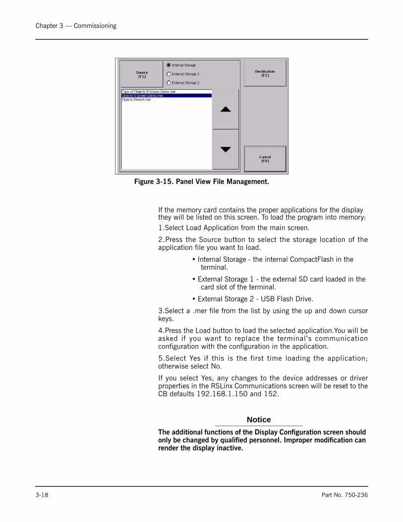
If the memory card contains the proper applications for the display they will be listed on this screen. To load the program into memory:1.Select Load Application from the main screen.
2.Press the Source button to select the storage location of theapplication file you want to load.
• Internal Storage - the internal CompactFlash in the terminal.
• External Storage 1 - the external SD card loaded in the card slot of the terminal.
• External Storage 2 - USB Flash Drive.
3.Select a .mer file from the list by using the up and down cursorkeys.
4.Press the Load button to load the selected application.You will beasked if you want to replace the terminal’s communicationconfiguration with the configuration in the application.
5.Select Yes if this is the first time loading the application;otherwise select No.
If you select Yes, any changes to the device addresses or driverproperties in the RSLinx Communications screen will be reset to theCB defaults 192.168.1.150 and 152.
Notice
The additional functions of the Display Configuration screen should only be changed by qualified personnel. Improper modification can render the display inactive.
Figure 3-15. Panel View File Management.
3-18 Part No. 750-236
www.cleaverbrooks.com
Chapter 4
Operation
System Control/Operation . . . . . . . . . . . . . . . . . . . . . . . . . . . . . . . . . 4-2Screen Select . . . . . . . . . . . . . . . . . . . . . . . . . . . . . . . . . . . . . 4-2DA Tank Overview . . . . . . . . . . . . . . . . . . . . . . . . . . . . . . . . . 4-2Surge Tank Overview . . . . . . . . . . . . . . . . . . . . . . . . . . . . . . . 4-3Duo Tank Overview . . . . . . . . . . . . . . . . . . . . . . . . . . . . . . . . . 4-4Feed Pump Control . . . . . . . . . . . . . . . . . . . . . . . . . . . . . . . . . 4-4Transfer Pump Control . . . . . . . . . . . . . . . . . . . . . . . . . . . . . . 4-6
Alarms . . . . . . . . . . . . . . . . . . . . . . . . . . . . . . . . . . . . . . . . . . . . . . 4-6Alarm Banner . . . . . . . . . . . . . . . . . . . . . . . . . . . . . . . . . . . . 4-6Alarm History . . . . . . . . . . . . . . . . . . . . . . . . . . . . . . . . . . . . . 4-7
Chapter 4 — Operation
4.1-System Control/Operation
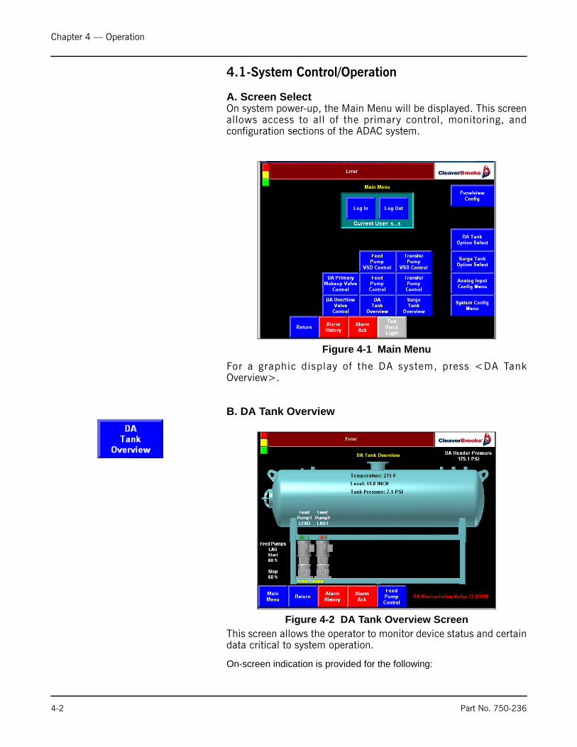
A. Screen SelectOn system power-up, the Main Menu will be displayed. This screenallows access to all of the primary control, monitoring, andconfiguration sections of the ADAC system.
For a graphic display of the DA system, press <DA TankOverview>.
B. DA Tank Overview
This screen allows the operator to monitor device status and certaindata critical to system operation.
On-screen indication is provided for the following:
Figure 4-1 Main Menu
Figure 4-2 DA Tank Overview Screen
4-2 Part No. 750-236
Chapter 4 — Operation
• DA Recirc Valve status – OPEN/CLOSED • DA Header Pressure• DA Tank Temperature • DA Tank Level • DA Tank Pressure • Lead-Lag status (Lead, Lag1, Lag2, etc.) for each of the Feed
Pumps• OFF/ON/FAULT status for each of the Feed Pumps• Start LAG and Stop LAG data
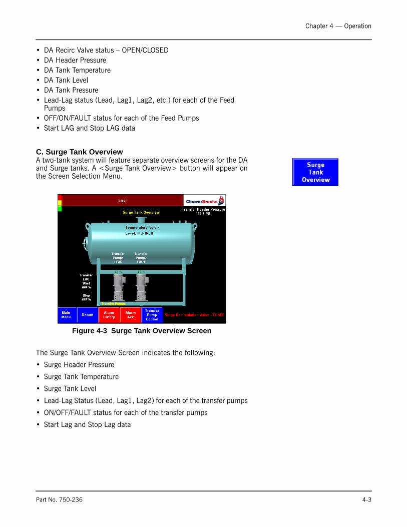
C. Surge Tank OverviewA two-tank system will feature separate overview screens for the DAand Surge tanks. A <Surge Tank Overview> button will appear onthe Screen Selection Menu.
The Surge Tank Overview Screen indicates the following:
• Surge Header Pressure
• Surge Tank Temperature
• Surge Tank Level
• Lead-Lag Status (Lead, Lag1, Lag2) for each of the transfer pumps
• ON/OFF/FAULT status for each of the transfer pumps
• Start Lag and Stop Lag data
Figure 4-3 Surge Tank Overview Screen
Part No. 750-236 4-3

Chapter 4 — Operation
D. Duo Tank Overview
If a DUO TANK system has been selected in the Option Selectscreen, a <Tank Overview> button will be available on the MainMenu for access to the Duo Tank Overview screen. Features aresimilar to the DA/Surge Overview screens.
E. Feed Pump Control
The Feed Pump Control Screen provides an indication of the following items:
Figure 4-4 Duo Tank Overview Screen
Figure 4-5 Feed Pump Control Screen
4-4 Part No. 750-236
Chapter 4 — Operation
• DA Header Pressure• Status of the optional Flow Switches – OPEN/CLOSED• Selector Switch Position HAND/OFF/AUTO• OFF/ON/FAULT status for each of the Feed Pumps• Lead-Lag status (Lead, Lag1, Lag2, etc.) for each of the Feed
Pumps• Elapsed Run Time for each Feed Pump• Feed Pump Alternate Time increment• Lead Pump Elapsed Time (when the Alternate function is active)
The Feed Pump Control Screen provides the following Control Functions:
• Individual Feed Pump START/STOP Push Buttons
When the Selector Switch is in AUTO(PLC) and the LEAD/LAG is OFF, the START/STOP Push Button can be used to START/STOP the corresponding Feed Pump.
If the LEAD/LAG is ON, the START/STOP Push Buttons are not active.
• Individual Feed Pump LEAD/LAG assignment Push Buttons
These Push Buttons are used to assign the LEAD Pump and the LAG Pump Sequence. Each Feed Pump must have its own unique value or an “INVALID LEAD/LAG CFG” indicator will appear on the screen. Once a valid Lead-Lag Configuration has been selected, after a short time delay, a “SAVING LEAD/LAG CFG” indicator will appear on the screen.
• START LEAD/LAG Push Button. This button will START and STOP the Lead-Lag sequencing.
To START the LEAD/LAG function: At least two Feed Pumps need to be Configured (present in the system) and have the Selector Switch in the AUTO position.
When the Lead-Lag sequence is started, if a pump(s) has been started with the Individual Feed Pump START/STOP Push Button, if that pump is not the LEAD Pump, it will be shut off. The LEAD Pump will be Started.
If one or more of the LAG Pumps is required, they will be Started.
When the LEAD/LAG function is turned off (LEAD/LAG STOP Push Button), the Feed Pumps will be OFF.
• The <START ALTERNATE> Push Button. If an Alternate Feed Pump Time value has been entered (on the Feed Pump Config screen), The Feed Pump Alternate sequence can be Started and Stopped using the <START ALTERNATE> Push Button.
• The <RESET Hours> and the <RESET Elapsed Time> push buttons can be used to reset the corresponding elapsed time values to 0 (zero).
Part No. 750-236 4-5

Chapter 4 — Operation
F. Transfer Pump Control
Information and controls on this screen are similar to Feed PumpControl above.
4.2-Alarms
A. Alarm Banner
Any active alarms will appear on the Alarm Banner screen. Activealarms must be acknowledged using the <Ack> button on thisscreen, or by using the <Alarm Ack> button which appears in thelower right corner of most other HMI screens.
Following are examples of some ADAC system alarms:
Figure 4-6 Transfer Pump Control Screen
Figure 4-7 Alarm Banner Screen
4-6 Part No. 750-236
Chapter 4 — Operation
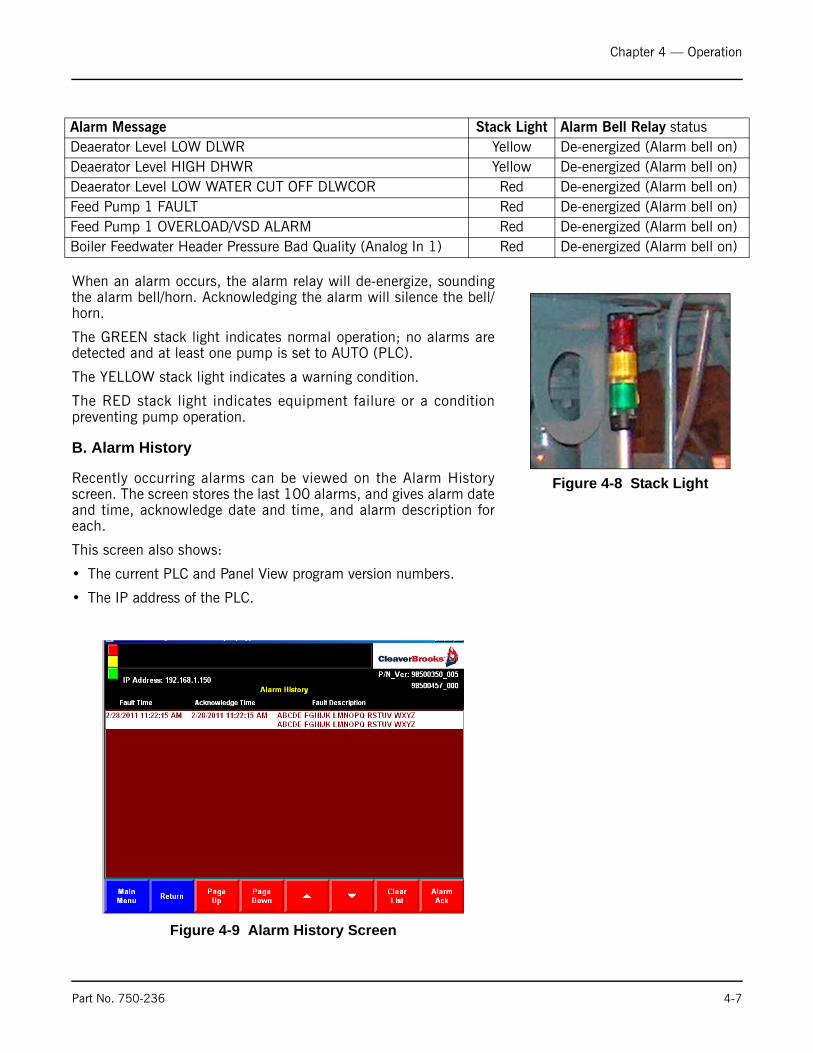
When an alarm occurs, the alarm relay will de-energize, soundingthe alarm bell/horn. Acknowledging the alarm will silence the bell/horn.
The GREEN stack light indicates normal operation; no alarms aredetected and at least one pump is set to AUTO (PLC).
The YELLOW stack light indicates a warning condition.
The RED stack light indicates equipment failure or a conditionpreventing pump operation.
B. Alarm History
Recently occurring alarms can be viewed on the Alarm Historyscreen. The screen stores the last 100 alarms, and gives alarm dateand time, acknowledge date and time, and alarm description foreach.
This screen also shows:
• The current PLC and Panel View program version numbers.
• The IP address of the PLC.
Alarm Message Stack Light Alarm Bell Relay statusDeaerator Level LOW DLWR Yellow De-energized (Alarm bell on)Deaerator Level HIGH DHWR Yellow De-energized (Alarm bell on)Deaerator Level LOW WATER CUT OFF DLWCOR Red De-energized (Alarm bell on)Feed Pump 1 FAULT Red De-energized (Alarm bell on)Feed Pump 1 OVERLOAD/VSD ALARM Red De-energized (Alarm bell on)Boiler Feedwater Header Pressure Bad Quality (Analog In 1) Red De-energized (Alarm bell on)
Figure 4-8 Stack Light
Figure 4-9 Alarm History Screen
Part No. 750-236 4-7

Chapter 4 — Operation
4-8 Part No. 750-236

Milwaukee, Wisconsin
www.cleaver-brooks.com
Chapter 5
Input/Output ListsSingle Tank PLC I/O Layout ..................................................... 5-2Two Tank PLC I/O Layout ........................................................ 5-5

Chapter 5 — Input/Output Lists
5.1-SINGLE TANK PLC I/O LAYOUT
BANK 1 = Slots 0-9BANK 2 = Slots 10-12
SLOT 1 - DISCRETE INPUTS SLOT 2 - DISCRETE OUTPUTS
IN 0 PUMP 1 ON / VSD RUN CONTACT OUT 0 PUMP 1 START (PR1) / VSD RUN
IN 1 PUMP 1 O/L / VSD ALARM OUT 1 PUMP 2 START (PR2) / VSD RUNIN 2 PUMP 1 IN AUTO OUT 2 PUMP 3 START (PR3) / VSD RUNIN 3 PUMP 2 ON / VSD RUN CONTACT OUT 3 PUMP 4 START (PR4) / VSD RUNIN 4 PUMP 2 O/L / VSD ALARM OUT 4 PUMP 5 START (PR5) / VSD RUNIN 5 PUMP 2 IN AUTO OUT 5 PUMP 6 START (PR6) / VSD RUNIN 6 PUMP 3 ON / VSD RUN CONTACT OUT 6IN 7 PUMP 3 O/L / VSD ALARM OUT 7IN 8 PUMP 3 IN AUTO OUT 8IN 9 PUMP 4 ON / VSD RUN CONTACT OUT 9 NO ALARMS (AR)IN 10 PUMP 4 O/L / VSD ALARM OUT 10 RED STACK LIGHT (RSL)IN 11 PUMP 4 IN AUTO OUT 11 YELLOW STACK LIGHT (YSL)IN 12 PUMP 5 ON / VSD RUN CONTACT OUT 12 GREEN STACK LIGHT (GSL)IN 13 PUMP 5 O/L / VSD ALARM OUT 13 CHEMICAL FEED RELAY (CRF)IN 14 PUMP 5 IN AUTO OUT 14IN 15 LOW-LOW WATER LEVEL (LWCO) SW OUT 15 RECIRC VALVE
5-2 Part No. 750-236
Chapter 5 — Input/Output Lists
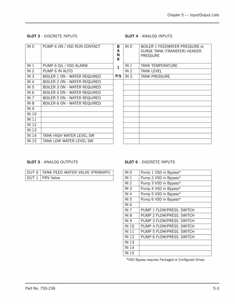
SLOT 3 - DISCRETE INPUTS SLOT 4 - ANALOG INPUTS
IN 0 PUMP 6 ON / VSD RUN CONTACT BANK
1
P/S
IN 0 BOILER 1 FEEDWATER PRESSURE or SURGE TANK (TRANSFER) HEADER PRESSURE
IN 1 PUMP 6 O/L / VSD ALARM IN 1 TANK TEMPERATUREIN 2 PUMP 6 IN AUTO IN 2 TANK LEVELIN 3 BOILER 1 ON - WATER REQUIRED IN 3 TANK PRESSUREIN 4 BOILER 2 ON - WATER REQUIREDIN 5 BOILER 3 ON - WATER REQUIREDIN 6 BOILER 4 ON - WATER REQUIREDIN 7 BOILER 5 ON - WATER REQUIREDIN 8 BOILER 6 ON - WATER REQUIREDIN 9IN 10IN 11IN 12IN 13IN 14 TANK HIGH WATER LEVEL SWIN 15 TANK LOW WATER LEVEL SW
SLOT 5 - ANALOG OUTPUTS SLOT 6 - DISCRETE INPUTS
OUT 0 TANK FEED WATER VALVE (PRIMARY) IN 0 Pump 1 VSD in Bypass*OUT 1 PRV Valve IN 1 Pump 2 VSD in Bypass*
IN 2 Pump 3 VSD in Bypass*IN 3 Pump 4 VSD in Bypass*IN 4 Pump 5 VSD in Bypass*IN 5 Pump 6 VSD in Bypass*IN 6IN 7 PUMP 1 FLOW/PRESS. SWITCHIN 8 PUMP 2 FLOW/PRESS. SWITCHIN 9 PUMP 3 FLOW/PRESS. SWITCHIN 10 PUMP 4 FLOW/PRESS. SWITCHIN 11 PUMP 5 FLOW/PRESS. SWITCHIN 12 PUMP 6 FLOW/PRESS. SWITCHIN 13IN 14IN 15
*VSD Bypass requires Packaged or Configured Drives
Part No. 750-236 5-3
Chapter 5 — Input/Output Lists
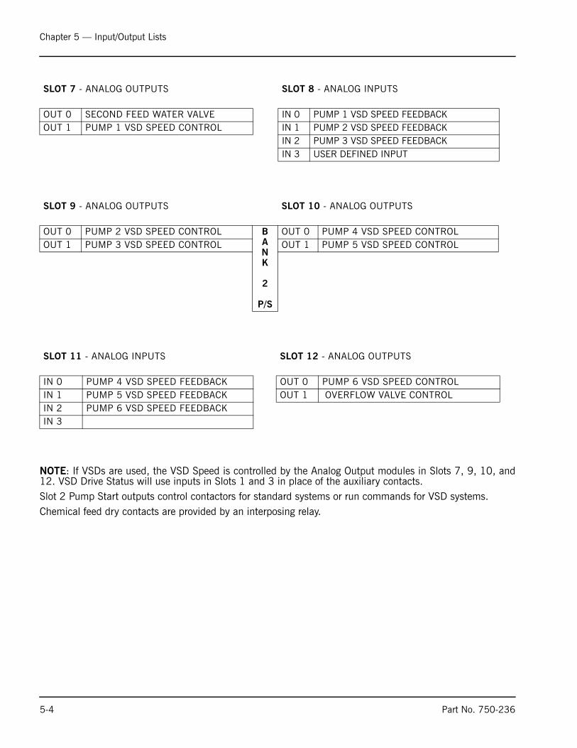
NOTE: If VSDs are used, the VSD Speed is controlled by the Analog Output modules in Slots 7, 9, 10, and12. VSD Drive Status will use inputs in Slots 1 and 3 in place of the auxiliary contacts.Slot 2 Pump Start outputs control contactors for standard systems or run commands for VSD systems.Chemical feed dry contacts are provided by an interposing relay.
SLOT 7 - ANALOG OUTPUTS SLOT 8 - ANALOG INPUTS
OUT 0 SECOND FEED WATER VALVE IN 0 PUMP 1 VSD SPEED FEEDBACKOUT 1 PUMP 1 VSD SPEED CONTROL IN 1 PUMP 2 VSD SPEED FEEDBACK IN 2 PUMP 3 VSD SPEED FEEDBACK
IN 3 USER DEFINED INPUT
SLOT 9 - ANALOG OUTPUTS SLOT 10 - ANALOG OUTPUTS
OUT 0 PUMP 2 VSD SPEED CONTROL BANK
2
P/S
OUT 0 PUMP 4 VSD SPEED CONTROLOUT 1 PUMP 3 VSD SPEED CONTROL OUT 1 PUMP 5 VSD SPEED CONTROL
SLOT 11 - ANALOG INPUTS SLOT 12 - ANALOG OUTPUTS
IN 0 PUMP 4 VSD SPEED FEEDBACK OUT 0 PUMP 6 VSD SPEED CONTROLIN 1 PUMP 5 VSD SPEED FEEDBACK OUT 1 OVERFLOW VALVE CONTROLIN 2 PUMP 6 VSD SPEED FEEDBACK IN 3
5-4 Part No. 750-236

Chapter 5 — Input/Output Lists
5.2-TWO TANK PLC I/O LAYOUT
BANK 1 = Slots 0-9BANK 2 = Slots 10-13
SLOT 1 - DISCRETE INPUTS SLOT 2 - DISCRETE OUTPUTS
IN 0 BOILER FEED PUMP 1 ON / VSD RUN CONTACT OUT 0 BOILER FEED PUMP 1 START (PR1) / VSD RUN
IN 1 BOILER FEED PUMP 1 O/L / VSD ALARM OUT 1 BOILER FEED PUMP 2 START (PR2) / VSD RUN
IN 2 BOILER FEED PUMP 1 IN AUTO OUT 2 BOILER FEED PUMP 3 START (PR3) / VSD RUN
IN 3 BOILER FEED PUMP 2 ON / VSD RUN CONTACT OUT 3 BOILER FEED PUMP 4 START (PR4) / VSD RUN
IN 4 BOILER FEED PUMP 2 O/L / VSD ALARM OUT 4 BOILER FEED PUMP 5 START (PR5) / VSD RUN
IN 5 BOILER FEED PUMP 2 IN AUTO OUT 5 BOILER FEED PUMP 6 START (PR6) / VSD RUN
IN 6 BOILER FEED PUMP 3 ON / VSD RUN CONTACT OUT 6 TRANSFER PUMP 1 START (TPR1) / VSD RUN
IN 7 BOILER FEED PUMP 3 O/L / VSD ALARM OUT 7 TRANSFER PUMP 2 START (TPR2) / VSD RUN
IN 8 BOILER FEED PUMP 3 IN AUTO OUT 8 TRANSFER PUMP 3 START (TPR3) / VSD RUN
IN 9 BOILER FEED PUMP 4 ON / VSD RUN CONTACT OUT 9 NO ALARMS (AR)
IN 10 BOILER FEED PUMP 4 O/L / VSD ALARM OUT 10 RED STACK LIGHT (RSL)
IN 11 BOILER FEED PUMP 4 IN AUTO OUT 11 YELLOW STACK LIGHT (YSL)
IN 12 BOILER FEED PUMP 5 ON / VSD RUN CONTACT OUT 12 GREEN STACK LIGHT (GSL)
IN 13 BOILER FEED PUMP 5 O/L / VSD ALARM OUT 13 DA CHEMICAL FEED RELAY (CRF)
IN 14 BOILER FEED PUMP 5 IN AUTO OUT 14 FUTURE SURGE CHEMICAL FEED RELAY
IN 15 DA TANK LOW-LOW WATER LEVEL (LWCO) SW OUT 15 DA RECIRC VALVE
SLOT 3 - DISCRETE INPUTS SLOT 4 - DISCRETE INPUTS
IN 0 BOILER FEED PUMP 6 ON / VSD RUN CONTACT IN 0 DA TANK HIGH WATER LEVEL SW
IN 1 BOILER FEED PUMP 6 O/L / VSD ALARM IN 1 TRANSFER PUMP 3ON / VSD RUN CONTACT
IN 2 BOILER FEED PUMP 6 IN AUTO IN 2 TRANSFER PUMP 3 O/L / VSD ALARM
IN 3 BOILER 1 ON - WATER REQUIRED IN 3 TRANSFER PUMP 3 IN AUTO
IN 4 BOILER 2 ON - WATER REQUIRED IN 4 SURGE TANK LO-LOW WATER LEVEL (LWCO) SW
IN 5 BOILER 3 ON - WATER REQUIRED IN 5 SURGE TANK LOW WATER LEVEL SW
IN 6 BOILER 4 ON - WATER REQUIRED IN 6 SURGE TANK HIGH WATER LEVEL SW
IN 7 BOILER 5 ON - WATER REQUIRED IN 7 BF PUMP 1 FLOW/PRESSURE SWITCH
IN 8 BOILER 6 ON - WATER REQUIRED IN 8 BF PUMP 2 FLOW/PRESSURE SWITCH
IN 9 TRANSFER PUMP 1 ON / VSD RUN CONTACT IN 9 BF PUMP 3 FLOW/PRESSURE SWITCH
IN 10 TRANSFER PUMP 1 O/L / VSD ALARM IN 10 BF PUMP 4 FLOW/PRESSURE SWITCH
IN 11 TRANSFER PUMP 1 IN AUTO IN 11 BF PUMP 5 FLOW/PRESSURE SWITCH
IN 12 TRANSFER PUMP 2 ON / VSD RUN CONTACT IN 12 BF PUMP 6 FLOW/PRESSURE SWITCH
IN 13 TRANSFER PUMP 2 O/L / VSD ALARM IN 13 TR PUMP 1 FLOW/PRESSURE SWITCH
IN 14 TRANSFER PUMP 2 IN AUTO IN 14 TR PUMP 2 FLOW/PRESSURE SWITCH
IN 15 DA TANK LOW WATER LEVEL SW IN 15 TR PUMP 3 FLOW/PRESSURE SWITCH
Part No. 750-236 5-5

Chapter 5 — Input/Output Lists
SLOT 5 - ANALOG INPUTS SLOT 6 - ANALOG INPUTS
IN 0 BOILER 1 FEEDWATER PRESSURE or BOILER FEEDWATER HEADER PRESSURE
IN 0 SURGE TANK DISCHARGE (TRANSFER) HEADER PRESSURE
IN 1 DA TANK TEMPERATURE IN 1 SURGE TANK TEMPERATURE
IN 2 DA TANK LEVEL IN 2 SURGE TANK LEVEL
IN 3 DA TANK PRESSURE IN 3 USER DEFINED INPUT
SLOT 7 - ANALOG OUTPUTS SLOT 8 - ANALOG OUTPUTS
OUT 0 DA TANK FEED WATER VALVE (PRIMARY) OUT 0 PRV ValveOUT 1 SURGE TANK FEED WATER VALVE (PRIMARY) OUT 1 SECONDARY DA FEED WATER VALVE
SLOT 9 - ANALOG OUTPUTS SLOT 10 - ANALOG INPUTS
OUT 0 SECONDARY SURGE TANK FEED WATER VALVE BANK
2
P/S
IN 0 BOILER FEED PUMP 1 VSD SPEED FEEDBACKOUT 1 BOILER FEED PUMP 1 VSD SPEED CONTROL IN 1 BOILER FEED PUMP 2 VSD SPEED FEEDBACK IN 2 BOILER FEED PUMP 3 VSD SPEED FEEDBACK
IN 3 TRANSFER PUMP 1 VSD SPEED FEEDBACK
5-6 Part No. 750-236

Chapter 5 — Input/Output Lists
NOTE: If VSDs are used, VSD speed is controlled by the Analog Output modules in Slots 9 and 11. VSD DriveStatus will use inputs in Slots 1, 3, and 4 in place of the auxiliary contacts.Slot 2 Pump Start outputs control contactors for standard systems or run commands for VSD systems.Chemical feed dry contacts are provided by an interposing relay.
SLOT 11 - ANALOG OUTPUTS SLOT 12 - ANALOG INPUTS
OUT 0 BOILER FEED PUMP 2 VSD SPEED CONTROL IN 0 BOILER FEED PUMP 4 VSD SPEED FEEDBACK
OUT 1 BOILER FEED PUMP 3 VSD SPEED CONTROL IN 1 BOILER FEED PUMP 5 VSD SPEED FEEDBACK
OUT 2 BOILER FEED PUMP 4 VSD SPEED CONTROL IN 2 BOILER FEED PUMP 6 VSD SPEED FEEDBACK
OUT 3 BOILER FEED PUMP 5 VSD SPEED CONTROL IN 3 TRANSFER PUMP 2 VSD SPEED FEEDBACK
OUT 4 BOILER FEED PUMP 6 VSD SPEED CONTROL OUT 5 TRANSFER PUMP 1 VSD SPEED CONTROL
OUT 6 TRANSFER PUMP 2 VSD SPEED CONTROL
OUT 7 TRANSFER PUMP 3 VSD SPEED CONTROL
SLOT 13 - ANALOG INPUTS
IN 0 TRANSFER PUMP 3 VSD SPEED FEEDBACK
Part No. 750-236 5-7

Chapter 5 — Input/Output Lists
5-8 Part No. 750-236

www.cleaverbrooks.com
Chapter 6
PartsParts List .............................................................................. 6-2
Chapter 6 — Parts
6-2 Part No. 750-236
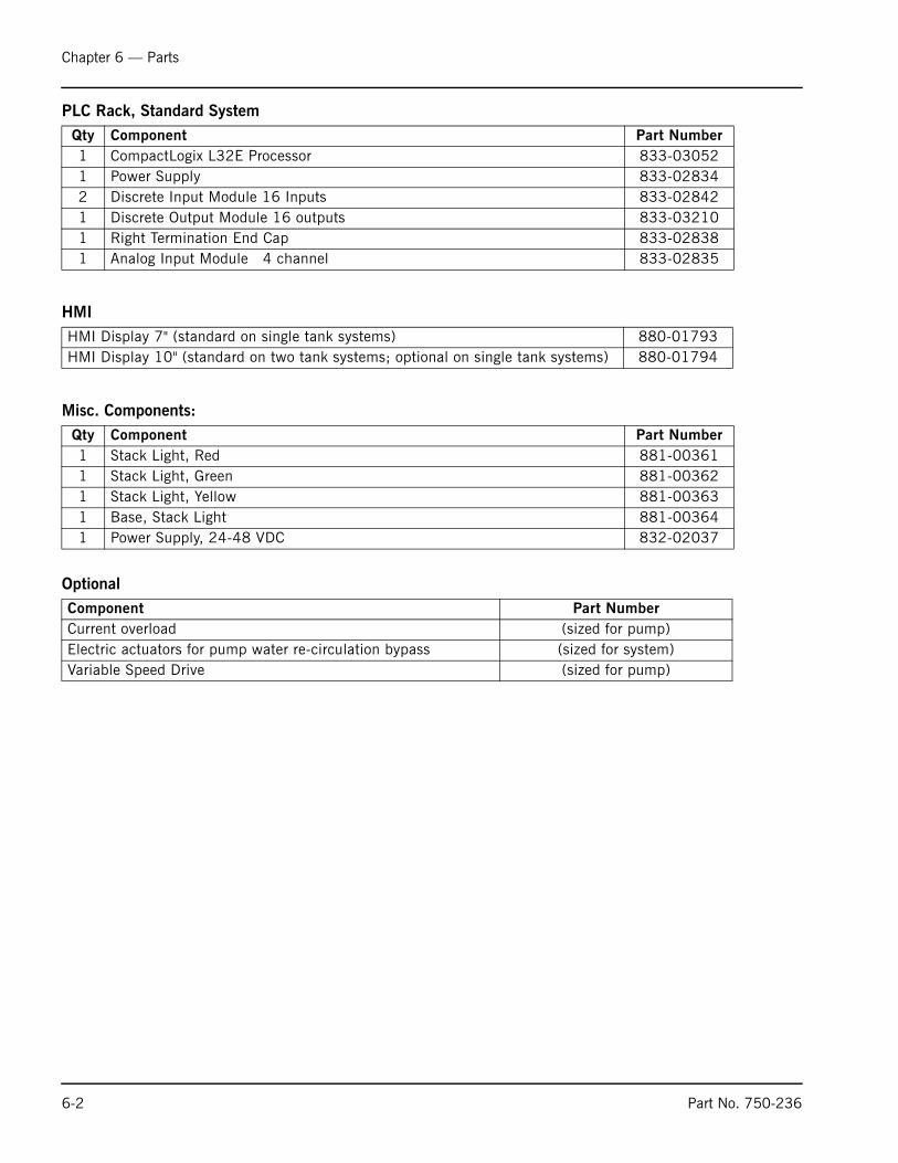
PLC Rack, Standard System
HMI
Misc. Components:
Optional
Qty Component Part Number1 CompactLogix L32E Processor 833-030521 Power Supply 833-028342 Discrete Input Module 16 Inputs 833-028421 Discrete Output Module 16 outputs 833-032101 Right Termination End Cap 833-028381 Analog Input Module 4 channel 833-02835
HMI Display 7" (standard on single tank systems) 880-01793HMI Display 10" (standard on two tank systems; optional on single tank systems) 880-01794
Qty Component Part Number1 Stack Light, Red 881-003611 Stack Light, Green 881-003621 Stack Light, Yellow 881-003631 Base, Stack Light 881-003641 Power Supply, 24-48 VDC 832-02037
Component Part NumberCurrent overload (sized for pump)Electric actuators for pump water re-circulation bypass (sized for system)Variable Speed Drive (sized for pump)

www.cleaverbrooks.com
Appendix
Supporting Documents/Reference DrawingsMagnetic Level Control Sizing Chart . . . . . . . . . . . . . . . . . . . . A-2Magnetic Level Control Installation Diagram . . . . . . . . . . . . . . . A-4DA Level Differential Pressure Transmitter Calibration . . . . . . . . A-5Differential Pressure Level Control . . . . . . . . . . . . . . . . . . . . . . A-6Differential Pressure Level Control/DA Tank Pressure Control . . . . A-7Single Tank I/O Card Layout . . . . . . . . . . . . . . . . . . . . . . . . . . A-9Dual Tank I/O Card Layout . . . . . . . . . . . . . . . . . . . . . . . . . . A-10Wiring Diagram . . . . . . . . . . . . . . . . . . . . . . . . . . . . . . . . . . A-11Control Panel Layout . . . . . . . . . . . . . . . . . . . . . . . . . . . . . . A-13DA Tank . . . . . . . . . . . . . . . . . . . . . . . . . . . . . . . . . . . . . . . A-14Surge Tank . . . . . . . . . . . . . . . . . . . . . . . . . . . . . . . . . . . . . A-15Duo-Tank . . . . . . . . . . . . . . . . . . . . . . . . . . . . . . . . . . . . . . A-16Alarm Piping . . . . . . . . . . . . . . . . . . . . . . . . . . . . . . . . . . . A-17Make-Up Valve . . . . . . . . . . . . . . . . . . . . . . . . . . . . . . . . . . A-18Gauge Glass . . . . . . . . . . . . . . . . . . . . . . . . . . . . . . . . . . . . A-21Pressure Reducing Valve . . . . . . . . . . . . . . . . . . . . . . . . . . . A-22Discharge Manifold . . . . . . . . . . . . . . . . . . . . . . . . . . . . . . . A-23Recirculation Piping . . . . . . . . . . . . . . . . . . . . . . . . . . . . . . A-24
NOTE: The following information is provided for reference pur-poses only. For detailed, up-to-date information on specific
installations, contact Cleaver-Brooks.

Magnetic Level Control Sizing Chart (1 of 2)
MODEL
High Water Alarm Location from bottom of
tank
Low Water Alarm Location from bottom of
tank
Low Water Cut-Off
Location from bottom of tank
Normal Water Level from
bottom of tank
Overflow Location from Bottom of tank
Distance Between High Water Alarm
and Low Water Cut-off
Distance Between
Overflow and Low Water Cut-
off
Suggested Gem Length
CB Part Number For
Gauge
CB Part Number for
xmtr
SPRAYMASTER 36" 26.50 9.50 7.50 21.00 28.00 19.00 20.50 29.00 881-365 817-4086 SPRAYMASTER 48" 21.00 9.00 7.00 15.00 24.00 14.00 17.00 29.00 881-365 817-4086 SPRAYMASTER 54" 28.00 14.00 12.00 19.00 31.00 16.00 19.00 29.00 881-365 817-4086 SPRAYMASTER 60" 34.00 15.00 13.00 25.00 37.00 21.00 24.00 29.00 881-365 817-4086 SPRAYMASTER 66" 34.50 16.50 14.50 25.50 39.50 20.00 25.00 29.00 881-365 817-4086 SPRAYMASTER 72" 41.00 18.00 16.00 32.00 44.00 25.00 28.00 29.00 881-365 817-4086 SPRAYMASTER 84" 53.00 21.00 19.00 44.00 56.50 34.00 37.50 48.00 881-366 817-4087 SPRAYMASTER 96" 70.00 24.00 22.00 61.00 74.50 48.00 52.50 59.00 881-376 817-4088 SPRAYMASTER 108" 77.00 27.00 25.00 68.00 81.50 52.00 56.50 59.00 881-376 817-4088
SURGE 36" 27.00 9.00 7.00 18.00 30.00 20.00 23.00 29.00 881-365 817-4086 SURGE 48" 36.00 12.00 10.00 24.00 39.00 26.00 29.00 29.00 881-365 817-4086 SURGE 54" 40.50 13.50 11.50 27.00 46.00 29.00 34.50 48.00 881-366 817-4087 SURGE 60" 45.00 15.00 13.00 30.00 50.50 32.00 37.50 48.00 881-366 817-4087 SURGE 66" 49.50 16.50 14.50 33.00 55.00 35.00 40.50 48.00 881-366 817-4087 SURGE 72" 54.00 18.00 16.00 36.00 61.50 38.00 45.50 48.00 881-366 817-4087 SURGE 84" 63.00 21.00 19.00 42.00 73.00 44.00 54.00 59.00 881-376 817-4088
BOILERMATE 24" 18.00 6.00 4.00 12.00 20.00 14.00 16.00 19.00 Call CallBOILERMATE 36" 30.00 12.00 10.00 24.00 32.00 20.00 22.00 29.00 881-365 817-4086 BOILERMATE 48" 42.00 18.00 16.00 34.00 44.00 26.00 28.00 29.00 881-365 817-4086 BOILERMATE 54" 39.00 26.00 28.00 31.00 50.00 11.00 22.00 29.00 881-365 817-4086 BOILERMATE 60" 54.00 15.00 13.00 45.00 56.00 41.00 43.00 48.00 881-366 817-4087
Signature DA 260 gallon 48" 19.19 9.00 6.00 16.06 25.56 13.19 19.56 29.00 881-365 817-4086 Signature DA 415 gallon 48" 19.25 8.88 6.00 14.38 25.88 13.25 19.88 29.00 881-365 817-4086 Signature DA 610 gallon 54" 24.06 11.19 6.00 18.00 31.44 18.06 25.44 29.00 881-365 817-4086 Signature DA 840 gallon 60" 28.75 13.31 6.00 21.44 37.44 22.75 31.44 48.00 881-366 817-4087 Signature DA 1105 gallon 33.38 13.38 6.00 24.81 43.88 27.38 37.88 48.00 881-366 817-4087 Signature DA 1400 gallon 37.75 17.31 6.00 28.00 49.81 31.75 43.81 48.00 881-366 817-4087 Signature DA 2485 gallon 45.81 20.88 6.00 33.81 60.25 39.81 54.25 59.00 881-376 817-4088

Magnetic Level Control Sizing Chart (2 of 2)
trol HWAControl Normal Water
Level Setpoint
3.25 17.750.00 14.001.00 12.003.50 14.502.00 13.005.50 16.509.25 30.251.25 42.253.25 44.25
3.00 14.006.00 14.005.75 22.257.25 22.258.75 22.259.25 21.256.50 25.50
5.50 9.503.50 17.506.50 18.504.50 6.503.50 34.50
7.91 14.787.81 12.949.84 13.781.03 23.722.44 23.883.84 24.092.19 30.19
MODELCenter of working range to
bottom of tankCenter of Gems Working Range
Control Lwco setpoint Control LWA Setpoint Con
SPRAYMASTER 36" 17.75 14.50 4.25 6.25 2 SPRAYMASTER 48" 15.50 14.50 6.00 8.00 2 SPRAYMASTER 54" 21.50 14.50 5.00 7.00 2 SPRAYMASTER 60" 25.00 14.50 2.50 4.50 2 SPRAYMASTER 66" 27.00 14.50 2.00 4.00 2 SPRAYMASTER 72" 30.00 14.50 0.50 2.50 2 SPRAYMASTER 84" 37.75 24.00 5.25 7.25 3 SPRAYMASTER 96" 48.25 29.50 3.25 5.25 5 SPRAYMASTER 108" 53.25 29.50 1.25 3.25 5
SURGE 36" 18.50 14.50 3.00 5.00 2 SURGE 48" 24.50 14.50 0.00 2.00 2 SURGE 54" 28.75 24.00 6.75 8.75 3 SURGE 60" 31.75 24.00 5.25 7.25 3 SURGE 66" 34.75 24.00 3.75 5.75 3 SURGE 72" 38.75 24.00 1.25 3.25 3 SURGE 84" 46.00 29.50 2.50 4.50 4
BOILERMATE 24" 12.00 9.50 1.50 3.50 1 BOILERMATE 36" 21.00 14.50 3.50 5.50 2 BOILERMATE 48" 30.00 14.50 0.50 2.50 2 BOILERMATE 54" 39.00 14.50 3.50 1.50 1 BOILERMATE 60" 34.50 24.00 2.50 4.50 4
Signature DA 260 gallon 48" 15.78 14.50 4.72 7.72 1 Signature DA 415 gallon 48" 15.94 14.50 4.56 7.44 1 Signature DA 610 gallon 54" 18.72 14.50 1.78 6.97 1 Signature DA 840 gallon 60" 21.72 24.00 8.28 15.59 3 Signature DA 1105 gallon 66" 24.94 24.00 5.06 12.44 3 Signature DA 1400 gallon 72" 27.91 24.00 2.09 13.41 3 Signature DA 2485 gallon 84" 33.13 29.50 2.38 17.25 4

Appendix
Magnetic Level Control Installation Diagram
GENERAL NOTES:
FIND CENTER OF TANK WORKING RANGE, 1/2 WAY BETWEENTHE OVERFLOW TO THE LOW WATER PUMP CUTOFF POINT.MOUNT THE GEMS MINI SURESITE SO THE CENTER POINT OFSENSOR IS MOUNTED AT THE CENTER POINT OF THE WORKINGRANGE OF THE TANK.
OVERFLOW
GEMS MINI SURESITE
HI WATER LEVEL
CENTER OF TANK
CENTER OF TANK WORKING RANGEIS CENTER OF GEMS TRANSMITTER RANGE
LOW WATER ALARM
LOW WATER PUMP CUTOFF
A-4 Part No. 750-236

Appendix
DA Level Differential Pressure Transmitter Calibration
Tank Diameter D Inches 24 36 48 54 60 66 72 84 96 108
Dimension B Inches 4 4 4 4 4 4 4 4 4 4
Transmitter Zero (4mA) -28 -40 -52 -58 -64 -70 -76 -88 -100 -112
Transmitter Span (20mA) -4 -4 -4 -4 -4 -4 -4 -4 -4 -4
Equations Used: dP(zero) = -(D+B) dP(span) = -B
Note: Dimension B is an estimate.
A
B
D
Transmitter
HighPress.Side
LowPress.Side
Part No. 750-236 A-5
Appendix
Differential Pressure Level Control
A-6 Part No. 750-236

Appendix
Differential Pressure Level Control and DA Tank Pressure Control (1 of 2)
Part No. 750-236 A-7

Appendix
Differential Pressure Level Control and DA Tank Pressure Control (2 of 2)
A-8 Part No. 750-236

Appendix
Single Tank I/O Card Layout
Part No. 750-236 A-9

Appendix
Dual Tank I/O Card Layout
A-10 Part No. 750-236

Appendix
Wiring Diagram (1 of 2)
Part No. 750-236 A-11

Appendix
Wiring Diagram (2 of 2)
A-12 Part No. 750-236

Appendix
Control Panel Layout
Part No. 750-236 A-13

Appendix
DA Tank
A-14 Part No. 750-236
Appendix
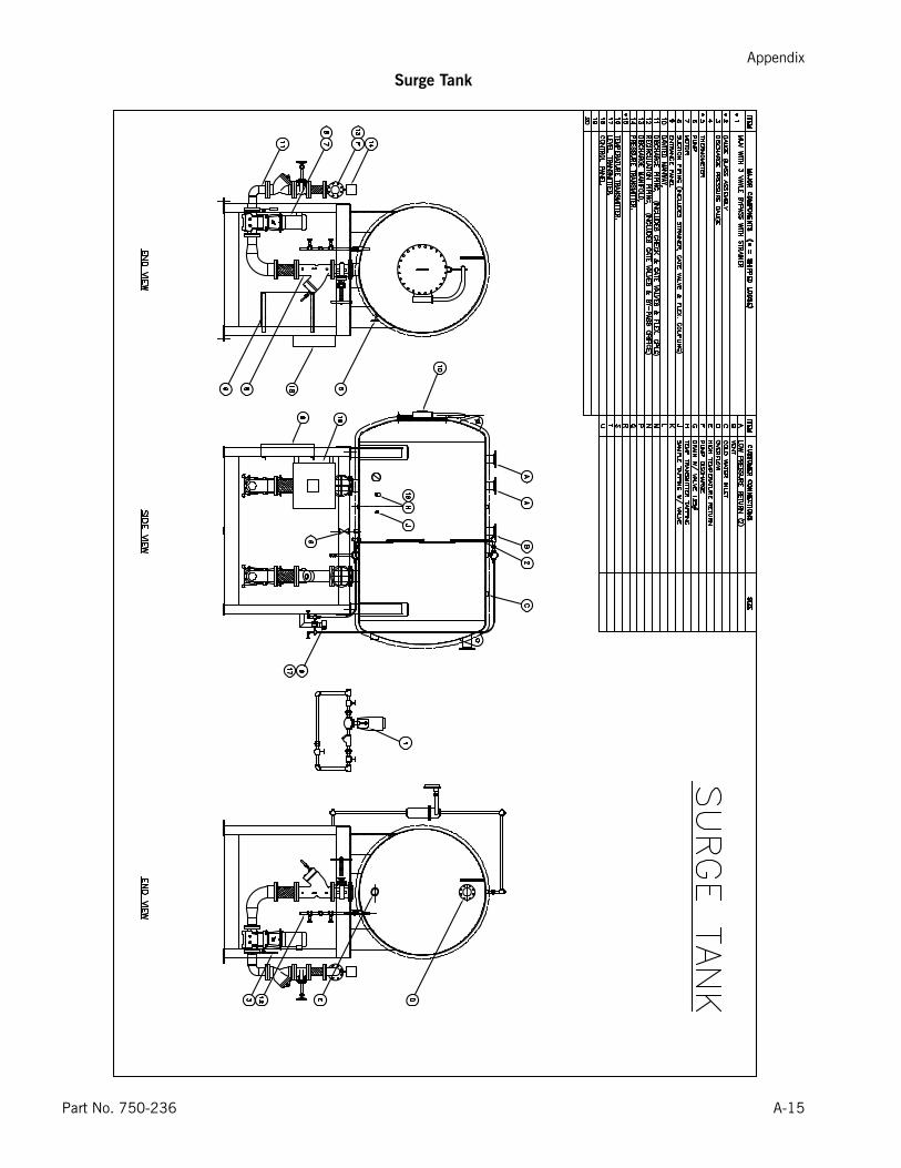
Surge Tank
Part No. 750-236 A-15

Appendix
Duo-Tank
A-16 Part No. 750-236

Appendix
Alarm Piping
Part No. 750-236 A-17

Appendix
Make-Up Valve (1 of 3)
A-18 Part No. 750-236
Appendix
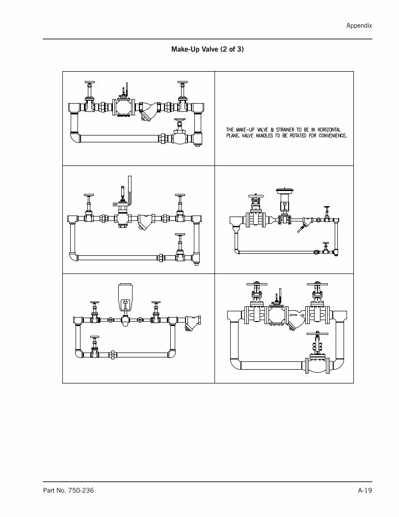
Make-Up Valve (2 of 3)
Part No. 750-236 A-19

Appendix
Make-Up Valve (3 of 3)
A-20 Part No. 750-236

Appendix
Gauge Glass
Part No. 750-236 A-21

Appendix
Pressure Reducing Valve
A-22 Part No. 750-236
Appendix
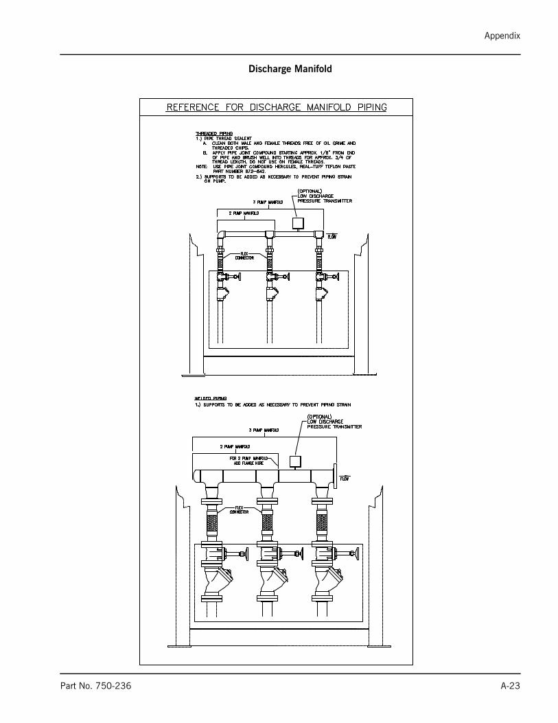
Discharge Manifold
Part No. 750-236 A-23

Appendix
Recirculation Piping
A-24 Part No. 750-236


e-mail: [email protected] Address: http://www.cleaverbrooks.com

![DEAERATOR - powerhx.com · DEAERATOR General [ Typical Deaerator Connections and Accessories ] Principle of deaerating Classification by Shape The removal of dissolved gases from](https://static.fdocuments.us/doc/165x107/5e0656589a5fbe7d5a551d58/deaerator-deaerator-general-typical-deaerator-connections-and-accessories-.jpg)