
ADT Trouble shooting - new1 - UCSB Nanofabrication...
25
-
Upload
nguyenngoc -
Category
Documents
-
view
213 -
download
0
Transcript of ADT Trouble shooting - new1 - UCSB Nanofabrication...

�

�
Dicing Troubleshooting
Contents:• Top Side chipping• Back side chipping • More chipping on one side of the kerf• Cracks on the die edge• Cut perpendicularly problems• Cuts are not straight• Kerf much wider than blade thickness• Dies are flying off the mounting media• Blade & flange set vibrating excessively• Burrs on substrates with soft metalizations• Too much blade wear• Excessive blade breakage• Saw gets into overloading

�
Top side chippingTop side chippingDecrease the diamond grit size:• Try uncoated diamonds [When using resin]
• Optimize the diamond concentration
• Try softer binders
– Freer cutting
– Higher wear
• Minimize vibrations
– Dynamically balance the flange/blade
on the saw
– Optimize the spindle RPM
• Improve the mounting to eliminate die
movement
• Optimize the exposure left
• Adjust the coolant pressure and align the
nozzle flow

• Use the hardest tape to minimize loading [UV-Polyester].
• Use thinner tape for better tape flexibility• Optimize the handling & curing when using
PVC type tapes• If possible use a wax/glue type mounting• Optimize the feed rate / spindle RPM• Dress the blade to minimize loading
• Add additives to the coolant to lower the
surface tension of the coolant
• Optimize the diamond concentration to
minimize the blade edge radius
• Use a higher wear bond to minimize loading
Back Side ChippingBack Side Chipping• Maintain a min. cut depth of .001” into the tape
Min. .001”Adhesive

�
• Use the thinnest blade possible to
minimize the radius on the blade edge
Top side
Back side
Back Side Chipping
Cont.

�
Back Side ChippingBack Side Chipping
• Adjust the cooling nozzle and minimize the flow to reduce blade vibrations
Cont.

�
More chipping on one side of the kerf
In order to define the cause of side chipping dismount the blade and remount it at 180°in the flange, If chipping remains on same side then :
• Adjust the cooling nozzle• When dicing on tape, optimize
the mounting handling to minimize die movement
• Change to a UV tape (stronger adhesion)
• Check the spindle alignment to the X movement

�
. Reject
Cracks on the die edgeCracks on the die edge
• Use a larger diamond grit (to minimize loads)
• Use a more wearing type blade (softer matrix)
• When using resin blades, optimize the diamond type - coated / uncoated.
• Lower the diamond concentration to minimize loading
• To minimize loads, redress the blade to expose new sharp diamonds
OK

�
Cracks on the die edgeCracks on the die edge
• Use a two step cut
• Optimize the mounting method / material to
minimize blade overloading
• Optimize the coolant alignment and flow
• Lower the feed rate to minimize loading
• Optimize the spindle RPM
• Minimize blade vibrations
. RejectOK
�
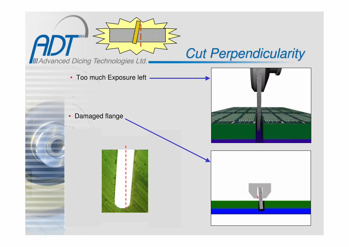
Cut PerpendicularityCut Perpendicularity
• Too much Exposure left
• Damaged flange

��
Cut PerpendicularityCut Perpendicularity
• High ratio of exposure to blade thickness
– Check the option of using a thicker blade
– Reduce feed rate and / or increase the RPM
– Add additives to the coolant
• Optimize the blade to minimize loads:
– Use a Lower diamond concentration
– Optimize the diamond size
– Lapped blades will minimize side friction
– Use serrated blades to minimize the loading
• Improve the mounting method
• Adjust the cooling nozzle & the coolant flowCont.

��
Cuts are not straightCuts are not straight
• High ratio of exposure to blade thickness• Too much load:
– Reduce feed rate and / or increase RPM– Use larger diamonds if possible.– Add additives to the coolant
• Diamonds are too large on thin blades [not enough binder]
• Damaged flange
• Too much exposure left

��
• Check for any flange defects
• Check and optimize the mounting to eliminate any die
movement
• Check for any defects on the blade edge and on the
side surfaces
KerfKerf wider than blade thicknesswider than blade thickness
• Check the 90 °degree alignment of the
spindle to the table [X] movement.
• Check Wheel mount Axial run - out

�
Kerf wider than blade thickness
• Try a higher RPM for better blade stiffness
• Slow down the feed rate to minimize the load• Add coolant additives to minimize the load
• Optimize the coolant flow for :
– Better blade & substrate cooling
– Blade vibrations
– Die movement
Cont.

��
Dies are flying off the Dies are flying off the mounting mediamounting media
Optimize the mounting:
• Use glue or wax if possible
• When using blue tape, optimize the curing
• Use a harder tape with stronger adhesive (UV-type)
• Slow down the spindle RPM
• Lower the feed rate
• Adjust the cooling flow and pressure

��
Blade & Flange SetBlade & Flange Set--Excessively VibratingExcessively Vibrating
• Loose blade I.D. can cause vibrations
• Check for defects on the spindle wheel mount
• Run the spindle without the flange set
• Clean the spindle and the flange parts and
reassemble
• Check for defects on the back side flange
• Check the flange for loose parts
• Try different RPM’s (harmonic vibrations varies
on different saws)

��
Burrs on Substrates with Burrs on Substrates with Soft MetallizationSoft Metallization
• Back side burrs: try a harder tape or if possible change
to wax or glue mounting
• Optimize the coolant to minimize loads
• On resinoid blades use lapped blades to minimize load
• Try the resinoid special side grooved blades
• Optimize the spindle speed and feed rate - Lowering the
feed rate will minimize the load and the burrs.
• Add coolant additive

��
Excessive blade wearExcessive blade wear• Optimize the blade matrix: • Use a larger diamond grit
Use a harder blade matrixUse a higher diamond concentrationOptimize the diamond typeIf possible, use a thicker bladeIf possible, try a serrated or side grooved blade
• Optimize the mounting media• Optimize the spindle RPM & the feed rate
– Higher RPM acts like a harder blade – matrix– Higher feed rate increases loading – and wear
• Optimize the coolant:– Align the cooling nozzle– Optimize the cooling flow– Add additives, if possible– On deep cuts try a high cooling – flange

��
Uneven Blade Wear
� Adjust the coolant Pressure and align the nozzle flow� Dismount the blade and remount it at 180°in the flange. If the
uneven wear becomes a mirror picture than change the blade.� Check for Y-Offset (Dicing is not in the middle of the street).� Try a softer blade (higher wear) to reduce the load.� Check the spindle alignment to the X movement

�
Excessive Blade BreakageExcessive Blade Breakage
• Check the flange condition
• Maintain a min. cut depth of .001” into the tape
min. into the tape
• Minimize the exposure left
• Check the saw slide movements [X,Y]
• Try a lower Diamond conc. to minimize loads
• Use a thicker blade if possible
• Optimize the mounting to minimize vibration
and blade loading
• Optimize the coolant
• Optimize the cutting parameters to minimize
loads

��
9.00
Saw gets into Saw gets into OverloadingOverloading
• Dress the blade to expose new diamonds
which will minimize loading
• Use a higher RPM for higher spindle torque
• Lower the feed rate
• Use a blade with a larger diamond grit
• Use a blade with lower diamond concentration
• Use a softer blade binder
– Higher wear
– Less load
• Make multiple cuts

��
Protrusion on Package Singulation - BGA
500 �m
500 �m
500 �m
Protrusion thickness – 0.006 -.0010mm

��
A remaining lipdue to load anddevice movement
Second index
Device movement at the end of the dice line
(In extreme cases not only at the end of the dice line)
Spindle
Vacuum tray movement
Protrusion
Single device
Protrusion on Package Singulation - BGA

�
Options to Eliminate /Minimize the Protrusion
� Slow down the feed rate on the second index at the exit of the cut. � Improve drastically the device vacuum clamping during the dicing.
This is a key issue.� Improve the flatness of the device clamping area in
order to minimize any vacuum lose.� Adjust the cooling nozzle & pressure. A too much pressure may "help" the
device to move and loose its clamping.� Make sure your spindle is perfectly aligned (90 degree) to the X
movement. If not perfectly 90 degree it can cause a wider cut andside forces that may move the device. See the attached Video (Double Click)

��
� Use a more wearing type blade to minimize the load. ADT has many different options to explore this option.
Second Index – “steps” dicing to minimize die movement:
Spindle
Step # 1
Spindle
Step # 2 & 3
1
2
3
Spindle
Step # 4,5,6 & 7
4
5
6
7
Options to Eliminate / Minimize the Protrusion


![3M NEW1[1]](https://static.fdocuments.us/doc/165x107/577cd91b1a28ab9e78a2b674/3m-new11.jpg)


