ADSR Systems - the Reactor Tony Roulstone 13 April 2010.
23
ADSR Systems - the Reactor Tony Roulstone 13 April 2010
-
Upload
myrtle-charles -
Category
Documents
-
view
218 -
download
0
Transcript of ADSR Systems - the Reactor Tony Roulstone 13 April 2010.
ADSR Systems - the Reactor
Tony Roulstone
13 April 2010
Contents
• Challenge of the ADSR proposal 3
• System considerations 5
• Reactor Concept Studies 6
– Carlo Rubbia - Aker Solutions 7
– Weinberg - Molten Salt 9
– LFR - Ceballos 10
– MYRRHA 11
– ELSY/LEADER 13
• Some Key Design Issues 15
• ADSR Reactor Strategy 21
• Reactor Work Programme Requirements 22
2
Challenge of the ADSR proposal
• ‘Towards an Alternative Nuclear Future’ is a substantial and impressive piece of work on both the ADSR system and on the accelerator elements - which are both key to bringing the ADSR concept to reality;
• ADSR could provide the opportunity for UK to lead in a new and large industry – utilising Thorium for electrical power;
• The aim is show that an ADSR system at commercial scale, and on the timescale of 2025, is an ‘entirely feasible and achievable’ objective - if adequate R&D is undertaken now;
• The level of definition of the accelerator plan and hence its technology development is at a fuller level than the reactor;
• ThorEA should develop a matching conceptual R&D strategy and work plan for the reactor:
– Collaboration and/or reference designs;
– System considerations;
– Key design issues.
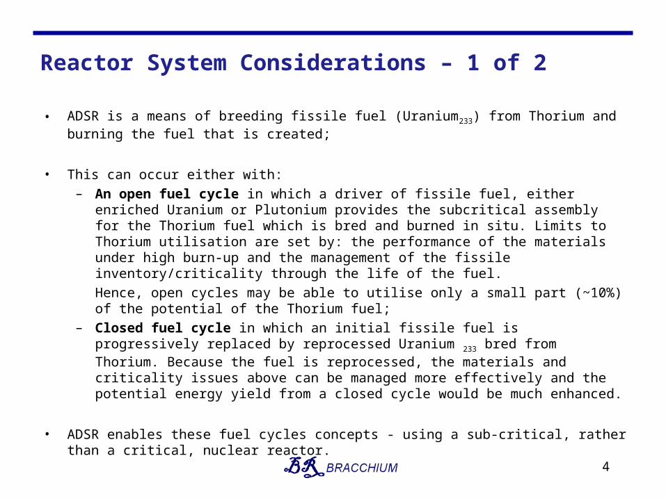
Reactor System Considerations – 1 of 2
• ADSR is a means of breeding fissile fuel (Uranium233) from Thorium and burning the fuel that is created;
• This can occur either with: – An open fuel cycle in which a driver of fissile fuel, either enriched Uranium or
Plutonium provides the subcritical assembly for the Thorium fuel which is bred and burned in situ. Limits to Thorium utilisation are set by: the performance of the materials under high burn-up and the management of the fissile inventory/criticality through the life of the fuel.
Hence, open cycles may be able to utilise only a small part (~10%) of the potential of the Thorium fuel;
– Closed fuel cycle in which an initial fissile fuel is progressively replaced by reprocessed Uranium 233 bred from Thorium. Because the fuel is reprocessed, the materials and criticality issues above can be managed more effectively and the potential energy yield from a closed cycle would be much enhanced.
• ADSR enables these fuel cycles concepts - using a sub-critical, rather than a critical, nuclear reactor.
4
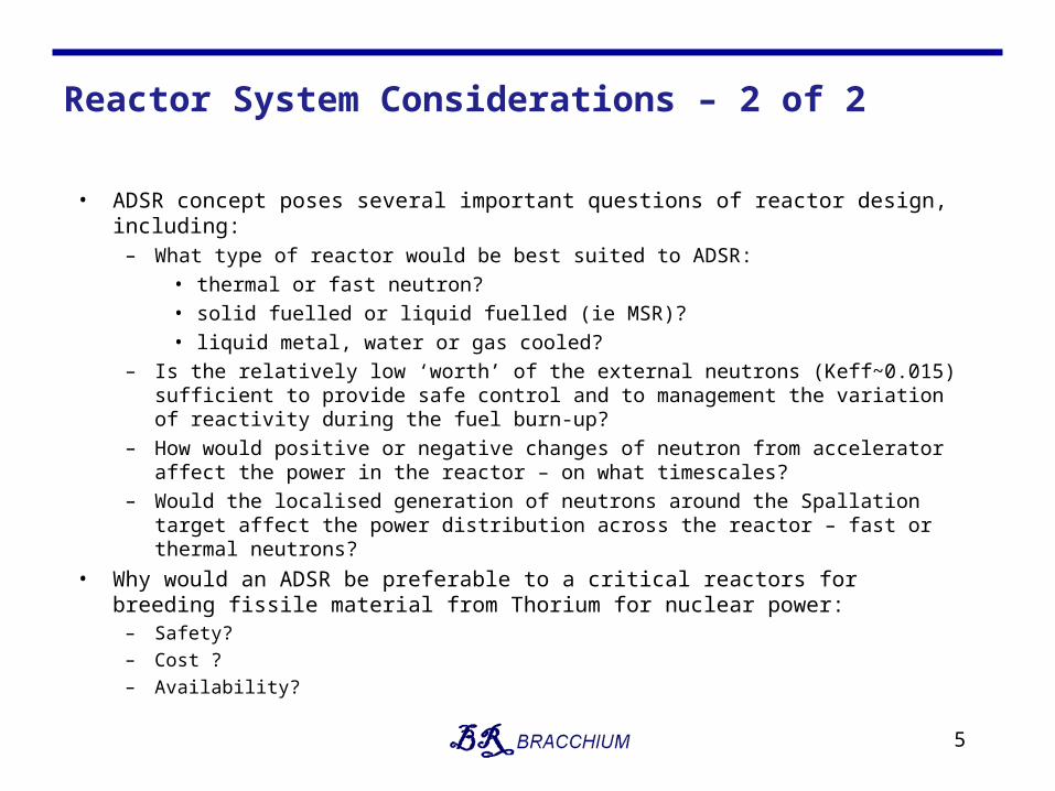
Reactor System Considerations – 2 of 2
• ADSR concept poses several important questions of reactor design, including:– What type of reactor would be best suited to ADSR:
• thermal or fast neutron?• solid fuelled or liquid fuelled (ie MSR)?• liquid metal, water or gas cooled?
– Is the relatively low ‘worth’ of the external neutrons (Keff~0.015) sufficient to provide safe control and to management the variation of reactivity during the fuel burn-up?
– How would positive or negative changes of neutron from accelerator affect the power in the reactor – on what timescales?
– Would the localised generation of neutrons around the Spallation target affect the power distribution across the reactor – fast or thermal neutrons?
• Why would an ADSR be preferable to a critical reactors for breeding fissile material from Thorium for nuclear power:
– Safety?
– Cost ?
– Availability?
5
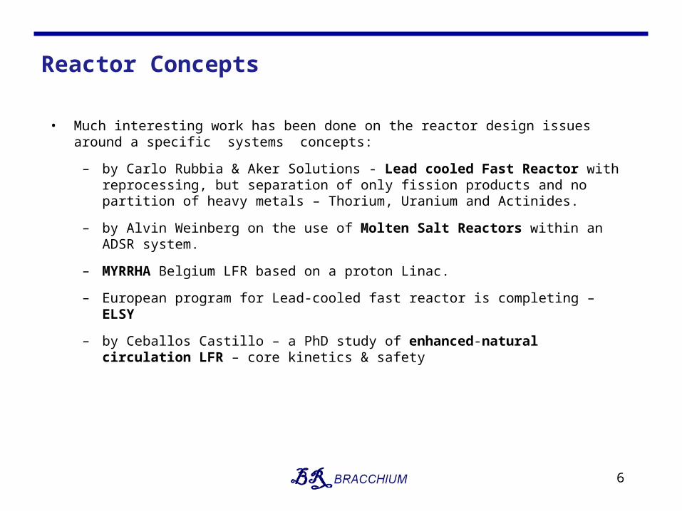
Reactor Concepts
• Much interesting work has been done on the reactor design issues around a specific systems concepts:
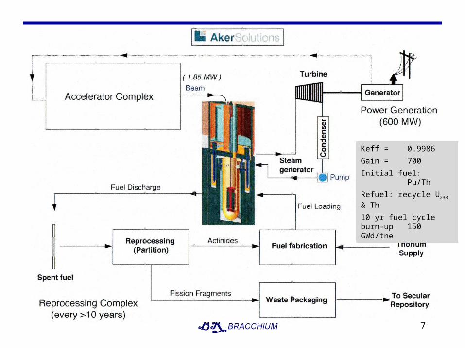
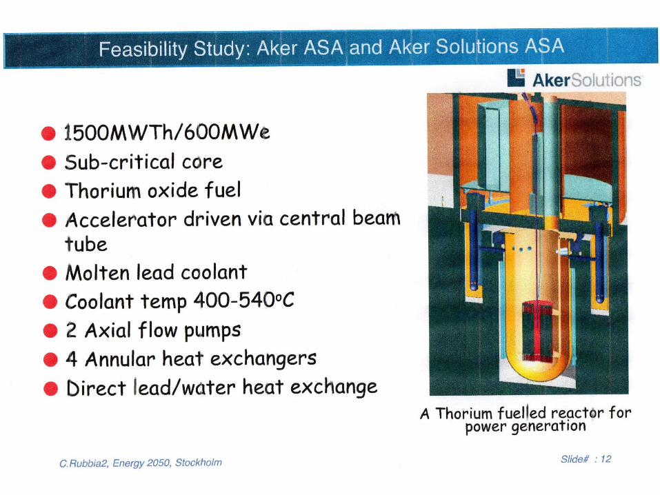
– by Carlo Rubbia & Aker Solutions - Lead cooled Fast Reactor with reprocessing, but separation of only fission products and no partition of heavy metals – Thorium, Uranium and Actinides.
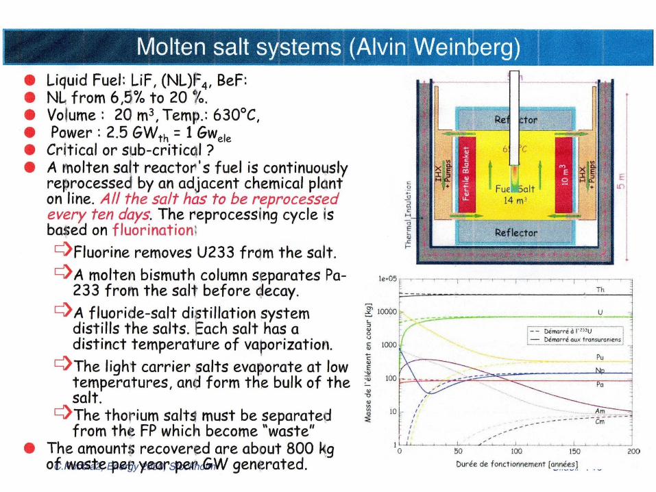
– by Alvin Weinberg on the use of Molten Salt Reactors within an ADSR system.
– MYRRHA Belgium LFR based on a proton Linac.
– European program for Lead-cooled fast reactor is completing – ELSY
– by Ceballos Castillo – a PhD study of enhanced-natural circulation LFR – core kinetics & safety
6
7
Keff = 0.9986
Gain = 700
Initial fuel: Pu/Th
Refuel: recycle U233 & Th
10 yr fuel cycle burn-up 150 GWd/tne
8
9
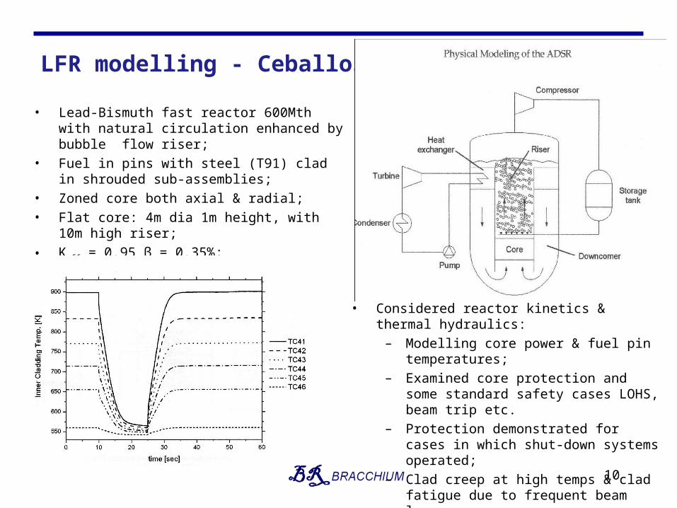
LFR modelling - Ceballos
10
• Lead-Bismuth fast reactor 600Mth with natural circulation enhanced by bubble flow riser;
• Fuel in pins with steel (T91) clad in shrouded sub-assemblies;
• Zoned core both axial & radial;
• Flat core: 4m dia 1m height, with 10m high riser;
• Keff = 0.95 β = 0.35%;
• Conventional steam cooling/power cycle.
• Considered reactor kinetics & thermal hydraulics:
– Modelling core power & fuel pin temperatures;
– Examined core protection and some standard safety cases LOHS, beam trip etc.
– Protection demonstrated for cases in which shut-down systems operated;
– Clad creep at high temps & clad fatigue due to frequent beam loss.
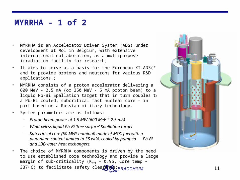
MYRRHA - 1 of 2
• MYRRHA is an Accelerator Driven System (ADS) under development at Mol in Belgium, with extensive international collaboration, as a multipurpose irradiation facility for research;
• It aims to serve as a basis for the European XT-ADS(*) and to provide protons and neutrons for various R&D applications.;
• MYRRHA consists of a proton accelerator delivering a 600 MeV - 2.5 mA (or 350 MeV - 5 mA proton beam) to a liquid Pb-Bi Spallation target that in turn couples to a Pb-Bi cooled, subcritical fast nuclear core – in part based on a Russian military technology.
• System parameters are as follows:
– Proton beam power of 1.5 MW (600 MeV * 2.5 mA)
– Windowless liquid Pb-Bi ‘free surface’ Spallation target
– Sub-critical core (60 MWt nominal) made of MOX fuel with a plutonium content limited to 35 wt%, cooled by pumped Pb-Bi and LBE-water heat exchangers.
• The choice of MYRRHA components is driven by the need to use established core technology and provide a large margin of sub-criticality (Keff = 0.95, Core temp – 337o C) to facilitate safety clearance;
11
MYRRHA - 2 of 2
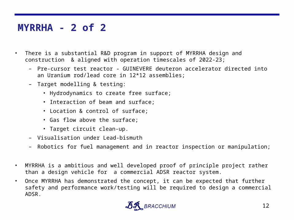
• There is a substantial R&D program in support of MYRRHA design and construction & aligned with operation timescales of 2022-23;
– Pre-cursor test reactor - GUINEVERE deuteron accelerator directed into an Uranium rod/lead core in 12*12 assemblies;
– Target modelling & testing:
• Hydrodynamics to create free surface;
• Interaction of beam and surface;
• Location & control of surface;
• Gas flow above the surface;
• Target circuit clean-up.
– Visualisation under Lead-bismuth
– Robotics for fuel management and in reactor inspection or manipulation;
• MYRRHA is a ambitious and well developed proof of principle project rather than a design vehicle for a commercial ADSR reactor system.
• Once MYRRHA has demonstrated the concept, it can be expected that further safety and performance work/testing will be required to design a commercial ADSR.
12
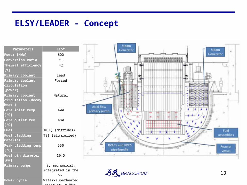
ELSY/LEADER - Concept
13
Parameters ELSY
Power [MWe] 600
Conversion Ratio ~1
Thermal efficiency [%] 42
Primary coolant Lead
Primary coolant circulation (power)
Forced
Primary coolant circulation (decay heat )
Natural
Core inlet temp [°C] 400
Core outlet tem [°C] 480
Fuel MOX, (Nitrides)
Fuel cladding material T91 (aluminized)
Peak cladding temp [°C] 550
Fuel pin diameter [mm] 10.5
Primary pumps 8, mechanical,integrated in the SG
Power Cycle Water-superheated steam at 18 MPa, 450°C
Primary/secondary heat transfer system
Eight Pb-to-H2O SGs
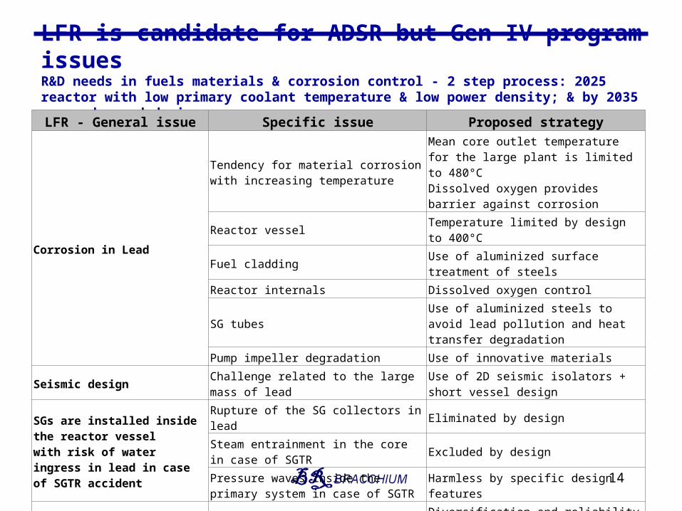
LFR is candidate for ADSR but Gen IV program issuesR&D needs in fuels materials & corrosion control - 2 step process: 2025 reactor with low primary coolant temperature & low power density; & by 2035 more advanced designs.
14
LFR - General issue Specific issue Proposed strategy
Corrosion in Lead
Tendency for material corrosion with increasing temperature
Mean core outlet temperature for the large plant is limited to 480°CDissolved oxygen provides barrier against corrosion
Reactor vessel Temperature limited by design to 400°C
Fuel cladding Use of aluminized surface treatment of steels
Reactor internals Dissolved oxygen control
SG tubesUse of aluminized steels to avoid lead pollution and heat transfer degradation
Pump impeller degradation Use of innovative materials
Seismic design Challenge related to the large mass of leadUse of 2D seismic isolators + short vessel design
SGs are installed inside the reactor vessel with risk of water ingress in lead in case of SGTR accident
Rupture of the SG collectors in lead Eliminated by design
Steam entrainment in the core in case of SGTR Excluded by design
Pressure waves inside the primary system in case of SGTR
Harmless by specific design features
DHRDiversification, reliability and passive operation required
Diversification and reliability by means of use of both atmospheric air and stored water
Refuelling in lead High temperature makes refuelling difficult Access to fuel assemblies is in cold cover gas
Key Design Issues
15
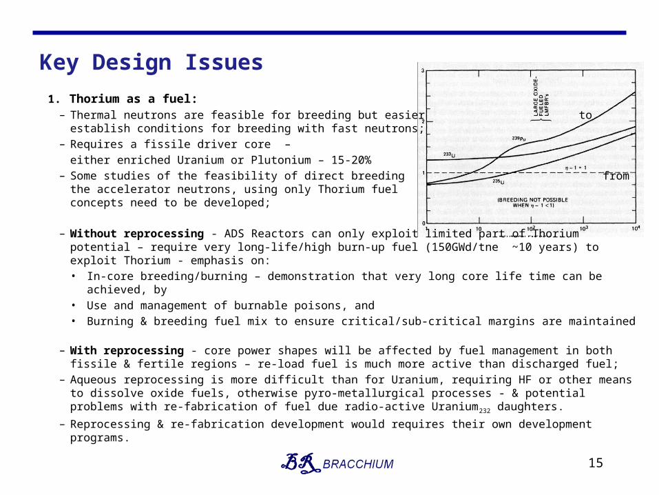
1. Thorium as a fuel:– Thermal neutrons are feasible for breeding but easier to
establish conditions for breeding with fast neutrons;– Requires a fissile driver core –
either enriched Uranium or Plutonium – 15-20%– Some studies of the feasibility of direct breeding
from the accelerator neutrons, using only Thorium fuel concepts need to be developed;
– Without reprocessing - ADS Reactors can only exploit limited part of Thorium potential – require very long-life/high burn-up fuel (150GWd/tne ~10 years) to exploit Thorium - emphasis on: • In-core breeding/burning – demonstration that very long core life time can be achieved, by• Use and management of burnable poisons, and• Burning & breeding fuel mix to ensure critical/sub-critical margins are maintained
– With reprocessing - core power shapes will be affected by fuel management in both fissile & fertile regions – re-load fuel is much more active than discharged fuel;
– Aqueous reprocessing is more difficult than for Uranium, requiring HF or other means to dissolve oxide fuels, otherwise pyro-metallurgical processes - & potential problems with re-fabrication of fuel due radio-active Uranium232 daughters.
– Reprocessing & re-fabrication development would requires their own development programs.
Key Design Issues
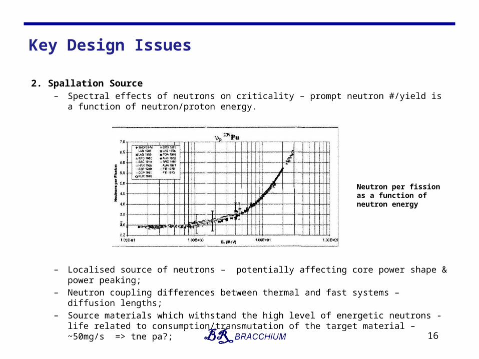
2. Spallation Source– Spectral effects of neutrons on criticality – prompt neutron #/yield is a function of
neutron/proton energy.
– Localised source of neutrons – potentially affecting core power shape & power peaking;– Neutron coupling differences between thermal and fast systems – diffusion lengths;– Source materials which withstand the high level of energetic neutrons - life related to
consumption/transmutation of the target material – ~50mg/s => tne pa?;
16
Neutron per fission as a function of neutron energy
Key Design Issues
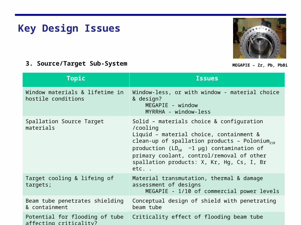
3. Source/Target Sub-System
17
Topic Issues
Window materials & lifetime in hostile conditions
Window-less, or with window - material choice & design? MEGAPIE - window MYRRHA - window-less
Spallation Source Target materials Solid – materials choice & configuration /coolingLiquid – material choice, containment & clean-up of spallation products – Polonium210 production (LD50 ~1 μg) contamination of primary coolant, control/removal of other spallation products: X, Kr, Hg, Cs, I, Br etc. .
Target cooling & lifeing of targets; Material transmutation, thermal & damage assessment of designs MEGAPIE - 1/10 of commercial power levels
Beam tube penetrates shielding & containment
Conceptual design of shield with penetrating beam tube
Potential for flooding of tube affecting criticality?
Criticality effect of flooding beam tube
MEGAPIE – Zr, Pb, PbBi
Key Design Issues
4. Reactivity Control
• Through-life:– Either accelerator must be capable of providing neutrons for ΔK/K at EOL ~ 9% and is
modulated during operation, or – Complex fuel management/shuffling/breeding together with burnable poisons to manage
reactivity with the aim ΔK/K at SOL ~ ΔK/K at EOL, or– Control rods provide macro control of reactivity & accelerator has fixed neutrons capacity.
Reactivity safety may appear to be little different from a conservatively-designed conventional/ critical reactor;
18
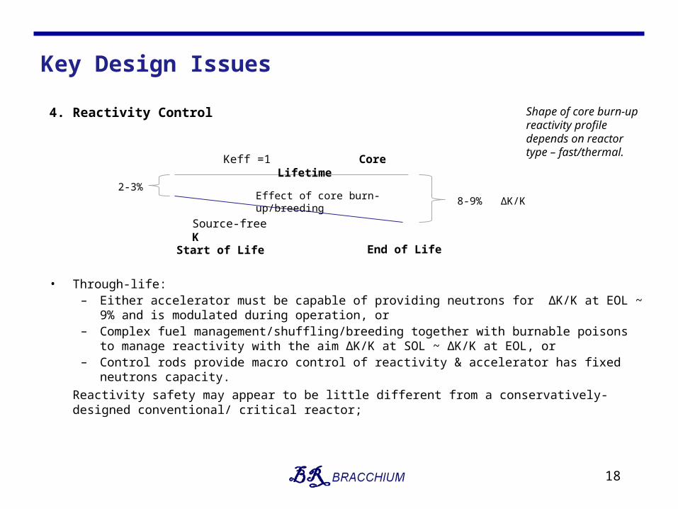
Keff =1 Core Lifetime
Start of Life End of Life
Effect of core burn-up/breeding2-3%
8-9% ΔK/K
Source-free K
Shape of core burn-up reactivity profile depends on reactor type – fast/thermal.
Key Design Issues
4. Reactivity Control(cont’d)
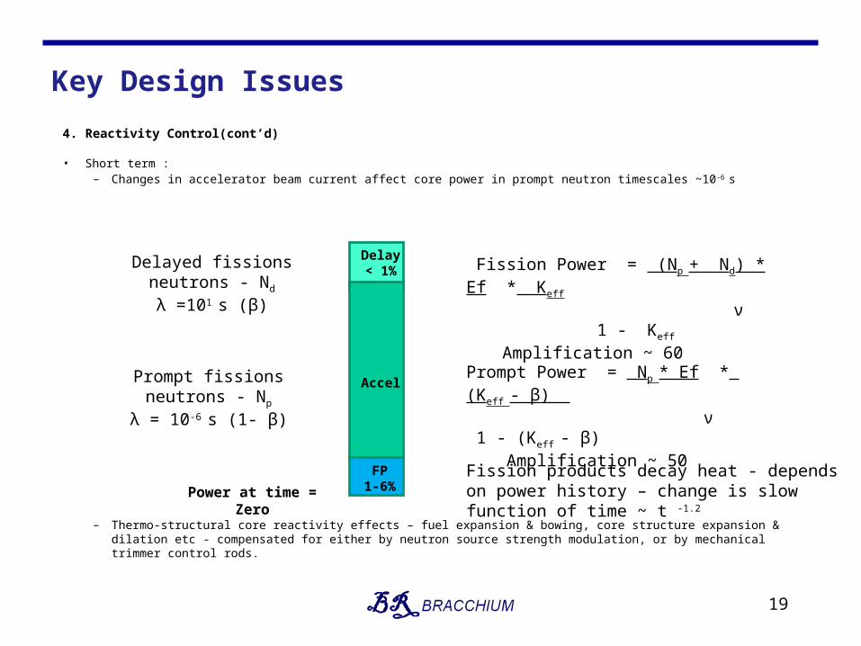
• Short term :– Changes in accelerator beam current affect core power in prompt neutron timescales ~10 -6 s
– Thermo-structural core reactivity effects – fuel expansion & bowing, core structure expansion & dilation etc - compensated for either by neutron source strength modulation, or by mechanical trimmer control rods.
19
Prompt fissions neutrons - Np
λ = 10-6 s (1- β)
Delayed fissions neutrons - Nd
λ =101 s (β)
Fission products decay heat - depends on power history – change is slow function of time ~ t -1.2
Prompt Power = Np * Ef * (Keff - β)
ν 1 - (Keff - β) Amplification ~ 50
Fission Power = (Np + Nd) * Ef * Keff
ν 1 - Keff
Amplification ~ 60
Power at time = Zero
FP1-6%
Delay< 1%
Accel
Key Design Issues
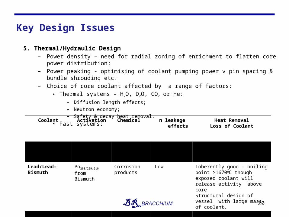
5. Thermal/Hydraulic Design– Power density – need for radial zoning of enrichment to flatten core power distribution;– Power peaking - optimising of coolant pumping power v pin spacing & bundle shrouding etc.– Choice of core coolant affected by a range of factors:
• Thermal systems – H2O, D2O, CO2 or He:– Diffusion length effects;– Neutron economy;– Safety & decay heat removal.
• Fast systems:
20
Coolant Activation Chemical n leakage effects
Heat RemovalLoss of Coolant
Gas: He/CO2 None Low Steam +ve void coefficient
High PressureDecay heat after leak?
Lead/Lead-Bismuth
Po208/209/210 from Bismuth
Corrosion products
Low Inherently good - boiling point >1670oC though exposed coolant will release activity above coreStructural design of vessel with large mass of coolant.
Sodium Na24 Sodium water reactions
Phase change +ve void coefficient
Low likelihood of vessel breeching – Sodium burns in air activation products.
ADSR Reactor Strategy
• Current reactor systems concepts, are informative, but:
– Have substantial technological risks and hence similarly long development timescale as other Generation IV reactors;
– Will require many £bn of development/demonstration programs before they become ready for commercialisation.
• To support the claim that a commercial ADSR is an ‘entirely feasible and achievable’ objective - ThorEA either has, or should have, a work program that;
– Addresses the key technical design issues, and – Produces a concept or reference design which makes the Reactor proposal clear.
• Scale of challenge is large - therefore need to make choices about systems & collaboration:
1. Join in the EU work of MYRRHA/LEADER in support of fast reactor development;2. Develop a distinctive fast reactor ADSR proposal;3. Investigate feasibility of thermal ADSR – light, heavy water, gas cooled.
• Map out a collaborative work program, that provides impetus to the concept in the UK.
21
Reactor Development Work Program
• Technology/Components:1. Thorium as a fuel – including the Fuel Cycle technology;2. Spallation Source;3. Source Sub-system;4. Reactivity Control;5. Thermal-hydraulic Design;6. Materials R&D needs/means – Spallation Source & Reactor.
• System Concept:– System studies that identify the preferred design configuration;– General arrangement layout of reference design;– Fuel Cycle flow sheet;– Preliminary assessment of design against NII SAPs & outline PSA;
• Development Program:– Outline schedule for technology, component/systems demonstrator and the approach to
commercialisation;– Identification of technological and development major risks;– RoM Development, Capital & Operating costs.
22

Endwww.bracchium.net
23


![Proactive Highly Ambulatory Sensor Routing (PHASeR ... · T.Hayes,F.H.Ali/PervasiveandMobileComputing21(2015)47–61 49 Angle-basedDynamicSourceRouting(ADSR)[25]usestheanglebetweenpotentialforwardingneighboursandthesink](https://static.fdocuments.us/doc/165x107/5f0405797e708231d40bed6b/proactive-highly-ambulatory-sensor-routing-phaser-thayesfhalipervasiveandmobilecomputing21201547a61.jpg)