ADSP-2189M EZ-KIT Lite Evaluation System...
45
ADSP-2181 EZ-KIT Lite Evaluation System Manual Revised: January 2001 Part Number 82-000543-01 a
Transcript of ADSP-2189M EZ-KIT Lite Evaluation System...

ADSP-2181 EZ-KIT LiteEvaluation System Manual
Revised: January 2001
Part Number82-000543-01
aaaa

ADSP-2181 EZ-KIT Lite Evaluation System Manual ii
NoticeAnalog Devices, Inc. reserves the right to make changes to or to discontinue any product or service identified in thispublication without notice.
Analog Devices assumes no liability for Analog Devices applications assistance, customer product design, customersoftware performance, or infringement of patents or services described herein. In addition, Analog Devices shall notbe held liable for special, collateral, incidental or consequential damages in connection with or arising out of thefurnishing, performance, or use of this product.
Analog Devices products are not intended for use in life-support applications, devices, or systems. Use of an AnalogDevices product in such applications without the written consent of the Analog Devices officer is prohibited.Users are restricted from copying, modifying, distributing, reverse engineering, and reverse assembling or reversecompiling the ADSP-2181 EZ-KIT Lite operational software (one copy may be made for back-up purposes only).No part of this document may be reproduced in any form without permission.
Trademark and Service Mark Notice
The Analog Devices logo, SHARC, the SHARC logo, VisualDSP, the VisualDSP logo, and EZ-ICE are registeredtrademarks; and TigerSHARC, the TigerSHARC logo, White Mountain DSP, VisualDSP++, the VisualDSP++ logo,Apex-ICE, EZ-KIT Lite, Mountain-ICE, Summit-ICE, Trek-ICE, and The DSP Collaborative are trademarks ofAnalog Devices, Inc.
Microsoft and Windows are registered trademarks and Windows NT is a trademark of Microsoft Corporation.
Adobe and Acrobat are trademarks of Adobe Systems Incorporated.
All other brand and product names are trademarks or service marks of their respective owners.
Limited WarrantyThe ADSP-2181 EZ-KIT Lite hardware is warranted against defects in materials and workmanship for a period ofone year from the date of purchase from Analog Devices or from an authorized dealer.
Copyright © 2001, Analog Devices, Inc. All rights reserved.Rev 1, January 2001
82-000543-01

ADSP-2181 EZ-KIT Lite Evaluation System Manual iii
TABLE OF CONTENTS
1 INTRODUCTION.................................................................................................................................................... 7
1.1 FOR MORE INFORMATION ABOUT ANALOG PRODUCTS ....................................................................................... 81.2 FOR TECHNICAL OR CUSTOMER SUPPORT............................................................................................................ 81.3 PURPOSE OF THIS MANUAL.................................................................................................................................. 81.4 INTENDED AUDIENCE........................................................................................................................................... 81.5 MANUAL CONTENTS DESCRIPTION ...................................................................................................................... 81.6 DOCUMENTATION AND RELATED PRODUCTS ....................................................................................................... 91.7 CONVENTIONS ..................................................................................................................................................... 9
2 GETTING STARTED ........................................................................................................................................... 10
2.1 OVERVIEW......................................................................................................................................................... 102.2 CONTENTS OF YOUR EZ-KIT LITE PACKAGE .................................................................................................... 102.3 INSTALLATION PROCEDURES ............................................................................................................................. 10
2.3.1 Installing The EZ-KIT Lite Board ............................................................................................................. 112.3.2 Installing VisualDSP.................................................................................................................................. 11
2.3.2.1 System Requirements.............................................................................................................................................112.3.2.2 To Install the Software ...........................................................................................................................................122.3.2.3 To Install the License.............................................................................................................................................122.3.2.4 To Register the Product .........................................................................................................................................132.3.2.5 To View the Documentation ..................................................................................................................................13
2.3.3 Installing the EZ-KIT Lite Software .......................................................................................................... 132.3.3.1 Default Settings......................................................................................................................................................13
3 USING EZ-KIT LITE SOFTWARE .................................................................................................................... 14
3.1 OVERVIEW......................................................................................................................................................... 143.2 STANDARD OPERATION...................................................................................................................................... 14
3.2.1 I/O Devices ................................................................................................................................................ 143.2.1.1 Flags.......................................................................................................................................................................143.2.1.2 Interrupts................................................................................................................................................................143.2.1.3 Serial Ports.............................................................................................................................................................15
3.2.2 POST Routines........................................................................................................................................... 153.2.2.1 Memory Checks .....................................................................................................................................................153.2.2.2 UART Check/Initialization ....................................................................................................................................163.2.2.3 AD1847 Check/Initialization .................................................................................................................................16
3.2.3 Monitor Program Operation....................................................................................................................... 163.2.3.1 Breakpoints ............................................................................................................................................................17
3.2.4 AD1847 Transmissions .............................................................................................................................. 173.3 RUNNING YOUR OWN PROGRAMS ..................................................................................................................... 18
3.3.1 ADSP-2181 Memory Map ......................................................................................................................... 183.3.2 Using the AD1847 Dual Analog Front End ............................................................................................... 19
4 DEMONSTRATION PROGRAMS ..................................................................................................................... 20
4.1 OVERVIEW......................................................................................................................................................... 204.2 STARTING THE VISUALDSP DEBUGGER............................................................................................................. 20
4.2.1 Debugger Operation with the ADSP-2181 EZ-KIT Lite............................................................................ 214.2.1.1 Loading Programs..................................................................................................................................................214.2.1.2 Registers and Memory ...........................................................................................................................................22
ADSP-2181 EZ-KIT Lite Evaluation System Manual iv
4.2.1.3 Setting Breakpoints and Stepping ..........................................................................................................................224.2.1.4 Resetting the EZ-KIT Lite Board...........................................................................................................................22
4.3 DEMONSTRATION PROGRAMS............................................................................................................................ 224.3.1 ADPCM.dxe............................................................................................................................................... 234.3.2 DTMF.dxe.................................................................................................................................................. 234.3.3 ECHO.dxe.................................................................................................................................................. 234.3.4 Primes70.dxe.............................................................................................................................................. 234.3.5 FIRDEMO.dxe........................................................................................................................................... 234.3.6 LPC2K4.dxe............................................................................................................................................... 244.3.7 LPC7K8.dxe............................................................................................................................................... 24
4.4 REFERENCE........................................................................................................................................................ 244.4.1 Settings Menu Commands.......................................................................................................................... 24
4.4.1.1 Baud Rate...............................................................................................................................................................254.4.1.2 Comm Port .............................................................................................................................................................25
5 WORKING WITH EZ-KIT LITE HARDWARE............................................................................................... 26
5.1 OVERVIEW......................................................................................................................................................... 265.2 EZ-KIT LITE SPECIFICATIONS ........................................................................................................................... 265.3 SYSTEM ARCHITECTURE .................................................................................................................................... 275.4 BOARD LAYOUT................................................................................................................................................. 28
5.4.1 Socketed Memory ...................................................................................................................................... 285.4.2 User LEDs.................................................................................................................................................. 285.4.3 Switches ..................................................................................................................................................... 295.4.4 Power Connector........................................................................................................................................ 295.4.5 European Power Supply Specifications...................................................................................................... 295.4.6 AD1847 Connections ................................................................................................................................. 305.4.7 Expansion Port Connectors ........................................................................................................................ 305.4.8 Connectors and Headers............................................................................................................................. 305.4.9 EZ-ICE Connector ..................................................................................................................................... 31
5.5 DESIGNING AN EZ-ICE COMPATIBLE TARGET................................................................................................... 335.5.1 Hardware Debugging ................................................................................................................................. 34
5.6 EXPANSION CONNECTORS.................................................................................................................................. 34
APPENDIX A RESTRICTIONS ............................................................................................................................. 36
APPENDIX B BILL OF MATERIALS .................................................................................................................. 37
APPENDIX C SCHEMATICS ................................................................................................................................ 38
ADSP-2181 EZ-KIT Lite Evaluation System Manual v
LIST OF TABLES
TABLE 2-1 SYSTEM REQUIREMENTS........................................................................................................................... 12TABLE 2-2 USER CONFIGURABLE EZ-KIT LITE SETTINGS........................................................................................... 13TABLE 3-1 POST ROUTINES......................................................................................................................................... 15TABLE 3-2 MEMORY MAP .......................................................................................................................................... 19TABLE 5-1 POWER CONNECTION ................................................................................................................................ 29TABLE 5-2 EUROPEAN POWER SUPPLY SPECIFICATIONS............................................................................................. 29TABLE 5-3 ADSP-2181 PIN NAMES ........................................................................................................................... 35
ADSP-2181 EZ-KIT Lite Evaluation System Manual vi
LIST OF FIGURES
FIGURE 4-1 TARGET SELECTION DIALOG.................................................................................................................... 20FIGURE 4-2 TARGET MESSAGE ................................................................................................................................... 21FIGURE 4-3 SETTINGS MENU COMMANDS .................................................................................................................. 24FIGURE 5-1 EZ-KIT LITE SYSTEM BLOCK DIAGRAM ................................................................................................. 27FIGURE 5-2 EZ-KIT LITE BOARD LAYOUT................................................................................................................. 28FIGURE 5-3 JP2 JUMPER SETTINGS ............................................................................................................................. 31FIGURE 5-4 JP2 JUMPER SETTINGS ............................................................................................................................. 31FIGURE 5-5 JP1 JUMPER SETTING FOR 27C256 EPROM............................................................................................. 32FIGURE 5-6 JP1 JUMPER SETTINGS FOR 21C512/27C010 EPROM ............................................................................. 32FIGURE 5-7 JP1 JUMPER SETTINGS FOR 27C020/27C040/ 27C080 EPROM............................................................... 32FIGURE 5-8 EZ-ICE 14-PIN HEADER (P6) .................................................................................................................. 33FIGURE 5-9 EXPANSION CONNECTOR ......................................................................................................................... 34

ADSP-2181 EZ-KIT Lite Evaluation System Manual 7
Thank you for purchasing the ADSP-2181 EZ-KIT LiteTM evaluation kit. The evaluation board is designed tobe used in conjunction with VisualDSP® and the 16-bit tools as a complete code evaluation and debug system.This product is shipped with the VisualDSP integrated development environment (IDE) and debugger whichcontains the code generation tools (C compiler, linker, and assembler). Using the EZ-KIT Lite with thedebugger, you can observe the ADSP-2181 execute programs from on-chip RAM, interact with on-boarddevices, and communicate with other peripherals located on optional add-on modules.
You can access the ADSP-2181 processor from the PC through a serial port or an optional emulator. Themonitor program gives you complete target debug capability through the serial port. In contrast, the emulatorallows the PC to perform in-circuit emulation through the processor�s emulation port.
The board�s features include:
• ADSP-2181, 33 MIPS DSP
• AD1847 stereo codec
• RS-232 interface
• Socketed EPROM
• User push buttons
• Power supply regulation
• Expansion connectors
• User configurable jumper
The EZ-KIT Lite board is equipped with hardware that facilitates interactive demonstrations. Push buttonswitches and user programmable LEDs provide user control and board status. Additionally, the AD1847SoundPort codec provides access to an audio input (selectable as line level or microphone) and an audio output(line level).
The EZ-KIT Lite includes a monitor program stored in the socketed EPROM. The monitor program lets theboard communicate over the serial port to a PC. This monitor program lets you download, execute and debugADSP-2181 programs.
You can also connect an EZ-ICE (in-circuit emulator) to the EZ-KIT Lite. Through the EZ-ICE, you can loadprograms, start and stop program execution, observe and alter registers and memory, and perform otherdebugging operations. The EZ-ICE emulator is available from Analog Devices.
Additionally, the EZ-KIT Lite provides user installed expansion connectors that let you examine processorsignals, as well as provide an interface for host control.
1 INTRODUCTION
ADSP-2181 EZ-KIT Lite Evaluation System Manual 8
1.1 For More Information About Analog ProductsAnalog Devices is accessible on the Internet at www.analog.com. The DSP web page is directlyaccessible at www.analog.com/dsp. This page provides access to DSP specific technical information anddocumentation, product overviews, and product announcements.
1.2 For Technical or Customer Support You can reach our Customer Support group in the following ways:
• Email questions to [email protected]
• Contact your local Analog Devices sales office or an authorized Analog Devices distributor
1.3 Purpose of This ManualThe ADSP-2181 EZ-KIT Lite evaluation system manual gives directions for installing the board andsoftware, and using the demonstration programs on your PC. Also, this manual provides guidelines forrunning your own code on the ADSP-2181.
1.4 Intended AudienceThis manual is a user�s guide and reference to the ADSP-2181 EZ-KIT Lite evaluation board. DSPprogrammers who are familiar with Analog Devices 16-bit architecture, operation, and programming arethe primary audience for this manual.
DSP programmers who are unfamiliar with Analog Devices DSPs can use this manual, but shouldsupplement this manual with the ADSP-2100 Family User�s Manual and the VisualDSP tools manuals.
1.5 Manual Contents DescriptionThis manual contains the following information:
• Chapter 2 � Getting Started
Provides software and hardware installation procedures, PC system requirements, and basic board information.
• Chapter 3 � Using EZ-KIT Lite software
Provides information on the EZ-KIT Lite system from a software perspective, and details the monitor program and codec.
• Chapter 4 � Demonstration Programs
Provides information on the demonstration programs that ship with your EZ-KIT Lite and VisualDSP Debugger reference information.
• Chapter 5 � Working With EZ-KIT Lite Hardware

ADSP-2181 EZ-KIT Lite Evaluation System Manual 9
Provides information on the Hardware aspects of the evaluation system and on the connectors to the ADSP-2181 interface and AD1847 pins.
• Appendix A � Restrictions
Provides information on board restrictions you may encounter when using your EZ-KIT Lite.
• Appendix B � Bill of Materials
Provides a list of components used in the manufacture of the EZ-KIT Lite board.
• Appendix C � Schematics
1.6 Documentation and Related ProductsFor more information on the ADSP-2181 and the components of the EZ-KIT Lite system, see thefollowing documents:
• ADSP-2100 Family User�s Manual
• ADSP-2181 DSP Microcomputer data sheet
• AD1847 General Purpose Analog Front End data sheet
The ADSP-218x family of processors is supported by a complete set of development tools. Software toolsinclude a C compiler, assembler, runtime libraries and librarian, linker, simulator, and PROM splitter.These tools are described in the following texts:
• VisualDSP User�s Guide for the ADSP-21xx Family DSPs
• C Compiler & Library Manual for the ADSP-218x Family DSPs
• Assembler Manual for ADSP-218x Family DSPs
• Linker and Utilities Manual for ADSP-21xx Family DSPs
• Product Bulletin for VisualDSP and the ADSP-218x Family DSPs
These documents are found on the Analog Devices� Technical Documentation web site at:www.analog.com/industry/dsp/tech_doc/gen_purpose.html.
If you plan to use the EZ-KIT Lite in conjunction with the EZ-ICE emulator, refer to the documentationthat accompanies that product.
1.7 ConventionsThe following conventions are used throughout this manual:
• The ! graphic indicates restrictions and warnings.
• The " graphic indicates important information.

ADSP-2181 EZ-KIT Lite Evaluation System Manual 10
2.1 OverviewThis chapter provides you with the information you need to install your software and the ADSP-2181evaluation board. It is important that you install your software and hardware in the order presented forcorrect operation.
2.2 Contents of Your EZ-KIT Lite Package
The EZ-KIT Lite evaluation board contains ESD (electrostaticdischarge) sensitive devices. Electrostatic charges readily accumulateon the human body and equipment and can discharge withoutdetection. Permanent damage may occur on devices subjected to highenergy discharges. Proper ESD precautions are recommended to avoidperformance degradation or loss of functionality. Unused EZ-KITLites should be stored in the protective shipping package.
Your ADSP-2181 EZ-KIT Lite evaluation package contains the following items. If any item is missing,contact the vendor where you purchased your EZ-KIT Lite or Analog Devices.
• ADSP-2181 EZ-KIT Lite board
• Power cable with 8-10V DC power supply
• RS-232 serial port 9-pin cable
• One CD ROM, containing the EZ-KIT Lite examples, target .dll files, and utilities
• One CD ROM, containing the VisualDSP software
• One CD ROM, containing the DSP Designer�s Reference
2.3 Installation Procedures
The following procedures are provided for the safe and effective use of the ADSP-2181 evaluation board.It is important that you follow these instructions in the order presented to ensure correct operation of yoursoftware and hardware. After you have completed the physical set up of your board, you can load and runthe demonstration programs contained on the distribution media. For more information, see Chapter 4Demonstration Programs.
2 GETTING STARTED

ADSP-2181 EZ-KIT Lite Evaluation System Manual 11
2.3.1 Installing The EZ-KIT Lite Board
The ADSP-2181 EZ-KIT Lite board is designed to run outside your personal computer as a stand-alone unit. You do not have to remove the chassis from your computer. Use the following steps toconnect the EZ-KIT Lite board:
1. Remove the EZ-KIT Lite board from the package�be careful when handling theseboards to avoid the discharge of static electricity, which may damage some components.
2. Connect the RS-232 cable to an available Comm Port on the PC and to J3 on theADSP-2181 evaluation board.
3. Plug the provided cord into a 120-Volt AC receptacle and plug the connector at the otherend of the cable into J4 on the evaluation board.
All of the LEDs light up briefly. The power (green) LED remains on and FL1 blinks. If the LEDdoes not light up, check the power connections.
To configure your board to take advantage of the audio capabilities of the demos, use the followingprocedure:
1. Plug a set of self-powered computer speakers into jack J1 on the board. Turn on thespeakers and set the volume to an adequate level.
2. Connect the line out of an electronic audio device to jack J2 on the board. Set jumper JP2to LINE.
3. Open Jumper JP2 to GND to enable the AD1847 codec. (This is the board default).
This completes the hardware installation. For complete information on the EZ-KIT Lite board, see�Board Layout�.
2.3.2 Installing VisualDSP
Your EZ-KIT Lite comes with the latest version of VisualDSP for ADSP-218x Family DSPs. Youmust install this software prior to installing the EZ-KIT Lite software.
2.3.2.1 System Requirements
Verify your PC has the minimum requirements.

ADSP-2181 EZ-KIT Lite Evaluation System Manual 12
Table 2-1 System Requirements
Windows® 95, 98, ME, 2000 Windows NTTM
Windows 95, 98, ME, 2000 Windows NT 4.0, Service Pack 3 or laterPentium processor 166MHz or faster Pentium processor 166MHz or faster100 MB available space 100 MB available space16 MB RAM 16 MB RAMVGA Monitor and color video card VGA Monitor and color video cardCD-ROM CD-ROMCOMCTL32.DLL, 4.71 COMCTL32.DLL, 4.71COMCAT.DLL, 4.71 COMCAT.DLL, 4.71
The installation requires that you have COMCTL32.DLL 4.71 installed. You can check yourversion with the find utility, right click on the file, select Properties, then select Version. If you donot have version 4.71, you must run COM32UPD.EXE. You can find COM32UPD.EXE byselecting your CD-ROM drive, selecting ADI and double clicking on COM32UPD.EXE.
The installation recommends version 4.71 or greater of COMCAT.DLL. If the installation detects aversion older that 4.71, it prompts you to replace the current version of COMCAT.DLL.
2.3.2.2 To Install the Software
1. From the initial screen, select Install VisualDSP.
2. Install the VisualDSP software by responding to the installation dialog screens.
3. Re-boot the computer once you have finished the installation.
2.3.2.3 To Install the License
You need to supply the serial number provided on the sticker affixed to the CD case.
1. From the initial screen, select Install License.
2. Then select single user license.
3. Install the license by responding to the installation dialogs.
This installs a permanent limited license.
This is a limited license. This license lets you run EZ-KIT Lite sessions only. Simulation andemulation are not supported. For a full license, contact your local Analog Devices Salesrepresentative.

ADSP-2181 EZ-KIT Lite Evaluation System Manual 13
2.3.2.4 To Register the Product
You can fax your registration card to (603) 882-2655 or mail it to:
Analog Devices, Inc.20 Cotton RdNashua NH, 03063Attn: Registration
Please note that the VisualDSP software that comes with your EZ-KIT Lite is a demo version thatlimits executable file size to 8K bytes. The EZ-KIT Lite board is also the only target you canattach to. You may upgrade your license by contacting your local Analog Devices salesrepresentative.
2.3.2.5 To View the Documentation
To view documentation on-line, you must have a .pdf reader installed. The Adobe ®Acrobat®
installation kit has been included on the CD-ROM for your convenience. To install Adobe AcrobatReader, click Adobe Acrobat Reader in the initial screen and respond to the dialog boxes asprompted.
2.3.3 Installing the EZ-KIT Lite Software
The EZ-KIT Lite utility software is supplied on one CD-ROM. To install the EZ-KIT Litesoftware, follow these steps:
1. Close all VisualDSP and Windows applications.
2. You cannot install any of the EZ-KIT Lite software if any VisualDSP applications are running. You should close all Windows applications also.
3. Install the VisualDSP software by responding to the installation dialog screens. 4. Re-boot the computer once you have finished the installation.
2.3.3.1 Default Settings
After you have installed the board and utility software, your PC and EZ-KIT Lite have the defaultsettings shown in Table 2-2. You can change these settings through the Settings menu in thedebugger.
Table 2-2 User Configurable EZ-KIT Lite SettingsSelection Default SettingComm Port Comm 1Baud Rate 9600

ADSP-2181 EZ-KIT Lite Evaluation System Manual 14
3.1 Overview
The combination of the EZ-KIT Lite board and the monitor software operate as a target for theVisualDSP debugger. The debugger lets you view processor registers and memory and perform severaldebugging activities, such as setting breakpoints, stepping through code, and plotting a range of memory.
3.2 Standard Operation
This section covers the standard operation of the EZ-KIT Lite board. It describes the I/O capabilities ofthe on-board components, board power-up, and the on-board Monitor program.
3.2.1 I/O Devices
3.2.1.1 Flags
The ADSP-2181 has one asynchronous FLAG I/O pin. Pin (FL1) is connected to the red FL1 LED.This lets you visually inspect states of your program.
3.2.1.2 Interrupts
The ADSP-2181 EZ-KIT Lite has one external interrupt connected through push button switch S2.This corresponds to external interrupt IRQE.
The external interrupts are controlled through the ICNTL and IMASK registers and are configuredby modifying the interrupt vector table or through instructions in user code. The ICNTL registeralso controls the interrupt sensitivity between level and edge. To prevent an interrupt from beingmasked, write to the IMASK register.
The monitor program running on the ADSP-2181 uses one interrupt (the timer) for normaloperation. When downloading your own code through the monitor program, the timer interruptvector is protected and cannot be overwritten. If these vectors are overwritten, or the timerinterrupt is masked in any way, the debugger will not be able to communicate with the hostprogram. The following rules and restrictions should be followed when using interrupts:
• You cannot step into an interrupt.
• Interrupts are disabled when the user program is halted.
3 USING EZ-KIT LITE SOFTWARE

ADSP-2181 EZ-KIT Lite Evaluation System Manual 15
• The board cannot communicate with the host if interrupt nesting is enabled.
• If you do not require the supplied monitor program, a start-up routine that dynamicallyalters the timer interrupt vector can be used. This removes all monitor functionality.
3.2.1.3 Serial Ports
The ADSP-2181 features two synchronous bi-directional Serial Ports (SPORTs). The SPORTs canoperate at up to 1x clock frequency, providing each with a maximum data rate of 30 Mbit/sec.SPORT data can be automatically transferred to and from on-chip memory using DMA.
SPORT0 is connected to the on-board AD1847. The CODECDIS signal available on connector P3can be used to disable the codec. When this signal is brought low, the codec is disabled and itssignals are put in a high impedance state. SPORT1 is connected to the RS-232 interface and isused as a software UART. Communications between the monitor and the host are throughSPORT1.
For more information on the Serial Ports, see the ADSP-2100 Family User�s Manual.
3.2.2 POST Routines
POST (Power On Self-Test) routines are a series of standard tests and initializations that the EZ-KIT Lite performs on a power-on reset. To perform a power-on reset, disconnect power to theboard for at least three seconds and then reconnect power. The board automatically resets (notethat all the LED�s light up briefly). You may also reset the board during operation through theDebug, Reset command in the debugger. Both types of reset cause the DSP to reset to a knownstate. At this point you should reload any programs you were working on. Table 3-1 shows thetypes of resets and their functions
Table 3-1 Post Routines
Routine Power-on Reset Reset During OperationEPROM Load Yes NoAD1847 Check Yes NoInitializations Yes Yes
3.2.2.1 Memory Checks
The monitor program performs some standard memory checks which are as follows:
1. EPROM
2. Internal RAM
ADSP-2181 EZ-KIT Lite Evaluation System Manual 16
The EPROM test consists of verifying a number in memory. If the monitor code is corrupted, themonitor may crash before reaching the actual program code.
3.2.2.2 UART Check/Initialization
The software UART check is done when it attempts to connect to the EZ-KIT Lite through aTransmitted Loop Back routine. This UART test is performed by the host after the POST iscomplete. In this test, the host sends the UART test protocol. This protocol specifies the number ofbytes that are transmitted to the EZ-KIT Lite board, and instructs the board to echo the byte streamback to the host. This test determines whether the EZ-KIT Lite board is set to the correct baud rate,and verifies the external connections between the board and the host.
On power up, the EZ-KIT Lite board defaults to a baud rate of 9600 baud with 8 data bits, 1 stopbit, and no parity. To change this rate wait for the POST routine to complete and then use theSettings, Baud Rate command in the debugger. Note that setting the baud rate to a lower numbercan significantly slow the board�s response to all debug activities.
Different baud rates should be selected based on the type of code you are working with. For real-time interrupt driven programs, a lower baud rate setting slows performance but the timer interruptoccurs less frequently. This gives your program a larger share of the processors resources.
3.2.2.3 AD1847 Check/Initialization
On reset, the AD1847 is inactive. An initialization routine initializes the codec by sending a seriesof command words through the SPORT0 TX interrupt. Once the commands have been sent and theAD1847 is initialized, it begins transmitting the clock which synchronizes data transfers to & fromthe DSP. Once this bit goes high, the AD1847 is ready for standard communication over SPORT0.
3.2.3 Monitor Program OperationThe monitor program runs on the EZ-KIT Lite board as part of the DSP executable, and providesthe ability to download, debug, and run user programs. The VisualDSP debugger is the interfacefor the monitor. Using the EZ-KIT Lite as a target with the debugger lets you operate the boardremotely.
There are three main components of the monitor program:
• Halt loop
• UART ISR (Timer ISR)
• Command Processing Kernel
The monitor program idles in the Halt loop when it is not running user code. While there, you canread/write memory, read/write registers, download programs, set breakpoints, change the UART�sbaud rate, and single step through code. To enter the halt loop from your code, you must suspendor stop user code�either with a breakpoint or a halt instruction. At this point, the halt loop pollsthe UART. With every character received from the UART, the command-processing kernelverifies whether a full command has been received. If a command has been received, the kernel

ADSP-2181 EZ-KIT Lite Evaluation System Manual 17
processes the command; otherwise control is returned to the halt loop to wait for more characters.The only method of executing your code once the halt loop has been entered is to send a Run orSingle Step command in the debugger.
The UART ISR is entered when your code is running, but the host is still interacting with theboard. As the host sends bytes, the UART ISR takes the data stream from the UART, and buildsthe command. As with the halt loop, each character received is passed to the command-processingkernel. Unlike the halt loop, the monitor returns to your code immediately after the interrupt isserviced.
The following restrictions should be followed to ensure correct board operation.
! The host loses contact with the monitor while the user program is running if the user programdisables the Timer interrupt or changes the Timer interrupt vector.
! The host loses contact with the monitor while the program is running and it enters anInterrupt Service Routine when nesting is turned on.
" The host cannot halt with the debugger�s Debug, Halt command if global IRQ enable isdisabled (ena ints/ dis ints bit). However, breakpoints will work.
" The debugger will have trouble halting at a baud rate over 9600 while using the monitorprogram.
Command processing, initiated from either the UART ISR or the Halt Loop, is done in thecommand-processing kernel. This kernel parses the commands and executes the instructions. If theinstruction requires data to be sent back to the host, the kernel initiates the response.
3.2.3.1 BreakpointsThe ability to stop the execution of code and examine processor registers and memory is extremelyhelpful when debugging code. Note that the debugger automatically inserts breakpoints at thefunction Main(), when the Settings, Run To Main command is checked, and at the _exitinstruction.
3.2.4 AD1847 Transmissions
After initialization, the AD1847 generates the clock used to transfer data across SPORT0. TheADSP-2181 initiates all transmissions with the AD1847 by sending a synchronization pulse. Eventhough the AD1847 transmits the data clock, it may not be ready for normal operation.
Initialization of the AD1847 is performed by sending 13 control words contained in a circularbuffer to the AD1847. This is usually done via the SPORT0 TX interrupt routine. Once the codecis initialized, autobuffering is used to fill up the TX and RX buffers, which use circular buffering.Once the circular buffer wraps around, then either a TX or RX interrupt occurs. Then the DSP willprocess the interrupt request.
ADSP-2181 EZ-KIT Lite Evaluation System Manual 18
3.3 Running Your Own Programs
This section provides you with the basic information you need to run your own programs on the ADSP-2181 EZ-KIT Lite. You build these programs using the 16-bit tools. This information includes rules forusing processor memory and a simple program generation procedure.
Although there are many ways to go about developing programs in the VisualDSP environment, allprogram development within the environment should include the following steps:
• Step1: Create a New Project File
• Step 2: Set Target Processor Project Options
• Step 3: Add and Edit Project Source Files
• Step 4: Customize Project Build Options
• Step 5: Build a Debug Version of the Project
• Step 6: Debug the Project
• Step 7: Build a Release Version of the Project
By following these steps, your DSP projects build consistently and accurately with minimal projectmanagement. Note the following restrictions of this system:
! The size of the DSP executable that you can build using the EZ-KIT Lite tools is limited to 8K.
! Do not run more than one ADSP-2181 EZ-KIT Lite session in the debugger at any one time. Youmay run an EZ-KIT Lite session and a simulator or ICE session at the same time or you can opentwo debugger interfaces to run more than one EZ-KIT Lite session.
" Before making changes to your source code in the IDE, you need to clear all breakpoints and close the source window. You may then make the changes, rebuild your program and reload it into the debugger.
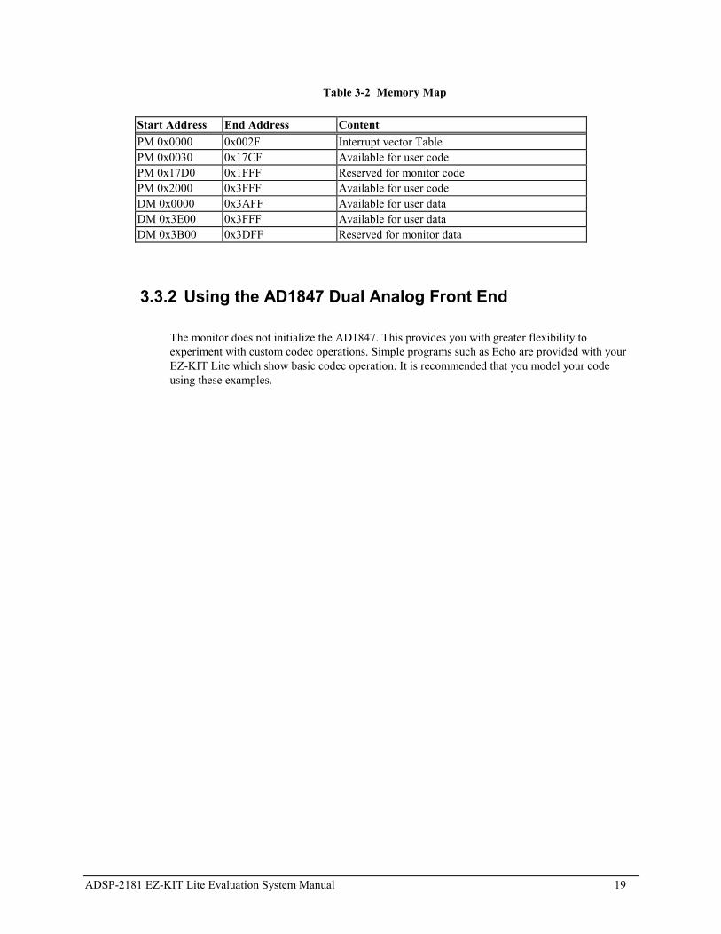
3.3.1 ADSP-2181 Memory Map
The ADSP-2181 EZ-KIT Lite board contains 80K bytes configured as 16K x 24 program memoryand 16K x 16 of internal SRAM that can be used for either program or data storage. Theconfiguration of on-chip SRAM is detailed in the ADSP-2181 data sheet. Table 3-2 shows thememory map of the ADSP-2181 EZ-KIT Lite.
ADSP-2181 EZ-KIT Lite Evaluation System Manual 19
Table 3-2 Memory Map
Start Address End Address ContentPM 0x0000 0x002F Interrupt vector TablePM 0x0030 0x17CF Available for user codePM 0x17D0 0x1FFF Reserved for monitor codePM 0x2000 0x3FFF Available for user codeDM 0x0000 0x3AFF Available for user dataDM 0x3E00 0x3FFF Available for user dataDM 0x3B00 0x3DFF Reserved for monitor data
3.3.2 Using the AD1847 Dual Analog Front End
The monitor does not initialize the AD1847. This provides you with greater flexibility toexperiment with custom codec operations. Simple programs such as Echo are provided with yourEZ-KIT Lite which show basic codec operation. It is recommended that you model your codeusing these examples.
ADSP-2181 EZ-KIT Lite Evaluation System Manual 20
4.1 Overview
This chapter describes loading and running the demonstration programs supplied with the ADSP-2181EZ-KIT Lite board. The demos are designed to run on the VisualDSP debugger which is supplied on theCD-ROM that shipped with this product. For detailed information on debugger features and operation,see the VisualDSP User�s Guide for ADSP-21xx Family DSPs.
4.2 Starting the VisualDSP Debugger
After the VisualDSP software and license have been installed, click the Windows Start menu.
1. Select Programs/VisualDSP/Debugger from under the Start menu.
The debugger interface appears
2. From the Session menu, select New Session.
The Target Selection dialog appears
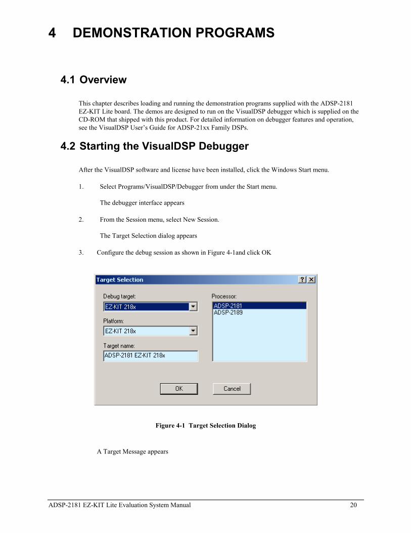
3. Configure the debug session as shown in Figure 4-1and click OK
Figure 4-1 Target Selection Dialog
A Target Message appears
4 DEMONSTRATION PROGRAMS
ADSP-2181 EZ-KIT Lite Evaluation System Manual 21
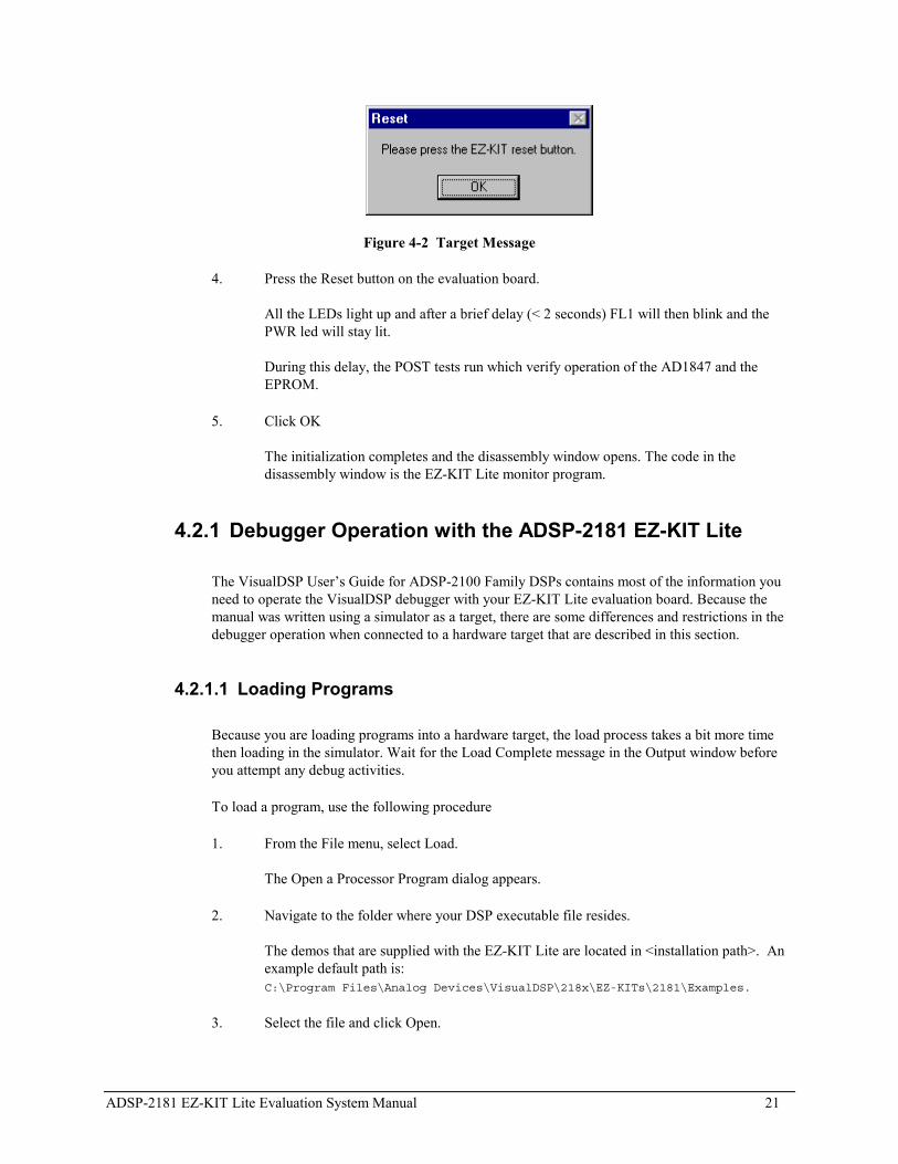
Figure 4-2 Target Message
4. Press the Reset button on the evaluation board.
All the LEDs light up and after a brief delay (< 2 seconds) FL1 will then blink and thePWR led will stay lit.
During this delay, the POST tests run which verify operation of the AD1847 and theEPROM.
5. Click OK
The initialization completes and the disassembly window opens. The code in thedisassembly window is the EZ-KIT Lite monitor program.
4.2.1 Debugger Operation with the ADSP-2181 EZ-KIT Lite
The VisualDSP User�s Guide for ADSP-2100 Family DSPs contains most of the information youneed to operate the VisualDSP debugger with your EZ-KIT Lite evaluation board. Because themanual was written using a simulator as a target, there are some differences and restrictions in thedebugger operation when connected to a hardware target that are described in this section.
4.2.1.1 Loading Programs
Because you are loading programs into a hardware target, the load process takes a bit more timethen loading in the simulator. Wait for the Load Complete message in the Output window beforeyou attempt any debug activities.
To load a program, use the following procedure
1. From the File menu, select Load.
The Open a Processor Program dialog appears.
2. Navigate to the folder where your DSP executable file resides.
The demos that are supplied with the EZ-KIT Lite are located in <installation path>. Anexample default path is:C:\Program Files\Analog Devices\VisualDSP\218x\EZ-KITs\2181\Examples.
3. Select the file and click Open.

ADSP-2181 EZ-KIT Lite Evaluation System Manual 22
The file loads and the message Load Complete appears in the Output window when theload process has completed.
4.2.1.2 Registers and Memory
To see current values in registers and memory, use the F12 key or the Window, Refresh command.
! Register and memory contents may not be changed while the user program is running.
4.2.1.3 Setting Breakpoints and Stepping
! Breakpoints set in the last three instructions of a do-loop are allowed, but this causesimproper debugger operation.
" The debugger automatically inserts breakpoints at the function Main(), when the Settings, Run To Main command is checked, and at the _exit instruction.
4.2.1.4 Resetting the EZ-KIT Lite Board
The EZ-KIT Lite board can be reset with the push button switch on the board or with the Debug,Reset command in the debugger. After performing a reset, you will need to reload any programsyou were running. The Debug, Restart command also resets the processor. However, the processorretains all debug information and memory contents.
" The following sequence must be used when starting the debugger:
1. Start the debugger from the windows Start menu.
The debugger starts and the Target message Hit Reset Button appears
2. Press the Reset button
3. Click OK.
! Do not use the reset button while the debugger is open unless the debugger requests you to press it.
4.3 Demonstration Programs
The demos included with the EZ-KIT Lite are designed to show you the features and capabilities of theADSP-2181 DSP. The demos are listed by the executable file name and are described by their output. Allof the demos are located in <installation path>. An example default path is: C:\Program Files\Analog
Devices\VisualDSP\218x\EZ-KITs\2181\Examples.

ADSP-2181 EZ-KIT Lite Evaluation System Manual 23
! Do not run more than one ADSP-2181 EZ-KIT Lite session in the debugger at any one time. You may run an EZ-KIT Lite session and a simulator or ICE session at the same time or you can open two debugger interfaces to run more than one EZ-KIT Lite session.
4.3.1 ADPCM.dxe
This program demonstrates Adaptive Differential Pulse Code Modulation (ADPCM) capabilities.ADPCM consists of a number of real-time speech compression algorithms.
4.3.2 DTMF.dxe
This demonstration generates Dual-Tone Multi-Frequency (DTMF) tones, as used in the telephonenetwork for pushbutton signaling. A DTMF tone is composed of two different single frequencytone, one of four row tones added to one of four column tones. Thus, a full implementation of aDTMF standard tone generator can generate 16 different tones (only 12 are commonly used onconsumer handsets).
4.3.3 ECHO.dxe
This demonstration uses the codec to generate an echo and the four channel DAC to display the tapsof the echo canceller.
4.3.4 Primes70.dxe
This demonstration is a C program that generates the first 20 prime numbers.
4.3.5 FIRDEMO.dxe
This demonstration starts with a talk-through program. The AD1847 codec digitizes the analogmicrophone input and transmits the data to the DSP�s serial port. The DSP reads data from theserial port and retransmits the data back to the codec. The codec converts the data to an analogsignal that drives the speaker. No digital signal processing is performed on the data. When youspeak into the microphone, you should hear your voice through the speaker.
The filters have equivalent bandwidth and are evenly spaced on a logarithmic frequency axis. AllFIR filters are 256 taps, and have been desired for 0.1 ripple.
FIR Filter Lower Stop Band Pass Band Upper Stop BandFIR1 0 - 269 Hz 328 - 448 Hz 547 - 4000 HzFIR2 0 - 426 Hz 521 - 710 Hz 866 - 4000 HzFIR3 0 - 675 Hz 825 - 1125 Hz 1375 - 4000 HzFIR4 0 - 1070 Hz 1308 - 1783 Hz 2179 - 4000 Hz
ADSP-2181 EZ-KIT Lite Evaluation System Manual 24
4.3.6 LPC2K4.dxe
Push the Interrupt button on EZ-KIT Lite to toggle between talk through and 2.4k LPC encoding.The red LED will light up when LPC encoding is in effect.
4.3.7 LPC7K8.dxe
Push the Interrupt button on EZ-KIT Lite to toggle between talk through and 7.8k LPC encoding.The red LED will light up when LPC encoding is in effect.
4.4 Reference
This section is a reference for the VisualDSP debugger. Because the debugger is dynamic, menuselections, commands, and dialogs change depending on the target you are debugging. This chapterprovides information on all of the menu selections, commands, and dialogs when the target is theADSP-2181 evaluation board. For all other debugger commands, see the VisualDSP User�s Manual forADSP-2100 Family DSPs. Note that grayed out commands are unavailable with this target.
4.4.1 Settings Menu Commands
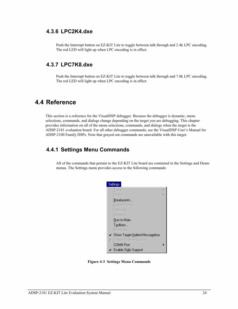
All of the commands that pertain to the EZ-KIT Lite board are contained in the Settings and Demomenus. The Settings menu provides access to the following commands:
Figure 4-3 Settings Menu Commands
ADSP-2181 EZ-KIT Lite Evaluation System Manual 25
4.4.1.1 Baud Rate
Sets up the baud rate of the COM port. Choices are 9600, 14400, 19200, 57600, and 115200 withthe emulator with a default rate of 57600. The only choice while using the monitor program is9600. Once you change this you do not need to reset it for subsequent debug sessions.
" The debugger will have trouble halting at a baud rate over 9600 while using the monitor program.
4.4.1.2 Comm Port
Selects a PC communications port for the EZ-KIT Lite board. Choices are Comm 1-4.

ADSP-2181 EZ-KIT Lite Evaluation System Manual 26
5.1 OverviewThis chapter discusses hardware design issues on the ADSP-2181 EZ-KIT Lite board. The EZ-KIT Liteboard schematics are available as an insert at the end of this manual.
5.2 EZ-KIT Lite Specifications Processor: ADSP-2181KS-133 operating at an instruction rate of
33 MHz (16.667 external clock)
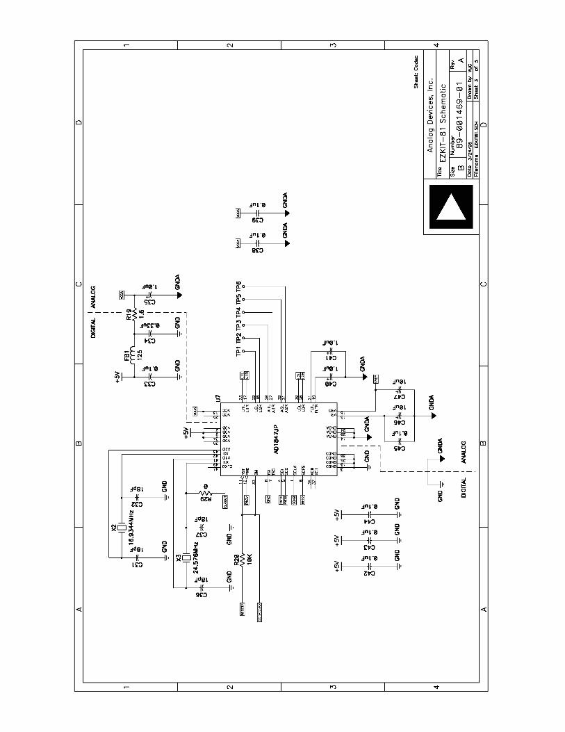
Analog interface: AD1847 stereo codec
Analog inputs: One stereo pair of 2V RMS AC coupled line level inputsOne stereo pair of 20mV RMS AC coupled microphone inputs
Analog outputs: One stereo pair of 1V RMS AC coupled line level outputs
Power source: 8 to 10V DC at 300mA
Environment: 0 to 70× centigrade; 10 to 90 percent relative humidity (non condensing)
5 WORKING WITH EZ-KIT LITE HARDWARE

ADSP-2181 EZ-KIT Lite Evaluation System Manual 27
5.3 System Architecture
Figure 5-1 EZ-KIT Lite System Block Diagram

ADSP-2181 EZ-KIT Lite Evaluation System Manual 28
5.4 Board LayoutFigure 5-2 shows the layout of the EZ-KIT Lite board. This figure highlights the locations of the majorcomponents and connectors. Each of these major components is described in the following sections.
Figure 5-2 EZ-KIT Lite Board Layout
5.4.1 Socketed Memory
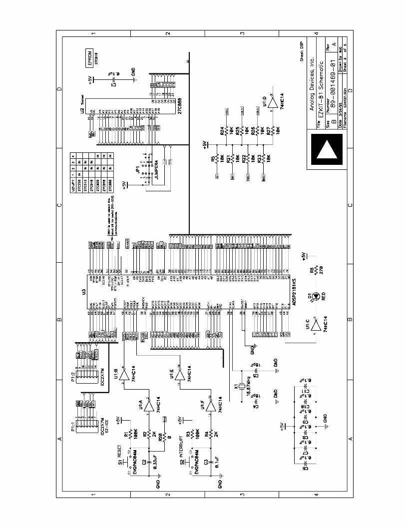
The socketed EPROM provides up to 128k x 8 bits of program storage that can be loaded by theADSP-2181 when it is programmed to boot from the socketed EPROM. After the ADSP-2181 isreset, the BDMA feature is used to load the first 32 words of program memory from the bytememory space. Program execution is held off until all 32 words are loaded. Refer to the ADSP-2100 Family User�s Manual and the ADSP-2181 data sheet for more information on programbooting and processor modes.
5.4.2 User LEDs
D1 is a red light emitting diode which is controlled by the FL1 output of the ADSP-2181processor. Software can control the state of this indicator by writing to an internal register.

ADSP-2181 EZ-KIT Lite Evaluation System Manual 29
D2 is a green light emitting diode which is on whenever the board has power.
5.4.3 Switches
S1 is the reset push button switch. Pushing this button causes the ADSP-2181 processor and theAD1847 codec to enter the hardware reset state and remain there until it is released.The switch outputs are de-bounced electronically to prevent multiple transitions due to mechanicalcontact bounce.
S2 is the interrupt push button switch. Pushing this button causes the ADSP-2181 to receive anIRQE interrupt input. The processor then executes the current IRQE interrupt handler software ifthe interrupt is enabled and the IRQE interrupt vector is in place. The interrupt switch output is de-bounced electronically to prevent multiple interrupts due to mechanical contact bounce.
5.4.4 Power Connector
The power connector supplies DC voltages to the EZ-KIT Lite board. Table5-1 shows the powerconnector pinout. If you do not use the power supply provided with your EZ-KIT Lite board,replace it with one that has the connections shown in Table 5-1.
Table 5-1 Power Connection
Terminal ConnectionCenter pin 8 � 10v DC @ 300mAOuter Ring positive
5.4.5 European Power Supply Specifications
Table 5-2 European Power Supply Specifications
DC VOLTAGE: 8 to 10V DCCURRENT: 300mADC CONNECTOR:Type: Switchcraft 760 style, FEMALEPlug Size: 5.5 (OD) X 2.1 (ID) X 12
(length) millimetersPolarity: Center is Negative (inside
terminal)

ADSP-2181 EZ-KIT Lite Evaluation System Manual 30
5.4.6 AD1847 Connections
When the AD1847 is enabled on the EZ-KIT Lite board, you can access the audio input and outputjacks on the board. Each of the audio connectors are stereo mini jacks and accept standardcommercially available stereo mini plugs.
The Microphone/Line_in Input jack connects to the LINE_IN_L (left) and LINE_IN_R (right)pins or the MIC1 and MIC2 of the AD1847 SoundPort Stereo codec, depending on the setting ofjumpers JP2. For more information see the connections descriptions.
The LINE Output jack connects to the left (L) LINE_OUT and right (R) LINE_OUT pins of thecodec.
5.4.7 Expansion Port Connectors
The two expansion port connectors provide access to the bus signals of the ADSP-2181. Onepossibility for the use of these connectors, beyond debugging, is host control. All interrupts, bussignals, and PWM event signals are available through this port. For more information, see�Expansion Connectors�.
! WARNING: External port loading can effect external bus speed and performance.
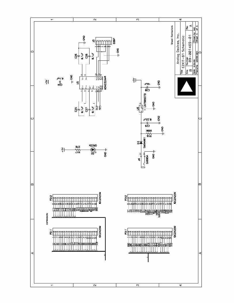
5.4.8 Connectors and Headers
J1 is a 1/8 inch (3.5 mm) stereo jack. This jack is used to bring either line level or microphoneaudio signals into the board.
J2 is also a 1/8 inch (3.5 mm) stereo jack. This jack is used to bring out line level audio signalsfrom the board.
J3 is a female 9-pin D-Sub connector. It is used to communicate with a host computer usingRS-232 signal levels and asynchronous serial protocols.
J4 is a jack for a 5.5 mm cylindrical plug. It is used to supply power to the board. The center pinof the jack is 2 mm diameter and should connect to the negative side of the power source. Theouter sleeve of the mating plug must be positive.
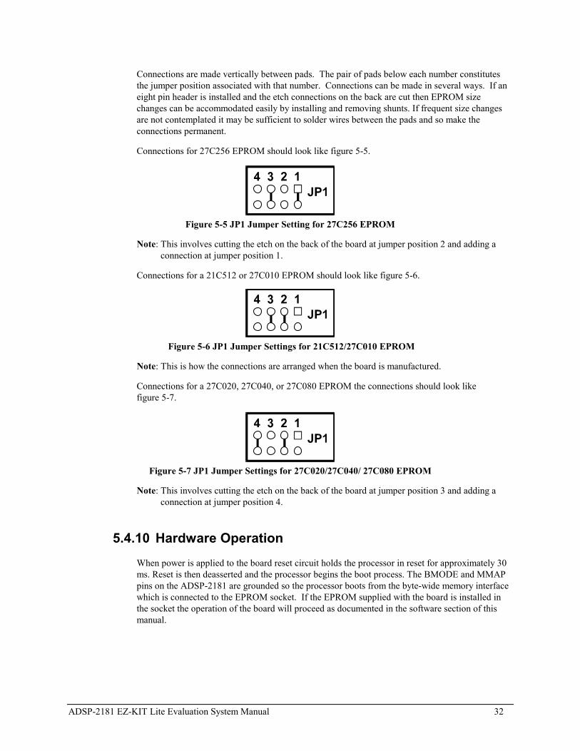
JP1 is a site for an eight pin header. It can be used to configure the board for EPROM sizes otherthan the 1 Mbit (128K byte) EPROM (27C010) shipped with the board. Most users will not needthis feature. For more information see section on EPROM Jumper Settings.
JP2, shown in figure 5-3, is a six pin header. It is used to configure input jack J1 for either linelevel or microphone input. The center pin in each group of three is connected to one of theAD1847 codec�s input pins. Jumpers (also known as shunts or shorting links) can be used toconnect these pins to either the output of the microphone amplifier or to the output of the line levelinput filter.
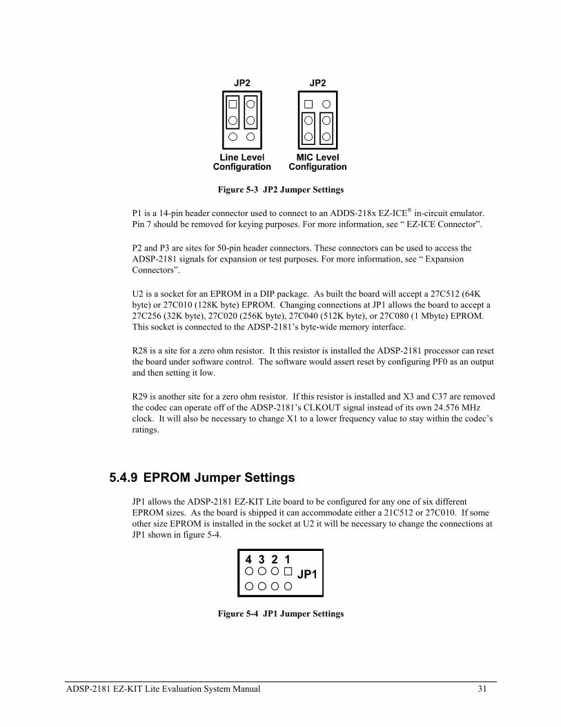
ADSP-2181 EZ-KIT Lite Evaluation System Manual 31
Figure 5-3 JP2 Jumper Settings
P1 is a 14-pin header connector used to connect to an ADDS-218x EZ-ICE® in-circuit emulator.Pin 7 should be removed for keying purposes. For more information, see � EZ-ICE Connector�.
P2 and P3 are sites for 50-pin header connectors. These connectors can be used to access theADSP-2181 signals for expansion or test purposes. For more information, see � ExpansionConnectors�.
U2 is a socket for an EPROM in a DIP package. As built the board will accept a 27C512 (64Kbyte) or 27C010 (128K byte) EPROM. Changing connections at JP1 allows the board to accept a27C256 (32K byte), 27C020 (256K byte), 27C040 (512K byte), or 27C080 (1 Mbyte) EPROM.This socket is connected to the ADSP-2181�s byte-wide memory interface.
R28 is a site for a zero ohm resistor. It this resistor is installed the ADSP-2181 processor can resetthe board under software control. The software would assert reset by configuring PF0 as an outputand then setting it low.
R29 is another site for a zero ohm resistor. If this resistor is installed and X3 and C37 are removedthe codec can operate off of the ADSP-2181�s CLKOUT signal instead of its own 24.576 MHzclock. It will also be necessary to change X1 to a lower frequency value to stay within the codec�sratings.
5.4.9 EPROM Jumper SettingsJP1 allows the ADSP-2181 EZ-KIT Lite board to be configured for any one of six differentEPROM sizes. As the board is shipped it can accommodate either a 21C512 or 27C010. If someother size EPROM is installed in the socket at U2 it will be necessary to change the connections atJP1 shown in figure 5-4.
Figure 5-4 JP1 Jumper Settings
ADSP-2181 EZ-KIT Lite Evaluation System Manual 32
Connections are made vertically between pads. The pair of pads below each number constitutesthe jumper position associated with that number. Connections can be made in several ways. If aneight pin header is installed and the etch connections on the back are cut then EPROM sizechanges can be accommodated easily by installing and removing shunts. If frequent size changesare not contemplated it may be sufficient to solder wires between the pads and so make theconnections permanent.
Connections for 27C256 EPROM should look like figure 5-5.
Figure 5-5 JP1 Jumper Setting for 27C256 EPROM
Note: This involves cutting the etch on the back of the board at jumper position 2 and adding a connection at jumper position 1.
Connections for a 21C512 or 27C010 EPROM should look like figure 5-6.
Figure 5-6 JP1 Jumper Settings for 21C512/27C010 EPROM
Note: This is how the connections are arranged when the board is manufactured.
Connections for a 27C020, 27C040, or 27C080 EPROM the connections should look likefigure 5-7.
Figure 5-7 JP1 Jumper Settings for 27C020/27C040/ 27C080 EPROM
Note: This involves cutting the etch on the back of the board at jumper position 3 and adding a connection at jumper position 4.
5.4.10 Hardware OperationWhen power is applied to the board reset circuit holds the processor in reset for approximately 30ms. Reset is then deasserted and the processor begins the boot process. The BMODE and MMAPpins on the ADSP-2181 are grounded so the processor boots from the byte-wide memory interfacewhich is connected to the EPROM socket. If the EPROM supplied with the board is installed inthe socket the operation of the board will proceed as documented in the software section of thismanual.

ADSP-2181 EZ-KIT Lite Evaluation System Manual 33
5.4.11 EZ-ICE Connector
The ADSP-218x EZ-ICE® Emulator aids in the hardware debugging of an ADSP-2181 system.The emulator consists of hardware, host computer resident software, and the target boardconnector. The ADSP-2181 integrates on-chip emulation support with a 14-pin ICE-Port interface(Figure 5-3). This interface provides a simpler target board connection that requires fewermechanical clearance considerations than other ADSP-2100 Family EZ-ICEs. The ADSP-2181device need not be removed from the target system when using the EZ-ICE, nor are any adaptersneeded. Due to the small footprint of the EZ-ICE connector, emulation can be supported in finalboard designs.
The EZ-ICE performs a full range of functions, including:
• In-target operation
• Up to 30 breakpoints
• Single-step or full-speed operation
• Registers and memory values can be examined and altered
• PC upload and download functions
• Instruction-level emulation of program booting and execution
• Complete assembly and disassembly of instructions
• C source-level debugging
Figure 5-8 EZ-ICE 14-Pin Header (P6)For more information on connecting to an ICE, see the ADSP-2181 data sheet andapplication note EE-34.
5.5 Designing an EZ-ICE Compatible TargetThis section describes the ADSP-218x family EZ-ICE theory of operation to aid you in your design of acompatible target system.
ADSP-2181 EZ-KIT Lite Evaluation System Manual 34
The hardware consists of a printed circuit board measuring 3.5 inches by 5.5 inches. Assembled onto theprinted circuit board are an ADSP-2181 digital signal processor, a socketed EPROM, an AD1847 codecand various support circuits and connectors. The board is a complete signal processing system designedto demonstrate the capabilities of the ADSP-2181 digital signal processor. It can also be used as aplatform to develop new applications for the ADSP-2181.
The EZ-KIT Lite board is an example of a minimum implementation of an ADSP-2181 processor. Thesocketed EPROM is connected to the processor via the Byte DMA Port. This interface uses only eight ofthe twenty-four data lines to carry data (D8 through D15). Eight of the spare data lines (D16 throughD23) are used to provide additional address bits. This allows the ADSP-2181 to address up to 32 Mbits(4 Mbytes) of memory. The DSP is configured to boot from the socketed EPROM when RESET is de-asserted or if power is applied to the board.
The AD1847 codec is connected to the DSP via SPORT0. This high speed synchronous serial port carriesall of the data, control, and status information between the DSP and the codec. It is possible to disable thecodec if the serial port is to be used for another purpose. The CODECDIS signal available on connectorP3 can be used to disable the codec. When this signal is brought low, the codec is disabled and its signalsare put in a high impedance state.
The SPORT1 pins are used to communicate with the host PC via the RS-232 interface (J3). The Flag Inand Flag Out pins carry the receive and transmit data. Software running on the DSP emulates a UART toprovide the proper protocol for asynchronous serial communications up to a data rate of 115K bits persecond.
5.5.1 Hardware Debugging
If the green LED fails to light, check your power connections. Verify that your power supply hasthe proper size connector and that the polarity is correct. The power supply voltage measured atthe connector to the board should be 8V to 10V DC. Also, make sure that there are no objectsbeneath or on top of the board that may be causing a short circuit. Hit the reset button (S1) if theboard appears to be operating improperly.
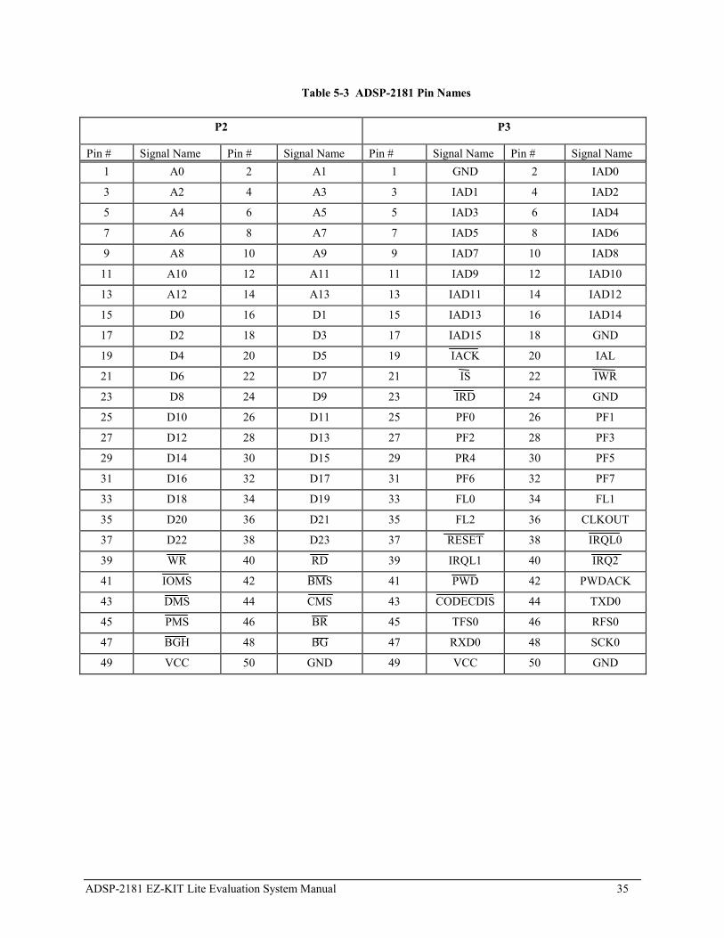
5.6 Expansion ConnectorsThe two expansion connectors provide access to the ADSP-2181�s interface pins. These pins let youwatch data transmissions. In addition, the host interface, interrupt, and pwm_event pins are also availableon this connector.
P2 and P3 are sites for 50-pin header connectors. These connectors can be used to access the ADSP-2181signals for expansion or test purposes. The pin numbers on these connectors are arranged as follows.
Figure 5-9 Expansion Connector
The signals available on these pins are shown in Table 5-3.
ADSP-2181 EZ-KIT Lite Evaluation System Manual 35
Table 5-3 ADSP-2181 Pin Names
P2 P3
Pin # Signal Name Pin # Signal Name Pin # Signal Name Pin # Signal Name1 A0 2 A1 1 GND 2 IAD0
3 A2 4 A3 3 IAD1 4 IAD2
5 A4 6 A5 5 IAD3 6 IAD4
7 A6 8 A7 7 IAD5 8 IAD6
9 A8 10 A9 9 IAD7 10 IAD8
11 A10 12 A11 11 IAD9 12 IAD10
13 A12 14 A13 13 IAD11 14 IAD12
15 D0 16 D1 15 IAD13 16 IAD14
17 D2 18 D3 17 IAD15 18 GND
19 D4 20 D5 19 IACK 20 IAL
21 D6 22 D7 21 IS 22 IWR
23 D8 24 D9 23 IRD 24 GND
25 D10 26 D11 25 PF0 26 PF1
27 D12 28 D13 27 PF2 28 PF3
29 D14 30 D15 29 PR4 30 PF5
31 D16 32 D17 31 PF6 32 PF7
33 D18 34 D19 33 FL0 34 FL1
35 D20 36 D21 35 FL2 36 CLKOUT
37 D22 38 D23 37 RESET 38 IRQL0
39 WR 40 RD 39 IRQL1 40 IRQ2
41 IOMS 42 BMS 41 PWD 42 PWDACK
43 DMS 44 CMS 43 CODECDIS 44 TXD0
45 PMS 46 BR 45 TFS0 46 RFS0
47 BGH 48 BG 47 RXD0 48 SCK0
49 VCC 50 GND 49 VCC 50 GND
ADSP-2181 EZ-KIT Lite Evaluation System Manual 36
APPENDIX A RESTRICTIONS
APPENDIX B Restrictions
The following restrictions apply to release 1.1 of the ADSP-2181 EZ-KIT Lite evaluation board. Forinformation on any ADSP-2181 silicon anomalies, see the anomaly sheet that accompanied this product.
1. Breakpoints set in the last three instructions of a do-loop are allowed, but cause your code to runincorrectly.
2. The host loses contact with the monitor while the user program is running if the user program disablesthe Timer interrupt or changes the Timer interrupt vector.
3. The host loses contact with the monitor while the program is running and in an ISR when nesting isturned on.
4. Do not use the reset button while the debugger is open unless the debugger requests you to. Thiscauses the debugger to stop communicating.
5. Do not run more than one ADSP-2181 EZ-KIT Lite session in the debugger at any one time. You mayrun an EZ-KIT Lite session and a simulator or ICE session at the same time or you can open twodebugger interfaces to run more than one EZ-KIT Lite session.

ADSP-2181 EZ-KIT Lite Evaluation System Manual 37
APPENDIX C BILL OF MATERIALS The following is a list of the components that are supplied on the EZ-KIT Lite evaluation board. ITEM QTY DESC PART NO BOARD REF NO 1 1 Jack, Power DJ005A J4 2 1 Jack, Stereo GND J-353-1000 J1 3 1 Jack, Stereo J-353-103 J2 4 2 Push Button, N.O.(Thru-hole) EVQPAC04M S1, S2 5 20 Capacitor 1206 0.1uF MCH315C104M C1 C3 C6-C11 C24-C28
C33 C38 C39 C42-C45 6 7 Capacitor 1206 0.33uF MCH312C334M C2 C12 C17 C19 C22 C29
C34 7 6 Capacitor 1206 18pF MCH315A180J C4 C5 C31 C32 C36 C37 8 2 Capacitor 1206 220pF MCH315SL221K C14 C21 9 2 Capacitor 1206 560pF MCH315SL561K C13 C23 10 7 Capacitor, Aluminum 1.0uF SMT CB1/50BM C15 C16 C18 C20 C35
C40 C41 11 3 Capacitor, Aluminum 10uF SMT CB10/16BM C30 C46 C47 12 1 Connector, DB9 Female DDFEX J3 13 1 Crystal 16.67MHz ABL-16.667MHZ X1 14 1 Crystal 16.9344MHz ABL-16.9344MHZ X2 15 1 Crystal 24.576MHz ABL-24.576MHZ X3 16 1 DIODE SMB4001 D3 17 1 1 Mbit EPROM MX27C010DC-20 U2 18 1 Ferrite Bead 125 Ohm @ 100MHz BCB-1812 FB1 19 1 Header, SQ. Pin 2x7 TSW-107-07-T-D P1 20 1 Header, SQ. Pin 2x3 TSW-103-07-T-Q JP2 21 1 LED, Green 5mm LN31GPHL D2 22 1 LED, Red 5mm LN21RPHL D1 23 1 IC, CODEC AD1847JP U7 24 1 IC, DSP ADSP2181KS U3 25 1 IC, Hex inverter MC74HC14AD U1 26 1 IC, Dual OPAMP SSM2135S U4 27 1 IC, Regulator 5 Volt TO-220 LM78M05CT U6 28 1 IC, RS-232 Interface ADM232AARN U5 29 1 PCB, ESDSP-81 65-000286-01 30 3 Resistor, 1/8W 5% 1206 100K MCR18-EZHU-J-104 R1 R3 R18 31 9 Resistor, 1/8W 5% 1206 10K MCR18-EZHU-J-103 R20-R27 R5 32 2 Resistor, 1/8W 5% 1206 240K MCR18-EZHU-J-244 R14 R9 33 2 Resistor, 1/8W 5% 1206 270 MCR18-EZHU-J-271 R17 R6 34 2 Resistor, 1/8W 5% 1206 2K MCR18-EZHU-J-202 R2 R4 35 2 Resistor, 1/8W 5% 1206 47K MCR18-EZHU-J-473 R11 R13 36 6 Resistor, 1/8W 5% 1206 5.1K MCR18-EZHU-J-512 R10 R12 R15 R16 R7 R8 37 1 Resistor, 1/8W 5% 1206 1.6 MCR18-EZHU-K-1R6 R19 38 4 Rubber bumper, gray SJ-5018924157-R 39 2 Shunt On header at JP2 40 1 Socket, 32 Pin Dip 2-644018-5 U2

ADSP-2181 EZ-KIT Lite Evaluation System Manual 38
APPENDIX A SCHEMATICS


ADSP-2181 EZ-KIT Lite Evaluation System Manual 39
A
ADPCM.dxe............................................................ 23ADSP-2181
interrupts ............................................................. 14
B
Baud Rate command ............................................... 25Baud rate settings .................................................... 16Board features ........................................................... 7Board layout............................................................ 28Board switches ........................................................ 29Boot PROM ............................................................ 28Break Points/Single Step......................................... 17
C
Codec Check/Initialization...................................... 16Codec Transmissions .............................................. 17Comm Port command.............................................. 25Commands
Baud Rate............................................................ 25Comm Port .......................................................... 25
ConnectorsAD1847............................................................... 30EZ-ICE................................................................ 33power................................................................... 29
Connectors and headers........................................... 30Contents of package ................................................ 10Customer support ...................................................... 8
D
Debuggerstarting................................................................. 20
Demo programsoverview.............................................................. 20
Demonstration programsADPCM .............................................................. 23DTMF ................................................................. 23ECHO.................................................................. 23FIRDEMO........................................................... 23LPC2K4 .............................................................. 24LPC7K8 .............................................................. 24Primes70 ............................................................. 23
DTMF.dxe............................................................... 23
E
ECHO.dxe............................................................... 23Electrostatic Discharge............................................ 10EPROM tests........................................................... 16ESD......................................................................... 10Expansion connectors.............................................. 34EZ-ICE Connector .................................................. 33EZ-KIT Lite board layout ....................................... 28
EZ-KIT Lite Specifications..................................... 26
F
FIRDEMO.dxe........................................................ 23FLAG I/O pins ........................................................ 14
H
Hardware installation .............................................. 11
I
IMASK register....................................................... 14Installing EZ-KIT Lite hardware............................. 11Installing EZ-KIT Lite software.............................. 13Installing the license................................................ 12Installing VisualDSP............................................... 11Interrupts
restrictions........................................................... 14
L
Layoutevaluation board.................................................. 28
LEDs ....................................................................... 28License installation.................................................. 12LPC2K4.dxe............................................................ 24LPC7K8.dxe............................................................ 24
M
Memory checks ....................................................... 15Memory map ........................................................... 18Monitor program components
command processing ........................................... 17halt loop .............................................................. 17UART ISR segment ............................................ 17
P
Package contents ..................................................... 10POST routines......................................................... 15Power connector...................................................... 29Power On Self Test ................................................. 15Power-on reset......................................................... 15Primes70.dxe........................................................... 23Program memory
booting ................................................................ 28
R
Registering VisualDSP............................................ 13Registers
ICNTL................................................................. 14IMASK................................................................ 14
Resetting the board.................................................. 15Restrictions ............................................................. 36
ADSP-2181 EZ-KIT Lite Evaluation System Manual 40
S
Selecting a target ..................................................... 20Software installation.......................................... 12, 13Specifications of the EZ-KIT Lite........................... 26SPORTs .................................................................. 15Standard Operation ................................................. 16Starting the debugger .............................................. 20Static discharge ....................................................... 10Switches .................................................................. 29System Architecture ................................................ 27System requirements ............................................... 11
T
Target selection....................................................... 20Technical support...................................................... 8Transfers
Codec .................................................................. 17Troubleshooting ...................................................... 34
U
UART Check/Initialization ..................................... 16User LEDs............................................................... 28
V
VisualDSP................................................................. ii