ADMS-BIS Bouwkundige Informatiesystemen ADMS 2006 UML part 1 Jan Dijkstra - 9 oktober 2006 ADMS-BIS.
58
ADMS-BIS Bouwkundige Informatiesystemen ADMS 2006 UML part 1 Jan Dijkstra - 9 oktober 2006 ADMS-BIS
-
date post
21-Dec-2015 -
Category
Documents
-
view
237 -
download
5
Transcript of ADMS-BIS Bouwkundige Informatiesystemen ADMS 2006 UML part 1 Jan Dijkstra - 9 oktober 2006 ADMS-BIS.
AD
MS
-BIS
Bouwkundige InformatiesystemenADMS 2006
UML part 1
Bouwkundige InformatiesystemenADMS 2006
UML part 1
Jan Dijkstra - 9 oktober 2006
AD
MS
-BIS
AD
MS
-BIS
SubjectsSubjects
• Software EngineeringSoftware Engineering• Software RequirementsSoftware Requirements
– IntroductionIntroduction– A use case approachA use case approach
• UML : Use Case UML : Use Case ModellingModelling• Exercise UCDExercise UCD• Discussion exercise UCD• UML Introduction• UML : Activity Diagram• Microsoft Visio• Task UML-part 1
AD
MS
-BIS
UML IntroductionUML Introduction

AD
MS
-BIS
Information system design with UMLInformation system design with UML
• Having knowledge of the visual modelling language UML in the field of ICT.
• Gain a clear understanding of applying this knowledge for specifying, constructing, visualizing and documenting software-intensive systems.
AD
MS
-BIS
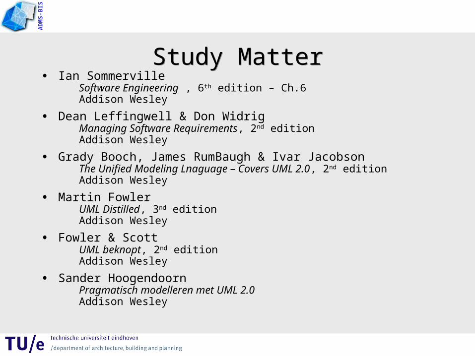
Study MatterStudy Matter• Ian Sommerville
Software Engineering , 6th edition – Ch.6Addison Wesley
• Dean Leffingwell & Don WidrigManaging Software Requirements, 2nd editionAddison Wesley
• Grady Booch, James RumBaugh & Ivar JacobsonThe Unified Modeling Lnaguage – Covers UML 2.0, 2nd editionAddison Wesley
• Martin FowlerUML Distilled, 3nd editionAddison Wesley
• Fowler & ScottUML beknopt, 2nd editionAddison Wesley
• Sander HoogendoornPragmatisch modelleren met UML 2.0Addison Wesley
AD
MS
-BIS
About UMLAbout UML
• UML offers a standard way to write a system’s blueprints, including conceptual things such as business processes and system functions as well as database schemas.
• UML is a modelling language, a notation used to express and document designs.
AD
MS
-BIS
What is the UML?What is the UML?
The Unified Modelling Language (UML) is the successor to the wave of object-oriented analysis and design (OOA&D) methods that appeared in the late ’80s and early ’90s.
It unifies the methods of Booch, Rumbaugh (OMT), and Jacobson (3 amigo’s).
AD
MS
-BIS
Data and Processes Data and Processes
• Traditional, the division between data and processes– were structured separately,– and functions made use of data
• For OO– an object contains data and processes
• encapsulation• information hiding
– avoiding domino effect adaptations– more simple and cheaper maintenance
AD
MS
-BIS
Domain modellingDomain modelling
• Traditional, functional decomposition was the strategy– adaptations are difficult
• For OO– domain modelling independent of the required functions
• objects encapsulates functionality • It is easier to make adaptations and extensions
AD
MS
-BIS
UML is for modellingUML is for modelling
• Building models of complex systems because one cannot comprehend such a system in its entirely.
• At this, a model – is a simplification of reality– is a set of blueprints of a system– is an abstraction of something for the purpose of
understanding it before building it– may be expressed a different level of expression (no
single model is sufficient)

AD
MS
-BIS
UML is for visualizingUML is for visualizing
• An explicit model facilitates communication.
• UML symbols are based on well-defined semantics.

AD
MS
-BIS
UML is for specifying and constructing
UML is for specifying and constructing
• Specifying means building models that are precise, unambiguous and complete.
• UML addresses the specification of all the important analysis, design, and implementation decisions made in developing and deploying a software system.
AD
MS
-BIS
UML is for documentingUML is for documenting
• UML addresses the documentation of a systems architecture and all of its details.

AD
MS
-BIS
UML is a languageUML is a language
• UML is a visual language for software blueprints– with a vocabulary and rules for communication;– and a focus on conceptual and physical
representations.

AD
MS
-BIS
UML: graphical notations 1UML: graphical notations 1

AD
MS
-BIS
UML: graphical notations 2UML: graphical notations 2

AD
MS
-BIS
UML Models, Views and DiagramsUML Models, Views and Diagrams
• A diagram is a view into a model– presented from the aspect of a particular
stakeholder– and provides a partial representation of the
system

AD
MS
-BIS
UML ViewsUML Views
Design view
Interaction view
Implementa-tion view
Deployment view
Use Case view
vocabularyfunctionality
behaviour
performancescalabilitythroughput
system assemblyconfiguration management
system topologydistributiondeliveryinstallation
physicallogical

AD
MS
-BIS
UML DiagramsUML Diagrams
• Structure diagram– Class diagram– Object diagram– Component diagram– Composite structure
diagram– Deployment diagram– Artifact diagram
• Behaviour diagram– Use Case diagram– Sequence diagram– Communication
diagram– State diagram– Activity diagram
AD
MS
-BIS
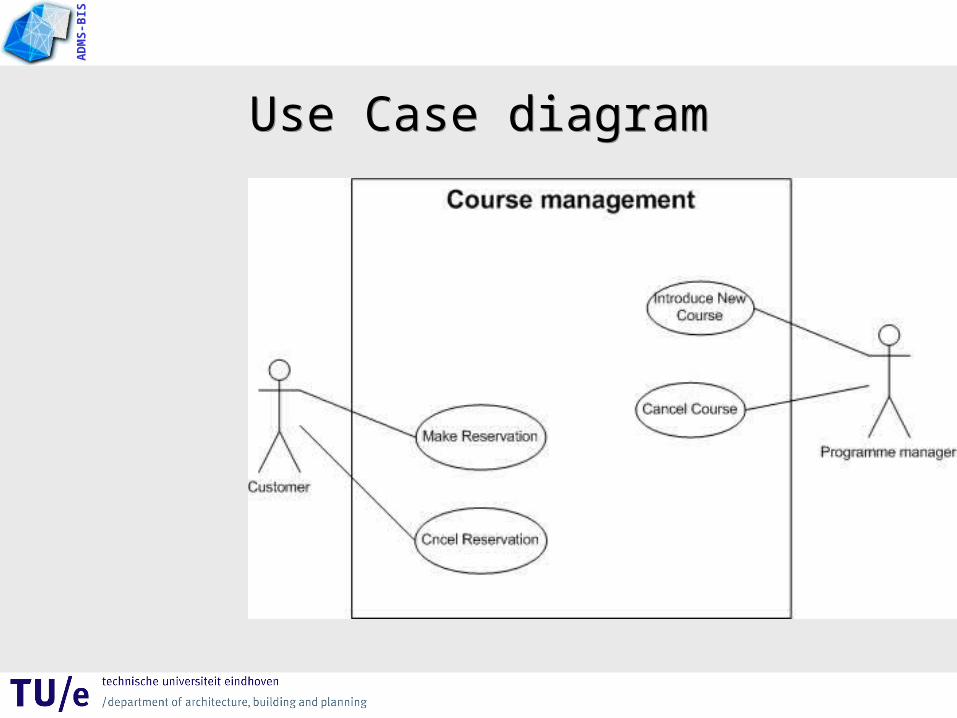
Use Case diagramUse Case diagram
AD
MS
-BIS
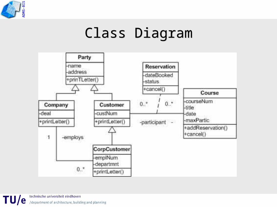
Class DiagramClass Diagram

AD
MS
-BIS
Object diagramObject diagram
AD
MS
-BIS
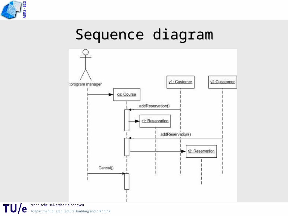
Sequence diagramSequence diagram

AD
MS
-BIS
Activity diagramActivity diagram
AD
MS
-BIS
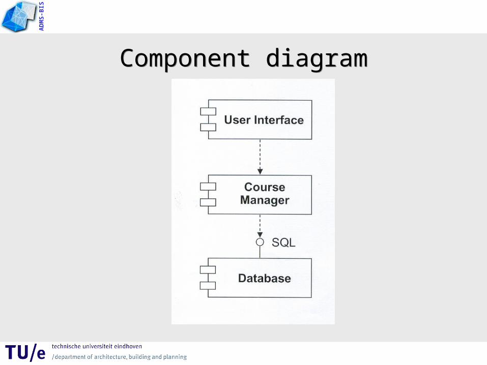
Component diagramComponent diagram
AD
MS
-BIS
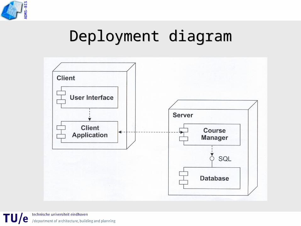
Deployment diagramDeployment diagram

AD
MS
-BIS
UML: what we will coverUML: what we will cover
• Use case diagrams– Documenting the system’s behaviour from the user’s
viewpoint, requirements capture
• Activity diagrams– Describing the sequencing of activities with support for
both conditional and parallel behaviour
• Class diagrams– Describing the type of objects in a system and the static
relationships between them
AD
MS
-BIS
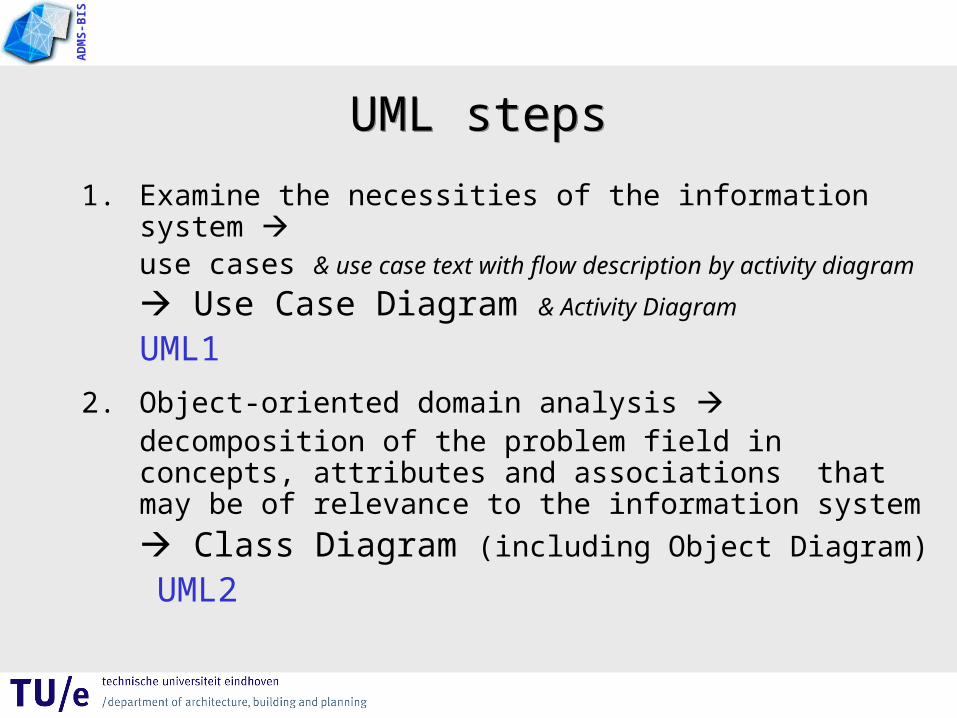
UML stepsUML steps
1. Examine the necessities of the information system use cases & use case text with flow description by activity diagram
Use Case Diagram & Activity Diagram
UML1
2. Object-oriented domain analysis decomposition of the problem field in concepts, attributes and associations that may be of relevance to the information system
Class Diagram (including Object Diagram)
UML2
AD
MS
-BIS
Activity DiagramActivity Diagram

AD
MS
-BIS
ExampleExample

AD
MS
-BIS
Activity Diagram: what is it?Activity Diagram: what is it?
• Describes activities and flows of data or decisions between activities
• Provides a very broad view of business processes
• Can be used to break out the activities that occur within a use case
• Good for showing parallel threads
AD
MS
-BIS
Activity Diagram: what is it?Activity Diagram: what is it?
• Describes activities and flows of data or decisions between activities
• Can be used to break out the activities that occur within a use case

AD
MS
-BIS
Activity Diagram: when to use it?Activity Diagram: when to use it?
• When describing work flow across many use cases
• When analysing a use case, and assigning scenario’s
• When dealing with multi-threaded applications
AD
MS
-BIS
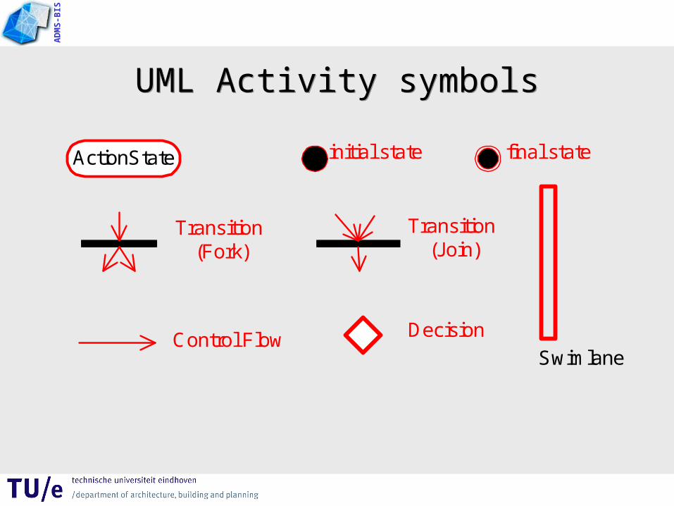
UML Activity symbolsUML Activity symbols
ActionState initial state final state
Transition (Fork)
Transition (Join)
Control Flow Decision
Swimlane

AD
MS
-BIS
Action StateAction State
• In a conceptual diagram an activity is a task that needs to be done – either by a human or a computer
• In a specification-perspective diagram or an implementation-diagram, an activity is a method on a class
AD
MS
-BIS
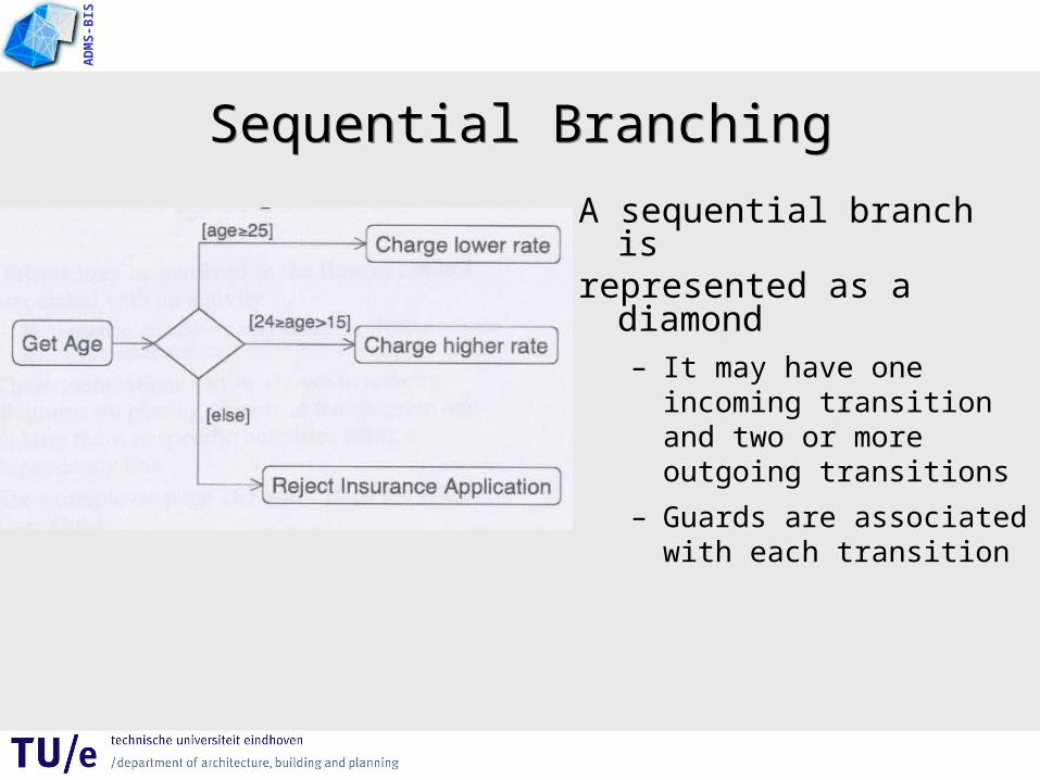
Sequential BranchingSequential Branching
A sequential branch isrepresented as a diamond
– It may have one incoming transition and two or more outgoing transitions
– Guards are associated with each transition

AD
MS
-BIS
Branch & MergeBranch & MergeCalculate Risk
Issue a Loan
[ risk low]
Ask for Authorization
Continue
[ risk high]
AD
MS
-BIS
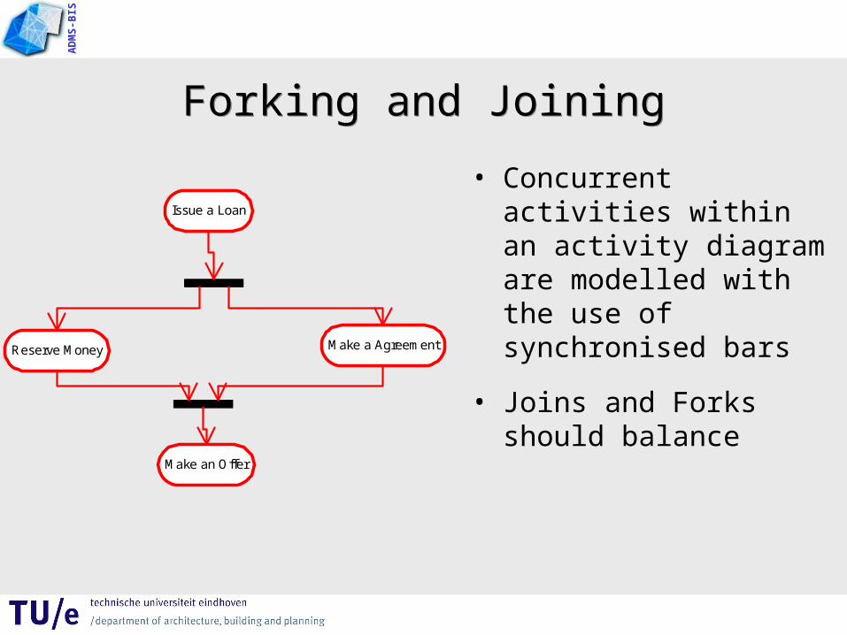
Forking and JoiningForking and Joining
• Concurrent activities within an activity diagram are modelled with the use of synchronised bars
• Joins and Forks should balance
Issue a Loan
Reserve Money Make a Agreement
Make an Offer
AD
MS
-BIS
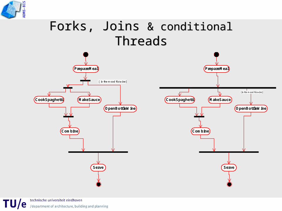
Forks, Joins & conditional ThreadsForks, Joins & conditional Threads
PrepareMeal
CookSpaghetti MakeSauce
Combine
OpenBottleWine
[ in the mood for wine]
Serve
PrepareMeal
CookSpaghetti MakeSauce
Combine
OpenBottleWine
Serve
[ in the mood for wine]

AD
MS
-BIS
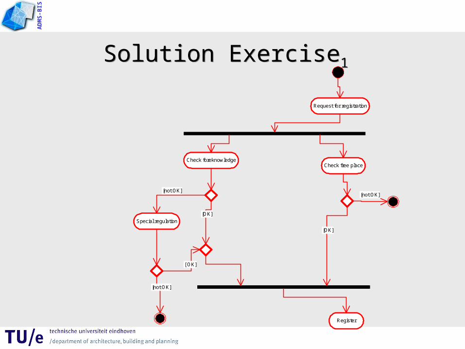
Exercise1 Activity DiagramExercise1 Activity Diagram
Make an activity diagram of the following situation:At a course administration department a student makes a
request for registering a course.
Prior to an actual registration, the foreknowledge of the student is checked. Concurrent, there is a check whether the course is full or not. If the foreknowledge of the student is ok, there is a registration if possible. Otherwise, the possibilities for a special regulation will be explored. Is a special regulation possible, there is a registration too (if possible).
AD
MS
-BIS
Solution Exercise1 Solution Exercise1
Request for registration
Check foreknowledgeCheck free place
Special regulation
Register
[not OK]
[not OK]
[OK]
[not OK]
[OK]
[ OK]

AD
MS
-BIS
Swim lanesSwim lanes
• The activities of an activity diagram may be performed by different groups.
• Each zone or lane represents the responsibilities of a particular group.
AdministrationDeskFinance
Issue a Loan
Reserve Money Make a Agreement
Make an Offer

AD
MS
-BIS
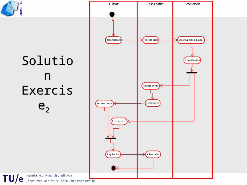
Exercise2 Activity DiagramExercise2 Activity Diagram
Make an activity diagram including swimlanes of the
following situation:
A client places an order for a product at a company.
The sales department will process the order and subsequently the stockroom assembles the ordered goods and dispatches the order.
As a result of the order and after the message of the stockroom that the order is dispatched, a receipt and an invoice are sending parallel to the client.
The sales department prepares the invoice.
If, subsequently, the client has paid the invoice, the sales department completes the order.
AD
MS
-BIS
Solution Exercise2 Solution
Exercise2
StockroomSales officeClient
Order product Process order Assemble ordered goods
Dispatch order
Prepare invoice
Send invoiceReceive invoice
Receive order
Pay invoice Close order
AD
MS
-BIS
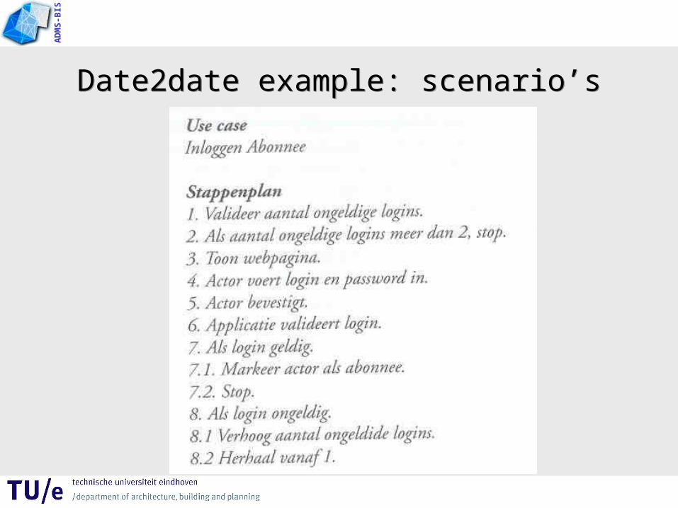
Date2date example: scenario’sDate2date example: scenario’s

AD
MS
-BIS
Use Case Inloggen abonnee
Actors Abonnee, bezoeker
Description
Pre-conditions
Checken op geldigheid actor als abonnee
----
Basic flow 1. Valideer aantal ongeldige logins
2. Toon webpagina login
3. Actor voert login en password in
4. Actor bevestigt
5. Applicatie valideert login
6. Markeer actor als abonnee
Extension /
Exception flow 1a Login ongeldig
1a1 Aantal ongeldige logins >2, stop
5a Login ongeldig
5a1 Verhoog aantal ongeldig logins, herhaal 1
Post-conditions Actor is bekend als abonnee en is ingelogd
Date2date : Inloggen abonnee – use case textDate2date : Inloggen abonnee – use case text

AD
MS
-BIS
Date2date : Inloggen abonnee – activity diagram
Date2date : Inloggen abonnee – activity diagram
Valideer aantal ongeldige logins
[login ongeldig]
Webpagina inloggen abonnee
[aantal ongeldige logins <= 2]
Actor voert login en password in
Actor bevestigt
Applicatie valideert login
Markeer actor als abonnee
[login en password geldig]
Verhoog aantal ongeldige logins
[login ongeldig]
AD
MS
-BIS
Key pointKey point
• Activity diagrams are useful for– Business Process Redesign– Work Flow Modeling
– Analysing Use Cases

AD
MS
-BIS
NS Ticket serviceNS Ticket service
• Make an activity diagram for the actor ‘Traveller’.
• Describe an use case.
Take ticket
Destination
Single / Retour
No Reduction / 40% reduction
2e class / 1e class

AD
MS
-BIS
Use Case diagram ‘NS Ticket service’Use Case diagram ‘NS Ticket service’
Traveller
Buy OV ticket
Buy NS ticket
Pay ticket
«extends»
«uses»
AD
MS
-BIS
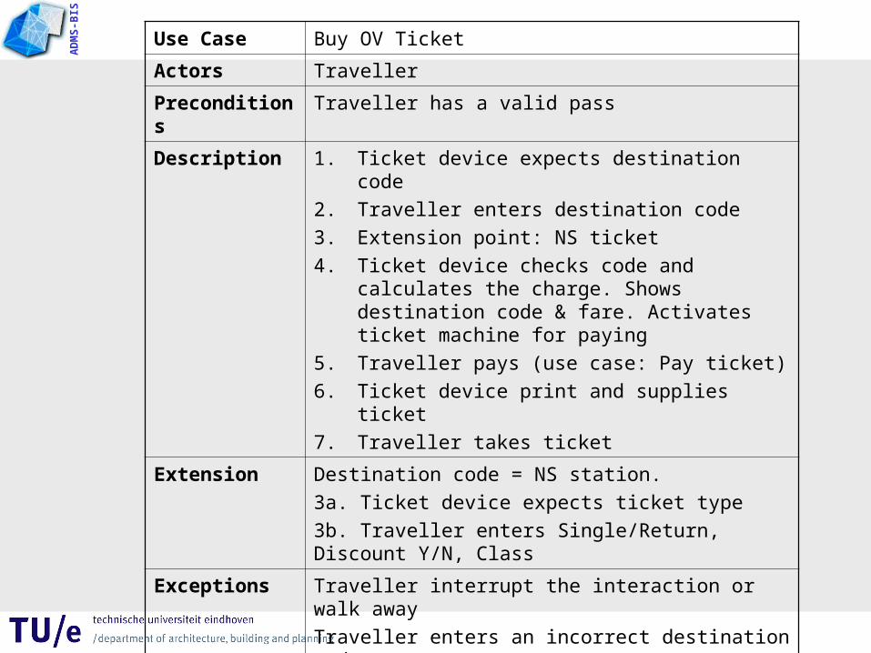
Use Case Buy OV Ticket
Actors Traveller
Preconditions Traveller has a valid pass
Description 1. Ticket device expects destination code
2. Traveller enters destination code
3. Extension point: NS ticket
4. Ticket device checks code and calculates the charge. Shows destination code & fare. Activates ticket machine for paying
5. Traveller pays (use case: Pay ticket)
6. Ticket device print and supplies ticket
7. Traveller takes ticket
Extension Destination code = NS station.
3a. Ticket device expects ticket type
3b. Traveller enters Single/Return, Discount Y/N, Class
Exceptions Traveller interrupt the interaction or walk away
Traveller enters an incorrect destination code
Payment is not finished off successful
Result Traveller has ticket.
(NS can look forward to the payment)
AD
MS
-BIS
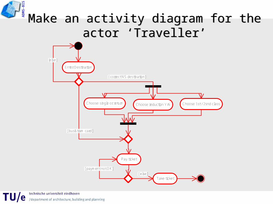
Make an activity diagram for the actor ‘Traveller’
Make an activity diagram for the actor ‘Traveller’
Enter Destination
[else]
[ correct NS destination]
Choose single or return Choose reduction Y/N Choose 1st / 2snd class
[ bus&tram card]
Pay ticket
[ payment not OK]
Take ticket[ else]
AD
MS
-BIS
Microsoft VisioMicrosoft Visio

AD
MS
-BIS
Microsoft VisioMicrosoft Visio
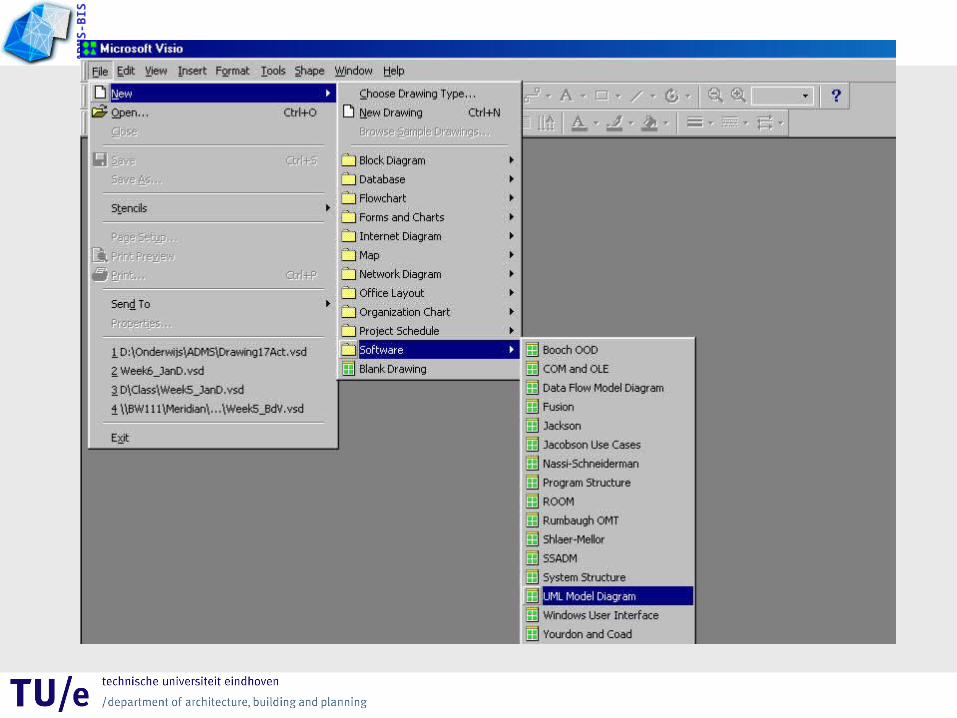
Install Microsoft Visio via
http://w3.tue.nl/nl/diensten/dienst_ict/producten_en_diensten/
dan:• PC Software InstallatiePC Software Installatie
•Grafische ApplicatiesGrafische Applicaties•MS Visio ProfessionalMS Visio Professional
AD
MS
-BIS

AD
MS
-BIS

AD
MS
-BIS
Task UML part 1
Task UML part 1
AD
MS
-BIS
Task (opdracht) deelresultaat 2 Task (opdracht) deelresultaat 2
Starting point: IS of your subject• Make Use Case Diagram of the intended
information system• Describe the use cases with a use case text• Make activity diagrams of the descriptions of the
scenario’s of the use cases (from the use case text)