Admiral Pool Lift - medicaleshop.com
16
Copyright © 2019 Aqua Creek Products All Rights Reserved Revised 8/26/19 Admiral Pool Lift Check entire box and all packing materials for parts. Before beginning assembly, read the instructions and identify parts using the fgures and parts listed in this document. It is critical that all parts be carefully inspected prior to installation. If any damage occurred in transit, Aqua Creek Products, LLC must be notifed within three days of receipt of unit. Proper installation cannot be overstressed, as an improper installation voids Aqua Creek’s warranty and may affect the safety of the user. READ CAREFULLY PART #: F-ADMRL-04 US PATENT NUMBER: [D507,769 S] 450 LB. [204 kg] MAXIMUM WEIGHT CAPACITY FOR INDOOR OR OUTDOOR USE MANDATORY LEAVE THIS MANUAL WITH LIFT OWNER ADA COMPLIANT 1
Transcript of Admiral Pool Lift - medicaleshop.com

Copyright © 2019 Aqua Creek Products All Rights Reserved Revised 8/26/19
AdmiralPool Lift
Check entire box and all packing materials for parts. Before beginning assembly, read the instructionsandidentifypartsusingthefiguresandpartslistedinthisdocument.
It is critical that all parts be carefully inspected prior to installation. If any damage occurred in transit,AquaCreekProducts,LLCmustbenotifiedwithinthreedaysofreceiptofunit.
Proper installation cannot be overstressed, as an improper installation voids Aqua Creek’s warrantyandmayaffectthesafetyoftheuser.
READ CAREFULLY
PART #: F-ADMRL-04US PATENT NUMBER: [D507,769 S]
450 LB. [204 kg] MAXIMUM WEIGHT CAPACITY
FOR INDOOR OR OUTDOOR USE
MANDATORY LEAVE THIS MANUAL WITH LIFT OWNER
ADA COMPLIANT
1

Copyright © 2019 Aqua Creek Products All Rights Reserved Revised 8/26/19
IMPORTANT SAFETY INSTRUCTIONS
Wheninstallingandusingthiselectricalappliance,basicprecautionsshouldalwaysbe followed,includingthefollowing:
READ ALL INSTRUCTIONS BEFORE USING
WARNING - To reduce the risk of injury, do not permit children to use this product unless they are closely supervised at all times.
Thisapplianceisnotintendedforusebypersons(includingchildren)withreducedphysical,sensoryormentalcapabilities,orlackofexperienceandknowledge,unlesstheyhavebeengivensupervisionorinstruction concerning use of the appliance by a person responsible for their safety.
Awireconnectorisprovidedontheunittoconnectaminimum8AWG(8.4mm2) solid copper conductor betweenthisunitandthemeansforlocalequipotentialbonding.
Checktheunitperiodicallyforsignsofdeterioration:Keepallnuts,boltsandscrewstighttobesuretheliftisinsafeworkingcondition.
SAVE THESE INSTRUCTIONS
AffixsuppliedADAPOOL/SPALIFTsigninalocationvisiblefromtheliftatalltimes.
Rechargeable batteries are to be removed from the appliance before being charged. Batteries are to be insertedwiththecorrectpolarity.Iftheapplianceistobestoredunusedforalongperiodoftime,thebatteries should be removed. The supply terminals are not to be short-circuited.
REDUCE THE RISK OF DROWNING!
Supervise children at all times.
No jumping or diving from the lift.
Seatmaybehot,usecautionwhenentering.
Keepcoveredwhennotinuse.Inspectandcleanbeforeuse.
INDOOR BATTERY CHARGER:AMPERAGE = 0.65 FREQUENCY = 60
24 VOLT BATTERY AMPERAGE=8IPRATING=IPX5
Admiral Lift
2
Copyright © 2019 Aqua Creek Products All Rights Reserved Revised 8/26/19
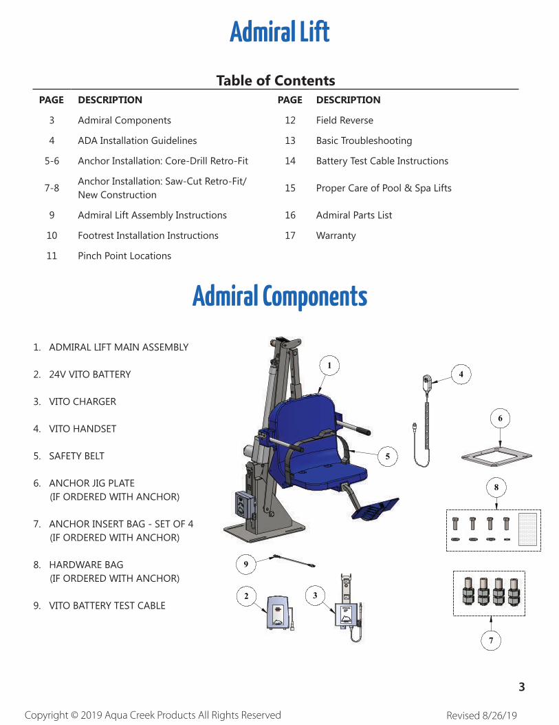
Admiral Components
1. ADMIRAL LIFT MAIN ASSEMBLY
2. 24V VITO BATTERY
3. VITO CHARGER
4. VITO HANDSET
5. SAFETY BELT
6. ANCHOR JIG PLATE
(IF ORDERED WITH ANCHOR)
7. ANCHOR INSERT BAG - SET OF 4
(IF ORDERED WITH ANCHOR)
8.HARDWAREBAG (IF ORDERED WITH ANCHOR)
9. VITO BATTERY TEST CABLE
Admiral Lift
Table of Contents
PAGE DESCRIPTION PAGE DESCRIPTION
3 Admiral Components 12 Field Reverse
4 ADA Installation Guidelines 13 Basic Troubleshooting
5-6 Anchor Installation: Core-Drill Retro-Fit 14 Battery Test Cable Instructions
7-8AnchorInstallation:Saw-CutRetro-Fit/NewConstruction
15 Proper Care of Pool & Spa Lifts
9 Admiral Lift Assembly Instructions 16 Admiral Parts List
10 Footrest Installation Instructions 17 Warranty
11 Pinch Point Locations
2 3
9
6
4
7
1
5
8
3
Copyright © 2019 Aqua Creek Products All Rights Reserved Revised 8/26/19
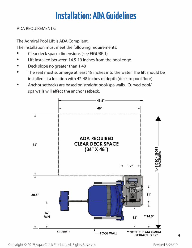
Installation: ADA GuidelinesADA REQUIREMENTS:
The Admiral Pool Lift is ADA Compliant.
The installation must meet the following requirements:
• Clear deck space dimensions (see FIGURE 1)
• Lift installed between 14.5-19 inches from the pool edge
• Deck slope no greater than 1:48
• The seat must submerge at least 18 inches into the water. The lift should be
installed at a location with 42-48 inches of depth (deck to pool fl oor)
• Anchor setbacks are based on straight pool/spa walls. Curved pool/
spa walls will eff ect the anchor setback.
11"
36"
48"
30.5"
13" **14.5"
12"
16”MIN
49.5”
POOL WALL **NOTE: THE MAXIMUM SETBACK IS 19"
ADA REQUIREDCLEAR DECK SPACE
(36" X 48")1:
48 D
ECK
SLO
PEM
AXI
MUM
FIGURE 14

Copyright © 2019 Aqua Creek Products All Rights Reserved Revised 8/26/19
1. Mark the 4 hole locations on your deck using
the larger holes of the anchor jig plate as a
template. For ADA compliance, confirm the center
of the jig plate front holes are 14.5 to 19 inches
from the pool’s edge. SEE FIGURE 2
2. Drill the 4 hole locations to 4 1/2 inches deep
using the 1 1/2 inch drill bit. Clear all debris and
ensure holes are completely dry.
NOTE: Create a depth marker on the drill bit with black
electrical tape to make sure you drill to the right depth.
NOTE: Local bonding regulations may require you to drill one hole larger than the others in order to bond at least
one of the anchor inserts. You may need to saw cut a portion of your deck.
See “Saw Cutting Retro-Fit Instructions” on page 6.
3. Remove the nuts and the black protective coverings from the threaded anchor inserts.
Anchor Installation: Core-Drill Retro-FitNOTE: FOR DECKS 6” THICK OR MORE, 2500PSI MINIMUM STRENGTH CONCRETE REQUIRED
You will need:
• Core drill and 1½” core drill bit• Tape measure• Marking pen• Hammer• Cold chisel• Torpedo level• High strength 2-part construction epoxy*• Masking tape• Black electrical tape (optional)• Anti-seize packet
*Aqua Creek recommends either Hilti™ Brand HIT RE-500-SD or Simpson™ brand SET-XP or equivalent
(not included) Anchor jig plate with hardware
FIGURE 2
5
Copyright © 2019 Aqua Creek Products All Rights Reserved Revised 8/26/19
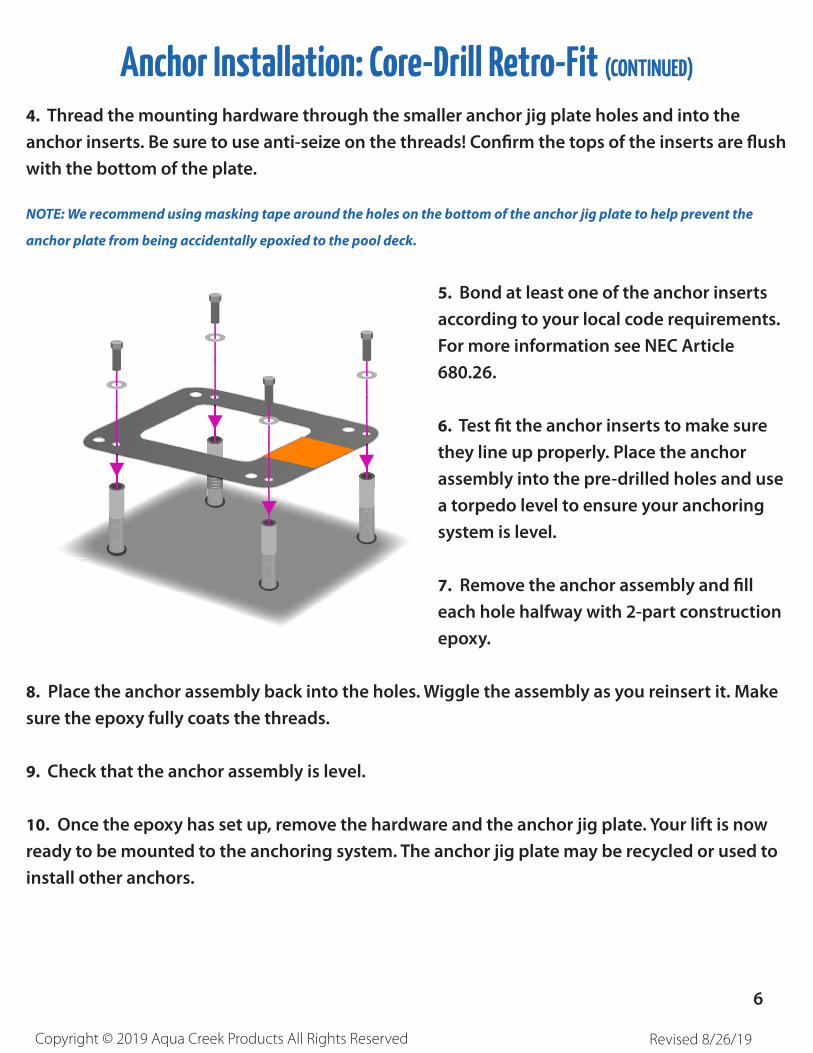
4. Thread the mounting hardware through the smaller anchor jig plate holes and into the
anchor inserts. Be sure to use anti-seize on the threads! Confirm the tops of the inserts are flush
with the bottom of the plate.
NOTE: We recommend using masking tape around the holes on the bottom of the anchor jig plate to help prevent the
anchor plate from being accidentally epoxied to the pool deck.
5. Bond at least one of the anchor inserts
according to your local code requirements.
For more information see NEC Article
680.26.
6. Test fit the anchor inserts to make sure
they line up properly. Place the anchor
assembly into the pre-drilled holes and use
a torpedo level to ensure your anchoring
system is level.
7. Remove the anchor assembly and fill
each hole halfway with 2-part construction
epoxy.
8. Place the anchor assembly back into the holes. Wiggle the assembly as you reinsert it. Make
sure the epoxy fully coats the threads.
9. Check that the anchor assembly is level.
10. Once the epoxy has set up, remove the hardware and the anchor jig plate. Your lift is now
ready to be mounted to the anchoring system. The anchor jig plate may be recycled or used to
install other anchors.
Anchor Installation: Core-Drill Retro-Fit (CONTINUED)
6

Copyright © 2019 Aqua Creek Products All Rights Reserved Revised 8/26/19
Anchor Installation: Saw-Cut Retro-Fit
1. Remove 1 nut from each anchor insert. Place the anchor
inserts through the larger hole of the anchor jig plate.
Thread the removed nuts back onto the anchor inserts. The
anchor plate should be sandwiched between the two nuts
on each anchor insert. SEE FIGURE A
2. Mark out a section of the pool deck that you are removing. Plan on removing at least
4 feet 0 inches by 4 feet 0 inches.
3. Cut along your marks with a diamond blade
concrete saw.
4. Using the sledge hammer break up the concrete
within the cut area and remove the pieces.
5. Install rebar in the open area of the deck. Tie the
rebar into the existing deck if possible. SEE FIGURE B
6. Set the anchor system in place. For ADA compliance
and clearance, make sure the center of the large
anchor jig plate hole is between 14.5 and 19 inches
from the pool’s edge. SEE FIGURE C, PAGE 7
7. Using the string line or a straight edge, confi rm the top of each anchor body is level with the
FINISHED deck surface. Each anchor body can be individually adjusted by turning the nuts with a
large wrench.
8. Bond the anchoring system according to your local code requirements by using the bonding
lug on the anchor plate. SEE FIGURE C, PAGE 7 (See NEC Article 680.26)
9. Pour concrete and fi nish the pool deck surface. SEE FIGURE A
10. Once the concrete has cured, the lift is ready to be mounted to the anchoring system.
FIGURE B
Bonding Lug• Concrete saw with diamond blade• Tape measure• 4’ long straight edge or chalk line• Sledge hammer• Cold chisel
• Torpedo level• String Line• Concrete & concrete fi nishing tools• #5 rebar
You Will Need:
FIGURE A
7

Copyright © 2019 Aqua Creek Products All Rights Reserved Revised 8/26/19
1. Remove 1 nut from each anchor insert. Place the anchor inserts through the larger hole
of the anchor jig plate. Thread the removed nuts back onto the anchor inserts. The anchor
plate should be sandwiched between the two nuts on each anchor insert.
SEE FIGURE A, PAGE 6
2. Install rebar in the open area of the deck.SEE FIGURE B, PAGE 6
3. Set the anchor system in place. For ADA compliance and clearance, make sure the
center of the large anchor jig plate holes are between 14.5 and 19 inches from the pool’s
edge. SEE FIGURE C
4. Make sure the top of each anchor body is
fl ush with the FINISHED deck surface. Each
anchor body can be adjusted individually by
turning the nuts with a large wrench.
5. Bond the anchoring system by using the
bonding lug on the anchor jig plate. Bond
the system according to your local code
requirements. (See NEC Article 680.26)
SEE FIGURE C
6. Pour your concrete and fi nish the pool
deck surface.
SEE FIGURE A, PAGE 6
7. Once the concrete has cured the lift
is ready to be mounted to the anchoring
system.
NOTE: For installations where a new deck is being poured, or where a dedicated pad is being poured
just for the pool lift, the concrete must satisfy the ADA requirements outlined on page 3 of this manual.
Your pool deck must be at least 4 feet - 0 inches long by 4 feet - 0 inches wide by 6 inches thick. It must be reinforced with 5 sticks of #5 rebar each way, 2 inches clear (min) from the top and bottom of the footing.
Anchor Installation: New Construction
4"
6"
FLUSH W-DECK
#5 REBAR E-W (5 PCS)DRILL & EPOXY INTO EXISTING
SLAB (4" MIN EMBED)
2500PSI MIN
48"
2.5"MIN
14.5" TO 19"SETBACK
48"
LABEL
BONDING-LUG
POOLWALL
8-AWG SOLID-COPPER WIRE(ATTACH TO BONDING-GRID)
#5REBAR
*[37 TO 48cm]
*SETBACK DIMENSIONS ARE FOR FLAT DECK APPLICATIONS. FOR SLOPED DECKS OR OTHER FEATURES, CONTACT AQUA CREEK BEFORE INSTALLATION.
FIGURE C
8
Copyright © 2019 Aqua Creek Products All Rights Reserved Revised 8/26/19
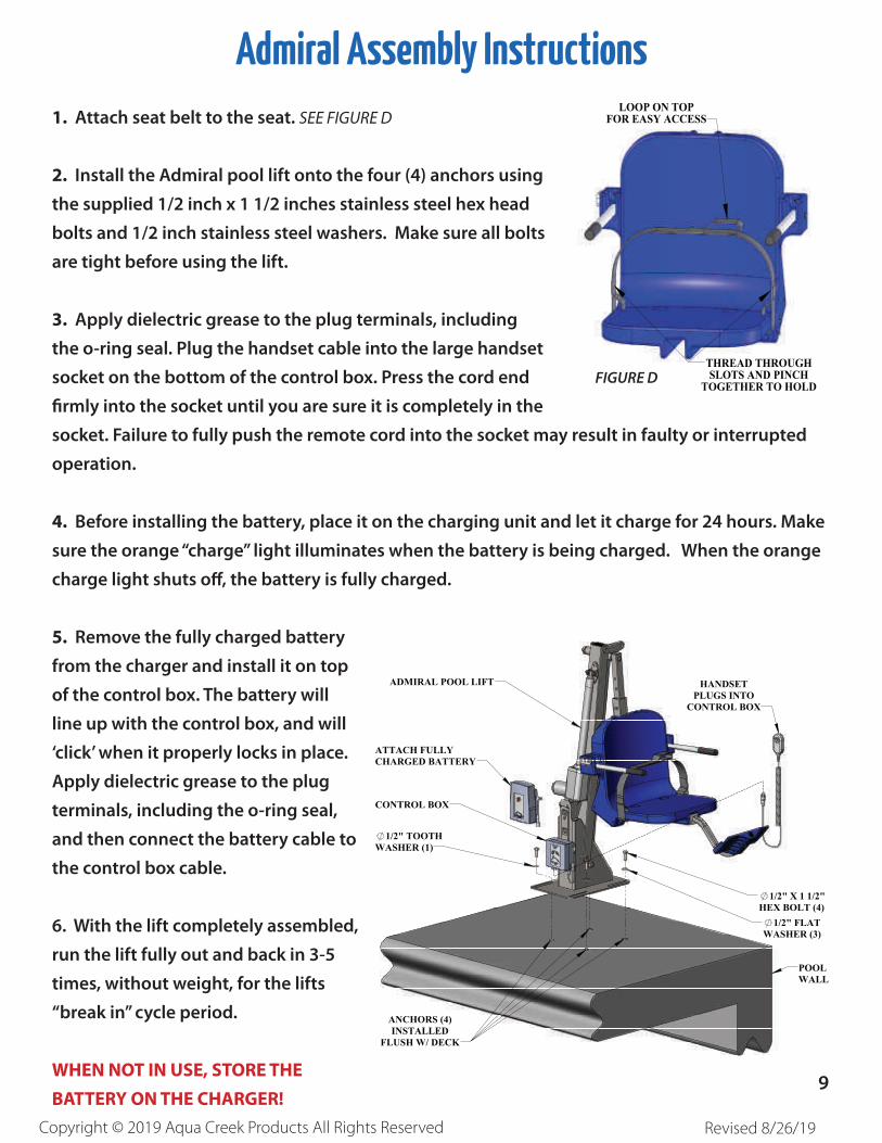
Admiral Assembly Instructions
1. Attach seat belt to the seat. SEE FIGURE D
2. Install the Admiral pool lift onto the four (4) anchors using
the supplied 1/2 inch x 1 1/2 inches stainless steel hex head
bolts and 1/2 inch stainless steel washers. Make sure all bolts
are tight before using the lift.
3. Apply dielectric grease to the plug terminals, including
the o-ring seal. Plug the handset cable into the large handset
socket on the bottom of the control box. Press the cord end
fi rmly into the socket until you are sure it is completely in the
socket. Failure to fully push the remote cord into the socket may result in faulty or interrupted
operation.
4. Before installing the battery, place it on the charging unit and let it charge for 24 hours. Make
sure the orange “charge” light illuminates when the battery is being charged. When the orange
charge light shuts off , the battery is fully charged.
5. Remove the fully charged battery
from the charger and install it on top
of the control box. The battery will
line up with the control box, and will
‘click’ when it properly locks in place.
Apply dielectric grease to the plug
terminals, including the o-ring seal,
and then connect the battery cable to
the control box cable.
6. With the lift completely assembled,
run the lift fully out and back in 3-5
times, without weight, for the lifts
“break in” cycle period.
WHEN NOT IN USE, STORE THE BATTERY ON THE CHARGER!
LOOP ON TOPFOR EASY ACCESS
THREAD THROUGHSLOTS AND PINCH
TOGETHER TO HOLDFIGURE D
POOLWALL
ANCHORS (4)INSTALLED
FLUSH W/ DECK
1/2" X 1 1/2"HEX BOLT (4)
1/2" FLATWASHER (3)
HANDSETPLUGS INTO
CONTROL BOX
ADMIRAL POOL LIFT
ATTACH FULLYCHARGED BATTERY
CONTROL BOX
1/2" TOOTHWASHER (1)
9

Copyright © 2019 Aqua Creek Products All Rights Reserved Revised 8/26/19
Footrest Installation InstructionsThe Aqua Creek footrest assembly is designed to fi t under the chair and is installed inside the 2”
square tubing that supports the chair from underneath. To install the footrest;
1. Insert the footrest assembly into the 2 x 2 square tubing that supports the chair until the
plastic insert of the footrest assembly sits fl ush against the end of the 2 x 2 tube.
2. Using the supplied 1/4” hardware, fasten the legrest assembly to the 2 x 2 tubing using a 5/32”
allen wrench.
1/4" FLAT WASHER1/4" LOCK WASHER1/4" X 1/2" BUTTON-HEAD
FOOTREST ASSEMBLY
FOOTREST IN FOOTREST OUT
10
Copyright © 2019 Aqua Creek Products All Rights Reserved Revised 8/26/19
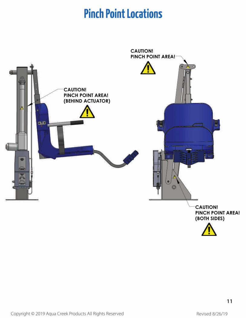
Pinch Point Locations
CAUTION!PINCH POINT AREA!
CAUTION!PINCH POINT AREA!(BOTH SIDES)
CAUTION!PINCH POINT AREA!(BEHIND ACTUATOR)
11
Copyright © 2019 Aqua Creek Products All Rights Reserved Revised 8/26/19
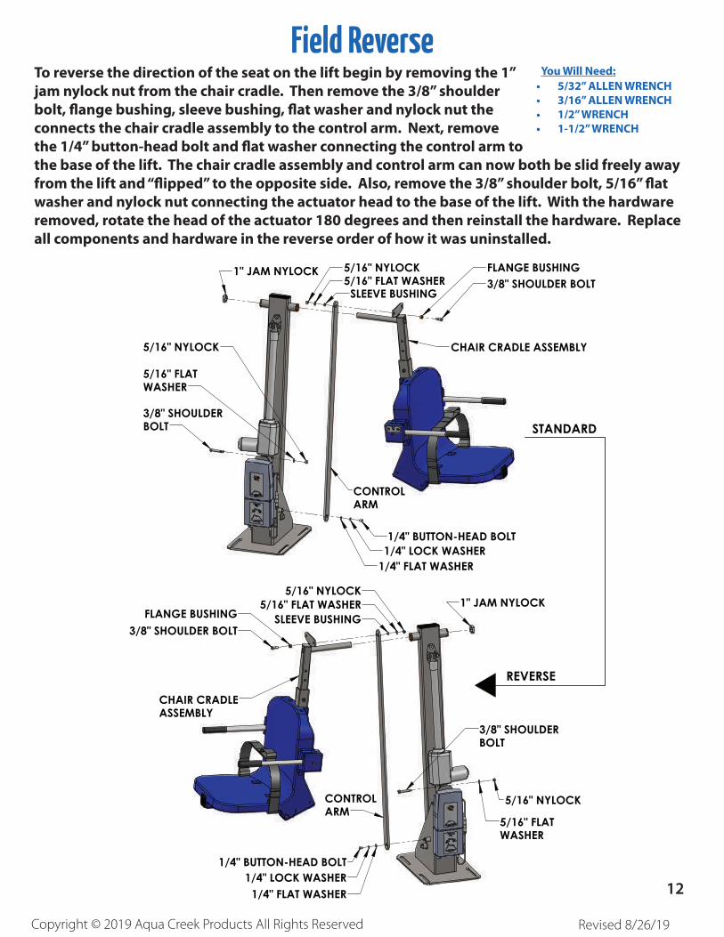
Field ReverseTo reverse the direction of the seat on the lift begin by removing the 1” jam nylock nut from the chair cradle. Then remove the 3/8” shoulder bolt, fl ange bushing, sleeve bushing, fl at washer and nylock nut the connects the chair cradle assembly to the control arm. Next, remove the 1/4” button-head bolt and fl at washer connecting the control arm to the base of the lift. The chair cradle assembly and control arm can now both be slid freely away from the lift and “fl ipped” to the opposite side. Also, remove the 3/8” shoulder bolt, 5/16” fl at washer and nylock nut connecting the actuator head to the base of the lift. With the hardware removed, rotate the head of the actuator 180 degrees and then reinstall the hardware. Replace all components and hardware in the reverse order of how it was uninstalled.
• 5/32” ALLEN WRENCH• 3/16” ALLEN WRENCH• 1/2” WRENCH• 1-1/2” WRENCH
You Will Need:
1" JAM NYLOCK 5/16" NYLOCK5/16" FLAT WASHER
SLEEVE BUSHING
FLANGE BUSHING3/8" SHOULDER BOLT
CHAIR CRADLE ASSEMBLY
CONTROLARM
1/4" BUTTON-HEAD BOLT1/4" LOCK WASHER
1/4" FLAT WASHER
3/8" SHOULDERBOLT
5/16" FLATWASHER
5/16" NYLOCK
REVERSE
STANDARD
5/16" NYLOCK
5/16" FLATWASHER
3/8" SHOULDERBOLT
1" JAM NYLOCK
1/4" BUTTON-HEAD BOLT1/4" LOCK WASHER
1/4" FLAT WASHER
CONTROLARM
CHAIR CRADLEASSEMBLY
3/8" SHOULDER BOLTFLANGE BUSHING SLEEVE BUSHING
5/16" FLAT WASHER5/16" NYLOCK
12

Copyright © 2019 Aqua Creek Products All Rights Reserved Revised 8/26/19
Basic TroubleshootingProblem: The lift won’t move.
Solution:
Check the ends of the cords for corrosion or damage. The cord plugs should be recessed into the outlet. You should feel them pop into place when they are correctly inserted.
1. Make sure the cords are properly plugged in:
NOT Properly Inserted:The cord plug is flush with or sticking out of the outlet
Properly Inserted:The cord plug is recessed
into the outlet
2. Check the contact points:
Make sure the contact point of the control box and the battery are not damaged or corroded. If there is corrosion clean with Scotch-BriteTM pad. Put some dielectric grease on the contact points before reattaching the battery.
Note: If you feel your lift is malfunctioning due to a faulty battery or connections, contact Aqua Creek Products for a testing kit.
The Charger is ON when the green light is glowing
The Battery is CHARGING when the
orange light is glowing
When the Battery is fully charged the
orange light will stop glowing
3. Make sure the battery is fully charged:
Problem: The lift stopped moving and is stuck.
Solution:
Press the emergency retract button on the front of the control box to retract the lift.
Note:theliftwillnotretractif the battery is not fully charged or if the control box isnotworking.Theemergencybutton only overrides the remote handset.
1. Press the Emergency button
13

Copyright © 2019 Aqua Creek Products All Rights Reserved Revised 8/26/19
Battery Test Cable Instructions
WARNING! DO NOT ATTEMPT TO DIRECTLY PROBE THE BATTERY CONNECTOR TO TEST VOLTAGE.
THIS MAY CAUSE PERMANENT DAMAGE TO THE BATTERY! USE THE SUPPLIED BATTERY TEST CABLE
ONLY FOR CHECKING THE BATTERY VOLTAGE!
The Aqua Creek 24V battery has a cable and connector for connecting to the control box or to the
battery charger. The battery connector is not suitable to check the battery voltage, as it is very hard
to probe the connector without shorting-out the battery, which will cause damage. For this reason,
a separate battery test cable is provided. To safely check the battery voltage, use a voltmeter or
multimeter with standard test probes, and insert the probes into the test cable as shown below.
24V BATTERY
BATTERYCONNECTOR
BATTERYTEST
CABLE
MALECONNECTOR
INSERT TESTPROBES TO
CHECK VOLTAGE
14
Copyright © 2019 Aqua Creek Products All Rights Reserved Revised 8/26/19
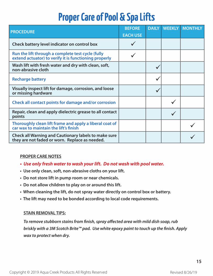
Proper Care of Pool & Spa LiftsPROCEDURE
BEFORE
EACH USE
DAILY WEEKLY MONTHLY
Check battery level indicator on control box Run the lift through a complete test cycle (fully extend actuator) to verify it is functioning properly Wash lift with fresh water and dry with clean, soft, non-abrasive cloth
Recharge battery Visually inspect lift for damage, corrosion, and loose or missing hardware
Check all contact points for damage and/or corrosion Repair, clean and apply dielectric grease to all contact points Thoroughly clean lift frame and apply a liberal coat of car wax to maintain the lift’s finish Check all Warning and Cautionary labels to make sure they are not faded or worn. Replace as needed.
PROPER CARE NOTES
• Use only fresh water to wash your lift. Do not wash with pool water.• Use only clean, soft, non-abrasive cloths on your lift.
• Do not store lift in pump room or near chemicals.
• Do not allow children to play on or around this lift.
• When cleaning the lift, do not spray water directly on control box or battery.
• The lift may need to be bonded according to local code requirements.
To remove stubborn stains from finish, spray affected area with mild dish soap, rub
briskly with a 3M Scotch Brite™ pad. Use white epoxy paint to touch up the finish. Apply
wax to protect when dry.
STAIN REMOVAL TIPS:
15
Copyright © 2019 Aqua Creek Products All Rights Reserved Revised 8/26/19
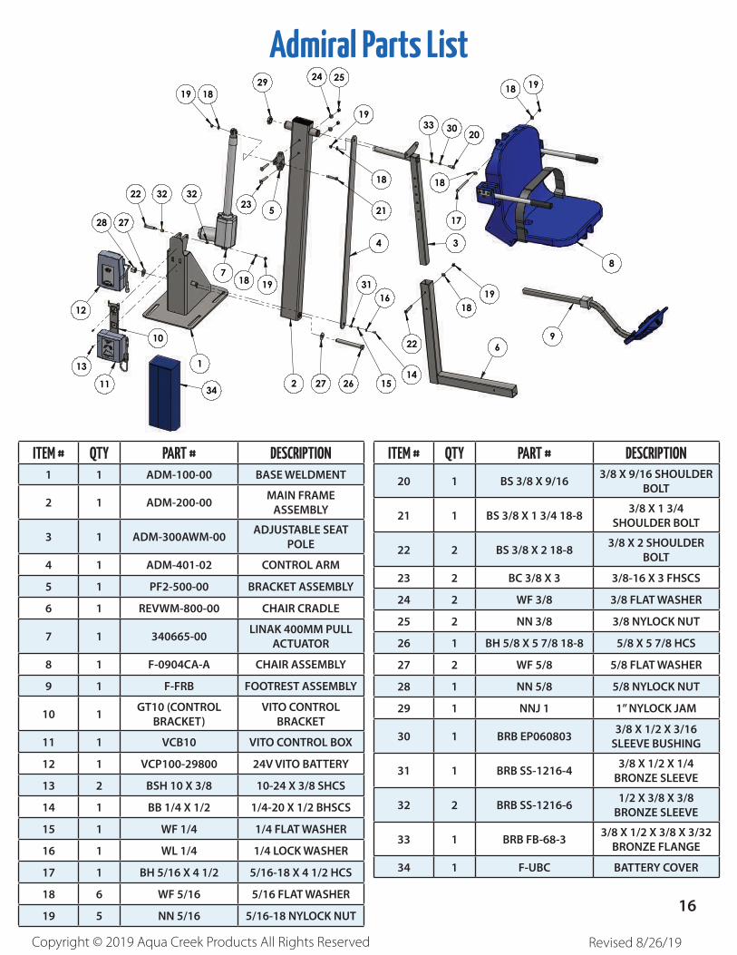
Admiral Parts List
ITEM # QTY PART # DESCRIPTION1 1 ADM-100-00 BASE WELDMENT
2 1 ADM-200-00MAIN FRAME
ASSEMBLY
3 1 ADM-300AWM-00ADJUSTABLE SEAT
POLE
4 1 ADM-401-02 CONTROL ARM
5 1 PF2-500-00 BRACKET ASSEMBLY
6 1 REVWM-800-00 CHAIR CRADLE
7 1 340665-00LINAK 400MM PULL
ACTUATOR
8 1 F-0904CA-A CHAIR ASSEMBLY
9 1 F-FRB FOOTREST ASSEMBLY
10 1GT10 (CONTROL
BRACKET)
VITO CONTROL
BRACKET
11 1 VCB10 VITO CONTROL BOX
12 1 VCP100-29800 24V VITO BATTERY
13 2 BSH 10 X 3/8 10-24 X 3/8 SHCS
14 1 BB 1/4 X 1/2 1/4-20 X 1/2 BHSCS
15 1 WF 1/4 1/4 FLAT WASHER
16 1 WL 1/4 1/4 LOCK WASHER
17 1 BH 5/16 X 4 1/2 5/16-18 X 4 1/2 HCS
18 6 WF 5/16 5/16 FLAT WASHER
19 5 NN 5/16 5/16-18 NYLOCK NUT
2627 1514
2
1918
1
11
13
12
28 27
22 32 3223 21
19
18
252429
7
19 18
9
8
17
30 20
18
18 19
5
10
31
33
4
34
16
22
1819
3
6
ITEM NO. PART NUMBER DESCRIPTION QTY.
1 ADM-100-00 ADMIRAL BASE WELDMENT 1
2 ADM-200-00 ADMIRAL MAIN FRAME ASSEMBLY 1
3 ADM-300AWM-00 ADMIRAL ADJUSTABLE CHAIR ARM WELDMENT 1
4 ADM-401-02 ADMIRAL CONTROL ARM 1
5 PF2-500-00 ADMIRAL ACTUATOR BRACKET ASSEMBLY 1
6 REVWM-800-00 CHAIR CRADLE WELDMENT 1
7 340665-00 ACTUATOR, LINAK, 400MM 1
8 F-0904CA-A CHAIR ASSEMBLY, 18" WIDE 1
9 F-FRB FOOTREST ASSEMBLY, BLUE 1
10 GT10 (CONTROL BRACKET) BRACKET, MOUNTING, VITO 1
11 VCB10 CONTROL BOX, VITO, 2-PORT, 10AMP, BATTERY LEVEL INDICATOR 1
12 VCP100-29800 BATTERY, 24V BATTERY PACK, SEALED, LEAD ACID, VITO 1
13 BSH 10 X 3-8 BOLT, 316 SS, 10-24 X 3/8 SHCS 2
14 BB 1-4 X 1-2 BOLT, 316 SS, 1/4-20 X 1/2 BHSCS 1
15 WF 1-4 WASHER, FLAT, 1/4, 316 SS 1
16 WL 1-4 LOCK WASHER, 1/4", 316 SS 1
17 BH 5-16 X 4 1-2 BOLT, 316 SS, 5/16-18 X 4 1/2 HCS 1
18 WF 5-16 WASHER, FLAT, 5/16, 316 SS 6
19 NN 5-16 NUT, 316 SS, NYLOCK, 5/16"-18 5
20 BS 3-8 X 9-16 BOLT, 316 SS, 3/8 X 9/16 SHOULDER, 5/16-18 THREAD 1
21 BS 3-8 X 1 3-4 18-8 BOLT, 18-8 SS, 3/8 X 1 3/4 SHOULDER, 5/16-18 THREAD 1
22 BS 3-8 X 2 18-8 BOLT, 18-8, 3/8 X 2 SHOULDER, 5/16-18 THREAD 2
23 BC 3-8 X 3 BOLT, 316 SS, 3/8-16 X 3 FHSCS 2
24 WF 3-8 WASHER, FLAT, 3/8, 316 SS 2
25 NN 3-8 NUT, 316 SS, NYLOCK, 3/8"-16 2
26 BH 5-8 X 5 7-8 18-8 BOLT, 18-8 SS, 5/8-11 X 5 7/8 HCS 1
27 WF 5-8 WASHER, FLAT, 5/8, 316 SS 2
28 NN 5-8 NUT, 316 SS, NYLOCK, 5/8"-11 1
29 NNJ 1 NUT, NYLOCK JAM, 316 SS, 1-8 1
30 BRB EP060803 BUSHING, BRONZE SLEEVE, EP060803, 3/8 X 1/2 X 3/16 1
31 BRB SS-1216-4 BUSHING, BRONZE SLEEVE, 3/8 X 1/2 X 1/4 1
32 BRB SS-1216-6 BUSHING, BRONZE SLEEVE, 1/2 X 3/8 X 3/8 2
33 BRB FB-68-3 BUSHING, BRONZE FLANGE, 3/8 X 1/2 X 3/8 X 3/32 1
34 F-UBC COVER, UNIVERSAL BATTERY COVER 1
ITEM # QTY PART # DESCRIPTION
20 1 BS 3/8 X 9/163/8 X 9/16 SHOULDER
BOLT
21 1 BS 3/8 X 1 3/4 18-83/8 X 1 3/4
SHOULDER BOLT
22 2 BS 3/8 X 2 18-83/8 X 2 SHOULDER
BOLT
23 2 BC 3/8 X 3 3/8-16 X 3 FHSCS
24 2 WF 3/8 3/8 FLAT WASHER
25 2 NN 3/8 3/8 NYLOCK NUT
26 1 BH 5/8 X 5 7/8 18-8 5/8 X 5 7/8 HCS
27 2 WF 5/8 5/8 FLAT WASHER
28 1 NN 5/8 5/8 NYLOCK NUT
29 1 NNJ 1 1” NYLOCK JAM
30 1 BRB EP0608033/8 X 1/2 X 3/16
SLEEVE BUSHING
31 1 BRB SS-1216-43/8 X 1/2 X 1/4
BRONZE SLEEVE
32 2 BRB SS-1216-61/2 X 3/8 X 3/8
BRONZE SLEEVE
33 1 BRB FB-68-33/8 X 1/2 X 3/8 X 3/32
BRONZE FLANGE
34 1 F-UBC BATTERY COVER
16