
AdministrAtor guide - cisco-images.cisco.com content ... When registered to a Cisco Unified...
117
Cisco TelePresence System EX Series Administrator Guide D14726.10 EX Series Administrator Guide TC6.1, APRIL 2013. www.cisco.com — Copyright © 2010–2013 Cisco Systems, Inc. All rights reserved. 1 ADMINISTRATOR GUIDE CISCO TELEPRESENCE SYSTEMS EX60 AND EX90 Software version TC6.1 APRIL 2013
Transcript of AdministrAtor guide - cisco-images.cisco.com content ... When registered to a Cisco Unified...

Cisco TelePresence System EX Series Administrator Guide
D14726.10 EX Series Administrator Guide TC6.1, APRIL 2013. www.cisco.com — Copyright © 2010–2013 Cisco Systems, Inc. All rights reserved. 1
AdministrAtor guide
CISCo TELEPRESEnCE SySTEmS EX60 AnD EX90
Software version TC6.1 APRIL 2013

Cisco TelePresence System EX Series Administrator Guide
D14726.10 EX Series Administrator Guide TC6.1, APRIL 2013. www.cisco.com — Copyright © 2010–2013 Cisco Systems, Inc. All rights reserved. 2
Thank you for choosing Cisco!
your Cisco TelePresence System EX90/EX60 has been designed to give you many years of safe, reliable operation.
This part of the EX90/EX60 documentation is aimed at administrators working with the setup of the system.
our main objective with this Administrator Guide is to address your goals and needs. Please let us know how well we succeeded!
may we recommend that you visit the Cisco web site regularly for updated versions of this guide.
The user documentation can be found on our web site. Go to: ► http://www.cisco.com/go/telepresence/docs
How to use this guide
The top menu bar and the entries in the Table of contents are all hyperlinks. you can click on them to go to the topic.
Table of contentsIntroduction ........................................................................... 3
User documentation................................................................ 4Software ................................................................................. 4What’s new in this version ...................................................... 5EX90 system overview ............................................................ 7EX60 system overview ............................................................ 8How to use the Touch controller ............................................. 9
Using the web interface .......................................................10Starting the web interface .....................................................11Changing the system password ............................................12The interactive menu .............................................................13System information ................................................................14Placing a call ......................................................................... 15Sharing content ..................................................................... 16Controlling and monitoring a call ...........................................17Local layout control ............................................................... 18Capturing snapshots ............................................................. 19managing the favorites list .................................................... 20Favorite list folders ................................................................ 21System configuration ............................................................ 22Changing system settings..................................................... 23Setting the Administrator Settings menu password ............. 24System status ....................................................................... 25Choosing a wallpaper ........................................................... 26Choosing a ringtone .............................................................. 27Peripherals overview ............................................................ 28User administration ............................................................... 29Adding a sign in banner ........................................................ 33managing the video system’s certificates............................. 34managing the list of trusted certificate authorities ............... 35Adding audit certificates ....................................................... 36Setting strong security mode ............................................... 37Deleting trust lists (CUCm only) ............................................ 38Troubleshooting .................................................................... 39Downloading log files ............................................................ 40Upgrading the system software .............................................41Backup and restore ............................................................... 42Factory reset ......................................................................... 43Restarting the system ........................................................... 44
System settings .................................................................. 45overview of the system settings .......................................... 46Audio settings ....................................................................... 49Cameras settings ...................................................................51Conference settings ............................................................. 53FacilityService settings ......................................................... 58H323 settings ........................................................................ 59network settings ................................................................... 62networkServices settings ..................................................... 69Phonebook settings .............................................................. 73Provisioning settings ..............................................................74RTP settings .......................................................................... 76Security settings ................................................................... 77SerialPort settings ................................................................. 79SIP settings ........................................................................... 80Standby settings ................................................................... 83SystemUnit settings .............................................................. 84Time settings ........................................................................ 86UserInterface settings ........................................................... 87Video settings ....................................................................... 88Experimental settings ........................................................... 99
Setting passwords ............................................................ 100Setting the system password ..............................................101Setting the menu password ................................................ 102
Appendices ........................................................................103Cisco VCS provisioning....................................................... 104Audio outputs and microphones ......................................... 105optimal definition profiles ................................................... 106ClearPath — Packet loss resilience ..................................... 107EX90 dimensions ................................................................ 108EX60 dimensions - wall mounting and arm mounting ........ 109Factory resetting ..................................................................110Factory resetting the Touch 8” controller ............................111Technical specifications .......................................................112Supported RFCs ..................................................................115User documentation on the Cisco web site .........................116
Cisco contacts ................................................................... 117

Cisco TelePresence System EX Series Administrator Guide
D14726.10 EX Series Administrator Guide TC6.1, APRIL 2013. www.cisco.com — Copyright © 2010–2013 Cisco Systems, Inc. All rights reserved. 3
CHAPTER 1
introduction
Cisco TelePresence System EX Series Administrator Guide
D14726.10 EX Series Administrator Guide TC6.1, APRIL 2013. www.cisco.com — Copyright © 2010–2013 Cisco Systems, Inc. All rights reserved. 4
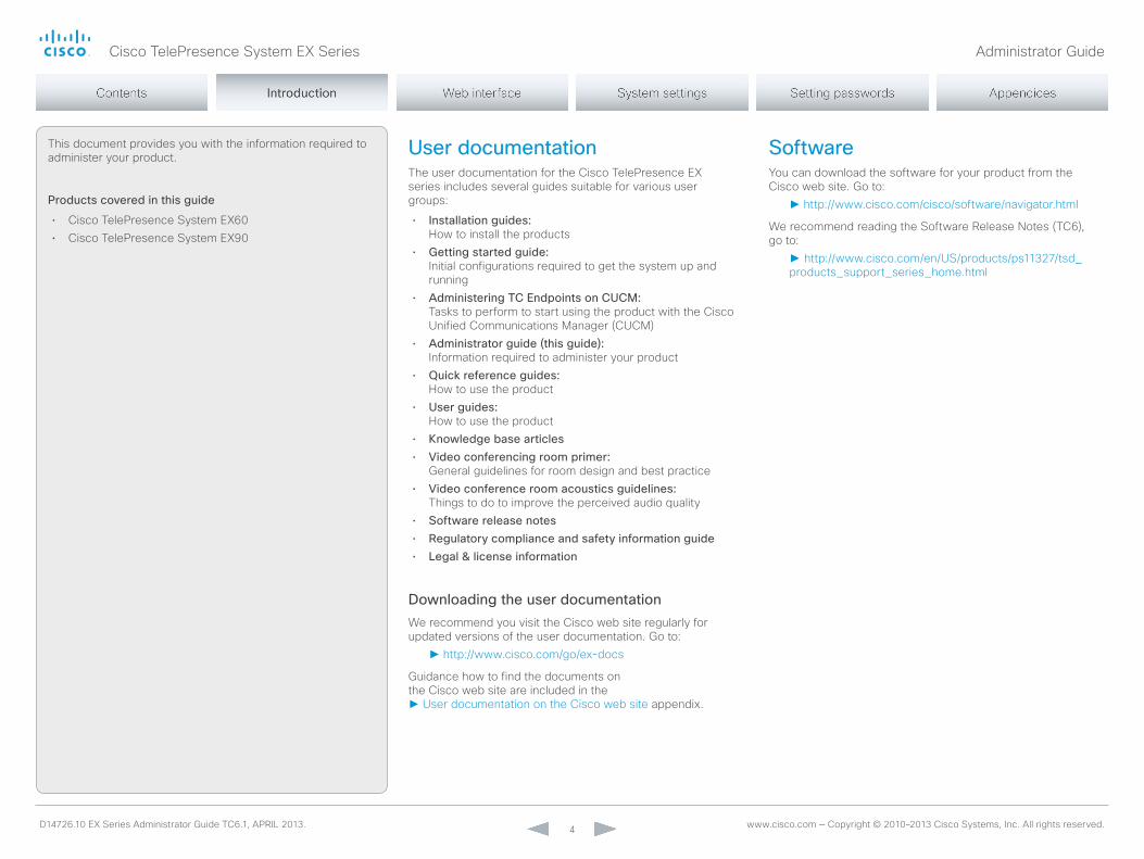
This document provides you with the information required to administer your product.
Products covered in this guide
• Cisco TelePresence System EX60• Cisco TelePresence System EX90
User documentationThe user documentation for the Cisco TelePresence EX series includes several guides suitable for various user groups:
• Installation guides: How to install the products
• Getting started guide: Initial configurations required to get the system up and running
• Administering TC Endpoints on CUCM: Tasks to perform to start using the product with the Cisco Unified Communications manager (CUCm)
• Administrator guide (this guide): Information required to administer your product
• Quick reference guides: How to use the product
• User guides: How to use the product
• Knowledge base articles• Video conferencing room primer:
General guidelines for room design and best practice• Video conference room acoustics guidelines:
Things to do to improve the perceived audio quality• Software release notes• Regulatory compliance and safety information guide• Legal & license information
Downloading the user documentationWe recommend you visit the Cisco web site regularly for updated versions of the user documentation. Go to:
► http://www.cisco.com/go/ex-docs
Guidance how to find the documents on the Cisco web site are included in the ► User documentation on the Cisco web site appendix.
Softwareyou can download the software for your product from the Cisco web site. Go to:
► http://www.cisco.com/cisco/software/navigator.html
We recommend reading the Software Release notes (TC6), go to:
► http://www.cisco.com/en/US/products/ps11327/tsd_products_support_series_home.html

Cisco TelePresence System EX Series Administrator Guide
D14726.10 EX Series Administrator Guide TC6.1, APRIL 2013. www.cisco.com — Copyright © 2010–2013 Cisco Systems, Inc. All rights reserved. 5
New features and improvements
Changes in release key policy and software upgrade management
As from software version TC6.1, you do not need to install new release keys; it is sufficient that the video system has a valid release key for an earlier TC software version.
As from TC6.1 software will be available for download only at ► http://www.cisco.com, and only for users with a valid service contract assigned to a CCo (Cisco online connection) ID.
Password always prompted on Telnet and SSH
When signing into the video system using Telnet or SSH, the password will always be prompted. This applies even when the password is empty (not set).
Diagnostics logging
you can use the Touch controller to enable diagnostics logging of the video system. Diagnostics logging is meant for troubleshooting only, and may lower the system performance while switched on.
G.729 audio codec support in SIP calls
Support for the G.729AB audio codec is added in SIP calls in order to provide better IP phone interoperability. G.729 is not supported in H.323 calls.
Voice mail support and message waiting indication
Endpoints registered to a Cisco Unified Communications manager (CUCm) can be assigned a voice mail profile. When receiving a Busy or No Answer signal from such an endpoint, the call is forwarded to voice mail.
you can access the voice mail from the Touch controller by tapping the messages icon. Also a message waiting notification will appear.
Shared lines support in CUCM
When registered to a Cisco Unified Communications manager (CUCm) the endpoint may be part of a shared line. This means that several devices in the same partition share the same directory number. The different devices sharing the same number receive status from the other appearances on the line.
For example, you can set up a shared line so that many devices share the same number and the first available operator picks up the call (help desk). Assisted call handling, where an administrator manages the calls for an executive (forward, barge in) is another example. Also multiple devices belonging to one person can share the same line, thus allowing him/her to pick up a call on one device and resume it on another (single number reach).
you can find information about how to set up shared lines in the CUCm user documentation (Cisco Unified Communications manager System Guide).
Ad-hoc conferencing in CUCM
Endpoints registered on Cisco Unified Communications manager (CUCm) version 8.6.2 or later can invoke an ad-hoc conference. This requires that a conference bridge is added as an mCU on CUCm. Any endpoint can participate in the conference, regardless of where they are registered.
If the number of participants drops to two, the conference will de-escalate to a point to point call.
What’s new in this versionThis section provides an overview of the new features in the TC6.1 software version.
Software release notesFor a complete overview of the news and changes, we recommend reading the Software Release notes (TC6). Go to:
► http://www.cisco.com/en/US/products/ps11327/tsd_products_support_series_home.html
Software downloadFor software download go to:
► http://www.cisco.com/cisco/software/navigator.html

Cisco TelePresence System EX Series Administrator Guide
D14726.10 EX Series Administrator Guide TC6.1, APRIL 2013. www.cisco.com — Copyright © 2010–2013 Cisco Systems, Inc. All rights reserved. 6
Support for call forwarding (Call Forward All)
When registered to a Cisco Unified Communications manager (CUCm) call forwarding is supported. Call forwarding diverts calls to a specified number. When Call Forward All is activated, all incoming calls are diverted.
The target destination for diverted calls can be set from the Touch controller, or provisioned by CUCm.
you can find information about call forwarding in the CUCm user documentation (Cisco Unified Communications manager System Guide).
Support for consultative transfer
Consultative transfer is supported. A consultative transfer is one in which the transferring party speaks with the third party before connecting the caller to the third party.
Audio-driven microphone mute indication
When in a call, you will be notified if you start speaking while your microphone is muted. The notification - Your microphone is muted - will be displayed on the main display.
Bluetooth headset support
The Bluetooth version 2.1 headset profile is supported. The following functions are included: answer, volume up, volume down and hang up. A Bluetooth headset icon appears in the audio selector on the Touch controller when a headset is paired with the video system. only one headset can be paired at a time.
CTI/JTAPI support (remote expert solution support)
A Cisco Unified Communications manager (CUCm) exposes call control of endpoints via a Java Telephony API (JTAPI). Cisco’s JTAPI enables custom applications to monitor device availability and control calls remotely. The following features are supported: call, answer, disconnect, hold, resume, blind transfer, consultative transfer and consultative conference.
Endpoints registered to a Cisco Unified Communications
manager (CUCm) 9.0 or later support the Cisco Remote Expert Smart Solution (version 1.8).
Refined Touch user interface
• missed calls and message waiting indicators; direct access to voice mail
• new dial pad, soft keyboard and improved text selector• Encryption indicator• Call duration indicator• Possibility to enter a release key if a valid release key is
missing
System configuration changes
New settings
network DHCP RequestTFTPServerAddress
SIP Profile Line
SIP Profile mailbox
Video CamCtrlPip CallSetup mode
Video CamCtrlPip CallSetup Duration
Video SelfviewControl AutoResizing
Settings that are modified
Conference multipoint modeoLD: <Auto/off/multiSite/multiWay>nEW: <Auto/off/multiSite/multiWay/CUCmmediaResourceGroup>

Cisco TelePresence System EX Series Administrator Guide
D14726.10 EX Series Administrator Guide TC6.1, APRIL 2013. www.cisco.com — Copyright © 2010–2013 Cisco Systems, Inc. All rights reserved. 7
EX90 system overviewThe system is delivered with:
• EX90 unit• Touch controller with cable• Handset with cable• DVI-D to DVI-I cable
(recommended for optimal PC image quality)• VGA to DVI-I cable• Stereo audio cable 3.5 mm• Ethernet cable• AC adapter and power cable
EX90, rear view (without rear cover)
Detach the rear side cover when connecting cables.
When finished, snap on the rear cover.
The camera can be tilted and used as a document camera.
EX90, front view
Touch controller
A handset can be attached to the Touch controller.

Cisco TelePresence System EX Series Administrator Guide
D14726.10 EX Series Administrator Guide TC6.1, APRIL 2013. www.cisco.com — Copyright © 2010–2013 Cisco Systems, Inc. All rights reserved. 8
EX60, rear view (without rear cover)
Detach the rear side cover when connecting cables.
When finished, snap on the rear cover.
The camera can be tilted and used as a document camera.
EX60, front view
Touch controller
A handset can be attached to the Touch controller.
EX60 system overviewThe system is delivered with:
• EX60 unit• Touch controller with cable• Handset with cable• DVI-D to DVI-I cable
(recommended for optimal PC image quality)• VGA to DVI-I cable• Stereo audio cable 3.5 mm• Ethernet cable• AC adapter and power cable

Cisco TelePresence System EX Series Administrator Guide
D14726.10 EX Series Administrator Guide TC6.1, APRIL 2013. www.cisco.com — Copyright © 2010–2013 Cisco Systems, Inc. All rights reserved. 9
How to use the Touch controllerThe principal operating device for your Cisco TelePresence EX90 or EX60 system is a Touch controller.
The basic function of the Touch controller is illustrated below.
The Touch controller and its use are described in full detail in the User Guide for your video system.
Basic operating principles
Tap the touch screen to wake up the system, if needed.
Tap a button to activate its function.
Scroll in lists as shown.
mute your microphone
Change the volume
Choose headset, handset or speaker
Use the dial pad for numeric dialing
missed calls indicator
See the list of scheduled meetings
Call Help desk (optional)
Activate Do not disturb mode
open the Settings menu
Use the directory, favorites list or call history list to call someone
Self view
your contact information
Standby
Camera control
Access your voice mail

Cisco TelePresence System EX Series Administrator Guide
D14726.10 EX Series Administrator Guide TC6.1, APRIL 2013. www.cisco.com — Copyright © 2010–2013 Cisco Systems, Inc. All rights reserved. 10
CHAPTER 2
using the web interfAceThe Cisco TelePresence System EX90/EX60 can be configured using the Touch controller or the web interface.
For full access to the system settings, the web interface must be used — the Touch controller provides access to a limited set of parameters only.
The Touch controller and its use are described in the EX90 and EX60 User Guides; the web interface is described in this guide.

Cisco TelePresence System EX Series Administrator Guide
D14726.10 EX Series Administrator Guide TC6.1, APRIL 2013. www.cisco.com — Copyright © 2010–2013 Cisco Systems, Inc. All rights reserved. 11
1. Connect to the video system
open a web browser and enter the IP address of the video system in the address bar.
To find the IP address (IPv4 or IPv6), tap Settings ( ) on the Touch controller.
2. Sign in
Enter the user name and password for your video system and click Sign In.
The system is delivered with a default user named admin with no password (i.e. leave the Password field blank when signing in for the first time).
We strongly recommend that you set a password for the admin user, see the next page.
Signing out
Hover the mouse over your user
name and choose Sign out from the
drop-down list.
Starting the web interfaceThe web interface provides full configuration access to your video conference system.
you can connect from a computer and administer the system remotely.
In this chapter you will find information how to use the web interface for system configuration and maintenance.
We recommend that you use the latest release of one of the major web browser.

Cisco TelePresence System EX Series Administrator Guide
D14726.10 EX Series Administrator Guide TC6.1, APRIL 2013. www.cisco.com — Copyright © 2010–2013 Cisco Systems, Inc. All rights reserved. 12
Changing the system password
We strongly recommend that you set a password for any user with ADmIn rights, including the default admin user, to restrict access to system configuration.
you can read more about password protection in the ► Setting passwords chapter.
1. Open the Change Password dialog
Hover the mouse over your user name, and choose Change password in the drop-down list.
2. Set the new password
Enter your current and new passwords as requested, and click Change password for the change to take effect.
If the password currently is not set, leave the Current password field blank.
Cisco TelePresence System EX Series Administrator Guide
D14726.10 EX Series Administrator Guide TC6.1, APRIL 2013. www.cisco.com — Copyright © 2010–2013 Cisco Systems, Inc. All rights reserved. 13
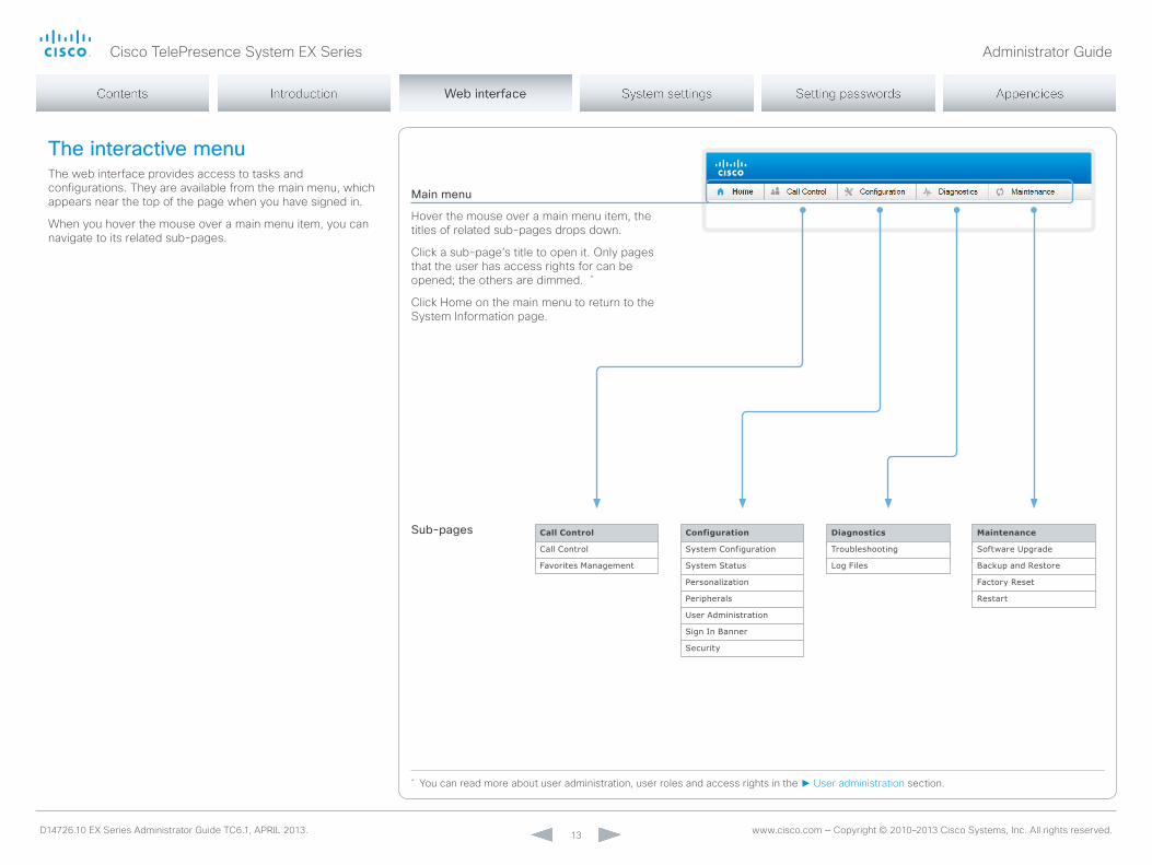
The interactive menuThe web interface provides access to tasks and configurations. They are available from the main menu, which appears near the top of the page when you have signed in.
When you hover the mouse over a main menu item, you can navigate to its related sub-pages.
Main menu
Hover the mouse over a main menu item, the titles of related sub-pages drops down.
Click a sub-page’s title to open it. only pages that the user has access rights for can be opened; the others are dimmed. *
Click Home on the main menu to return to the System Information page.
Call Control
Call Control
Favorites Management
Maintenance
Software Upgrade
Backup and Restore
Factory Reset
Restart
Diagnostics
Troubleshooting
Log Files
Configuration
System Configuration
System Status
Personalization
Peripherals
User Administration
Sign In Banner
Security
Sub-pages
* you can read more about user administration, user roles and access rights in the ► User administration section.
Cisco TelePresence System EX Series Administrator Guide
D14726.10 EX Series Administrator Guide TC6.1, APRIL 2013. www.cisco.com — Copyright © 2010–2013 Cisco Systems, Inc. All rights reserved. 14
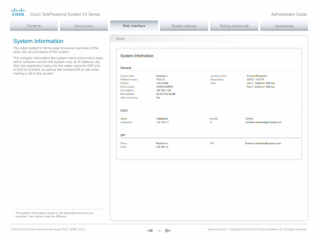
System informationThe video system’s Home page shows an overview of the basic set-up and status of the system.
This includes information like system name and product type, which software version the system runs, its IP address, etc. Also the registration status for the video networks (SIP and H.323) is included, as well as the number/URI to use when making a call to the system.
Home
* The system information shown in the illustration serve as an example. your system may be different.
Cisco TelePresence System EX Series Administrator Guide
D14726.10 EX Series Administrator Guide TC6.1, APRIL 2013. www.cisco.com — Copyright © 2010–2013 Cisco Systems, Inc. All rights reserved. 15
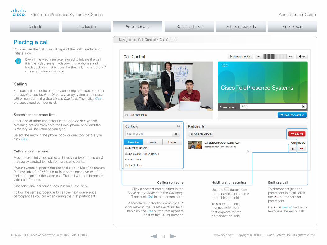
navigate to: Call Control > Call ControlPlacing a callyou can use the Call Control page of the web interface to initiate a call.
Even if the web interface is used to initiate the call it is the video system (display, microphones and loudspeakers) that is used for the call; it is not the PC running the web interface.
Callingyou can call someone either by choosing a contact name in the Local phone book or Directory, or by typing a complete URI or number in the Search and Dial field. Then click Call in the associated contact card.
Searching the contact lists
Enter one or more characters in the Search or Dial field. matching entries from both the Local phone book and the Directory will be listed as you type.
Select the entry in the phone book or directory before you click Call.
Calling more than one
A point-to-point video call (a call involving two parties only) may be expanded to include more participants.
If your system supports the optional built-in multiSite feature (not available for EX60), up to four participants, yourself included, can join the video call. The call will then become a video conference.
one additional participant can join on audio-only.
Follow the same procedure to call the next conference participant as you did when calling the first participant.
Calling someone
Click a contact name, either in the Local phone book or in the Directory.
Then click Call in the contact card.
Alternatively, enter the complete URI or number in the Search and Dial field. Then click the Call button that appears
next to the URI or number.
Ending a call
To disconnect just one participant in a call, click the button for that participant.
Click the End all button to terminate the entire call.
Holding and resuming
Use the button next to the participant’s name to put him on hold.
To resume the call, use the button that appears for the participant on hold.

Cisco TelePresence System EX Series Administrator Guide
D14726.10 EX Series Administrator Guide TC6.1, APRIL 2013. www.cisco.com — Copyright © 2010–2013 Cisco Systems, Inc. All rights reserved. 16
navigate to: Call Control > Call ControlSharing contentyou can connect a presentation source to one of the external inputs of your video system. most often a PC is used as presentation source, but other options may be available depending on your system setup.
While in a call you can share content with the far end, that is the other participant(s) in the call.
If you are not in a call, the content is shared locally on your display.
Sharing content
1. Choose a Presentation source from the drop-down list.
2. Click Start Presentation.
Stop content sharing: Click the Stop Presentation button that becomes visible while sharing.
Cisco TelePresence System EX Series Administrator Guide
D14726.10 EX Series Administrator Guide TC6.1, APRIL 2013. www.cisco.com — Copyright © 2010–2013 Cisco Systems, Inc. All rights reserved. 17
Controlling and monitoring a callyou can control and monitor several call features using the Call Control page.
Audio output selector
Volume down
navigate to: Call Control > Call Control
Call details
If necessary, scroll your browser to
see the call details.
Show/hide call details
Choose between speaker, headset
and handset.
Volume up
Microphone mute
Click the arrow to show details about the call.
Click the arrow again to hide the
information.
Click the button to mute the microphone. Then the text changes to Microphone: Off.
Click again to unmute.

Cisco TelePresence System EX Series Administrator Guide
D14726.10 EX Series Administrator Guide TC6.1, APRIL 2013. www.cisco.com — Copyright © 2010–2013 Cisco Systems, Inc. All rights reserved. 18
navigate to: Call Control > Call ControlLocal layout controlyou can choose a local layout using the Call Control page.
The term layout is used to describe the various ways the videos from the conference participants and a presentation can appear on your screen. Different types of meetings will require different layouts.
Change the layout
1. Click Change Layout.
2. Choose your preferred layout in the window that opens.
you may change the layout while in a call.
Cisco TelePresence System EX Series Administrator Guide
D14726.10 EX Series Administrator Guide TC6.1, APRIL 2013. www.cisco.com — Copyright © 2010–2013 Cisco Systems, Inc. All rights reserved. 19
navigate to: Call Control > Call Control
Snapshots from your video system
Far end snapshots
Capturing snapshotsThe snapshot feature, which is disabled by default, allows snapshots captured by your video system to be displayed on the Call Control page. Captures from your video system’s camera as well as from its presentation channel will be displayed.
This feature might come in handy when administering the video system from a remote location, e.g. to check the camera view.
To use web snapshots you have to sign in with ADmIn credentials.
Enabling the snapshot featureThe snapshot feature is disabled by default. The feature must be enabled using the Touch controller.
• Tap Settings ( ) > Administrator Settings > Web Snapshots and choose On.
Far end snapshots while in a callWhile in a call, snapshots of the remote participant’s main camera and presentation channel (far end) will be captured and displayed as shown in the illustration. The snapshots are updated approximately every 20 seconds.
Far end snapshots are captured even if web snapshots are disallowed on the far end video system. Web snapshots are prohibited only for encrypted calls.
Take live snapshots
While the Live snapshots box is checked, snapshots are captured by your video system (main camera and presentation) approximately every two
seconds.

Cisco TelePresence System EX Series Administrator Guide
D14726.10 EX Series Administrator Guide TC6.1, APRIL 2013. www.cisco.com — Copyright © 2010–2013 Cisco Systems, Inc. All rights reserved. 20
navigate to: Call Control > Favorites managementManaging the favorites listThe entries in the favorites list can be accessed from the Touch controller and the Web interface.
Adding a contact
Click Add contact and fill in the form that pops up. Then
click Save to store the contact in the favorites list.
Editing contact details
Click a contacts name followed by Edit. Change the details in the form as
appropriate and click Save.
Deleting a contact
Click a contacts name followed by Edit. Then click Delete to remove the entry
from the favorites list.
Adding a contact method
you can store more than one contact method for each contact, e.g. video, telephone and mobile.
Storing a contact in a folder
Choose the appropriate folder from the drop down list.
no folder means that the contact will be stored at the top level.
Cisco TelePresence System EX Series Administrator Guide
D14726.10 EX Series Administrator Guide TC6.1, APRIL 2013. www.cisco.com — Copyright © 2010–2013 Cisco Systems, Inc. All rights reserved. 21
navigate to: Call Control > Favorites managementFavorite list foldersThe entries in the favorites list can be organized in folders.
Editing folders
i. Click Edit folders. ii. Click the name of an existing
folder to view and edit its details; or click Add folder and fill in its details to create at new folder.
iii. Click Save folder to store the details; or click Delete folder
to remove the folder and all its contacts and sub-folders.
Opening a folder
Click the folder name to open the folder and show its list of contacts.

Cisco TelePresence System EX Series Administrator Guide
D14726.10 EX Series Administrator Guide TC6.1, APRIL 2013. www.cisco.com — Copyright © 2010–2013 Cisco Systems, Inc. All rights reserved. 22
navigate to: Configuration > System Configuration
Selecting a category
The system settings are structured in several categories. Choose a category to display the related settings.
System configurationThe system settings are grouped in several categories. When you choose a category in the left pane all related settings appear to the right.
Each system setting is further described in the ► System settings chapter.
Expanding and collapsing lists
Use the buttons to expand and collapse all or individual lists.
Searching for settings
Enter as many letters as needed in the search field. All settings containing these letters will be highlighted.
* The configuration shown in the illustration serve as an example. your system may be configured differently.

Cisco TelePresence System EX Series Administrator Guide
D14726.10 EX Series Administrator Guide TC6.1, APRIL 2013. www.cisco.com — Copyright © 2010–2013 Cisco Systems, Inc. All rights reserved. 23
navigate to: Configuration > System ConfigurationChanging system settingsAll system settings can be changed from the System Configuration page. The value space for a setting is specified either as a drop-down list or with explanatory text following a text input field.
Different settings may require different user credentials. In order to be sure that an administrator is able to change all system settings, the user must possess all user roles.
you can read more about user administration and user roles in the ► User administration chapter.
Drop-down list
Click the arrow to open the drop-down list. Choose the preferred value and click Save for the change to take effect.
Text input field
Enter text in the input field and click Save for the change to take effect.

Cisco TelePresence System EX Series Administrator Guide
D14726.10 EX Series Administrator Guide TC6.1, APRIL 2013. www.cisco.com — Copyright © 2010–2013 Cisco Systems, Inc. All rights reserved. 24
navigate to: Configuration > System ConfigurationSetting the Administrator Settings menu passwordWhen starting up the video conference system for the first time anyone can access the Administrator Settings menu with the Touch controller because the menu password is not set.
We strongly recommend that you define a menu password, because the Administrator Settings may severely affect the behavior of the video conference system.
you can read more about password protection in the ► Setting passwords chapter.
Changing the menu password
Click Set/Change Administrator Settings menu password to open this dialog.
Enter a new password in the text input field and click Save to store it.
Use the Unlock button to clear the existing password.
Cisco TelePresence System EX Series Administrator Guide
D14726.10 EX Series Administrator Guide TC6.1, APRIL 2013. www.cisco.com — Copyright © 2010–2013 Cisco Systems, Inc. All rights reserved. 25
navigate to: Configuration > System Status
Selecting a category
The system status is structured in several categories. Choose a category
to display the related status information.
Expanding and collapsing lists
Use the buttons to expand and collapse all or individual lists.
Searching for status entries
Enter as many letters as needed in the search field. All entries containing these letters will be highlighted.
System statusThe system status is grouped in several categories. When you choose a category in the left column, the related status appears in the window to the right.*
* The status shown in the illustration serve as an example. The status of your system may be different.

Cisco TelePresence System EX Series Administrator Guide
D14726.10 EX Series Administrator Guide TC6.1, APRIL 2013. www.cisco.com — Copyright © 2010–2013 Cisco Systems, Inc. All rights reserved. 26
navigate to: Configuration > Personalization : Wallpaper tabChoosing a wallpaperyou can choose from a set of predefined wallpapers to use as background on your display.
If you want the company logo or another custom picture to be displayed on the main display, you may upload and use a custom wallpaper.
The custom wallpaper applies to only the main display and will not appear on the Touch controller.
Choosing a wallpaper
Choose a wallpaper from the list.
If you have uploaded a custom wallpaper, it will appear in the list together with the predefined wallpapers.
The chosen wallpaper is highlighted.
Uploading a custom wallpaper file
Click Browse... and locate your custom wallpaper image file.
The file format must be .png and the maximum image size is 1920 × 1200 pixels.
Click Upload to save the file to the video system.
Cisco TelePresence System EX Series Administrator Guide
D14726.10 EX Series Administrator Guide TC6.1, APRIL 2013. www.cisco.com — Copyright © 2010–2013 Cisco Systems, Inc. All rights reserved. 27
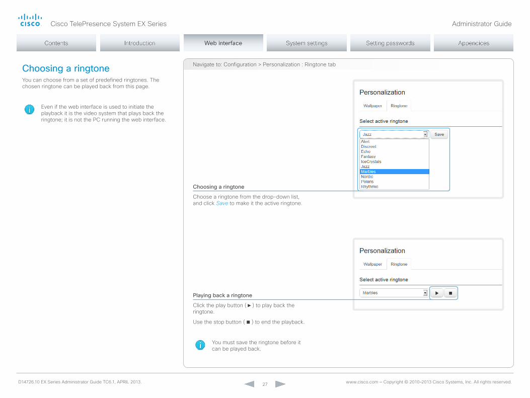
navigate to: Configuration > Personalization : Ringtone tabChoosing a ringtoneyou can choose from a set of predefined ringtones. The chosen ringtone can be played back from this page.
Even if the web interface is used to initiate the playback it is the video system that plays back the ringtone; it is not the PC running the web interface.
Choosing a ringtone
Choose a ringtone from the drop-down list, and click Save to make it the active ringtone.
Playing back a ringtone
Click the play button ( ► ) to play back the ringtone.
Use the stop button ( ) to end the playback.
you must save the ringtone before it can be played back.
Cisco TelePresence System EX Series Administrator Guide
D14726.10 EX Series Administrator Guide TC6.1, APRIL 2013. www.cisco.com — Copyright © 2010–2013 Cisco Systems, Inc. All rights reserved. 28
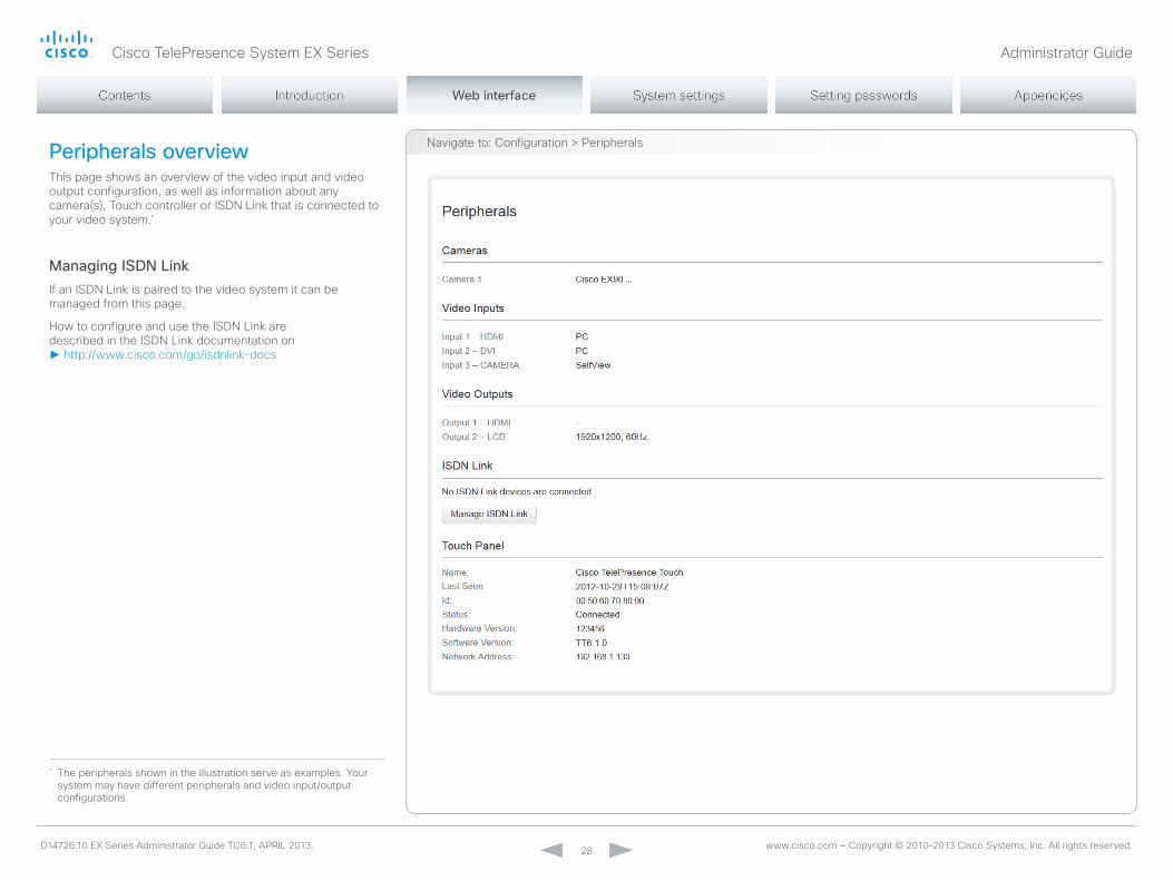
navigate to: Configuration > PeripheralsPeripherals overviewThis page shows an overview of the video input and video output configuration, as well as information about any camera(s), Touch controller or ISDn Link that is connected to your video system.*
Managing ISDN LinkIf an ISDn Link is paired to the video system it can be managed from this page.
How to configure and use the ISDn Link are described in the ISDn Link documentation on ► http://www.cisco.com/go/isdnlink-docs
* The peripherals shown in the illustration serve as examples. your system may have different peripherals and video input/output configurations.

Cisco TelePresence System EX Series Administrator Guide
D14726.10 EX Series Administrator Guide TC6.1, APRIL 2013. www.cisco.com — Copyright © 2010–2013 Cisco Systems, Inc. All rights reserved. 29
User administrationFrom this page you can manage the user accounts of your video conference system. you can create new user accounts, edit the details of existing users, and delete users.
The default user accountThe system comes with a default administrator user account with full access rights. The username is admin and no password is set.
It is highly recommended to set a password for the admin user.
Read more about passwords in the ► Setting passwords chapter.
About user rolesA user account must hold one or a combination of several user roles.
The following three user roles, with non-overlapping rights, exist:
• ADmIn: A user holding this role can create new users and change most settings. The user neither can upload audit certificates nor change the security audit settings.
• USER: A user holding this role can make calls and search the phone book. The user can modify a few settings, e.g. adjusting the audio volume and changing the menu language.
• AUDIT: A user holding this role can change the security audit configurations and upload audit certificates.
An administrator user account with full access rights, like the default admin user, must possess all the three roles.
Default user account
The system comes with admin as the default user account. This user has full access rights.
navigate to: Configuration > User Administration

Cisco TelePresence System EX Series Administrator Guide
D14726.10 EX Series Administrator Guide TC6.1, APRIL 2013. www.cisco.com — Copyright © 2010–2013 Cisco Systems, Inc. All rights reserved. 30
User administration, continued
Creating a new user accountFollow these steps in order to create a new user account:
1. Click Add new user....
2. Fill in the Username, Password and PIn code*, and check the appropriate user roles check boxes.
As a default the user has to change the password and PIn code when signing in for the first time.
Do not fill in the Distinguished name (Dn) Subject field unless you want to use certificate login on https.
3. Set the Status to Active to activate the user.
4. Click Create User to save the changes.
Use the Back button to leave without making any changes.
navigate to: Configuration > User Administration
* The password is used with the web interface and command line interface. The PIn code is used with the on-screen menu.

Cisco TelePresence System EX Series Administrator Guide
D14726.10 EX Series Administrator Guide TC6.1, APRIL 2013. www.cisco.com — Copyright © 2010–2013 Cisco Systems, Inc. All rights reserved. 31
User administration, continued
Changing user privilegesFollow these steps in order to change the user privileges:
1. Click the name of an existing user to open the Editing user window.
2. Check the appropriate user roles check boxes, decide if the user has to change the password and PIn code on the next sign in, and fill in the Distinguished name (Dn) Subject field if using certificate login on https.
3. Click Update User to save the changes.
Use the Back button to leave without making any changes.
Changing the password or PIN codeFollow these steps in order to change the password or PIn code:
1. Click the name of an existing user to open the Editing user window.
2. Enter the new password or PIn code in the appropriate input fields.
3. Click Change Password or Change PIN to save the change.
Use the Back button to leave without making any changes.
navigate to: Configuration > User Administration

Cisco TelePresence System EX Series Administrator Guide
D14726.10 EX Series Administrator Guide TC6.1, APRIL 2013. www.cisco.com — Copyright © 2010–2013 Cisco Systems, Inc. All rights reserved. 32
User administration, continued
Deactivating a user accountFollow these steps in order to deactivate a user account:
Always keep at least one user with ADmIn rights Active.
1. Click the name of an existing user to open the Editing user window.
2. Set the Status to Inactive.
3. Click Update User to save the changes.
Use the Back button to leave without making any changes.
Deleting a user accountFollow these steps in order to delete a user account:
Always keep at least one user with ADmIn rights.
1. Click the name of an existing user to open the Editing user window.
2. Click Delete user... and confirm when prompted.
navigate to: Configuration > User Administration

Cisco TelePresence System EX Series Administrator Guide
D14726.10 EX Series Administrator Guide TC6.1, APRIL 2013. www.cisco.com — Copyright © 2010–2013 Cisco Systems, Inc. All rights reserved. 33
Adding a sign in bannerA sign in banner is a message that is displayed to the user when signing in.
If a system administrator wants to provide initial information to all users, he can create a sign in banner. The message will be shown when the user signs in to the web interface or the command line interface.
Adding a sign in banner
Enter the message that you want to present to the user
when signing in, and click Save to activate the banner.
navigate to: Configuration > Sign In Banner

Cisco TelePresence System EX Series Administrator Guide
D14726.10 EX Series Administrator Guide TC6.1, APRIL 2013. www.cisco.com — Copyright © 2010–2013 Cisco Systems, Inc. All rights reserved. 34
Managing the video system’s certificatesCertificate validation may be required when using TLS (Transport Layer Security).
A server or client may require that your video system presents a valid certificate to them before communication can be set up.
The video system’s certificates are text files that verify the authenticity of the system. These certificates may be issued by a certificate authority (CA).
The certificate are listed as shown in the illustration to the right *. They can be used for the following services: HTTPS, SIP and IEEE 802.1X.
you can store several certificates on the system, but only one certificate can be used for each service at a time.
If authentication fails, the connection will not be established.Enabling and disabling certificates
Use the buttons to switch a certificate on or off for the different services.
you can also view a certificate, and delete a certificate using the corresponding buttons.
Contact your system administrator to obtain the following file(s):
• Certificate (file format: .PEm)• Private key, may be included in the same file as
the certificate (file format: .PEm format)• Password (required only if the private key is
encrypted)
The certificate and the private key will be stored in the same file on the video system.
Adding a certificate
1. Click Add certificate... to open the certificate dialog.
2. Click Browse... and find the Certificate and Private key file(s) on your computer.
3. Fill in the Password if required.
4. Click the blue Add certificate... button to store the certificate on your system.
navigate to: Configuration > Security
* The certificates and certificate issuers shown in the illustration serve as examples. your system may have other certificate(s).
Cisco TelePresence System EX Series Administrator Guide
D14726.10 EX Series Administrator Guide TC6.1, APRIL 2013. www.cisco.com — Copyright © 2010–2013 Cisco Systems, Inc. All rights reserved. 35
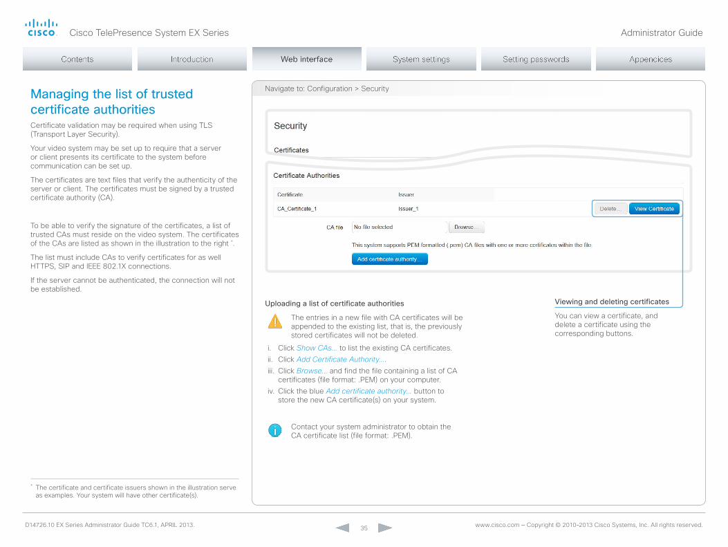
navigate to: Configuration > SecurityManaging the list of trusted certificate authoritiesCertificate validation may be required when using TLS (Transport Layer Security).
your video system may be set up to require that a server or client presents its certificate to the system before communication can be set up.
The certificates are text files that verify the authenticity of the server or client. The certificates must be signed by a trusted certificate authority (CA).
To be able to verify the signature of the certificates, a list of trusted CAs must reside on the video system. The certificates of the CAs are listed as shown in the illustration to the right *.
The list must include CAs to verify certificates for as well HTTPS, SIP and IEEE 802.1X connections.
If the server cannot be authenticated, the connection will not be established.
* The certificate and certificate issuers shown in the illustration serve as examples. your system will have other certificate(s).
Uploading a list of certificate authorities
The entries in a new file with CA certificates will be appended to the existing list, that is, the previously stored certificates will not be deleted.
i. Click Show CAs... to list the existing CA certificates.ii. Click Add Certificate Authority....iii. Click Browse... and find the file containing a list of CA
certificates (file format: .PEm) on your computer.iv. Click the blue Add certificate authority... button to
store the new CA certificate(s) on your system.
Contact your system administrator to obtain the CA certificate list (file format: .PEm).
Viewing and deleting certificates
you can view a certificate, and delete a certificate using the corresponding buttons.
Cisco TelePresence System EX Series Administrator Guide
D14726.10 EX Series Administrator Guide TC6.1, APRIL 2013. www.cisco.com — Copyright © 2010–2013 Cisco Systems, Inc. All rights reserved. 36
navigate to: Configuration > Security / Configuration > System Configuration
i
ii
iii
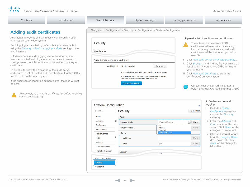
Adding audit certificatesAudit logging records all sign in activity and configuration changes on your video system.
Audit logging is disabled by default, but you can enable it using the Security > Audit > Logging > Mode setting on the web interface.
In ExternalSecure audit logging mode the video system sends encrypted audit logs to an external audit server (syslog server), which identity must be verified by a signed certificate.
To be able to verify the signature of the audit server certificates, a list of trusted audit certificate authorities (CAs) must reside on the video system.
If the audit server cannot be authenticated, the logs will not be sent.
Always upload the audit certificate list before enabling secure audit logging.
1. Upload a list of audit server certificates
The entries in a new file with CA certificates will overwrite the existing list, that is, any previously stored audit certificates will be lost when you add a new file.
i. Click Add audit server certificate authority....ii. Click Browse... and find the file containing the
list of audit CA certificates (.PEm format) on your computer.
iii. Click Add audit certificate to store the certificate(s) on your system.
Contact your system administrator to obtain the Audit CA list (file format: .PEm).
2. Enable secure audit loggingi. Go to the System
Configuration page and choose the Security category.
ii. Enter the Address and Port number of the audit server. Click Save for the changes to take effect.
iii. Choose ExternalSecure from the Logging Mode drop-down list. Click Save for the change to take effect.

Cisco TelePresence System EX Series Administrator Guide
D14726.10 EX Series Administrator Guide TC6.1, APRIL 2013. www.cisco.com — Copyright © 2010–2013 Cisco Systems, Inc. All rights reserved. 37
navigate to: Configuration > SecuritySetting strong security modeStrong security mode should be used only when compliance with DoD JITC regulations is required.
Read the warning carefully before setting strong security mode.
Strong security mode sets very strict password requirements, and requires all users to change their password on the next sign in.
Software upload from TmS, web snapshots and calling from the web interface are prohibited in strong security mode.
Setting strong security mode
1. Click Configure strong security mode... and read the warning carefully before continuing.
2. If you want to use strong security mode, check the I understand the risks of strong security mode check box and click Enable strong security mode.
3. Change the password to meet the strict criteria shown in the warning. How to change the system password: see the ► Setting passwords section.
4. Restart the codec for the change to take effect.
Return to normal mode
1. When in strong security mode, the system can be restored to normal mode by clicking Configure strong security mode... followed by Disable strong security mode.
2. Restart the codec for the change to take effect.
Cisco TelePresence System EX Series Administrator Guide
D14726.10 EX Series Administrator Guide TC6.1, APRIL 2013. www.cisco.com — Copyright © 2010–2013 Cisco Systems, Inc. All rights reserved. 38
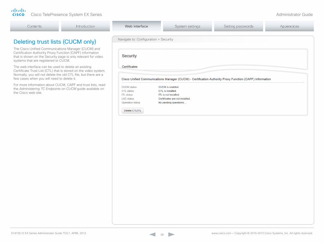
navigate to: Configuration > SecurityDeleting trust lists (CUCM only)The Cisco Unified Communications manager (CUCm) and Certification Authority Proxy Function (CAPF) information that is shown on the Security page is only relevant for video systems that are registered to CUCm.
The web interface can be used to delete an existing Certificate Trust List (CTL) that is stored on the video system. normally, you will not delete the old CTL file, but there are a few cases when you will need to delete it.
For more information about CUCm, CAPF and trust lists, read the Administering TC Endpoints on CUCM guide available on the Cisco web site.
Cisco TelePresence System EX Series Administrator Guide
D14726.10 EX Series Administrator Guide TC6.1, APRIL 2013. www.cisco.com — Copyright © 2010–2013 Cisco Systems, Inc. All rights reserved. 39
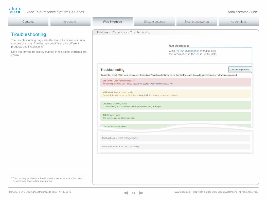
navigate to: Diagnostics > TroubleshootingTroubleshootingThe troubleshooting page lists the status for some common sources of errors. The list may be different for different products and installations.*
note that errors are clearly marked in red color; warnings are yellow.
Run diagnostics
Click Re-run diagnostics to make sure the information in the list is up-to-date.
* The messages shown in the illustration serve as examples. your system may show other information.

Cisco TelePresence System EX Series Administrator Guide
D14726.10 EX Series Administrator Guide TC6.1, APRIL 2013. www.cisco.com — Copyright © 2010–2013 Cisco Systems, Inc. All rights reserved. 40
navigate to: Diagnostics > Log FilesDownloading log filesThe log files* are Cisco specific debug files which may be requested by the Cisco support organization if you need technical support.
The current log files are time stamped event log files.
All current log files are archived in a time stamped historical log file each time the system reboots. If the maximum number of historical log files is reached, the oldest one will be overwritten.
Downloading all files
Click Download log files archive and follow the instructions.
Open a log file
Click the file name to open the log file in the web browser.
* The log files shown in the illustration serve as examples. your system may have other files.

Cisco TelePresence System EX Series Administrator Guide
D14726.10 EX Series Administrator Guide TC6.1, APRIL 2013. www.cisco.com — Copyright © 2010–2013 Cisco Systems, Inc. All rights reserved. 41
Upgrading the system softwareThis video conference system is using TC software. The version described in this document is TC6.1.
Contact your system administrator if you have questions about the software version.
Software release notes
For a complete overview of the news and changes, we recommend reading the Software Release notes (TC6).
Go to: ► http://www.cisco.com/en/US/products/ps11327/tsd_products_support_series_home.html
New software
For software download, go to the Cisco Download Software web page: ► http://www.cisco.com/cisco/software/navigator.html. Then navigate to your product.
The file name is something like “s52000tc6_1_0.pkg” (each software version has a unique file name).
Release key and option keys
you need a valid release key to be able to use the TC software. As from version TC6.1, any TC release key will do.
For older releases the release key is specific for each main release (e.g. TC4, TC5, TC6). If you want to downgrade the software to TC6.0 or older, take care to have the correct key.
An option key is required to activate optional functionality. you may have several option keys in your system.
The available options are:
• Premium resolution• multiSite (only EX90)• Dual display (only EX90)
Adding release and option keys
If you already have a valid release key and the proper option keys installed on your system, you can skip this point and continue with the software installation.
If you do not have the required key(s), contact your Cisco representative to obtain them. Then perform the following steps:i. Enter the Release key in the appropriate text input field
and click Add. ii. Enter an Option Key in the appropriate text input field
and click Add.
If you have more than one option key, repeat step ii for all of them.
Each system has unique keys, for example:
• 1TC006-1-0C22E348 (release key)• 1R000-1-AA7A4A09 (option key)
Installing new software
Download the appropriate software package from the Cisco Software Download web page (see link to the left) and store it on your local computer. This is a .pkg file.
i. Click Browse... and find the downloaded .pkg file that contains the new software.
ii. Check the Upgrade automatically after upload check box, then click Upload to start the installation process straight away.
Keep the check box unchecked if you want to upload the software now and do the installation later.
The complete installation may take up to 30 minutes. you can follow the progress on the web page. The system reboots automatically after the installation.
you must sign in anew in order to continue working with the web interface after the reboot.
navigate to: maintenance > Software Upgrade
Release key and option keys
The release key is required to be able to use the software. A new release key is required for every major software release (e.g. when upgrading from TC5.x or older to TC6.x).
Cisco TelePresence System EX Series Administrator Guide
D14726.10 EX Series Administrator Guide TC6.1, APRIL 2013. www.cisco.com — Copyright © 2010–2013 Cisco Systems, Inc. All rights reserved. 42
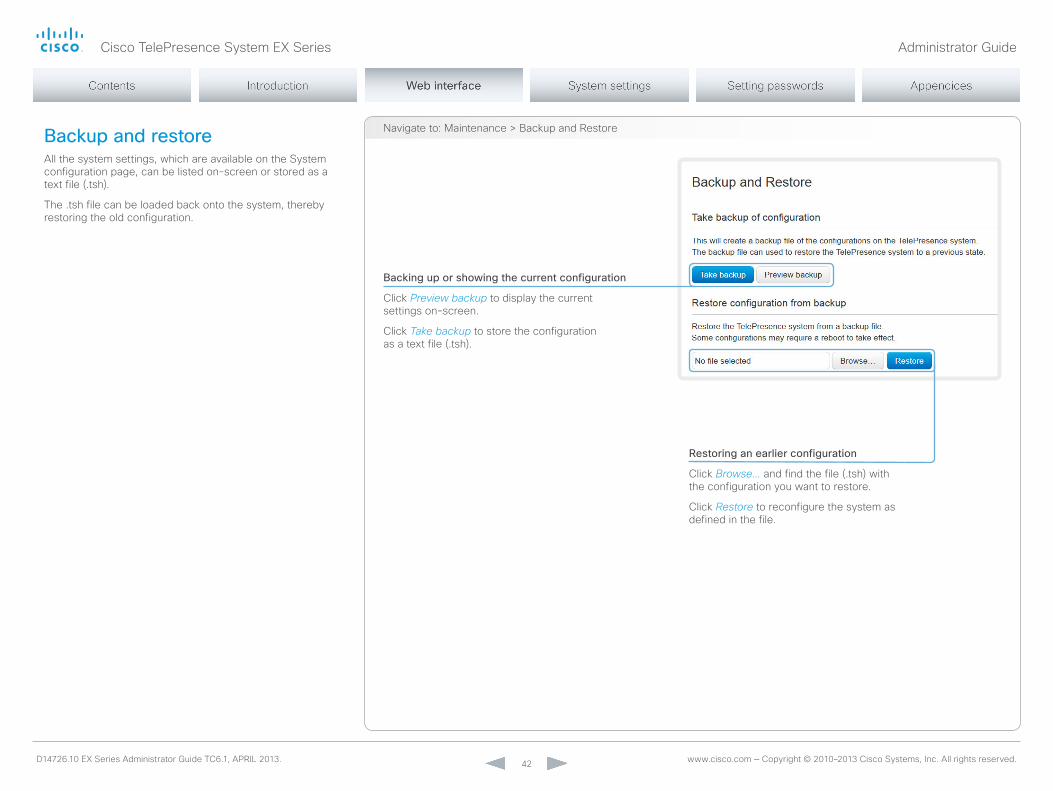
Backup and restoreAll the system settings, which are available on the System configuration page, can be listed on-screen or stored as a text file (.tsh).
The .tsh file can be loaded back onto the system, thereby restoring the old configuration.
Backing up or showing the current configuration
Click Preview backup to display the current settings on-screen.
Click Take backup to store the configuration as a text file (.tsh).
Restoring an earlier configuration
Click Browse... and find the file (.tsh) with the configuration you want to restore.
Click Restore to reconfigure the system as defined in the file.
navigate to: maintenance > Backup and Restore
Cisco TelePresence System EX Series Administrator Guide
D14726.10 EX Series Administrator Guide TC6.1, APRIL 2013. www.cisco.com — Copyright © 2010–2013 Cisco Systems, Inc. All rights reserved. 43
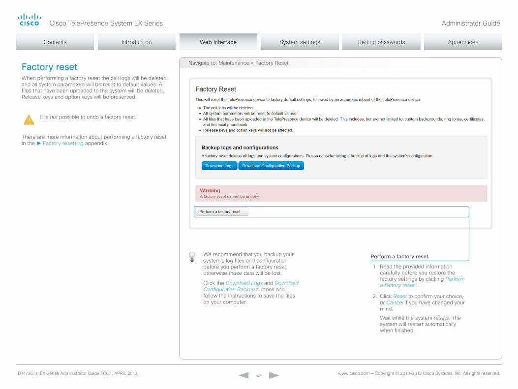
Factory resetWhen performing a factory reset the call logs will be deleted and all system parameters will be reset to default values. All files that have been uploaded to the system will be deleted. Release keys and option keys will be preserved.
It is not possible to undo a factory reset.
There are more information about performing a factory reset in the ► Factory resetting appendix.
Perform a factory reset
1. Read the provided information carefully before you restore the factory settings by clicking Perform a factory reset....
2. Click Reset to confirm your choice, or Cancel if you have changed your mind.
Wait while the system resets. The system will restart automatically when finished.
navigate to: maintenance > Factory Reset
We recommend that you backup your system’s log files and configuration before you perform a factory reset; otherwise these data will be lost.
Click the Download Logs and Download Configuration Backup buttons and follow the instructions to save the files on your computer.

Cisco TelePresence System EX Series Administrator Guide
D14726.10 EX Series Administrator Guide TC6.1, APRIL 2013. www.cisco.com — Copyright © 2010–2013 Cisco Systems, Inc. All rights reserved. 44
Restarting the systemThe system can be shut down or restarted remotely using the web interface.
Restarting the system
Click Restart TelePresence device... to restart the system.
It will take a few minutes before the system is ready for use.
Shutting down the system
Click Shutdown TelePresence device... to shut down the system.
The system cannot be turned on again remotely; you must press its power button physically to turn it on.
navigate to: maintenance > Restart
Cisco TelePresence System EX Series Administrator Guide
D14726.10 EX Series Administrator Guide TC6.1, APRIL 2013. www.cisco.com — Copyright © 2010–2013 Cisco Systems, Inc. All rights reserved. 45
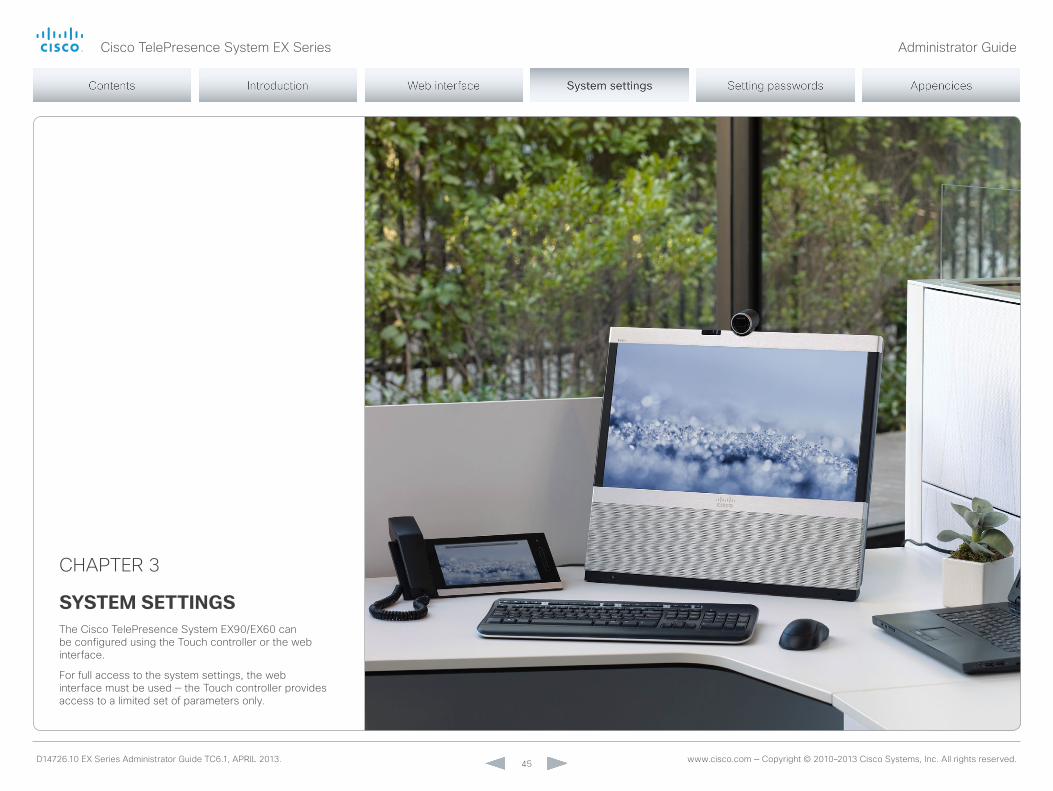
CHAPTER 3
system settingsThe Cisco TelePresence System EX90/EX60 can be configured using the Touch controller or the web interface.
For full access to the system settings, the web interface must be used — the Touch controller provides access to a limited set of parameters only.

Cisco TelePresence System EX Series Administrator Guide
D14726.10 EX Series Administrator Guide TC6.1, APRIL 2013. www.cisco.com — Copyright © 2010–2013 Cisco Systems, Inc. All rights reserved. 46
Overview of the system settingsIn the following pages you will find a complete list of the system settings which are configured from the System Configuration page on the web interface. The examples show either the default value or an example of a value.
open a web browser and enter the IP address of the video system; then sign in.
Tap Settings ( ) > System Information on the Touch controller to find the system's IP address (IPv4 or IPv6).
Audio settings ..................................................................... 49Audio InternalSpeaker mode ................................................. 49Audio microphones mute Enabled ........................................ 49Audio PreferredoutputConnector ......................................... 49Audio SoundsAndAlerts KeyTones mode ............................. 49Audio SoundsAndAlerts RingTone ........................................ 49Audio SoundsAndAlerts RingVolume .................................... 50Audio Volume ........................................................................ 50Audio VolumeHandset........................................................... 50Audio VolumeHeadset .......................................................... 50
Cameras settings .................................................................51Cameras Camera [1..1] Backlight ...........................................51Cameras Camera [1..1] Brightness Level ...............................51Cameras Camera [1..1] Brightness mode ...............................51Cameras Camera [1..1] Focus mode ......................................51Cameras Camera [1..1] FrameRate .........................................51Cameras Camera [1..1] Gamma Level ................................... 52Cameras Camera [1..1] Gamma mode .................................. 52Cameras Camera [1..1] Whitebalance Level .......................... 52Cameras Camera [1..1] Whitebalance mode ......................... 52Cameras PowerLine Frequency .............................................51
Conference settings ........................................................... 53Conference [1..1] AutoAnswer Delay ..................................... 53Conference [1..1] AutoAnswer mode..................................... 53Conference [1..1] AutoAnswer mute ...................................... 53Conference [1..1] DefaultCall Protocol ................................... 54Conference [1..1] DefaultCall Rate ......................................... 54Conference [1..1] DonotDisturb DefaultTimeout.................... 54Conference [1..1] DonotDisturb mode .................................. 53Conference [1..1] Encryption mode ....................................... 54Conference [1..1] FarEndControl mode ................................. 54Conference [1..1] FarEndControl SignalCapability ................. 54Conference [1..1] IncomingmultisiteCall mode ...................... 57Conference [1..1] maxReceiveCallRate ................................. 55Conference [1..1] maxTotalReceiveCallRate .......................... 55Conference [1..1] maxTotalTransmitCallRate ......................... 55Conference [1..1] maxTransmitCallRate ................................. 55Conference [1..1] micUnmuteonDisconnect mode ............... 53Conference [1..1] multipoint mode ........................................ 57Conference [1..1] PacketLossResilience mode ..................... 56Conference [1..1] Presentation onPlacedonHold ................. 56Conference [1..1] Presentation Policy .................................... 56
Conference [1..1] Presentation RelayQuality ......................... 56Conference [1..1] TelephonyPrefix ......................................... 53Conference [1..1] VideoBandwidth mainChannel Weight ...... 55Conference [1..1] VideoBandwidth mode .............................. 55Conference [1..1] VideoBandwidth PresentationChannel Weight ................................................................................... 56
FacilityService settings ....................................................... 58FacilityService Service [1..5] CallType .................................. 58FacilityService Service [1..5] name....................................... 58FacilityService Service [1..5] number ................................... 58FacilityService Service [1..5] Type ........................................ 58
H323 settings ...................................................................... 59H323 nAT Address ............................................................... 59H323 nAT mode ................................................................... 59H323 Profile [1..1] Authentication Loginname ....................... 59H323 Profile [1..1] Authentication mode ................................ 59H323 Profile [1..1] Authentication Password ......................... 60H323 Profile [1..1] CallSetup mode ........................................ 60H323 Profile [1..1] Gatekeeper Address ................................ 60H323 Profile [1..1] Gatekeeper Discovery .............................. 60H323 Profile [1..1] H323Alias E164 ........................................ 60H323 Profile [1..1] H323Alias ID ............................................. 60H323 Profile [1..1] PortAllocation ........................................... 61
Network settings ................................................................. 62network [1..1] Assignment ..................................................... 62network [1..1] DHCP RequestTFTPServerAddress ............... 63network [1..1] DnS Domain name ......................................... 63network [1..1] DnS Server [1..3] Address .............................. 63network [1..1] IEEE8021X AnonymousIdentity ....................... 66network [1..1] IEEE8021X Eap md5 ....................................... 66network [1..1] IEEE8021X Eap Peap ...................................... 67network [1..1] IEEE8021X Eap Tls .......................................... 67network [1..1] IEEE8021X Eap Ttls ......................................... 67network [1..1] IEEE8021X Identity .......................................... 66network [1..1] IEEE8021X mode ............................................ 65network [1..1] IEEE8021X Password ...................................... 66network [1..1] IEEE8021X TlsVerify ........................................ 66network [1..1] IEEE8021X UseClientCertificate ..................... 66network [1..1] IPStack ............................................................ 62network [1..1] IPv4 Address .................................................. 62network [1..1] IPv4 Gateway .................................................. 62

Cisco TelePresence System EX Series Administrator Guide
D14726.10 EX Series Administrator Guide TC6.1, APRIL 2013. www.cisco.com — Copyright © 2010–2013 Cisco Systems, Inc. All rights reserved. 47
network [1..1] IPv4 Subnetmask ............................................ 62network [1..1] IPv6 Address .................................................. 63network [1..1] IPv6 Assignment ............................................. 62network [1..1] IPv6 DHCPoptions ......................................... 63network [1..1] IPv6 Gateway .................................................. 63network [1..1] mTU ................................................................ 67network [1..1] QoS Diffserv Audio ......................................... 64network [1..1] QoS Diffserv Data ........................................... 64network [1..1] QoS Diffserv ICmPv6 ..................................... 65network [1..1] QoS Diffserv nTP ........................................... 65network [1..1] QoS Diffserv Signalling ................................... 65network [1..1] QoS Diffserv Video ......................................... 64network [1..1] QoS mode ...................................................... 64network [1..1] RemoteAccess Allow ...................................... 68network [1..1] Speed ............................................................. 67network [1..1] TrafficControl mode ........................................ 67network [1..1] VLAn Voice mode .......................................... 68network [1..1] VLAn Voice VlanId .......................................... 68
NetworkServices settings ................................................... 69networkServices CTmS Encryption ..................................... 72networkServices CTmS mode ............................................. 72networkServices H323 mode .............................................. 69networkServices HTTP mode .............................................. 69networkServices HTTPS mode ............................................ 69networkServices HTTPS oCSP mode ................................. 70networkServices HTTPS oCSP URL ................................... 70networkServices HTTPS VerifyClientCertificate .................. 70networkServices HTTPS VerifyServerCertificate ................ 70networkServices multiWay Address .................................... 69networkServices multiWay Protocol .................................... 69networkServices nTP Address ............................................ 70networkServices nTP mode ................................................ 70networkServices SIP mode .................................................. 71networkServices SnmP Communityname .......................... 71networkServices SnmP Host [1..3] Address ........................ 71networkServices SnmP mode ............................................. 71networkServices SnmP SystemContact.............................. 71networkServices SnmP SystemLocation ............................ 71networkServices SSH AllowPublicKey ................................. 72networkServices SSH mode ................................................ 72networkServices Telnet mode.............................................. 72networkServices XmLAPI mode .......................................... 69
Phonebook settings ............................................................ 73Phonebook Server [1..1] ID .................................................... 73Phonebook Server [1..1] Type ............................................... 73Phonebook Server [1..1] URL ................................................ 73
Provisioning settings ............................................................74Provisioning Connectivity.......................................................74Provisioning Externalmanager Address ................................ 75Provisioning Externalmanager Domain ................................. 75Provisioning Externalmanager Path ...................................... 75Provisioning Externalmanager Protocol ................................ 75Provisioning Httpmethod .......................................................74Provisioning Loginname ........................................................74Provisioning mode .................................................................74Provisioning Password ...........................................................74
RTP settings .........................................................................76RTP Ports Range Start .......................................................... 76RTP Ports Range Stop .......................................................... 76
Security settings ................................................................. 77Security Audit Logging mode ............................................... 77Security Audit onError Action ............................................... 77Security Audit Server Address ............................................. 77Security Audit Server Port .................................................... 77Security Session InactivityTimeout ....................................... 78Security Session ShowLastLogon ........................................ 78
SerialPort settings .............................................................. 79SerialPort BaudRate .............................................................. 79SerialPort LoginRequired ...................................................... 79SerialPort mode .................................................................... 79
SIP settings ......................................................................... 80SIP ListenPort ....................................................................... 82SIP Profile [1..1] Authentication [1..1] Loginname .................. 80SIP Profile [1..1] Authentication [1..1] Password ..................... 80SIP Profile [1..1] DefaultTransport .......................................... 80SIP Profile [1..1] Displayname ................................................ 80SIP Profile [1..1] Line .............................................................. 82SIP Profile [1..1] mailbox ........................................................ 81SIP Profile [1..1] outbound ..................................................... 81SIP Profile [1..1] Proxy [1..4] Address ..................................... 81SIP Profile [1..1] Proxy [1..4] Discovery .................................. 81SIP Profile [1..1] TlsVerify ....................................................... 80
SIP Profile [1..1] Type ............................................................. 81SIP Profile [1..1] URI ............................................................... 80
Standby settings ................................................................. 83Standby BootAction .............................................................. 83Standby Control .................................................................... 83Standby Delay ....................................................................... 83Standby StandbyAction ........................................................ 83Standby WakeupAction ......................................................... 83
SystemUnit settings ............................................................ 84SystemUnit CallLogging mode ............................................. 84SystemUnit ContactInfo Type ............................................... 84SystemUnit IrSensor ............................................................. 85SystemUnit menuLanguage .................................................. 84SystemUnit name ................................................................. 84
Time settings ...................................................................... 86Time DateFormat .................................................................. 86Time TimeFormat .................................................................. 86Time Zone ............................................................................. 86
UserInterface settings ......................................................... 87UserInterface TouchPanel DefaultPanel ............................... 87
Video settings ..................................................................... 88Video AllowWebSnapshots ................................................... 96Video CamCtrlPip CallSetup Duration .................................. 93Video CamCtrlPip CallSetup mode ....................................... 93Video ControlPanel Brightness ............................................. 91Video DefaultPresentationSource ......................................... 90Video Input DVI [2]/[1] RGBQuantizationRange...................... 91Video Input DVI [2]/[1] Type ................................................... 91Video Input HDmI [1..1] RGBQuantizationRange .................... 90Video Input Source [1..3]/[1..2] CameraControl CameraId .... 89Video Input Source [1..3]/[1..2] CameraControl mode .......... 89Video Input Source [1..3]/[1..2] name .................................... 88Video Input Source [1..3]/[1..2] optimalDefinition Profile ....... 89Video Input Source [1..3]/[1..2] optimalDefinition Threshold60fps ..................................................................... 90Video Input Source [1..3]/[1..2] PresentationSelection .......... 89Video Input Source [1..3]/[1..2] Quality .................................. 90Video Input Source [1..3]/[1..2] Type ..................................... 88Video Input Source [1] Connector ......................................... 88Video Input Source [2] Connector ......................................... 88
Cisco TelePresence System EX Series Administrator Guide
D14726.10 EX Series Administrator Guide TC6.1, APRIL 2013. www.cisco.com — Copyright © 2010–2013 Cisco Systems, Inc. All rights reserved. 48
Video Input Source [3] Connector ......................................... 88Video Layout LocalLayoutFamily........................................... 94Video Layout RemoteLayoutFamily ....................................... 95Video Layout ScaleToFrame ................................................. 91Video Layout ScaleToFrameThreshold .................................. 92Video Layout Scaling ............................................................ 91Video mainVideoSource ....................................................... 90Video monitors ...................................................................... 95Video oSD AutoSelectPresentationSource .......................... 95Video oSD EncryptionIndicator ............................................ 95Video oSD Inputmethod Cyrillic ........................................... 96Video oSD Inputmethod InputLanguage .............................. 96Video oSD LoginRequired .................................................... 96Video oSD menuStartupmode ............................................. 95Video oSD missedCallsnotification ...................................... 95
Video oSD mode .................................................................. 95Video oSD myContactsExpanded ........................................ 96Video oSD output ................................................................ 96Video oSD TodaysBookings ................................................. 96Video oSD VirtualKeyboard .................................................. 95Video output HDmI [1] CEC mode ........................................ 96Video output HDmI [1] monitorRole ...................................... 97Video output HDmI [1] overscanLevel .................................. 97Video output HDmI [1] Resolution ......................................... 97Video output HDmI [1] RGBQuantizationRange .................... 96Video output Internal [3]/[2] monitorRole .............................. 98Video output LCD [2]/[1] Blue ............................................... 98Video output LCD [2]/[1] Brightness ..................................... 97Video output LCD [2]/[1] Green ............................................. 98Video output LCD [2]/[1] monitorRole ................................... 97
Video output LCD [2]/[1] Red ................................................ 97Video output LCD [2]/[1] Resolution ...................................... 97Video PIP ActiveSpeaker DefaultValue Position ................... 94Video PIP Presentation DefaultValue Position ...................... 94Video Selfview ...................................................................... 92Video SelfviewControl AutoResizing..................................... 92Video SelfviewDefault Fullscreenmode ................................ 92Video SelfviewDefault mode ................................................. 92Video SelfviewDefault onmonitorRole .................................. 93Video SelfviewDefault PIPPosition ........................................ 93Video WallPaper .................................................................... 98
Experimental settings ......................................................... 99
Cisco TelePresence System EX Series Administrator Guide
D14726.10 EX Series Administrator Guide TC6.1, APRIL 2013. www.cisco.com — Copyright © 2010–2013 Cisco Systems, Inc. All rights reserved. 49
Audio settings
Audio PreferredOutputConnectorSelect the preferred connector for the audio output. When the handset is in use the audio goes to the handset, and when hung up the audio goes to the preferred output connector.
Requires user role: ADmIn
Value space: <none/HDmI/Internal/BlueTooth/Handset/Headset>None: The default audio output is the internal speaker.HDMI: The audio output goes to the HDmI audio channel.Internal: The audio output goes to the internal loudspeaker. noTE: Requires the Audio InternalSpeaker mode setting to be enabled.BlueTooth: The audio output goes to the Bluetooth device.Handset: The audio output goes to the handset only.Headset: The audio output goes to the headset.
Example: Audio PreferredOutputConnector: Internal
Audio InternalSpeaker ModeSet the internal loudspeaker mode.
Requires user role: ADmIn
Value space: <off/on>Off: The internal speakers are disabled.On: The internal speakers are enabled.
Example: Audio InternalSpeaker Mode: On
Audio Microphones Mute EnabledDetermine whether audio-mute is allowed or not. The default value is True.
Requires user role: ADmIn
Value space: <True/InCallonly>True: muting of audio is always available.InCallOnly: muting of audio is only available when the device is in a call. When Idle it is not possible to mute the microphone. This is useful when an external telephone service/audio system is connected via the codec and is to be available when the codec is not in a call. When set to InCallonly this will prevent the audio-system from being muted by mistake.
Example: Audio Microphones Mute Enabled: True
Audio SoundsAndAlerts KeyTones ModeThe system can be configured to make a keyboard click sound effect (key tone) when typing text or numbers on a Touch controller.
Requires user role: USER
Value space: <off/on>Off: no key tones will be played when you type.On: you will hear key tones when you type.
Example: Audio SoundsAndAlerts KeyTones Mode: Off
Audio SoundsAndAlerts RingToneSelect the ring tone for incoming calls.
Requires user role: USER
Value space: <marbles/IceCrystals/Polaris/Alert/Discreet/Fantasy/Jazz/nordic/Echo/Rhythmic>Range: Select a tone from the list of ring tones.
Example: Audio SoundsAndAlerts RingTone: Jazz
Cisco TelePresence System EX Series Administrator Guide
D14726.10 EX Series Administrator Guide TC6.1, APRIL 2013. www.cisco.com — Copyright © 2010–2013 Cisco Systems, Inc. All rights reserved. 50
Audio SoundsAndAlerts RingVolumeSets the ring volume for an incoming call.
Requires user role: USER
Value space: <0..100>Range: The value goes in steps of 5 from 0 to 100 (from -34.5 dB to 15 dB). Volume 0 = off.
Example: Audio SoundsAndAlerts RingVolume: 50
Audio VolumeHandsetSet the volume on the handset.
Requires user role: USER
Value space: <0..100>Range: The value goes in steps of 5 from 0 to 100 (from -34.5 dB to 15 dB). Value 0 = off.
Example: Audio VolumeHandset: 70
Audio VolumeHeadsetSet the volume on the headset.
Requires user role: USER
Value space: <0..100>Range: The value goes in steps of 5 from 0 to 100 (from -34.5 dB to 15 dB). Value 0 = off.
Example: Audio VolumeHeadset: 70
Audio VolumeAdjust the speaker volume.
Requires user role: USER
Value space: <0..100>Range: The value must be between 0 and 100. The values from 1 to 100 correspond to the range from -34.5 dB to 15 dB (0.5 dB steps). The value 0 means that the audio is switched off.
Example: Audio Volume: 70
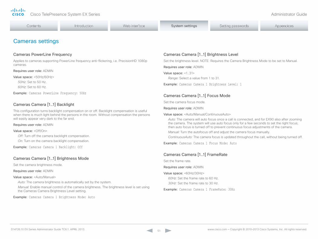
Cisco TelePresence System EX Series Administrator Guide
D14726.10 EX Series Administrator Guide TC6.1, APRIL 2013. www.cisco.com — Copyright © 2010–2013 Cisco Systems, Inc. All rights reserved. 51
Cameras settings
Cameras PowerLine FrequencyApplies to cameras supporting PowerLine frequency anti-flickering, i.e. PrecisionHD 1080p cameras.
Requires user role: ADmIn
Value space: <50Hz/60Hz>50Hz: Set to 50 Hz.60Hz: Set to 60 Hz.
Example: Cameras PowerLine Frequency: 50Hz
Cameras Camera [1..1] BacklightThis configuration turns backlight compensation on or off. Backlight compensation is useful when there is much light behind the persons in the room. Without compensation the persons will easily appear very dark to the far end.
Requires user role: ADmIn
Value space: <off/on>Off: Turn off the camera backlight compensation.On: Turn on the camera backlight compensation.
Example: Cameras Camera 1 Backlight: Off
Cameras Camera [1..1] Brightness ModeSet the camera brightness mode.
Requires user role: ADmIn
Value space: <Auto/manual>Auto: The camera brightness is automatically set by the system.Manual: Enable manual control of the camera brightness. The brightness level is set using the Cameras Camera Brightness Level setting.
Example: Cameras Camera 1 Brightness Mode: Auto
Cameras Camera [1..1] Brightness LevelSet the brightness level. noTE: Requires the Camera Brightness mode to be set to manual.
Requires user role: ADmIn
Value space: <1..31>Range: Select a value from 1 to 31.
Example: Cameras Camera 1 Brightness Level: 1
Cameras Camera [1..1] Focus ModeSet the camera focus mode.
Requires user role: ADmIn
Value space: <Auto/manual/ContinuousAuto>Auto: The camera will auto focus once a call is connected, and for EX90 also after zooming the camera. The system will use auto focus only for a few seconds to set the right focus; then auto focus is turned off to prevent continuous focus adjustments of the camera.Manual: Turn the autofocus off and adjust the camera focus manually.ContinuousAuto: The camera focus is updated throughout the call, without being turned off.
Example: Cameras Camera 1 Focus Mode: Auto
Cameras Camera [1..1] FrameRateSet the frame rate.
Requires user role: ADmIn
Value space: <60Hz/30Hz>60Hz: Set the frame rate to 60 Hz.30Hz: Set the frame rate to 30 Hz.
Example: Cameras Camera 1 FrameRate: 30Hz

Cisco TelePresence System EX Series Administrator Guide
D14726.10 EX Series Administrator Guide TC6.1, APRIL 2013. www.cisco.com — Copyright © 2010–2013 Cisco Systems, Inc. All rights reserved. 52
Cameras Camera [1..1] Gamma ModeThe Gamma mode setting enables gamma corrections. Gamma describes the nonlinear relationship between image pixels and monitor brightness.
Requires user role: ADmIn
Value space: <Auto/manual>Auto: Auto is the default and the recommended setting.Manual: In severe light conditions, you may switch mode to manual and specify explicitly which gamma table to use by setting the Gamma Level.
Example: Cameras Camera 1 Gamma Mode: Auto
Cameras Camera [1..1] Gamma LevelBy setting the Gamma Level you can select which gamma correction table to use. This setting may be useful in difficult lighting conditions, where changes to the brightness setting does not provide satisfactory results. noTE: Requires the Gamma mode to be set to manual.
Requires user role: ADmIn
Value space: <0..7>Range: Select a value from 0 to 7.
Example: Cameras Camera 1 Gamma Level: 0
Cameras Camera [1..1] Whitebalance ModeSet the camera whitebalance mode.
Requires user role: ADmIn
Value space: <Auto/manual>Auto: The camera will continuously adjust the whitebalance depending on the camera view.Manual: Enables manual control of the camera whitebalance. The whitebalance level is set using the Cameras Camera Whitebalance Level setting.
Example: Cameras Camera 1 Whitebalance Mode: Auto
Cameras Camera [1..1] Whitebalance LevelSet the whitebalance level. noTE: Requires the Camera Whitebalance mode to be set to manual.
Requires user role: ADmIn
Value space: <1..16>Range: Select a value from 1 to 16.
Example: Cameras Camera 1 Whitebalance Level: 1
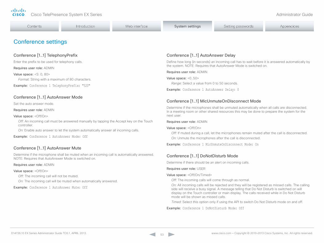
Cisco TelePresence System EX Series Administrator Guide
D14726.10 EX Series Administrator Guide TC6.1, APRIL 2013. www.cisco.com — Copyright © 2010–2013 Cisco Systems, Inc. All rights reserved. 53
Conference settings
Conference [1..1] TelephonyPrefixEnter the prefix to be used for telephony calls.
Requires user role: ADmIn
Value space: <S: 0, 80>Format: String with a maximum of 80 characters.
Example: Conference 1 TelephonyPrefix: "520"
Conference [1..1] AutoAnswer ModeSet the auto answer mode.
Requires user role: ADmIn
Value space: <off/on>Off: An incoming call must be answered manually by tapping the Accept key on the Touch controller.On: Enable auto answer to let the system automatically answer all incoming calls.
Example: Conference 1 AutoAnswer Mode: Off
Conference [1..1] AutoAnswer MuteDetermine if the microphone shall be muted when an incoming call is automatically answered. noTE: Requires that AutoAnswer mode is switched on.
Requires user role: ADmIn
Value space: <off/on>Off: The incoming call will not be muted.On: The incoming call will be muted when automatically answered.
Example: Conference 1 AutoAnswer Mute: Off
Conference [1..1] AutoAnswer DelayDefine how long (in seconds) an incoming call has to wait before it is answered automatically by the system. noTE: Requires that AutoAnswer mode is switched on.
Requires user role: ADmIn
Value space: <0..50>Range: Select a value from 0 to 50 seconds.
Example: Conference 1 AutoAnswer Delay: 0
Conference [1..1] MicUnmuteOnDisconnect ModeDetermine if the microphones shall be unmuted automatically when all calls are disconnected. In a meeting room or other shared resources this may be done to prepare the system for the next user.
Requires user role: ADmIn
Value space: <off/on>Off: If muted during a call, let the microphones remain muted after the call is disconnected.On: Unmute the microphones after the call is disconnected.
Example: Conference 1 MicUnmuteOnDisconnect Mode: On
Conference [1..1] DoNotDisturb ModeDetermine if there should be an alert on incoming calls.
Requires user role: USER
Value space: <off/on/Timed>Off: The incoming calls will come through as normal.On: All incoming calls will be rejected and they will be registered as missed calls. The calling side will receive a busy signal. A message telling that Do not Disturb is switched on will display on the Touch controller or main display. The calls received while in Do not Disturb mode will be shown as missed calls.Timed: Select this option only if using the API to switch Do not Disturb mode on and off.
Example: Conference 1 DoNotDisturb Mode: Off

Cisco TelePresence System EX Series Administrator Guide
D14726.10 EX Series Administrator Guide TC6.1, APRIL 2013. www.cisco.com — Copyright © 2010–2013 Cisco Systems, Inc. All rights reserved. 54
Conference [1..1] DoNotDisturb DefaultTimeoutThis setting determines the default duration of a Do not Disturb session, i.e. the period when incoming calls are rejected and registered as missed calls. The session can be terminated earlier by using the user interface (Touch controller) or the Conference DonotDisturb mode setting. The default value is 60 minutes.
Requires user role: ADmIn
Value space: <0..1440>Range: Select the number of minutes (between 0 and 1440, i.e. 24 hours) before the Do not Disturb session times out automatically.
Example: Conference 1 DoNotDisturb DefaultTimeOut: 60
Conference [1..1] FarEndControl ModeLets you decide if the remote side (far end) should be allowed to select your video sources and control your local camera (pan, tilt, zoom).
Requires user role: ADmIn
Value space: <off/on>Off: The far end is not allowed to select your video sources or to control your local camera (pan, tilt, zoom).On: Allows the far end to be able to select your video sources and control your local camera (pan, tilt, zoom). you will still be able to control your camera and select your video sources as normal.
Example: Conference 1 FarEndControl Mode: On
Conference [1..1] FarEndControl SignalCapabilitySet the far end control (H.224) signal capability mode.
Requires user role: ADmIn
Value space: <off/on>Off: Disable the far end control signal capability.On: Enable the far end control signal capability.
Example: Conference 1 FarEndControl SignalCapability: On
Conference [1..1] Encryption ModeSet the conference encryption mode. A padlock with the text "Encryption on" or "Encryption off" displays on screen for a few seconds when the conference starts.
Requires user role: ADmIn
Value space: <off/on/BestEffort>Off: The system will not use encryption.On: The system will only allow calls that are encrypted.BestEffort: The system will use encryption whenever possible. > In Point to point calls: If the far end system supports encryption (AES-128), the call will be encrypted. If not, the call will proceed without encryption. > In MultiSite calls: In order to have encrypted multiSite conferences, all sites must support encryption. If not, the conference will be unencrypted.
Example: Conference 1 Encryption Mode: BestEffort
Conference [1..1] DefaultCall ProtocolSet the Default Call Protocol to be used when placing calls from the system.
Requires user role: ADmIn
Value space: <H323/Sip/H320>H323: H323 ensures that calls are set up as H.323 calls.Sip: Sip ensures that calls are set up as SIP calls.H320: H320 ensures that calls are set up as H.320 calls (only applicable if connected to a Cisco TelePresence ISDn Link gateway).
Example: Conference 1 DefaultCall Protocol: H323
Conference [1..1] DefaultCall RateSet the Default Call Rate to be used when placing calls from the system.
Requires user role: ADmIn
Value space: <64..6000>Range: Select a value between 64 and 6000 kbps.
Example: Conference 1 DefaultCall Rate: 768
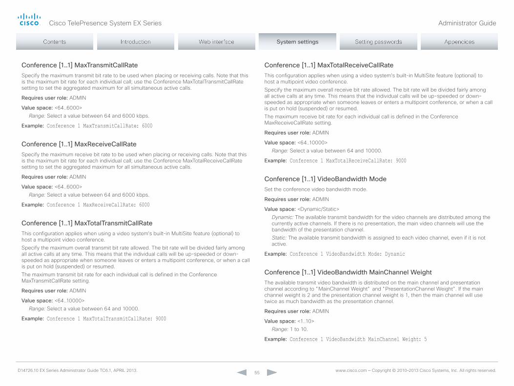
Cisco TelePresence System EX Series Administrator Guide
D14726.10 EX Series Administrator Guide TC6.1, APRIL 2013. www.cisco.com — Copyright © 2010–2013 Cisco Systems, Inc. All rights reserved. 55
Conference [1..1] MaxTransmitCallRateSpecify the maximum transmit bit rate to be used when placing or receiving calls. note that this is the maximum bit rate for each individual call; use the Conference maxTotalTransmitCallRate setting to set the aggregated maximum for all simultaneous active calls.
Requires user role: ADmIn
Value space: <64..6000>Range: Select a value between 64 and 6000 kbps.
Example: Conference 1 MaxTransmitCallRate: 6000
Conference [1..1] MaxReceiveCallRateSpecify the maximum receive bit rate to be used when placing or receiving calls. note that this is the maximum bit rate for each individual call; use the Conference maxTotalReceiveCallRate setting to set the aggregated maximum for all simultaneous active calls.
Requires user role: ADmIn
Value space: <64..6000>Range: Select a value between 64 and 6000 kbps.
Example: Conference 1 MaxReceiveCallRate: 6000
Conference [1..1] MaxTotalTransmitCallRateThis configuration applies when using a video system's built-in multiSite feature (optional) to host a multipoint video conference.Specify the maximum overall transmit bit rate allowed. The bit rate will be divided fairly among all active calls at any time. This means that the individual calls will be up-speeded or down-speeded as appropriate when someone leaves or enters a multipoint conference, or when a call is put on hold (suspended) or resumed.The maximum transmit bit rate for each individual call is defined in the Conference maxTransmitCallRate setting.
Requires user role: ADmIn
Value space: <64..10000>Range: Select a value between 64 and 10000.
Example: Conference 1 MaxTotalTransmitCallRate: 9000
Conference [1..1] MaxTotalReceiveCallRateThis configuration applies when using a video system's built-in multiSite feature (optional) to host a multipoint video conference.Specify the maximum overall receive bit rate allowed. The bit rate will be divided fairly among all active calls at any time. This means that the individual calls will be up-speeded or down-speeded as appropriate when someone leaves or enters a multipoint conference, or when a call is put on hold (suspended) or resumed.The maximum receive bit rate for each individual call is defined in the Conference maxReceiveCallRate setting.
Requires user role: ADmIn
Value space: <64..10000>Range: Select a value between 64 and 10000.
Example: Conference 1 MaxTotalReceiveCallRate: 9000
Conference [1..1] VideoBandwidth ModeSet the conference video bandwidth mode.
Requires user role: ADmIn
Value space: <Dynamic/Static>Dynamic: The available transmit bandwidth for the video channels are distributed among the currently active channels. If there is no presentation, the main video channels will use the bandwidth of the presentation channel.Static: The available transmit bandwidth is assigned to each video channel, even if it is not active.
Example: Conference 1 VideoBandwidth Mode: Dynamic
Conference [1..1] VideoBandwidth MainChannel WeightThe available transmit video bandwidth is distributed on the main channel and presentation channel according to "mainChannel Weight" and "PresentationChannel Weight". If the main channel weight is 2 and the presentation channel weight is 1, then the main channel will use twice as much bandwidth as the presentation channel.
Requires user role: ADmIn
Value space: <1..10>Range: 1 to 10.
Example: Conference 1 VideoBandwidth MainChannel Weight: 5
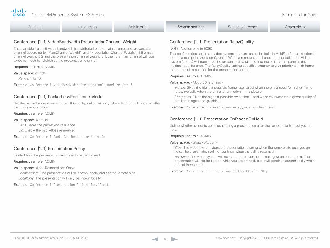
Cisco TelePresence System EX Series Administrator Guide
D14726.10 EX Series Administrator Guide TC6.1, APRIL 2013. www.cisco.com — Copyright © 2010–2013 Cisco Systems, Inc. All rights reserved. 56
Conference [1..1] VideoBandwidth PresentationChannel WeightThe available transmit video bandwidth is distributed on the main channel and presentation channel according to "mainChannel Weight" and "PresentationChannel Weight". If the main channel weight is 2 and the presentation channel weight is 1, then the main channel will use twice as much bandwidth as the presentation channel.
Requires user role: ADmIn
Value space: <1..10>Range: 1 to 10.
Example: Conference 1 VideoBandwidth PresentationChannel Weight: 5
Conference [1..1] PacketLossResilience ModeSet the packetloss resilience mode. This configuration will only take effect for calls initiated after the configuration is set.
Requires user role: ADmIn
Value space: <off/on>Off: Disable the packetloss resilience.On: Enable the packetloss resilience.
Example: Conference 1 PacketLossResilience Mode: On
Conference [1..1] Presentation PolicyControl how the presentation service is to be performed.
Requires user role: ADmIn
Value space: <LocalRemote/Localonly>LocalRemote: The presentation will be shown locally and sent to remote side.LocalOnly: The presentation will only be shown locally.
Example: Conference 1 Presentation Policy: LocalRemote
Conference [1..1] Presentation RelayQualitynoTE: Applies only to EX90.This configuration applies to video systems that are using the built-in multiSite feature (optional) to host a multipoint video conference. When a remote user shares a presentation, the video system (codec) will transcode the presentation and send it to the other participants in the multipoint conference. The RelayQuality setting specifies whether to give priority to high frame rate or to high resolution for the presentation source.
Requires user role: ADmIn
Value space: <motion/Sharpness>Motion: Gives the highest possible frame rate. Used when there is a need for higher frame rates, typically when there is a lot of motion in the picture.Sharpness: Gives the highest possible resolution. Used when you want the highest quality of detailed images and graphics.
Example: Conference 1 Presentation RelayQuality: Sharpness
Conference [1..1] Presentation OnPlacedOnHoldDefine whether or not to continue sharing a presentation after the remote site has put you on hold.
Requires user role: ADmIn
Value space: <Stop/noAction>Stop: The video system stops the presentation sharing when the remote site puts you on hold. The presentation will not continue when the call is resumed.NoAction: The video system will not stop the presentation sharing when put on hold. The presentation will not be shared while you are on hold, but it will continue automatically when the call is resumed.
Example: Conference 1 Presentation OnPlacedOnHold: Stop

Cisco TelePresence System EX Series Administrator Guide
D14726.10 EX Series Administrator Guide TC6.1, APRIL 2013. www.cisco.com — Copyright © 2010–2013 Cisco Systems, Inc. All rights reserved. 57
Conference [1..1] Multipoint ModeDefine how the video system handles multiparty video conferences.If registered to a Cisco TelePresence Video Communication Server (VCS), the video system can either use its own built-in multiSite feature (available only for EX90), or it can rely on the multiWay network solution. multiWay requires that the video network includes a multipoint control unit (mCU). If registered to a Cisco Unified Communications manager (CUCm) version 8.6.2 or newer, the video system can use either the CUCm conference bridge, or the video system's own built-in multiSite feature. Which one to use is set-up by CUCm.Both multiway and the CUCm conference bridge allows you to set up conferences with many participants. The multiSite feature allows up to four participants (yourself included) plus one additional audio call. note that the multiSite feature is optional and may not be available on all EX90 units. multiSite is not available for EX60.
Requires user role: ADmIn
Value space: <Auto/off/mulitSite/multiWay/CUCmmediaResourceGroupList>Auto: If a multiWay address is specified in the networkServices multiWay Address setting, multiWay takes priority over multiSite. If neither multiWay nor multiSite is available, the multipoint mode is set to off automatically.Off: multiparty conferences are not allowed.MultiSite: multiparty conferences are set up using multiSite. If multiSite is chosen when the multiSite feature is not available, the multipoint mode will be set to off.MultiWay: multiparty conferences are set up using multiWay. The multipoint mode will be set to off automatically if the multiWay service is unavailable, for example if a server address is not specified in the networkServices multiWay Address setting.CUCMMediaResourceGroupList: multiparty conferences (ad hoc conferences) are hosted by the CUCm configured conference bridge. This setting is provisioned by CUCm in a CUCm environment and should never be set manually by the user.
Example: Conference 1 Multipoint Mode: Auto
Conference [1..1] IncomingMultisiteCall ModeSelect whether or not to allow incoming calls when already in a call/conference.
Requires user role: ADmIn
Value space: <Allow/Deny>Allow: you will be notified when someone calls you while you are already in a call. you can accept the incoming call or not. The ongoing call may be put on hold while answering the incoming call; or you may merge the calls (requires multiSite or multiWay support).Deny: An incoming call will be rejected if you are already in a call. you will not be notified about the incoming call. However, the call will appear as a missed call in the call history list.
Example: Conference 1 IncomingMultisiteCall Mode: Allow

Cisco TelePresence System EX Series Administrator Guide
D14726.10 EX Series Administrator Guide TC6.1, APRIL 2013. www.cisco.com — Copyright © 2010–2013 Cisco Systems, Inc. All rights reserved. 58
FacilityService settings
FacilityService Service [1..5] TypeUp to five different facility services can be supported simultaneously. With this setting you can select what kind of services they are.A facility service is not available unless both the FacilityService Service name and the FacilityService Service number settings are properly set.only FacilityService Service 1 with Type Helpdesk is available on the Touch controller.
Requires user role: ADmIn
Value space: <other/Concierge/Helpdesk/Emergency/Security/Catering/Transportation>Other: Select this option for services not covered by the other options.Concierge: Select this option for concierge services.Helpdesk: Select this option for helpdesk services.Emergency: Select this option for emergency services.Security: Select this option for security services.Catering: Select this option for catering services.Transportation: Select this option for transportation services.
Example: FacilityService Service 1 Type: Helpdesk
FacilityService Service [1..5] NameSet the name of each facility service. Up to five different facility services are supported. A facility service is not available unless both the FacilityService Service name and the FacilityService Service number settings are properly set.only FacilityService Service 1 is available on the Touch controller, and its name is used on the facility service call button.
Requires user role: ADmIn
Value space: <S: 0, 255>Format: String with a maximum of 255 characters.
Example: FacilityService Service 1 Name: ""
FacilityService Service [1..5] NumberSet the number for each facility service. Up to five different facility services are supported.A facility service is not available unless both the FacilityService Service name and the FacilityService Service number settings are properly set.only FacilityService Service 1 is available on the Touch controller.
Requires user role: ADmIn
Value space: <S: 0, 255>Format: String with a maximum of 255 characters.
Example: FacilityService Service 1 Number: ""
FacilityService Service [1..5] CallTypeSet the call type for each facility service. Up to five different facility services are supported.A facility service is not available unless both the FacilityService Service name and the FacilityService Service number settings are properly set.only FacilityService Service 1 is available on the Touch controller.
Requires user role: ADmIn
Value space: <Video/Audio>Video: Select this option for video calls.Audio: Select this option for audio calls.
Example: FacilityService Service 1 CallType: Video

Cisco TelePresence System EX Series Administrator Guide
D14726.10 EX Series Administrator Guide TC6.1, APRIL 2013. www.cisco.com — Copyright © 2010–2013 Cisco Systems, Inc. All rights reserved. 59
H323 settings
H323 NAT ModeThe firewall traversal technology creates a secure path through the firewall barrier, and enables proper exchange of audio/video data when connected to an external video conferencing system (when the IP traffic goes through a nAT router). noTE: nAT does not work in conjunction with gatekeepers.
Requires user role: ADmIn
Value space: <Auto/off/on>Auto: The system will determine if the H323 nAT Address or the real IP address should be used in signaling. This makes it possible to place calls to endpoints on the LAn as well as endpoints on the WAn. If the H323 nAT Address is wrong or not set, the real IP address will be used.Off: The system will signal the real IP address.On: The system will signal the configured H323 nAT Address instead of its real IP address in Q.931 and H.245. The nAT Server Address will be shown in the startup-menu as: "my IP Address: 10.0.2.1". If the H323 nAT Address is wrong or not set, H.323 calls cannot be set up.
Example: H323 NAT Mode: Off
H323 NAT AddressEnter the external/global IP address to the router with nAT support. Packets sent to the router will then be routed to the system. note that nAT cannot be used when registered to a gatekeeper.In the router, the following ports must be routed to the system's IP address: * Port 1720 * Port 5555-6555 * Port 2326-2487
Requires user role: ADmIn
Value space: <S: 0, 64>Format: A valid IPv4 address or IPv6 address.
Example: H323 NAT Address: ""
H323 Profile [1..1] Authentication ModeSet the authenticatin mode for the H.323 profile.
Requires user role: ADmIn
Value space: <off/on>Off: If the H.323 Gatekeeper Authentication mode is set to off the system will not try to authenticate itself to a H.323 Gatekeeper, but will still try a normal registration.On: If the H.323 Gatekeeper Authentication mode is set to on and a H.323 Gatekeeper indicates that it requires authentication, the system will try to authenticate itself to the gatekeeper. noTE: Requires the Authentication Loginname and Authentication Password to be defined on both the codec and the Gatekeeper.
Example: H323 Profile 1 Authentication Mode: Off
H323 Profile [1..1] Authentication LoginNameThe system sends the Authentication Login name and the Authentication Password to a H.323 Gatekeeper for authentication. The authentication is a one way authentication from the codec to the H.323 Gatekeeper, i.e. the system is authenticated to the gatekeeper. If the H.323 Gatekeeper indicates that no authentication is required, the system will still try to register. noTE: Requires the H.323 Gatekeeper Authentication mode to be enabled.
Requires user role: ADmIn
Value space: <S: 0, 50>Format: String with a maximum of 50 characters.
Example: H323 Profile 1 Authentication LoginName: ""
Cisco TelePresence System EX Series Administrator Guide
D14726.10 EX Series Administrator Guide TC6.1, APRIL 2013. www.cisco.com — Copyright © 2010–2013 Cisco Systems, Inc. All rights reserved. 60
H323 Profile [1..1] Authentication PasswordThe system sends the Authentication Login name and the Authentication Password to a H.323 Gatekeeper for authentication. The authentication is a one way authentication from the codec to the H.323 Gatekeeper, i.e. the system is authenticated to the gatekeeper. If the H.323 Gatekeeper indicates that no authentication is required, the system will still try to register. noTE: Requires the H.323 Gatekeeper Authentication mode to be enabled.
Requires user role: ADmIn
Value space: <S: 0, 50>Format: String with a maximum of 50 characters.
Example: H323 Profile 1 Authentication Password: ""
H323 Profile [1..1] CallSetup ModeThe H.323 Call Setup mode defines whether to use a Gatekeeper or Direct calling when establishing H323 calls.noTE: Direct H.323 calls can be made even though the H.323 Call Setup mode is set to Gatekeeper.
Requires user role: ADmIn
Value space: <Direct/Gatekeeper>Direct: An IP address must be used when dialing in order to make the H323 call.Gatekeeper: The system will use a Gatekeeper to make a H.323 call. When selecting this option the H323 Profile Gatekeeper Address and H323 Profile Gatekeeper Discovery settings must also be configured.
Example: H323 Profile 1 CallSetup Mode: Gatekeeper
H323 Profile [1..1] Gatekeeper DiscoveryDetermine how the system shall register to a H.323 Gatekeeper.
Requires user role: ADmIn
Value space: <manual/Auto>Manual: The system will use a specific Gatekeeper identified by the Gatekeeper's IP address.Auto: The system will automatically try to register to any available Gatekeeper. If a Gatekeeper responds to the request sent from the codec within 30 seconds this specific Gatekeeper will be used. This requires that the Gatekeeper is in auto discovery mode as well. If no Gatekeeper responds, the system will not use a Gatekeeper for making H.323 calls and hence an IP address must be specified manually.
Example: H323 Profile 1 Gatekeeper Discovery: Manual
H323 Profile [1..1] Gatekeeper AddressEnter the IP address of the Gatekeeper. noTE: Requires the H.323 Call Setup mode to be set to Gatekeeper and the Gatekeeper Discovery to be set to manual.
Requires user role: ADmIn
Value space: <S: 0, 255>Format: A valid IPv4 address, IPv6 address or DnS name.
Example: H323 Profile 1 Gatekeeper Address: "192.0.2.0"
H323 Profile [1..1] H323Alias E164The H.323 Alias E.164 defines the address of the system, according to the numbering plan implemented in the H.323 Gatekeeper. The E.164 alias is equivalent to a telephone number, sometimes combined with access codes.
Requires user role: ADmIn
Value space: <S: 0, 30>Format: Compact string with a maximum of 30 characters. Valid characters are 0-9, * and #.
Example: H323 Profile 1 H323Alias E164: "90550092"
H323 Profile [1..1] H323Alias IDLets you specify the H.323 Alias ID which is used to address the system on a H.323 Gatekeeper and will be displayed in the call lists. Example: "[email protected]", "my H.323 Alias ID"
Requires user role: ADmIn
Value space: <S: 0, 49>Format: String with a maximum of 49 characters.
Example: H323 Profile 1 H323Alias ID: "[email protected]"

Cisco TelePresence System EX Series Administrator Guide
D14726.10 EX Series Administrator Guide TC6.1, APRIL 2013. www.cisco.com — Copyright © 2010–2013 Cisco Systems, Inc. All rights reserved. 61
H323 Profile [1..1] PortAllocationThe H.323 Port Allocation setting affects the H.245 port numbers used for H.323 call signalling.
Requires user role: ADmIn
Value space: <Dynamic/Static>Dynamic: The system will allocate which ports to use when opening a TCP connection. The reason for doing this is to avoid using the same ports for subsequent calls, as some firewalls consider this as a sign of attack. When Dynamic is selected, the H.323 ports used are from 11000 to 20999. once 20999 is reached they restart again at 11000. For RTP and RTCP media data, the system is using UDP ports in the range 2326 to 2487. Each media channel is using two adjacent ports, ie 2330 and 2331 for RTP and RTCP respectively. The ports are automatically selected by the system within the given range. Firewall administrators should not try to deduce which ports are used when, as the allocation schema within the mentioned range may change without any further notice.Static: When set to Static the ports are given within a static predefined range [5555-6555].
Example: H323 Profile 1 PortAllocation: Dynamic

Cisco TelePresence System EX Series Administrator Guide
D14726.10 EX Series Administrator Guide TC6.1, APRIL 2013. www.cisco.com — Copyright © 2010–2013 Cisco Systems, Inc. All rights reserved. 62
Network settings
Network [1..1] IPStackSelect which internet protocols the system will support.noTE: Restart the system after changing this setting.
Requires user role: ADmIn
Value space: <IPv4/IPv6>IPv4: IP version 4 is used for the SIP and H323 calls.IPv6: IP version 6 is used for the SIP and H323 calls.
Example: Network 1 IPStack: IPv4
Network [1..1] AssignmentDefine how the system will obtain its IPv4 address, subnet mask and gateway address. This setting only applies to systems on IPv4 networks.
Requires user role: ADmIn
Value space: <Static/DHCP>Static: The addresses must be configured manually using the network IPv4 Address, network IPv4 Gateway and network IPv4 Subnetmask settings (static addresses).DHCP: The system addresses are automatically assigned by the DHCP server.
Example: Network 1 Assignment: DHCP
Network [1..1] IPv4 AddressEnter the static IPv4 network address for the system. This setting is only applicable when network Assignment is set to Static.
Requires user role: ADmIn
Value space: <S: 0, 64>Format: A valid IPv4 address.
Example: Network 1 IPv4 Address: "192.0.2.0"
Network [1..1] IPv4 GatewayDefine the IPv4 network gateway. This setting is only applicable when the network Assignment is set to Static.
Requires user role: ADmIn
Value space: <S: 0, 64>Format: A valid IPv4 address.
Example: Network 1 IPv4 Gateway: "192.0.2.0"
Network [1..1] IPv4 SubnetMaskDefine the IPv4 network subnet mask. This setting is only applicable when the network Assignment is set to Static.
Requires user role: ADmIn
Value space: <S: 0, 64>Format: The valid IPv4 address format.
Example: Network 1 IPv4 SubnetMask: "255.255.255.0"
Network [1..1] IPv6 AssignmentDefine how the system will obtain its IPv6 address and the default gateway address. This setting only applies to systems on IPv6 networks.
Requires user role: ADmIn
Value space: <Static/DHCPv6/Autoconf>Static: The codec and gateway IP addresses must be configured manually using the network IPv6 Address and network IPv6 Gateway settings. The options, for example nTP and DnS server addresses, must either be set manually or obtained from a DHCPv6 server. The network IPv6 DHCPoptions setting determines which method to use.DHCPv6: All IPv6 addresses, including options, will be obtained from a DHCPv6 server. See RFC 3315 for a detailed description. The network IPv6 DHCPoptions setting will be ignored.Autoconf: Enable IPv6 stateless autoconfiguration of the IPv6 network interface. See RFC 4862 for a detailed description. The options, for example nTP and DnS server addresses, must either be set manually or obtained from a DHCPv6 server. The network IPv6 DHCPoptions setting determines which method to use.
Example: Network 1 IPv6 Assignment: Autoconf

Cisco TelePresence System EX Series Administrator Guide
D14726.10 EX Series Administrator Guide TC6.1, APRIL 2013. www.cisco.com — Copyright © 2010–2013 Cisco Systems, Inc. All rights reserved. 63
Network [1..1] IPv6 AddressEnter the static IPv6 network address for the system. This setting is only applicable when the network IPv6 Assignment is set to Static.
Requires user role: ADmIn
Value space: <S: 0, 64>Format: A valid IPv6 address.
Example: Network 1 IPv6 Address: "ffff:ffff:ffff:ffff:ffff:ffff:ffff:ffff"
Network [1..1] IPv6 GatewayDefine the IPv6 network gateway address. This setting is only applicable when the network IPv6 Assignment is set to Static.
Requires user role: ADmIn
Value space: <S: 0, 64>Format: A valid IPv6 address.
Example: Network 1 IPv6 Gateway: "ffff:ffff:ffff:ffff:ffff:ffff:ffff:ffff"
Network [1..1] IPv6 DHCPOptionsRetrieve a set of DHCP options, for example nTP and DnS server addresses, from a DHCPv6 server.
Requires user role: ADmIn
Value space: <off/on>Off: Disable the retrieval of DHCP options from a DHCPv6 server.On: Enable the retrieval of a selected set of DHCP options from a DHCPv6 server.
Example: Network 1 IPv6 DHCPOptions: On
Network [1..1] DHCP RequestTFTPServerAddressThis setting is used only for video systems that are registered to a Cisco Unified Communications manager (CUCm).The setting determines whether the endpoint should ask the DHCP server for DHCP option 150, so that it can discover the address of the TFTP server (provisioning server) automatically. If this setting is off or the DHCP server does not support option 150, the TFTP server address must be set manually using the Provisioning Externalmanager Address setting.note: If the network VLAn Voice mode setting is Auto and the Cisco Discovery Protocol (CDP) assigns an ID to the voice VLAn, then a request for option 150 will always be sent. That is, the network DHCP RequestTFTFServerAddress setting will be ignored.
Requires user role: ADmIn
Value space: <off/on>Off: The video system will not send a request for DHCP option 150 and the address of the TFTP server must be set manually. See the note above for any exception to this rule.On: The video system will send a request for option 150 to the DHCP server so that it can automatically discover the address of the TFTP server.
Example: Network 1 DHCP RequestTFTPServerAddress: Off
Network [1..1] DNS Domain NameDnS Domain name is the default domain name suffix which is added to unqualified names.Example: If the DnS Domain name is "company.com" and the name to lookup is "myVideoSystem", this will result in the DnS lookup "myVideoSystem.company.com".
Requires user role: ADmIn
Value space: <S: 0, 64>Format: String with a maximum of 64 characters.
Example: Network 1 DNS Domain Name: ""
Network [1..1] DNS Server [1..3] AddressDefine the network addresses for DnS servers. Up to 3 addresses may be specified. If the network addresses are unknown, contact your administrator or Internet Service Provider.
Requires user role: ADmIn
Value space: <S: 0, 64>Format: A valid IPv4 address or IPv6 address.
Example: Network 1 DNS Server 1 Address: ""

Cisco TelePresence System EX Series Administrator Guide
D14726.10 EX Series Administrator Guide TC6.1, APRIL 2013. www.cisco.com — Copyright © 2010–2013 Cisco Systems, Inc. All rights reserved. 64
Network [1..1] QoS ModeThe QoS (Quality of Service) is a method which handles the priority of audio, video and data in the network. The QoS settings must be supported by the infrastructure. Diffserv (Differentiated Services) is a computer networking architecture that specifies a simple, scalable and coarse-grained mechanism for classifying, managing network traffic and providing QoS priorities on modern IP networks.
Requires user role: ADmIn
Value space: <off/Diffserv>Off: no QoS method is used. Diffserv: When you set the QoS mode to Diffserv, the network QoS Diffserv Audio, network QoS Diffserv Video, network QoS Diffserv Data, network QoS Diffserv Signalling, network QoS Diffserv ICmPv6 and network QoS Diffserv nTP settings are used to prioritize packets.
Example: Network 1 QoS Mode: Diffserv
Network [1..1] QoS Diffserv Audionote: This setting will only take effect if network QoS mode is set to Diffserv.Define which priority Audio packets should have in the IP network.The priority for the packets ranges from 0 to 63 - the higher the number, the higher the priority. The recommended class for Audio is CS4, which equals the decimal value 32. If in doubt, contact your network administrator.The priority set here might be overridden when packets are leaving the network controlled by the local network administrator.
Requires user role: ADmIn
Value space: <0..63>Range: Select a value between 0 to 63 - the higher the number, the higher the priority. The default value is 0 (best effort).
Example: Network 1 QoS Diffserv Audio: 0
Network [1..1] QoS Diffserv Videonote: This setting will only take effect if network QoS mode is set to Diffserv.Define which priority Video packets should have in the IP network. The packets on the presentation channel (shared content) are also in the Video packet category. The priority for the packets ranges from 0 to 63 - the higher the number, the higher the priority. The recommended class for Video is CS4, which equals the decimal value 32. If in doubt, contact your network administrator.The priority set here might be overridden when packets are leaving the network controlled by the local network administrator.
Requires user role: ADmIn
Value space: <0..63>Range: Select a value between 0 to 63 - the higher the number, the higher the priority. The default value is 0 (best effort).
Example: Network 1 QoS Diffserv Video: 0
Network [1..1] QoS Diffserv Datanote: This setting will only take effect if network QoS mode is set to Diffserv.Define which priority Data packets should have in the IP network. The priority for the packets ranges from 0 to 63 - the higher the number, the higher the priority. The recommended value for Data is 0, which means best effort. If in doubt, contact your network administrator.The priority set here might be overridden when packets are leaving the network controlled by the local network administrator.
Requires user role: ADmIn
Value space: <0..63>Range: Select a value between 0 to 63 - the higher the number, the higher the priority. The default value is 0 (best effort).
Example: Network 1 QoS Diffserv Data: 0

Cisco TelePresence System EX Series Administrator Guide
D14726.10 EX Series Administrator Guide TC6.1, APRIL 2013. www.cisco.com — Copyright © 2010–2013 Cisco Systems, Inc. All rights reserved. 65
Network [1..1] QoS Diffserv Signallingnote: This setting will only take effect if network QoS mode is set to Diffserv.Define which priority Signalling packets that are deemed critical (time-sensitive) for the real-time operation should have in the IP network. The priority for the packets ranges from 0 to 63 - the higher the number, the higher the priority. The recommended class for Signalling is CS3, which equals the decimal value 24. If in doubt, contact your network administrator.The priority set here might be overridden when packets are leaving the network controlled by the local network administrator.
Requires user role: ADmIn
Value space: <0..63>Range: Select a value between 0 to 63 - the higher the number, the higher the priority. The default value is 0 (best effort).
Example: Network 1 QoS Diffserv Signalling: 0
Network [1..1] QoS Diffserv ICMPv6note: This setting will only take effect if network QoS mode is set to Diffserv.Define which priority ICmPv6 packets should have in the IP network. The priority for the packets ranges from 0 to 63 - the higher the number, the higher the priority. The recommended value for ICmPv6 is 0, which means best effort. If in doubt, contact your network administrator.The priority set here might be overridden when packets are leaving the network controlled by the local network administrator.
Requires user role: ADmIn
Value space: <0..63>Range: Select a value between 0 to 63 - the higher the number, the higher the priority. The default value is 0 (best effort).
Example: Network 1 QoS Diffserv ICMPv6: 0
Network [1..1] QoS Diffserv NTPnote: This setting will only take effect if network QoS mode is set to Diffserv.Define which priority nTP packets should have in the IP network. The priority for the packets ranges from 0 to 63 - the higher the number, the higher the priority. The recommended value for nTP is 0, which means best effort. If in doubt, contact your network administrator.The priority set here might be overridden when packets are leaving the network controlled by the local network administrator.
Requires user role: ADmIn
Value space: <0..63>Range: Select a value between 0 to 63 - the higher the number, the higher the priority. The default value is 0 (best effort).
Example: Network 1 QoS Diffserv NTP: 0
Network [1..1] IEEE8021X ModeThe system can be connected to an IEEE 802.1X LAn network, with a port-based network access control that is used to provide authenticated network access for Ethernet networks.
Requires user role: ADmIn
Value space: <off/on>Off: The 802.1X authentication is disabled (default).On: The 802.1X authentication is enabled.
Example: Network 1 IEEE8021X Mode: Off
Cisco TelePresence System EX Series Administrator Guide
D14726.10 EX Series Administrator Guide TC6.1, APRIL 2013. www.cisco.com — Copyright © 2010–2013 Cisco Systems, Inc. All rights reserved. 66
Network [1..1] IEEE8021X TlsVerifyVerification of the server-side certificate of an IEEE802.1x connection against the certificates in the local CA-list when TLS is used. The CA-list must be uploaded to the video system.This setting takes effect only when network [1..1] IEEE8021X Eap Tls is enabled (on).
Requires user role: ADmIn
Value space: <off/on>Off: When set to off, TLS connections are allowed without verifying the server-side X.509 certificate against the local CA-list. This should typically be selected if no CA-list has been uploaded to the codec.On: When set to on, the server-side X.509 certificate will be validated against the local CA-list for all TLS connections. only servers with a valid certificate will be allowed.
Example: xConfiguration Network 1 IEEE8021X TlsVerify: Off
Network [1..1] IEEE8021X UseClientCertificateAuthentication using a private key/certificate pair during an IEEE802.1x connection. The authentication X.509 certificate must be uploaded to the video system.
Requires user role: ADmIn
Value space: <off/on>Off: When set to off client-side authentication is not used (only server-side).On: When set to on the client (video system) will perform a mutual authentication TLS handshake with the server.
Example: Network 1 IEEE8021X UseClientCertificate: Off
Network [1..1] IEEE8021X IdentityThe 802.1X Identity is the user name needed for 802.1X authentication.
Requires user role: ADmIn
Value space: <S: 0, 64>Format: String with a maximum of 64 characters.
Example: Network 1 IEEE8021X Identity: ""
Network [1..1] IEEE8021X PasswordThe 802.1X Password is the password needed for 802.1X authentication.
Requires user role: ADmIn
Value space: <S: 0, 32>Format: String with a maximum of 32 characters.
Example: Network 1 IEEE8021X Password: ""
Network [1..1] IEEE8021X AnonymousIdentityThe 802.1X Anonymous ID string is to be used as unencrypted identity with EAP (Extensible Authentication Protocol) types that support different tunneled identity, like EAP-PEAP and EAP-TTLS. If set, the anonymous ID will be used for the initial (unencrypted) EAP Identity Request.
Requires user role: ADmIn
Value space: <S: 0, 64>Format: String with a maximum of 64 characters.
Example: Network 1 IEEE8021X AnonymousIdentity: ""
Network [1..1] IEEE8021X Eap Md5Set the md5 (message-Digest Algorithm 5) mode. This is a Challenge Handshake Authentication Protocol that relies on a shared secret. md5 is a Weak security.
Requires user role: ADmIn
Value space: <off/on>Off: The EAP-mD5 protocol is disabled.On: The EAP-mD5 protocol is enabled (default).
Example: Network 1 IEEE8021X Eap Md5: On
Cisco TelePresence System EX Series Administrator Guide
D14726.10 EX Series Administrator Guide TC6.1, APRIL 2013. www.cisco.com — Copyright © 2010–2013 Cisco Systems, Inc. All rights reserved. 67
Network [1..1] IEEE8021X Eap TtlsSet the TTLS (Tunneled Transport Layer Security) mode. Authenticates LAn clients without the need for client certificates. Developed by Funk Software and Certicom. Usually supported by Agere Systems, Proxim and Avaya.
Requires user role: ADmIn
Value space: <off/on>Off: The EAP-TTLS protocol is disabled.On: The EAP-TTLS protocol is enabled (default).
Example: Network 1 IEEE8021X Eap Ttls: On
Network [1..1] IEEE8021X Eap TlsEnable or disable the use of EAP-TLS (Transport Layer Security) for IEEE802.1x connections. The EAP-TLS protocol, defined in RFC 5216, is considered one of the most secure EAP standards. LAn clients are authenticated using client certificates.
Requires user role: ADmIn
Value space: <off/on>Off: The EAP-TLS protocol is disabled.On: The EAP-TLS protocol is enabled (default).
Example: Network 1 IEEE8021X Eap Tls: On
Network [1..1] IEEE8021X Eap PeapSet the Peap (Protected Extensible Authentication Protocol) mode. Authenticates LAn clients without the need for client certificates. Developed by microsoft, Cisco and RSA Security.
Requires user role: ADmIn
Value space: <off/on>Off: The EAP-PEAP protocol is disabled.On: The EAP-PEAP protocol is enabled (default).
Example: Network 1 IEEE8021X Eap Peap: On
Network [1..1] MTUSet the Ethernet mTU (maximum Transmission Unit).
Requires user role: ADmIn
Value space: <576..1500>Range: Select a value from 576 to 1500 bytes.
Example: Network 1 MTU: 1500
Network [1..1] SpeedSet the Ethernet link speed.noTE: If running older software versions than TC6.0, restart the system for any change to this setting to take effect.
Requires user role: ADmIn
Value space: <Auto/10half/10full/100half/100full/1000full>Auto: Autonegotiate link speed.10half: Force link to 10 mbps half-duplex.10full: Force link to 10 mbps full-duplex.100half: Force link to 100 mbps half-duplex.100full: Force link to 100 mbps full-duplex.1000full: Force link to 1 Gbps full-duplex.
Example: Network 1 Speed: Auto
Network [1..1] TrafficControl ModeSet the network traffic control mode to decide how to control the video packets transmission speed.
Requires user role: ADmIn
Value space: <off/on>Off: Transmit video packets at link speed.On: Transmit video packets at maximum 20 mbps. Can be used to smooth out bursts in the outgoing network traffic.
Example: Network 1 TrafficControl: On

Cisco TelePresence System EX Series Administrator Guide
D14726.10 EX Series Administrator Guide TC6.1, APRIL 2013. www.cisco.com — Copyright © 2010–2013 Cisco Systems, Inc. All rights reserved. 68
Network [1..1] RemoteAccess AllowFilter IP addresses for access to ssh/telnet/HTTP/HTTPS.
Requires user role: ADmIn
Value space: <S: 0, 255>Format: String with a maximum of 255 characters, comma separated IP adresses or IP range.
Example: Network 1 RemoteAccess Allow: "192.168.1.231, 192.168.1.182"
Network [1..1] VLAN Voice ModeSet the VLAn voice mode. The VLAn Voice mode will be set to Auto automatically if you choose Cisco UCm (Cisco Unified Communications manager) as provisioning infrastructure via the Provisioning Wizard on the Touch controller.
Requires user role: ADmIn
Value space: <Auto/manual/off>Auto: The Cisco Discovery Protocol (CDP), if available, assigns an id to the voice VLAn. If CDP is not available, VLAn is not enabled. Manual: The VLAn ID is set manually using the network VLAn Voice VlanId setting. If CDP is available, the manually set value will be overruled by the value assigned by CDP.Off: VLAn is not enabled.
Example: Network 1 VLAN Voice Mode: Off
Network [1..1] VLAN Voice VlanIdSet the VLAn voice ID. This setting will only take effect if VLAn Voice mode is set to manual.
Requires user role: ADmIn
Value space: <1..4094>Range: Select a value from 1 to 4094.
Example: Network 1 VLAN Voice VlanId: 1
Cisco TelePresence System EX Series Administrator Guide
D14726.10 EX Series Administrator Guide TC6.1, APRIL 2013. www.cisco.com — Copyright © 2010–2013 Cisco Systems, Inc. All rights reserved. 69
NetworkServices settings
NetworkServices XMLAPI Modenot applicable in this version.
NetworkServices MultiWay AddressThe multiWay address must be equal to the Conference Factory Alias, as configured on the Video Communication Server. The multiway™ conferencing enables video endpoint users to introduce a 3rd party into an existing call.multiway™ can be used in the following situations:1) When you want to add someone else in to your existing call.2) When you are called by a 3rd party while already in a call and you want to include that person in the call.Requirements: The EX90/EX60 must run software version TC4.2 (or later), Video Communication Server (VCS) version X5 (or later) and Codian mCU version 3.1 (or later). Video systems invited to join the multiway™ conference must support the H.323 routeTomC facility message if in an H.323 call, or SIP REFER message if in a SIP call.
Requires user role: ADmIn
Value space: <S: 0, 255>Format: String with a maximum of 255 characters (a valid dial URI).
Example: NetworkServices MultiWay Address: "h323:[email protected]"
NetworkServices MultiWay ProtocolDetermine the protocol to be used for multiWay calls.
Requires user role: ADmIn
Value space: <Auto/H323/Sip>Auto: The system will select the protocol for multiWay calls.H323: The H323 protocol will be used for multiWay calls.Sip: The SIP protocol will be used for multiWay calls.
Example: NetworkServices MultiWay Protocol: Auto
NetworkServices H323 ModeDetermine whether the system should be able to place and receive H.323 calls or not.
Requires user role: ADmIn
Value space: <off/on>Off: Disable the possibility to place and receive H.323 calls.On: Enable the possibility to place and receive H.323 calls (default).
Example: NetworkServices H323 Mode: On
NetworkServices HTTP ModeSet the HTTP mode to enable/disable access to the system through a web browser. The web interface is used for system management, call management such as call transfer, diagnostics and software uploads.noTE: Restart the system for any change to this setting to take effect.
Requires user role: ADmIn
Value space: <off/on>Off: The HTTP protocol is disabled.On: The HTTP protocol is enabled.
Example: NetworkServices HTTP Mode: On
NetworkServices HTTPS ModeHTTPS is a web protocol that encrypts and decrypts user page requests as well as the pages that are returned by the web server.noTE: Restart the system for any change to this setting to take effect.
Requires user role: ADmIn
Value space: <off/on>Off: The HTTPS protocol is disabled.On: The HTTPS protocol is enabled.
Example: NetworkServices HTTPS Mode: On
Cisco TelePresence System EX Series Administrator Guide
D14726.10 EX Series Administrator Guide TC6.1, APRIL 2013. www.cisco.com — Copyright © 2010–2013 Cisco Systems, Inc. All rights reserved. 70
NetworkServices HTTPS VerifyServerCertificateWhen the video system connects to an external HTTPS server (like a phone book server or an external manager), this server will present a certificate to the video system to identify itself.
Requires user role: ADmIn
Value space: <off/on>Off: Do not verify server certificates.On: Requires the system to verify that the server certificate is signed by a trusted Certificate Authority (CA). This requires that a list of trusted CAs are uploaded to the system in advance.
Example: NetworkServices HTTPS VerifyServerCertificate: Off
NetworkServices HTTPS VerifyClientCertificateWhen the video system connects to a HTTPS client (like a web browser), the client can be asked to present a certificate to the video system to identify itself.
Requires user role: ADmIn
Value space: <off/on>Off: Do not verify client certificates.On: Requires the client to present a certificate that is signed by a trusted Certificate Authority (CA). This requires that a list of trusted CAs are uploaded to the system in advance.
Example: NetworkServices HTTPS VerifyClientCertificate: Off
NetworkServices HTTPS OCSP ModeDefine the support for oCSP (online Certificate Status Protocol) responder services. The oCSP feature allows users to enable oCSP instead of certificate revocation lists (CRLs) to check the certificate status.For any outgoing HTTPS connection, the oCSP responder is queried of the status. If the corresponding certificate has been revoked, then the HTTPS connection will not be used.
Requires user role: ADmIn
Value space: <off/on>Off: Disable oCSP support.On: Enable oCSP support.
Example: NetworkServices HTTPS OCSP Mode: Off
NetworkServices HTTPS OCSP URLSpecify the URL of the oCSP responder (server) that will be used to check the certificate status.
Requires user role: ADmIn
Value space: <S: 0, 255>Format: String with a maximum of 255 characters.
Example: NetworkServices HTTPS OCSP URL: "http://ocspserver.company.com:81"
NetworkServices NTP ModeThe network Time Protocol (nTP) is used to synchronize the time of the system to a reference time server. The time server will subsequently be queried every 24th hour for time updates. The time will be displayed on the top of the screen. The system will use the time to timestamp messages transmitted to Gatekeepers or Border Controllers requiring H.235 authentication. The system will use the time to timestamp messages transmitted to Gatekeepers or Border Controllers that requires H.235 authentication. It is also used for timestamping Placed Calls, missed Calls and Received Calls.
Requires user role: ADmIn
Value space: <Auto/off/manual>Auto: The system will use the nTP server, by which address is supplied from the DHCP server in the network. If no DHCP server is used, or the DHCP server does not provide the system with a nTP server address, the system will use the static defined nTP server address specified by the user.Off: The system will not use an nTP server.Manual: The system will always use the static defined nTP server address specified by the user.
Example: NetworkServices NTP Mode: Manual
NetworkServices NTP AddressEnter the nTP Address to define the network time protocol server address. This address will be used if nTP mode is set to manual, or if set to Auto and no address is supplied by a DHCP server.
Requires user role: ADmIn
Value space: <S: 0, 64>Format: A valid IPv4 address, IPv6 address or DnS name.
Example: NetworkServices NTP Address: "1.ntp.tandberg.com"

Cisco TelePresence System EX Series Administrator Guide
D14726.10 EX Series Administrator Guide TC6.1, APRIL 2013. www.cisco.com — Copyright © 2010–2013 Cisco Systems, Inc. All rights reserved. 71
NetworkServices SIP ModeDetermine whether the system should be able to place and receive SIP calls or not.
Requires user role: ADmIn
Value space: <off/on>Off: Disable the possibility to place and receive SIP calls.On: Enable the possibility to place and receive SIP calls (default).
Example: NetworkServices SIP Mode: On
NetworkServices SNMP ModeSnmP (Simple network management Protocol) is used in network management systems to monitor network-attached devices (routers, servers, switches, projectors, etc) for conditions that warrant administrative attention. SnmP exposes management data in the form of variables on the managed systems, which describe the system configuration. These variables can then be queried (set to Readonly) and sometimes set (set to ReadWrite) by managing applications.
Requires user role: ADmIn
Value space: <off/Readonly/ReadWrite>Off: Disable the SnmP network service.ReadOnly: Enable the SnmP network service for queries only.ReadWrite: Enable the SnmP network service for both queries and commands.
Example: NetworkServices SNMP Mode: ReadWrite
NetworkServices SNMP Host [1..3] AddressEnter the address of up to three SnmP managers.The system's SnmP Agent (in the codec) responds to requests from SnmP managers (a PC program etc.), for example about system location and system contact. SnmP traps are not supported.
Requires user role: ADmIn
Value space: <S: 0, 64>Format: A valid IPv4 address, IPv6 address or DnS name.
Example: NetworkServices SNMP Host 1 Address: ""
NetworkServices SNMP CommunityNameEnter the name of the network Services SnmP Community. SnmP Community names are used to authenticate SnmP requests. SnmP requests must have a password (case sensitive) in order to receive a response from the SnmP Agent in the codec. The default password is "public". If you have the Cisco TelePresence management Suite (TmS) you must make sure the same SnmP Community is configured there too. noTE: The SnmP Community password is case sensitive.
Requires user role: ADmIn
Value space: <S: 0, 50>Format: String with a maximum of 50 characters.
Example: NetworkServices SNMP CommunityName: "public"
NetworkServices SNMP SystemContactEnter the name of the network Services SnmP System Contact.
Requires user role: ADmIn
Value space: <S: 0, 50>Format: String with a maximum of 50 characters.
Example: NetworkServices SNMP SystemContact: ""
NetworkServices SNMP SystemLocationEnter the name of the network Services SnmP System Location.
Requires user role: ADmIn
Value space: <S: 0, 50>Format: String with a maximum of 50 characters.
Example: NetworkServices SNMP SystemLocation: ""

Cisco TelePresence System EX Series Administrator Guide
D14726.10 EX Series Administrator Guide TC6.1, APRIL 2013. www.cisco.com — Copyright © 2010–2013 Cisco Systems, Inc. All rights reserved. 72
NetworkServices SSH ModeSSH (or Secure Shell) protocol can provide secure encrypted communication between the codec and your local computer.
Requires user role: ADmIn
Value space: <off/on>Off: The SSH protocol is disabled.On: The SSH protocol is enabled.
Example: NetworkServices SSH Mode: On
NetworkServices SSH AllowPublicKeySecure Shell (SSH) public key authentication can be used to access the codec.
Requires user role: ADmIn
Value space: <off/on>Off: The SSH public key is not allowed.On: The SSH public key is allowed.
Example: NetworkServices SSH AllowPublicKey: On
NetworkServices Telnet ModeTelnet is a network protocol used on the Internet or Local Area network (LAn) connections.
Requires user role: ADmIn
Value space: <off/on>Off: The Telnet protocol is disabled. This is the factory setting.On: The Telnet protocol is enabled.
Example: NetworkServices Telnet Mode: Off
NetworkServices CTMS Mode This setting determines whether or not to allow multiparty conferences controlled by a Cisco TelePresence multipoint Switch (CTmS). Video systems running software TC5.0 or later are able to initiate or join non-encrypted multiparty conferences controlled by CTmS version 1.8 or later. Encrypted conferences are supported as from software versions TC6.0 and CTmS 1.9.1. Encryption is addressed in the networkServices CTmS Encryption setting.
Requires user role: ADmIn
Value space: <off/on>Off: mulitparty conferencing via CTmS is prohibited.On: mulitparty conferencing via CTmS is allowed.
Example: NetworkServices CTMS Mode: On
NetworkServices CTMS EncryptionThis setting indicates whether or not the video system supports encryption when participating in a multiparty meeting controlled by a Cisco TelePresence multipoint Switch (CTmS).CTmS allows three security settings for meetings: non-secure (not encrypted), best effort (encrypted if all participants support encryption, otherwise not encrypted) and secure (always encrypted).
Requires user role: ADmIn
Value space: <off/BestEffort>Off: The video system does not allow encryption and therefore cannot participate in a secure CTmS meeting (encrypted). When participating in a best effort CTmS meeting, the meeting will be downgraded to non-secure (not encrypted).BestEffort: The video system can negotiate encryption parameters with CTmS and participate in a secure CTmS meeting (encrypted). Do not use this value if the CTmS version is older than 1.9.1.
Example: NetworkServices CTMS Encryption: Off

Cisco TelePresence System EX Series Administrator Guide
D14726.10 EX Series Administrator Guide TC6.1, APRIL 2013. www.cisco.com — Copyright © 2010–2013 Cisco Systems, Inc. All rights reserved. 73
Phonebook settings
Phonebook Server [1..1] IDEnter a name for the external phone book.
Requires user role: ADmIn
Value space: <S: 0, 64>Format: String with a maximum of 64 characters.
Example: Phonebook Server 1 ID: ""
Phonebook Server [1..1] TypeSelect the phonebook server type.
Requires user role: ADmIn
Value space: <VCS/TmS/Callway/CUCm>VCS: Select VCS if the phonebook is located on the Cisco TelePresence Video Communication Server.TMS: Select TmS if the phonebook is located on the Cisco TelePresence management Suite server.Callway: Select Callway if the phonebook is to be provided by the WebEx TelePresence subscription service (formerly called CallWay). Contact your WebEx TelePresence provider for more information.CUCM: Select CUCm if the phonebook is located on the Cisco Unified Communications manager.
Example: Phonebook Server 1 Type: TMS
Phonebook Server [1..1] URLEnter the address (URL) to the external phone book server.
Requires user role: ADmIn
Value space: <S: 0, 255>Format: String with a maximum of 255 characters.
Example: Phonebook Server 1 URL: "http://tms.company.com/tms/public/external/phonebook/phonebookservice.asmx"
Cisco TelePresence System EX Series Administrator Guide
D14726.10 EX Series Administrator Guide TC6.1, APRIL 2013. www.cisco.com — Copyright © 2010–2013 Cisco Systems, Inc. All rights reserved. 74
Provisioning settings
Provisioning ConnectivityThis setting controls how the device discovers whether it should request an internal or external configuration from the provisioning server.
Requires user role: ADmIn
Value space: <Internal/External/Auto>Internal: Request internal configuration.External: Request external configuration.Auto: Automatically discover using nAPTR queries whether internal or external configurations should be requested. If the nAPTR responses have the "e" flag, external configurations will be requested. otherwise internal configurations will be requested.
Example: Provisioning Connectivity: Auto
Provisioning ModeIt is possible to configure a video system using a provisioning system (external manager). This allows video conferencing network administrators to manage many video systems simultaneously.With this setting you choose which type of provisioning system to use. Provisioning can also be switched off. Contact your provisioning system provider/representative for more information.
Requires user role: ADmIn
Value space: <off/TmS/VCS/CallWay/CUCm/Auto>Off: The video system will not be configured by a provisioning system.TMS: The video system will be configured using TmS (Cisco TelePresence management System).VCS: The video system will be configured using VCS (Cisco TelePresence Video Communication Server).Callway: The video system will be configured using the WebEx TelePresence subscription service (formerly called Callway).CUCM: The video system will be configured using CUCm (Cisco Unified Communications manager).Auto: The provisioning server will automatically be selected by the video system.
Example: Provisioning Mode: TMS
Provisioning LoginNameThis is the user name part of the credentials used to authenticate the video system with the provisioning server. This setting must be used when required by the provisioning server. If Provisioning mode is Callway (WebEx TelePresence), enter the video number.
Requires user role: ADmIn
Value space: <S: 0, 80>Format: String with a maximum of 80 characters.
Example: Provisioning LoginName: ""
Provisioning PasswordThis is the password part of the credentials used to authenticate the video system with the provisioning server. This setting must be used when required by the provisioning server. If Provisioning mode is Callway (WebEx TelePresence), enter the activation code.
Requires user role: ADmIn
Value space: <S: 0, 64>Format: String with a maximum of 64 characters.
Example: Provisioning Password: ""
Provisioning HttpMethodSelect the HTTP method to be used for the provisioning.
Requires user role: ADmIn
Value space: <GET/PoST>GET: Select GET when the provisioning server supports GET.POST: Select PoST when the provisioning server supports PoST.
Example: Provisioning HttpMethod: POST

Cisco TelePresence System EX Series Administrator Guide
D14726.10 EX Series Administrator Guide TC6.1, APRIL 2013. www.cisco.com — Copyright © 2010–2013 Cisco Systems, Inc. All rights reserved. 75
Provisioning ExternalManager AddressEnter the IP Address or DnS name of the external manager / provisioning system. If an External manager Address (and Path) is configured, the system will send a message to this address when starting up. When receiving this message the external manager / provisioning system can return configurations/commands to the unit as a result. When using CUCm or TmS provisioning, the DHCP server can be set up to provide the external manager address automatically (DHCP option 242 for TmS, and DHCP option 150 for CUCm). An address set in the Provisioning Externalmanager Address setting will override the address provided by DHCP.
Requires user role: ADmIn
Value space: <S: 0, 64>Format: A valid IPv4 address, IPv6 address or DnS name.
Example: Provisioning ExternalManager Address: ""
Provisioning ExternalManager ProtocolDetermine whether to use secure management or not.
Requires user role: ADmIn
Value space: <HTTP/HTTPS>HTTP: Set to HTTP to disable secure management. Requires HTTP to be enabled in the networkServices HTTP mode setting.HTTPS: Set to HTTPS to enable secure management. Requires HTTPS to be enabled in the networkServices HTTPS mode setting.
Example: Provisioning ExternalManager Protocol: HTTP
Provisioning ExternalManager PathSet the Path to the external manager / provisioning system. This setting is required when several management services reside on the same server, i.e. share the same External manager address.
Requires user role: ADmIn
Value space: <S: 0, 255>Format: String with a maximum of 255 characters.
Example: Provisioning ExternalManager Path: "tms/public/external/management/SystemManagementService.asmx"
Provisioning ExternalManager DomainEnter the SIP domain for the VCS provisioning server.
Requires user role: ADmIn
Value space: <S: 0, 64>Format: String with a maximum of 64 characters.
Example: Provisioning ExternalManager Domain: "any.domain.com"
Cisco TelePresence System EX Series Administrator Guide
D14726.10 EX Series Administrator Guide TC6.1, APRIL 2013. www.cisco.com — Copyright © 2010–2013 Cisco Systems, Inc. All rights reserved. 76
RTP settings
RTP Ports Range StartSpecify the first port in the range of RTP ports. Also see the H323 Profile [1..1] PortAllocation setting.noTE: Restart the system for any change to this setting to take effect.
Requires user role: ADmIn
Value space: <1024..65502>Range: Select a value from 1024 to 65502.
Example: RTP Ports Range Start: 2326
RTP Ports Range StopSpecify the last RTP port in the range. Also see the H323 Profile [1..1] PortAllocation setting.noTE: Restart the system for any change to this setting to take effect.
Requires user role: ADmIn
Value space: <1056..65535>Range: Select a value from 1056 to 65535.
Example: RTP Ports Range Stop: 2486
Cisco TelePresence System EX Series Administrator Guide
D14726.10 EX Series Administrator Guide TC6.1, APRIL 2013. www.cisco.com — Copyright © 2010–2013 Cisco Systems, Inc. All rights reserved. 77
Security settings
Security Audit Logging ModeDetermine where to record or transmit the audit logs. When using the External or ExternalSecure modes, you also must enter the address and port number for the audit server in the Security Audit Server Address and Security Audit Server Port settings.noTE: Restart the system for any change to this setting to take effect.
Requires user role: AUDIT
Value space: <off/Internal/External/ExternalSecure>Off: no audit logging is performed.Internal: The system records the audit logs to internal logs, and rotates logs when they are full.External: The system sends the audit logs to an external audit server (syslog server). The audit server must support TCP.ExternalSecure: The system sends encrypted audit logs to an external audit server (syslog server) that is verified by a certificate in the Audit CA list. The Audit CA list file must be uploaded to the codec using the web interface. The common_name parameter of a certificate in the CA list must match the IP address of the audit server.
Example: Security Audit Logging Mode: Off
Security Audit Server AddressEnter the IP address of the audit server. only valid IPv4 or IPv6 address formats are accepted. Host names are not supported. This setting is only relevant when Security Audit Logging mode is set to External or ExternalSecure.noTE: Restart the system for any change to this setting to take effect.
Requires user role: AUDIT
Value space: <S: 0, 64>Format: A valid IPv4 address or IPv6 address.
Example: Security Audit Server Address: ""
Security Audit Server PortEnter the port of the audit server that the system shall send its audit logs to. The default port is 514. This setting is only relevant when Security Audit Logging mode is set to External or ExternalSecure.noTE: Restart the system for any change to this setting to take effect.
Requires user role: AUDIT
Value space: <0..65535>Range: Select a value from 0 to 65535.
Example: Security Audit Server Port: 514
Security Audit OnError ActionDetermine what happens when the connection to the audit server is lost. This setting is only relevant when Security Audit Logging mode is set to ExternalSecure.noTE: Restart the system for any change to this setting to take effect.
Requires user role: AUDIT
Value space: <Halt/Ignore>Halt: If a halt condition is detected the system is rebooted and only the auditor is allowed to operate the unit until the halt condition has passed. When the halt condition has passed the audit logs are re-spooled to the audit server. Halt conditions are: A network breach (no physical link), no audit server running (or wrong audit server address or port), TLS authentication failed (if in use), local backup (re-spooling) log full.Ignore: The system will continue its normal operation, and rotate internal logs when full. When the connection is restored it will again send its audit logs to the audit server.
Example: Security Audit OnError Action: Ignore
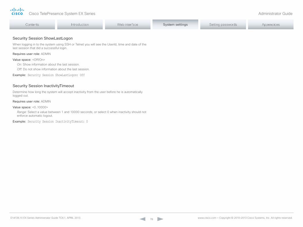
Cisco TelePresence System EX Series Administrator Guide
D14726.10 EX Series Administrator Guide TC6.1, APRIL 2013. www.cisco.com — Copyright © 2010–2013 Cisco Systems, Inc. All rights reserved. 78
Security Session ShowLastLogonWhen logging in to the system using SSH or Telnet you will see the UserId, time and date of the last session that did a successful login.
Requires user role: ADmIn
Value space: <off/on>On: Show information about the last session.Off: Do not show information about the last session.
Example: Security Session ShowLastLogon: Off
Security Session InactivityTimeoutDetermine how long the system will accept inactivity from the user before he is automatically logged out.
Requires user role: ADmIn
Value space: <0..10000>Range: Select a value between 1 and 10000 seconds; or select 0 when inactivity should not enforce automatic logout.
Example: Security Session InactivityTimeout: 0
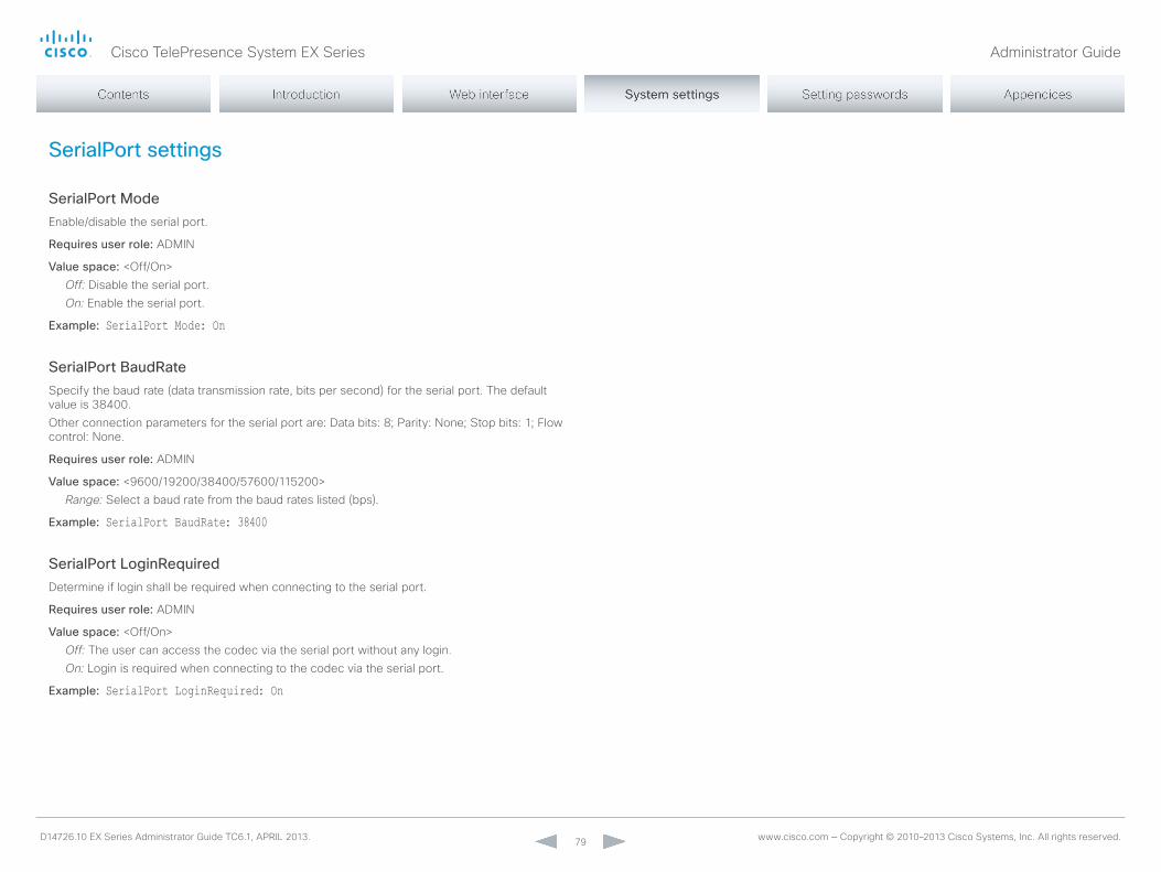
Cisco TelePresence System EX Series Administrator Guide
D14726.10 EX Series Administrator Guide TC6.1, APRIL 2013. www.cisco.com — Copyright © 2010–2013 Cisco Systems, Inc. All rights reserved. 79
SerialPort settings
SerialPort ModeEnable/disable the serial port.
Requires user role: ADmIn
Value space: <off/on>Off: Disable the serial port.On: Enable the serial port.
Example: SerialPort Mode: On
SerialPort BaudRateSpecify the baud rate (data transmission rate, bits per second) for the serial port. The default value is 38400. other connection parameters for the serial port are: Data bits: 8; Parity: none; Stop bits: 1; Flow control: none.
Requires user role: ADmIn
Value space: <9600/19200/38400/57600/115200>Range: Select a baud rate from the baud rates listed (bps).
Example: SerialPort BaudRate: 38400
SerialPort LoginRequiredDetermine if login shall be required when connecting to the serial port.
Requires user role: ADmIn
Value space: <off/on>Off: The user can access the codec via the serial port without any login.On: Login is required when connecting to the codec via the serial port.
Example: SerialPort LoginRequired: On

Cisco TelePresence System EX Series Administrator Guide
D14726.10 EX Series Administrator Guide TC6.1, APRIL 2013. www.cisco.com — Copyright © 2010–2013 Cisco Systems, Inc. All rights reserved. 80
SIP settings
SIP Profile [1..1] URIThe SIP URI or number is used to address the system. This is the URI that is registered and used by the SIP services to route inbound calls to the system. A Uniform Resource Identifier (URI) is a compact string of characters used to identify or name a resource.
Requires user role: ADmIn
Value space: <S: 0, 255>Format: Compact string with a maximum of 255 characters.
Example: SIP Profile 1 URI: "sip:[email protected]"
SIP Profile [1..1] DisplayNameWhen configured the incoming call will report the Displayname instead of the SIP URI.
Requires user role: ADmIn
Value space: <S: 0, 255>Format: String with a maximum of 255 characters.
Example: SIP Profile 1 DisplayName: ""
SIP Profile [1..1] Authentication [1..1] LoginNameThis is the user name part of the credentials used to authenticate towards the SIP proxy.
Requires user role: ADmIn
Value space: <S: 0, 128>Format: String with a maximum of 128 characters.
Example: SIP Profile 1 Authentication 1 LoginName: ""
SIP Profile [1..1] Authentication [1..1] PasswordThis is the password part of the credentials used to authenticate towards the SIP proxy.
Requires user role: ADmIn
Value space: <S: 0, 128>Format: String with a maximum of 128 characters.
Example: SIP Profile 1 Authentication 1 Password: ""
SIP Profile [1..1] DefaultTransportSelect the transport protocol to be used over the LAn.
Requires user role: ADmIn
Value space: <TCP/UDP/Tls/Auto>TCP: The system will always use TCP as the default transport method.UDP: The system will always use UDP as the default transport method.Tls: The system will always use TLS as the default transport method. For TLS connections a SIP CA-list can be uploaded to the video system. If no such CA-list is available on the system then anonymous Diffie Hellman will be used.Auto: The system will try to connect using transport protocols in the following order: TLS, TCP, UDP.
Example: SIP Profile 1 DefaultTransport: Auto
SIP Profile [1..1] TlsVerifyFor TLS connections a SIP CA-list can be uploaded to the video system.
Requires user role: ADmIn
Value space: <off/on>Off: Set to off to allow TLS connections without verifying them. The TLS connections are allowed to be set up without verifying the x.509 certificate received from the server against the local CA-list. This should typically be selected if no SIP CA-list has been uploaded.On: Set to on to verify TLS connections. only TLS connections to servers, whose x.509 certificate is validated against the CA-list, will be allowed.
Example: SIP Profile 1 TlsVerify: Off
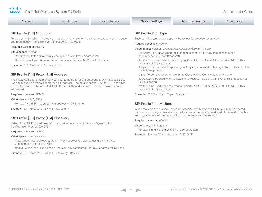
Cisco TelePresence System EX Series Administrator Guide
D14726.10 EX Series Administrator Guide TC6.1, APRIL 2013. www.cisco.com — Copyright © 2010–2013 Cisco Systems, Inc. All rights reserved. 81
SIP Profile [1..1] OutboundTurn on or off the client initiated connections mechanism for firewall traversal, connection reuse and redundancy. The current version supports RFC 5626.
Requires user role: ADmIn
Value space: <off/on>Off: Connect to the single proxy configured first in Proxy Address list.On: Set up multiple outbound connections to servers in the Proxy Address list.
Example: SIP Profile 1 Outbound: Off
SIP Profile [1..1] Proxy [1..4] AddressThe Proxy Address is the manually configured address for the outbound proxy. It is possible to use a fully qualified domain name, or an IP address. The default port is 5060 for TCP and UDP but another one can be provided. If SIP Profile outbound is enabled, multiple proxies can be addressed.
Requires user role: ADmIn
Value space: <S: 0, 255>Format: A valid IPv4 address, IPv6 address or DnS name.
Example: SIP Profile 1 Proxy 1 Address: ""
SIP Profile [1..1] Proxy [1..4] DiscoverySelect if the SIP Proxy address is to be obtained manually or by using Dynamic Host Configuration Protocol (DHCP).
Requires user role: ADmIn
Value space: <Auto/manual>Auto: When Auto is selected, the SIP Proxy address is obtained using Dynamic Host Configuration Protocol (DHCP).Manual: When manual is selected, the manually configured SIP Proxy address will be used.
Example: SIP Profile 1 Proxy 1 Discovery: Manual
SIP Profile [1..1] TypeEnables SIP extensions and special behaviour for a vendor or provider.
Requires user role: ADmIn
Value space: <Standard/Alcatel/Avaya/Cisco/microsoft/nortel>Standard: To be used when registering to standard SIP Proxy (tested with Cisco TelePresence VCS and Broadsoft)Alcatel: To be used when registering to Alcatel-Lucent omniPCX Enterprise. noTE: This mode is not fully supported.Avaya: To be used when registering to Avaya Communication manager. noTE: This mode is not fully supported.Cisco: To be used when registering to Cisco Unified Communication manager.Microsoft: To be used when registering to microsoft LCS or oCS. noTE: This mode is not fully supported.Nortel: To be used when registering to nortel mCS 5100 or mCS 5200 PBX. noTE: This mode is not fully supported.
Example: SIP Profile 1 Type: Standard
SIP Profile [1..1] MailboxWhen registered to a Cisco Unified Communications manager (CUCm) you may be offered the option of having a private voice mailbox. Enter the number (address) of the mailbox in this setting, or leave the string empty if you do not have a voice mailbox.
Requires user role: ADmIn
Value space: <S: 0, 255>>Format: String with a maximum of 255 characters.
Example: SIP Profile 1 Mailbox: "12345678"

Cisco TelePresence System EX Series Administrator Guide
D14726.10 EX Series Administrator Guide TC6.1, APRIL 2013. www.cisco.com — Copyright © 2010–2013 Cisco Systems, Inc. All rights reserved. 82
SIP Profile [1..1] LineWhen registered to a Cisco Unified Communications manager (CUCm) the endpoint may be part of a shared line. This means that several devices share the same directory number. The different devices sharing the same number receive status from the other appearances on the line as defined in RFC 4235.note that shared lines are set up by CUCm, not by the endpoint. Therefore do not change this setting manually; CUCm pushes this information to the endpoint when required.
Requires user role: ADmIn
Value space: <Private/Shared>Shared: The system is part of a shared line and is therefore sharing its directory number with other devices.Private: This system is not part of a shared line (default).
Example: SIP Profile 1 Line: Private
SIP ListenPortTurn on or off the listening for incoming connections on the SIP TCP/UDP ports. If turned off, the endpoint will only be reachable through the SIP registrar (CUCm or VCS). It is recommended to leave this setting at its default value.
Requires user role: ADmIn
Value space: <on/off>On: Listening for incoming connections on the SIP TCP/UDP ports is turned on.Off: Listening for incoming connections on the SIP TCP/UDP ports is turned off.
Example: SIP ListenPort: On
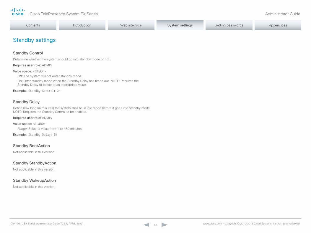
Cisco TelePresence System EX Series Administrator Guide
D14726.10 EX Series Administrator Guide TC6.1, APRIL 2013. www.cisco.com — Copyright © 2010–2013 Cisco Systems, Inc. All rights reserved. 83
Standby settings
Standby ControlDetermine whether the system should go into standby mode or not.
Requires user role: ADmIn
Value space: <off/on>Off: The system will not enter standby mode.On: Enter standby mode when the Standby Delay has timed out. noTE: Requires the Standby Delay to be set to an appropriate value.
Example: Standby Control: On
Standby DelayDefine how long (in minutes) the system shall be in idle mode before it goes into standby mode. noTE: Requires the Standby Control to be enabled.
Requires user role: ADmIn
Value space: <1..480>Range: Select a value from 1 to 480 minutes.
Example: Standby Delay: 10
Standby BootActionnot applicable in this version.
Standby StandbyActionnot applicable in this version.
Standby WakeupActionnot applicable in this version.

Cisco TelePresence System EX Series Administrator Guide
D14726.10 EX Series Administrator Guide TC6.1, APRIL 2013. www.cisco.com — Copyright © 2010–2013 Cisco Systems, Inc. All rights reserved. 84
SystemUnit settings
SystemUnit NameEnter a System name to define a name of the system unit. If the H.323 Alias ID is configured on the system then this ID will be used instead of the system name. The system name will be displayed: 1) When the codec is acting as an SnmP Agent. 2) Towards a DHCP server.
Requires user role: ADmIn
Value space: <S: 0, 50>Format: String with a maximum of 50 characters.
Example: SystemUnit Name: "Meeting Room"
SystemUnit MenuLanguageSelect the language to be used on the Touch controller.
Requires user role: USER
Value space: <English/ChineseSimplified/ChineseTraditional/Czech/Danish/Dutch/Finnish/French/German/Hungarian/Italian/Japanese/Korean/norwegian/Polish/PortugueseBrazilian/Russian/Spanish/Swedish/Turkish>
Example: SystemUnit MenuLanguage: English
SystemUnit ContactInfo TypeChoose which type of contact information to show in the status field in the upper left corner of the Touch controller.
Requires user role: ADmIn
Value space: <Auto/none/IPv4/IPv6/H323Id/E164Alias/H320number/SipUri/Systemname/Displayname>
Auto: Show the address which another system can dial to reach this system. The address depends on the default call protocol and system registration.None: Do not show any contact information in the status field.IPv4: Show the IPv4 address as contact information.IPv6: Show the IPv6 address as contact information.H323Id: Show the H.323 ID as contact information (see the H323 Profile [1..1] H323Alias ID setting).E164Alias: Show the H.323 E164 Alias as contact information (see the H323 Profile [1..1] H323Alias E164 setting).H320Number: Show the H.320 number as contact information (only applicable if connected to a Cisco TelePresence ISDn Link gateway).SipUri: Show the SIP URI as contact information (see the SIP Profile [1..1] URI setting).SystemName: Show the system name as contact information (see the SystemUnit name setting).DisplayName: Show the display name as contact information (see the SIP Profile [1..1] Displayname setting).
Example: SystemUnit ContactInfo Type: Auto
SystemUnit CallLogging ModeSet the call logging mode for calls that are received or placed by the system. The call logs may then be viewed via the web interface.
Requires user role: ADmIn
Value space: <off/on>Off: Disable logging.On: Enable logging.
Example: SystemUnit CallLogging Mode: On

Cisco TelePresence System EX Series Administrator Guide
D14726.10 EX Series Administrator Guide TC6.1, APRIL 2013. www.cisco.com — Copyright © 2010–2013 Cisco Systems, Inc. All rights reserved. 85
SystemUnit IrSensornot fully supported in this software version. Do not change this setting; it is included only for testing.

Cisco TelePresence System EX Series Administrator Guide
D14726.10 EX Series Administrator Guide TC6.1, APRIL 2013. www.cisco.com — Copyright © 2010–2013 Cisco Systems, Inc. All rights reserved. 86
Time settings
Time ZoneSet the time zone where the system is located, using Windows time zone description format.
Requires user role: USER
Value space: <GmT-12:00 (International Date Line West)/GmT-11:00 (midway Island, Samoa)/GmT-10:00 (Hawaii)/GmT-09:00 (Alaska)/GmT-08:00 (Pacific Time (US & Canada); Tijuana)/GmT-07:00 (Arizona)/GmT-07:00 (mountain Time (US & Canada))/GmT-07:00 (Chihuahua, La Paz, mazatlan)/GmT-06:00 (Central America)/GmT-06:00 (Saskatchewan)/GmT-06:00 (Guadalajara, mexico City, monterrey)/GmT-06:00 (Central Time (US & Canada))/GmT-05:00 (Indiana (East))/GmT-05:00 (Bogota, Lima, Quito)/GmT-05:00 (Eastern Time (US & Canada))/GmT-04:30 (Caracas)/GmT-04:00 (La Paz)/GmT-04:00 (Santiago)/GmT-04:00 (Atlantic Time (Canada))/GmT-03:30 (newfoundland)/GmT-03:00 (Buenos Aires, Georgetown)/GmT-03:00 (Greenland)/GmT-03:00 (Brasilia)/GmT-02:00 (mid-Atlantic)/GmT-01:00 (Cape Verde Is.)/GmT-01:00 (Azores)/GmT (Casablanca, monrovia)/GmT (Coordinated Universal Time)/GmT (Greenwich mean Time : Dublin, Edinburgh, Lisbon, London)/GmT+01:00 (West Central Africa)/GmT+01:00 (Amsterdam, Berlin, Bern, Rome, Stockholm, Vienna)/GmT+01:00 (Brussels, Copenhagen, madrid, Paris)/GmT+01:00 (Sarajevo, Skopje, Warsaw, Zagreb)/GmT+01:00 (Belgrade, Bratislava, Budapest, Ljubljana, Prague)/GmT+02:00 (Harare, Pretoria)/GmT+02:00 (Jerusalem)/GmT+02:00 (Athens, Istanbul, minsk)/GmT+02:00 (Helsinki, Kyiv, Riga, Sofia, Tallinn, Vilnius)/GmT+02:00 (Cairo)/GmT+02:00 (Bucharest)/GmT+03:00 (nairobi)/GmT+03:00 (Kuwait, Riyadh)/GmT+03:00 (moscow, St. Petersburg, Volgograd)/GmT+03:00 (Baghdad)/GmT+03:30 (Tehran)/GmT+04:00 (Abu Dhabi, muscat)/GmT+04:00 (Baku, Tbilisi, yerevan)/GmT+04:30 (Kabul)/GmT+05:00 (Islamabad, Karachi, Tashkent)/GmT+05:00 (Ekaterinburg)/GmT+05:30 (Chennai, Kolkata, mumbai, new Delhi)/GmT+05:45 (Kathmandu)/GmT+06:00 (Sri Jayawardenepura)/GmT+06:00 (Astana, Dhaka)/GmT+06:00 (Almaty, novosibirsk)/GmT+06:30 (Rangoon)/GmT+07:00 (Bangkok, Hanoi, Jakarta)/GmT+07:00 (Krasnoyarsk)/GmT+08:00 (Perth)/GmT+08:00 (Taipei)/GmT+08:00 (Kuala Lumpur, Singapore)/GmT+08:00 (Beijing, Chongqing, Hong Kong, Urumqi)/GmT+08:00 (Irkutsk, Ulaan Bataar)/GmT+09:00 (osaka, Sapporo, Tokyo)/GmT+09:00 (Seoul)/GmT+09:00 (yakutsk)/GmT+09:30 (Darwin)/GmT+09:30 (Adelaide)/GmT+10:00 (Guam, Port moresby)/GmT+10:00 (Brisbane)/GmT+10:00 (Vladivostok)/GmT+10:00 (Hobart)/GmT+10:00 (Canberra, melbourne, Sydney)/GmT+11:00 (magadan, Solomon Is., new Caledonia)/GmT+12:00 (Fiji, Kamchatka, marshall Is.)/GmT+12:00 (Auckland, Wellington)/GmT+13:00 (nuku alofa)>
Range: Select a time zone from the list time zones. If using a command line interface; watch up for typos.
Example: Time Zone: "GMT (Greenwich Mean Time : Dublin, Edinburgh, Lisbon, London)"
Time TimeFormatSet the time format.
Requires user role: USER
Value space: <24H/12H>24H: Set the time format to 24 hours.12H: Set the time format to 12 hours (Am/Pm).
Example: Time TimeFormat: 24H
Time DateFormatSet the date format.
Requires user role: USER
Value space: <DD_mm_yy/mm_DD_yy/yy_mm_DD>DD_MM_YY: The date January 30th 2010 will be displayed: 30.01.10MM_DD_YY: The date January 30th 2010 will be displayed: 01.30.10YY_MM_DD: The date January 30th 2010 will be displayed: 10.01.30
Example: Time DateFormat: DD _ MM _ YY
Cisco TelePresence System EX Series Administrator Guide
D14726.10 EX Series Administrator Guide TC6.1, APRIL 2013. www.cisco.com — Copyright © 2010–2013 Cisco Systems, Inc. All rights reserved. 87
UserInterface settings
UserInterface TouchPanel DefaultPanelSelect whether to display the list of contacts, the list of scheduled meetings, or a dial pad on the Touch controller as default.
Requires user role: USER
Value space: <ContactList/meetingList/Dialpad>ContactList: The contact list (favorites, directory and history) will appear as default on the Touch controller. MeetingList: The list of scheduled meetings will appear as default on the Touch controller.Dialpad: A dial pad will appear as default on the Touch controller.
Example: UserInterface TouchPanel DefaultPanel: ContactList
Cisco TelePresence System EX Series Administrator Guide
D14726.10 EX Series Administrator Guide TC6.1, APRIL 2013. www.cisco.com — Copyright © 2010–2013 Cisco Systems, Inc. All rights reserved. 88
Video settings
Video Input Source [1..3]/[1..2] NamenoTE: EX90 has Video Input Source [1..3] and EX60 has Video Input Source [1..2].Enter a name for the video input source.
Requires user role: ADmIn
Value space: <S: 0, 50>Format: String with a maximum of 50 characters.
Example: Video Input Source 1 Name: ""
Video Input Source [1] ConnectorSelect which video input connector to be active on video input source 1.
Requires user role: ADmIn
Value space: <HDmI>/<DVI>HDMI (EX90): Select HDmI when you want to use the HDmI as the video input source 1. DVI (EX60): Select DVI when you want to use the DVI as the video input source 1.
Example: Video Input Source 1 Connector: HDMI
Video Input Source [2] ConnectorSelect which video input connector to be active on video input source 2.
Requires user role: ADmIn
Value space: <DVI>/<CAmERA>DVI (EX90): Select DVI when you want to use the DVI-I as input source 2.CAMERA (EX60): Select CAmERA when you want to use the camera as input source 2.
Example: Video Input Source 2 Connector: DVI
Video Input Source [3] ConnectornoTE: Applies only to EX90.Select which video input connector to be active on video input source 3.
Requires user role: ADmIn
Value space: <CAmERA>CAMERA: Select CAmERA when you want to use the camera as input source 3.
Example: Video Input Source 3 Connector: CAMERA
Video Input Source [1..3]/[1..2] TypenoTE: EX90 has Video Input Source [1..3] and EX60 has Video Input Source [1..2].Set which type of input source is connected to the video input.
Requires user role: ADmIn
Value space: <other/camera/PC/DVD/document_camera>Other: Select other when some other type of equipment is connected to the selected video input.Camera: Select Camera when you have a camera connected to the selected video input.PC: Select PC when you have a PC connected to the selected video input.DVD: Select DVD when you have a DVD player connected to the selected video input.Document_Camera: Select Document_Camera when you have a document camera connected to the selected video input.
Example: Video Input Source 1 Type: PC

Cisco TelePresence System EX Series Administrator Guide
D14726.10 EX Series Administrator Guide TC6.1, APRIL 2013. www.cisco.com — Copyright © 2010–2013 Cisco Systems, Inc. All rights reserved. 89
Video Input Source [1..3]/[1..2] PresentationSelectionIn general, any input source can be used as a presentation source; normally, the main camera (self view) will not be used as a presentation source.This setting is used to define whether to display the presentation source on the local video system's display automatically or not. To share the presentation with the far end always requires additional action (tap Start Presenting on the Touch controller).EX60: The value for Source 1 is fixed to Automatic. The default value for Source 2 (camera) is Hidden.EX90: The values for Source 1 and Source 2 are fixed to Automatic. The default value for Source 3 (camera) is Hidden.
Requires user role: ADmIn
Value space: <manual/Automatic/Hidden>Manual: The content on the input source will not be presented on the local video system's display before you select it. Use the Touch controller to choose which input source to present.Automatic: Any content on the input source will be presented on the local video system's display automatically. If there is active content on more than one input source (which is set to Automatic) the most recent one will be used. Hidden: The input source is not expected to be used as a presentation source.
Example: Video Input Source 1 PresentationSelection: Automatic
Video Input Source [1..3]/[1..2] CameraControl ModeIndicates whether or not camera control is enabled for the selected video input source when the video input is active. In this product this value is fixed for all input sources.
Value space: <off/on>Off: Disable camera control.On: Enable camera control.
Video Input Source [1..3]/[1..2] CameraControl CameraIdIndicates the ID of the camera. This value is fixed in this product.
Value space: <1>Range: Indicates the ID of the camera.
Video Input Source [1..3]/[1..2] OptimalDefinition ProfilenoTE: EX90 has Video Input Source [1..3] and EX60 has Video Input Source [1..2].The Video Input Source Quality setting must be set to motion for the optimal definition settings to take any effect. The optimal definition profile should reflect the lighting conditions in your room and the quality of the video input (camera); the better the lighting conditions and video input, the higher the profile. Then, in good lighting conditions, the video encoder will provide better quality (higher resolution or frame rate) for a given call rate.Generally, we recommend using the normal or medium profiles. However, when the lighting conditions are good, the High profile can be set in order to increase the resolution for a given call rate.Some typical resolutions used for different optimal definition profiles, call rates and transmit frame rates are shown in the table below. It is assumed that dual video is not used. The resolution must be supported by both the calling and called systems. Use the Video Input Source optimalDefinition Threshold60fps setting to decide when to use the 60 fps frame rate. In order to allow a transmit frame rate of 60 fps, you must enable 60 Hz capture frequency on the camera with the Cameras Camera 1 FrameRate setting.
.
Requires user role: ADmIn
Value space: <normal/medium/High>Normal: Use this profile for a normally to poorly lit environment. Resolutions will be set rather conservative.Medium: Requires good and stable lighting conditions and a good quality video input. For some call rates this leads to higher resolution.High: Requires nearly optimal video conferencing lighting conditions and a good quality video input in order to achieve a good overall experience. Rather high resolutions will be used.
Example: Video Input Source 2 OptimalDefinition Profile: Normal
Typical resolutions used for different optimal definition profiles, call rates and frame rates
Frame rate
Optimal Definition
Profile
Call rate
256 kbps 768 kbps 1152 kbps 1472 kbps 2560 kbps 4 Mbps 6 Mbps
30 fps
Normal 512 × 288 1024 × 576 1280 × 720 1280 × 720 1920 × 1080 1920 × 1080 1920 × 1080
Medium 640 × 360 1280 × 720 1280 × 720 1280 × 720 1920 × 1080 1920 × 1080 1920 × 1080
High 768 × 448 1280 × 720 1280 × 720 1920 × 1080 1920 × 1080 1920 × 1080 1920 × 1080
60 fps
Normal 256 × 144 512 × 288 768 × 448 1024 × 576 1280 × 720 1280 × 720 1280 × 720
Medium 256 × 144 768 × 448 1024 × 576 1024 × 576 1280 × 720 1280 × 720 1280 × 720
High 512 × 288 1024 × 576 1280 × 720 1280 × 720 1280 × 720 1280 × 720 1280 × 720
Cisco TelePresence System EX Series Administrator Guide
D14726.10 EX Series Administrator Guide TC6.1, APRIL 2013. www.cisco.com — Copyright © 2010–2013 Cisco Systems, Inc. All rights reserved. 90
Video Input Source [1..3]/[1..2] OptimalDefinition Threshold60fpsnoTE: EX90 has Video Input Source [1..3] and EX60 has Video Input Source [1..2].For each video input, this setting tells the system the lowest resolution where it should transmit 60 fps. So for all resolutions lower than this, the maximum transmitted frame rate would be 30 fps, while above this resolution 60 fps will also be possible, if the available bandwidth is adequate.In order to allow a transmit frame rate of 60 fps, you must enable 60 Hz capture frequency on the camera with the Cameras Camera 1 FrameRate setting.
Requires user role: ADmIn
Value space: <512_288/768_448/1024_576/1280_720/1920_1080/never>512_288: Set the threshold to 512x288.768_448: Set the threshold to 768x448.1024_576: Set the threshold to 1024x576.1280_720: Set the threshold to 1280x720.1920_1080: Set the threshold to 1920x1080.Never: Do not set a threshold for transmitting 60fps.
Example: Video Input Source 2 OptimalDefinition Threshold60fps: 1280 _ 720
Video Input Source [1..3]/[1..2] QualitynoTE: EX90 has Video Input Source [1..3] and EX60 has Video Input Source [1..2].When encoding and transmitting video there will be a trade-off between high resolution and high framerate. For some video sources it is more important to transmit high framerate than high resolution and vice versa. The Quality setting specifies whether to give priority to high frame rate or to high resolution for a given source.
Requires user role: ADmIn
Value space: <motion/Sharpness>Motion: Gives the highest possible framerate. Used when there is a need for higher frame rates, typically when a large number of participants are present or when there is a lot of motion in the picture.Sharpness: Gives the highest possible resolution. Used when you want the highest quality of detailed images and graphics.
Example: Video Input Source 2 Quality: Motion
Video MainVideoSourceDefine which video input source shall be used as the main video source. The video input source is configured with the "Video Input Source [1..n] Connector" setting.
Requires user role: USER
Value space: <1/2/3>/<1/2>Range: Select the source to be used as the main video source.
Example: Video MainVideoSource: 3
Video DefaultPresentationSourcenot applicable in this version.
Range: Select the video source to be used as the presentation source.
Video Input HDMI [1..1] RGBQuantizationRangenoTE: Applies only to EX90.All devices with HDmI inputs should follow the rules for RGB video quantization range defined in CEA-861. Unfortunately some devices do not follow the standard and this configuration may be used to override the settings to get a perfect image with any source.
Requires user role: ADmIn
Value space: <Auto/Full/Limited>Auto: RGB quantization range is automatically selected based on the RGB Quantization Range bits (Q0, Q1) in the AVI infoframe. If no AVI infoframe is available, RGB quantization range is selected based on video format according to CEA-861-E.Full: Full quantization range. The R, G, B quantization range includes all code values (0 - 255). This is defined in CEA-861-E.Limited: Limited Quantization Range. R, G, B quantization range that excludes some code values at the extremes (16 - 235). This is defined in CEA-861-E.
Example: Video Input 1 HDMI 1 RGBQuantizationRange: Auto

Cisco TelePresence System EX Series Administrator Guide
D14726.10 EX Series Administrator Guide TC6.1, APRIL 2013. www.cisco.com — Copyright © 2010–2013 Cisco Systems, Inc. All rights reserved. 91
Video Input DVI [2]/[1] RGBQuantizationRangenoTE: EX90 has the DVI 2 input connector and EX60 has the DVI 1 input connector.All devices with DVI inputs should follow the rules for RGB video quantization range defined in CEA-861. Unfortunately some devices do not follow the standard and this configuration may be used to override the settings to get a perfect image with any source. The default value is set to Full because most DVI sources expects full quantization range.
Requires user role: ADmIn
Value space: <Auto/Full/Limited>Auto: RGB quantization range is automatically selected based on video format according to CEA-861-E. CE video formats will use limited quantization range levels. IT video formats will use full quantization range levels.Full: Full quantization range. The R, G, B quantization range includes all code values (0 - 255). This is defined in CEA-861-E.Limited: Limited Quantization Range. R, G, B quantization range that excludes some code values at the extremes (16 - 235). This is defined in CEA-861-E.
Example: Video Input 1 DVI 2 RGBQuantizationRange: Full
Video Input DVI [2]/[1] TypenoTE: EX90 has the DVI 2 input connector and EX60 has the DVI 1 input connector.The official DVI standard supports both digital and analog signals. In most cases the default AutoDetect setting can detect whether the signal is analog RGB or digital. However, in some rare cases when DVI-I cables are used (these cables can carry both the analog and digital signals) the auto detection fails. This setting makes it possible to override the AutoDetect and select the correct DVI video input.
Requires user role: ADmIn
Value space: <AutoDetect/Digital/AnalogRGB/AnalogyPbPr>AutoDetect: Set to AutoDetect to automatically detect if the signal is analog RGB or digital. Digital: Set to Digital to force the DVI video input to Digital when using DVI-I cables with both analog and digital pins and AutoDetect fails. AnalogRGB: Set to AnalogRGB to force the DVI video input to AnalogRGB when using DVI-I cables with both analog and digital pins and AutoDetect fails. AnalogYPbPr: Set to AnalogyPbPr to force the DVI video input to AnalogyPbPr, as the component (yPbPr) signal cannot be auto detected.
Example: Video Input DVI 2 Type: AutoDetect
Video ControlPanel BrightnessSet the brightness level for the Touch controller.
Requires user role: ADmIn
Value space: <0..100>Range: Select a value from 0 to 100.
Example: Video ControlPanel Brightness: 100
Video Layout ScalingDefine how the system shall adjust the aspect ratio for images or frames when there is a difference between the image and the frame it is to be placed in.
Requires user role: ADmIn
Value space: <off/on>Off: no adjustment of the aspect ratio.On: Let the system automatically adjust aspect ratio.
Example: Video Layout Scaling: On
Video Layout ScaleToFrameDefine what to do if the aspect ratio of a video input source doesn't match the aspect ratio of the corresponding image frame in a composition. For example if you have a 4:3 input source (like XGA) to be displayed on a 16:9 output (like HD720).
Requires user role: ADmIn
Value space: <manual/maintainAspectRatio/StretchToFit>Manual: If the difference in aspect ratio between the video input source and the target image frame is less than the Video Layout ScaleToFrameThreshold setting (in percent), the image is stretched to fit. If not, the system will maintain the original aspect ratio.MaintainAspectRatio: maintain the aspect ratio of the input source, and fill in black in the rest of the frame (letter boxing or pillar boxing).StretchToFit: Stretch (horizontally or vertically) the input source to fit into the image frame. noTE: The general limitation is that you cannot upscale in one direction and at the same time downscale in the other direction. In such situations the codec will apply letterboxing.
Example: Video Layout ScaleToFrame: MaintainAspectRatio

Cisco TelePresence System EX Series Administrator Guide
D14726.10 EX Series Administrator Guide TC6.1, APRIL 2013. www.cisco.com — Copyright © 2010–2013 Cisco Systems, Inc. All rights reserved. 92
Video Layout ScaleToFrameThresholdonly applicable if the Video Layout ScaleToFrame setting is set to manual. If the difference in aspect ratio between the video input source and the target image frame is less than the ScaleToFrameThreshold setting (in percent), the image is stretched to fit. If not, the system will maintain the original aspect ratio.
Requires user role: ADmIn
Value space: <0..100>Range: Select a value from 0 to 100 percent.
Example: Video Layout ScaleToFrameThreshold: 5
Video SelfviewDetermine if the main video source (self view) shall be displayed on screen.This setting is obsoleted by the Video SelfviewDefault mode setting as from TC6.0.
Requires user role: USER
Value space: <off/on>Off: Do not display self view on screen.On: Display self view on screen.
Example: Video Selfview: On
Video SelfviewControl AutoResizingThe size of the self view frame can be configured to automatically change according to the following rules. The size is reduced from full screen to PiP (picture-in-picture) when there is a change in a frame that overlaps with the self view frame. The size is increased from PiP to full screen when nothing else is displayed on the monitor. The last rule does not apply to monitors with monitorRole set to First.
Requires user role: ADmIn
Value space: <off/on>Off: Self view will not be automatically resized.On: Self view is automatically resized as described above.
Example: Video SelfviewControl AutoResizing: On
Video SelfviewDefault ModeDetermine if the main video source (self view) shall be displayed on screen after a call. The position and size of the self view window is determined by the Video SelfviewDefault PIPPosition and the Video Selfview Fullscreenmode settings respectively.This setting obsoletes the Video Selfview setting as from TC6.0.
Requires user role: ADmIn
Value space: <off/Current/on>Off: Self view is switched off when leaving a call.Current: Self view is left as is, i.e. if it was on during the call, it remains on after the call; if it was off during the call, it remains off after the call.On: Self view is switched on when leaving a call.
Example: Video SelfviewDefault Mode: Current
Video SelfviewDefault FullscreenModeDetermine if the main video source (self view) shall be shown in full screen or as a small picture-in-picture (PiP) after a call. The setting only takes effect when self view is switched on (see the Video SelfviewDefault mode setting).
Requires user role: ADmIn
Value space: <off/Current/on>Off: Self view will be shown as a PiP.Current: The size of the self view picture will be kept unchanged when leaving a call, i.e. if it was a PiP during the call, it remains a PiP after the call; if it was fullscreen during the call, it remains fullscreen after the call.On: The self view picture will be shown in fullscreen.
Example: Video SelfviewDefault FullscreenMode: Current

Cisco TelePresence System EX Series Administrator Guide
D14726.10 EX Series Administrator Guide TC6.1, APRIL 2013. www.cisco.com — Copyright © 2010–2013 Cisco Systems, Inc. All rights reserved. 93
Video SelfviewDefault PIPPositionDetermine the position on screen of the small self view picture-in-picture (PiP) after a call. The setting only takes effect when self view is switched on (see the Video SelfviewDefault mode setting) and fullscreen view is switched off (see the Video SelfviewDefault Fullscreenmode setting).
Requires user role: ADmIn
Value space: <Current/UpperLeft/UpperCenter/UpperRight/CenterLeft/CenterRight/LowerLeft/LowerRight >
Current: The position of the self view PiP will be kept unchanged when leaving a call.UpperLeft: The self view PiP will appear in the upper left corner of the screen.UpperCenter: The self view PiP will appear in the upper center position.UpperRight: The self view PiP will appear in the upper right corner of the screen.CenterLeft: The self view PiP will appear in the center left position.CentreRight: The self view PiP will appear in the center right position.LowerLeft: The self view PiP will appear in the lower left corner of the screen.LowerRight: The self view PiP will appear in the lower right corner of the screen.
Example: Video SelfviewDefault PIPPosition: Current
Video SelfviewDefault OnMonitorRoleDetermine which monitor/output to display the main video source (self view) on after a call. The value reflects the monitor roles set for the different outputs in the Video output HDmI/Internal monitorRole settings.The setting applies both when self view is displayed in full screen, and when it is displayed as picture-in-picture (PiP), but only if the Video monitors setting is set to Dual.
Requires user role: ADmIn
Value space: <First/Second/Current>First: The self view picture will be shown on outputs with the Video output LCD/Internal monitorRole set to First.Second: The self view picture will be shown on outputs with the Video output LCD/Internal monitorRole set to Second.Current: When leaving the call, the self view picture will be kept on the same output as during the call.
Example: Video SelfviewDefault OnMonitorRole: Current
Video CamCtrlPip CallSetup ModeThis setting is used to switch on self view for a short while when setting up a call. The Video CamCtrlPip CallSetup Duration setting determines for how long it remains on. This applies when self view in general is switched off.
Requires user role: ADmIn
Value space: <off/on>Off: Self view is not shown automatically during call setup.On: Self view is shown automatically during call setup.
Example: Video CamCtrlPip CallSetup Mode: Off
Video CamCtrlPip CallSetup DurationThis setting only has an effect when the Video CamCtrlPip CallSetup mode setting is switched on. In this case, the number of seconds set here determines for how long self view is shown before it is automatically switched off.
Requires user role: ADmIn
Value space: <1..60>Range: Choose for how long self view remains on. The valid range is between 1 and 60 seconds.
Example: Video CamCtrlPip CallSetup Duration: 10

Cisco TelePresence System EX Series Administrator Guide
D14726.10 EX Series Administrator Guide TC6.1, APRIL 2013. www.cisco.com — Copyright © 2010–2013 Cisco Systems, Inc. All rights reserved. 94
Video PIP ActiveSpeaker DefaultValue PositionDetermine the position on screen of the active speaker picture-in-picture (PiP). The setting only takes effect when using a video layout where the active speaker is a PiP, i.e. the overlay layout, or possibly a Custom layout (see the Video Layout LocalLayoutFamily setting). The setting takes effect from the next call onwards; if changed during a call, it will have no effect on the current call.
Requires user role: ADmIn
Value space: <Current/UpperLeft/UpperCenter/UpperRight/CenterLeft/CenterRight/LowerLeft/LowerRight>
Current: The position of the active speaker PiP will be kept unchanged when leaving a call.UpperLeft: The active speaker PiP will appear in the upper left corner of the screen.UpperCenter: The active speaker PiP will appear in the upper center position.UpperRight: The active speaker PiP will appear in the upper right corner of the screen.CenterLeft: The active speaker PiP will appear in the center left position.CentreRight: The active speaker PiP will appear in the center right position.LowerLeft: The active speaker PiP will appear in the lower left corner of the screen.LowerRight: The active speaker PiP will appear in the lower right corner of the screen.
Example: Video PIP ActiveSpeaker DefaultValue Position: Current
Video PIP Presentation DefaultValue PositionDetermine the position on screen of the presentation picture-in-picture (PiP). The setting only takes effect when the presentation is explicitly minimized to a PiP, for example using the Touch controller. The setting takes effect from the next call onwards; if changed during a call, it will have no effect on the current call.
Requires user role: ADmIn
Value space: <Current/UpperLeft/UpperCenter/UpperRight/CenterLeft/CenterRight/LowerLeft/LowerRight >
Current: The position of the presentation PiP will be kept unchanged when leaving a call.UpperLeft: The presentation PiP will appear in the upper left corner of the screen.UpperCenter: The presentation PiP will appear in the upper center position.UpperRight: The presentation PiP will appear in the upper right corner of the screen.CenterLeft: The presentation PiP will appear in the center left position.CentreRight: The presentation PiP will appear in the center right position.LowerLeft: The presentation PiP will appear in the lower left corner of the screen.LowerRight: The presentation PiP will appear in the lower right corner of the screen.
Example: Video PIP Presentation DefaultValue Position: Current
Video Layout LocalLayoutFamilySelect which video layout family to use locally.
Requires user role: ADmIn
Value space: <Auto/FullScreen/Equal/PresentationSmallSpeaker/PresentationLargeSpeaker/Prominent/overlay/Single>
Auto: The default layout family, as given in the layout database provided by the system, will be used as the local layout. FullScreen: The FullScreen layout family will be used as the local layout. It means that the active speaker or presentation will be shown in full screen. Using this value is not recommended as from TC6.0.Equal: The Equal layout family will be used as the local layout. All videos have equal size, as long as there is space enough on the screen. PresentationSmallSpeaker: The PresentationSmallSpeaker layout family will be used as the local layout. Using this value is not recommended as from TC6.0.PresentationLargeSpeaker: The PresentationLargeSpeaker layout family will be used as the local layout. Using this value is not recommended as from TC6.0.Prominent: The Prominent layout family will be used as the local layout. The active speaker, or the presentation if present, will be a large picture, while the other participants will be small pictures. Transitions between active speakers are voice switched.Overlay: The overlay layout family will be used as the local layout. The active speaker, or the presentation if present, will be shown in full screen, while the other participants will be small pictures-in-picture (PiP). Transitions between active speakers are voice switched.Single: The active speaker, or the presentation if present, will be shown in full screen. The other participants are not shown. Transitions between active speakers are voice switched.
Example: Video Layout LocalLayoutFamily: Auto
Cisco TelePresence System EX Series Administrator Guide
D14726.10 EX Series Administrator Guide TC6.1, APRIL 2013. www.cisco.com — Copyright © 2010–2013 Cisco Systems, Inc. All rights reserved. 95
Video Layout RemoteLayoutFamilySelect which video layout family to be used for the remote participants.
Requires user role: ADmIn
Value space: <Auto/FullScreen/Equal/PresentationSmallSpeaker/PresentationLargeSpeaker/Prominent/overlay/Single>
Auto: The default layout family, as given by the local layout database, will be used as the remote layout. FullScreen: The FullScreen layout family will be used as the remote layout. It means that the active speaker or presentation will be shown in full screen. It is recommended not to use this value as from TC6.0.Equal: The Equal layout family will be used as the remote layout. All videos have equal size, as long as there is space enough on the screen.PresentationSmallSpeaker: The PresentationSmallSpeaker layout family will be used as the remote layout. Using this value is not recommended as from TC6.0.PresentationLargeSpeaker: The PresentationLargeSpeaker layout family will be used as the remote layout. Using this value is not recommended as from TC6.0.Prominent: The Prominent layout family will be used as the remote layout. The active speaker, or the presentation if present, will be a large picture, while the other participants will be small pictures. Transitions between active speakers are voice switched.Overlay: The overlay layout family will be used as the remote layout. The active speaker, or the presentation if present, will be shown in full screen, while the other participants will be small pictures-in-picture (PiP). Transitions between active speakers are voice switched.Single: The active speaker, or the presentation if present, will be shown in full screen. The other participants are not shown. Transitions between active speakers are voice switched.
Example: Video Layout RemoteLayoutFamily: Auto
Video MonitorsSet the monitor layout mode.
Requires user role: ADmIn
Value space: <Single/DualPresentationonly>Single: The same layout is shown on all monitors.DualPresentationOnly: All participants in the call will be shown on the first monitor, while the presentation (if any) will be shown on the second monitor. This value is not supported on EX60.
Example: Video Monitors: Single
Video OSD Modenot applicable in this version.
Video OSD MenuStartupModenot applicable in this version.
Video OSD VirtualKeyboardnot applicable in this version.
Video OSD EncryptionIndicatorDefine for how long the encryption indicator (a padlock) will be shown on screen. The setting applies to both encrypted and non-encrypted calls, i.e. both to secure and non-secure conferences. The icon for encrypted calls is a locked padlock, and the icon for non-encrypted calls is a crossed out locked padlock.
Requires user role: ADmIn
Value space: <Auto/Alwayson/Alwaysoff>Auto: If the Conference Encryption mode setting is set to BestEffort and the call is encrypted, the encryption indicator is shown during the first seconds of a call. If the Conference Encryption mode setting is set to BestEffort and the call is non-encrypted, the crossed out encryption indicator is shown during the entire call. If the Conference Encryption mode setting is noT set to BestEffort, the encryption indicator is not shown at all.AlwaysOn: The encryption indicator is displayed on screen during the entire call. This applies to both encrypted and non-encrypted calls for all Conference Encryption mode settings.AlwaysOff: The encryption indicator is never displayed on screen. This applies to both encrypted and non-encrypted calls for all Conference Encryption mode settings.
Example: Video OSD EncryptionIndicator: Auto
Video OSD MissedCallsNotificationnot applicable in this version.
Video OSD AutoSelectPresentationSourcenot applicable in this version.

Cisco TelePresence System EX Series Administrator Guide
D14726.10 EX Series Administrator Guide TC6.1, APRIL 2013. www.cisco.com — Copyright © 2010–2013 Cisco Systems, Inc. All rights reserved. 96
Video OSD TodaysBookingsnot applicable in this version.
Video OSD MyContactsExpandednot applicable in this version.
Video OSD Outputnot applicable in this version.
Video OSD InputMethod InputLanguagenot applicable in this version.
Video OSD InputMethod Cyrillicnot applicable in this version.
Video OSD LoginRequirednot applicable in this version.
Video AllowWebSnapshotsAllow or disallow snapshots being taken of the local input sources, remote sites and presentation channel. If allowed, the web interface Call Control page will show snapshots both when idle and in a call.noTE: This feature is disabled by default, and must be enabled from the Touch controller.
Requires user role: ADmIn
Value space: <off/on>Off: Capturing web snapshots is not allowed.On: Web snapshots can be captured and displayed on the web interface.
Example: Video AllowWebSnapshots: Off
Video Output HDMI [1] RGBQuantizationRangenoTE: Applies only to EX90.All devices with HDmI outputs should follow the rules for RGB video quantization range defined in CEA-861. Unfortunately some devices do not follow the standard and this configuration may be used to override the settings to get a perfect image with any display. The default value is set to Full because most HDmI displays expects full quantization range.
Requires user role: ADmIn
Value space: <Auto/Full/Limited>Auto: RGB quantization range is automatically selected based on the RGB Quantization Range bits (Q0, Q1) in the AVI infoframe. If no AVI infoframe is available, RGB quantization range is selected based on video format according to CEA-861-E.Full: Full quantization range. The R, G, B quantization range includes all code values (0 - 255). This is defined in CEA-861-E.Limited: Limited Quantization Range. R, G, B quantization range that excludes some code values at the extremes (16 - 235). This is defined in CEA-861-E.
Example: Video Output HDMI 1 RGBQuantizationRange: Full
Video Output HDMI [1] CEC ModenoTE: Applies only to EX90.The HDmI outputs support Consumer Electronics Control (CEC). When set to on (default is off), and the monitor connected to the HDmI output is CEC compatible and CEC is configured, the system will use CEC to set the monitor in standby when the system enters standby. Likewise the system will wake up the monitor when the system wakes up from standby. Please note that the different manufacturers uses different marketing names for CEC, for example Anynet+ (Samsung); Aquos Link (Sharp); BRAVIA Sync (Sony); HDmI-CEC (Hitachi); Kuro Link (Pioneer); CE-Link and Regza Link (Toshiba); RIHD (onkyo); HDAVI Control, EZ-Sync, VIERA Link (Panasonic); EasyLink (Philips); and netCommand for HDmI (mitsubishi).
Requires user role: ADmIn
Value space: <off/on>Off: Disable CEC control.On: Enable CEC control.
Example: Video Output HDMI 1 CEC Mode: Off

Cisco TelePresence System EX Series Administrator Guide
D14726.10 EX Series Administrator Guide TC6.1, APRIL 2013. www.cisco.com — Copyright © 2010–2013 Cisco Systems, Inc. All rights reserved. 97
Video Output HDMI [1] MonitorRolenoTE: Applies only to EX90, and only when the Dual Display option is installed.Define which video stream to show on the monitor connected to the HDmI output connector. Do not change this setting manually; keep the default setting.
Value space: <Second>Second: Show the presentation, if present, on the monitor connected to the HDmI output.
Video Output HDMI [1] OverscanLevelnoTE: Applies only to EX90.Some TVs or other monitors may not display the whole image sent out on the systems video output, but cuts the outer parts of the image. In this case this setting can be used to let the system not use the outer parts of video resolution. The video will be scaled in this case.
Requires user role: ADmIn
Value space: <medium/High/none>Medium: The system will not use the outer 3% of the output resolution.High: The system will not use the outer 6% of the output resolutionNone: The system will use all of the output resolution.
Example: Video Output HDMI 1 OverscanLevel: None
Video Output HDMI [1] ResolutionnoTE: Applies only to EX90.Select the preferred resolution for the monitor connected to the video output HDmI connector. This will force the resolution on the monitor.
Requires user role: ADmIn
Value space: <Auto/640_480_60/800_600_60/1024_768_60/1280_1024_60/1280_720_50/1280_720_60/1920_1080_50/1920_1080_60/1280_768_60/1360_768_60/1366_768_60/1600_1200_60/1680_1050_60/1920_1200_60>
Auto: The system will automatically try to set the optimal resolution based on negotiation with the connected monitor.Range: 640x480@60p, 800x600@60p, 1024x768@60p, 1280x1024@60p, 1280x720@50p, 1280x720@60p, 1920x1080@50p, 1920x1080@60p, 1280x768@60p, 1360x768@60p, 1366x768@60p, 1600x1200@60p, 1680x1050@60p, 1920x1200@60p
Example: Video Output HDMI 1 Resolution: Auto
Video Output LCD [2]/[1] ResolutionnoTE: EX90 has the LCD 2 connector and EX60 has the LCD 1 connector.Set the screen resolution.
Requires user role: ADmIn
Value space: EX90: <1920_1200_60> EX60: <1920_1080_60>Range: The screen resolution is 1920 x 1200 60 Hz for EX90 and 1920 x 1080 60 Hz for EX60.
Example: Video Output LCD 1 Resolution: 1920 _ 1080 _ 60
Video Output LCD [2]/[1] MonitorRolenoTE: EX90 has the LCD 2 connector and EX60 has the LCD 1 connector.Set the LCD monitor role. Do not change this setting manually; keep the default setting.
Value space: <InternalSetup>InternalSetup: The internal setup as defined by the Touch controller will be used.
Video Output LCD [2]/[1] BrightnessnoTE: EX90 has the LCD 2 connector and EX60 has the LCD 1 connector.Set the brightness level for the monitor.
Requires user role: ADmIn
Value space: <0..100>Range: Select a value from 0 to 100.
Example: Video Output LCD 1 Brightness: 50
Video Output LCD [2]/[1] RednoTE: EX90 has the LCD 2 connector and EX60 has the LCD 1 connector.Set the Red color level for the monitor.
Requires user role: ADmIn
Value space: <0..100>Range: Select a value from 0 to 100.
Example: Video Output LCD 1 Red: 50

Cisco TelePresence System EX Series Administrator Guide
D14726.10 EX Series Administrator Guide TC6.1, APRIL 2013. www.cisco.com — Copyright © 2010–2013 Cisco Systems, Inc. All rights reserved. 98
Video Output LCD [2]/[1] GreennoTE: EX90 has the LCD 2 connector and EX60 has the LCD 1 connector.Set the Green color level for the monitor.
Requires user role: ADmIn
Value space: <0..100>Range: Select a value from 0 to 100.
Example: Video Output LCD 1 Green: 50
Video Output LCD [2]/[1] BluenoTE: EX90 has the LCD 2 connector and EX60 has the LCD 1 connector.Set the Blue color level for the monitor.
Requires user role: ADmIn
Value space: <0..100>Range: Select a value from 0 to 100.
Example: Video Output LCD 1 Blue: 50
Video Output Internal [3]/[2] MonitorRolenoTE: EX90 has Internal 3 and EX60 has Internal 2.Determine the role of the internal monitor and choose where to show the video stream and presentation. Do not change this setting manually; keep the default setting.
Value space: <First>First: Show the main video stream and presentation on the internal monitor. For EX90, the presentation may be shown on a second monitor connected to the HDmI output (see the Video output HDmI 1 monitorRole setting).
Video WallPaperSelect a background image (wallpaper) for the video screen when idle. A corresponding background image will be applied to the Touch controller.
Requires user role: USER
Value space: <none/Custom/Wallpaper01/Wallpaper02/Wallpaper03/Wallpaper04/Wallpaper05/Wallpaper06/Wallpaper07/Wallpaper08/Wallpaper09/Wallpaper10/Wallpaper11/Wallpaper12>
None: There is no background image on the screen, i.e. the background is black.Wallpaper01 to Wallpaper12: The chosen background image is shown on both the video screen and the Touch controller.Custom: Use the custom wallpaper that is stored on the system as background image on the screen. As default, there is no custom wallpaper stored and the background will be black. you can upload a custom wallpaper to the system using the web interface. The maximum supported resolution is 1920x1200.
Example: Video Wallpaper: Wallpaper01
Cisco TelePresence System EX Series Administrator Guide
D14726.10 EX Series Administrator Guide TC6.1, APRIL 2013. www.cisco.com — Copyright © 2010–2013 Cisco Systems, Inc. All rights reserved. 99
Experimental settingsThe Experimental settings are for testing only and should not be used unless agreed with Cisco. These settings are not documented and WILL change in later releases.

Cisco TelePresence System EX Series Administrator Guide
D14726.10 EX Series Administrator Guide TC6.1, APRIL 2013. www.cisco.com — Copyright © 2010–2013 Cisco Systems, Inc. All rights reserved. 100
CHAPTER 4
setting pAsswords
Cisco TelePresence System EX Series Administrator Guide
D14726.10 EX Series Administrator Guide TC6.1, APRIL 2013. www.cisco.com — Copyright © 2010–2013 Cisco Systems, Inc. All rights reserved. 101
Changing your own system passwordPerform the following steps to change the system password.
If a password is currently not set, use a blank Current password; to remove a password, leave the New password fields blank.
1. Sign in to the web interface with your user name and current password.
2. Click your user name in the upper right corner and choose Change password in the drop down menu.
3. Enter the Current password, the New password, and repeat the new password in the appropriate input fields.
The password format is a string with 0–64 characters.
4. Click Change password.
Changing another user’s system passwordIf you have administrator access rights, you can change all users’ passwords by performing the following steps:
1. Sign in to the web interface with your user name and password.
2. Go to the Maintenance tab and select User Administration.
3. Choose the appropriate user from the list.
4. Enter a new password and PIn code.
5. Click Save.
Setting the system passwordyou need to sign in to be able to use the web interface of your system.
The video system is delivered with a default user account with full credentials. The user name is admin, and initially, no password is set for the default user.
We strongly recommend that you set a password for the admin user, and to any other user with similar credentials, to restrict access to system configuration.
make sure to keep a copy of the password in a safe place. you have to factory reset the unit if you have forgotten the password.
Other user accounts
you can create as many user accounts as you like for your video system.
you can read more about how to create and manage user accounts in the ► User administration section.

Cisco TelePresence System EX Series Administrator Guide
D14726.10 EX Series Administrator Guide TC6.1, APRIL 2013. www.cisco.com — Copyright © 2010–2013 Cisco Systems, Inc. All rights reserved. 102
Setting the menu password from the web interface
1. Sign in to the web interface with your user name and current password.
2. Go to Configuration > System Configuration.
3. Click Set/Change Administrator Settings menu password to open the menu password dialog.
4. Enter the password in the input field.
5. Click Save to set/change the password.
To find the system’s IP address tap Settings ( ) > System Information on the Touch controller.
Setting the menu passwordWhen starting up the video conference system for the first time anyone can access the Administrator Settings menu with the Touch controller because the menu password is not set.
We strongly recommend that you set a menu password, because the administrator settings may severely affect the behavior of the system.
you should use the web interface to set the menu password; the Touch controller cannot be used.

Cisco TelePresence System EX Series Administrator Guide
D14726.10 EX Series Administrator Guide TC6.1, APRIL 2013. www.cisco.com — Copyright © 2010–2013 Cisco Systems, Inc. All rights reserved. 103
AppendicesThe appendices section provides you with additional information that you may find useful as an system administrator for the EX60/EX90.

Cisco TelePresence System EX Series Administrator Guide
D14726.10 EX Series Administrator Guide TC6.1, APRIL 2013. www.cisco.com — Copyright © 2010–2013 Cisco Systems, Inc. All rights reserved. 104
Cisco VCS provisioningWhen using Cisco VCS (Video Communication Server)provisioning, a template containing all the settings that can be provisioned must be uploaded to Cisco TmS (TelePresence management System). This is called the Cisco TMS provisioning configuration template.
All the system settings for your video system are included in this template. All settings except SystemUnit Name and SIP Profile [1..1] URI can be automatically provisioned to the video system.
The settings are described in the ► System settings chapter in this guide. Examples showing either the default value or an example value are included.
Downloading the provisioning configuration templateyou can download the templates here:
► http://www.cisco.com/en/US/products/ps11327/prod_release_notes_list.html
For each software release there is one provisioning configuration template for every video system model. Take care to download the correct file.
Read the Cisco TMS Provisioning Deployment Guide to find how to upload the file to Cisco TmS, and how to set the desired values for the parameters to be provisioned. If not set by Cisco TmS, the default values will be used.

Cisco TelePresence System EX Series Administrator Guide
D14726.10 EX Series Administrator Guide TC6.1, APRIL 2013. www.cisco.com — Copyright © 2010–2013 Cisco Systems, Inc. All rights reserved. 105
Audio outputs and microphonesThe EX90/EX60 offers the choice of the following audio outputs:
• Built-in loudspeaker• Headset (wired)• Bluetooth headset (wireless)• Handset on Touch controller
Available microphone options depends on the chosen audio output.
Microphone input / external microphone
The microphone input at the rear of the video system may be used only for one of the following options:
• Headset microphone • Cisco TelePresence Table microphone 20
(external microphone)
other microphone types are not supported.
note that the video system's internal microphone is disabled when a headset microphone or an external microphone is connected.
Headset output / external loudspeakers
The headset output is for headsets only. you should not connect external loudspeakers to the headset output.
Choosing audio output and microphoneTo select an audio output, tap the Audio output selector ( / / / ) and choose Speaker, Headset, Bluetooth or Handset.
Speaker
As a default, the built-in loudspeaker is used together with the internal microphone.
If an external microphone is connected, the internal microphone is disabled and the external microphone will be used instead.
Handset
The handset is automatically selected when you lift it off the hook.
only the microphone in the handset is enabled. neither the internal microphone nor an external microphone can be used.
Headset (wired)
Connect the headset to the headset output at the rear of the system. If the headset has an in-built microphone, connect it to the microphone input.
If the headset comes without a microphone, either the internal microphone or, if connected, the external microphone is used.
If you have connected both a wired headset and a Bluetooth headset, only the Bluetooth headset will be available in the selector.
Touch controller with handset
Internal microphone
Built-in loudspeaker
Audio connectors on the rear side
Bluetooth headset (wireless)
Use the Touch controller to pair the headset with the video system (tap Settings ( ) > Bluetooth Headset and set-up the connection).
The headset's microphone will be used.
note that only the available options are shown, i.e. if you have not connected a headset (neither wired nor wireless), and you have not lifted the handset off the hook, only Speaker is present in the selector.

Cisco TelePresence System EX Series Administrator Guide
D14726.10 EX Series Administrator Guide TC6.1, APRIL 2013. www.cisco.com — Copyright © 2010–2013 Cisco Systems, Inc. All rights reserved. 106
Optimal definition profilesUnder ideal lighting conditions the bandwidth (call rate) requirements can be substantially reduced.
The optimal definition profile should reflect the lighting conditions in your room and the quality of the video input (camera); the better the lighting conditions and video input, the higher the profile. Then, in good lighting conditions, the video encoder will provide better quality (higher resolution or frame rate) for a given call rate.
In general, we recommend the optimal definition profile set to normal. However, if lighting conditions are good we recommend that you test the endpoint on the various optimal Definition Profile settings before deciding on a profile.
Go to System Configuration on the web interface and navigate to Video > Input > Source [1..n] > OptimalDefinition > Profile to choose the preferred optimal definition profile.
you can set a resolution threshold to determine when to allow sending video at 60 fps. For all resolutions lower than this threshold, the maximum transmitted frame rate will be 30 fps; for higher resolutions, 60 fps will be possible if the available bandwidth is adequate.
Go to System Configuration on the web interface and navigate to Video > Input > Source [1..n] > OptimalDefinition > Threshold60fps to set the threshold.
The video input quality settings must be set to motion for the optimal definition settings to take any effect. With the video input quality set to Sharpness, the endpoint will transmit the highest resolution possible, regardless of frame rate.
Go to System Configuration on the web interface and navigate to Video > Input > Source [1..n] > Quality to set the video quality parameter to motion.
you can read more about the video settings in the ► System settings chapter.
Typical resolutions used for different optimal definition profiles, call rates and frame rates
Frame rate
Optimal Definition
Profile
Call rate
256 kbps 768 kbps 1152 kbps 1472 kbps 2560 kbps 4 Mbps 6 Mbps
30 fps
Normal 512 × 288 1024 × 576 1280 × 720 1280 × 720 1920 × 1080 1920 × 1080 1920 × 1080
Medium 640 × 360 1280 × 720 1280 × 720 1280 × 720 1920 × 1080 1920 × 1080 1920 × 1080
High 768 × 448 1280 × 720 1280 × 720 1920 × 1080 1920 × 1080 1920 × 1080 1920 × 1080
60 fps
Normal 256 × 144 512 × 288 768 × 448 1024 × 576 1280 × 720 1280 × 720 1280 × 720
Medium 256 × 144 768 × 448 1024 × 576 1024 × 576 1280 × 720 1280 × 720 1280 × 720
High 512 × 288 1024 × 576 1280 × 720 1280 × 720 1280 × 720 1280 × 720 1280 × 720
High
Typically used in dedicated video conferencing rooms. Requires very good lighting conditions and a good quality video input to achieve a good overall experience.
Under ideal conditions the bandwidth requirements can be reduced by up to 50% compared to normal.
Medium
Typically used in rooms with good and stable lighting conditions and a good quality video input.
The bandwidth requirements can be reduced by up to 25% compared to normal.
Normal
This setting is typically used in office environments where the room is normally to poorly lit.
Cisco TelePresence System EX Series Administrator Guide
D14726.10 EX Series Administrator Guide TC6.1, APRIL 2013. www.cisco.com — Copyright © 2010–2013 Cisco Systems, Inc. All rights reserved. 107
ClearPath — Packet loss resilienceClearPath introduces advanced packet loss resilience mechanisms that increase the experienced quality when you use your video system in an error prone environment.
We recommend that you keep ClearPath enabled on your video system.
Go to System Configuration (on the web interface):• navigate to Conference 1 > PacketLossResilience > Mode
Choose Off to disable ClearPath and On to enable ClearPath.

Cisco TelePresence System EX Series Administrator Guide
D14726.10 EX Series Administrator Guide TC6.1, APRIL 2013. www.cisco.com — Copyright © 2010–2013 Cisco Systems, Inc. All rights reserved. 108
EX90 dimensionsThe illustration shows the EX90 dimensions.
505
567
A A
171 87
,5254
SECTION A-A
LAN PCLANUSB
Input Device HDMI InDVI in (PC)Audio in (PC)Power
HDMI Out
All dimensions are in mm.
EX90 weight: 11 kg (24.2 lb)
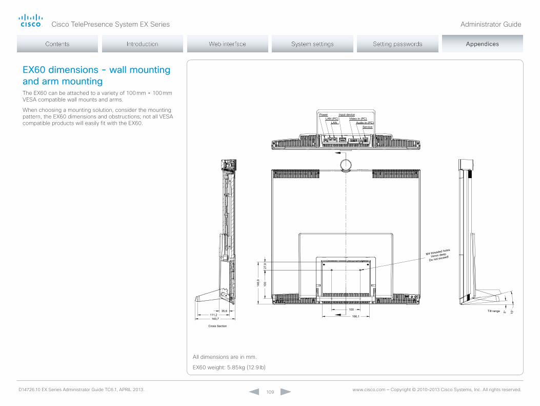
Cisco TelePresence System EX Series Administrator Guide
D14726.10 EX Series Administrator Guide TC6.1, APRIL 2013. www.cisco.com — Copyright © 2010–2013 Cisco Systems, Inc. All rights reserved. 109
EX60 dimensions - wall mounting and arm mountingThe EX60 can be attached to a variety of 100 mm × 100 mm VESA compatible wall mounts and arms.
When choosing a mounting solution, consider the mounting pattern, the EX60 dimensions and obstructions; not all VESA compatible products will easily fit with the EX60.
100
5° 15°35,6
140,7111,2
Cross Section
WALL OR ARM MOUNTING
The EX60 can be attached to a variety of 100mm x 100mm VESA compatible wall mounts and arms. Special consideration of the mounting pattern location, its surrounding dimensions and potential obstructions on the EX60 should be taken when choosing a mounting solution. Not all VESA compatible products will mount without complication to the EX60.
Weight: 5,85kgAll dimensions in mm
27,8
100
166,1
146,
9Do not exceed!
M4 threaded holes
14mm deep.
Tilt range
PowerLAN (PC)
LAN
Input deviceVideo in (PC)
Audio in (PC)Service
All dimensions are in mm.
EX60 weight: 5.85 kg (12.9 lb)

Cisco TelePresence System EX Series Administrator Guide
D14726.10 EX Series Administrator Guide TC6.1, APRIL 2013. www.cisco.com — Copyright © 2010–2013 Cisco Systems, Inc. All rights reserved. 110
Power button
Touch
Web
1. Power down the system by pressing and holding the power button until you see the shutdown message on screen. Release the button and wait for the system to shut down.
2. Press and hold the power button until the LED starts blinking slowly (approximately 10 seconds). Then release the button.
3. Within four seconds after the LED starts blinking, press the power button twice.
When the LED lights continuously, the system reverts to the default factory settings and restarts automatically. This will take a few minutes.
The system confirms the factory reset by displaying a notification on the main screen when up and running again. The notification disappears after approximately 10 seconds.
If you failed to press the power button twice within the four seconds, the system will not revert to the default factory settings, and you will not see the confirmation message. If this happens, go back to step 1 and try again.
Factory resettingIf you have to reset your video system to its default factory settings, we recommend that you use either the Touch controller or the web interface. If neither of these methods are available, you can use the video system’s power button.
When factory resetting the video system the following happens:
• Call logs will be deleted.• Passwords will be reset to default.• All system parameters will be reset to default values. • All files that have been uploaded to the system will be
deleted. This includes, but is not limited to, custom backgrounds, certificates, the favorites list and the inactive software image.
• Release keys and option keys will not be affected.• The system restarts automatically after the reset.
It is not possible to undo a factory reset.
1. Tap gently on the Touch screen if the unit is in sleep mode.
2. navigate to Settings ( ) > Administrator Settings > Reset.
3. Tap the Factory Reset button.
The system reverts to the default factory settings and restarts automatically. This will take a few minutes.
The system confirms the factory reset by displaying a notification on the main screen when up and running again. The notification disappears after approximately 10 seconds.
Tap Settings ( ) > System Information on the Touch controller to find the system's IP address (IPv4 or IPv6).
1. open a web browser and enter the IP address of the video system in the address bar.
2. navigate to Maintenance > Factory Reset.
3. Read the provided information carefully before you click Perform a factory reset.
4. If you are sure you want to perform a factory reset, click the red Reset button.
The system reverts to the default factory settings and restarts automatically. This will take a few minutes.
The system confirms the factory reset by displaying a notification on the main screen when up and running again. The notification disappears after approximately 10 seconds.
Power button
Power LED
If you want to backup your current configuration before you factory reset the unit, open a web browser and follow these steps:
• Enter the IP address of the video system in the address bar and sign in.
• navigate to Maintenance > Backup and Restore.• Click Take backup and follow the instructions to
save the file on your computer.

Cisco TelePresence System EX Series Administrator Guide
D14726.10 EX Series Administrator Guide TC6.1, APRIL 2013. www.cisco.com — Copyright © 2010–2013 Cisco Systems, Inc. All rights reserved. 111
TouchFactory resetting the Touch 8” controlleryou must use the new message indicator and mute buttons to reset the Touch 8” controller to its default factory settings.
When factory resetting the Touch controller the logs will be cleared, and the configuration and pairing information are lost.
The Touch controller restarts after the reset and receives a new configuration automatically from the video system.
It is not possible to undo a factory reset.
1. Locate the New message indicator and Mute buttons.
The New message indicator is a bit hard to see, but it is the button with the exclamation mark on it.
2. Press and hold the New message indicator until it lights up (approximately 10 seconds).
3. Press the Mute button twice.
The Touch controller automatically reverts to the default factory settings and restarts.
Mute button
New message indicator

Cisco TelePresence System EX Series Administrator Guide
D14726.10 EX Series Administrator Guide TC6.1, APRIL 2013. www.cisco.com — Copyright © 2010–2013 Cisco Systems, Inc. All rights reserved. 112
Technical specificationsThe EX90/EX60 units are delivered with a fully integrated codec, display, camera, microphone and loudspeakers, and a Touch controller with a detachable wide band handset.
* TE6.0 is a CUCm-only release and does not support all non-CUCm features from software versions TC 5.x and earlier. TC6.0 does not support all CUCm features from software version TE6.0. Full feature parity in TC software is introduced in TC6.1.
product compAtibiLity• Fully compatible with standards-compliant telepresence and video
systems
softwAre compAtibiLityEX90:• Cisco TelePresence Software
Version TC3.1 or later, and TE6.0 *
EX60: • Cisco TelePresence Software
Version TC4.0 or later, and TE6.0 *
components• Fully integrated unit including codec, display, camera, microphone
and loudspeakers
• Cables including: VGA-to-DVI-I cable, DVI-D cable, 3.5 mm jack audio cable, LAn cable, power adapter, and power cable
dispLAyEX90:• 24 in. LCD monitor
• Resolution: 1920 × 1200 (16:10)
• Contrast ratio: 1000:1
• Viewing angle: 160°
• Response time: 5 ms
• Brightness: 300 cd/m2
• 5° - 15° tilt
EX60:• 21.5 in. LCD monitor (with LED
backlight)
• Resolution: 1920 × 1080 (16:9)
• Contrast ratio: 1000:1
• Viewing angle: 170°
• Response time: 5 ms
• Brightness: 225 cd/m2
cAmerA• Cisco TelePresence PrecisionHD design
• Resolutions: 1080p30 and 720p60
• Auto focus
• Integrated privacy shutter
• Document camera mode
• multicoated all-glass optics
• 1/3-in., 2.1 megapixel CmoS sensor
EX90:• Horizontal field of view: 45°-65°
• Vertical field of view: 40°-27°
• Focus distance 0.3-infinity
• optical, motorized zoom
EX60:• Horizontal field of view: 50°
• Vertical field of view: 29°
• Focus distance 0.1-infinity
Audio system• Two stereo front speakers
• Integrated full-range microphone
• one 3.5 mm line-in jack for PC or other audio source
• Two 3.5 mm jack for headset
• Wideband handset
• Bluetooth version 2.1 + EDR
Only EX90:• Integrated subwoofer
• Support for Cisco TelePresence Table microphone 20
• HDmI audio input/output
pc And second source Video inputEX90:• DVI-I
• HDmI In
EX60:• DVI-I
supported pc input resoLutionsEX90:• SVGA (800 × 600) to
WUXGA (1920 × 1200)
EX60:• SVGA (800 × 600) to
1080p (1920 × 1080)
user interfAceCisco TelePresence Touch 8 controller
• Eight-inch projected capacitive touch screen
• Resolution: 800 × 480
LAnguAge support• Danish, Dutch, English, Finnish, French, German, Italian, Japanese,
Korean, norwegian, Portuguese-Brazilian, Russian, Simplified Chinese, Spanish, Swedish
power• Autosensing power supply
• 100–240 VAC, 50/60 Hz
EX90:• 150 W max
EX90 with Touch 8:• In video call: 110 W
• In standby: 58 W
EX60:• 75 W max
EX60 with Touch 8:• In video call: 46 W
• In standby: 31 W
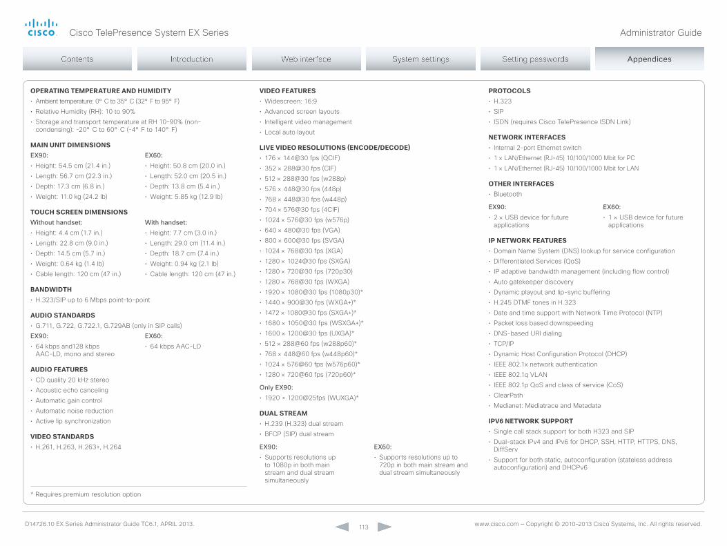
Cisco TelePresence System EX Series Administrator Guide
D14726.10 EX Series Administrator Guide TC6.1, APRIL 2013. www.cisco.com — Copyright © 2010–2013 Cisco Systems, Inc. All rights reserved. 113
* Requires premium resolution option
operAting temperAture And humidity• Ambient temperature: 0° C to 35° C (32° F to 95° F)
• Relative Humidity (RH): 10 to 90%
• Storage and transport temperature at RH 10–90% (non-condensing): -20° C to 60° C (-4° F to 140° F)
mAin unit dimensionsEX90:• Height: 54.5 cm (21.4 in.)
• Length: 56.7 cm (22.3 in.)
• Depth: 17.3 cm (6.8 in.)
• Weight: 11.0 kg (24.2 lb)
EX60:• Height: 50.8 cm (20.0 in.)
• Length: 52.0 cm (20.5 in.)
• Depth: 13.8 cm (5.4 in.)
• Weight: 5.85 kg (12.9 lb)
touch screen dimensionsWithout handset:• Height: 4.4 cm (1.7 in.)
• Length: 22.8 cm (9.0 in.)
• Depth: 14.5 cm (5.7 in.)
• Weight: 0.64 kg (1.4 lb)
• Cable length: 120 cm (47 in.)
With handset:• Height: 7.7 cm (3.0 in.)
• Length: 29.0 cm (11.4 in.)
• Depth: 18.7 cm (7.4 in.)
• Weight: 0.94 kg (2.1 lb)
• Cable length: 120 cm (47 in.)
bAndwidth• H.323/SIP up to 6 mbps point-to-point
Audio stAndArds• G.711, G.722, G.722.1, G.729AB (only in SIP calls)
EX90:• 64 kbps and128 kbps
AAC-LD, mono and stereo
EX60:• 64 kbps AAC-LD
Audio feAtures• CD quality 20 kHz stereo
• Acoustic echo canceling
• Automatic gain control
• Automatic noise reduction
• Active lip synchronization
Video stAndArds• H.261, H.263, H.263+, H.264
Video feAtures• Widescreen: 16:9
• Advanced screen layouts
• Intelligent video management
• Local auto layout
LiVe Video resoLutions (encode/decode)• 176 × 144@30 fps (QCIF)
• 352 × 288@30 fps (CIF)
• 512 × 288@30 fps (w288p)
• 576 × 448@30 fps (448p)
• 768 × 448@30 fps (w448p)
• 704 × 576@30 fps (4CIF)
• 1024 × 576@30 fps (w576p)
• 640 × 480@30 fps (VGA)
• 800 × 600@30 fps (SVGA)
• 1024 × 768@30 fps (XGA)
• 1280 × 1024@30 fps (SXGA)
• 1280 × 720@30 fps (720p30)
• 1280 × 768@30 fps (WXGA)
• 1920 × 1080@30 fps (1080p30)*
• 1440 × 900@30 fps (WXGA+)*
• 1472 × 1080@30 fps (SXGA+)*
• 1680 × 1050@30 fps (WSXGA+)*
• 1600 × 1200@30 fps (UXGA)*
• 512 × 288@60 fps (w288p60)*
• 768 × 448@60 fps (w448p60)*
• 1024 × 576@60 fps (w576p60)*
• 1280 × 720@60 fps (720p60)*
Only EX90:• 1920 × 1200@25fps (WUXGA)*
duAL streAm• H.239 (H.323) dual stream
• BFCP (SIP) dual stream
EX90:• Supports resolutions up
to 1080p in both main stream and dual stream simultaneously
EX60:• Supports resolutions up to
720p in both main stream and dual stream simultaneously
protocoLs• H.323
• SIP
• ISDn (requires Cisco TelePresence ISDn Link)
networK interfAces• Internal 2-port Ethernet switch
• 1 × LAn/Ethernet (RJ-45) 10/100/1000 mbit for PC
• 1 × LAn/Ethernet (RJ-45) 10/100/1000 mbit for LAn
other interfAces• Bluetooth
EX90:• 2 × USB device for future
applications
EX60:• 1 × USB device for future
applications
ip networK feAtures• Domain name System (DnS) lookup for service configuration
• Differentiated Services (QoS)
• IP adaptive bandwidth management (including flow control)
• Auto gatekeeper discovery
• Dynamic playout and lip-sync buffering
• H.245 DTmF tones in H.323
• Date and time support with network Time Protocol (nTP)
• Packet loss based downspeeding
• DnS-based URI dialing
• TCP/IP
• Dynamic Host Configuration Protocol (DHCP)
• IEEE 802.1x network authentication
• IEEE 802.1q VLAn
• IEEE 802.1p QoS and class of service (CoS)
• ClearPath
• medianet: mediatrace and metadata
ipV6 networK support• Single call stack support for both H323 and SIP
• Dual-stack IPv4 and IPv6 for DHCP, SSH, HTTP, HTTPS, DnS, DiffServ
• Support for both static, autoconfiguration (stateless address autoconfiguration) and DHCPv6

Cisco TelePresence System EX Series Administrator Guide
D14726.10 EX Series Administrator Guide TC6.1, APRIL 2013. www.cisco.com — Copyright © 2010–2013 Cisco Systems, Inc. All rights reserved. 114
firewALL trAVersAL• Cisco TelePresence Expressway Technology
• H.460.18 and H.460.19 Firewall Traversal
embedded encryption• H.323/SIP point-to-point
• Standards-based: H.235v3 and Advanced Encryption Standard (AES)
• Automatic key generation and exchange
• Supported in dual stream
security feAtures• management via Secure HTTP (HTTPS) and Secure Shell (SSH)
protocol
• IP administration password
• Administrator menu password
• Disable IP services
• network settings protection
muLtipoint support• Cisco TelePresence multiway support (requires Cisco TelePresence
Video Communication Server [Cisco VCS] and Cisco TelePresence mCU)
• Ability to natively join multipoint conferences hosted on Cisco TelePresence multipoint Switch (CTmS)
Only EX90:• Four-way embedded SIP/H.323 multiPoint, reference multiSite
muLtisite(embedded multipoint)
Only EX90:• 4-way 720p30 Continuous Presence (CP) multiSite
• Full individual audio and video transcoding
• Individual layouts for each participant (CP layout without self view feature)
• H.323/SIP/VoIP in the same conference
• Best Impression (Automatic CP layouts)
• H.264, encryption and dual stream from any site
• IP downspeeding
• Dial in/Dial out
supported infrAstructure• Cisco Unified Communications manager 8.6.2 and newer
• Cisco TelePresence Video Communication Server (Cisco VCS)
• Cisco WebEx TelePresence Server
system mAnAgement• Support for the Cisco TelePresence management Suite
• Total management through embedded Simple network management Protocol (SnmP), Telnet, SSH, XmL, and Simple object Access Protocol (SoAP)
• Remote software upload: through web server, Secure Copy Protocol (SCP), HTTP, and HTTPS
directory serVices• Support for local directories (my Contacts)
• Corporate directory
• Unlimited entries using server directory supporting
• Lightweight Directory Access Protocol (LDAP) and H.350
• Unlimited number for corporate directory (available with Cisco TelePresence management Suite)
• Local directory: 200 numbers
• Received calls with date and time
• Placed calls with date and time
• missed calls with date and time
mtbf product reLiAbiLity/mtbf The predicted reliability is expressed in the expected random mean Time Between Failures (mTBF) for the electronic components based on the Power on Hours:
• Power on Hours (PoH) > 69 000 hours.
• Useful Life Cycle > 6 years.
ISo 9001 certificate is available upon request
ApproVALs
EU/EECDirective 2006/95/EC (Low Voltage Directive)
- Standard En 60950-1
Directive 2004/108/EC (EmC Directive)
- Standard En 55022, Class A
- Standard En 55024
- Standard En 61000-3-2/-3-3
• Directive 2011/65/EU (RoHS)
Warning: This is a class A product. In a domestic environment this product may cause radio interference in which case the user may be required to take adequate measures.
USAApproved according to UL 60950-1
Complies with FCC15B Class A
note: This equipment has been tested and found to comply with the limits for a Class A digital device, pursuant to part 15 of the FCC Rules. These limits are designed to provide reasonable protection against harmful interference when the equipment is operated in a commercial environment. This equipment generates, uses, and can radiate radio frequency energy and, if not installed and used in accordance with the instruction manual, may cause harmful interference to radio communications. operation of this equipment in a residential area is likely to cause harmful interference in which case the user will be required to correct the interference at his own expense.
CanadaApproved according to CAn/CSA C22.2 no. 60950-1
This Class A digital apparatus complies with Canadian ICES-003
Cet appareil numérique de la classe A est conforme à la norme nmB-003 du Canada
All specifications are subject to change without notice, system specifics may vary.
All images in these materials are for representational purposes only, actual products may differ.
Cisco and the Cisco Logo are trademarks of Cisco Systems, Inc. and/or its affiliates in the U.S. and other countries. A listing of Cisco’s trademarks can be found at www.cisco.com/go/trademarks. Third party trademarks mentioned are the property of their respective owners. The use of the word partner does not imply a partnership relationship between Cisco and any other company.
march 2013

Cisco TelePresence System EX Series Administrator Guide
D14726.10 EX Series Administrator Guide TC6.1, APRIL 2013. www.cisco.com — Copyright © 2010–2013 Cisco Systems, Inc. All rights reserved. 115
Current RFCs and drafts supported• RFC 1889 RTP: A Transport Protocol for Real-time
Applications• RFC 2190 RTP Payload Format for H.263 Video Streams• RFC 2460 Internet protocol, version 6 (IPv6) specification• RFC 2617 Digest Authentication• RFC 2782 DnS RR for specifying the location of services
(DnS SRV)• RFC 2976 The SIP InFo method• RFC 3016 RTP Payload Format for mPEG-4 Audio/Visual
Streams• RFC 3261 SIP: Session Initiation Protocol• RFC 3262 Reliability of Provisional Responses in SIP• RFC 3263 Locating SIP Servers• RFC 3264 An offer/Answer model with SDP• RFC 3311 UPDATE method• RFC 3361 DHCP option for SIP Servers• RFC 3420 Internet media Type message/sipfrag• RFC 3515 Refer method• RFC 3550 RTP: A Transport Protocol for Real-Time
Applications• RFC 3551 RTP Profile for Audio and Video Conferences
with minimal Control• RFC 3581 Symmetric Response Routing• RFC 3605 RTCP attribute in SDP• RFC 3711 The Secure Real-time Transport Protocol
(SRTP)• RFC 3840 Indicating User Agent Capabilities in SIP• RFC 3890 A Transport Independent Bandwidth modifier
for SDP• RFC 3891 The SIP “Replaces” Header• RFC 3892 Referred-By mechanism• RFC 3960 Early media• RFC 3986 Uniform Resource Identifier (URI): Generic
Syntax• RFC 4028 Session Timers in SIP
• RFC 4145 TCP-Based media Transport in the SDP• RFC 4235 An InVITE-Initiated Dialog Event Package for
the Session Initiation Protocol (SIP)• RFC 4566 SDP: Session Description Protocol• RFC 4568 SDP:Security Descriptions for media Streams• RFC 4574 The Session Description Protocol (SDP) Label
Attribute• RFC 4582 The Binary Floor Control Protocol
draft-ietf-bfcpbis-rfc4582bis-00 Revision of the Binary Floor Control Protocol (BFCP) for use over an unreliable transport
• RFC 4583 Session Description Protocol (SDP) Format for Binary Floor Control Protocol (BFCP) Streamsdraft-ietf-bfcpbis-rfc4583bis-00 Session Description Protocol (SDP) Format for Binary Floor Control Protocol (BFCP) Streams
• RFC 4585 Extended RTP Profile for RTCP-Based Feedback
• RFC 4587 RTP Payload Format for H.261 Video Streams• RFC 4629 RTP Payload Format for ITU-T Rec. H.263
Video• RFC 4733 RTP Payload for DTmF Digits, Telephony Tones
and Telephony Signals• RFC 4796 The SDP Content Attribute• RFC 4862 IPv6 stateless address autoconfiguration• RFC 5104 Codec Control messages in the RTP Audio-
Visual Profile with Feedback (AVPF)• RFC 5168 XmL Schema for media Control• RFC 5577 RTP Payload Format for ITU-T
Recommendation G.722.1• RFC 5589: SIP Call Control Transfer• RFC 5626 managing Client-Initiated Connections in the
Session Initiation Protocol (SIP)• RFC 5905 network Time Protocol Version 4: Protocol and
Algorithms Specification• RFC 6184 RTP Payload Format for H.264 Video
Supported RFCsThe RFC (Request for Comments) series contains technical and organizational documents about the Internet, including the technical specifications and policy documents produced by the Internet Engineering Task Force (IETF).
Cisco TelePresence System EX Series Administrator Guide
D14726.10 EX Series Administrator Guide TC6.1, APRIL 2013. www.cisco.com — Copyright © 2010–2013 Cisco Systems, Inc. All rights reserved. 116
In general, user documentation for the Cisco TelePresence products is available here:
► http://www.cisco.com/go/telepresence/docs
you have to choose your product category in the right pane until you find your product. This is the path you have to follow:
TelePresence >TelePresence Endpoints - Personal >
TelePresence Desktop >Cisco TelePresence Systems EX Series
Alternatively, you can use the following short-link to find the documentation:
► http://www.cisco.com/go/ex-docs
User documentation on the Cisco web siteThe documents are organized in the following categories:
Installation guides: Install and Upgrade > Install and Upgrade Guides
Getting started guide: Install and Upgrade > Install and Upgrade GuidesMaintain and Operate > Maintain and Operate Guides
Administrator guides: Maintain and Operate > Maintain and Operate Guides
User guides and Quick reference guides: Maintain and Operate > End-User Guides
Knowledge base articles and frequently asked questions: Troubleshoot and Alerts > Troubleshooting Guides
CAD drawings: Reference Guides > Technical References
Video conferencing room guidelines: Design > Design Guides
Software licensing information: Software Downloads, Release and General Information > Licensing Information
Regulatory compliance and safety information: Install and Upgrade > Install and Upgrade Guides
Software release notes: Software Downloads, Release and General Information > Release Notes
Cisco TelePresence System EX Series Administrator Guide
D14726.10 EX Series Administrator Guide TC6.1, APRIL 2013. www.cisco.com — Copyright © 2010–2013 Cisco Systems, Inc. All rights reserved. 117
Intellectual property rights
THE SPECIFICATIonS AnD InFoRmATIon REGARDInG THE PRoDUCTS In THIS mAnUAL ARE SUBJECT To CHAnGE WITHoUT noTICE. ALL STATEmEnTS, InFoRmATIon, AnD RECommEnDATIonS In THIS mAnUAL ARE BELIEVED To BE ACCURATE BUT ARE PRESEnTED WITHoUT WARRAnTy oF Any KInD, EXPRESSED oR ImPLIED. USERS mUST TAKE FULL RESPonSIBILITy FoR THEIR APPLICATIon oF Any PRoDUCTS.
THE SoFTWARE LICEnSE AnD LImITED WARRAnTy FoR THE ACComPAnyInG PRoDUCT ARE SET FoRTH In THE InFoRmATIon PACKET THAT SHIPPED WITH THE PRoDUCT AnD ARE InCoRPoRATED HEREIn By THIS REFEREnCE. IF yoU ARE UnABLE To LoCATE THE SoFTWARE LICEnSE oR LImITED WARRAnTy, ConTACT yoUR CISCo REPRESEnTATIVE FoR A CoPy.
The Cisco implementation of TCP header compression is an adaptation of a program developed by the University of California, Berkeley (UCB) as part of UCB’s public domain version of the UnIX operating system. All rights reserved. Copyright © 1981, Regents of the University of California.
noTWITHSTAnDInG Any oTHER WARRAnTy HEREIn, ALL DoCUmEnT FILES AnD SoFTWARE oF THESE SUPPLIERS ARE PRoVIDED “AS IS” WITH ALL FAULTS. CISCo AnD THE ABoVE-nAmED SUPPLIERS DISCLAIm ALL WARRAnTIES, EXPRESSED oR ImPLIED, InCLUDInG, WITHoUT LImITATIon, THoSE oF mERCHAnTABILITy, FITnESS FoR A PARTICULAR PURPoSE AnD nonInFRInGEmEnT oR ARISInG FRom A CoURSE oF DEALInG, USAGE, oR TRADE PRACTICE.
In no EVEnT SHALL CISCo oR ITS SUPPLIERS BE LIABLE FoR Any InDIRECT, SPECIAL, ConSEQUEnTIAL, oR InCIDEnTAL DAmAGES, InCLUDInG, WITHoUT LImITATIon, LoST PRoFITS oR LoSS oR DAmAGE To DATA ARISInG oUT oF THE USE oR InABILITy To USE THIS mAnUAL, EVEn IF CISCo oR ITS SUPPLIERS HAVE BEEn ADVISED oF THE PoSSIBILITy oF SUCH DAmAGES.
Cisco and the Cisco Logo are trademarks of Cisco Systems, Inc. and/or its affiliates in the U.S. and other countries. A listing of Cisco’s trademarks can be found at www.cisco.com/go/trademarks. Third party trademarks mentioned are the property of their respective owners. The use of the word partner does not imply a partnership relationship between Cisco and any other company. (1005R)
Any Internet Protocol (IP) addresses and phone numbers used in this document are not intended to be actual addresses and phone numbers. Any examples, command display output, network topology diagrams, and other figures included in the document are shown for illustrative purposes only. Any use of actual IP addresses or phone numbers in illustrative content is unintentional and coincidental.
TAnDBERG is now a part of Cisco. TAnDBERG® is a registered trademark belonging to Tandberg ASA.
Cisco contactson our web site you will find an overview of the worldwide Cisco contacts.
Go to: ► http://www.cisco.com/web/siteassets/contacts
Corporate Headquarters
Cisco Systems, Inc.
170 West Tasman Dr.
San Jose, CA 95134 USA