Administering Cisco VTS · Administering Cisco VTS Thischapterhasthefollowingtopics: •...
24
Administering Cisco VTS This chapter has the following topics: • Setting up System, page 1 • Modifying Login Banners, page 2 • Setting Global Route Reflector, page 3 • Registering the Virtual Machine Manager using GUI, page 3 • Integrating Cisco VTS with Multiple Virtual Machine Managers, page 5 • Backing up the Database in non HA Mode, page 13 • Restoring the Database in non HA Mode, page 14 • Backing up the Database in HA Mode, page 14 • Restoring the Database in HA Mode, page 16 • Configuring Syslog for Monitoring Logs, page 17 • Viewing HA Status, page 20 • Enabling External Authentication and Authorization, page 21 • Enabling Accounting and Logging, page 22 Setting up System To set up the system: Step 1 Go to Administration > System Settings. The System Settings page appears. Step 2 Enter the DHCP Server IPv4 address. This can be a valid IPv4 address. Step 3 Enter the DHCP Server IPv6 address. This can be a valid IPv6 address. You must ensure that the DHCP server is reachable from tenant leaves. The addresses need to be on the underlay side, not a management IP. Cisco Virtual Topology System (VTS) 2.6.1 User Guide 1
Transcript of Administering Cisco VTS · Administering Cisco VTS Thischapterhasthefollowingtopics: •...
Administering Cisco VTS
This chapter has the following topics:
• Setting up System, page 1
• Modifying Login Banners, page 2
• Setting Global Route Reflector, page 3
• Registering the Virtual Machine Manager using GUI, page 3
• Integrating Cisco VTS with Multiple Virtual Machine Managers, page 5
• Backing up the Database in non HA Mode, page 13
• Restoring the Database in non HA Mode, page 14
• Backing up the Database in HA Mode, page 14
• Restoring the Database in HA Mode, page 16
• Configuring Syslog for Monitoring Logs, page 17
• Viewing HA Status, page 20
• Enabling External Authentication and Authorization, page 21
• Enabling Accounting and Logging, page 22
Setting up SystemTo set up the system:
Step 1 Go to Administration > System Settings.The System Settings page appears.
Step 2 Enter the DHCP Server IPv4 address. This can be a valid IPv4 address.Step 3 Enter the DHCP Server IPv6 address. This can be a valid IPv6 address.
You must ensure that the DHCP server is reachable from tenant leaves. The addresses need to be on the underlay side,not a management IP.
Cisco Virtual Topology System (VTS) 2.6.1 User Guide 1
Step 4 Enter the AnyCast GWMac. This is mandatory. Click ? for information about the format.Step 5 Choose the VTF Mode you want to use. VTF L2 mode means the Hosts in Host Inventory can have vtf-l2 as virtual
switch option. The other option is VTF-VTEP mode which means the Hosts in Host Inventory can have vtf-vtep as thevirtual switch option.
For OpenStack, VTFL2mode is supported only onOpenStackNewton.Note
• VTEP
• L2—If you want to use VTF as an L2 switch. This is the default.
Step 6 Specify the Out-of-Sync Commit behavior to control the Check Sync feature. See Synchronizing Configuration fordetails about the synchronizing configuration using the Config Sync feature. Choose one of the following:Choose:
• Accept— Check sync feature in network inventory will be disabled.
• Reject— Check sync feature in network inventory will be enabled.
Step 7 Enable/disable Device South Bound Lock—Device southbound lock is enabled by default. When VTS has a redundantpair or group, it is possible for a transaction to succeed even when one or more of the redundant members are down, aslong as one device is up. When the transaction comes, VTS checks the connectivity to the redundant devices and if itcan not reach one of the devices, the admin state of the device will be changed to southbound-locked and the transactionconfiguration will only be pushed to the active devices. In order for the southbound lock feature to work, you must createa umap and provide the credentials that NSO will use, in the authgroup "vts-default" . This feature currently supportsthe following redundant groups:
• VPC Pair
• ESI Group
• Static Multi-Homed devices
• DCI
• VTSR
Step 8 Click Submit.
Modifying Login BannersThe Login Banners page lets you modify the text that appears on the VTS login page and Home page.
Step 1 Go to Administration > Login Banners. The Login Banners page appears.Step 2 Modify the text in the Before login Text text box, to update the text that appears on the VTS login screen.Step 3 Modify the text in the After login Text text box, to update the text that appears on the Home page after you log in.Step 4 Click Submit.
Cisco Virtual Topology System (VTS) 2.6.1 User Guide2
Administering Cisco VTSModifying Login Banners
Setting Global Route ReflectorYou have the option to either use an inline route reflector, or global route reflector.
To set the global route reflector:
Step 1 Go to Administration > Route Reflector.Step 2 Use the toggle switch to choose Global.
The Spine has to be selected as route reflector under global RR so that it is available for all other devices. Thisshould be done before you create the admin domain.
Note
Step 3 Select the device.Step 4 Click Save.
Registering the Virtual Machine Manager using GUIYou can register the VMM using the VTS GUI. You can also specify whether the VMM you register is atrusted or an untrusted VMM.
For cluster-based deployments, you must install the plugin on each node.Note
To do this:
Step 1 Go to Administration > Virtual Machine Manager.Step 2 Click the Add (+) button.
The Register VMM page is displayed.
Step 3 Enter the VMM Details:
• Name—Name of the VMM.
• Version—Specify the version from the drop-down. If you choose openstack-newton as the Version in the 'Version'drop-down it displays a question 'Do you want VTS to install VMM plugin components?'.
If you choose No, enter the VMM ID. You can enter the VMM ID present in the file/etc/neutron/plugins/ml2/ml2_conf.ini in the controller machine. By default, Yes is chosen.
• Mode—Whether the VMM has been registered as Trusted or Untrusted.
• API Endpoint Details—The fields differ based on the VMM you choose.
◦API Endpoint Details for OpenStack
Cisco Virtual Topology System (VTS) 2.6.1 User Guide 3
Administering Cisco VTSSetting Global Route Reflector
◦API Protocol:IP Address:Port—VMM service endpoint's IPv4/IP6 address and port. Make sure you usethe same IP address format (IPv4/IPv6) for all IP address fields. Mixed mode is not supported.
◦Keystone Protocol:IP Address:Port—Keystone protocol, IP address and port for OpenStack.
◦Openstack Admin Project—Tenant with Administrator privileges in OpenStack. This can be any tenantwith Administrator privileges. Any change to this tenant name, username, and passphrase needs to beupdated in Cisco VTS for Multi-VMM operations to work properly.
◦Admin User Name—admin user for the admin project in OpenStack.
◦Admin Passphrase—Password of the admin user.
◦API Endpoint Details for vCenter. This is optional.
◦API Protocol:IP Address:Port—VMM service endpoint's IPv4/IP6 address and port. Make sure you usethe same IP address format (IPv4/IPv6) for all IP address fields. Mixed mode is not supported.
◦Datacenter—The name of the datacenter for which Cisco VTS acts as the controller.
◦Admin User Name—Username of the vCenter VMM.
◦Admin Passphrase—Password of the vCenter VMM.
Step 4 Click Register.After the VMM is registered successfully, the Plugin sections opens up.
Step 5 For OpenStack:If you choose No for the question 'Do you want VTS to install VMM plugin components?' in VMM Details,the radio button mentioned in a) is not displayed. It has only the Neutron Server section. The Add NeutronServer popup has the username and password as optional entries. You can choose not to give those. In that caseCisco VTS only saves the IP address. If you enter the Neutron server details you get an option to Save andValidate the plugin installation.
Note
a) Select the desired radio button to specify whether you want to Install plug in with Red Hat OSP Director or not. Ifyou select Yes, enter the following details:
• OSP Director IP Address
• OSP Director User name
• OSP Director Passphrase
b) Click Save. The Neutron Servers section opens up.c) Click Add (+) to add a Neutron Server. The Add Neutron Server popup is displayed.d) Enter the Server IP Address and the Server User Namee) Click Save and Install Plugin. You may add more Neutron Servers using the Add (+) option, if you have multiple
controllers (HA Mode). The Server Plugin Installation status shows whether the installation was a success.If you had opted not to use OSP Director, you will need to enter the password for the Neutron servers whileadding the servers.
Note
In case the Plugin Installation Status in the Virtual Machine Manager page shows the failure icon, you may chooseto edit the VMM using the Edit option and rectify the error. Click the Server Plugin Status icon to view details of theerror.
For vCenter:
Cisco Virtual Topology System (VTS) 2.6.1 User Guide4
Administering Cisco VTSRegistering the Virtual Machine Manager using GUI
a) Enter the following in the Plugin details section:If you had entered the API endpoint details, the Plugin details will get populated automatically.Note
• IP Address : Port
• Admin User Name
• Admin Passphrase
To delete a VMM, select the check box corresponding to the VMM you need to delete, and click the delete (X) icon.The VMM is deleted after you click Delete in the Confirm Delete popup.
Uninstalling the OpenStack PluginTo uninstall the OpenStack plugin from Neutron server:
Step 1 Go to Administration > Virtual Machine Manager.Step 2 Select the specific VMM.Step 3 Go to Neutron server plugin section, which shows the list of Neutron servers on which you have installed OpenStack
plugin.Step 4 Check the checkbox next to the neutron server row, and click on “-“ sign next to it. This uninstalls the plugin.
Integrating Cisco VTS with Multiple Virtual Machine ManagersYou can integrate Cisco VTS with multiple Virtual Machine Managers while managing a single data centerfabric.
We recommend that you use an external DHCP server for your Multi VMM (MVMM) setup.Note
Cisco VTS, which manages hardware and software overlays, registers to multiple VMMs and enables:
• Tenant, router and network in Cisco VTS to be provisioned via Openstack or vCenter
• Cisco VTS to provision the same Tenant/Router/Network across different VMMs
The MVMM feature is supported on:
• vCenter/VMware ESXi 6.0 Update 2 and vCenter/VMware ESXi 6.5 Update 1
• Openstack Liberty and Newton
Cisco Virtual Topology System (VTS) 2.6.1 User Guide 5
Administering Cisco VTSUninstalling the OpenStack Plugin
VMM Registration Modes
When you register a VMM with Cisco VTS, you can specify whether the VMM is a trusted VMM or anuntrusted VMM. For information about registering VMMs, see Registering the Virtual Machine Managerusing GUI, on page 3
Trusted VMM
A trusted VMM is one where the VMM administrator initiates service creation, and this gets reflected in VTCand the fabric. From trusted VMMs, Cisco VTS learns/discovers networks and auto-creates a network objectin Cisco VTS.
In trusted mode:
• Cisco VTS registers with multiple VMMs and installs the appropriate plugins on the VMMs.
• Cisco VTS trusts the VMMs and accepts the tenant/network information published by VMM to CiscoVTS.
• VMM publishes the network information using the VTS plugin and the REST APIs exposed by CiscoVTS.
Cisco VTS supports the following variants in trusted mode:
• Same Tenant/Disjoint Networks—In this variant, Cisco VTS integrates with two or more VMMs, and
◦Allows the VMMs to share the same tenant, but work on disjoint networks.
◦In case two or more VMMs need to share the same tenant, the operators of the VMMs have toco-ordinate on the names before sending the network information to Cisco VTS. Cisco VTS usesthe tenant name and the network name to identify the tenant and network.
◦Allows each VMM to create its own network to attach their respective workloads.
◦Cisco VTS admin provisions an overlay router using the VTS GUI to bring the networks togetherby L3 routing.
◦Cisco VTS admin can add an external network to the overlay router created above so that the VRFcorresponding to overlay router can be extended to the DCI to facilitate MPLS L3VPN or internetconnectivity.
• Same Tenant/Same Network—In this variant, Cisco VTS integrates with two or more VMMs, and
◦Allows the VMMs to share the same tenant, and also share the same networks, in order to attachtheir respective workloads.
◦In case two or more VMMs need to share the same tenant, the operators of the VMMs have toco-ordinate on the names before sending the network information to Cisco VTS.
Untrusted VMM
An untrusted VMM is one where the VMM administrator cannot create tenant/router/network service. Instead,the Cisco VTS administrator is the one who creates these services on these VMMs. Cisco VTS rejects anyservice creation call from an untrusted VMM.
In untrusted mode, Cisco VTS:
• Registers with multiple VMMs and installs its plugin on the VMMs.
Cisco Virtual Topology System (VTS) 2.6.1 User Guide6
Administering Cisco VTSIntegrating Cisco VTS with Multiple Virtual Machine Managers
• Does not trust the VMMs and reject the tenant/network information published by VMMs to VTS.
• Can publish the Tenant/Network information to the VMMs.
Cisco VTS supports the following variants in the untrusted mode:
• Same Tenant/Disjoint Networks—In this variant, Cisco VTS integrates with two or more VMMs, and
◦Allows the VMMs to share the same tenant, but work on disjoint networks.
◦In case Cisco VTS needs two or more VMMs to share the same tenant, VTS admin publishes thenetwork information to the VMMs. VMMs sync the tenant information with Cisco VTS using theVTS plugin and the REST APIs exposed by VTS.
◦Creates disjoint networks for each of the VMMs and publishes it individually to the VMMs. VTSallows each VMM to create its own network to attach their respective workloads.
◦Cisco VTS admin provisions an overlay router using the VTS GUI to bring the networks togetherby L3 routing.
◦Cisco VTS admin can add an external network to the Overlay router created above so that the VRFcorresponding to overlay router can be extended to DCI to facilitate MPLS L3VPN or internetconnectivity.
• Same Tenant/Same Network—In this variant, VTS integrates with two or more VMMs, and
◦Allows the VMMs to share the same tenant, and also the networks.
◦Enables VMMs to share the same tenant. VTS admin publishes the tenant information individuallyto each VMM. VMM syncs the tenant information with Cisco VTS using the VTS plugin and theREST APIs exposed by Cisco VTS.
◦Creates networks and publish it individually to the VMMs. Cisco VTS allows each VMM to attachtheir workloads to the networks.
Workflows in MVMM mode of Operation
To support the above modes, Cisco VTS:
• Enables you to merge the private L2 networks on different VMMs to create a Multi VMM L2 network.The private L2 networks are created by the individual VMMs and the merge operation is controlled bythe Cisco VTS administrator. Cisco VTS' involvement is to coalesce two or more network objects inthe VTS database into one. After a successful merge operation, all the networks would be tied togetherby a unique L2 VNID. This means that the VLAN allocation scheme to VMM private L2 networkremains intact. Even if there are workloads belonging to two different VMMs are placed on the sameleaf node, there could be two different VLAN allocations, but the same VNI allocation. Traffic betweenthe two workloads will go through VXLAN encap/decap. The normal mode of VNI allocation in CiscoVTS is ‘dynamic’ (per admin domain) and is assigned per private L2 network.
• Learns L2 networks from trusted VMMs and publishes these to other untrusted VMM under the controlof VTS admin. The Cisco VTS GUI is used to create these networks and publish to untrusted VMMs.Cisco VTS can reuse the VNI that was assigned to the originating VMM and push that to the otheruntrusted VMMs. If there is no originating VMM (and VTS is the originator), then VNI allocation canhappen freely in Cisco VTS.
• Creates a router that can interconnect L2 networks across multiple VMMs.
Cisco Virtual Topology System (VTS) 2.6.1 User Guide 7
Administering Cisco VTSIntegrating Cisco VTS with Multiple Virtual Machine Managers
Merge and Publish Operations
The VTS administrator is responsible for deciding which networks need to be merged and which networksneed to be published to other VMMs.
•Merge operation—Cisco VTS learns and auto-creates a Mulit VMML2 network by combining privateL2 networks from multiple trusted VMMs . For a successful merge operation, the tenant name, networkname, subnet name, subnet CIDR, and underlaymulticast addressmust match. You can select one/multi/alltenants and networks within a source VMM, and then choose a list of VMMs within which the mergewould be in effect. Both the source and destination VMMs need to be trusted.
We recommend that you ensure that Shared Networks have unique names across alltenants and all VMMs. This is to avoid ambiguity related to network names, which youmight encounter during Multi VMM merge operations.
Note
• Publish operation—Cisco VTS initiates the creation of a Multi VMM L2 network on untrusted/trustedVMMs. This decides which network (regardless of the source) needs to be published to a list of VMMs.The VMMs can either be trusted or untrusted. Publish operation automatically pushes tenant and networkinformation on the target VMM.
A merged netwrok cannot be published. To publish, you need to remove the mergedefinition, and then do the publish operation.
Note
Important • Upon publishing, Cisco VTS does not create the users for a tenant that it creates in OpenStack. Toview the tenant project, user has to be assigned to the project. The OpenStack user has to attach auser to the tenant.
• Cisco VTS publishes networks to OpenStack as network type = vxlan. Before performing a publishoperation, make sure that the plugin.ini, which is located at /etc/neutron/plugin.ini, has the followingproperties with network type vxlan as one of the values, for example:type_drivers = vxlan, <network_type2>, <network_type3> … <network_type_n> [commaseparated list of network types]tenant_network_types = vxlan, <network_type2>, <network_type3> ….<network_type_n>[comma separated list of network types]
Also you need to uncomment the property vni_ranges and update with suitable range values. Forexample:# Comma-separated list of <vni_min>:<vni_max> tuples enumerating ranges of# VXLAN VNI IDs that are available for tenant network allocation (list value)#vni_ranges =vni_ranges =10:100
To make these configuration take effect, you need to restart the neutron-server.
In case of Openstack Newton these values are, by default, configured in plugin.ini asabove.
Note
Deleting Merged Networks
Cisco Virtual Topology System (VTS) 2.6.1 User Guide8
Administering Cisco VTSIntegrating Cisco VTS with Multiple Virtual Machine Managers
Individual VMMs can delete the merged networks from the VMMs as long as there is no workload attachedto it. Cisco VTS will keep that network until the last VMM integrated with it deletes the network.
Deleting Published NetworksYou cannot delete a network or subnet from VTS after a publish operation. You need to delete the publishoperation before you change network or subnet from the source VMM or VTS. If you update from sourceVMM, the target VMM will not get affected. If you update from the VTS GUI, the update will fail.
All operations on published networks can be initiated only from the VTS GUI. If the network was publishedfrom VMM 1 to VMM 2, then VMM 1 can remove the network, but the published network will still exist onVMM 2. If VTS published the network to VMM 2, then if VMM 2 deletes the network, Cisco VTS will notallow to delete the network as long as the publish definition exists.In order to delete a published network/subnet, you have to first unpublish the network, and then perform thedelete operation. To unpublish a published network you need to remove the publish definition before youdelete the network. To do this go to the source VMM, view the publish definition and deselect the networkwhich you want to unpublish.
If there is a network which has already been published in the reverse direction, that is, from the currenttarget to the source as per the UI, then, to unpublish it, you need to go to that target VMM, view the publishdefinition, and uncheck the check box for the network.
Note
Performing Merge Operation from VMMTo initiate a merge operation from the Virtual Machine Manager page:
Step 1 Go to Administration > Virtual Machine Manager.Step 2 Select the Source VMM and click on theMerge icon under the Multi VMM Operations column..
Merge window opens. The Source VMM is the one fromwhich the operation is initiated. It will be selected and highlightedby default.
Step 3 Click the radio button corresponding to the Target VMM.The Tenants from Source column lists the tenants that are available. You can use the Add (+) button to add a new tenantname. To add a new tenant, enter the tenant name in the text box, and click the tick icon. Click Delete (X) to delete.
This will take effect only after the tenant is actually created.Note
You can use the filter to view the available tenants or selected tenants. By default, it shows all tenants.
You may use the select all button to select all tenants. If you use the select all option, you can set the Include Tenantsthat will be created in future automatically toggle switch to Yes.
Step 4 Select the desired tenant(s).The Networks from Source column lists the Networks available in the source VMM, for that tenant. You can use theAdd (+) button to add a new network name. To add a new network, enter the network name in the text box, and clickthe tick icon. Click Delete (X) to delete.
This will take effect only after the network is actually created.Note
You can use the filter to view the available networks or selected networks. By default, it shows all networks.
Cisco Virtual Topology System (VTS) 2.6.1 User Guide 9
Administering Cisco VTSPerforming Merge Operation from VMM
Youmay use the select all button to select all networks . If you use the select all option, you can set the Include Networksthat will be created in future automatically toggle switch to Yes. This toggle switch will be set to Yes, also if you hadset Include Tenants that will be created in future automatically toggle switch to Yes.
Step 5 Select the desired networks. Click Save.
Performing Merge Operation from TenantTo initiate a merge operation from a tenant:
Step 1 Go to Tenants> Tenant Management.Step 2 Select the VMM from the drop-down. The tenants for the VMM are displayed.Step 3 Click theMerge icon under the Multi VMM Operations column for the desired tenant.Step 4 Click the radio button to select the Target VMM.Step 5 Select the Networks from Source to be merged.
You can use the Add (+) button to add a new network name. To add a new network, enter the network name in the textbox, and click the tick icon. Click Delete (X) to delete.
This will take effect only after the network is actually created.Note
You can use the filter to view the available networks or selected networks. By default, it shows all networks.
You may use the select all button to select all network. If you use the select all option, you can set the Include Networksthat will be created in future automatically toggle switch to Yes.
Step 6 Click Save.
Performing Merge Operation from NetworkTo initiate a merge operation from a network:
Step 1 Go to Overlay > Network.The Overlay / Network window appears.
Step 2 Select the source from the Select Source drop-down list.Step 3 Select the tenant from the Select Tenant drop-down list.Step 4 Click theMerge icon for the desired network.Step 5 Select the target VMM.Step 6 Select the network from the Network from Source column.Step 7 Click Save.
Cisco Virtual Topology System (VTS) 2.6.1 User Guide10
Administering Cisco VTSPerforming Merge Operation from Tenant
Performing Publish Operation from VMMTo publish from VMM:
Step 1 Go to Administration > Virtual Machine Manager.Step 2 Select the Source VMM and click the Publish icon under the Multi VMM Operations column..
The Publish window opens. The Source VMM is the one from which the operation is initiated. It will be selected andhighlighted by default.
Step 3 Click the radio button corresponding to the Target VMM,.The Tenants from Source column lists the tenants that are available. You can use the Add (+) button to add a new tenantname. To add a new tenant, enter the tenant name in the text box, and click the tick icon. Click Delete (X) to delete.
This will take effect only after the tenant is actually created.Note
You can use the filter to view the available tenants or selected tenants. By default, it shows all tenants.
Step 4 Select the desired tenant(s).The Networks from Source column lists the Networks available in the source VMM, for that tenant. You can use theAdd (+) button to add a new network name. To add a new network, enter the network name in the text box, and clickthe tick icon. Click Delete (X) to delete.
This will take effect only after the network is actually created.Note
You can use the filter to view the available networks or selected networks. By default, it shows all networks.
You may use the select all button to select all networks.
Step 5 Select the desired networks. Click Save.
Performing Publish Operation from TenantTo initiate a publish operation from Tenant:
Step 1 Go to Tenants> Tenant Management.Step 2 Select the VMM from the drop-down. The tenants for the VMM are displayed.Step 3 Click the Publish icon under the Multi VMM Operations column for the desired tenant.Step 4 Click the radio button to select the Target VMM.Step 5 Select the Networks from Source to be merged.
You can use the Add (+) New button to add a new network name. To add a new network, enter the network name in thetext box, and click the tick icon. Click Delete (X) to delete.
This will take effect only after the network is actually created.Note
You can use the filter to view the available networks or selected networks. By default, it shows all networks.
Cisco Virtual Topology System (VTS) 2.6.1 User Guide 11
Administering Cisco VTSPerforming Publish Operation from VMM
Step 6 Click Save.
Performing Publish Operation from Network
Step 1 Go to Overlay > Network.The Overlay / Network window appears.
Step 2 Select the source from the Select Source drop-down list.Step 3 Select the tenant from the Select Tenant drop-down list.Step 4 Click the Publish icon for the desired network.Step 5 Select the target VMM.Step 6 Select the Network from Source column.Step 7 Click Save.
Performing Publish Operation from VTSTo publish from VTS
Step 1 Go to Administration > Virtual Machine Manager.Step 2 Click the Publish icon from VTS icon.
The Publish window opens with the source as VTS. It is selected and highlighted by default.Step 3 Click the radio button corresponding to the Target VMM.
The Tenants from Source column lists the tenants that are available. You can use the Add (+) button to add a new tenantname. To add a new tenant, enter the tenant name in the text box, and click the tick icon.
This will take effect only after the tenant is actually created.Note
Click Delete (X) to delete a tenant you do not want to publish from VTS.You can use the filter to view the available tenants or selected tenants. By default, it shows all tenants.
Step 4 Select the desired tenant(s).The Networks from Source column lists the Networks available in the source VMM, for that tenant. You can use theAdd (+) button to add a new network name. To add a new network, enter the network name in the text box, and clickthe tick icon. Click Delete (X) to delete.
This will take effect only after the network is actually created.Note
You can use the filter to view the available networks or selected networks. By default, it shows all networks.
You may use the select all button to select all networks.
Step 5 Select the desired networks. Click Save.
Cisco Virtual Topology System (VTS) 2.6.1 User Guide12
Administering Cisco VTSPerforming Publish Operation from Network
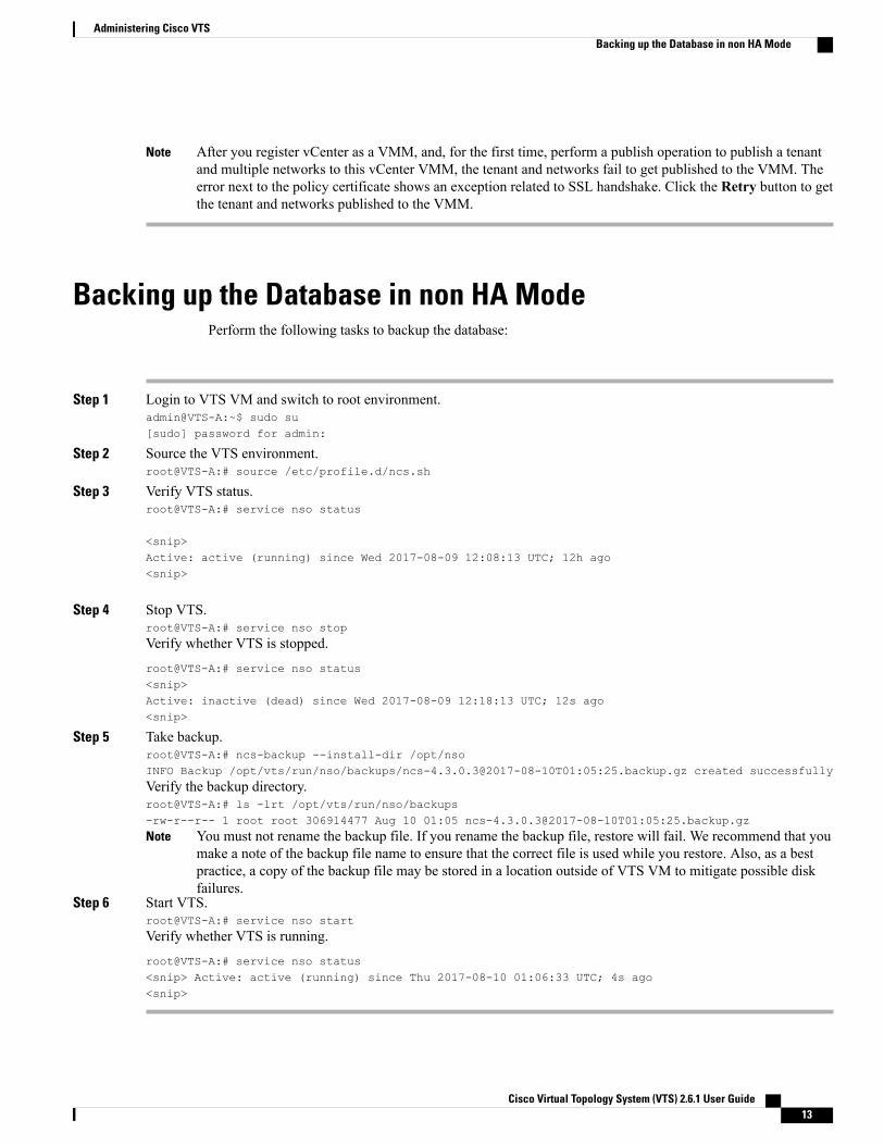
After you register vCenter as a VMM, and, for the first time, perform a publish operation to publish a tenantand multiple networks to this vCenter VMM, the tenant and networks fail to get published to the VMM. Theerror next to the policy certificate shows an exception related to SSL handshake. Click the Retry button to getthe tenant and networks published to the VMM.
Note
Backing up the Database in non HA ModePerform the following tasks to backup the database:
Step 1 Login to VTS VM and switch to root environment.admin@VTS-A:~$ sudo su[sudo] password for admin:
Step 2 Source the VTS environment.root@VTS-A:# source /etc/profile.d/ncs.sh
Step 3 Verify VTS status.root@VTS-A:# service nso status
<snip>Active: active (running) since Wed 2017-08-09 12:08:13 UTC; 12h ago<snip>
Step 4 Stop VTS.root@VTS-A:# service nso stop
Verify whether VTS is stopped.
root@VTS-A:# service nso status<snip>Active: inactive (dead) since Wed 2017-08-09 12:18:13 UTC; 12s ago<snip>
Step 5 Take backup.root@VTS-A:# ncs-backup --install-dir /opt/nsoINFO Backup /opt/vts/run/nso/backups/ncs-4.3.0.3@2017-08-10T01:05:25.backup.gz created successfully
Verify the backup directory.root@VTS-A:# ls -lrt /opt/vts/run/nso/backups-rw-r--r-- 1 root root 306914477 Aug 10 01:05 ncs-4.3.0.3@2017-08-10T01:05:25.backup.gz
You must not rename the backup file. If you rename the backup file, restore will fail. We recommend that youmake a note of the backup file name to ensure that the correct file is used while you restore. Also, as a bestpractice, a copy of the backup file may be stored in a location outside of VTS VM to mitigate possible diskfailures.
Note
Step 6 Start VTS.root@VTS-A:# service nso start
Verify whether VTS is running.
root@VTS-A:# service nso status<snip> Active: active (running) since Thu 2017-08-10 01:06:33 UTC; 4s ago<snip>
Cisco Virtual Topology System (VTS) 2.6.1 User Guide 13
Administering Cisco VTSBacking up the Database in non HA Mode
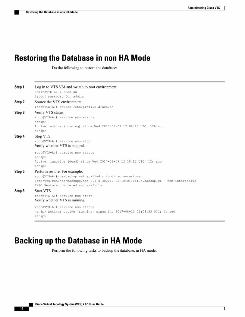
Restoring the Database in non HA ModeDo the following to restore the database:
Step 1 Log in to VTS VM and switch to root environment.admin@VTS-A:~$ sudo su[sudo] password for admin:
Step 2 Source the VTS environment.root@VTS-A:# source /etc/profile.d/ncs.sh
Step 3 Verify VTS status.root@VTS-A:# service nso status<snip>Active: active (running) since Wed 2017-08-09 12:08:13 UTC; 12h ago<snip>
Step 4 Stop VTS.root@VTS-A:# service nso stop
Verify whether VTS is stopped.
root@VTS-A:# service nso status<snip>Active: inactive (dead) since Wed 2017-08-09 12:18:13 UTC; 12s ago<snip>
Step 5 Perform restore. For example:root@VTS-A:#ncs-backup --install-dir /opt/nso --restore/opt/vts/run/nso/backups/ncs-4.3.0.3@2017-08-10T01:05:25.backup.gz --non-interactiveINFO Restore completed successfully
Step 6 Start VTS.root@VTS-A:# service nso start
Verify whether VTS is running.
root@VTS-A:# service nso status<snip> Active: active (running) since Thu 2017-08-10 01:06:33 UTC; 4s ago<snip>
Backing up the Database in HA ModePerform the following tasks to backup the database, in HA mode:
Cisco Virtual Topology System (VTS) 2.6.1 User Guide14
Administering Cisco VTSRestoring the Database in non HA Mode
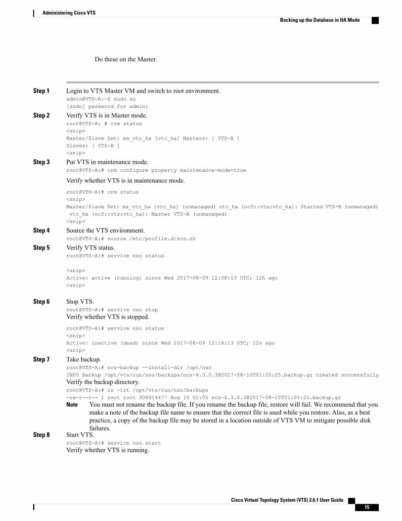
Do these on the Master.
Step 1 Login to VTS Master VM and switch to root environment.admin@VTS-A:~$ sudo su[sudo] password for admin:
Step 2 Verify VTS is in Master mode.root@VTS-A: # crm status<snip>Master/Slave Set: ms_vtc_ha [vtc_ha] Masters: [ VTS-A ]Slaves: [ VTS-B ]<snip>
Step 3 Put VTS in maintenance mode.root@VTS-A:# crm configure property maintenance-mode=true
Verify whether VTS is in maintenance mode.
root@VTS-A:# crm status<snip>Master/Slave Set: ms_vtc_ha [vtc_ha] (unmanaged) vtc_ha (ocf::vts:vtc_ha): Started VTS-B (unmanaged)vtc_ha (ocf::vts:vtc_ha): Master VTS-A (unmanaged)<snip>
Step 4 Source the VTS environment.root@VTS-A:# source /etc/profile.d/ncs.sh
Step 5 Verify VTS status.root@VTS-A:# service nso status
<snip>Active: active (running) since Wed 2017-08-09 12:08:13 UTC; 12h ago<snip>
Step 6 Stop VTS.root@VTS-A:# service nso stop
Verify whether VTS is stopped.
root@VTS-A:# service nso status<snip>Active: inactive (dead) since Wed 2017-08-09 12:18:13 UTC; 12s ago<snip>
Step 7 Take backup.root@VTS-A:# ncs-backup --install-dir /opt/nsoINFO Backup /opt/vts/run/nso/backups/ncs-4.3.0.3@2017-08-10T01:05:25.backup.gz created successfully
Verify the backup directory.root@VTS-A:# ls -lrt /opt/vts/run/nso/backups-rw-r--r-- 1 root root 306914477 Aug 10 01:05 ncs-4.3.0.3@2017-08-10T01:05:25.backup.gz
You must not rename the backup file. If you rename the backup file, restore will fail. We recommend that youmake a note of the backup file name to ensure that the correct file is used while you restore. Also, as a bestpractice, a copy of the backup file may be stored in a location outside of VTS VM to mitigate possible diskfailures.
Note
Step 8 Start VTS.root@VTS-A:# service nso start
Verify whether VTS is running.
Cisco Virtual Topology System (VTS) 2.6.1 User Guide 15
Administering Cisco VTSBacking up the Database in HA Mode
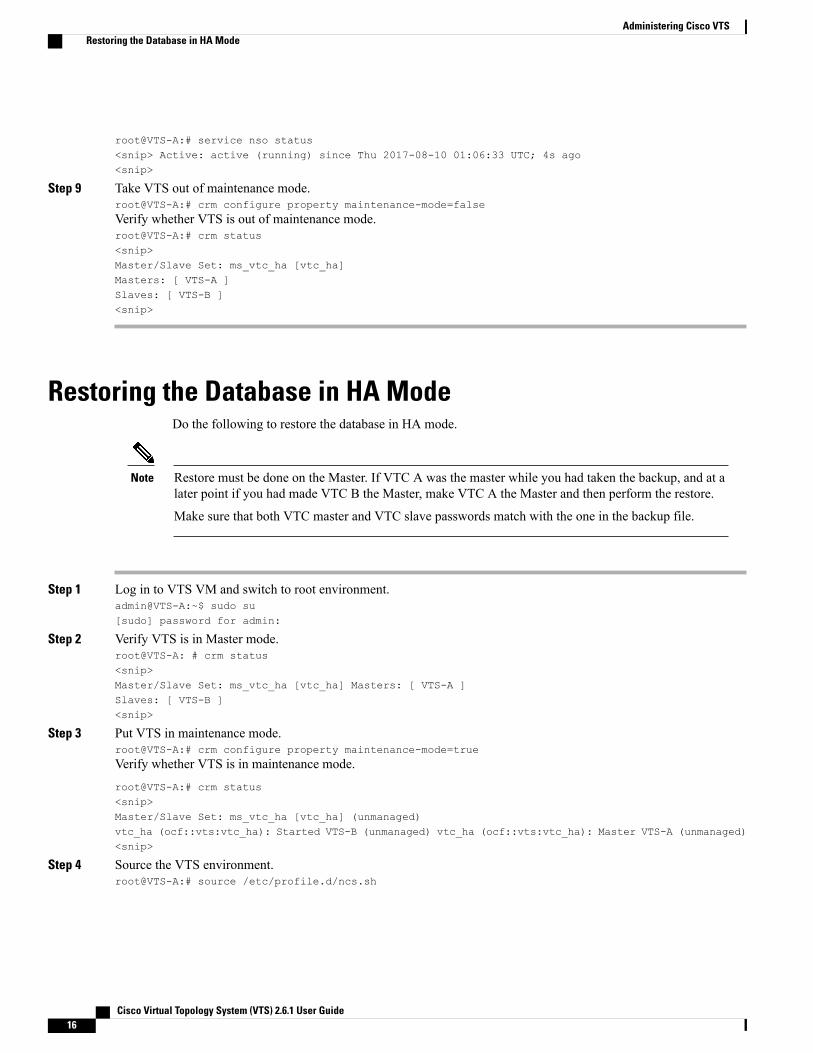
root@VTS-A:# service nso status<snip> Active: active (running) since Thu 2017-08-10 01:06:33 UTC; 4s ago<snip>
Step 9 Take VTS out of maintenance mode.root@VTS-A:# crm configure property maintenance-mode=false
Verify whether VTS is out of maintenance mode.root@VTS-A:# crm status<snip>Master/Slave Set: ms_vtc_ha [vtc_ha]Masters: [ VTS-A ]Slaves: [ VTS-B ]<snip>
Restoring the Database in HA ModeDo the following to restore the database in HA mode.
Restore must be done on the Master. If VTC A was the master while you had taken the backup, and at alater point if you had made VTC B the Master, make VTC A the Master and then perform the restore.
Make sure that both VTC master and VTC slave passwords match with the one in the backup file.
Note
Step 1 Log in to VTS VM and switch to root environment.admin@VTS-A:~$ sudo su[sudo] password for admin:
Step 2 Verify VTS is in Master mode.root@VTS-A: # crm status<snip>Master/Slave Set: ms_vtc_ha [vtc_ha] Masters: [ VTS-A ]Slaves: [ VTS-B ]<snip>
Step 3 Put VTS in maintenance mode.root@VTS-A:# crm configure property maintenance-mode=true
Verify whether VTS is in maintenance mode.
root@VTS-A:# crm status<snip>Master/Slave Set: ms_vtc_ha [vtc_ha] (unmanaged)vtc_ha (ocf::vts:vtc_ha): Started VTS-B (unmanaged) vtc_ha (ocf::vts:vtc_ha): Master VTS-A (unmanaged)<snip>
Step 4 Source the VTS environment.root@VTS-A:# source /etc/profile.d/ncs.sh
Cisco Virtual Topology System (VTS) 2.6.1 User Guide16
Administering Cisco VTSRestoring the Database in HA Mode
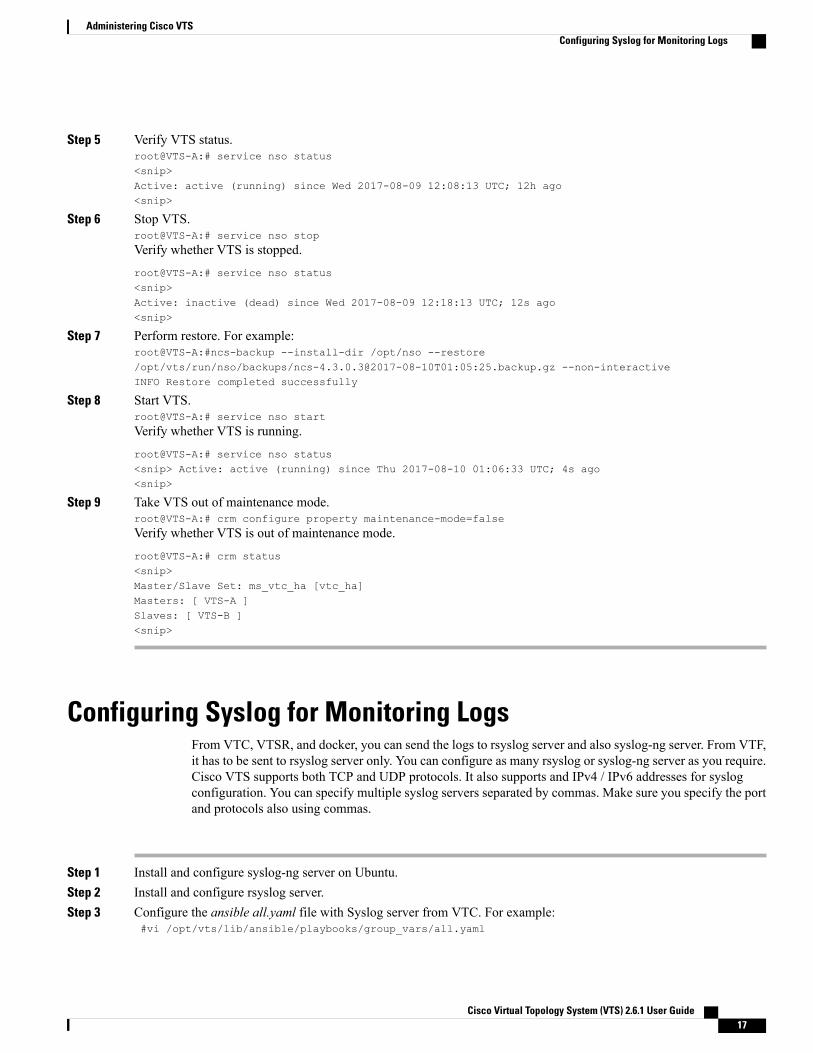
Step 5 Verify VTS status.root@VTS-A:# service nso status<snip>Active: active (running) since Wed 2017-08-09 12:08:13 UTC; 12h ago<snip>
Step 6 Stop VTS.root@VTS-A:# service nso stop
Verify whether VTS is stopped.
root@VTS-A:# service nso status<snip>Active: inactive (dead) since Wed 2017-08-09 12:18:13 UTC; 12s ago<snip>
Step 7 Perform restore. For example:root@VTS-A:#ncs-backup --install-dir /opt/nso --restore/opt/vts/run/nso/backups/ncs-4.3.0.3@2017-08-10T01:05:25.backup.gz --non-interactiveINFO Restore completed successfully
Step 8 Start VTS.root@VTS-A:# service nso start
Verify whether VTS is running.
root@VTS-A:# service nso status<snip> Active: active (running) since Thu 2017-08-10 01:06:33 UTC; 4s ago<snip>
Step 9 Take VTS out of maintenance mode.root@VTS-A:# crm configure property maintenance-mode=false
Verify whether VTS is out of maintenance mode.
root@VTS-A:# crm status<snip>Master/Slave Set: ms_vtc_ha [vtc_ha]Masters: [ VTS-A ]Slaves: [ VTS-B ]<snip>
Configuring Syslog for Monitoring LogsFrom VTC, VTSR, and docker, you can send the logs to rsyslog server and also syslog-ng server. From VTF,it has to be sent to rsyslog server only. You can configure as many rsyslog or syslog-ng server as you require.Cisco VTS supports both TCP and UDP protocols. It also supports and IPv4 / IPv6 addresses for syslogconfiguration. You can specify multiple syslog servers separated by commas. Make sure you specify the portand protocols also using commas.
Step 1 Install and configure syslog-ng server on Ubuntu.Step 2 Install and configure rsyslog server.Step 3 Configure the ansible all.yaml file with Syslog server from VTC. For example:
#vi /opt/vts/lib/ansible/playbooks/group_vars/all.yaml
Cisco Virtual Topology System (VTS) 2.6.1 User Guide 17
Administering Cisco VTSConfiguring Syslog for Monitoring Logs
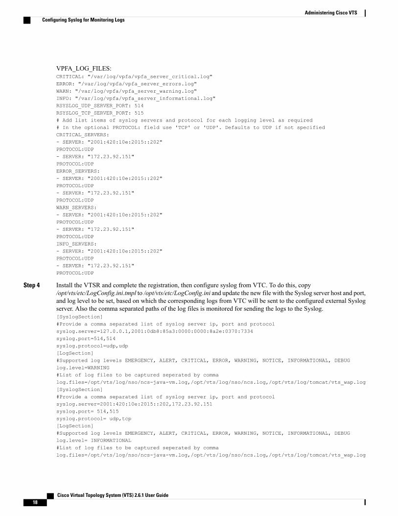
VPFA_LOG_FILES:CRITICAL: "/var/log/vpfa/vpfa_server_critical.log"ERROR: "/var/log/vpfa/vpfa_server_errors.log"WARN: "/var/log/vpfa/vpfa_server_warning.log"INFO: "/var/log/vpfa/vpfa_server_informational.log"RSYSLOG_UDP_SERVER_PORT: 514RSYSLOG_TCP_SERVER_PORT: 515# Add list items of syslog servers and protocol for each logging level as required# In the optional PROTOCOL: field use 'TCP' or 'UDP'. Defaults to UDP if not specifiedCRITICAL_SERVERS:- SERVER: "2001:420:10e:2015::202"PROTOCOL:UDP- SERVER: "172.23.92.151"PROTOCOL:UDPERROR_SERVERS:- SERVER: "2001:420:10e:2015::202"PROTOCOL:UDP- SERVER: "172.23.92.151"PROTOCOL:UDPWARN_SERVERS:- SERVER: "2001:420:10e:2015::202"PROTOCOL:UDP- SERVER: "172.23.92.151"PROTOCOL:UDPINFO_SERVERS:- SERVER: "2001:420:10e:2015::202"PROTOCOL:UDP- SERVER: "172.23.92.151"PROTOCOL:UDP
Step 4 Install the VTSR and complete the registration, then configure syslog from VTC. To do this, copy/opt/vts/etc/LogConfig.ini.tmpl to /opt/vts/etc/LogConfig.ini and update the new file with the Syslog server host and port,and log level to be set, based on which the corresponding logs from VTC will be sent to the configured external Syslogserver. Also the comma separated paths of the log files is monitored for sending the logs to the Syslog.[SyslogSection]#Provide a comma separated list of syslog server ip, port and protocolsyslog.server=127.0.0.1,2001:0db8:85a3:0000:0000:8a2e:0370:7334syslog.port=514,514syslog.protocol=udp,udp[LogSection]#Supported log levels EMERGENCY, ALERT, CRITICAL, ERROR, WARNING, NOTICE, INFORMATIONAL, DEBUGlog.level=WARNING#List of log files to be captured seperated by commalog.files=/opt/vts/log/nso/ncs-java-vm.log,/opt/vts/log/nso/ncs.log,/opt/vts/log/tomcat/vts_wap.log[SyslogSection]#Provide a comma separated list of syslog server ip, port and protocolsyslog.server=2001:420:10e:2015::202,172.23.92.151syslog.port= 514,515syslog.protocol= udp,tcp[LogSection]#Supported log levels EMERGENCY, ALERT, CRITICAL, ERROR, WARNING, NOTICE, INFORMATIONAL, DEBUGlog.level= INFORMATIONAL#List of log files to be captured seperated by commalog.files=/opt/vts/log/nso/ncs-java-vm.log,/opt/vts/log/nso/ncs.log,/opt/vts/log/tomcat/vts_wap.log
Cisco Virtual Topology System (VTS) 2.6.1 User Guide18
Administering Cisco VTSConfiguring Syslog for Monitoring Logs
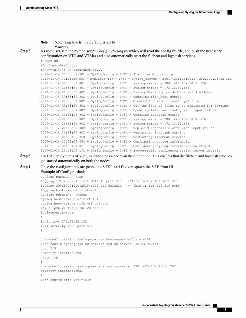
Note: Log levels , by default, is set toWarning.
Note
Step 5 As root user, run the python script ConfigureSyslog.py which will read the config ini file, and push the necessaryconfiguration on VTC and VTSRs and also automatically start the filebeat and logstash services.# sudo su -#ConfigureSyslog.pyroot@vts14:~# ConfigureSyslog.py2017-11-14 20:58:59,801 - SyslogConfig - INFO - Start reading configs.2017-11-14 20:58:59,801 - SyslogConfig - INFO - Syslog_server - 2001:420:10e:2015::202,172.23.92.1512017-11-14 20:58:59,801 - SyslogConfig - INFO - syslog server = 2001:420:10e:2015::2022017-11-14 20:58:59,801 - SyslogConfig - INFO - syslog server = 172.23.92.1512017-11-14 20:58:59,802 - SyslogConfig - INFO - Syslog Servers provided are valid address2017-11-14 20:58:59,802 - SyslogConfig - INFO - Updating file_beat config2017-11-14 20:58:59,802 - SyslogConfig - INFO - Created the main filebeat yml file.2017-11-14 20:58:59,802 - SyslogConfig - INFO - Got the list of files to be monitored for logging.2017-11-14 20:58:59,802 - SyslogConfig - INFO - Updating file_beat config with input values2017-11-14 20:58:59,802 - SyslogConfig - INFO - Updating logstash config2017-11-14 20:58:59,802 - SyslogConfig - INFO - syslog server = 2001:420:10e:2015::2022017-11-14 20:58:59,802 - SyslogConfig - INFO - syslog server = 172.23.92.1512017-11-14 20:58:59,802 - SyslogConfig - INFO - Replaced logstash config with input values2017-11-14 20:58:59,803 - SyslogConfig - INFO - Restarting logstash service2017-11-14 20:59:06,750 - SyslogConfig - INFO - Restarting filebeat service2017-11-14 20:59:07,054 - SyslogConfig - INFO - Configuring syslog information2017-11-14 20:59:07,071 - SyslogConfig - INFO - Configuring syslog information on vtsr012017-11-14 20:59:08,151 - SyslogConfig - INFO - Successfully configured syslog server details
Step 6 For HA deployments of VTC, execute steps 4 and 5 on the other node. This ensures that the filebeat and logstash servicesget started automatically on both the nodes.
Step 7 Once the configurations are pushed to VTSR and Docker, spawn the VTF from UI.Example of Config pushed:Configs pushed on VTSR:logging 172.23.92.151 vrf default port 515 //This is for TCP Port 515logging 2001:420:10e:2015::202 vrf default // This is for UDP 515 Portlogging hostnameprefix vtsr01Configs pushed on Docker:syslog host-name-prefix vtsr01syslog host-server vrfs vrf defaultipv6s ipv6 2001:420:10e:2015::202ipv6-severity-port!ipv4s ipv4 172.23.92.151ipv4-severity-port port 515!
vtsr-config syslog syslog-servers host-name-prefix vtsr01vtsr-config syslog syslog-servers syslog-server 172.23.92.151port 515severity informationalproto tcp!vtsr-config syslog syslog-servers syslog-server 2001:420:10e:2015::202severity informational!vtsr-config vtfs vtf VTF39
Cisco Virtual Topology System (VTS) 2.6.1 User Guide 19
Administering Cisco VTSConfiguring Syslog for Monitoring Logs
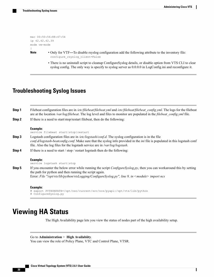
mac 00:50:56:88:47:54ip 42.42.42.39mode vm-mode!
Note • Only for VTF—To disable rsyslog configuration add the following attribute to the inventory file:configure_rsyslog_client=False
• There is no uninstall script to cleanup ConfigureSyslog details, or disable option from VTS CLI to clearsyslog config. The only way is specify to syslog server as 0.0.0.0 in LogConfig.ini and reconfigure it.
Troubleshooting Syslog Issues
Step 1 Filebeat configuration files are in /etc/filebeat/filebeat.yml and /etc/filebeat/filebeat_config.yml. The logs for the filebeatare at the location /var/log/filebeat. The log level and files to monitor are populated in the filebeat_config.yml file.
Step 2 If there is a need to start/stop/restart filebeat, then do the following:
Example:service filebeat start|stop|restart
Step 3 Logstash configuration files are in /etc/logstash/conf.d. The syslog configuration is in the fileconf.d/logstash-beatconfig.conf. Make sure that the syslog info provided in the ini file is populated in this logstash conffile. Also the log files for the logstash service are in /var/log/logstash.
Step 4 If there is a need to start / stop / restart logstash then do the following:
Example:service logstash start|stop
Step 5 If you encounter the below error while running the script ConfigureSyslog.py, then you can workaround this by settingthe path for python and then running the script again.Error: File "/opt/vts/lib/python/vtsLogging/ConfigureSyslog.py", line 9, in <module> import ncs
Example:# export PYTHONPATH=/opt/nso/current/src/ncs/pyapi:/opt/vts/lib/python# ConfigureSyslog.py
Viewing HA StatusThe High Availability page lets you view the status of nodes part of the high availability setup.
Go to Administration > High Availabiity.You can view the role of Policy Plane, VTC and Control Plane, VTSR.
Cisco Virtual Topology System (VTS) 2.6.1 User Guide20
Administering Cisco VTSTroubleshooting Syslog Issues
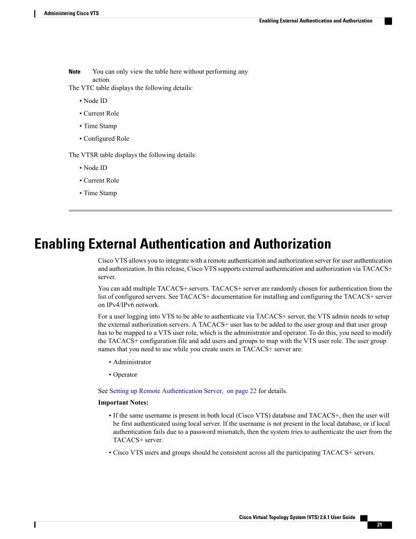
You can only view the table here without performing anyaction.
Note
The VTC table displays the following details:
• Node ID
• Current Role
• Time Stamp
• Configured Role
The VTSR table displays the following details:
• Node ID
• Current Role
• Time Stamp
Enabling External Authentication and AuthorizationCisco VTS allows you to integrate with a remote authentication and authorization server for user authenticationand authorization. In this release, Cisco VTS supports external authentication and authorization via TACACS+server.
You can add multiple TACACS+ servers. TACACS+ server are randomly chosen for authentication from thelist of configured servers. See TACACS+ documentation for installing and configuring the TACACS+ serveron IPv4/IPv6 network.
For a user logging into VTS to be able to authenticate via TACACS+ server, the VTS admin needs to setupthe external authorization servers. A TACACS+ user has to be added to the user group and that user grouphas to be mapped to a VTS user role, which is the administrator and operator. To do this, you need to modifythe TACACS+ configuration file and add users and groups to map with the VTS user role. The user groupnames that you need to use while you create users in TACACS+ server are:
• Administrator
• Operator
See Setting up Remote Authentication Server, on page 22 for details.
Important Notes:
• If the same username is present in both local (Cisco VTS) database and TACACS+, then the user willbe first authenticated using local server. If the username is not present in the local database, or if localauthentication fails due to a password mismatch, then the system tries to authenticate the user from theTACACS+ server.
• Cisco VTS users and groups should be consistent across all the participating TACACS+ servers.
Cisco Virtual Topology System (VTS) 2.6.1 User Guide 21
Administering Cisco VTSEnabling External Authentication and Authorization
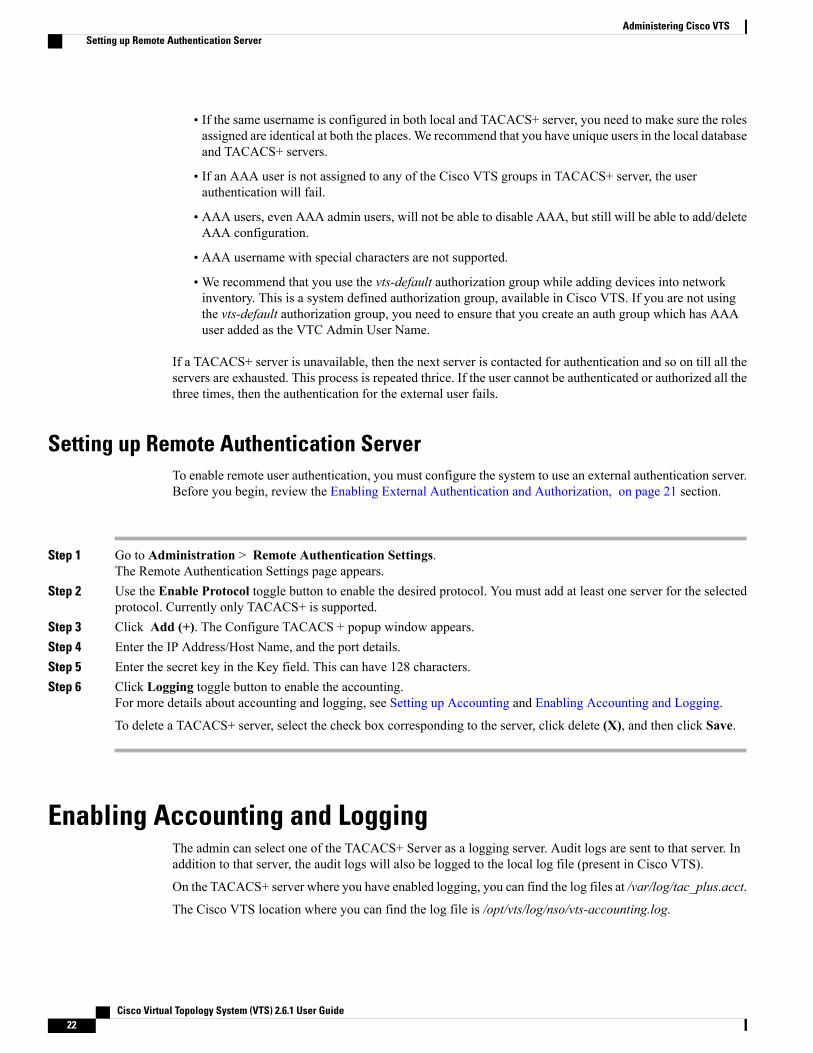
• If the same username is configured in both local and TACACS+ server, you need to make sure the rolesassigned are identical at both the places. We recommend that you have unique users in the local databaseand TACACS+ servers.
• If an AAA user is not assigned to any of the Cisco VTS groups in TACACS+ server, the userauthentication will fail.
• AAA users, even AAA admin users, will not be able to disable AAA, but still will be able to add/deleteAAA configuration.
• AAA username with special characters are not supported.
•We recommend that you use the vts-default authorization group while adding devices into networkinventory. This is a system defined authorization group, available in Cisco VTS. If you are not usingthe vts-default authorization group, you need to ensure that you create an auth group which has AAAuser added as the VTC Admin User Name.
If a TACACS+ server is unavailable, then the next server is contacted for authentication and so on till all theservers are exhausted. This process is repeated thrice. If the user cannot be authenticated or authorized all thethree times, then the authentication for the external user fails.
Setting up Remote Authentication ServerTo enable remote user authentication, you must configure the system to use an external authentication server.Before you begin, review the Enabling External Authentication and Authorization, on page 21 section.
Step 1 Go to Administration > Remote Authentication Settings.The Remote Authentication Settings page appears.
Step 2 Use the Enable Protocol toggle button to enable the desired protocol. You must add at least one server for the selectedprotocol. Currently only TACACS+ is supported.
Step 3 Click Add (+). The Configure TACACS + popup window appears.Step 4 Enter the IP Address/Host Name, and the port details.Step 5 Enter the secret key in the Key field. This can have 128 characters.Step 6 Click Logging toggle button to enable the accounting.
For more details about accounting and logging, see Setting up Accounting and Enabling Accounting and Logging.
To delete a TACACS+ server, select the check box corresponding to the server, click delete (X), and then click Save.
Enabling Accounting and LoggingThe admin can select one of the TACACS+ Server as a logging server. Audit logs are sent to that server. Inaddition to that server, the audit logs will also be logged to the local log file (present in Cisco VTS).
On the TACACS+ server where you have enabled logging, you can find the log files at /var/log/tac_plus.acct.
The Cisco VTS location where you can find the log file is /opt/vts/log/nso/vts-accounting.log.
Cisco Virtual Topology System (VTS) 2.6.1 User Guide22
Administering Cisco VTSSetting up Remote Authentication Server
Logs are collected every 120 seconds (default setting).
• Logs are collected every 120 seconds(default setting)Following are the fields that can be found in the log:
◦Client IP—Client IP from where the request was made
◦Server IP—VTS server IP
◦User Name—User who performs the transaction
◦Message—The model change in the transaction or the REST API url
◦Date/Time—The time when the change was made
◦Application Name—VTS (static value)
◦Operation Type—Derived from the change, could be CREATE, UPDATE or DELETE
◦Status—Success or Error (static value)
Setting up AccountingTo set up accounting, you must add one of the TACACS+ servers that are registered with Cisco VTS as thelogging server. You can do this while you add the remote authorization servers. If you have already addedremote authentication servers, you can select a server and edit it to make it the logging server.
You can have only one TACACS+ server as the logging server at a time.Note
Step 1 Go to Administration > Remote Authentication Settings.The Remote Authentication Settings page appears.
Step 2 Use the Enable Protocol toggle button to enable the desired protocol. You must add at least one configuration instancefor the selected protocol. Currently only TACACS+ is supported.
Step 3 Click Add (+). The Configure TACACS+ popup window appears.Step 4 Enter the IP Address/Host Name, and the port details.
Cisco VTS supports IPv4 and IPv6addresses.
Note
Step 5 Enter the secret key in the Key field. This can have 128 characters.Step 6 Click Logging toggle button to enable the accounting.Step 7 Click Add.Step 8 Click Save.
The logs get saved in the local VTS server and TACACS server.In Cisco VTS, you can see all the logs in vts-accounting.log, which has details like the Username, Date/Time, ApplicationName, Operation Type, Status, Sever IP, Client IP address, and the exact message about the transaction. Similarly, inthe TACACS server also you can see all the logs for the transactions.
Logs are collected every 120 seconds(default setting), and pushed to TACACS+ accounting server(for example,tac_plus.acct) and to VTC(vts-accounting.log).
Cisco Virtual Topology System (VTS) 2.6.1 User Guide 23
Administering Cisco VTSSetting up Accounting
The log file will be rotated once it reaches 100MB in size. The backup exists for 10 rotations, then gets deleted.
Cisco Virtual Topology System (VTS) 2.6.1 User Guide24
Administering Cisco VTSSetting up Accounting