ADICOS GSME Operating Manual · M-BM ADICOS M-Busmaster NT ADICOS Power Supply NT V40-A3 FDnet...
40
GTE Industrieelektronik GmbH Helmholtzstr. 21, 38-40 | D-41747 Viersen, GERMANY | [email protected] | +49(0)2162 / 3703-0 | www.gte.de EN 405-2010-003 EN40 Operating Manual GSME-M4 Fire Gas Detector GSME ®
Transcript of ADICOS GSME Operating Manual · M-BM ADICOS M-Busmaster NT ADICOS Power Supply NT V40-A3 FDnet...
GTE Industrieelektronik GmbHHelmholtzstr. 21, 38-40 | D-41747 Viersen, GERMANY | [email protected] | +49(0)2162 / 3703-0 | www.gte.de
EN
405-2010-003 EN40
Operating Manual
GSME-M4
Fire Gas Detector GSME®
Fire Gas Detector GSME - Operating manualDocument revision: 405-2010-003 EN40– Translation –
Manufacturer:GTE Industrieelektronik GmbHHelmholtzstr. 21, 38-4041747 ViersenGERMANY
Support hotline: +49 (0)2162 / 3703-29E-Mail: [email protected]
© 2017 GTE Industrieelektronik GmbH – This document and all figures contained may not be copied, changed, or distributed without explicit approval by the manufacturer!
Subject to technical changes!
ADICOS® and GSME® are registered trademarks of GTE Industrieelektronik GmbH.
IADICOS GSME 405-2010-003 EN40
ABSTRACT
Abstract
The Advanced Discovery System (in short: ADICOS) is used for early detection of fire scenarios in the industrial environment. It comprises different, independent detector units that enable inter-ference-resistant fulfillment of the detection objective defined during planning via suitable layout and parameterization.
The detector units are connected using the ADICOS M-Bus to a central unit, which enables voltage supply and parameterization of every individual detector and which stores all sensor data for statistical analyses.
ADICOS GSME are fire detectors equipped with semiconductor gas sensors and an intelligent analysis electronics, which can detect open and hidden smoldering fires through monitoring of the concentration of typical fire gases and report them via the ADICOS M-Bus and integrated alarm relays to the central unit.
If available interface modules are used, GSME can also be integrated into the fire alarm sys-tems of common manufacturers.

II ADICOS GSME405-2010-003 EN40
IIIADICOS GSME 405-2010-003 EN40
CONTENTS
Contents
1 About this manual . . . . . . . . . . . . . . . . . . . . . . . . . . . . . . . . . . . . . . . . . . 31.1 Objective . . . . . . . . . . . . . . . . . . . . . . . . . . . . . . . . . . . . . . . . . . . 31.2 Explanation of symbols . . . . . . . . . . . . . . . . . . . . . . . . . . . . . . . . . . 31.3 Abbreviations. . . . . . . . . . . . . . . . . . . . . . . . . . . . . . . . . . . . . . . . . 41.4 Storing the manual . . . . . . . . . . . . . . . . . . . . . . . . . . . . . . . . . . . . . 4
2 Safety instructions. . . . . . . . . . . . . . . . . . . . . . . . . . . . . . . . . . . . . . . . . . . 52.1 Intended use . . . . . . . . . . . . . . . . . . . . . . . . . . . . . . . . . . . . . . . . . 52.2 Standards and regulations . . . . . . . . . . . . . . . . . . . . . . . . . . . . . . . . 52.3 Personnel qualification . . . . . . . . . . . . . . . . . . . . . . . . . . . . . . . . . . . 62.4 Modification . . . . . . . . . . . . . . . . . . . . . . . . . . . . . . . . . . . . . . . . . 62.5 Accessories and spare parts . . . . . . . . . . . . . . . . . . . . . . . . . . . . . . . 62.6 Handling outgassing adhesives, sealants and lubricants . . . . . . . . . . . . . 6
3 Structure . . . . . . . . . . . . . . . . . . . . . . . . . . . . . . . . . . . . . . . . . . . . . . . . . 73.1 Overview . . . . . . . . . . . . . . . . . . . . . . . . . . . . . . . . . . . . . . . . . . . 7
3.1.1 Detector and add-on parts. . . . . . . . . . . . . . . . . . . . . . . . . . . . 73.1.2 Detector components . . . . . . . . . . . . . . . . . . . . . . . . . . . . . . . 8
3.2 Display elements. . . . . . . . . . . . . . . . . . . . . . . . . . . . . . . . . . . . . . . 93.3 Circuit board connections. . . . . . . . . . . . . . . . . . . . . . . . . . . . . . . . . 93.4 Cable assignment . . . . . . . . . . . . . . . . . . . . . . . . . . . . . . . . . . . . . . 103.5 Sintered metal filter and sensors . . . . . . . . . . . . . . . . . . . . . . . . . . . . . 113.6 Spray protection . . . . . . . . . . . . . . . . . . . . . . . . . . . . . . . . . . . . . . . 11
4 Function . . . . . . . . . . . . . . . . . . . . . . . . . . . . . . . . . . . . . . . . . . . . . . . . . 124.1 Detection. . . . . . . . . . . . . . . . . . . . . . . . . . . . . . . . . . . . . . . . . . . . 12
4.1.1 Detection variables and cross-sensitivities . . . . . . . . . . . . . . . . . 124.1.2 Configuration and evaluation. . . . . . . . . . . . . . . . . . . . . . . . . 13
4.2 LED signals . . . . . . . . . . . . . . . . . . . . . . . . . . . . . . . . . . . . . . . . . . 164.3 Signal relays . . . . . . . . . . . . . . . . . . . . . . . . . . . . . . . . . . . . . . . . . 174.4 Detector heating . . . . . . . . . . . . . . . . . . . . . . . . . . . . . . . . . . . . . . . 174.5 ADICOS M-Bus . . . . . . . . . . . . . . . . . . . . . . . . . . . . . . . . . . . . . . . 17
5 Installation . . . . . . . . . . . . . . . . . . . . . . . . . . . . . . . . . . . . . . . . . . . . . . . 185.1 Installation location . . . . . . . . . . . . . . . . . . . . . . . . . . . . . . . . . . . . . 18
5.1.1 Protection aspects . . . . . . . . . . . . . . . . . . . . . . . . . . . . . . . . 185.1.2 Detection aspects . . . . . . . . . . . . . . . . . . . . . . . . . . . . . . . . 19
IV ADICOS GSME405-2010-003 EN40
CONTENTS
5.2 Installation orientation . . . . . . . . . . . . . . . . . . . . . . . . . . . . . . . . . . . 205.3 Mounting . . . . . . . . . . . . . . . . . . . . . . . . . . . . . . . . . . . . . . . . . . . 205.4 Wiring . . . . . . . . . . . . . . . . . . . . . . . . . . . . . . . . . . . . . . . . . . . . . 21
5.4.1 Connecting the GSME detector with the ADICOS connection cable .215.4.2 Connecting the ADICOS connection cable with the ADICOS AAB 225.4.3 Wiring variants . . . . . . . . . . . . . . . . . . . . . . . . . . . . . . . . . . 23
5.5 Retrofitting of BMZ modules . . . . . . . . . . . . . . . . . . . . . . . . . . . . . . . 265.6 Replacing the configuration module . . . . . . . . . . . . . . . . . . . . . . . . . . 27
6 Commissioning . . . . . . . . . . . . . . . . . . . . . . . . . . . . . . . . . . . . . . . . . . . . 287 Operation . . . . . . . . . . . . . . . . . . . . . . . . . . . . . . . . . . . . . . . . . . . . . . . 29
7.1 Software access . . . . . . . . . . . . . . . . . . . . . . . . . . . . . . . . . . . . . . . 297.2 Alarm . . . . . . . . . . . . . . . . . . . . . . . . . . . . . . . . . . . . . . . . . . . . . . 29
7.2.1 Resetting the alarm. . . . . . . . . . . . . . . . . . . . . . . . . . . . . . . . 307.2.2 Alarm holding time . . . . . . . . . . . . . . . . . . . . . . . . . . . . . . . 307.2.3 Alarm delay . . . . . . . . . . . . . . . . . . . . . . . . . . . . . . . . . . . . 307.2.4 Pre-alarm . . . . . . . . . . . . . . . . . . . . . . . . . . . . . . . . . . . . . . 307.2.5 Day/night switching . . . . . . . . . . . . . . . . . . . . . . . . . . . . . . 30
8 Maintenance. . . . . . . . . . . . . . . . . . . . . . . . . . . . . . . . . . . . . . . . . . . . . . 318.1 Condensation and contamination. . . . . . . . . . . . . . . . . . . . . . . . . . . . 318.2 Cleaning. . . . . . . . . . . . . . . . . . . . . . . . . . . . . . . . . . . . . . . . . . . . 318.3 Function test of the signal relays . . . . . . . . . . . . . . . . . . . . . . . . . . . . . 328.4 Annual function test . . . . . . . . . . . . . . . . . . . . . . . . . . . . . . . . . . . . . 328.5 Detector replacement. . . . . . . . . . . . . . . . . . . . . . . . . . . . . . . . . . . . 32
9 Fault . . . . . . . . . . . . . . . . . . . . . . . . . . . . . . . . . . . . . . . . . . . . . . . . . . . 3310 Technical data . . . . . . . . . . . . . . . . . . . . . . . . . . . . . . . . . . . . . . . . . . . . 3411 Appendix . . . . . . . . . . . . . . . . . . . . . . . . . . . . . . . . . . . . . . . . . . . . . . . . 35
11.1 ADICOS mounting plate. . . . . . . . . . . . . . . . . . . . . . . . . . . . . . . . . . 35
3ADICOS GSME 405-2010-003 EN40
ABOuT THIS MANuAL
1 About this manual
1.1 Objective
This manual describes the special requirements on installation, wiring, commissioning and op-eration of ADICOS detectors of the type “GSME”. After commissioning, it is used as reference work in the case of faults.It is exclusively addressed to knowledgeable specialist personnel (–› Chap. 2.3, Personnel qualification).
1.2 Explanation of symbols
This manual features a continuous structure for best possible comprehension. Here, thefollowing labels are used.
Action objectives
Action objectives describe the result to be achieved by the subsequent instructions. Action objectives are presented in bolt font.
Action instructions
Action instructions describe the activities to be performed in order to achieve the action objective previously mentioned. Action instructions are presented as follows.
► Individual action instruction
1 First of several sequential action instructions2 Second of several sequential action instructions3 etc.
Intermediate states
In the case of describable intermediate states or results, which are the result of action steps (e.g. displays, internal function steps, etc.), are presented as follows.
Z Intermediate state
Warning signs
This manual uses the following information types.
NOTE!This information type provides information directly important for furthersystem operation.
ABOuT THIS MANuAL
4 ADICOS GSME405-2010-003 EN40
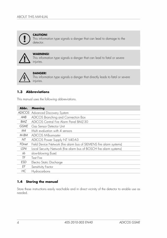
CAUTION!This information type signals a danger that can lead to damage to the detector.
WARNING!This information type signals a danger that can lead to fatal or severeinjuries.
DANGER!This information type signals a danger that directly leads to fatal or severeinjuries.
1.3 Abbreviations
This manual uses the following abbreviations.
Abbr. MeaningADICOS Advanced Discovery System
AAB ADICOS Branching and Connection BoxBMZ ADICOS Central Fire Alarm Panel BMZ-30
GSME Gas Sensor Detector unitM4 Multi evaluation with 4 sensors
M-BM ADICOS M-BusmasterNT ADICOS Power Supply NT V40-A3
FDnet Field Device Network (fire alarm bus of SIEMENS fire alarm systems)LSNi Local Security Network (fire alarm bus of BOSCH fire alarm systems)sb slow-blowing (fuse)TF Test Fire
ESD Electro Static DischargeEF Sensitivity FactorHC Hydrocarbons
1.4 Storing the manual
Store these instructions easily reachable and in direct vicinity of the detector to enable use as needed.
5ADICOS GSME 405-2010-003 EN40
SAFETY INSTRuCTIONS
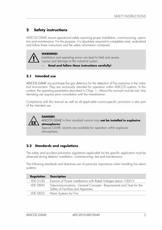
2 Safety instructions
ADICOS GSME ensure operational safety assuming proper installation, commissioning, opera-tion and maintenance. For this purpose, it is absolutely required to completely read, understand and follow these instructions and the safety information contained.
WARNING!Installation and operating errors can lead to fatal and severeinjuries and damage to the industrial system.
− Read and follow these instructions carefully!
2.1 Intended use
ADICOS GSME are point-type fire gas detectors for the detection of fire scenarios in the indus-trial environment. They are exclusively intended for operation within ADICOS systems. In this context, the operating parameters described in Chap. 1, »About this manual« must be met. Any deviating use requires prior consultation with the manufacturer.
Compliance with this manual as well as all applicable country-specific provisions is also part of the intended use.
DANGER!ADICOS GSME in their standard version may not be installed in explosive atmospheres!Special GSME variants are available for operation within explosive atmospheres.
2.2 Standards and regulations
The safety and accident prevention regulations applicable for the specific application must be observed during detector installation, commissioning, test and maintenance.
The following standards and directives are of particular importance when handling fire alarm systems:
Regulation Description
VDE 0100 Erection of Power Installations with Rated Voltages below 1000 VVDE 0800 Telecommunications - General Concepts - Requirements and Tests for the
Safety of Facilities and ApparatusVDE 0833 Alarm Systems for Fire
SAFETY INSTRuCTIONS
6 ADICOS GSME405-2010-003 EN40
Regulation Description
VDE 0845 Protection of Telecommunication Systems Against Lightning, Electrostatic Discharges and Overvoltages From Electric Power Installations - Measures Against Overvoltages
VdS 2095 Guidelines for Automatic Fire Detection and Fire Alarm Systems - Planning and Installation
DIN 14675 Fire Detection and Fire Alarm Systems - Design and OperationDIN EN 54-7 Fire Detection and Fire Alarm Systems - Part 7: Smoke Detectors -
Point Detectors using Scattered Light, Transmitted Light or Ionization
2.3 Personnel qualification
Any work on ADICOS systems may only be performed by qualified personnel. Persons, who can perform work on fire detection and alarm systems and recognize possible dangers based on their professional education, knowledge and experience as well as knowledge of the ap-plicable provisions, are considered qualified persons.
WARNING!Installation, commissioning, parameterization and maintenance may only be performed by authorized and respectively trained personnel!
2.4 Modification
WARNING!Any form of unauthorized modifications or extensions is expressively prohibited!
− In case of doubt, contact the manufacturer!
2.5 Accessories and spare parts
WARNING!Only original spare part and original accessories of the manufacturer may be used!
2.6 Handling outgassing adhesives, sealants and lubricants
CAUTION!Silicone-containing hydrocarbons (siloxanes) damage the surface of the semicon-ductor gas sensors of the ADICOS GSME.
− Do not use any outgassing adhesives, sealants, or lubricants (e.g., silicone) in the surroundings of the detector!
7ADICOS GSME 405-2010-003 EN40
STRuCTuRE
3 Structure
3.1 Overview
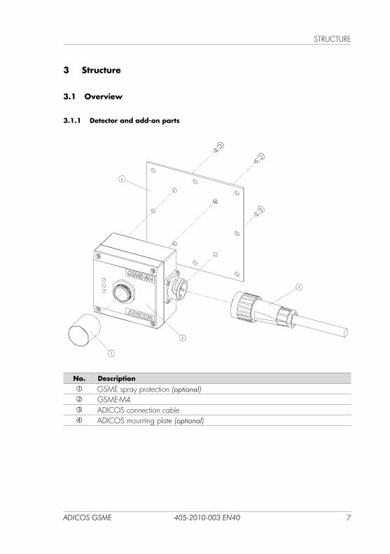
3.1.1 Detector and add-on parts
No. Description GSME spray protection (optional) GSME-M4 ADICOS connection cable ADICOS mounting plate (optional)
100
100 20
98
3236,6
60
71
4
2
1
3
A A
B B
C C
D D
E E
F F
G G
H H
J J
K K
L L
M M
N N
P P
R R
T T
24
24
23
23
22
22
21
21
20
20
19
19
18
18
17
17
16
16
15
15
14
14
13
13
12
12
11
11
10
10
9
9
8
8
7
7
6
6
5
5
4
4
3
3
2
2
1
1
GSME-L4GEWICHT:
A0
BLATT 1 VON 3MASSSTAB:1:1
ZEICHNUNGSNR.
BENENNUNG:
ÄNDERUNGZEICHNUNG NICHT SKALIEREN
WERKSTOFF:
DATUMSIGNATURNAME
ENTGRATENUND SCHARFEKANTENBRECHEN
OBERFLÄCHENGÜTE:WENN NICHT ANDERS DEFINIERT:BEMASSUNGEN SIND IN MILLIMETEROBERFLÄCHENBESCHAFFENHEIT:TOLERANZEN: LINEAR: WINKEL:
QUALITÄT
PRODUKTION
GENEHMIGT
GEPRÜFT
GEZEICHNET
STRuCTuRE
8 ADICOS GSME405-2010-003 EN40
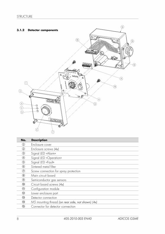
3.1.2 Detector components
No. Description① Enclosure cover② Enclosure screws (4x)③ Signal LED »Alarm«④ Signal LED »Operation«⑤ Signal LED »Fault«⑥ Sintered metal filter⑦ Screw connection for spray protection⑧ Main circuit board⑨ Semiconductor gas sensors⑩ Circuit board screws (4x) ⑪ Configuration module⑫ Lower enclosure part⑬ Detector connection⑭ M5 mounting thread (on rear side, not shown) (4x)⑮ Connector for detector connection
1
2
3
4
5
67
8
10
11
15
12
13
14
9
9ADICOS GSME 405-2010-003 EN40
STRuCTuRE
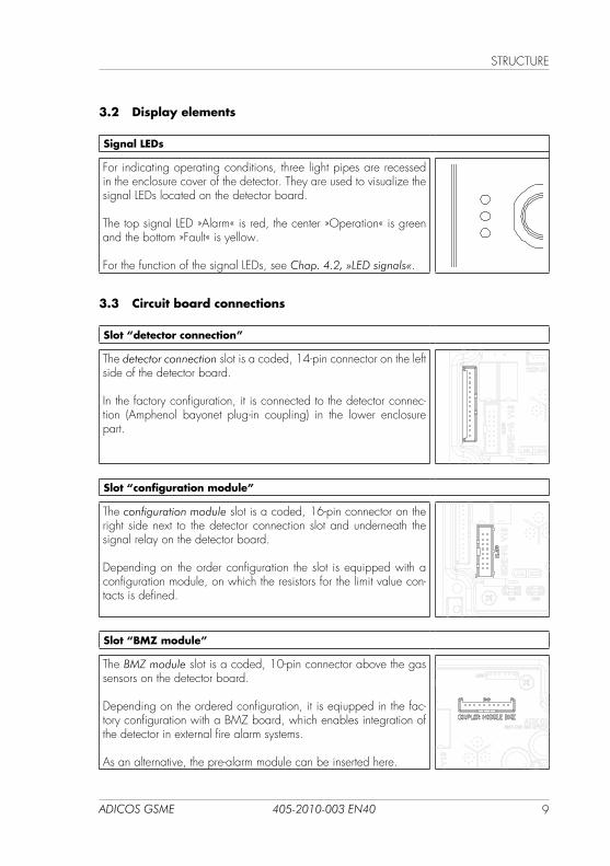
3.2 Display elements
Signal LEDs
For indicating operating conditions, three light pipes are recessed in the enclosure cover of the detector. They are used to visualize the signal LEDs located on the detector board.
The top signal LED »Alarm« is red, the center »Operation« is green and the bottom »Fault« is yellow.
For the function of the signal LEDs, see Chap. 4.2, »LED signals«.
vv
3.3 Circuit board connections
Slot “detector connection”
The detector connection slot is a coded, 14-pin connector on the left side of the detector board.
In the factory configuration, it is connected to the detector connec-tion (Amphenol bayonet plug-in coupling) in the lower enclosure part.
vv
Slot “configuration module”
The configuration module slot is a coded, 16-pin connector on the right side next to the detector connection slot and underneath the signal relay on the detector board.
Depending on the order configuration the slot is equipped with a configuration module, on which the resistors for the limit value con-tacts is defined.
vv
Slot “BMZ module”
The BMZ module slot is a coded, 10-pin connector above the gas sensors on the detector board.
Depending on the ordered configuration, it is eqiupped in the fac-tory configuration with a BMZ board, which enables integration of the detector in external fire alarm systems.
As an alternative, the pre-alarm module can be inserted here.vv
STRuCTuRE
10 ADICOS GSME405-2010-003 EN40
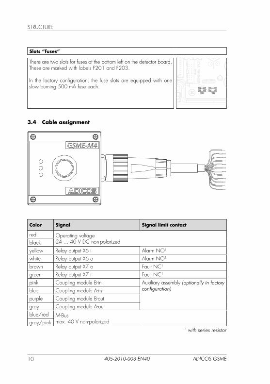
Slots “fuses”
There are two slots for fuses at the bottom left on the detector board. These are marked with labels F201 and F203.
In the factory configuration, the fuse slots are equipped with one slow burning 500 mA fuse each.
vv
3.4 Cable assignment
Color Signal Signal limit contact
red Operating voltage24 ... 40 V DC non-polarizedblack
yellow Relay output X6 i Alarm NO1
white Relay output X6 o Alarm NO1
brown Relay output X7 o Fault NC1
green Relay output X7 i Fault NC1
pink Coupling module B-in Auxiliary assembly (optionally in factory configuration)blue Coupling module A-in
purple Coupling module B-outgray Coupling module A-outblue/red M-Bus
max. 40 V non-polarizedgray/pink1 with series resistor
11ADICOS GSME 405-2010-003 EN40
STRuCTuRE
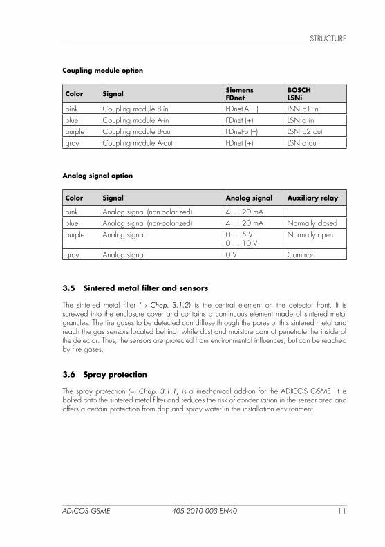
Coupling module option
Color Signal SiemensFDnet
BOSCHLSNi
pink Coupling module B-in FDnet-A (–) LSN b1 inblue Coupling module A-in FDnet (+) LSN a inpurple Coupling module B-out FDnet-B (–) LSN b2 outgray Coupling module A-out FDnet (+) LSN a out
Analog signal option
Color Signal Analog signal Auxiliary relay
pink Analog signal (non-polarized) 4 ... 20 mAblue Analog signal (non-polarized) 4 ... 20 mA Normally closedpurple Analog signal 0 ... 5 V
0 ... 10 VNormally open
gray Analog signal 0 V Common
3.5 Sintered metal filter and sensors
The sintered metal filter (–› Chap. 3.1.2) is the central element on the detector front. It is screwed into the enclosure cover and contains a continuous element made of sintered metal granules. The fire gases to be detected can diffuse through the pores of this sintered metal and reach the gas sensors located behind, while dust and moisture cannot penetrate the inside of the detector. Thus, the sensors are protected from environmental influences, but can be reached by fire gases.
3.6 Spray protection
The spray protection (–› Chap. 3.1.1) is a mechanical add-on for the ADICOS GSME. It is bolted onto the sintered metal filter and reduces the risk of condensation in the sensor area and offers a certain protection from drip and spray water in the installation environment.
FuNCTION
12 ADICOS GSME405-2010-003 EN40
4 Function
During operation, the ADICOS GSME monitors the signals of its gas sensors and triggers an alarm according to the set limit value combinations. If an ADI-COS central unit (ADICOS BMZ-30, ADICOS M-Busmaster) is used, the detector transmits additionally all sensor and operating data to be displayed in the ADICOS service software via M-Bus (–› Chap. 4.5).
If the detector is connected to a central fire alarm panel (ADICOS BMZ-30 or external BMZ), the alarm display of the detector is controlled by the central fire alarm panel.
4.1 Detection
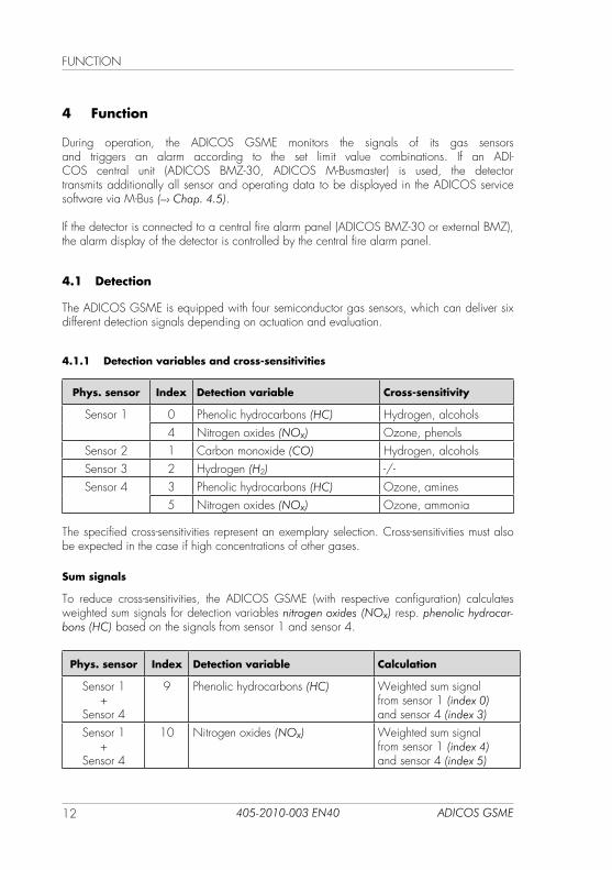
The ADICOS GSME is equipped with four semiconductor gas sensors, which can deliver six different detection signals depending on actuation and evaluation.
4.1.1 Detection variables and cross-sensitivities
Phys. sensor Index Detection variable Cross-sensitivity
Sensor 1 0 Phenolic hydrocarbons (HC) Hydrogen, alcohols4 Nitrogen oxides (NOx) Ozone, phenols
Sensor 2 1 Carbon monoxide (CO) Hydrogen, alcoholsSensor 3 2 Hydrogen (H2) -/-Sensor 4 3 Phenolic hydrocarbons (HC) Ozone, amines
5 Nitrogen oxides (NOx) Ozone, ammonia
The specified cross-sensitivities represent an exemplary selection. Cross-sensitivities must also be expected in the case if high concentrations of other gases.
Sum signals
To reduce cross-sensitivities, the ADICOS GSME (with respective configuration) calculates weighted sum signals for detection variables nitrogen oxides (NOx) resp. phenolic hydrocar-bons (HC) based on the signals from sensor 1 and sensor 4.
Phys. sensor Index Detection variable Calculation
Sensor 1 +
Sensor 4
9 Phenolic hydrocarbons (HC) Weighted sum signal from sensor 1 (index 0) and sensor 4 (index 3)
Sensor 1 +
Sensor 4
10 Nitrogen oxides (NOx) Weighted sum signal from sensor 1 (index 4) and sensor 4 (index 5)
13ADICOS GSME 405-2010-003 EN40
FuNCTION
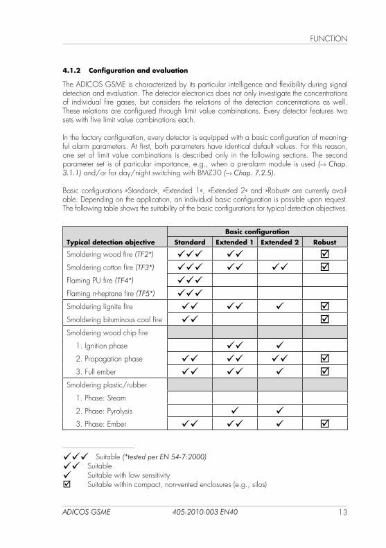
4.1.2 Configuration and evaluation
The ADICOS GSME is characterized by its particular intelligence and flexibility during signal detection and evaluation. The detector electronics does not only investigate the concentrations of individual fire gases, but considers the relations of the detection concentrations as well. These relations are configured through limit value combinations. Every detector features two sets with five limit value combinations each.
In the factory configuration, every detector is equipped with a basic configuration of meaning-ful alarm parameters. At first, both parameters have identical default values. For this reason, one set of limit value combinations is described only in the following sections. The second parameter set is of particular importance, e.g., when a pre-alarm module is used (–› Chap. 3.1.1) and/or for day/night switching with BMZ30 (–› Chap. 7.2.5).
Basic configurations »Standard«, »Extended 1«, »Extended 2« and »Robust« are currently avail-able. Depending on the application, an individual basic configuration is possible upon request. The following table shows the suitability of the basic configurations for typical detection objectives.
Typical detection objective
Basic configuration
Standard Extended 1 Extended 2 Robust
Smoldering wood fire (TF2*) Smoldering cotton fire (TF3*) Flaming Pu fire (TF4*) Flaming n-heptane fire (TF5*) Smoldering lignite fire Smoldering bituminous coal fire Smoldering wood chip fire 1. Ignition phase 2. Propagation phase 3. Full ember Smoldering plastic/rubber
1. Phase: Steam
2. Phase: Pyrolysis 3. Phase: Ember
Suitable (*tested per EN 54-7:2000)
Suitable Suitable with low sensitivity Suitable within compact, non-vented enclosures (e.g., silos)
FuNCTION
14 ADICOS GSME405-2010-003 EN40
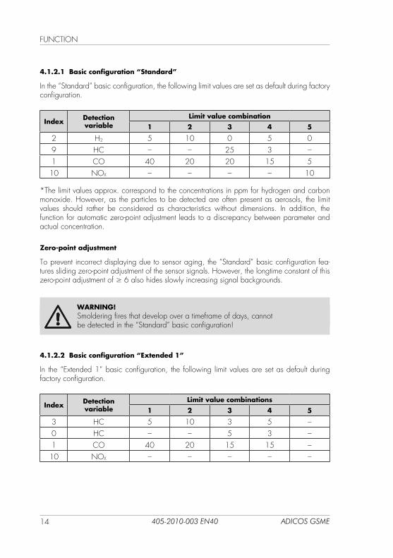
4.1.2.1 Basic configuration “Standard”
In the “Standard” basic configuration, the following limit values are set as default during factory configuration.
Index Detection variable
Limit value combination
1 2 3 4 5
2 H2 5 10 0 5 09 HC – – 25 3 –1 CO 40 20 20 15 5
10 NOX – – – – 10
*The limit values approx. correspond to the concentrations in ppm for hydrogen and carbon monoxide. However, as the particles to be detected are often present as aerosols, the limit values should rather be considered as characteristics without dimensions. In addition, the function for automatic zero-point adjustment leads to a discrepancy between parameter and actual concentration.
Zero-point adjustment
To prevent incorrect displaying due to sensor aging, the “Standard” basic configuration fea-tures sliding zero-point adjustment of the sensor signals. However, the longtime constant of this zero-point adjustment of ≥ 6 also hides slowly increasing signal backgrounds.
WARNING!Smoldering fires that develop over a timeframe of days, cannot be detected in the “Standard” basic configuration!
4.1.2.2 Basic configuration “Extended 1”
In the “Extended 1” basic configuration, the following limit values are set as default during factory configuration.
Index Detection variable
Limit value combinations
1 2 3 4 5
3 HC 5 10 3 5 –0 HC – – 5 3 –1 CO 40 20 15 15 –
10 NOX – – – – –
15ADICOS GSME 405-2010-003 EN40
FuNCTION
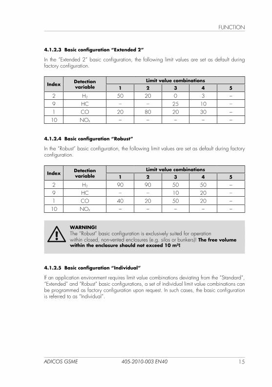
4.1.2.3 Basic configuration “Extended 2”
In the “Extended 2” basic configuration, the following limit values are set as default during factory configuration.
Index Detection variable
Limit value combinations
1 2 3 4 5
2 H2 50 20 0 3 –9 HC – – 25 10 –1 CO 20 80 20 30 –10 NOX – – – – –
4.1.2.4 Basic configuration “Robust”
In the “Robust” basic configuration, the following limit values are set as default during factory configuration.
Index Detection variable
Limit value combinations
1 2 3 4 5
2 H2 90 90 50 50 –9 HC – – 10 20 –1 CO 40 20 50 20 –10 NOX – – – – –
WARNING!The “Robust” basic configuration is exclusively suited for operationwithin closed, non-vented enclosures (e.g. silos or bunkers)! The free volume within the enclosure should not exceed 10 m³!
4.1.2.5 Basic configuration “Individual”
If an application environment requires limit value combinations deviating from the “Standard”, “Extended” and “Robust” basic configurations, a set of individual limit value combinations can be programmed as factory configuration upon request. In such cases, the basic configuration is referred to as “Individual”.
FuNCTION
16 ADICOS GSME405-2010-003 EN40
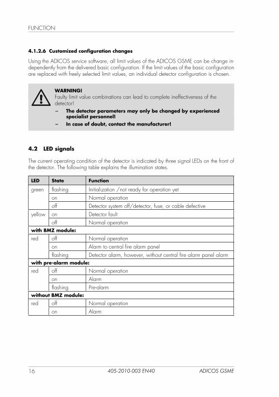
4.1.2.6 Customized configuration changes
using the ADICOS service software, all limit values of the ADICOS GSME can be change in-dependently from the delivered basic configuration. If the limit values of the basic configuration are replaced with freely selected limit values, an individual detector configuration is chosen.
WARNING!Faulty limit value combinations can lead to complete ineffectiveness of the detector!
− The detector parameters may only be changed by experienced specialist personnel!
− In case of doubt, contact the manufacturer!
4.2 LED signals
The current operating condition of the detector is indicated by three signal LEDs on the front of the detector. The following table explains the illumination states.
LED State Function
green flashing Initialization /not ready for operation yeton Normal operationoff Detector system off/detector, fuse, or cable defective
yellow on Detector faultoff Normal operation
with BMZ module:
red off Normal operationon Alarm to central fire alarm panelflashing Detector alarm, however, without central fire alarm panel alarm
with pre-alarm module:
red off Normal operationon Alarmflashing Pre-alarm
without BMZ module:
red off Normal operationon Alarm
17ADICOS GSME 405-2010-003 EN40
FuNCTION
4.3 Signal relays
The ADICOS GSME is equipped with two signal relays that signal the “Alarm” and “Fault” states. The “Alarm” signal relay is realized as normally open contact, the “Fault” signal relay as normally closed contact. The signal lines of the signal relays are integrated into the ADICOS connection cable (–› Chap. 3.4).
4.4 Detector heating
In the factory configuration, the ADICOS GSME is equipped with an integrated heating unit. It heats the detector enclosure and prevents condensation of ambient humidity. Depending on the ordered configuration, it is already activated with the basic configuration of the detector at the factory. During operation, detector heating can be switched on and off via the ADICOS service software. The power consumption of detector heating is up to 10 VA.
In the case of undervoltage, detector heating is switched off automatically. Once the undervolt-age is corrected, heating becomes only active again after a detector reset.
Beyond that, the heating function is limited through enclosure temperature monitoring. If the set highest temperature (default: 40 °C) is exceeded, the heating unit switches off automatically, until the enclosure temperature is lowered again. In the case of a very high ambient tempera-ture and high air humidity, it may thus be necessary to adjust the set limit temperature for the heating function accordingly.
4.5 ADICOS M-Bus
The ADICOS M-Bus is a proprietary two-wire data line, which is used to transfer all detector parameters as well as operating and detection data to the used central unit (ADICOS BMZ-30 / M-Busmaster). This data can be displayed and archived using the ADICOS service software. Beyond that, the parameters of any connected detector can be changed via the ADICOS M-Bus.
The M-Bus lines are integrated into the ADICOS connection cable (–› Chap. 3.4).
INSTALLATION
18 ADICOS GSME405-2010-003 EN40
5 Installation
WARNING!Improper installation of ADICOS detectors can lead to faults and failures of the detector system.
− Installation work may only be performed by specialist personnel! (–› Chap. 2.3, Personnel qualification)
5.1 Installation location
DANGER!ADICOS GSME in their standard version may not be installed inexplosive atmospheres!
− Only use approved GSME variants for operation withinexplosive atmospheres!
WARNING!Arrangement and alignment of ADICOS GSME detectors are highly important for a reliable detection. unfavorable placement can lead to complete ineffectiveness of the detector!
− Only experienced specialist planners may define detector position and alignment!
5.1.1 Protection aspects
The following aspects must be considered when selecting the installation location to ensure fault-free operation of the ADICOS GSME detector.
Temperature
The ambient temperatures at the planned installation location must not exceed and/or undercut the specified temperature range (–› Chap. 10) of the ADICOS GSME detector even in the worst-case scenario. Special attention must be paid to the waste heat of heating-up system components in the surroundings. Intensive solar irradiation should be avoided as well.
Condensation and contamination
The ADICOS GSME detector is basically suited for operation in dust-loaded environments (not in explosive atmospheres). In the case of condensation or permanent contact with damp or oil-containing dusts, the sintered metal filter can be clogged. This reduces the detectivity of the detector and can lead to ineffectiveness. In the case of condensation, detector heating and spray protection must be used. Beyond that, the sintered metal filter must be regularly checked for incrustation.
19ADICOS GSME 405-2010-003 EN40
INSTALLATION
Moisture
If drip or spray water is to be expected in the planned installation environment, direct contact with the sintered metal filter must be prevented. This also applies in the case of regular building cleaning with water. Spray protection must be used in the case of moisture!
Vibration
Strong vibrations can damage the electronics of the ADICOS GSME detector. If strong vibra-tion sources can be found in the surroundings of the planned installation location, the detector must be positioned such that it is protected from vibrations.
Sensor toxins
Silicone-containing hydrocarbons (siloxanes) can oxidize and thus damage the surface of the semiconductor gas sensors of the ADICOS GSME detector. No outgassing adhesives, sealants and lubricants (e.g., silicone) may be used in the surroundings of the detector.
Electromagnetic radiation
Electromagnetic radiation can impact the electronics of the ADICOS GSME detector. Do not mount the detector in the immediate surroundings of power current equipment. use shielded cables only.
5.1.2 Detection aspects
The following aspects must be considered when selecting the installation location to ensure reliable and sensitive operation of the ADICOS GSME detector.
Building geometry and air flow
The way fire gases propagate depends on numerous factors and is far less intuitive as generally assumed. It is thus a particular challenge to ensure that the gas emissions of a smoldering fire reach the sensors of the detector in sufficient concentration within industrial systems with com-plex building geometry, possibly with ventilation systems and machines generating waste heat.
Thus, all influencing factors of the air flow within the building must be considered when defining the installation locations for ADICOS GSME detectors. It may be necessary to perform a fire test at the location of the expected fire source to identify these factors.
False variables
Different false variables can negatively impact the detector function and lead to false alarms and sensor aging. No exhaust gases e.g. from conveyor vehicles or fermentation gases from biological or thermal decomposition must be present at the planned installation location.
INSTALLATION
20 ADICOS GSME405-2010-003 EN40
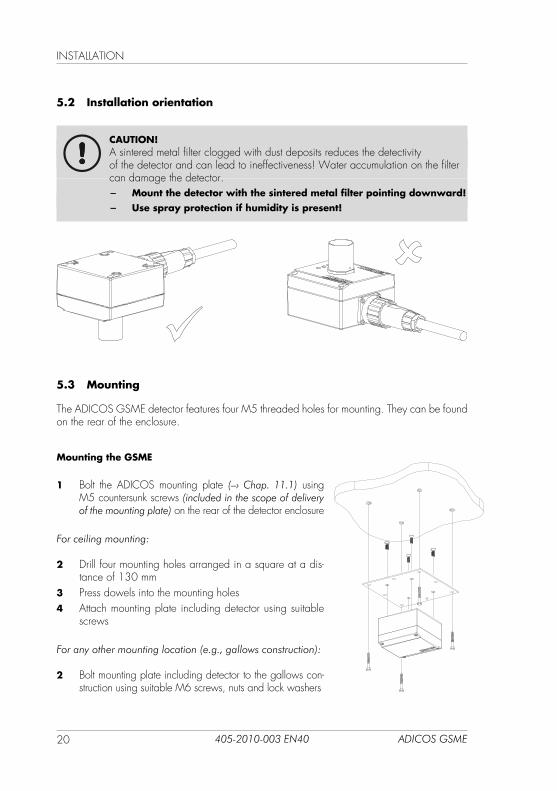
5.2 Installation orientation
CAUTION!A sintered metal filter clogged with dust deposits reduces the detectivityof the detector and can lead to ineffectiveness! Water accumulation on the filter can damage the detector.
− Mount the detector with the sintered metal filter pointing downward! − Use spray protection if humidity is present!
5.3 Mounting
The ADICOS GSME detector features four M5 threaded holes for mounting. They can be found on the rear of the enclosure.
Mounting the GSME
1 Bolt the ADICOS mounting plate (–› Chap. 11.1) using M5 countersunk screws (included in the scope of delivery of the mounting plate) on the rear of the detector enclosure
For ceiling mounting:
2 Drill four mounting holes arranged in a square at a dis-tance of 130 mm
3 Press dowels into the mounting holes4 Attach mounting plate including detector using suitable
screws
For any other mounting location (e.g., gallows construction):
2 Bolt mounting plate including detector to the gallows con-struction using suitable M6 screws, nuts and lock washers
21ADICOS GSME 405-2010-003 EN40
INSTALLATION
5.4 Wiring
WARNING!Improper installation of ADICOS detectors can lead to faults and failures of the detector system.
− Wiring may only be performed by specialist personnel! (–› Chap. 2.3, Personnel qualification)
− De-energize the entire detector system for any wiring! − Use ADICOS connection cables only for connecting detectors
as well as ADICOS branching and connection boxes!
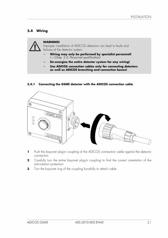
5.4.1 Connecting the GSME detector with the ADICOS connection cable
1 Push the bayonet plug-in coupling of the ADICOS connection cable against the detector connection
2 Carefully turn the entire bayonet plug-in coupling to find the correct orientation of the anti-rotation protection
3 Turn the bayonet ring of the coupling forcefully to attach cable

INSTALLATION
22 ADICOS GSME405-2010-003 EN40
5.4.2 Connecting the ADICOS connection cable with the ADICOS AAB
Depending on the system and detector configuration, the specific wiring of the ADICOS con-nection cable and the ADICOS branching and connection box (ADICOS AAB) varies. The following procedure applies for all wiring variants.
Wiring the ADICOS AAB
1 Open the enclosure cover of the ADICOS AAB2 Open the lower cable gland of the ADICOS AAB3 Route the ADICOS connection cable through the lower cable gland into the ADICOS AAB4 Connect the wires to the connection terminals of the ADICOS AAB according to the
wiring diagram5 Close the cable gland of the ADICOS AAB6 Close the enclosure cover of the ADICOS AAB
NOTE!Further information on the installation of the ADICOS branching and connection box can be found in GTE instructions no. 430-2410-001!
A
A
23ADICOS GSME 405-2010-003 EN40
INSTALLATION
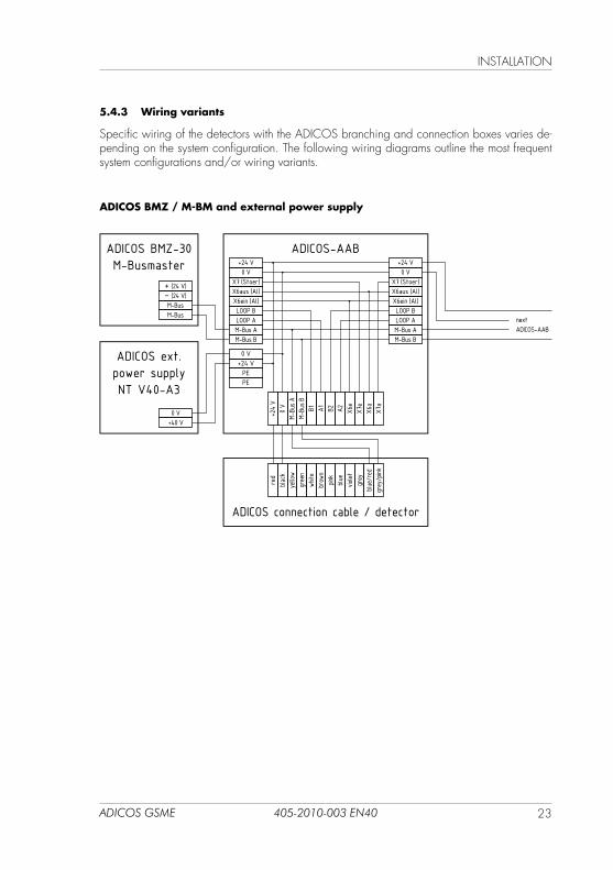
5.4.3 Wiring variants
Specific wiring of the detectors with the ADICOS branching and connection boxes varies de-pending on the system configuration. The following wiring diagrams outline the most frequent system configurations and/or wiring variants.
ADICOS BMZ / M-BM and external power supply
+24 V
0 V
M-Bu
s AM-
Bus B
B1 A1 B2 A2 X6e
X7e
X6a
X7a
red
blac
kye
llow
gree
nwh
itebrow
npin
kblu
evio
letgrey
blue/
red
grey
/pink
0 V+24 VPEPE
+24 V0 V
X7 (Stoer)X6aus (Al)X6ein (Al)LOOP BLOOP AM-Bus AM-Bus B
+24 V0 V
X7 (Stoer)X6aus (Al)X6ein (Al)LOOP BLOOP AM-Bus AM-Bus B
ADICOS-AAB
ADICOS ext.power supplyNT V40-A3
0 V+40 V
ADICOS BMZ-30M-Busmaster
+ (24 V)− (24 V)M-BusM-Bus
ADICOS connection cable / detector
nextADICOS-AAB
INSTALLATION
24 ADICOS GSME405-2010-003 EN40
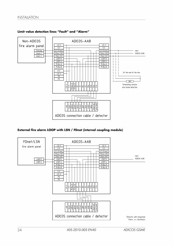
Limit value detection lines “Fault” and “Alarm”
External fire alarm LOOP with LSN / FDnet (internal coupling module)
+24 V
0 V
M-Bu
s AM-
Bus B
B1 A1 B2 A2 X6e
X7e
X6a
X7a
0 V+24 VPEPE
+24 V0 V
X7 (Stoer)X6aus (Al)X6ein (Al)LOOP BLOOP AM-Bus AM-Bus B
+24 V0 V
X7 (Stoer)X6aus (Al)X6ein (Al)LOOP BLOOP AM-Bus AM-Bus B
ADICOS-AAB
Terminating resistorwire break detection
3k3
Non-ADICOSfire alarm panel
StörungAlarm 1Alarm 2
At the end of the line:
ADICOS connection cable / detector
nextADICOS-AAB
red
blac
kye
llow
gree
nwh
itebrow
npin
kblu
evio
letgrey
blue/
red
grey
/pink
+24 V
0 V
M-Bu
s AM-
Bus B
B1 A1 B2 A2 X6e
X7e
X6a
X7a
0 V+24 VPEPE
+24 V0 V
X7 (Stoer)X6aus (Al)X6ein (Al)LOOP BLOOP AM-Bus AM-Bus B
+24 V0 V
X7 (Stoer)X6aus (Al)X6ein (Al)LOOP BLOOP AM-Bus AM-Bus B
ADICOS-AAB
*Detector with integratedFDnet- or LSN-Module
FDnet/LSNfire alarm panel
LOOP BLOOP A
ADICOS connection cable / detector
nextADICOS-AAB
red
blac
kye
llow
gree
nwh
itebrow
npin
kblu
evio
letgrey
blue/
red
grey
/pink
25ADICOS GSME 405-2010-003 EN40
INSTALLATION
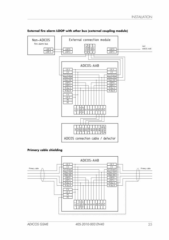
External fire alarm LOOP with other bus (external coupling module)
Primary cable shielding
+24 V
0 V
M-Bu
s AM-
Bus B
B1 A1 B2 A2 X6e
X7e
X6a
X7a
0 V+24 VPEPE
+24 V0 V
X7 (Stoer)X6aus (Al)X6ein (Al)LOOP BLOOP AM-Bus AM-Bus B
+24 V0 V
X7 (Stoer)X6aus (Al)X6ein (Al)LOOP BLOOP AM-Bus AM-Bus B
ADICOS-AAB
LOOP BLOOP A
LOOP BLOOP ASt
örun
g 1
Störun
g 2
Alarm
1Alarm
2
External connection moduleNon-ADICOSfire alarm bus
LOOP BLOOP A
ADICOS connection cable / detector
nextADICOS-AAB
red
blac
kye
llow
gree
nwh
itebrow
npin
kblu
evio
letgrey
blue/
red
grey
/pink
+24 V
0 V
M-Bu
s AM-
Bus B
B1 A1 B2 A2 X6e
X7e
X6a
X7a
0 V+24 VPEPE
+24 V0 V
X7 (Stoer)X6aus (Al)X6ein (Al)LOOP BLOOP AM-Bus AM-Bus B
+24 V0 V
X7 (Stoer)X6aus (Al)X6ein (Al)LOOP BLOOP AM-Bus AM-Bus B
ADICOS-AAB
Primary cable Primary cable
INSTALLATION
26 ADICOS GSME405-2010-003 EN40
5.5 Retrofitting of BMZ modules
WARNING!De-energize the entire detector system for any wiring and secure against unintentional reactivation!
WARNING!Detector electronics and BMZ modules are sensitive assemblies, which can be damaged on contact due to electrostatic discharge.
− Apply ESD measures when working on the detector electronics! − Do not touch electronic components!
The electronics of the ADICOS GSME features a slot for BMZ modules. Depending on the ordered configuration, the detector electronics is populated with the necessary module in the factory configuration. However, BMZ module retrofits are required on site in special cases.In addition to the electrical installation, it must be observed that a configuration change of the detector using the ADICOS service software is usually also required to use the module functionalities.
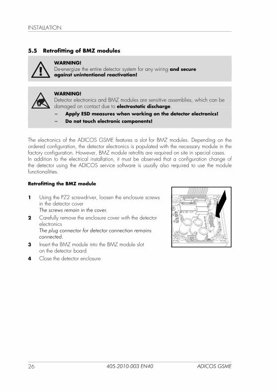
Retrofitting the BMZ module
1 using the PZ2 screwdriver, loosen the enclosure screws in the detector cover The screws remain in the cover.
2 Carefully remove the enclosure cover with the detector electronics The plug connector for detector connection remains connected.
3 Insert the BMZ module into the BMZ module slot on the detector board
4 Close the detector enclosure
27ADICOS GSME 405-2010-003 EN40
INSTALLATION
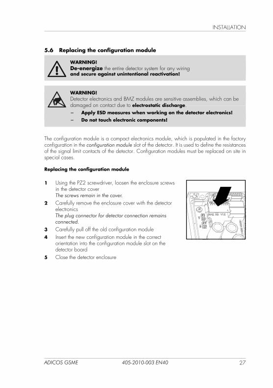
5.6 Replacing the configuration module
WARNING!De-energize the entire detector system for any wiring and secure against unintentional reactivation!
WARNING!Detector electronics and BMZ modules are sensitive assemblies, which can be damaged on contact due to electrostatic discharge.
− Apply ESD measures when working on the detector electronics! − Do not touch electronic components!
The configuration module is a compact electronics module, which is populated in the factory configuration in the configuration module slot of the detector. It is used to define the resistances of the signal limit contacts of the detector. Configuration modules must be replaced on site in special cases.
Replacing the configuration module
1 using the PZ2 screwdriver, loosen the enclosure screws in the detector cover The screws remain in the cover.
2 Carefully remove the enclosure cover with the detector electronics The plug connector for detector connection remains connected.
3 Carefully pull off the old configuration module4 Insert the new configuration module in the correct
orientation into the configuration module slot on the detector board
5 Close the detector enclosure
COMMISSIONING
28 ADICOS GSME405-2010-003 EN40
6 Commissioning
DANGER!ADICOS systems work with electricity that may lead to system damage and fire in the case of improper installation.
− Prior to switching on, check that all detectors are properlymounted and wired!
− Commissioning may only be performed by qualified specialist personnel!
WARNING!The protection class of the ADICOS detectors indicated in the technical data is only ensured with a fully closed enclosure cover. onimproperly closed detector can lead to false alarms and failure.
− Prior to commissioning, make sure that all detectors of thesystem are fully closed!
NOTE!ADICOS detectors must not be commissioned individually. With commissioning of the central unit of the ADICOS system, all detectors start upautomatically.
NOTE!The ADICOS GSME remain in fault, until the start-up process is completed.
► Commission the ADICOS system per the instructions of the used central unit (ADICOS BMZ-30 / M-Busmaster)
Z The approx. 5-minute start-up process starts automatically.
Z The green signal LED »Operation« flashes.
Z The yellow signal LED »Fault« illuminates continuously. The detector remains in fault, until the end of the start-up process.
Z The detector electronics is initiated and all sensors are sub-sequently heated to operating temperature.
Z Once the start-up process is completed, the signal LED »Operation« illuminates green continuously and the yellow signal LED »Fault« goes out.
29ADICOS GSME 405-2010-003 EN40
OPERATION
7 Operation
During operation, the detector monitors the fire gas concentrations captured by the sensors per its basic configuration and triggers an alarm, when the set alarm limit values are exceeded. The query interval of the sensors amounts to 30 seconds.
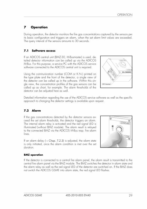
7.1 Software access
If an ADICOS central unit (BMZ-30, M-Busmaster) is used, de-tailed detector information can be called up via the ADICOS M-Bus. For this purpose, a service PC with the ADICOS service software connected to the ADICOS central unit is required.
using the communication number (COM or K.N.) printed on the type plate and the front of the detector, a single view of the detector can be called up in the software. Within this sin-gle view, the concentration profiles of the gas sensors can be called up as chart, for example. The alarm thresholds of the detector can be adjusted here as well.
Detailed information regarding the use of the ADICOS service software as well as the specific approach to changing the detector settings is available upon request.
7.2 Alarm
If the gas concentrations detected by the detector sensors ex-ceed the set alarm thresholds, the detector triggers an alarm. The internal alarm relay is activated and the red signal LED is illuminated (without BMZ module). The alarm result is relayed to the connected BMZ via the ADICOS M-Bus resp. fire alarm lines.
If an alarm delay (–› Chap. 7.2.3) is adjusted, the alarm state is only initiated, once the alarm condition is met over the set duration.
BMZ operation
If the detector is connected to a central fire alarm panel, the alarm result is transmitted to the central fire alarm panel via the BMZ module. The BMZ switches the detector in alarm state and the alarm relay as well as the red signal LED of the detector are switched on. If the BMZ does not switch the ADICOS GSME into alarm state, the red signal LED flashes.
GSME-M
4G000001
20...40 / 14
408-2001-201
2 x 0,5 A
64
2017
G0000001
GTE Industrieelektronik GmbH
Advanced Discovery System
TYPEANRCOM
SERIAL
YRIP
VDC / VA
IS ≤
°C-20
≤ T
a ≤ 50
COM-Nummer
OPERATION
30 ADICOS GSME405-2010-003 EN40
7.2.1 Resetting the alarm
The ADICOS GSME remains in alarm state, as long as the alarm condition is met. The state is newly determined in every query cycle (30 seconds interval). As soon as the alarm condition is not met, the alarm state is automatically reset. Signal LED »Alarm« is only reset after a respective delay, if an alarm holding time (–› Chap. 7.2.2) is set.
If the alarm LED is controlled via central fire alarm panel, the alarm state can be reset via the alarm reset contact of the BMZ. Beyond that, an alarm can only be reset via a detector reset, which is expressly discouraged.
7.2.2 Alarm holding time
The alarm holding time is an optional parameter that can be adjusted via the ADICOS service software. If set, the signal LED »Alarm« is only reset after a respective delay after the alarm con-dition is not met anymore. By default, the alarm holding time amounts to approx. 7.5 minutes.
7.2.3 Alarm delay
The alarm delay is an optional parameter that can be adjusted via the ADICOS service soft-ware. If set, the alarm state is only triggered, if the alarm condition is met over the set minimum timeframe (in minutes).
WARNING!Faulty parameterization of the alarm delay function can lead to ineffectiveness of the detector!
− The detector parameters may only be changed by experienced specialist personnel!
− In case of doubt, contact the manufacturer!
7.2.4 Pre-alarm
If the ADICOS GSME is equipped with a pre-alarm module and respectively configured, set 2 of the stored limit value combinations (–› Chap. 4.1) is automatically evaluated as trigger criterion for the pre-alarm. If the limit values from set 2 are exceeded, the pre-alarm module relay switches and the red signal LED »Alarm« flashes.
7.2.5 Day/night switching
If the ADICOS GSME is operated together with an ADICOS BMZ30, the day/night switching function can be used. If respectively parameterized via the ADICOS service software, the alarm evaluation then considers set 1 of the stored limit value combinations during day operation and set 2 during night operation only. This way, different alarm thresholds can be monitored by day and night. This is for example helpful, if interference due to vehicle exhausts or similar must be expected by day, which should not lead to an alarm.
31ADICOS GSME 405-2010-003 EN40
MAINTENANCE
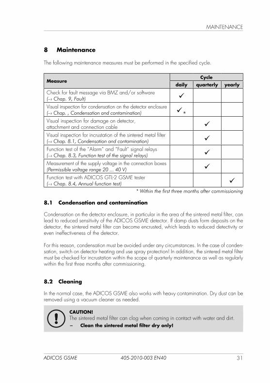
8 Maintenance
The following maintenance measures must be performed in the specified cycle.
MeasureCycle
daily quarterly yearly
Check for fault message via BMZ and/or software(–› Chap. 9, Fault)
Visual inspection for condensation on the detector enclosure (–› Chap. , Condensation and contamination) *Visual inspection for damage on detector, attachment and connection cable Visual inspection for incrustation of the sintered metal filter (–› Chap. 8.1, Condensation and contamination) Function test of the “Alarm” and “Fault” signal relays(–› Chap. 8.3, Function test of the signal relays) Measurement of the supply voltage in the connection boxes (Permissible voltage range 20 ... 40 V) Function test with ADICOS GTL-2 GSME tester (–› Chap. 8.4, Annual function test)
* Within the first three months after commissioning
8.1 Condensation and contamination
Condensation on the detector enclosure, in particular in the area of the sintered metal filter, can lead to reduced sensitivity of the ADICOS GSME detector. If damp dusts form deposits on the detector, the sintered metal filter can become encrusted, which leads to reduced detectivity or even ineffectiveness of the detector.
For this reason, condensation must be avoided under any circumstances. In the case of conden-sation, switch on detector heating and use spray protection! In addition, the sintered metal filter must be checked for incrustation within the scope of quarterly maintenance as well as regularly within the first three months after commissioning.
8.2 Cleaning
In the normal case, the ADICOS GSME also works with heavy contamination. Dry dust can be removed using a vacuum cleaner as needed.
CAUTION!The sintered metal filter can clog when coming in contact with water and dirt.
− Clean the sintered metal filter dry only!
MAINTENANCE
32 ADICOS GSME405-2010-003 EN40
8.3 Function test of the signal relays
The “Alarm” and “Fault” signal relays must be checked for function quarterly. For this purpose, they can be switched for test purposes via the ADICOS service software.
NOTE!The function test of the signal relays triggers an alarm resp. fault state in the connected central fire alarm panel.
− Switch the BMZ into inspection mode prior to the function test!
8.4 Annual function test
CAUTION!To ensure correct function of the detector, a test with the ADICOS GTL-2 tester is required.
− Perform at least one test triggering per year with the GTL-2! − Observe GTE instructions no. 430-2410-101!
NOTE!The function test of the detector triggers an alarm state in the connected central fire alarm panel.
− Switch the BMZ into inspection mode prior to the function test!
8.5 Detector replacement
The maximum service life of the sensors of the ADICOS GSME detector is limited to eight years. Depending on the aggressiveness of the usage environment, the sensitivity of the sensor can also decline earlier and make a detector replacement necessary.
CAUTION!Replace ADICOS GSME detectors no later than eight years after commissioning!
The same information apply to detector replacement like for their initial installation (–› Chap. 5, Installation).
33ADICOS GSME 405-2010-003 EN40
FAuLT
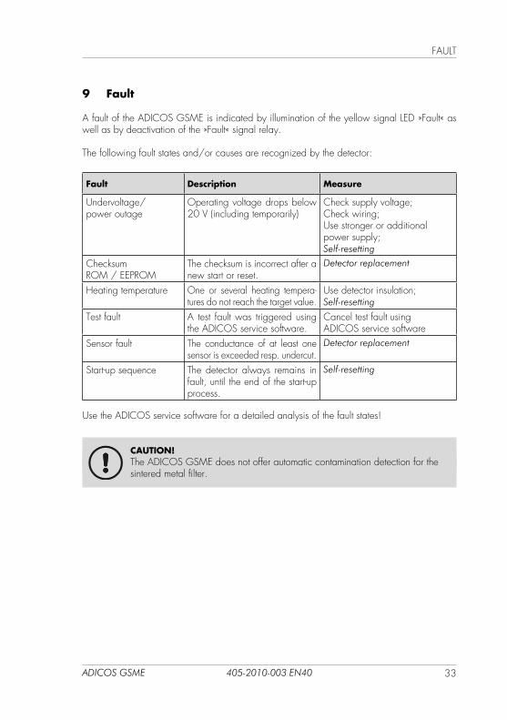
9 Fault
A fault of the ADICOS GSME is indicated by illumination of the yellow signal LED »Fault« as well as by deactivation of the »Fault« signal relay.
The following fault states and/or causes are recognized by the detector:
Fault Description Measure
undervoltage/power outage
Operating voltage drops below 20 V (including temporarily)
Check supply voltage;Check wiring;use stronger or additional power supply;Self-resetting
Checksum ROM / EEPROM
The checksum is incorrect after a new start or reset.
Detector replacement
Heating temperature One or several heating tempera-tures do not reach the target value.
use detector insulation;Self-resetting
Test fault A test fault was triggered using the ADICOS service software.
Cancel test fault using ADICOS service software
Sensor fault The conductance of at least one sensor is exceeded resp. undercut.
Detector replacement
Start-up sequence The detector always remains in fault, until the end of the start-up process.
Self-resetting
use the ADICOS service software for a detailed analysis of the fault states!
CAUTION!The ADICOS GSME does not offer automatic contamination detection for the sintered metal filter.
TECHNICAL DATA
34 ADICOS GSME405-2010-003 EN40
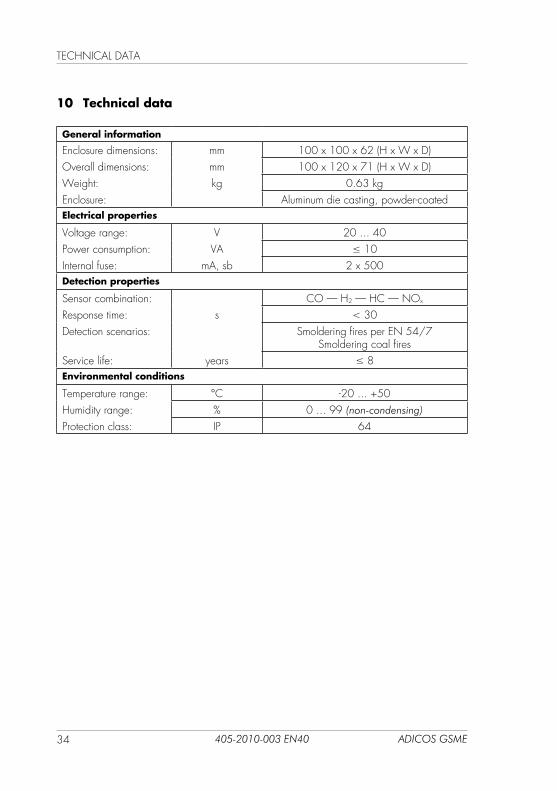
10 Technical data
General information
Enclosure dimensions: mm 100 x 100 x 62 (H x W x D)Overall dimensions: mm 100 x 120 x 71 (H x W x D)Weight: kg 0.63 kgEnclosure: Aluminum die casting, powder-coatedElectrical properties
Voltage range: V 20 ... 40Power consumption: VA ≤ 10Internal fuse: mA, sb 2 x 500Detection properties
Sensor combination: CO — H2 — HC — NOx
Response time: s < 30Detection scenarios: Smoldering fires per EN 54/7
Smoldering coal firesService life: years ≤ 8Environmental conditions
Temperature range: °C -20 ... +50Humidity range: % 0 ... 99 (non-condensing)
Protection class: IP 64
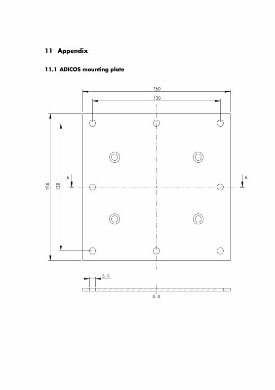
11 Appendix
11.1 ADICOS mounting plate
A A
150
150
130
130
6,4
A-A