Adhesive Bond Process Qualification Protocols Development & Development of … · 2019-06-03 ·...
87
Adhesive Bond Process Qualification Protocols Development & Development of Roadmap for Bonded Structure Certification Waruna Seneviratne, John Tomblin, and Upul Palliyaguru 2019Technical Review - (05/22/2019)
Transcript of Adhesive Bond Process Qualification Protocols Development & Development of … · 2019-06-03 ·...

Adhesive Bond Process Qualification Protocols Development & Development of Roadmap for Bonded Structure Certification
Waruna Seneviratne, John Tomblin, and Upul Palliyaguru
2019Technical Review - (05/22/2019)

2
Adhesive Bond Process Qualification Protocols Development & Development of Roadmap for Bonded Structure Certification
• Principal Investigators & Researchers
• John Tomblin, PhD, and Waruna Seneviratne, PhD
• Upul Palliyaguru and Anushi Amaranayake
• FAA Technical Monitor
• Ahmet Oztekin
• Other FAA/CMH-17 Personnel Involved
• Larry Ilcewicz, PhD, Cindy Ashforth, and Curtis Davies,
• DoD & Industry Participation
• AFRL, Boeing, Bell Helicopter, Henkel, Honda Aircraft Co., Lockheed Martin, MMM, MTech Engineering Services, NAVAIR, Solvey Industries , Textron Aviation, Boom Aerospace

Adhesive Bond Process Qualification Protocols Development (Background)
• Aircraft companies tend to use bonded joins in their primary structure due to various time and cost savings. However, qualification of the bond process and certification of the bonded structure requires extensive amount of substantiation work.
• Due to the complexity and numerous variables seen in a bond system, locking on to a these parameters needs extensive exploration of all possible variations in the bond process. After locking onto this processes, effective and efficient methods for quality assurance needs to be implemented to qualify the bonding process.
• After the bond process qualification tasks are completed, bonded structure needs to be certified per the requirements of the safety agencies.
3
The Primary goal of this research program is to develop a road map for qualification activities of a bond system and support development of certification road map for bonded structures per the safety requirements through substantiation.
Substrate
Metal Composites
Surface Preparation
Degreasing Abrasion Chemical Treatment
Can be combined
Type
Primer
Bond Process Qualification[Critical Factors]
Surface PreparationMaterial & Process
Variability (Material Qualification)
Pre-Bond Surface Characterization
Adhesive
Material Batch Variability Process Variability History Quality
Paste Film
Mixing(for Paste)
Adhesive Application Bondline Thickness Control Cure Environment Effects of Defects
TgViscosity
Shelf lifeStorage lifeOuttime
TemperatureHumidityField Repair Conditions
Multiple Cure OptionsTooling CTE MismatchTemperature ControlsRamp Rate(s)Pressure
Application MethodOpen Time
(ex., Amine Blush)
Paste Film
Pre-Mixed Glass BeadsGlass Bead Mixing into
Adhesive Mix
Knit Random Mat
Unsupported
Application side(s)ApplicatorPreheat SubstratePreheat AdhesiveAdhesive Fillets
TolerancesVacuum or notMixing Technique
Scrim ClothMicro Beads Mixed into
Adhesive
X-Ray Photoelectron Spectroscopy
Fourier Transform IR Spectroscopy (FTIR)
Sessile Drop Contact Angle (CA)
Grit Blasting Hand Sanding Peel-Ply RemovalPlasma (Ionized Gas)
Treatment
Applicator Mix RatioMixing Technique
Adhesive Bond Process Qualification Protocols Development (Road Map)
4
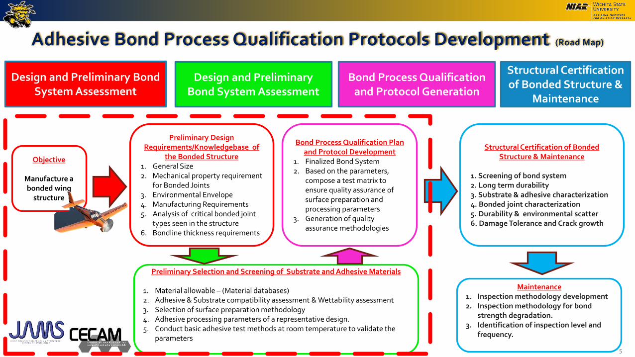
Objective
Manufacture a bonded wing
structure
Preliminary Design Requirements/Knowledgebase of
the Bonded Structure1. General Size2. Mechanical property requirement
for Bonded Joints3. Environmental Envelope 4. Manufacturing Requirements5. Analysis of critical bonded joint
types seen in the structure6. Bondline thickness requirements
Preliminary Selection and Screening of Substrate and Adhesive Materials
1. Material allowable – (Material databases)2. Adhesive & Substrate compatibility assessment & Wettability assessment3. Selection of surface preparation methodology4. Adhesive processing parameters of a representative design.5. Conduct basic adhesive test methods at room temperature to validate the
parameters
Bond Process Qualification Plan and Protocol Development
1. Finalized Bond System2. Based on the parameters,
compose a test matrix to ensure quality assurance of surface preparation and processing parameters
3. Generation of quality assurance methodologies
Design and Preliminary Bond System Assessment
Design and Preliminary Bond System Assessment
Bond Process Qualification and Protocol Generation
Structural Certification of Bonded Structure &
Maintenance
Structural Certification of Bonded Structure & Maintenance
1. Screening of bond system2. Long term durability3. Substrate & adhesive characterization4. Bonded joint characterization5. Durability & environmental scatter 6. Damage Tolerance and Crack growth
Maintenance1. Inspection methodology development 2. Inspection methodology for bond
strength degradation.3. Identification of inspection level and
frequency.
Adhesive Bond Process Qualification Protocols Development (Road Map)
5
Objective
Manufacture a bonded wing
structure
Preliminary Design Requirements/Knowledgebase of
the Bonded Structure1. General Size2. Mechanical property requirement
for Bonded Joints3. Environmental Envelope 4. Manufacturing Requirements5. Analysis of critical bonded joint
types seen in the structure6. Bondline thickness requirements
Preliminary Selection and Screening of Substrate and Adhesive Materials
1. Material allowable – (Material databases)2. Adhesive & Substrate compatibility assessment & Wettability assessment3. Selection of surface preparation methodology4. Adhesive processing parameters of a representative design.5. Conduct basic adhesive test methods at room temperature to validate the
parameters
Bond Process Qualification Plan and Protocol Development
1. Finalized Bond System2. Based on the parameters,
compose a test matrix to ensure quality assurance of surface preparation and processing parameters
3. Generation of quality assurance methodologies
Design and Preliminary Bond System Assessment
Design and Preliminary Bond System Assessment
Bond Process Qualification and Protocol Generation
Structural Certification of Bonded Structure &
Maintenance
Structural Certification of Bonded Structure & Maintenance
1. Screening of bond system2. Long term durability3. Substrate & adhesive characterization4. Bonded joint characterization5. Durability & environmental scatter 6. Damage Tolerance and Crack growth
Maintenance1. Inspection methodology development 2. Inspection methodology for bond
strength degradation.3. Identification of inspection level and
frequency.

Overview of the Presentation
• Preliminary screening and down-selection of adhesive-substrate combinations
• Critical parameters in the surface preparation
• Surface preparation methodology
• Quality assurance and handling of prepared substrates
• Critical parameters in the adhesive application and cure process
• Adhesive handling guidelines
• Mixing and application
• Bondline thickness control
• Bond process qualification protocols generation to asses the effect of varying the parameters
6
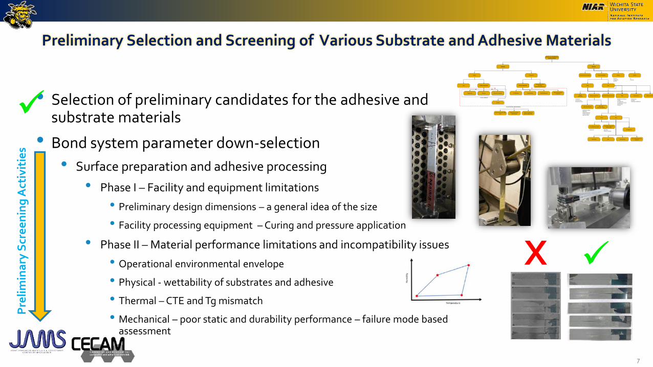
Preliminary Selection and Screening of Various Substrate and Adhesive Materials
• Selection of preliminary candidates for the adhesive and substrate materials
• Bond system parameter down-selection
• Surface preparation and adhesive processing
• Phase I – Facility and equipment limitations
• Preliminary design dimensions – a general idea of the size
• Facility processing equipment – Curing and pressure application
• Phase II – Material performance limitations and incompatibility issues
• Operational environmental envelope
• Physical - wettability of substrates and adhesive
• Thermal – CTE and Tg mismatch
• Mechanical – poor static and durability performance – failure mode based assessment
7
Pre
lim
ina
ry S
cre
en
ing
Act
ivit
ies
Substrate
Metal Composites
Surface Preparation
Degreasing Abrasion Chemical Treatment
Can be combined
Type
Primer
Bond Process Qualification[Critical Factors]
Surface PreparationMaterial & Process
Variability (Material Qualification)
Pre-Bond Surface Characterization
Adhesive
Material Batch Variability Process Variability History Quality
Paste Film
Mixing(for Paste)
Adhesive Application Bondline Thickness Control Cure Environment Effects of Defects
TgViscosity
Shelf lifeStorage lifeOuttime
TemperatureHumidityField Repair Conditions
Multiple Cure OptionsTooling CTE MismatchTemperature ControlsRamp Rate(s)Pressure
Application MethodOpen Time
(ex., Amine Blush)
Paste Film
Pre-Mixed Glass BeadsGlass Bead Mixing into
Adhesive Mix
Knit Random Mat
Unsupported
Application side(s)ApplicatorPreheat SubstratePreheat AdhesiveAdhesive Fillets
TolerancesVacuum or notMixing Technique
Scrim ClothMicro Beads Mixed into
Adhesive
X-Ray Photoelectron Spectroscopy
Fourier Transform IR Spectroscopy (FTIR)
Sessile Drop Contact Angle (CA)
Grit Blasting Hand Sanding Peel-Ply RemovalPlasma (Ionized Gas)
Treatment
Applicator Mix RatioMixing Technique
X
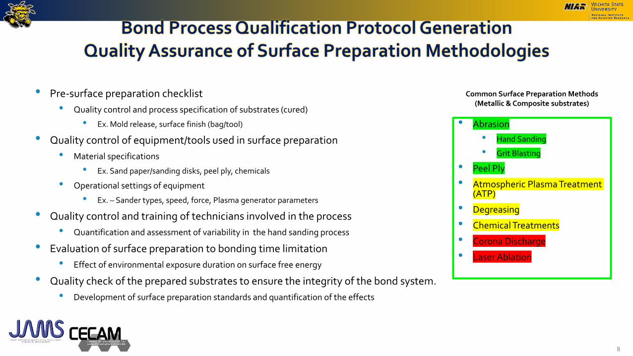
Bond Process Qualification Protocol GenerationQuality Assurance of Surface Preparation Methodologies
• Abrasion
• Hand Sanding
• Grit Blasting
• Peel Ply
• Atmospheric Plasma Treatment (ATP)
• Degreasing
• Chemical Treatments
• Corona Discharge
• Laser Ablation
8
Common Surface Preparation Methods(Metallic & Composite substrates)
• Pre-surface preparation checklist
• Quality control and process specification of substrates (cured)
• Ex. Mold release, surface finish (bag/tool)
• Quality control of equipment/tools used in surface preparation
• Material specifications
• Ex. Sand paper/sanding disks, peel ply, chemicals
• Operational settings of equipment
• Ex. – Sander types, speed, force, Plasma generator parameters
• Quality control and training of technicians involved in the process
• Quantification and assessment of variability in the hand sanding process
• Evaluation of surface preparation to bonding time limitation
• Effect of environmental exposure duration on surface free energy
• Quality check of the prepared substrates to ensure the integrity of the bond system.
• Development of surface preparation standards and quantification of the effects

Bond Process Qualification Protocol GenerationQuality Assurance Standard Development
• Surface Preparation
• Goal – Increase the surface free energy -> better wettability -> good bonds
• Method of verification -> Water contact angle measurement
• Quality check -> Water contact angle measurement comparison to a known standard
• Equipment used – Surface Analysts – BTG Labs
• Contact angle measurements validated with Goniometer results.
• Surface preparation quality assurance standard
• Utilizing different abrasion methods (pressures/grit size) – obtain a range of different surface free energies (contact angles)
• Fabricate bonded joint specimen and evaluate the bond strength
9
59o
65o
63o
64o
58o
62o
60o
63o
55o
62o
58o
60o
55o
62o
57o
59o
Surface Analyst Goniometer
Surface Analyst Goniometer
0123456789
101112131415161718192021222324252627282930313233343536373839404142434445464748495051525354555657585960616263646566676869
Point 1 Point 2 Point 3 Point 4 Point 5 Point 6 Point 7 Point 8 Point 9 Point 10 Point 11 Point 12 Point 13 Point 14 Point 15 Point 16
An
gle
[d
egre
es]
Surface Analyst Goniometer
± 2 variation

0
1000
2000
3000
4000
5000
6000
7000
20 30 40 50 60 70 80 90 100
Bo
nd
Str
eng
th [
psi
]
Quality Assurance of Surface Preparation – FM300-2M
10
Substrate - T800/3900-2 Adhesive – FM300-2M
Surface Preparation – MultipleTest Method – D3165
Cohesion/First PlyHigh Adhesion/Low
CohesionAdhesion
51o
54o
55o
54o
53o
51o
52o
51o
63o
58o
58o
60o
59o
56o
59o
60o
57o
57o
58o
57o
59o
57o
57o
55o
56o
58o
55o
54o
53o
50o
53o
56o

Quality Assurance of Surface Preparation – EA9394
11
0
500
1000
1500
2000
2500
3000
3500
4000
4500
5000
25 35 45 55 65 75 85 95
Bo
nd
Str
eng
th [
psi
]
Average Water Contact Angle [degrees]
Substrate - T800/3900-2 Adhesive – EA9394
Surface Preparation – MultipleTest Method – D3165
Cohesion/First Ply Adhesion
37 44 64 73 93

Environmental Exposure Effects of Prepared Substrates
12
25
30
35
40
45
50
55
60
65
0 200 400 600 800 1000 1200
Co
nta
ct A
ng
le [
deg
rees
]
Time [mins]
Substrate 1 Substrate 2
Substrate - T800/3900-2 Surface Preparation – Manual 120G

0
10
20
30
40
50
60
1 2 3 4 5
Co
nta
ct A
ng
le [
deg
rees
]
Technician
Surface Preparation - Hand Abrasion Technician Process Variation
13
Substrate - T650/5320-1Surface Preparation – Manual Abrasion 120G
51o
54o
55o
54o
53o
51o
52o
51o
63o
58o
58o
60o
59o
56o
59o
60o
57o
57o
58o
57o
59o
57o
57o
55o
56o
58o
55o
54o
53o
50o
53o
56o
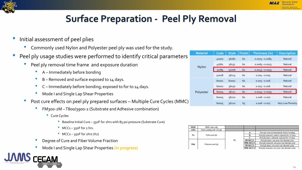
Surface Preparation - Peel Ply Removal
14
• Initial assessment of peel plies
• Commonly used Nylon and Polyester peel ply was used for the study.
• Peel ply usage studies were performed to identify critical parameters
• Peel ply removal time frame and exposure duration
• A – Immediately before bonding
• B – Removed and surface exposed to 14 days.
• C – Immediately before bonding; exposed to for to 14 days.
• Mode I and Single Lap Shear Properties
• Post cure effects on peel ply prepared surfaces – Multiple Cure Cycles (MMC)
• FM300-2M – T800/3900-2 (Substrate and Adhesive combination)
• Cure Cycles
• Baseline Initial Cure – 350F for 2hrs with 85 psi pressure (Substrate Cure)
• MCC1 – 350F for 2 hrs.
• MCC2 – 350F for 2hrs (X2)
• Degree of Cure and Fiber Volume Fraction
• Mode I and Single Lap Shear Properties (in progress)
Material Code Style Finish Thickness [in] Description
Nylon
40000 56180 60 0.0075 – 0.0085 Natural
41661 56137 60 0.0065 – 0.0075 Natural
51789 52006 60 0.0045 – 0.0055 Natural
52008 56115 60 0.004 – 0.005 Natural
Polyester
60001 60001 60 0.005 – 0.006 Natural
60002 56030 60 0.005 – 0.006 Natural
60004 56111 60 0.0045 – 0.0055 Natural
60005 56210 60 0.006 – 0.007 Natural
60005 56210 65 0.006 – 0.007 Very Low Porosity
Peel Ply Thickness Adhesive Test Method
MEK MEK wipe only
120G Hand sanding with 120 grit
A Peel ply removal immediately before bonding
B Peel ply removed, surface exposed for 14 days
C Peel ply intact, substrate exposed for 14 days
PP-MCC1 Peel ply intact, one post cure thermal cycle
PPR-MCC1 Peel ply removed, one post cure thermal cycle
PP-MCC2 Peel ply intact, two post cure thermal cycles
PPR-MCC2 Peel ply removed, two post cure thermal cycles
MEK MEK wipe
120G Hand sanding with 120 grit
PAA PAA + BR 127 primer
AC130.2 AC130-2 + BR 6747-1 primer
Al Aluminum 2024
Ny
EA9394
FM300-2M
D1002
D3167
EA9394
FM300-2M
D3165
D5528
Nylon peel ply
Poly Polyester peel ply
T1
T800 T800H/3900-2 unitape
Substrate Surface Preparation Peel Ply Surface Prep

100
% A
dh
100
% A
dh
100
% A
dh
54%
LF
T, 4
6%
Co
h
74%
LF
T, 2
6%
Co
h
43%
LF
T, 5
7% C
oh
0
10
20
30
40
50
60
70
80
90
0
1000
2000
3000
4000
5000
6000
7000
Ny-
T1-
A
Ny-
T1-
B
Ny-
T1-
C
Po
ly-T
1-A
Po
ly-T
1-B
Po
ly-T
1-C
Ave
rag
e W
ate
r Co
nta
ct An
gle
[de
gre
es]
Ap
pa
ren
t S
he
ar
Str
en
gth
[p
si]
Evaluation of Peel Ply Removal and Exposure D3165 - Single Lap Shear – FM300-2M
A – Immediately before bondingB – Removed and surface exposed to 14 days.C – Immediately before bonding; exposed to for to 14 days.
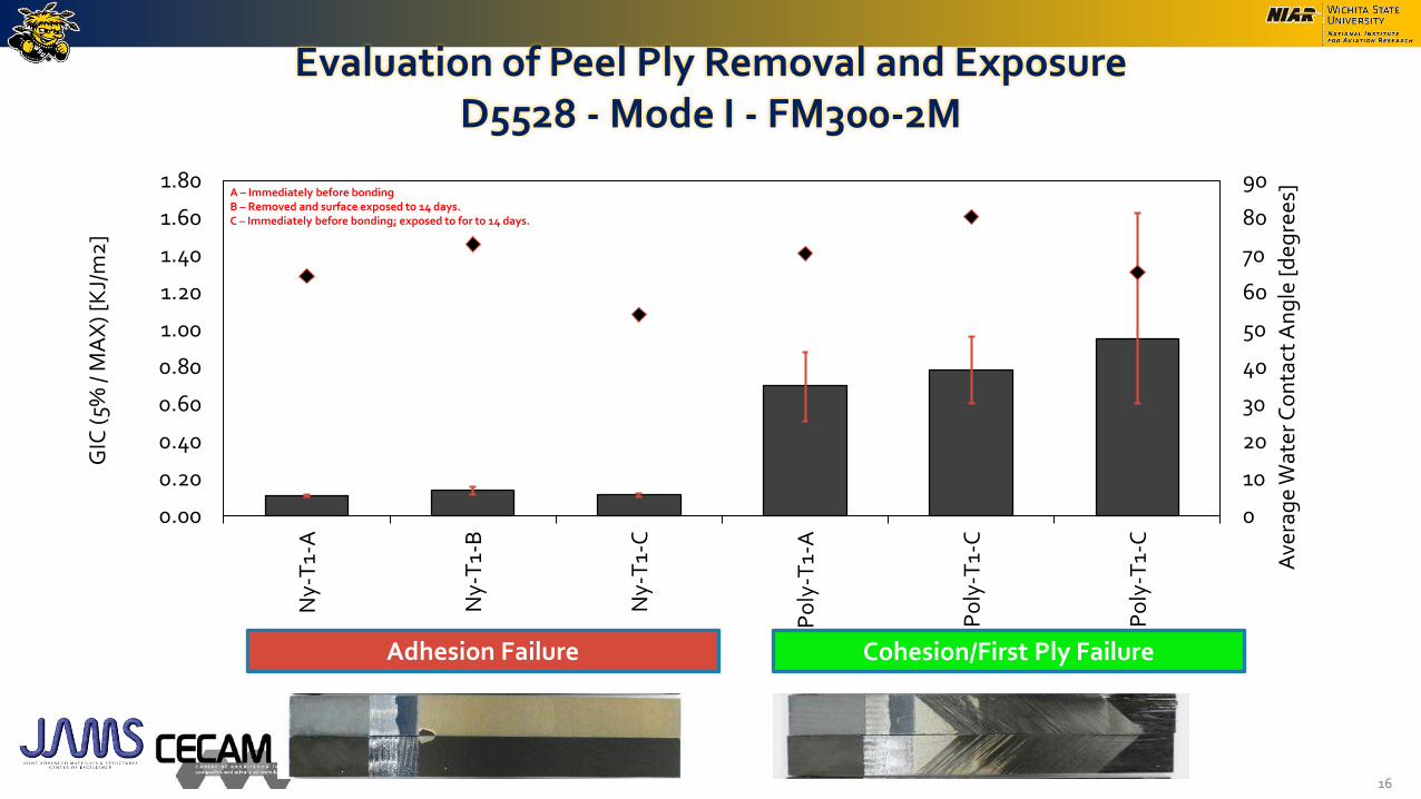
Evaluation of Peel Ply Removal and Exposure D5528 - Mode I - FM300-2M
16
0
10
20
30
40
50
60
70
80
90
0.00
0.20
0.40
0.60
0.80
1.00
1.20
1.40
1.60
1.80
Ny-
T1-
A
Ny-
T1-
B
Ny-
T1-
C
Po
ly-T
1-A
Po
ly-T
1-C
Po
ly-T
1-C
Ave
rag
e W
ater
Co
nta
ct A
ng
le [
deg
rees
]
GIC
(5%
/ M
AX
) [K
J/m
2]
Adhesion Failure Cohesion/First Ply Failure
A – Immediately before bondingB – Removed and surface exposed to 14 days.C – Immediately before bonding; exposed to for to 14 days.

100
% A
dh
3% L
FT
, 97%
Ad
h
100
% A
dh
40
% L
FT
, 60
% A
dh
46
% L
FT
, 54
% A
dh
30%
LF
T, 7
0%
Ad
h
0
10
20
30
40
50
60
70
80
90
0
1000
2000
3000
4000
5000
6000
Ny-
T1-
A
Ny-
T1-
B
Ny-
T1-
C
Po
ly-T
1-A
Po
ly-T
1-B
Po
ly-T
1-C
Ave
rag
e W
ate
r C
on
tact
An
gle
[d
eg
ree
s]
Ap
pa
ren
t S
he
ar
Str
en
gth
[p
si]
Evaluation of Peel Ply Removal and Exposure D3165 - Single Lap Shear – EA 9394
A – Immediately before bondingB – Removed and surface exposed to 14 days.C – Immediately before bonding; exposed to for to 14 days.

0
10
20
30
40
50
60
70
80
90
0.00
0.10
0.20
0.30
0.40
0.50
0.60
0.70
Ny-
T1-
A
Ny-
T1-
B
Ny-
T1-
C
Po
ly-T
1-A
Po
ly-T
1-B
Po
ly-T
1-C
Ave
rag
e W
ater
Co
nta
ct A
ng
le [d
eg
rees
]
GIC
(5%
/ M
AX
) [K
J/m
2]
Evaluation of Peel Ply Removal and Exposure D5528 - Mode I – EA9394
18
Adhesion Failure Cohesion Failure
A – Immediately before bondingB – Removed and surface exposed to 14 days.C – Immediately before bonding; exposed to for to 14 days.

100
% A
dh
100
% A
dh
100
% A
dh
100
% A
dh
21%
LF
T, 7
9%
Ad
h
10%
LFT
, 90
% A
dh
25%
LF
T, 7
5% A
dh
8%
LFT
, 92
% A
dh
0
20
40
60
80
100
120
0
1000
2000
3000
4000
5000
6000
Ny-
T1-
PP
-M
CC
1
Ny-
T1-
PP
-M
CC
2
Ny-
T1-
PP
R-
MC
C1
Ny-
T1-
PP
R-
MC
C2
Po
ly-T
1-P
P-
MC
C1
Po
ly-T
1-P
P-
MC
C2
Po
ly-T
1-P
PR
-M
CC
1
Po
ly-T
1-P
PR
-M
CC
2
Ave
rag
e W
ate
r C
on
tact
An
gle
[d
eg
ree
s]
Ap
pa
ren
t S
he
ar
Str
en
gth
[p
si]
Evaluation of Peel Ply Removal – Multiple Cure Cycles FM300-2M - D3165 Single Lap Shear
19
Substrate - T800/3900-2 Adhesive – FM300-2M
Bond Cure Cycle – 90 mins 250F 40 psiSurface Preparation – Peel Ply
Adhesion Failure Low Cohesion/First Ply – High Adhesion

0
20
40
60
80
100
120
0.00
0.05
0.10
0.15
0.20
0.25
0.30
0.35
Ny-
T1-
PP
-M
CC
1
Ny-
T1-
PP
-M
CC
2
Ny-
T1-
PP
R-M
CC
1
Ny-
T1-
PP
R-M
CC
2
Po
ly-T
1-P
P-M
CC
1
Po
ly-T
1-P
P-M
CC
2
Po
ly-T
1-P
PR
-MC
C1
Po
ly-T
1-P
PR
-MC
C2
Ave
rag
e W
ater
Co
nta
ct A
ng
le
[deg
rees
]
GIC
(5%
/ M
AX
) [K
J/m
2]
Evaluation of Peel Ply Removal – Multiple Cure Cycles FM300-2M – D5528 Mode I
20
Substrate - T800/3900-2 Adhesive – FM300-2M
Bond Cure Cycle – 90 mins 250F 40 psiSurface Preparation – Peel Ply
Adhesion Failure Low Cohesion/First Ply – High Adhesion
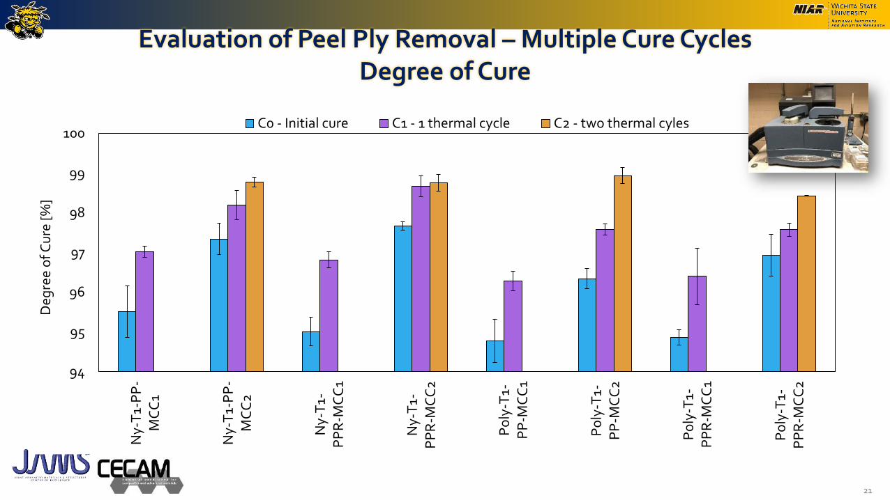
Evaluation of Peel Ply Removal – Multiple Cure Cycles Degree of Cure
21
94
95
96
97
98
99
100N
y-T
1-P
P-
MC
C1
Ny-
T1-
PP
-M
CC
2
Ny-
T1-
PP
R-M
CC
1
Ny-
T1-
PP
R-M
CC
2
Po
ly-T
1-P
P-M
CC
1
Po
ly-T
1-P
P-M
CC
2
Po
ly-T
1-P
PR
-MC
C1
Po
ly-T
1-P
PR
-MC
C2
Deg
ree
of C
ure
[%
]
C0 - Initial cure C1 - 1 thermal cycle C2 - two thermal cyles

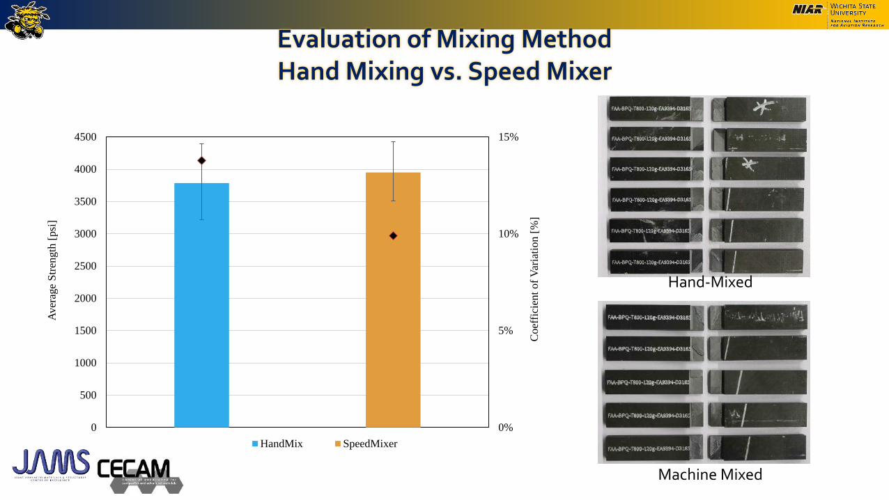
Evaluation of Mixing MethodHand Mixing vs. Speed Mixer
• Hand mixing
• Materials weighed into cup and mixed for 5 minutes. Mixture is then transferred to second cup and mix for an additional 5-10 minutes or until the consistency of the adhesive has changed to become smoother and easier to mix.
• Speed Mixer
• Materials weighed into FlackTek compatible cup and placed inside machine with holder. An appropriate recipe (depending on weight) is chosen and the machine is run.
Zone
A B C
RPM 1000 1600 2000
Time (secs) 60 40 90
Hand mixing Speed Mixer Flacktek DAC
600.1FVZ
Recipe for 125g of adhesive
Evaluation of Mixing MethodHand Mixing vs. Speed Mixer
0%
5%
10%
15%
0
500
1000
1500
2000
2500
3000
3500
4000
4500
Coef
fici
ent
of
Var
iati
on [
%]
Aver
age
Str
ength
[psi
]
HandMix SpeedMixer
Hand-Mixed
Machine Mixed
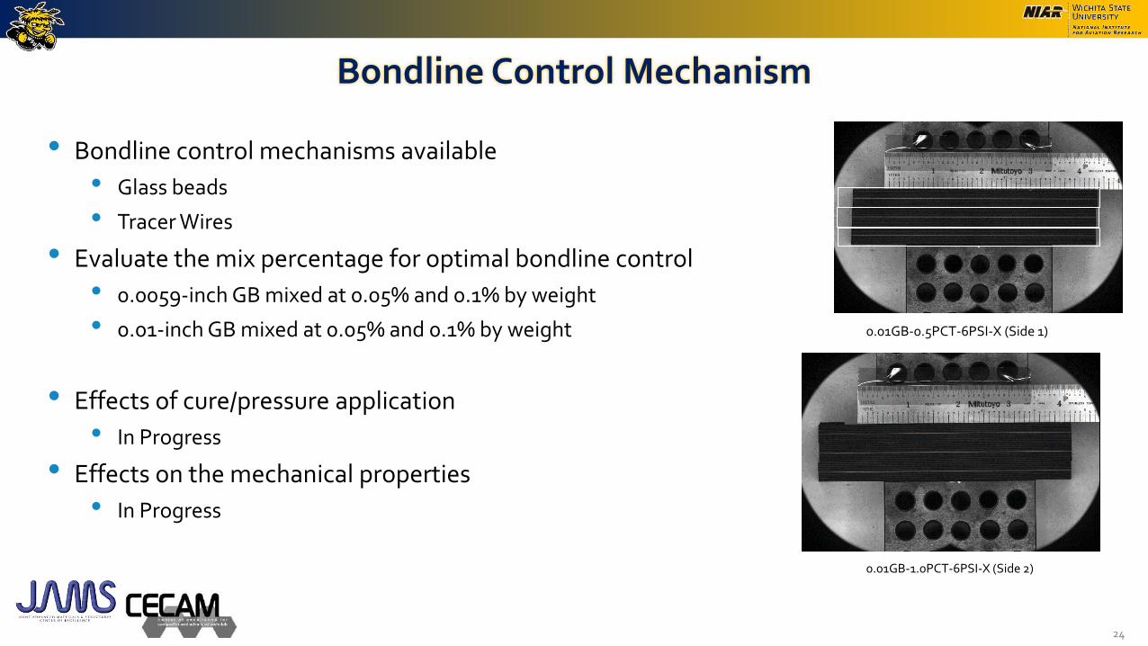
Bondline Control Mechanism
• Bondline control mechanisms available
• Glass beads
• Tracer Wires
• Evaluate the mix percentage for optimal bondline control
• 0.0059-inch GB mixed at 0.05% and 0.1% by weight
• 0.01-inch GB mixed at 0.05% and 0.1% by weight
• Effects of cure/pressure application
• In Progress
• Effects on the mechanical properties
• In Progress
24
0.01GB-0.5PCT-6PSI-X (Side 1)
0.01GB-1.0PCT-6PSI-X (Side 2)

Bondline Control Mechanism
25
0%
5%
10%
15%
20%
25%
30%
0.000
0.002
0.004
0.006
0.008
0.010
0.012
0.014
0.016
0.018
0.020
0.0
05
9in
-0.5
%-F
V
0.0
05
9in
-1.0
%-F
V
0.0
1in
-0.5
%-F
V
0.0
1in
-1.0
%-F
V
0.0
05
9in
-0.5
%-6
psi
0.0
05
9in
-1.0
%-6
psi
0.0
1in
-0.5
%-6
psi
0.0
1in
-1.0
%-6
psi
Co
effi
cien
t o
f V
aria
tio
n [
%]
Av
erag
e B
on
dli
ne
Th
ick
nes
s [i
n]
Summary and Conclusion
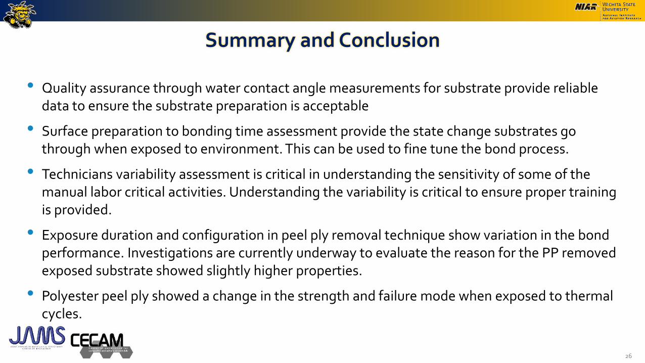
• Quality assurance through water contact angle measurements for substrate provide reliable data to ensure the substrate preparation is acceptable
• Surface preparation to bonding time assessment provide the state change substrates go through when exposed to environment. This can be used to fine tune the bond process.
• Technicians variability assessment is critical in understanding the sensitivity of some of the manual labor critical activities. Understanding the variability is critical to ensure proper training is provided.
• Exposure duration and configuration in peel ply removal technique show variation in the bond performance. Investigations are currently underway to evaluate the reason for the PP removed exposed substrate showed slightly higher properties.
• Polyester peel ply showed a change in the strength and failure mode when exposed to thermal cycles.
26

Looking Forward/Future Work
• Future Works
• Generate bond process protocols for
• Selecting compatible substrate and adhesive combinations for a robust bond structure
• Provide guidance on protocol development for cure process related activities
• Look into other surface preparation methods and look into critical parameters
• Benefit to Aviation
• Generate bond process protocols
• Provide guidance on the critical parameters in the bond process and how to mechanically test them to generate protocols to ensure the integrity of the final bonded product
27

Summary
28
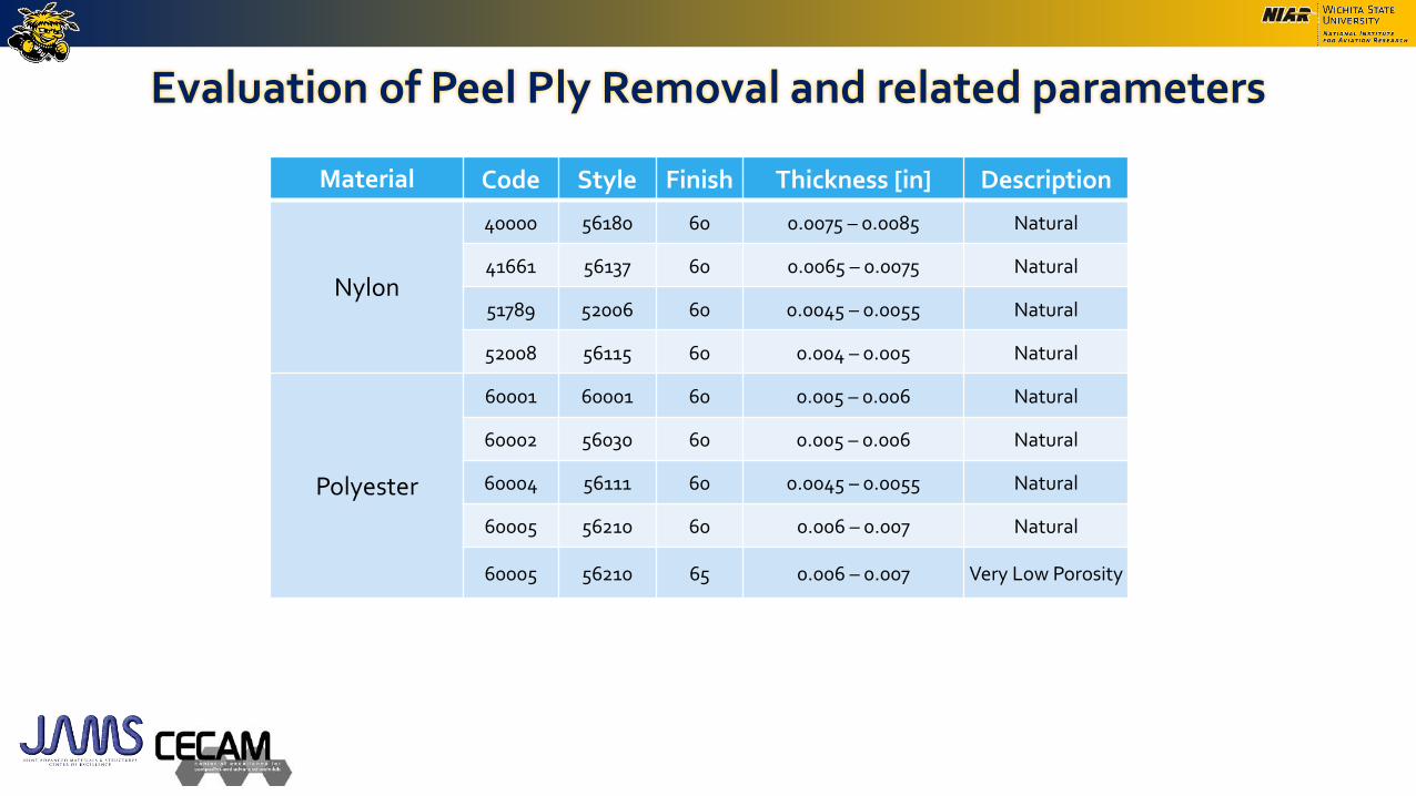
Evaluation of Peel Ply Removal and related parameters
Material Code Style Finish Thickness [in] Description
Nylon
40000 56180 60 0.0075 – 0.0085 Natural
41661 56137 60 0.0065 – 0.0075 Natural
51789 52006 60 0.0045 – 0.0055 Natural
52008 56115 60 0.004 – 0.005 Natural
Polyester
60001 60001 60 0.005 – 0.006 Natural
60002 56030 60 0.005 – 0.006 Natural
60004 56111 60 0.0045 – 0.0055 Natural
60005 56210 60 0.006 – 0.007 Natural
60005 56210 65 0.006 – 0.007 Very Low Porosity
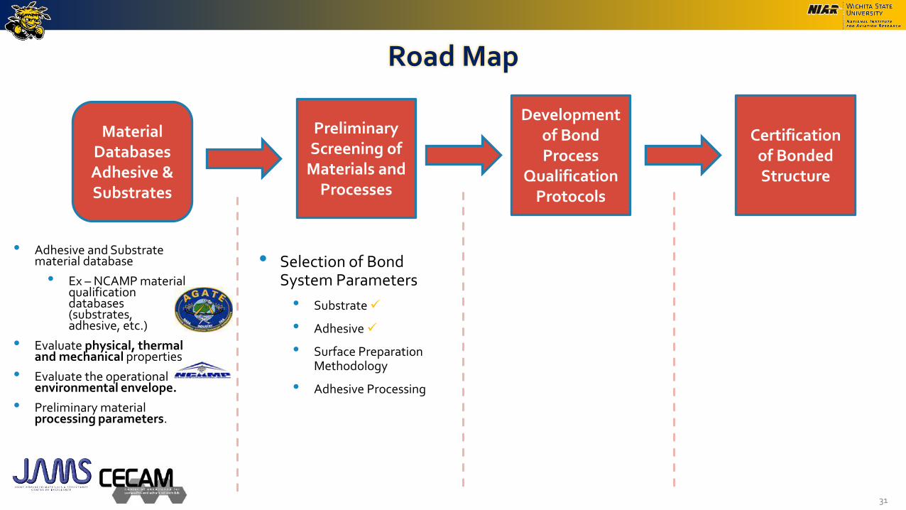
Road Map
31
Preliminary Screening of
Materials and Processes
Development of Bond Process
Qualification Protocols
Certification of Bonded Structure
Material DatabasesAdhesive & Substrates
• Adhesive and Substrate material database
• Ex – NCAMP material qualification databases (substrates, adhesive, etc.)
• Evaluate physical, thermal and mechanical properties
• Evaluate the operational environmental envelope.
• Preliminary material processing parameters.
• Selection of Bond System Parameters
• Substrate
• Adhesive
• Surface Preparation Methodology
• Adhesive Processing
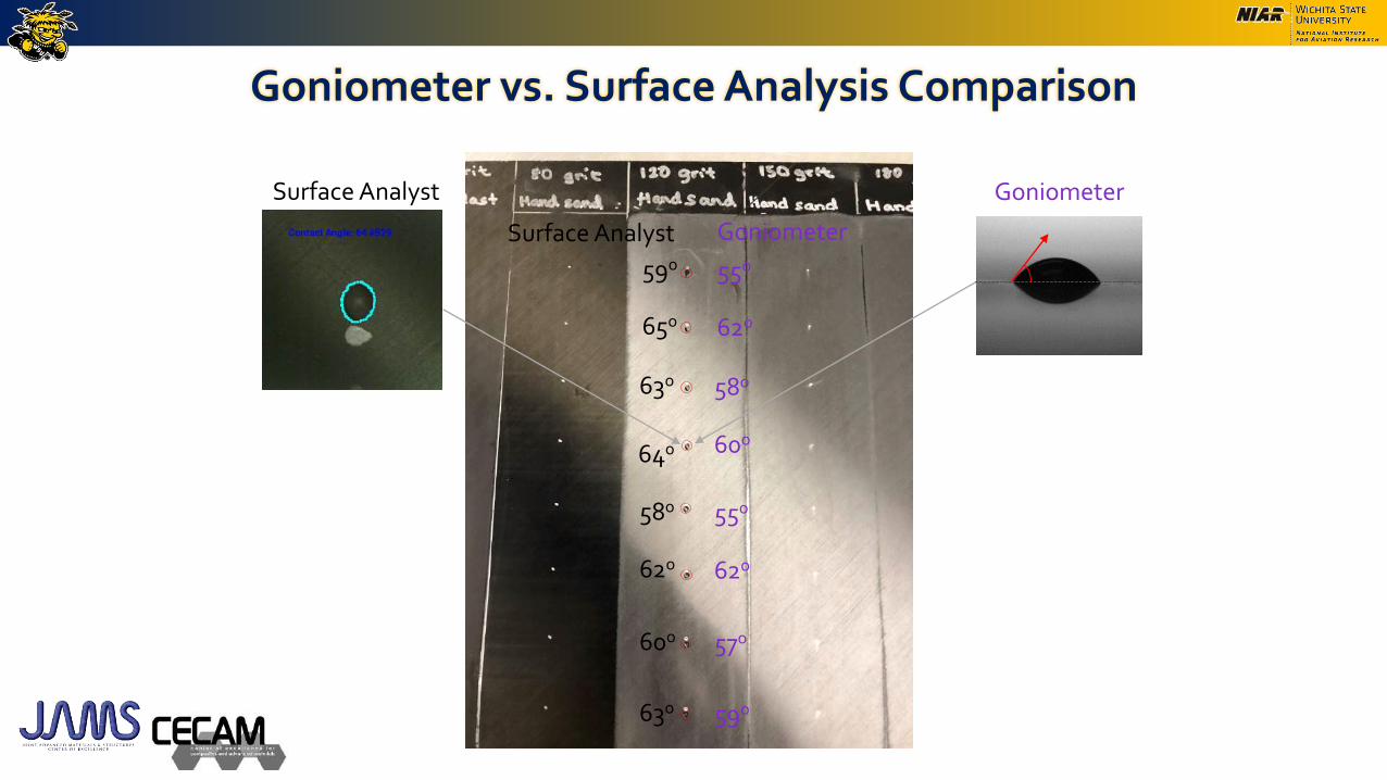
Goniometer vs. Surface Analysis Comparison
59o
65o
63o
64o
58o
62o
60o
63o
55o
62o
58o
60o
55o
62o
57o
59o
Surface Analyst Goniometer
Surface Analyst Goniometer

Goniometer vs. Surface Analysis Comparison
• Average difference of 2 degrees between the SA and goniometer measurements, with a maximum difference of 4 degrees.
54
55
56
57
58
59
60
61
62
63
64
65
66
Point 1 Point 2 Point 3 Point 4 Point 5 Point 6 Point 7 Point 8 Point 9 Point 10 Point 11 Point 12 Point 13 Point 14 Point 15 Point 16
An
gle
[d
egre
es]
Surface Analyst Goniometer
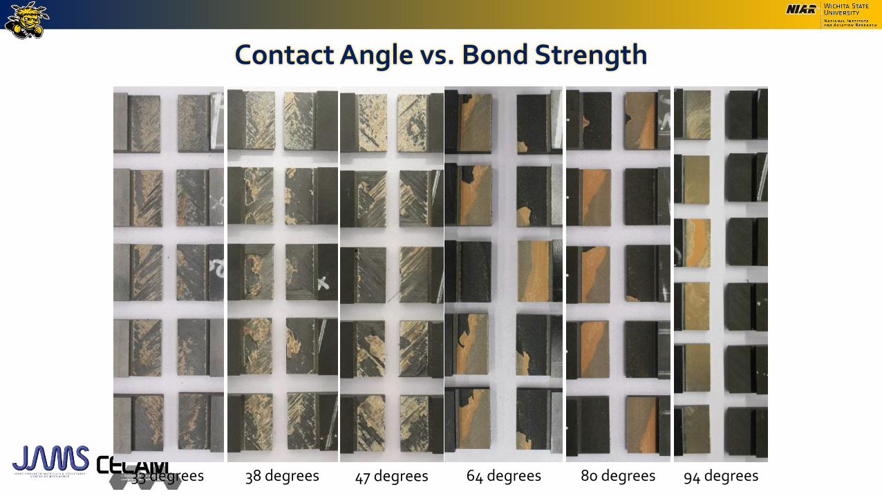
Contact Angle vs. Bond Strength
33 degrees 38 degrees 47 degrees 64 degrees 80 degrees 94 degrees

• Apparent average shear strength for composite D3165 substrates bonded with FM300-2M
Peel Ply study – Single Lap Shear
0%
5%
10%
15%
20%
25%
30%
0
1000
2000
3000
4000
5000
6000
7000
ME
K
120G
Ny-T
1-A
Ny-T
1-B
Ny-T
1-C
Ny-T
1-P
P-
MC
C1
Ny
-T1-P
PR
-
MC
C1
Poly
-T1-A
Poly
-T1-B
Poly
-T1-C
Poly
-T1-P
P-
MC
C1
Poly
-T1-
PP
R-M
CC
1
Coef
fici
ent
of
Vari
ati
on
[%
]
Ap
pare
nt
Sh
ear
Str
ength
[p
si]
ASTM D3165 T800H/3900-2 – FM300-2M
Peel Ply Thickness Adhesive Test Method
MEK MEK wipe only
120G Hand sanding with 120 grit
A Peel ply removal immediately before bonding
B Peel ply removed, surface exposed for 14 days
C Peel ply intact, substrate exposed for 14 days
PP-MCC1 Peel ply intact, one post cure thermal cycle
PPR-MCC1 Peel ply removed, one post cure thermal cycle
PP-MCC2 Peel ply intact, two post cure thermal cycles
PPR-MCC2 Peel ply removed, two post cure thermal cycles
MEK MEK wipe
120G Hand sanding with 120 grit
PAA PAA + BR 127 primer
AC130.2 AC130-2 + BR 6747-1 primer
Al Aluminum 2024
Ny
EA9394
FM300-2M
D1002
D3167
EA9394
FM300-2M
D3165
D5528
Nylon peel ply
Poly Polyester peel ply
T1
T800 T800H/3900-2 unitape
Substrate Surface Preparation Peel Ply Surface Prep

D3165 Failure Modes - FM300-2M
MEK Ny-T1-A Poly-T1-A120G
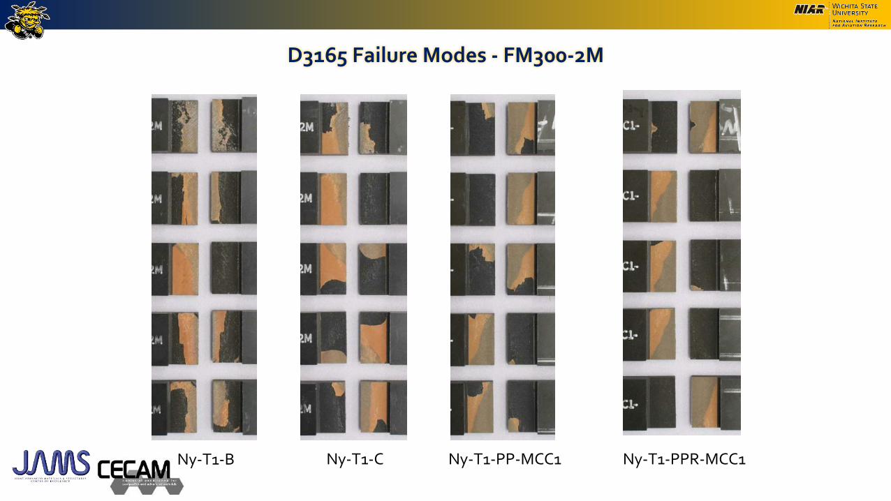
D3165 Failure Modes - FM300-2M
Ny-T1-B Ny-T1-C Ny-T1-PP-MCC1 Ny-T1-PPR-MCC1
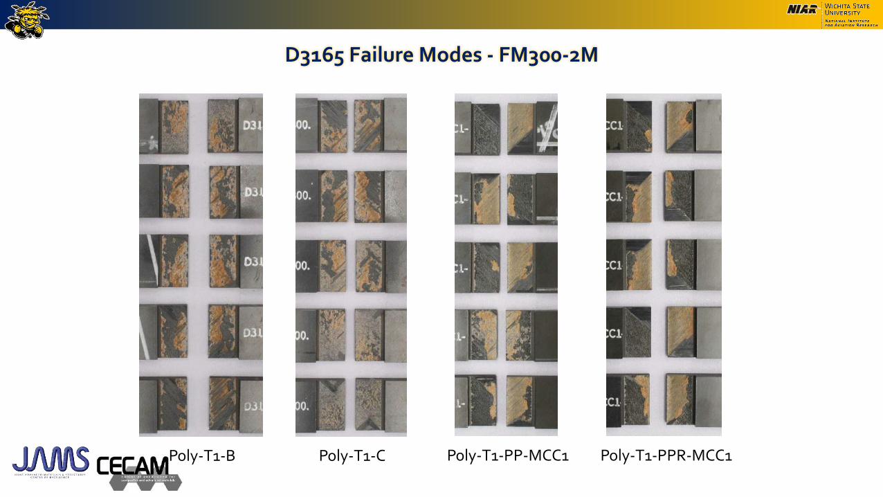
D3165 Failure Modes - FM300-2M
Poly-T1-B Poly-T1-C Poly-T1-PP-MCC1 Poly-T1-PPR-MCC1
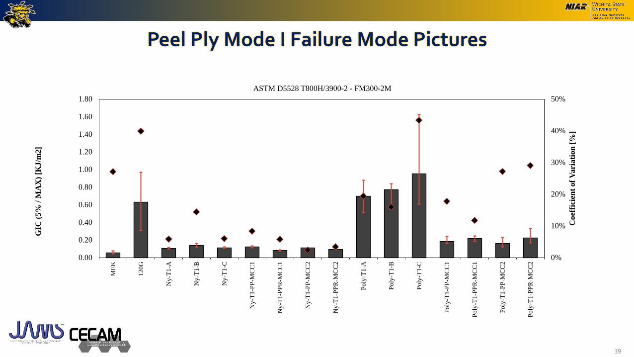
Peel Ply Mode I Failure Mode Pictures
39
0%
10%
20%
30%
40%
50%
0.00
0.20
0.40
0.60
0.80
1.00
1.20
1.40
1.60
1.80
ME
K
120
G
Ny
-T1-A
Ny
-T1-B
Ny
-T1-C
Ny
-T1-P
P-M
CC
1
Ny
-T1-P
PR
-MC
C1
Ny
-T1-P
P-M
CC
2
Ny
-T1-P
PR
-MC
C2
Po
ly-T
1-A
Po
ly-T
1-B
Po
ly-T
1-C
Po
ly-T
1-P
P-M
CC
1
Po
ly-T
1-P
PR
-MC
C1
Po
ly-T
1-P
P-M
CC
2
Po
ly-T
1-P
PR
-MC
C2
Coef
fici
ent
of
Vari
ati
on
[%
]
GIC
(5%
/ M
AX
) [K
J/m
2]
ASTM D5528 T800H/3900-2 - FM300-2M

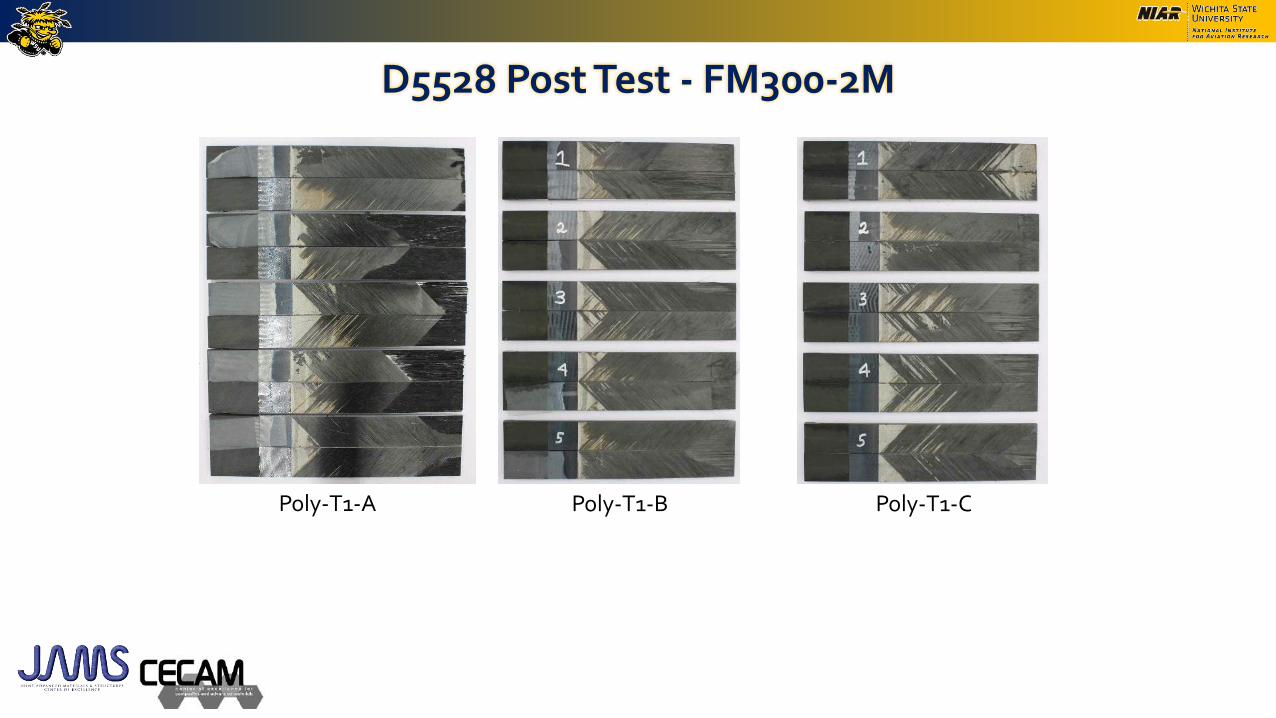
D5528 Post Test - FM300-2M
MEK 120G
D5528 Post Test - FM300-2M
Poly-T1-B Poly-T1-CPoly-T1-A

D5528 Post Test - FM300-2M
Poly-T1-PP-MCC1 Poly-T1-PPR-MCC1
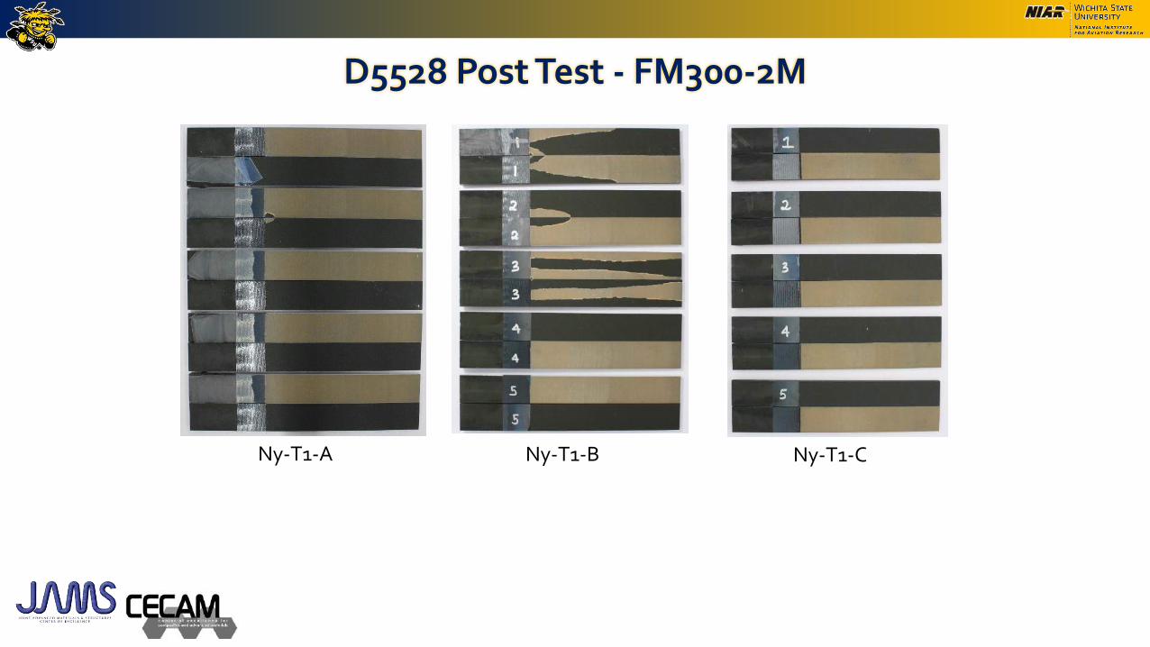
D5528 Post Test - FM300-2M
Ny-T1-A Ny-T1-B Ny-T1-C
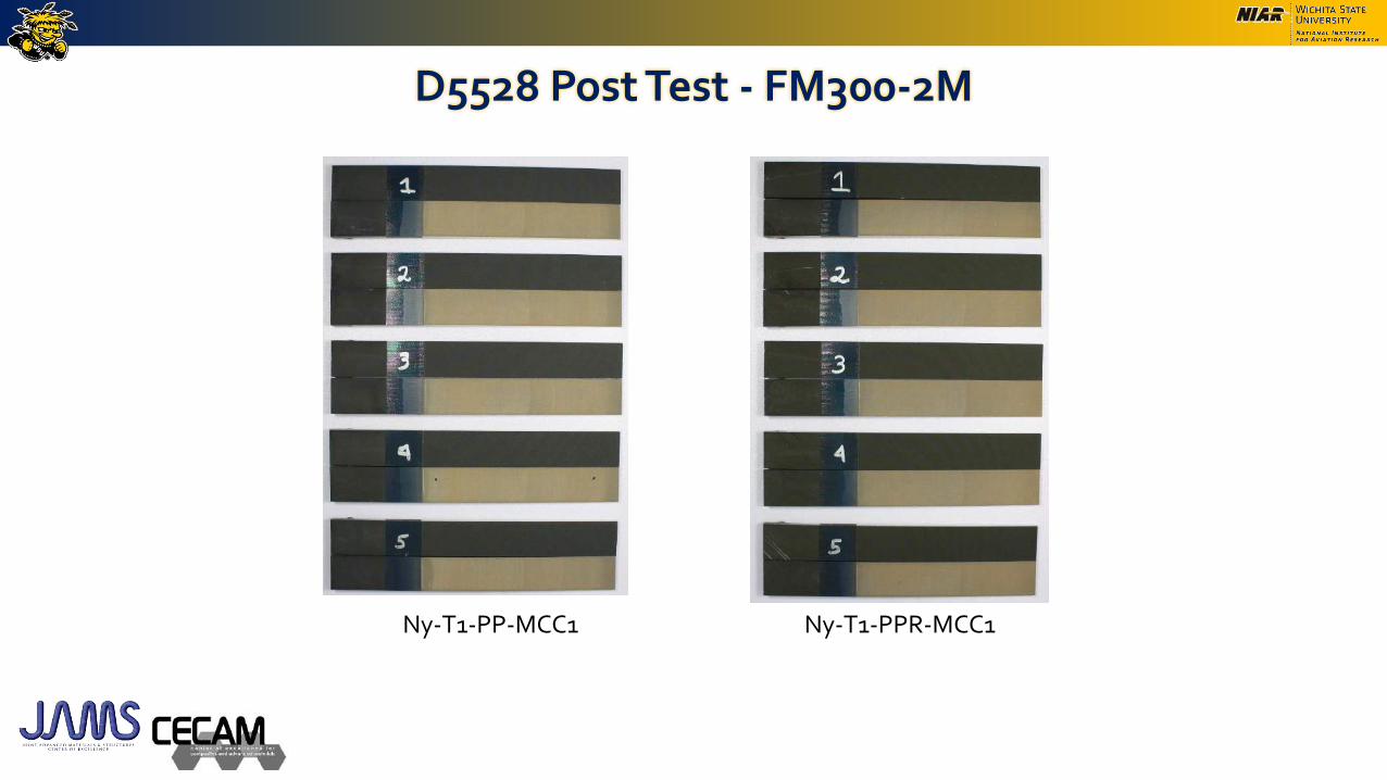
D5528 Post Test - FM300-2M
Ny-T1-PP-MCC1 Ny-T1-PPR-MCC1

• All measurements were taken in the 0o direction.
Peel Ply – Surface Roughness
ME
K
Ny-T
1-A
Ny-T
1-B
Ny-T
1-C
Ny-T
1-P
P-M
CC
1
Ny-T
1-P
PR
-MC
C1
Poly
-T1
-A
Poly
-T1
-B
Poly
-T1
-C
Poly
-T1
-PP
-MC
C1
Poly
-T1
-PP
R-M
CC
1
0%
5%
10%
15%
20%
0
50
100
150
200
250
300
350
400
450
500
Co
effi
cien
t o
f V
ari
ati
on
[%
]
Av
era
ge
Ra
[μ
in]
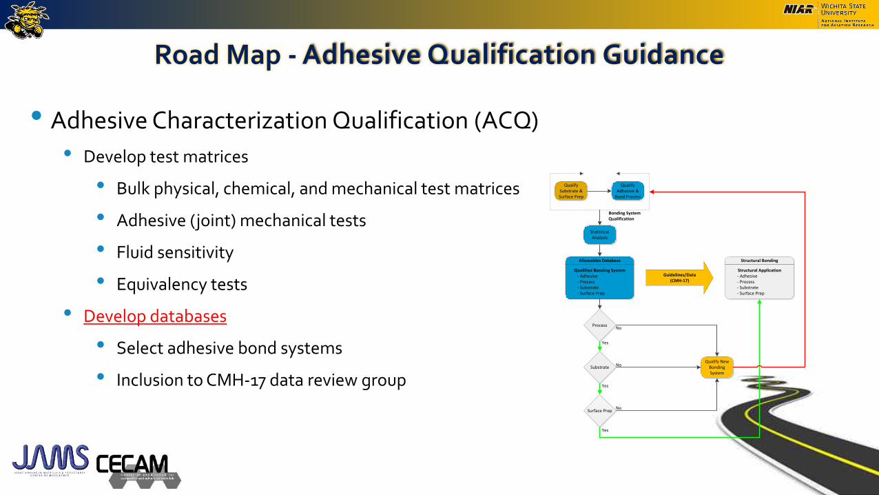
Road Map - Adhesive Qualification Guidance
• Adhesive Characterization Qualification (ACQ)
• Develop test matrices
• Bulk physical, chemical, and mechanical test matrices
• Adhesive (joint) mechanical tests
• Fluid sensitivity
• Equivalency tests
• Develop databases
• Select adhesive bond systems
• Inclusion to CMH-17 data review group
46
Allowables Database
Qualified Bonding System- Adhesive- Process- Substrate- Surface Prep
Process
Substrate
Surface Prep
Guidelines/Data(CMH-17)
Structural Bonding
Structural Application- Adhesive- Process- Substrate- Surface Prep
Qualify New Bonding System
Yes
No
Yes
No
No
Yes
Bonding System Qualification
Qualify Substrate & Surface Prep
Qualify Adhesive &
Bond Process
Statistical Analysis

Road Map - Adhesive Qualification Guidance
47
Guideline Document(FAA Report)
NCAMP Material Specification (NMS)
NCAMP Process Specification (NPS)
Solvey FM300-2
Loctite EA9394
NMS 300/1FM300-2M 0.06 psf
NMS 394/1EA 9394 AERO
Qualified Product List (QPL)
· NMS 300/1· NMS 394/1· ...
Solvey FM300-2
Loctite EA9394
Material Specifications
Process Specifications
Fabrication of bulk and
mechanical test panels
Adhesive NRP 102Adhesive Process Control Document (PCD) Preparation and Maintenance Guide
Guidelines and Recommended Criteria for the Development of Material/Process Specifications for Adhesive
Development of NCAMP Specifications
NCAMP Test Plan (NTP)
Solvey FM300-2
Loctite EA9394
Test Plans
Conformity
Data Collection Templates (PMC)
Authorized Inspection Representative (AIR)
Authorized Engineering Representative (AER)
Material Property Data Report
Statistical Analysis Report
FAA Special Project Codes (SPC)
Development of NCAMP Test Plans

Development of NCAMP Specifications, Test Plans & Guidelines
48
• Adhesive System 1 – FM300-2M (Film Adhesive)
• NCAMP Material Specification (Base) – NMS300
• NCAMP Material Specification (Slash) – NMS300/1
• NCAMP Process Specifications - NPS 83002
• NCAMP Test Plan - NTP AC-3002Q1
• Adhesive System 2 – EA9394 bare (Paste Adhesive)
• NCAMP Material Specification (Base) – NMS394
• NCAMP Material Specification (Slash) – NMS394/1
• NCAMP Process Specifications - NPS 89394
• NCAMP Test Plan - NTP AC-9394Q1
• Adhesive Process Control Document (PCD) – NRP 105
• NCAMP - Adhesive Data Collection Forms

Current Status
49
C1 C2 C1 C2 C1 C2
CTD 3 3 3 3 3 3
ETD 3 3
ETW 3 3 3 3 3 3
RTD 3 3 3 3 3 3
CTD 3 3
ETD 3 3
ETW 3 3
RTD 3 3
CTD 3 3
ETD 3 3
ETW 3 3
RTD 3 3
CTD 3 3 3 3 3 3
ETD 3 3
ETW 3 3 3 3 3 3
RTD 3 3 3 3 3 3
CTD 3 3
ETD 3 3
ETW 3 3
RTD 3 3
CTD 3 3
ETD 3 3
ETW 3 3
RTD 3 3
CTD 3 3 3 3 3 3
ETD 3 3
ETW 3 3 3 3 3 3
RTD 3 3 3 3 3 3
CTD 3 3 3 3 3 3
ETD 3 3
ETW 3 3 3 3 3 3
RTD 3 3 3 3 3 3
ET 30
RT 30
Batch A Batch B Batch C
Thin Metal
Adherend
Lap Shear
D1002
Thick Metal
Adherend
Lap Shear
D5656 (T1)
Floating
Roller PeelD3167
Mode I
Fracture
Toughness
D3433
Mode II
Fracture
Toughness
D7905
Thick Metal
Adherend
Lap Shear
D5656 (T2)
Composite
Adherend
Lap Shear
D3165
D1002FSFluid
Sensitivity
Flatwise
TensileD897
EA9394
Property Test MethodTest
Environment
C1 C2 C1 C2 C1 C2
CTD 3 3 3 3 3 3
ETD 3 3
ETW 3 3 3 3 3 3
RTD 3 3 3 3 3 3
CTD 3 3
ETD 3 3
ETW 3 3
RTD 3 3
CTD 3 3 3 3 3 3
ETD 3 3
ETW 3 3 3 3 3 3
RTD 3 3 3 3 3 3
CTD 3 3
ETD 3 3
ETW 3 3
RTD 3 3
CTD 3 3
ETD 3 3
ETW 3 3
RTD 3 3
CTD 3 3 3 3 3 3
ETD 3 3
ETW 3 3 3 3 3 3
RTD 3 3 3 3 3 3
CTD 3 3
ETD 3 3
ETW 3 3
RTD 3 3 3 3 3 3
ET 30
RT 30
D3433
Thin Metal
Adherend
Lap Shear
D1002
Thick Metal
Adherend
Lap Shear
D5656
Flatwise
TensileD897
Mode II
Fracture
Toughness
D7905
Floating
Roller PeelD3167
Composite
Adherend
Lap Shear
D3165
Fluid
Sensitivity
FM300-2M
Property Test MethodTest
Environment
D1002FS
Mode I
Fracture
Toughness
Batch A Batch B Batch C
Waiting on Adhesive Batch
Specimen/Panel Bonding in Progress
Specimen Machining in Progress
Conditioning in Progress
Testing in Progress
Testing Complete
EA 9394 FM300-2M

Look Forward
• Future Activities
• Generate the B-Basis allowable for EA9394 and FM300-2M material systems
• Focus on performing equivalency on adhesive materials.
• Analyze failure modes for different test environments and report them accordingly
• Benefit to the Aviation Community
• Guidance on test matrices for mechanical, physical and chemical characterization of adhesives
• Generate adhesive material databases under NCAMP protocols that can be used for a wide variety of applications be different end users
50
Bond Process Qualification Protocols - Road Map
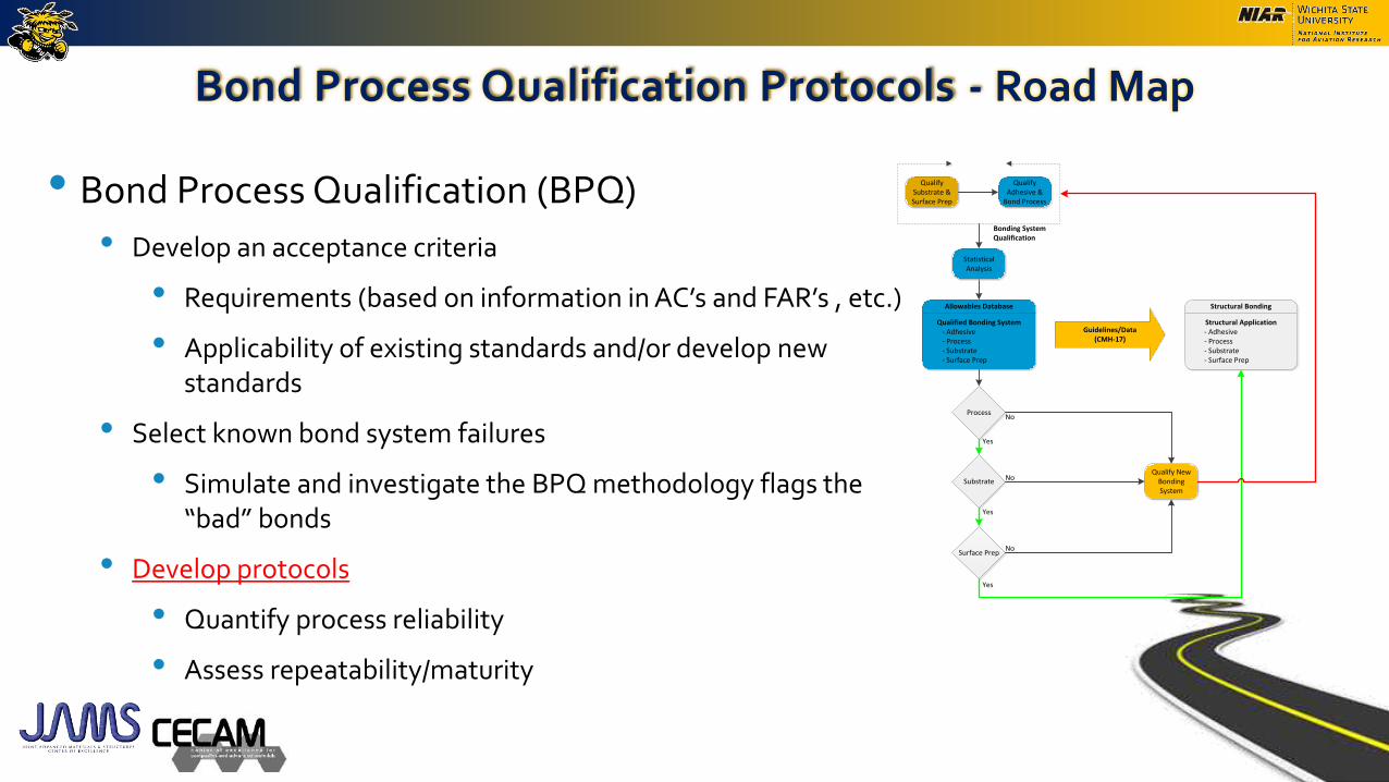
• Bond Process Qualification (BPQ)
• Develop an acceptance criteria
• Requirements (based on information in AC’s and FAR’s , etc.)
• Applicability of existing standards and/or develop new standards
• Select known bond system failures
• Simulate and investigate the BPQ methodology flags the “bad” bonds
• Develop protocols
• Quantify process reliability
• Assess repeatability/maturity
51
Allowables Database
Qualified Bonding System- Adhesive- Process- Substrate- Surface Prep
Process
Substrate
Surface Prep
Guidelines/Data(CMH-17)
Structural Bonding
Structural Application- Adhesive- Process- Substrate- Surface Prep
Qualify New Bonding System
Yes
No
Yes
No
No
Yes
Bonding System Qualification
Qualify Substrate & Surface Prep
Qualify Adhesive &
Bond Process
Statistical Analysis

Bond Process Qualification (Critical Factors)
52
Substrate
Metal Composites
Surface Preparation
Degreasing Abrasion Chemical Treatment
Can be combined
Type
Primer
Bond Process Qualification[Critical Factors]
Surface PreparationMaterial & Process
Variability (Material Qualification)
Pre-Bond Surface Characterization
Adhesive
Material Batch Variability Process Variability History Quality
Paste Film
Mixing(for Paste)
Adhesive Application Bondline Thickness Control Cure Environment Effects of Defects
TgViscosity
Shelf lifeStorage lifeOuttime
TemperatureHumidityField Repair Conditions
Multiple Cure OptionsTooling CTE MismatchTemperature ControlsRamp Rate(s)Pressure
Application MethodOpen Time
(ex., Amine Blush)
Paste Film
Pre-Mixed Glass BeadsGlass Bead Mixing into
Adhesive Mix
Knit Random Mat
Unsupported
Application side(s)ApplicatorPreheat SubstratePreheat AdhesiveAdhesive Fillets
TolerancesVacuum or notMixing Technique
Scrim ClothMicro Beads Mixed into
Adhesive
X-Ray Photoelectron Spectroscopy
Fourier Transform IR Spectroscopy (FTIR)
Sessile Drop Contact Angle (CA)
Grit Blasting Hand Sanding Peel-Ply RemovalPlasma (Ionized Gas)
Treatment
Applicator Mix RatioMixing Technique
• Substrate type• Metal• Composite
• Adhesive types• Film• Paste

Summary of Activities
• Current Activities
• Task 1 – Substrate and adhesive compatibility
• Task 2 – Use of peel ply for composite substrate preparation
• Completed Activities
• Effects of Mix-ratio in two part paste adhesives
• Evaluation of assembly time in paste adhesives
• Amine blush effects
• Fluid Sensitivity of adhesive
• Efficient adhesive screening method testing.
53
54
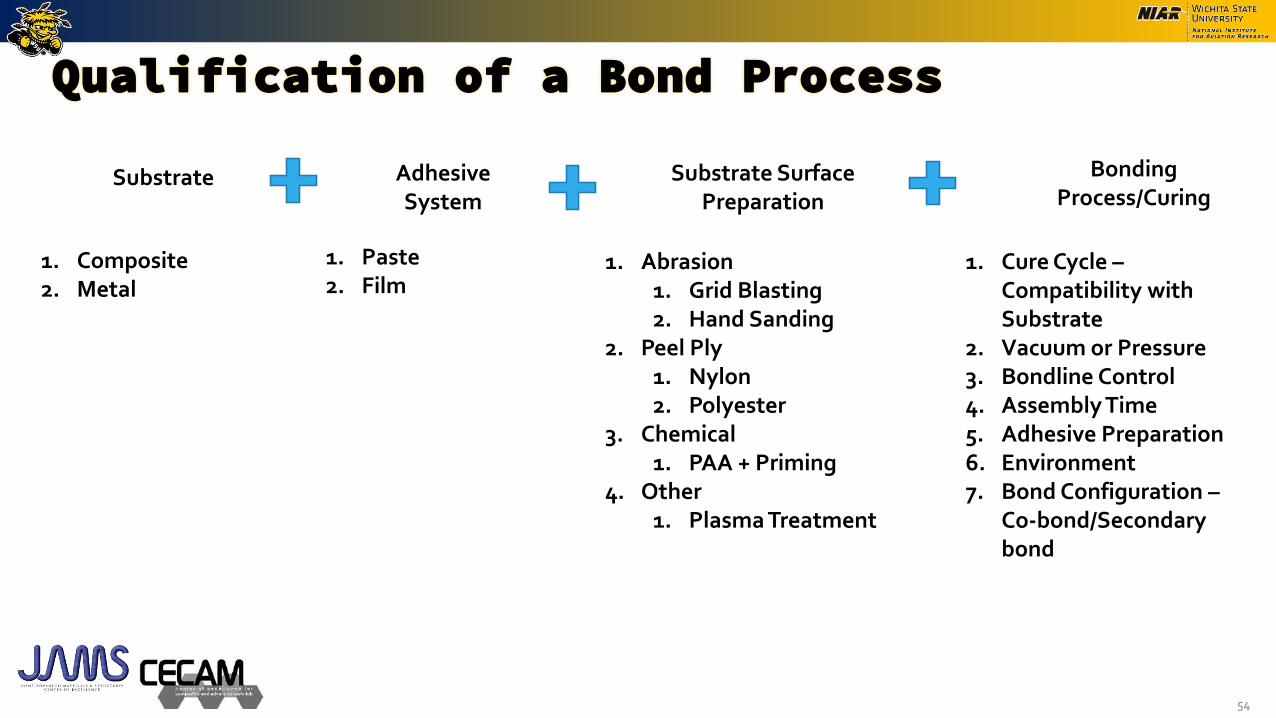
Qualification of a Bond Process
Substrate Adhesive System
Substrate Surface Preparation
Bonding Process/Curing
1. Composite2. Metal
1. Paste 2. Film
1. Abrasion 1. Grid Blasting2. Hand Sanding
2. Peel Ply1. Nylon2. Polyester
3. Chemical1. PAA + Priming
4. Other1. Plasma Treatment
1. Cure Cycle –Compatibility with Substrate
2. Vacuum or Pressure3. Bondline Control4. Assembly Time5. Adhesive Preparation6. Environment7. Bond Configuration –
Co-bond/Secondary bond
55
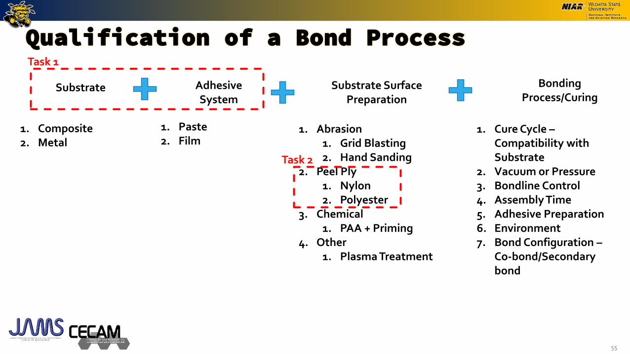
Qualification of a Bond Process
Substrate Adhesive System
Substrate Surface Preparation
Bonding Process/Curing
1. Composite2. Metal
1. Paste 2. Film
1. Abrasion 1. Grid Blasting2. Hand Sanding
2. Peel Ply1. Nylon2. Polyester
3. Chemical1. PAA + Priming
4. Other1. Plasma Treatment
1. Cure Cycle –Compatibility with Substrate
2. Vacuum or Pressure3. Bondline Control4. Assembly Time5. Adhesive Preparation6. Environment7. Bond Configuration –
Co-bond/Secondary bond
Task 1
Task 2

• When using bonded joints for primary or secondary structure applications, there is a wide variety of substrates and adhesive materials that are available for use. Providing Guidance on selecting a compatible substrate and a adhesive combination is important for designers.
• Main factors to consider during adhesive and substrate selection are the mechanical property requirements, physical compatibility of the substrates (hybrid and non-hybrid) and adhesives for bonding, thermal compatibility of the bond system during the bonding process and service life.
• Objective of this task is to provide establish a set of guidelines to use when selecting an adhesive and substrate combination for a given bond process.
Goal – Develop guidelines on how to select compatible substrate and adhesive combinations to obtain a robust bond system
Task 1 –Qualification of a Bond Process – Substrate and Adhesive Compatibility - Background and Goals
57
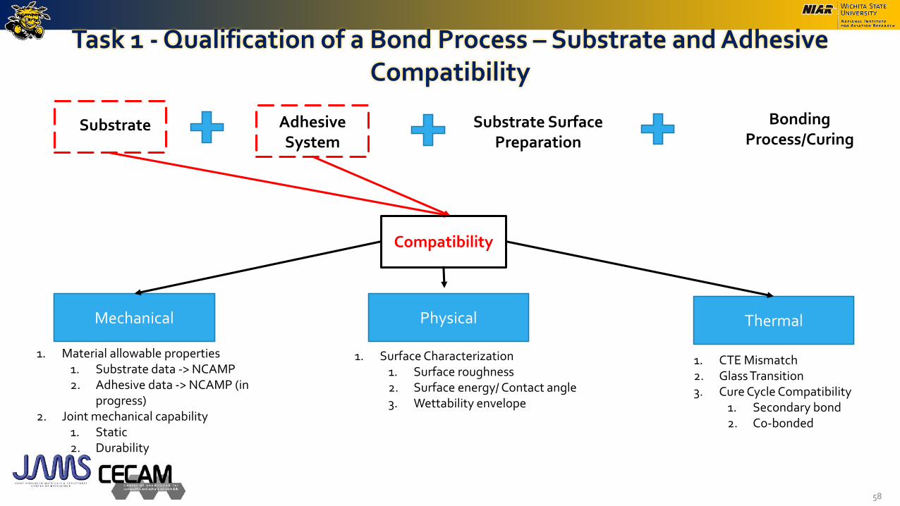
Task 1 - Qualification of a Bond Process – Substrate and Adhesive Compatibility
58
Substrate Adhesive System
Substrate Surface Preparation
Bonding Process/Curing
Compatibility
Physical Thermal
1. Surface Characterization1. Surface roughness2. Surface energy/ Contact angle3. Wettability envelope
1. CTE Mismatch2. Glass Transition3. Cure Cycle Compatibility
1. Secondary bond2. Co-bonded
Mechanical
1. Material allowable properties1. Substrate data -> NCAMP2. Adhesive data -> NCAMP (in
progress)2. Joint mechanical capability
1. Static 2. Durability
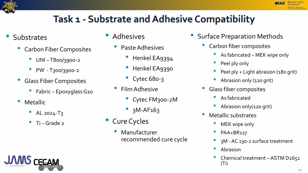
Task 1 - Substrate and Adhesive Compatibility
• Substrates
• Carbon Fiber Composites
• UNI – T800/3900-2
• PW - T300/3900-2
• Glass Fiber Composites
• Fabric – Epoxyglass G10
• Metallic
• AL 2024-T3
• Ti – Grade 2
59
• Adhesives
• Paste Adhesives
• Henkel EA9394
• Henkel EA9390
• Cytec 680-3
• Film Adhesive
• Cytec FM300-2M
• 3M-AF163
• Cure Cycles
• Manufacturer recommended cure cycle
• Surface Preparation Methods
• Carbon fiber composites
• As fabricated – MEK wipe only
• Peel ply only
• Peel ply + Light abrasion (180 grit)
• Abrasion only (120 grit)
• Glass fiber composites
• As fabricated
• Abrasion only(120 grit)
• Metallic substrates
• MEK wipe only
• PAA+BR127
• 3M - AC 130-2 surface treatment
• Abrasion
• Chemical treatment – ASTM D2651 (Ti)

Task 1 - Substrate and Adhesive Compatibility Assessment Physical Compatibility
• Objective
• Generate guidelines to ensure the surface preparation + substrates are physically compatible for bonding.
• Physical Compatibility
• Surface morphology related tests for substrates
• Surface roughness
• Contact angle
• Surface Energy
• Wettability envelope development
• Measure polar and dispersive surface energies for substrate and compare the surface energy of the adhesive.
• Objective:- A simplistic rapid approach to evaluate if the adhesive surface tension falls within the wettability envelope == Good bond
• Perform qualitative tests to assess the bond failures
• Wedge crack
• Rapid adhesion test
• Flatwise tensile
60
A
C
D
0
10
20
30
40
0 10 20 30
Dis
per
sive
/ m
N m
-1
Polar / mN m-1
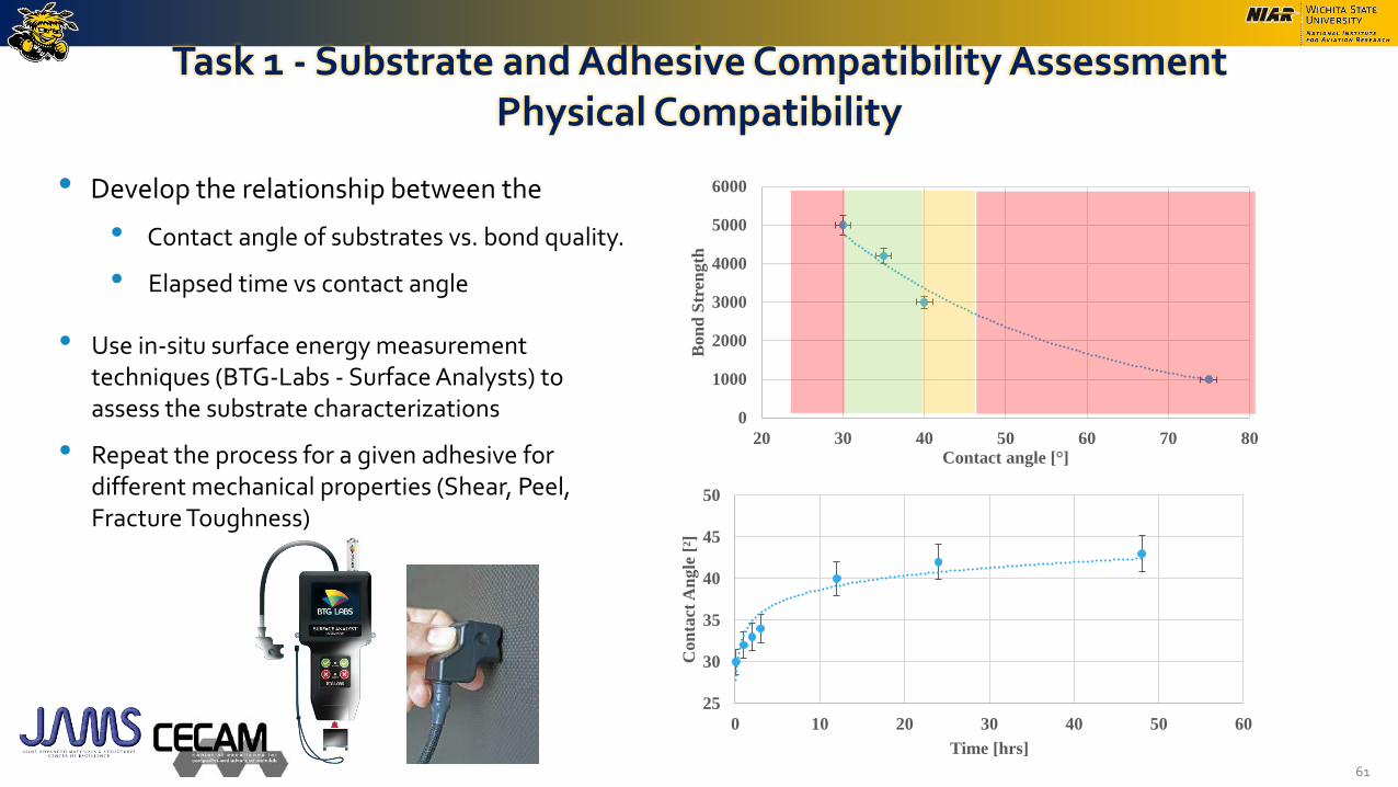
Task 1 - Substrate and Adhesive Compatibility Assessment Physical Compatibility
• Develop the relationship between the
• Contact angle of substrates vs. bond quality.
• Elapsed time vs contact angle
61
• Use in-situ surface energy measurement techniques (BTG-Labs - Surface Analysts) to assess the substrate characterizations
• Repeat the process for a given adhesive for different mechanical properties (Shear, Peel, Fracture Toughness)
0
1000
2000
3000
4000
5000
6000
20 30 40 50 60 70 80
Bon
d S
tren
gth
Contact angle [°]
25
30
35
40
45
50
0 10 20 30 40 50 60
Con
tact
An
gle
[²]
Time [hrs]
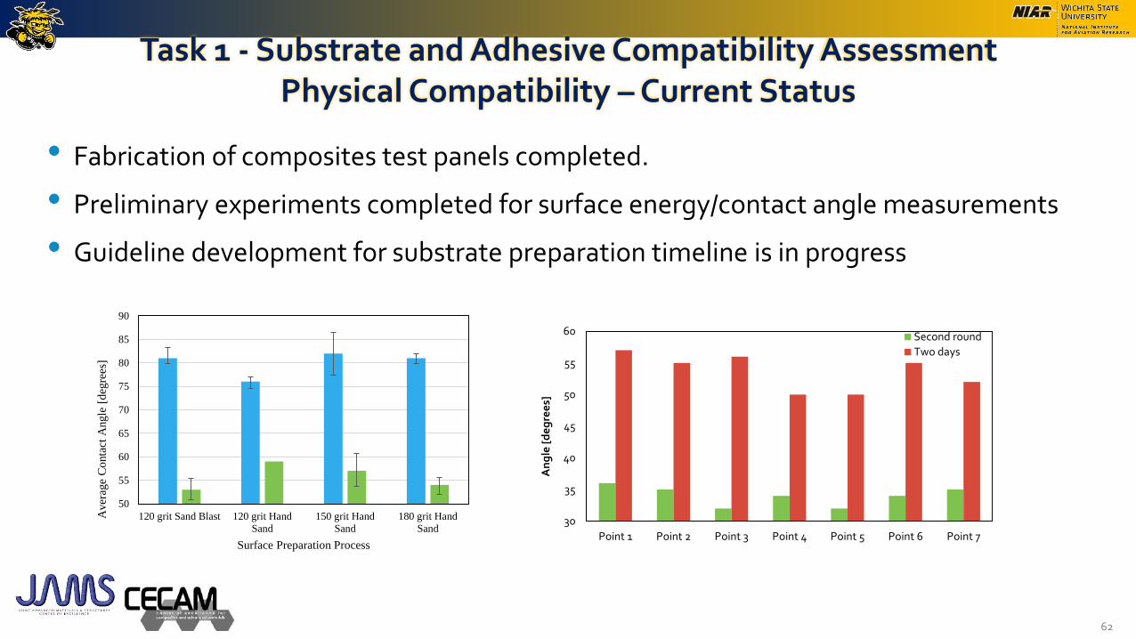
Task 1 - Substrate and Adhesive Compatibility Assessment Physical Compatibility –Current Status
• Fabrication of composites test panels completed.
• Preliminary experiments completed for surface energy/contact angle measurements
• Guideline development for substrate preparation timeline is in progress
62
50
55
60
65
70
75
80
85
90
120 grit Sand Blast 120 grit Hand
Sand
150 grit Hand
Sand
180 grit Hand
Sand
Aver
age
Co
nta
ct A
ngle
[d
egre
es]
Surface Preparation Process
30
35
40
45
50
55
60
Point 1 Point 2 Point 3 Point 4 Point 5 Point 6 Point 7A
ng
le [
de
gre
es]
Second round
Two days
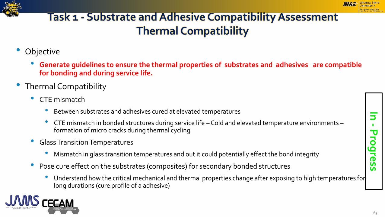
Task 1 - Substrate and Adhesive Compatibility Assessment Thermal Compatibility
• Objective
• Generate guidelines to ensure the thermal properties of substrates and adhesives are compatible for bonding and during service life.
• Thermal Compatibility
• CTE mismatch
• Between substrates and adhesives cured at elevated temperatures
• CTE mismatch in bonded structures during service life – Cold and elevated temperature environments –formation of micro cracks during thermal cycling
• Glass Transition Temperatures
• Mismatch in glass transition temperatures and out it could potentially effect the bond integrity
• Pose cure effect on the substrates (composites) for secondary bonded structures
• Understand how the critical mechanical and thermal properties change after exposing to high temperatures for long durations (cure profile of a adhesive)
63
In -
Pro
gre
ss

Substrate and Adhesive Compatibility Assessment Mechanical Properties
• Mechanical Properties
• Coupon level testing
• Perform coupon level testing to evaluate static and durability capability. (using the actual bond process that will be used for the application)
• Shear
• Peel
• Fracture toughness
• Element/Component level testing
• Fabricate a representative bonded structures
• Perform mechanical testing (static and fatigue)
• Assess the bond quality / Perform NDI
64
Fu
ture
Act
ivit
ies

Task 1 - Substrate and Adhesive CompatibilityAdditional Tasks
• Extend current research with industry partners to further investigate substrate adhesive compatibility.
• Substrate Material – Tencate T350-1/IM7
• Adhesive System – EA 9394
65
#Batch #Spec. #Batch #Spec. #Batch #Spec. #Batch #Spec.
0.015 1 6 1 6 1 6 1 6
0.04 3 18 3 18 3 18 3 18
0.08 1 6 1 6 1 6 1 6
0.125 1 6 1 6 1 6 1 6
Lap Shear and Stress/Strain ASTM D5656 - (Al – thick) 0.015 1 6 3 18 1 6 1 6
T-Peel ASTM D1876 - Composites 0.015 1 6 3 18 1 6 1 6
Floating Roller Peel ASTM D3167 0.015 1 6 3 18 1 6 1 6
Fracture Toughness ASTM D3433 0.015 1 6 3 18 1 6 1 6
Flatwise Tensile ASTM D897 0.015 1 6 3 18 1 6 1 6
Test Type Test MethodBondline
Thickness [in]
ASTM D3165 - Composites
ASTM D1002 - (Al -thin) 1 6 1 6Single Lap Shear 0.015 1 6 3 18
CTD RTD ETD ETW
Single Lap Shear

• Use of peel ply as a surface preparation method reduces the amount of labor involved and simplify the substrate preparation process. It also provides a uniform and repeatable surface for bonding
• Peel ply prepared surface quality vary on many substrate and surface preparation process parameters. Bond surface quality directly effects the bond integrity. Understanding the effects of these parameters is critical. Development of reliable and rapid inspection methods is crucial to ensure the bond process (surface preparation) method is appropriate for a given bond system.
• After an appropriate peel ply surface preparation method is chosen, there are many other parameters associated with handling substrates that could potentially change the quality of the bond surfaces. These parameters and their adverse effect on the bond integrity needs to be evaluated to provide Guidance and Develop Protocols to have a robust bond system.
Goal – Develop guidelines and protocols to handle peel ply prepared surfaces to obtain a robust bond system
Task 2 - Peel Ply Surface Preparation EvaluationBackground and Goals
66
SubstratesSurface
PreparationSurface
InspectionsBonding
X
Peel Ply Surface Preparation Evaluation
• Peel ply removal preparation method provides a repeatable uniformly prepared surface for bonding with, minimum labor.
• For guideline development, need to understand
• The effect of different peel ply materials and thicknesses
• Surface contamination created and ways to reduce it (during application and removal of peel ply and the timeframe of removal)
• Rapid inspection methods to ensure the surface quality of the substrates
• Peel ply prepared surface exposure to extreme environments (hot/wet)
• Any adverse effects to the laminate due to having the peel ply during cure cycle.
• Effects of peel ply prepared surfaces going through multiple cure cycles.
67
Peel Ply Surface Preparation Evaluation
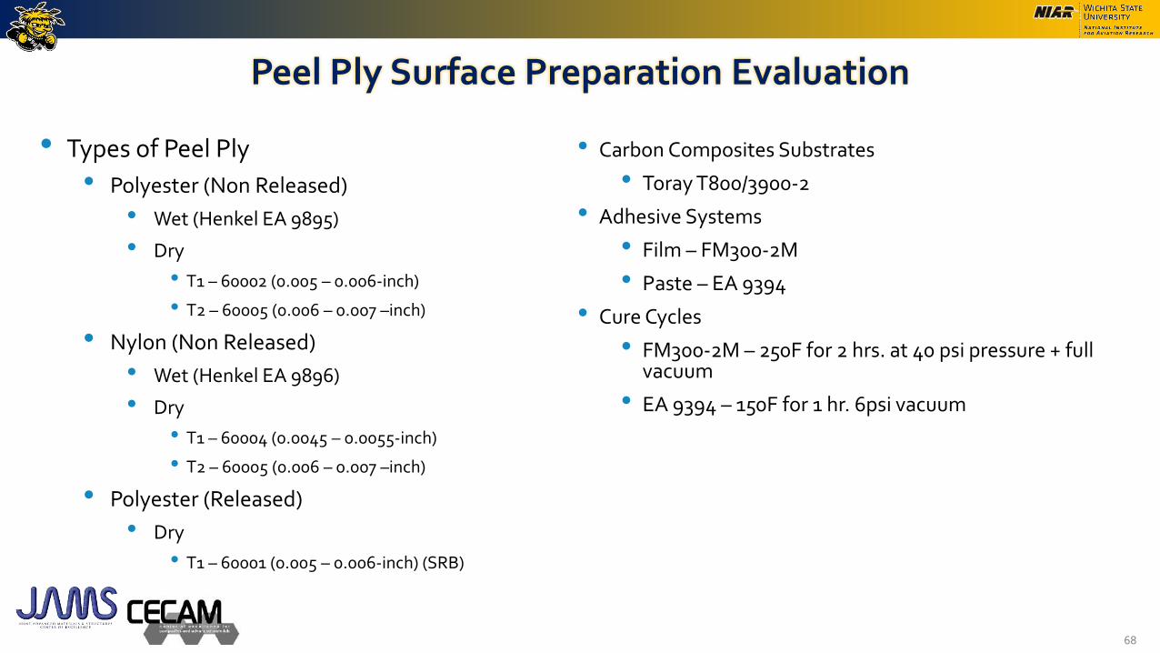
• Types of Peel Ply
• Polyester (Non Released)
• Wet (Henkel EA 9895)
• Dry
• T1 – 60002 (0.005 – 0.006-inch)
• T2 – 60005 (0.006 – 0.007 –inch)
• Nylon (Non Released)
• Wet (Henkel EA 9896)
• Dry
• T1 – 60004 (0.0045 – 0.0055-inch)
• T2 – 60005 (0.006 – 0.007 –inch)
• Polyester (Released)
• Dry
• T1 – 60001 (0.005 – 0.006-inch) (SRB)
68
• Carbon Composites Substrates
• Toray T800/3900-2
• Adhesive Systems
• Film – FM300-2M
• Paste – EA 9394
• Cure Cycles
• FM300-2M – 250F for 2 hrs. at 40 psi pressure + full vacuum
• EA 9394 – 150F for 1 hr. 6psi vacuum
Peel Ply Surface Preparation Evaluation
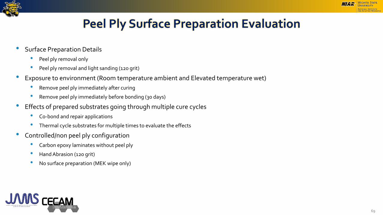
• Surface Preparation Details
• Peel ply removal only
• Peel ply removal and light sanding (120 grit)
• Exposure to environment (Room temperature ambient and Elevated temperature wet)
• Remove peel ply immediately after curing
• Remove peel ply immediately before bonding (30 days)
• Effects of prepared substrates going through multiple cure cycles
• Co-bond and repair applications
• Thermal cycle substrates for multiple times to evaluate the effects
• Controlled/non peel ply configuration
• Carbon epoxy laminates without peel ply
• Hand Abrasion (120 grit)
• No surface preparation (MEK wipe only)
69

Peel Ply Surface Preparation EvaluationMethods of Bond Surface Quality Assessment
• Surface Characterization
• Surface roughness measurements
• Contact angle measurements
• Scanning electron microscopic (SEM) inspection for surface details
• X-ray photoelectron spectroscopy (XPS) to detect surface contamination
• Wettability Envelope Development
70
A
C
D
0
5
10
15
20
25
30
35
40
0 5 10 15 20 25
Dis
per
sive
/ m
N m
-1
Polar / mN m-1
Peel Ply Surface Preparation EvaluationMethods of Mechanical and Physical Property Evaluation
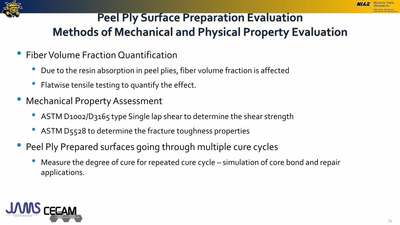
• Fiber Volume Fraction Quantification
• Due to the resin absorption in peel plies, fiber volume fraction is affected
• Flatwise tensile testing to quantify the effect.
• Mechanical Property Assessment
• ASTM D1002/D3165 type Single lap shear to determine the shear strength
• ASTM D5528 to determine the fracture toughness properties
• Peel Ply Prepared surfaces going through multiple cure cycles
• Measure the degree of cure for repeated cure cycle – simulation of core bond and repair applications.
71

Summary of Activities
• Current Activities
• Task 1 – Substrate and adhesive compatibility
• Task 2 – Use of peel ply for composite substrate preparation
• Completed Activities
• Effects of mix-ratio in two part paste adhesives
• Evaluation of assembly time in paste adhesives
• Amine blush effects
• Fluid sensitivity of adhesive
• Efficient adhesive screening method testing.
72

Effects of incorrect mix-ratio in two part paste adhesives
• Two part adhesive for smaller quantities are available in cartridge form. (Mix ratio is not a concern) For applications that require larger quantities, common method is to obtain them in separate containers and manually mix it. It is important to evaluate the sensitivity of mix ratio in these applications
• Experimental Approach – used PAA+BR127 and Abrasion + AC120-2 prepared aluminum and carbon composite substrates and fabricated panels with different mix ratios for Part A and part B. Test methods evaluated are D1002 – single lap shear, mode I fracture toughness, and floating roller peel specimens (selected incorrect mix ratios).
• EA 9394 was used for the study with Part A mix ratio error ranging from -40% to +40%
73
Adhesive Adherend Percent 0.005" Glass Bead
Identification Material Mismatch A [g] B [g] Weight [g]
-40% 30.000 3.060 0.00331
-20% 30.000 4.080 0.00341
0.00351
0.00371
20% 30.000 6.120 0.00361
Adhesive Quantity
EA9394Aluminum
0.063"
40% 30.000 7.140
0% 30.000 5.100

Effects of incorrect mix-ratio in two part paste adhesivesTest Results – Single Lap Shear –ASTM D1002
74
0
500
1000
1500
2000
2500
3000
3500
4000
4500
-40% -20% 0% 20% 40%
Aver
age
Str
ength
[psi
]
Incorrect Mix Ratio – Part A Mismatch
Batch 1 - PAA Batch 2 - AC-130-2
Less than nominal Component B
More than nominal Component B
-40% -20% 0% 20% 40%
Adhesive/Cohesive Failures
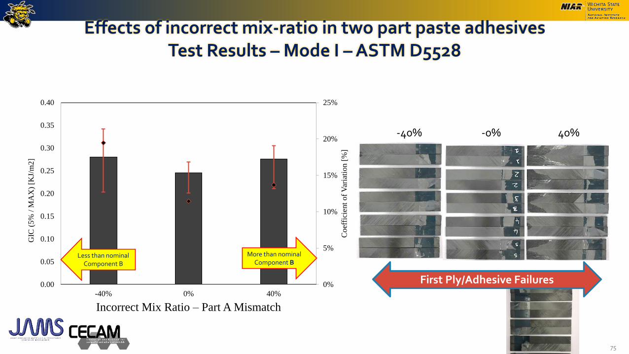
Effects of incorrect mix-ratio in two part paste adhesivesTest Results – Mode I –ASTM D5528
75
0%
5%
10%
15%
20%
25%
0.00
0.05
0.10
0.15
0.20
0.25
0.30
0.35
0.40
-40% 0% 40%
Incorrect Mix Ratio – Part A Mismatch
Coef
fici
ent
of
Var
iati
on [
%]
GIC
(5%
/ M
AX
) [K
J/m
2]
Less than nominal Component B
More than nominal Component B
-40% -0% 40%
First Ply/Adhesive Failures
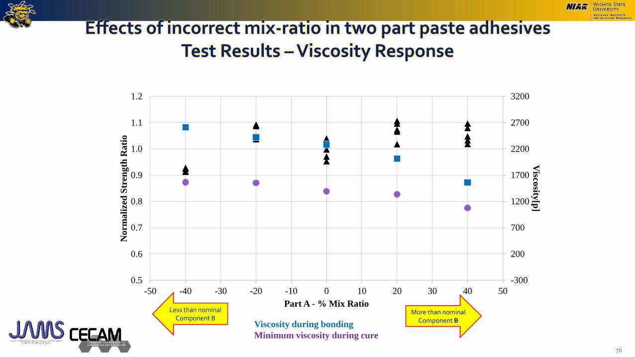
Effects of incorrect mix-ratio in two part paste adhesivesTest Results –Viscosity Response
76
-300
200
700
1200
1700
2200
2700
3200
0.5
0.6
0.7
0.8
0.9
1.0
1.1
1.2
-50 -40 -30 -20 -10 0 10 20 30 40 50
Visco
sity[p
]
No
rma
lize
d S
tren
gth
Ra
tio
Part A - % Mix RatioLess than nominal
Component BMore than nominal
Component BViscosity during bonding
Minimum viscosity during cure

Effects of incorrect mix-ratio in two part paste adhesivesTest results – Summary
• EA9394 adhesive system showed a ~±15% change in the mechanical properties of single lap shear and fracture toughness at the extreme mix ratios between -40% & +40%
• Repeatability of the experiment was validated with a second data set. Data correlates will with the original testing.
• No change in the failure modes was seen between the extreme ends of the experimental procedure.
• Static response of the properties are desirable. However, understanding of the mix ratio effect on fatigue properties needs to be investigated.
77
0.0
0.1
0.2
0.3
0.4
0.5
0.6
0.7
0.8
0.9
1.0
1.1
1.2
1.3
1.4
1.5
-50 -40 -30 -20 -10 0 10 20 30 40 50
No
rma
lize
d P
rop
ert
y
Part A - % Mix Ratio
D1002 - PAA
D1002 - AC-130-2
D5528 - Carbon Fiber Substrates

Evaluation of assembly time in paste adhesives
• Manufacturer provided pot life is to be used as a material specification. In bonding applications, assembly time is defined as the time it takes to mix, apply adhesive and mate the two parts together. Depending on the bond area and the complexity (contour) of the structure, this could be a critical parameter.
• Experimental Approach – used PAA+BR127 and Abrasion + AC120-2 prepared aluminum and carbon composite substrates and fabricated panels with different assembly times. Test methods evaluated are D1002 – single lap shear, mode I fracture toughness, and floating roller peel specimens (selected incorrect mix ratios).
• Assembly time for EA 9394 was varied from 0, 5, 45, 60, 90, and 120 minutes
78

Evaluation of assembly time in paste adhesivesTest Results – Single Lap Shear –ASTM D1002
79
0
500
1000
1500
2000
2500
3000
3500
4000
4500
5MIN 45MIN 60MIN 90MIN 120MIN
Aver
age
Str
ength
[psi
]
Assembly Time [min]
Batch 1 - PAA Batch 2 - AC-130-2
Higher % Adhesive Failures
Adhesive/Cohesive
Cohesive Failures
5 min 45 min 60 min 90 min 120 min

Evaluation of assembly time in paste adhesivesTest Results – Mode I –ASTM D5528
80
0%
10%
20%
30%
40%
50%
60%
70%
80%
90%
0.00
0.05
0.10
0.15
0.20
0.25
5MIN 60MIN 120MIN
Coef
fici
ent
of
Vari
ati
on
[%
]
GIC
(5
% /
MA
X)
[KJ/m
2]
5 min 60 min 120 min
First Ply/Adhesive Failures
Adhesive/Cohesive Failures
Cohesive Failures

Evaluation of assembly time in paste adhesivesTest Results –Viscosity Response
81
0
2000
4000
6000
8000
10000
12000
0.00
0.10
0.20
0.30
0.40
0.50
0.60
0.70
0.80
0.90
1.00
1.10
0 20 40 60 80 100 120 140
Visco
sity [p
]
No
rma
lize
d S
tren
gth
Assembly Time [min]
Viscosity during bonding
Minimum viscosity during cure
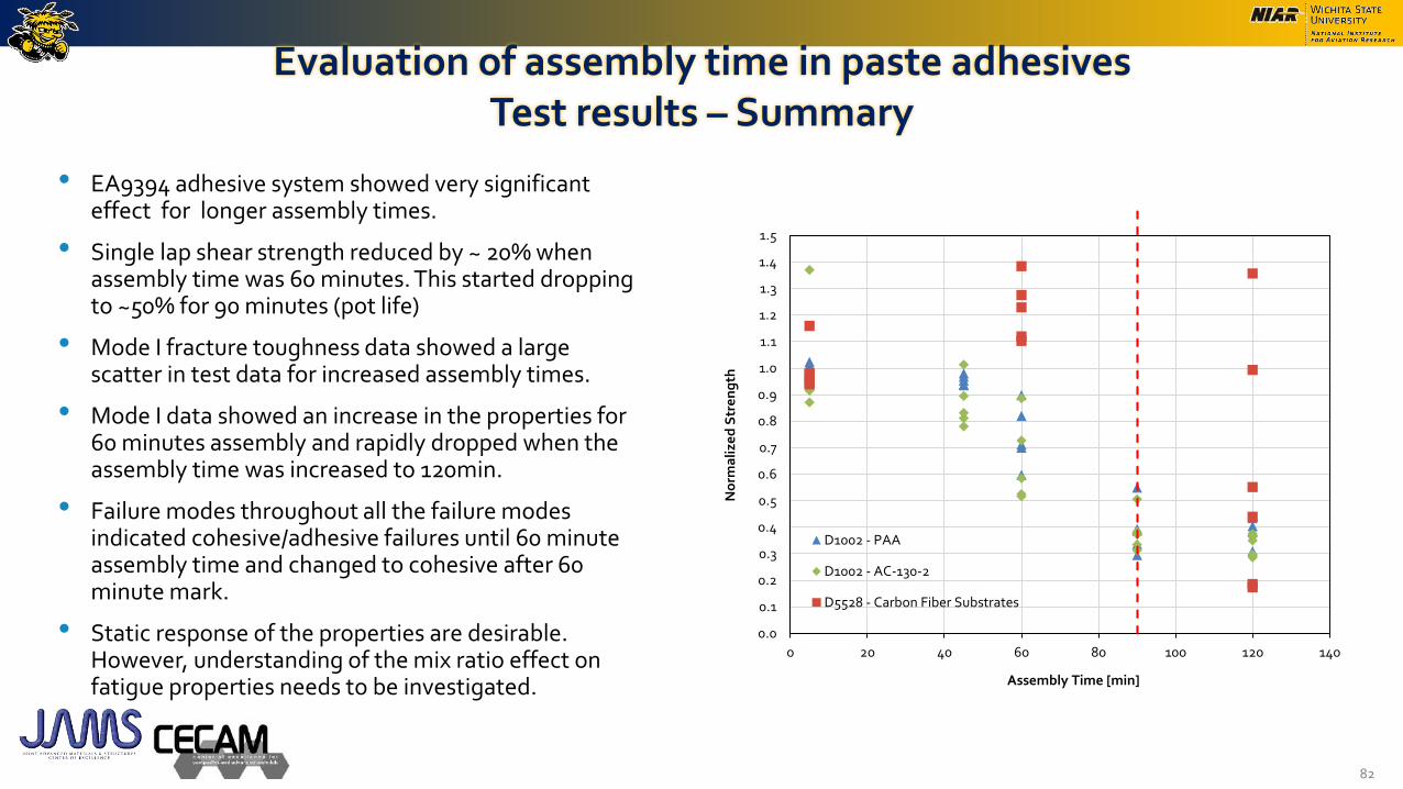
Evaluation of assembly time in paste adhesivesTest results – Summary
• EA9394 adhesive system showed very significant effect for longer assembly times.
• Single lap shear strength reduced by ~ 20% when assembly time was 60 minutes. This started dropping to ~50% for 90 minutes (pot life)
• Mode I fracture toughness data showed a large scatter in test data for increased assembly times.
• Mode I data showed an increase in the properties for 60 minutes assembly and rapidly dropped when the assembly time was increased to 120min.
• Failure modes throughout all the failure modes indicated cohesive/adhesive failures until 60 minute assembly time and changed to cohesive after 60 minute mark.
• Static response of the properties are desirable. However, understanding of the mix ratio effect on fatigue properties needs to be investigated.
82
0.0
0.1
0.2
0.3
0.4
0.5
0.6
0.7
0.8
0.9
1.0
1.1
1.2
1.3
1.4
1.5
0 20 40 60 80 100 120 140
No
rma
lize
d S
tre
ng
th
Assembly Time [min]
D1002 - PAA
D1002 - AC-130-2
D5528 - Carbon Fiber Substrates

Fluid sensitivity of adhesive
• Current method used to evaluate the fluid sensitivity of adhesives is the D1002 single lap shear specimen configurations.
• D1002 Lap Shear specimen configurations requires treated substrate materials which involves numerous steps form preparation to storage.
• The adhesive area exposed to fluids is minimum. (Adhesive Thickness)
• A relatively simpler (test method + specimen geometry) bulk adhesive specimens were fabricated using the adhesive systems and simpler test configuration (3-pt bending) was used to evaluate the effects and compared with the current D1002 method.
• EA 9394 and FM300-2m material systems were used for the evaluation.
• Fluids used in this study
• Skydrol LD-4 (SAE AS1241, Type IV, Class 1) – 90 days
• MEK washing fluid. ASTM D740 – 90 minutes
• 145F/85% Relative Humidity 1000hrs – Controlled Condition
83

Fluid sensitivity of adhesiveTest Results
84
0.0
0.2
0.4
0.6
0.8
1.0
1.2
BASELINE MEK - 90 Minutes Skydrol LD-4 - 90 days Moisture Conditioning
No
rma
lize
d S
tren
gth
3-pt Bend - EA 9394 D1002 - EA 9394
0.0
0.2
0.4
0.6
0.8
1.0
1.2
BASELINE MEK - 90 Minutes Skydrol LD-4 - 90 days Moisture Conditioning
No
rma
lize
d S
tren
gth
3-pt Bend - FM300-2M D1002 - FM300-2M
EA9394 FM300-2M

Adhesive Screening Test Methods
• Currently ASTM D1002 test method is being used to perform screening test/receiving inspections of adhesive material. ASTM D1002 requires a specialized substrates – treated chemical treatment/preparation method.
• As an alternate to this test method/substrate, Epoxyglass G10 substrates has been evaluated to be used in this type of screening testing.
• Different substrate thicknesses has been evaluated as well as a added new test method.
• ASTM D1002 – Al substrates – 0.063-in thick (PAA+BR127)
• ASTM D1002 – Epoxyglass G10 substrates – 0.062-in thick (Abrasion) –Thickness matched
• ASTM D1002 – Epoxyglass G10 substrates – 0.093-in thick (Abrasion) –EI matched
• ASTM D3165 – Epoxyglass G10 substrates – 0.25-in thick (Abrasion) -Standard
• Adhesive systems evaluated
• FM300-2M and EA9394
85
ASTM D1002
ASTM D3165
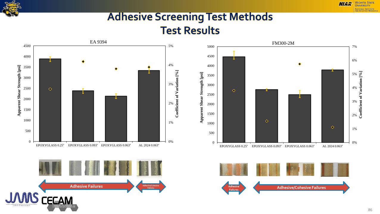
Adhesive Screening Test MethodsTest Results
86
0%
1%
2%
3%
4%
5%
0
500
1000
1500
2000
2500
3000
3500
4000
4500
EPOXYGLASS 0.25'' EPOXYGLASS 0.093'' EPOXYGLASS 0.063'' AL 2024 0.063''
Co
effi
cien
t o
f V
ari
ati
on
[%
]
Ap
pa
ren
t S
hea
r S
tren
gth
[p
si]
EA 9394
0%
1%
2%
3%
4%
5%
6%
7%
0
500
1000
1500
2000
2500
3000
3500
4000
4500
5000
EPOXYGLASS 0.25'' EPOXYGLASS 0.093'' EPOXYGLASS 0.063'' AL 2024 0.063''
Co
effi
cien
t o
f V
ari
ati
on
[%
]
Ap
pa
ren
t S
hea
r S
tren
gth
[p
si]
FM300-2M
Adhesive/Cohesive FailuresAdhesive Failures Adhesive/Cohesive FailuresAdhesive
Failures

Adhesive Screening Test MethodsSummary
• In a receiving inspection/screening tests, it is usually a Pass/Fail criteria
• Epoxyglass substrates can be used for screening/receiving inspection tests. Baseline tests needs to be performed for the identical specimen configurations.
• Higher variation is seen in the bondline thickness for 0.25-inch thick epoxyglass substrates. Bonding process/bondline control mechanism needs to be revisited to get the required bondline thicknesses.
87

Looking Forward
• Future Works
• Generate bond process protocols for
• Selecting compatible substrate and adhesive combinations for a robust bond structure
• Provide guidelines on how to select and use peel ply for composite substrate preparation
• Benefit to Aviation
• Generate bond process protocols
• Provide guidance on the critical parameters in the bond process and how to mechanically test them to generate protocols
88
Acknowledgement
• Advisory Committee and Program Guidance (FAA)
• Cindy Ashforth
• Curt Davies
• Larry Ilcewicz
• Ahmet Oztekin
• Program Support
• Shannon Jones (Textron Aviation)
• Tony Hinman (Solvay)
• John Marsicano (Henkel)
89
• Document Review
• Rachael Andrulonis (NIAR)
• Bryce Floryancic
• Shannon Jones (Textron Aviation)
• Wei Kwan
• Royal Lovingfoss (NIAR)
• Molly Stone
• Mike Stuart (Solvay)