PAPER OPEN ACCESS Related content Deep drawing mechanism ...
1530
Addullah A. Dhaiban, et al., Development of Deep Drawing without Blank -Holder for Producing
Elliptic Brass Cups Through Conical Dies, pp. 1530 - 1548
Corresponding author.
E-mail address: [email protected]
DEVELOPMENT OF DEEP DRAWING WITHOUT BLANK-HOLDER
FOR PRODUCING ELLIPTIC BRASS CUPS THROUGH CONICAL DIES
Abdullah A. Dhaiban*, M-Emad S. Soliman , M.G. El-Sebaie
Department of Mechanical Engineering, Faculty of Engineering, Assiut University
Received 2 June 2013, accepted 18 June 2013
ABSTRACT
This paper introduces a new technique for deep drawing of elliptic cups through a conical die
without blank holder or draw beads. In this technique an elliptical-cup is produced by pushing a
circular blank using a flat-headed elliptic punch through a conical die with an elliptic aperture in a
single stroke. A 3D parametric finite element (FE) model was built using the commercial FE-
package ANSYS/APDL. Effects of die and punch geometry including, half-cone angle, die fillet
radius, die aperture length and punch fillet radius on limiting drawing ratio (LDR), drawing load
and thickness strain of the cup have been investigated. A die with half cone angle of 18° has shown
the best drawability for the new technique. Finite element model results showed good agreement
with experimental results. A die with an aspect ratio of 2 has been used with punches having aspect
ratios ranging from 2 to 2.25. Tensile tests were carried out to obtain the stress -strain behavior for
the used material. A total of seven punches were used for forming sheet metal of brass (CuZn33)
with initial thicknesses of 1.5, 1.9, 2.4 and 3.2 mm at different clearance ratios (c/t). The effects of
blank thickness and clearance ratio on limiting drawing ratio, drawing load and thickness strain
were experimentally investigated. An elliptic cup with a limiting drawing ratio (LDR) of 2.26 has
been successfully achieved.
Keywords: Sheet metal forming, Deep drawing, Conical die, Elliptic cup, FEM, LDR.
1. Introduction
Manufacturing of sheet metal parts by means of press forming is a cost-effective process since it eliminates expensive machining and welding operations giving a better quality finished product[1]. Sheet metal parts are encountered almost everywhere from containers, automotives and buildings to aircrafts. Deep drawing of non-symmetric parts are considered complicated process due to, irregular contact conditions between blank and die, and the different forming characteristic from those of axisymmetric circular deep drawing[2–4]. Deep drawing is one of the widely used sheet metal working processes in industry to produce cup shaped components at a very high production rate[5]. Research about deep drawing without a blank holder, such as conical and tractrix dies, has attracted the attention of many researchers.
At certain ratios of blank diameter to blank thickness (d/t) the flange resistance to buckling and wrinkling is sufficient to eliminate the need for a blank holder. Hasab-Alla[6] mentioned that this ratio can be defined by the value of d/t <50. Deep drawing without blank holder with d/t<40 gives higher LDR’s compared to deep drawing with blank holder. The limiting drawing ratio (LDR) in this case is restricted by wrinkling at the rim of the

1531
Addullah A. Dhaiban, et al., Development of Deep Drawing without Blank -Holder for Producing
Elliptic Brass Cups Through Conical Dies, pp. 1530 - 1548
Journal of Engineering Sciences, Assiut University, Faculty of Engineering, Vol. 41, No. 4, July,
2013, E-mail address: [email protected]
flange or buckling of the cup wall for thin sheets and by fracture at the punch nose area for thick sheets.
In elliptical cup deep drawing, DR is defined by elliptical punch perimeter and the original sheet perimeter[7,8]. Sedighi and Rasti[9] investigated the required drawing forces for flat, conical and tractrix dies versus punch travel along the loading stroke. They showed that the required drawing forces for tractrix and conical dies are less than those required for flat dies. Hasab-Allah [6] conducted research on the deep drawing process of a circular cup on a conical die without blankholder. The investigation showed that, in cases of drawing with 20% simultaneous ironing ratio LDR of soft aluminum using a rough punch was increased to 2.77 compared to 2.5 in the case of drawing without ironing. Hezamet al.[10]developed a new process for producing a square cup through conical die. They reported that square cups with drawing ratios of 2.92 for brass and 2.74 for aluminum were successfully produced.
The finite element simulation of metal forming processes is nowadays a well-established tool for design, production and research in many industries[11–13]. Not only the final forming process but also many other aspects are studied in order to reduce the number of expensive experimental tests in the design of forming setups[11,14]. Chang et al. [15]concluded that the major axis/minor axis, i.e the aspect ratio, of the ellipse affects the stress and strain distributions and formation limits in the deep drawing of elliptic cups. Park et al. [16]studied the effect of variation of punch and die radii to improve the formability of elliptical cups for deep drawing processes. Kim et al. [17]have experimentally investigated the effect of aspect ratio on wrinkling behavior of the elliptical cup deep drawing process. They found that the first fold was generated at an aspect ratio of 1.333. With the increase of aspect ratio of punch, wrinkles formation tended to be stable and close to the area of the major axis.
Huh et al. [18]performed finite element analysis of shell-type element for modeling of an elliptic cup with large aspect ratios up to 2, using LS-DYNA3D in four deep-drawing stages. They found that, there are trends that local deformation will result along the major axis direction, with wrinkles on the minor axis. Yang [19] conducted a FEM for deep drawing of elliptical cups using magnesium alloy at elevated temperature (300 °C) with aspect ratio of 1.6. Huang [8] carried out a FEM and experimental work for drawing of elliptical cups using steel material by hydroforming with aspect ratio of 1.57. He mentioned that elliptic cup with LDR of 2.05 was successfully produced. Many researchers conducted the deep drawing of elliptical cups either in multi-stages [16,18,20,21]or using hydroforming deep drawing process[8,12,22].
In the present study, a new process for deep drawing of elliptical cups without blank holder has been proposed. Finite element analysis has been used to investigate the effect of die and punch geometry on the limiting drawing ratio (LDR) and on the drawing load associated with the new process. Half-cone angle, fillet radius and aperture (throat) length, of the die together with punch fillet radius were optimized for the proposed process.

1532 Addullah A. Dhaiban, et al., Development of Deep Drawing without Blank -Holder for Producing
Elliptic Brass Cups Through Conical Dies, pp. 1530 - 1548
Journal of Engineering Sciences, Assiut University, Faculty of Engineering, Vol. 41, No. 4, July,
2013, E-mail address: [email protected]
2. Deformation mechanism of the proposed method
In the proposed process, an elliptical cup can simply be drawn by pushing a circular blank by a flat-ended elliptic punch through a conical die as shown in Fig. 1. An elliptic aperture has been introduce at the end of the conical die cavity so that the final shape of the drawn cup fits into the elliptic shape of the die cavity.
Fig. 1. Elliptic-cup drawing with circular blank using elliptical punch through an elliptical die
Fig. 2 shows the forming sequence during the drawing process. The first stage in the deep drawing process is the cupping stage, followed by formation of a partially drawn frustum cup, then an elliptic cup drawing stage and finally the formation of the completed elliptic cup. During cupping stage, because of the reduction in the circumferential direction and due to sequential radial cupping action in the conical section of the die, the outer perimeter of the circular blank is subjected to a high compressive circumferential stress. The conical surface of the die cavity supports the blank edge before deformation. In this stage the blank is bent around the corner of the elliptic punch and the blank flange comes into contact with the die wall and conforms to its profile. In the conventional, blank holder, elliptic cup deep drawing, the blank is bent through a right angle as it passes over the die entry radius and then has to be unbent as it travels between punch-die gap. The walls of the cup primarily undergo a longitudinal tensile stress, as the punch transmits the drawing force through the walls of the cup as it is drawn into the die cavity. There is also a tensile hoop stress caused by the cup being held tightly over the punch.
In the proposed process, there is no unbending action. This mechanism helps to produce a less work hardened, partially drawn conical cup (frustum) that has greater ductility in the walls. Therefore, considerable drawing deformation can be achieved immediately after cupping without the need for interstage annealing. Just after a frustum cup is accomplished at the end of the cupping stage, it enters the next stage of deformation, the flat-headed aperture of the conical die, to be drawn into the complete elliptic cup.
Die
Die fillet
Die throat
Circular
blank
Elliptic punch
Elliptic aperture

1533
Addullah A. Dhaiban, et al., Development of Deep Drawing without Blank -Holder for Producing
Elliptic Brass Cups Through Conical Dies, pp. 1530 - 1548
Journal of Engineering Sciences, Assiut University, Faculty of Engineering, Vol. 41, No. 4, July,
2013, E-mail address: [email protected]
a. Cupping
b. Partial
drawing of
frustum cup
c. Drawing of
elliptic cup
d. Completed
elliptic cup
Fig. 2. Sequence of elliptic cup drawing by the present process, through a conical die with an elliptic aperture.
3. Finite element model
In the modeling of the deep-drawing process many complex problems are encountered due to non-linearity, the presence of elasto-plastic transformations and the non-constant boundary conditions of contact with friction. Proper selection of element type, element size, and modeling variables is crucial to the validity of the model.
3.1. ANSYS model description
In the present work, ANSYS 14.0 FEA software has been used for simulating the deep drawing process. ANSYS Parametric Design Language (APDL) is a scripting language that can be used to build the model in terms of variables. Building the model parametrically enables variable changes during the optimization process. In the present study, die half-cone angle, die fillet radius, die aperture (throat) length, and punch fillet radius were optimized using APDL.
3.2. Meshing of the model
Conventional shell elements have to be applied with special care in cases where significant deviation from plane-stress behavior is expected. A more realistic simulation of forming processes can be obtained using solid elements that discretize a non-reduced mechanical model. Compared to shell elements, solid elements require substantially higher computational, pre- and post-processing effort, due to the complexity and size of the models used as shown in Fig. 3. The blank is discretized using (SOLID 185) element. The blank is divided into three regions with (4) elements through thickness direction. The first region under the punch flat base (dead zone) is meshed with coarse mesh. The second region under the punch profile was meshed by element size (0.5) mm on circumferential
Punch
Blank
Die
Drawn cup

1534 Addullah A. Dhaiban, et al., Development of Deep Drawing without Blank -Holder for Producing
Elliptic Brass Cups Through Conical Dies, pp. 1530 - 1548
Journal of Engineering Sciences, Assiut University, Faculty of Engineering, Vol. 41, No. 4, July,
2013, E-mail address: [email protected]
direction with aspect ratio of 1.5. And the third region is meshed by average element size (1) mm on circumferential direction with aspect ratio of 1.5.
The tool set (punch and die) were modeled as rigid bodies. Automatic contact procedure in ANSYS 14.0 was used to model the complex interaction between the blank and tooling. For rigid-flexible (tool set-blank) contact, 3D 8-node quadrilateral target element (TARGE 170) was used to represent 3D target (tool set) surface which was associated with the deformable body (blank) represented by 3D 8-node contact element (CONTA174). The contact and target surfaces constituted a “contact pair”, which was used to represent contact and sliding between the surface of tool set and blank. The coefficients of friction used in simulation, were 0.5 and 0.05, for punch-blank and die-blank contacts respectively.
A displacement load is applied to the key point associated to the pilot node representing the punch movement in negative (Z) direction. The die is constrained in motion in all degrees of freedom at a pilot node located at the base of the die. The blank is constrained by symmetry boundary conditions and the contact with the tool set. Because of symmetry, only a quarter model is sufficient for analysis. The discretized finite element model (FEM) geometry of the tool used in the simulation is shown in Fig. 4.
Fig. 3. Meshing the blank with (SOLID 185)element
Fig. 4. The finite element model of the proposed method
3.2.1 Solution and post processing
Since the forming process is associated with large strain, deformation and shape change, it is hard to obtain a stress distribution. As a result, the total load is applied in a number of increments. It is necessary to activate geometrical non-linearity option (NLGEOM) to update the geometry for each increment (sub-step). In ANSYS, the non-linear solution is based on the Newton- Raphson procedure.
When the metal sheet is drawn through a conical die, the drawing ratio is limited by buckling or wrinkling because no hold-down pressure can be applied to the sheet

1535
Addullah A. Dhaiban, et al., Development of Deep Drawing without Blank -Holder for Producing
Elliptic Brass Cups Through Conical Dies, pp. 1530 - 1548
Journal of Engineering Sciences, Assiut University, Faculty of Engineering, Vol. 41, No. 4, July,
2013, E-mail address: [email protected]
blank[23]. To determine the tearing at the punch corner, simulation was carried out with a 25% limitation on the maximum thinning as the critical fracture criteria.
3.2.2 Material model
Modeling of the material’s behavior is one of the most important factors since the simulation response will mainly depend on how well the structural behavior of the material is represented in the model[5,14,24]. Material model is established using mechanical properties obtained from tensile tests. The MISO (multilinear isotropic) hardening elastic–plastic model available in ANSYS uses the Von Mises yield criteria coupled with an isotropic work hardening assumption. This option is often preferred for large strain analyses. Also MISO has been evaluated in order to define the stress–strain behavior. For the used brass CuZn33 the modulus of elasticity (E) is 100 GPa and Poisson's ratio is 0.35, while the rest of the stress-strain curve modeled by different pairs of stress–strain points as shown in.
Table 1.
True stress-true strain values of the material used for 0° rolling direction
Strain 0.0006 0.001 0.008 0.034 0.065 0.168 0.206 0.252 0.300 0.350 0.408 0.422
Stress
(Mpa) 62 100 154.1 189 220 321.7 357 393.8 427.9 459.9 492.4 496.9
4. Numerical results
4.1. Effects of tool geometry
Finite element simulation was carried out to explore numerically the effects of die and punch geometry, including the effects of die-half cone angle, die fillet radius, die aperture length and punch profile radius. Aspect ratio has a major effect on limiting drawing ratio of elliptical-cups. With increased aspect ratio the limiting drawing ratio is decreased due to advanced wrinkling and excessive thinning close to the area of the major axis. In this study aspect ratios for elliptic punches were ranged from 2 to 2.25, whereas the aspect ratio of the die aperture was taken as a constant value (60/30). The used material is brass CuZn33 with mechanical properties as mentioned in section 5.2.
4.1.1 Effect of half cone angle of die
Fig. 5 shows the variation of the deep drawing force during the entire deep drawing process of the blank with 5 mm punch radius and 10 mm die fillet radius. The figure shows that, the peak drawing force increases with increasing die half cone angle. Also for conical dies with 18° and 10° half cone angles, the peak values of the drawing force are very close, but geometrically the height of the conical die with 10° is greater than that of 18°. This

1536 Addullah A. Dhaiban, et al., Development of Deep Drawing without Blank -Holder for Producing
Elliptic Brass Cups Through Conical Dies, pp. 1530 - 1548
Journal of Engineering Sciences, Assiut University, Faculty of Engineering, Vol. 41, No. 4, July,
2013, E-mail address: [email protected]
means that, using a conical die with 18° half cone angle has a force reduction in comparison with a conical die with greater half cone angle value or a flat die.
Fig. 6 shows wall thickness variations after the drawing process with respect to initial radial distance along the major and minor diameter. It is clear from this figure that thinning at the end of the major and minor axes increases with increasing half cone angle.
Fig. 5. Punch load-displacement curves for a
conical die with half-cone angles (10, 18, 25, 35, 45)° for blank with t=1.9, d= 92 , c/t=1.45
Fig. 6. Thickness strain along the major and
minor axes of an elliptical cup drawing through a conical die with two different
half-cone angles (45° and 18°)
4.1.2 Effect of die throat length
Fig. 7 shows the effect of the die throat length on the maximum punch load for a blank with 5 mm punch radius, 10 mm die radius. It can be noticed that the maximum punch load increases with the increase of the die throat length. Die aperture with 3 mm throat length have been used to ensure good support for the aperture region. The increase in maximum punch load is attributed to the increase of the frictional resistance force at the die throat surface.
4.1.3 Effect of die fillet radius
The intersection profile of the inner surfaces of the die conical portion with the straight elliptic aperture, results in a sharp edge. Therefore an appropriate fillet is important to minimize the stress concentrations at this profile. Fig. 8 shows the effect of the die fillet
0
10
20
30
40
50
60
70
80
0 50 100 150 200 250
Pu
nch
-lo
ad, k
N
Punch-disp., mm
angle_10angle_18angle_25angle_35angle-45
10° 18°
25° 35°
45°
-0.4
-0.3
-0.2
-0.1
0
0.1
0.2
0.3
0.4
0.5
0 10 20 30 40 50
Thic
kne
ss s
trai
n
Initial radial distance from center
Major axis, 45°Major axis, 18°Minor axi, 45°Minor axis, 18°

1537
Addullah A. Dhaiban, et al., Development of Deep Drawing without Blank -Holder for Producing
Elliptic Brass Cups Through Conical Dies, pp. 1530 - 1548
Journal of Engineering Sciences, Assiut University, Faculty of Engineering, Vol. 41, No. 4, July,
2013, E-mail address: [email protected]
-0.4
-0.3
-0.2
-0.1
0
0.1
0.2
0.3
0 10 20 30 40 50
Thik
ne
ss s
trai
n
Initial radial distance from cup centere
Major axis, rp=5 mmMajor axis, rp=0 mmMinor axis, rp=5 mmMinor axis, rp=0 mm
radius for brass with (t=1.9, d= 92, c/t=1.45) on the maximum deep drawing load. Maximum load was found to increase with deceasing die fillet radius.
Effect of punch fillet radiusError! Reference source not found. present the variation of the thickness strain along major and minor axes of an elliptical-cup with two different punch filet radii (rp) of 5 mm and zero mm. Deep drawing process of blank with t=1.9 mm, d = 92 mm, and c/t = 1.05 was analyzed. The figure shows that, the thickness strain along the axes of elliptic cup drawn by punch with 5 mm profile radius is less than thickness strain of elliptic cup drawn by punch without fillet radius.
Fig. 7. Effect of die throat length on maximum punch Load with d=90,
t=1.9 and c/t=0.79
Fig. 8 Effect of die fillet radius on maximum punch Load with t=1.45, d=
92, c/t=1.45
Fig. 9. Effect of the elliptic punch fillet radius on thickness strain along major
and minor axes
125
130
135
140
145
0 2 4 6 8 10
Max
. pu
nch
-Lo
ad, k
N
Throat length, mm
40
42
44
46
48
0 5 10 15 20
Max
. pu
nch
Lo
ad, k
N
Die interface Fillet radius, mm

1538 Addullah A. Dhaiban, et al., Development of Deep Drawing without Blank -Holder for Producing
Elliptic Brass Cups Through Conical Dies, pp. 1530 - 1548
Journal of Engineering Sciences, Assiut University, Faculty of Engineering, Vol. 41, No. 4, July,
2013, E-mail address: [email protected]
5. Experimental procedure
5.1. Test equipment
Experiments were carried out on a 1000-kN universal testing machine, Tinios Olsen Machine Model 290 Display with a data acquisition device. Data acquisition was performed using a system composed of a computer, a data acquisition card and application software, which performs the A/D conversion. The relationship of punch load and punch stroke is plotted and displayed directly on screen and saved on an Excel work sheet for later manipulation.
Fig. 10 shows the deep drawing apparatus which mainly consists of the punch set and the die set. The punch set consists of a punch holder and the punch including a centering part. Centering part is used for positioning the punch concentrically to the die aperture to ensure uniform clearance between the punch and the die aperture. The die set consists of a conical die with 18° half-cone angle with die groove to prevent die rotation. The die and the bottom sets are assembled together and mounted on the base of a hydraulic press. However, punch and punch set are assembled and mounted on the upper movable jaw of the universal testing machine. The bottom set has a side outlet window to facilitate disposal of drawn cups.
A total of seven punches and one die of 41Cr4 steel were produced by machining on computerized numerical control machine (CNC) tool. Tables 2 and 3 show the chemical and mechanical properties of the used material. The punches were hardened by being heated up to 900 °C, kept at this temperature for two hours, then quenched in oil. The final hardness attained a value of 40 Rockwell C.
All produced punches have flat heads with a profile radius of 5 mm, with aspect ratios ranging from 2 to 2.25. The major axes of the seven elliptical punches started at 54 mm and ended with 57 mm with a step of 0.5 mm. Similarly the minor axes ranged from 24 to 27 mm in a step of 0.5 mm.
Fig. 10. Details of the deep-drawing set up
Punch holder
Punch
Die
Die set
Disposal orifice

1539
Addullah A. Dhaiban, et al., Development of Deep Drawing without Blank -Holder for Producing
Elliptic Brass Cups Through Conical Dies, pp. 1530 - 1548
Journal of Engineering Sciences, Assiut University, Faculty of Engineering, Vol. 41, No. 4, July,
2013, E-mail address: [email protected]
The die was designed to have two zones; the first zone is conical while the second is elliptic with a straight throat depth of 3 mm. The nominal major and minor diameters of the elliptic aperture were 60 and 30 mm respectively, with a 5 mm, 45
0 chamfer around the
end of the aperture. The die was hardened by the same method of the punches. Tooling geometrical and lubrication conditions are listed in Table 4.
Table 4
Tool dimensions and lubrication conditions
Die
Half cone angle, degree 18
Elliptic aperture major/minor diameter, mm 60/30
Straight throat length of elliptic portion, mm 3
Fillet radius between conical and elliptic portion, mm 10
Punch
Total length, mm 200
Elliptic length, mm 110
Elliptic concentric position length, mm 10
Profile length, mm 5
Major diameters range, mm 54-57
Minor diameters range, mm 24-27
Lubrication
Punch-blank interface None
Die-blank interface grease
5.1. Sheet metal properties
The material used in this study was brass (CuZn33) sheet with thicknesses of 1.5, 1.9, 2.4 and 3.25 mm. Generally the flow behavior of a material is obtained through the uniaxial tensile test. The tensile specimen prepared according to ASMT E8 with gauge length of 50 mm, initial thicknes 1.9 mm and work zone width of 12.5 mm. Nine specimens have been cut along three different orientations (0°, 45° and 90°) with respect to the rolling direction of the sheet during its manufacturing process. Common tensile properties like true yield stress and true ultimate tensile strength have been obtained from the true stress-strain curve. Yield stress has been calculated by taking the load at 0.2%
Table 2
41Cr4-Chemical composition typical analysis in %
Steel C Si Mn Ph S Cr
41cr4 0.38-0.45 ≤ 0.4 0.6-9 ≤ 0.035 ≤ 0.03 0.9-1.2
Table 3
41Cr4-Mechanical Properties
Yield
stress Ultimate
strength ( Fracture
elongation % Reduction of
area % Impact value
560 MPa 800-950 MPa 11 40 40

1540 Addullah A. Dhaiban, et al., Development of Deep Drawing without Blank -Holder for Producing
Elliptic Brass Cups Through Conical Dies, pp. 1530 - 1548
Journal of Engineering Sciences, Assiut University, Faculty of Engineering, Vol. 41, No. 4, July,
2013, E-mail address: [email protected]
strain by offset method. The load-elongation data obtained from the uniaxial tensile tests were used to calculate the strain hardening exponent (n) and strength coefficient K by assuming that the true stress-true strain curve for the sheet metal follows the power law of hardening in the uniform plastic deformation region. The true stress-strain curves for sheet metal of 1.9 mm thicknessis obtained in simple tension, up to the necking point are shown in Fig. 11.
The normal anisotropy (r) values of sheet metal are usually assessed for longitudinal strains, εl, at (15-25)% strain from the total strain befor initiation of neck. In this study, longitudinal strains of the specimens of about 0.2 were specified for measuring the r values. The properties of the material are shown in Table 5.[24]
Fig. 11. The true stress-true strain curve at different orientations with respect to the
rolling direction (0°, 45° and 90°).
Table 5
Material properties of CuZn33 material
E(GPa)
σy (MPa) σu (MPa) n r △r k
100.5
130.2 484.3 0.39 0.99 -0.20 698.8
5.2. Experimental details
Elliptic-cups have been formed from circular blanks using a test rig installed on a universal testing machine, Tinios Olsen machine Model 290. The machine jaw speed can be controlled from zero up to 1.5 mm/s. However the punch speed selected for all tests was1.15 mm/s. The blanks were lubricated using commercial grease (NAIEXMXD
0
100
200
300
400
500
600
0 0.1 0.2 0.3 0.4 0.5
Tru
e s
tre
ss, M
Pa
True strain, mm/mm
0° wrt rolling direction
45° wrt rolling direction
90° wrt rolling direction
1541
Addullah A. Dhaiban, et al., Development of Deep Drawing without Blank -Holder for Producing
Elliptic Brass Cups Through Conical Dies, pp. 1530 - 1548
Journal of Engineering Sciences, Assiut University, Faculty of Engineering, Vol. 41, No. 4, July,
2013, E-mail address: [email protected]
compatible with international standard ASTM-D-4950-GA and Egyptian standard (ESS) 972-1/8002) on the blank-die interface while the blank-punch interface was kept dry. To prepare blanks, sheets have been cut into square strips approximately 10 mm greater than the required finish size. After that the squares were turned to make circular disks. This ensured that any work hardening effects at the rim of the disk caused by cutting were eliminated. A series of blanks was produced increasing in steps of 1 mm in the diameter.
6. Comparison of numerical and experimental results
6.1. Cup deformation
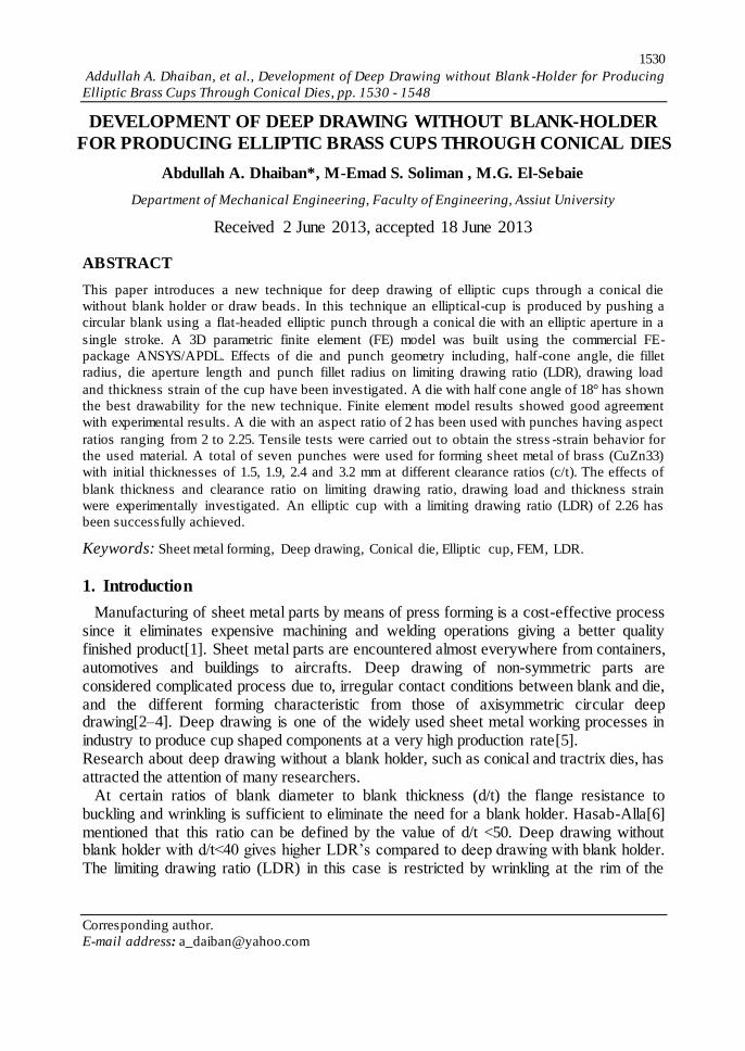
In order to investigate the deformation behavior and view the distortion of grids at cup inside wall, height profile and cross-section of the thickness for the drawn cup, concentric circles of 2 mm spaced out were initially marked on the blank surface. The blank with t=1.9, d=92, and c/t= 1.45 was successfully drawn then cut along the major axis ,with respect to 0
° rolling direction. The cut surface was then carefully polished to give an
accurate cross-section showing the change in thickness and compared with experimental
result as shown in Fig. 12.
(a) (b)
Fig. 12. Grid distortion of (a) experimental drawn cups and (b) numerical obtained by FE
6.2. Load punch-displacement and thickness strain
Fig. 13 compares the finite element and experimental results of punch load-displacement for blank with t=1.9, d= 92, c/t=1.45. Fig. 14 compares the thickness strain along the major and minor axes using finite element model and experimental result for brass with t0 = 1.9 mm, d = 92, c/t = 1.05.

1542 Addullah A. Dhaiban, et al., Development of Deep Drawing without Blank -Holder for Producing
Elliptic Brass Cups Through Conical Dies, pp. 1530 - 1548
Journal of Engineering Sciences, Assiut University, Faculty of Engineering, Vol. 41, No. 4, July,
2013, E-mail address: [email protected]
Fig. 13. Elliptic cup deep drawing load-disp. comparison of FEM with Exp. result for blank with t=1.45, d= 92 ,
c/t=1.45
Fig. 14. Thickness strain along the major and minor axes of an elliptic cup comparison of FEM with Exp. result for
t=1.45, d= 92 , c/t=1.45
It is clear from the Figure that, minimum blank thickness occurs at the contact region at both ends of the major axis of the punch due to the smaller radius of curvature. Therefore blanks experience a maximum tensile stress at the end of the major axis. From figures 14 and 15 the results show that, the finite element models are in good agreement with experimental results.
7. Experimental results and Discussions
Figures 15 to 18 represent the experimental punch load-displacement curves during the deep drawing deformation process for different blank thicknesses and clearance ratios. In general, it could be concluded that all figures show similar trends. Punch load gradually increases as the blank deforms by bending until it reaches the die aperture. Punch load reaches its maximum value when the partially deformed blank enters the throat of the elliptic die. For blank with oversized diameters shown by dotted curves, failure occurs at a load value nearly close to the punch maximum load for t=1.9 mm with c/t =1.45. For other states, maximum punch load occurs at the cupping stage.
Fig. 19 depicts the effect of different die clearance ratio on the punch load. It reflects that, clearance ratio has a large impact on the punch load. It can be also noticed that the punch load before elliptic aperture (during the cupping stage) is not affected by clearance ratio for equal diameter and thickness of blanks. Maximum punch load increase with the decrease of the clearance ratio.
0
10
20
30
40
50
60
0 30 60 90 120 150
Pu
nch
load
, kN
Punch displacement, mm
FEM resultExp. result
-0.3
-0.25
-0.2
-0.15
-0.1
-0.05
0
0.05
0.1
0.15
0.2
0 10 20 30 40 50 60
Thic
kne
ss s
trai
n
Distance from center of the cup, mm
Major axis (FEM)Major axis (Exp.)Minor axis, (FEM)Minor axis (Exp.)

1543
Addullah A. Dhaiban, et al., Development of Deep Drawing without Blank -Holder for Producing
Elliptic Brass Cups Through Conical Dies, pp. 1530 - 1548
Journal of Engineering Sciences, Assiut University, Faculty of Engineering, Vol. 41, No. 4, July,
2013, E-mail address: [email protected]
Fig. 15. Punch load–displacement curves for deep drawing of elliptic cups
(t = 1.5mm, c/t=1.5)
Fig. 16. Punch load–displacement curves for deep drawing of elliptic cups
(t = 1.9mm, c/t=1.45)
Fig. 17. Punch load–displacement curves for
deep drawing of elliptic cups (t=2.4mm, c/t=0.83)
Fig. 18. Punch load–displacement
curves for deep drawing of brass elliptic cups (t=3.2mm, c/t=0.7)
0
5
10
15
20
25
30
35
40
0 20 40 60 80 100 120 140 160
Pu
nch
-lo
ad, k
N
Punch-displacement, mm
Succefull drawing, DR = 2.2
Failed drawing, DR = 2.23
0
10
20
30
40
50
0 20 40 60 80 100 120 140 160
Pu
nch
-Lo
ad, k
N
Punch-displacement, mm
Succefull drawing DR = 2.26
------- Failed drawing, DR = 2.28
0
20
40
60
80
100
120
140
160
180
0 20 40 60 80 100 120 140 160 180
pu
nch
-Lo
ad, k
N
Punch-displacement, mm
Succefull drawing, D.R = 2.17
Failed drawing, D.R = 2.2
0
20
40
60
80
100
120
140
160
180
200
0 20 40 60 80 100 120 140 160
Axi
s Ti
tle
Axis Title
Succefull drawing, D.R = 2.06
Failed drawing, D.R = 2.08

1544 Addullah A. Dhaiban, et al., Development of Deep Drawing without Blank -Holder for Producing
Elliptic Brass Cups Through Conical Dies, pp. 1530 - 1548
Journal of Engineering Sciences, Assiut University, Faculty of Engineering, Vol. 41, No. 4, July,
2013, E-mail address: [email protected]
Fig. 19. Effect of c/t on load-disp. curve for brass with d= 95, t=1.9
shows the combined effect of the clearance ratio and blank thickness on limiting drawing
ratio. It can be noticed that the decrease of clearance ratio improves the LDR in cases of t= 1.9 mm and 2.4 mm. Also the decrease of clearance ratio produces cups with simultaneous ironing with uniform wall thickness.
Error! Reference source not found.shows that the limiting drawing ratio increases for increased blank thickness up to 1.9 mm after that the (LDR) decreases. Maximum (LDR) is obtained using thicknesses between 1.5 and 1.9 mm.
Fig. 21 shows the combined effect of clearance ratio and thickness on maximum drawing load. The figure depicts that the value of maximum load increased with increasing the thickness up to 2.4 mm.
Fig. 20. combined effect of blank
thickness and clearance ratio on limiting drawing ratio (LDR)
Fig. 21. Combined effect of clearance ratio on maximum punch load for
different blank thickness.
2
2.05
2.1
2.15
2.2
2.25
2.3
0.5 1 1.5 2
(LD
R)
c/t
t=1.5
t=1.9
t=2.4
t=3.2 0
50
100
150
200
250
300
0 0.5 1 1.5 2
Max
. Lo
ad,
kN
c/t
t=1.5t=1.9t=2.4t=3.2
0
20
40
60
80
100
120
140
160
180
200
0 20 40 60 80 100 120 140 160 180
Pu
nch
-lo
ad, k
N
Punch-displacement, mm
c/t= 1.05
c/t= 0.92
c/t= 0.79

1545
Addullah A. Dhaiban, et al., Development of Deep Drawing without Blank -Holder for Producing
Elliptic Brass Cups Through Conical Dies, pp. 1530 - 1548
Journal of Engineering Sciences, Assiut University, Faculty of Engineering, Vol. 41, No. 4, July,
2013, E-mail address: [email protected]
Fig. 22 shows photographic picture of successful drawing of elliptic cups. With more ironing, i.e. less clearance ratio, deeper cups are produced with better wall-thickness uniformity and almost no surface irregularities. Thickness surface irregularities are always associated with high clearance ratio. However the disadvantage of lowering clearance ratio is the production of high ears. This disadvantage can be eliminated with optimization of the blank to obtain a cup with uniform height.
(a) t=1.5 mm
(b) t=1.9 mm
(b) t=2.4 mm
(c) t=3.2 mm
Fig. 22. Successfully Drawn cups at Limiting drawing ratio for (a) t=1.5, (b) t=1.9, (c) t=2.4 and (d) t=3.2 at various clerance ratios (c/t)
8. Conclusions
In this paper a new process is introduced for producing elliptic cups using a simple tooling set without blankholder or draw beads in single-acting stroke.
c/t= 1
c/t= 1.33 c/t= 1.5
c/t= 0.79
c/t= 0.92
c/t= 1.05
c/t= 1.45
c/t= 0.73
c/t= 0.83
c/t= 1.05
c/t= 0.7
c/t= 0.78
c/t= 0.9

1546 Addullah A. Dhaiban, et al., Development of Deep Drawing without Blank -Holder for Producing
Elliptic Brass Cups Through Conical Dies, pp. 1530 - 1548
Journal of Engineering Sciences, Assiut University, Faculty of Engineering, Vol. 41, No. 4, July,
2013, E-mail address: [email protected]
The experimental tooling set is built with the aid of finite element simulation to obtain the optimum die half- cone angle, die fillet radius, die aperture length, and punch fillet radius. A die with half cone angle of 18°and die aperture length of 3 mm has shown the best drawability for the new technique. The simulated punch load-displacement and thickness strain distribution of the elliptical cup deep drawing process were conducted and showed a good agreement with the experimental results. Maximum thickness strain is inversely proportional to the punch fillet radius used. The maximum strain value is occurred at the region in the neighborhood of the ends of the major axis of the punch. The effects of blank thickness and clearance on the LDR and punch load are experimentally investigated and the results are discussed. An elliptic cup with an LDR up to 2.26 was successfully achieved. These LDRs are significantly higher than that obtained by conventional techniques and very close to those obtained with complicated non- conventional techniques. The present technique appears to be convenient for drawing sheets of thicknesses between 1.5 and 2mm. High ears were produced in conjunction with the deep cups produced from circular blank with small values of c/t. This disadvantage can be eliminated with optimization of the blank to obtain a cup with uniform height.
9. References
[1] Saxena R. K., and Dixit P. M., 2011, “Numerical analysis of damage for prediction of
fracture initiation in deep drawing,” Finite Elements in Analysis and Design, 47, pp. 1104–
1117.
[2] Seo Y., and Ulintz P., “Formation of a Non-symmetric Part and Blank Optimization Using
Finite Element Analysis,” pp. 1–14.
[3] Park D. H., Huh Y. M., and Kang S. S., 2002, “Study on punch load of non -aximetric deep
drawing product according to blank shape,” Journal of Materials Processing Technology,
130-131, pp. 89–94.
[4] Ku T. ., Ha B. ., Song W. J., Kang B. ., and Hwang S. M., 2002, “Finite element analysis of
multi-stage deep drawing process for high-precision rectangular case with extreme aspect
ratio,” Journal of Materials Processing Technology, 130-131, pp. 128–134.
[5] Kishor N., and Kumar D. R., 2002, “Optimization of initial blank shape to minimize earing
in deep drawing using finite element method,” Journal of Materials Processing Technology,
130-131, pp. 20–30.
[6] Hasab-Alla I. M., 1993, “A finite element simulation and experimental verification of the
deep drawing of sheet metals without blankholder with simultaneous corrective ironing,”
Ph.D thesis, Assiut university, Egypt.
[7] Huang Y., and Lu S., 2011, “Analysis of elliptical cup drawing process of stainless sheet
metal,” Transactions of Nonferrous Metals Society of China, 21(2), pp. 371–377.
[8] Huang Y., 2012, “An analysis of the elliptical cup hydraulic drawing process,” Computer-
Aided Design and Applications, 9(3), pp. 375–383.
[9] Sedighi M., and Rasti M., 2008, “An investigation on manufacturing process parameters of
CNG pressure vessels,” Int J Adv Manuf Technol, pp. 958–964.
[10] Hezam L. M. A., Hassan M. A., Hassab-Allah I. ., and El-Sebaie M. G., 2009,
“Development of a new process for producing deep square cups through conical dies,”
International Journal of Machine Tools and Manufacture, 49(10), pp. 773–780.
1547
Addullah A. Dhaiban, et al., Development of Deep Drawing without Blank -Holder for Producing
Elliptic Brass Cups Through Conical Dies, pp. 1530 - 1548
Journal of Engineering Sciences, Assiut University, Faculty of Engineering, Vol. 41, No. 4, July,
2013, E-mail address: [email protected]
[11] Schwarze M., Vladimirov I. N., and Reese S., 2011, “Sheet metal forming and springback
simulation by means of a new reduced integration solid-shell finite element technology,”
Computer Methods in Applied Mechanics and Engineering, 200(5-8), pp. 454–476.
[12] Lin C., and Kwan C.-T., 2009, “Application of abductive network and FEM to predict the
optimal blank contour of an elliptic cylindrical cup from deep drawing,” journal of materials
processing technology, 9(3), pp. 1351–1361.
[13] Menezes L. F., and Teodosiu C., 2000, “Three-dimensional numerical simulation of the
deep-drawing process using solid fnite elements,” Journal of Materials Processing
Technology, 97, pp. 100–106.
[14] Arriaga A., Lazkano J. M., Pagaldai R., Zaldua A. M., Hernandez R., Atxurra R., and
Chrysostomou A., 2007, “Finite-element analysis of quasi-static characterisation tests in
thermoplastic materials : Experimental and numerical analysis results correlation with
ANSYS,” Polymer Testing, 26, pp. 284–305.
[15] Chang Z., Ma Y., Huang S., and Jiang K., 1994, “Deep drawing process analysis of elliptic
cups by rigid-plastic FEM,” Transactions of NFsoc, 4(2), pp. 61–64.
[16] Park D. H., Kang S. S., and Park S. B., 2001, “A study on the improvement of formability
for elliptical deep drawing processes,” Journal of Materials Processing Technology, 113, pp.
662–665.
[17] Kim J. B., Yoon J. W., Yang D. Y., and Barlat F., 2001, “Investigation into wrinkling
behavior in the elliptical cup deep drawing process by fnite element analysis using
bifurcation theory,” Journal of Materials Processing Technology, 111, pp. 170–174.
[18] Huh H., Kim S., and Kim S., 2000, “Process design for mu lti-stage elliptic cup drawing
with the large aspect ratio,” European Congress on Computational Methods in Applied
Sciences and Engineering, Barcelona, 11-14 September 2000, pp. 11–14.
[19] Yang T. S., 2008, “Finite element analysis of elliptic cup deep drawing of magnesium alloy
sheet,” Jornal of Achievements in Materials and Manufacturing Engineering, 27(2), pp.
139–142.
[20] Kang S. S., Park D. H., Choi B. K., and Park S. B., 2001, “Development of an automated
process sequence design system for multistage elliptical-shaped deep drawing products,”
Metals and Materials, 7(2), pp. 2–3.
[21] Park D. H., and Yarlagadda P. K. D. V, 2008, “Effects of punch load for elliptical deep
drawing product of automotive parts,” International Journal Advanced Manufacturing
Technology, pp. 814–820.
[22] Hama T., Hatakeyama T., Asakawa M., Amino H., Makinouchi A., Fujimoto H., and
Takuda H., 2007, “Finite-element simulation of the elliptical cup deep drawing process by
sheet hydroforming,” Finite Elements in Analysis and Design, 43(3), pp. 234–246.
[23] Narayanasamy R., and Sowerby R., 1995, “Wrinkling behaviour of cold -rolled sheet metals
when drawing through a tractrix die,” Journal of Materials Processing Technology, 49, pp.
199–211.
[24] Goedel V., and Merklein M., 2011, “Variation of deep drawing steel grades ’ properties in
dependency of the stress state and its impact on FEA,” Int. Journal of Materials forming, pp.
183–192.
1548 Addullah A. Dhaiban, et al., Development of Deep Drawing without Blank -Holder for Producing
Elliptic Brass Cups Through Conical Dies, pp. 1530 - 1548
Journal of Engineering Sciences, Assiut University, Faculty of Engineering, Vol. 41, No. 4, July,
2013, E-mail address: [email protected]
السحب العميق بدون مثبت إلنتاج الكؤوس عملية تطوير
قوالب مخروطيهالبيضاوية من مادة النحاس األصفر خالل
الملخص العربي
جديد في السحب العميق للكؤوس البيضاوية خالل قالب مخروطي وبدون ماسك ألسلوبيقدم هذا البحث
بسنبك بيضاويالكأس البيضاوي بدفع قرص دائري أنتاجمخدات تثبيت. يتم في هذا األسلوب أقراص أو الشكل مسطح الرأس خالل قالب مخروطي ذو مخرج بيضاوي وبشوط واحد.
وتم (ANSYS APDL)باستخدام طريقة العناصر المحدودة باستخدام برنامج األبعادتم بناء نموذج ثالثي
الهندسية للقالب والمكبس شامال تأثير ما يلي: نصف زاوية القالب المخروطي ونصف األبعادالتحقق من تأثير ، السنبكمخرج القالب البيضاوي وكذلك نصف قطر تدوير حافة رأس القالب وطولر تدوير التقاء سطحي قط
في هذا األسلوب باستخدام قالب بنصف قابلية للسحب أفضلعلى النسبة القصوى للسحب العميق. و كانت نتائج العملية.نتائج نموذج العناصر المحدودة تطابقًا جيدًا مع الأثبتت كما °. 82زاوية مخروط
( مع مجموعة 8( للبيضاوي بقيمة )األصغرالقطر إلىالقطر األكبر ُاستخدم في الدراسة العملية قالب بنسبة )
و اإلجهاداختبارات الشد للحصول على منحنى إجراء( .تم 8.82 إلى 8تتراوح هذه النسبة فيها من ) سنابكمختلفة لتشكيل مادة النحاس األصفر بأبعاد سنابكة االنفعال للمادة المستخدمة.عمليا تم استخدام سبع
(CuZn33) ( مم وعند نسب خلوص مختلفة. تم 1.5 ,1.9 ,2.4 ,3.2) لألقراصوبسماكات أولية متعددةسمك القرص ونسبة الخلوص في نسبة السحب القصوى وفي حمل السحب وكذلك في تأثيرالتحقق عمليا من
.8.82ح كأس بيضاوي بنسبة سحب قصوى انفعال سمك القرص. تم السحب بنجا