Addressing Climate Change through Carbon Capture and Geological Sequestration in Michigan Dave...
89
Addressing Climate Change through Addressing Climate Change through Carbon Capture and Geological Sequestration Carbon Capture and Geological Sequestration in Michigan in Michigan Dave Barnes We Can Do It Here! We Can Do It Here! 2009 Mid-America Regulatory Conference June 15, 2009
-
Upload
raymundo-nicolas -
Category
Documents
-
view
217 -
download
0
Transcript of Addressing Climate Change through Carbon Capture and Geological Sequestration in Michigan Dave...

Addressing Climate Change throughAddressing Climate Change throughCarbon Capture and Geological Carbon Capture and Geological
SequestrationSequestrationin Michigan in Michigan
Dave BarnesWe Can Do It We Can Do It Here!Here!
2009 Mid-America Regulatory ConferenceJune 15, 2009

2
The Dance of the 3 E’sThe Dance of the 3 E’s(with a nod to Scott Tinker, (with a nod to Scott Tinker,
TBEG)TBEG)

3
US Energy Flow, US Energy Flow, 2007 2007
(Quadrillion BTU’s, (Quadrillion BTU’s, QuadsQuads))
From:US – Energy Information Agency(EIA)
2007

4
}
Efforts To Cap Near-term Efforts To Cap Near-term (<100 Years) Atmospheric CO(<100 Years) Atmospheric CO22
Concentrations Concentrations @ 550 ppmv @ 550 ppmv
Green House Gas Emissions and Energy-Technology Enabling SystemsGreen House Gas Emissions and Energy-Technology Enabling SystemsTheThe Silver BuckshotSilver Buckshot

Governor Jennifer Granholm’s State of the State Address,
Feb 3, 2009• “So here’s our next aggressive goal: By the year
2020, Michigan will reduce our reliance on fossil fuels for generating electricity by 45 percent. We will do it through increased renewable energy, gains in energy efficiency and other new technologies. You heard me right: a 45 percent reduction by 2020.”
• “How will we reach this 45-by-20 goal and get the jobs that come with it? Instead of spending nearly $2 billion a year importing coal or natural gas from other states we’ll be spending our energy dollars on Michigan wind turbines, Michigan solar panels, Michigan energy-efficiency devices, all designed, manufactured and installed by. . .Michigan workers.”

The New Energy Economy – US Energy Systems
• The goal of rapidly transforming US Fossil Fuel Intensive energy infrastructure to a low/no GHG emissions infrastructure is a formidable challenge
2007 EIA

Electric Power Consumption of Coal by Region, 2008
U.S. Total = 1,041.6 (-0.3%)
Million Short Tons (Percent Change from 2007)

Michigan Electric Power Generation, by fuel
Wind Powerin Michigan

9
Carbon Capture and Storage, Carbon Capture and Storage, CCSCCS
• CCS is various methods for capturing and permanently storing anthropogenic CO2 that would otherwise contribute to global climate change.
Global Carbon Cycle (Billion Metric Tons, Gt, Carbon)

10
Geological Sequestration Geological Sequestration ((GS)GS)
• Geological media suitable for storage of CO2 in Michigan
– depleted oil reservoirs (+/- CO2/EOR) and
– deep, saline (brine-filled) reservoir formations
`
`
CO2CRC

11
Michigan’s Deep GS Michigan’s Deep GS Injection ZonesInjection Zones
As much as 16,000ft of bedrock sedimentary strata (below glacial drift)
“Deep” Sandstone
Injection and Confinement Zones
“Shallow” Carbonate and Sandstone
Injection and Confinement Zones
“Intermediate“ Carbonate Reef
Injection and Confinement Zones
MI Storage Potential
~40GtMI Emissions
~93Mt/yr
}

12
Michigan Pilot Injection Test Michigan Pilot Injection Test ProjectProject
•MRCSP is one of seven U.S. DOE/NETL RCSP’s.•Eight-state region of IN, KY, MD, MI, NY, OH, PA, and WV.•Phase I Launched, fall 2003; Phase II commenced October 2005.•Michigan Basin site is one of three small scale CO2 injection test sites.
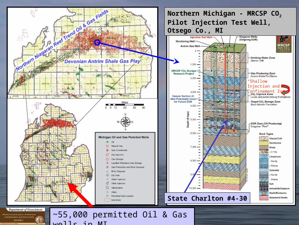
Northern Michigan - MRCSP CO2 Pilot Injection Test Well, Otsego Co., MI
State Charlton #4-30
~55,000 permitted Oil & Gas wells in MI
“Shallow” Injection and Confinement Zone

Northern Michigan Pilot Injection Test Northern Michigan Pilot Injection Test Project; Otsego Co, MIProject; Otsego Co, MI

15
Results of Pilot COResults of Pilot CO22 Injection Injection TestTest• Initial ~20 days of CO2 injection:
>10,000 mt
• Variable injection rates to pipeline capacity: @600mt/day
• Annualized injection rates: ~220,000 mt/yr
• Data extrapolation suggest maximum injection rates: 440-660,000 mt/year
• Additional CO2 of are being injected into the reservoir zone:
50,000 metric tons
Analysis and interpretations of injection data by: Joel Sminchak, Battelle Memorial

16
““Deep” Deep” Sandstone Sandstone
Injection and Injection and Confinement Confinement
ZonesZonesIn Michigan In Michigan
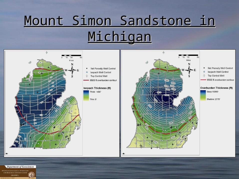
Mount Simon Sandstone in Mount Simon Sandstone in MichiganMichigan

18
““Deep” Injection and Confinement Deep” Injection and Confinement Zones; Zones;
Ottawa Co. Michigan Ottawa Co. Michigan
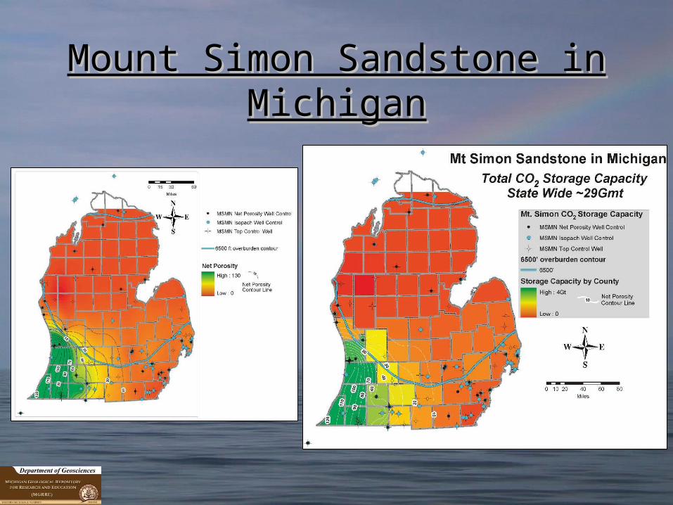
Mount Simon Sandstone in Mount Simon Sandstone in MichiganMichigan

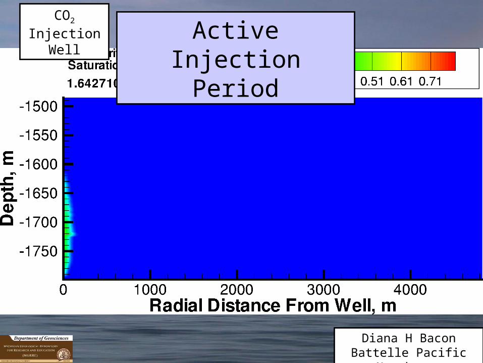
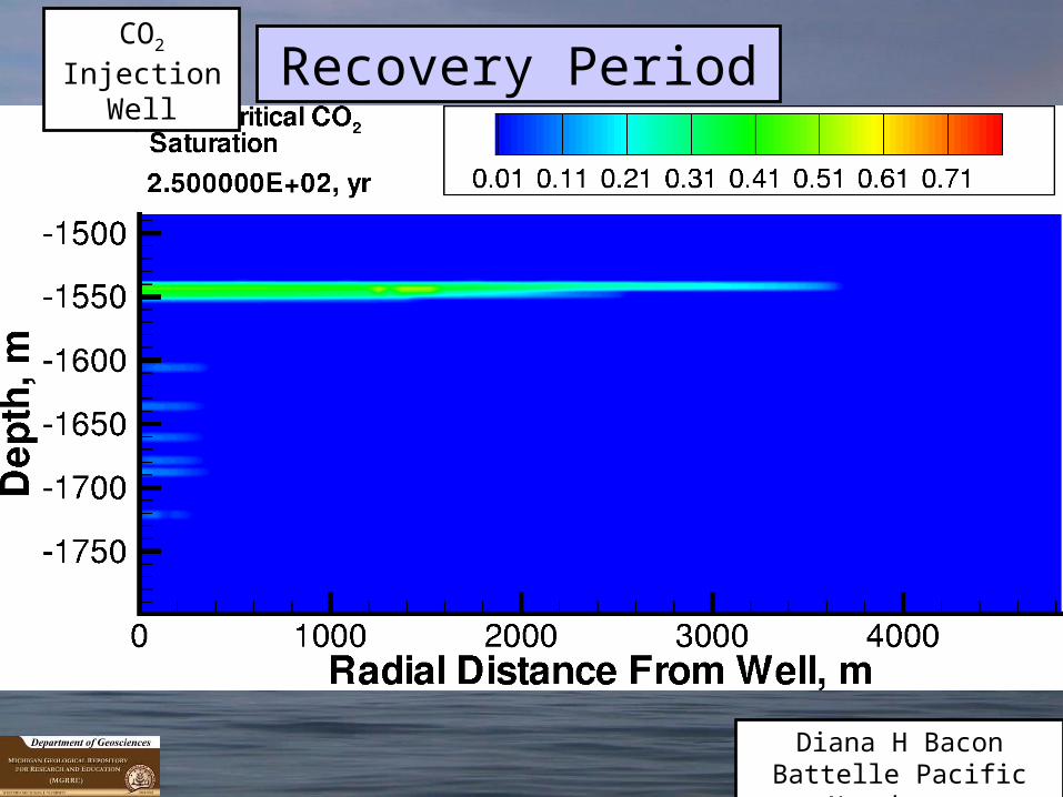
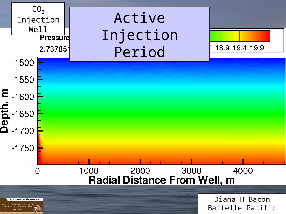
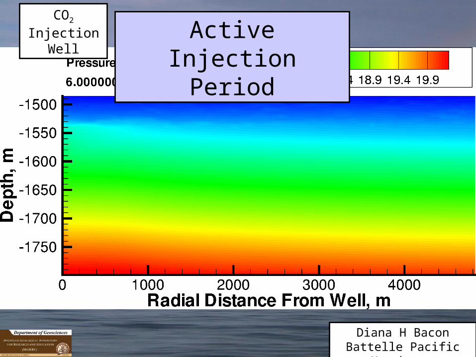
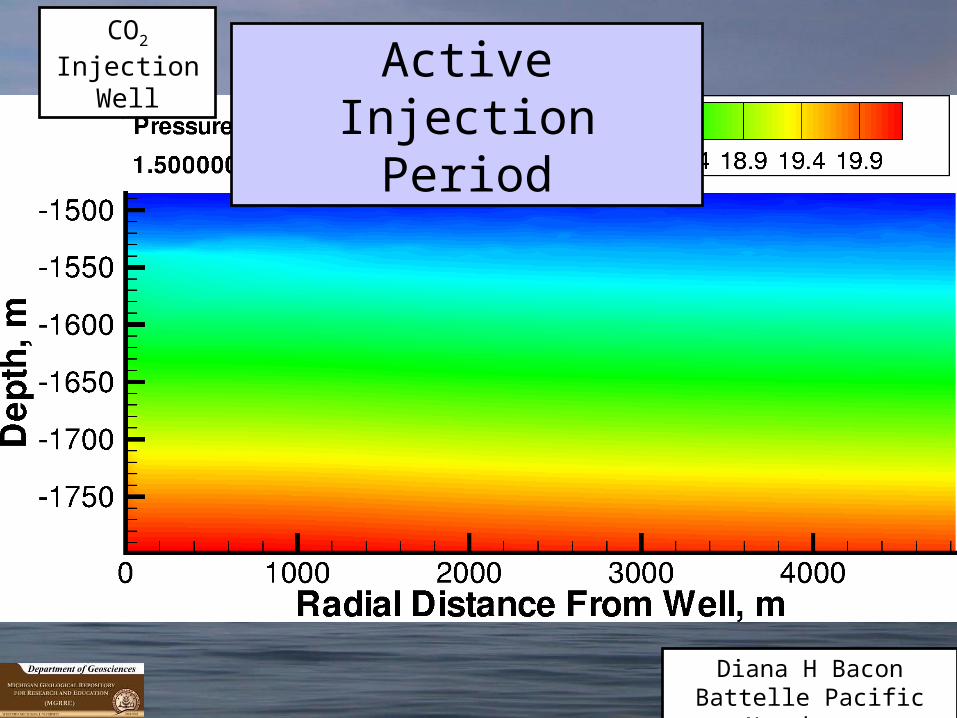
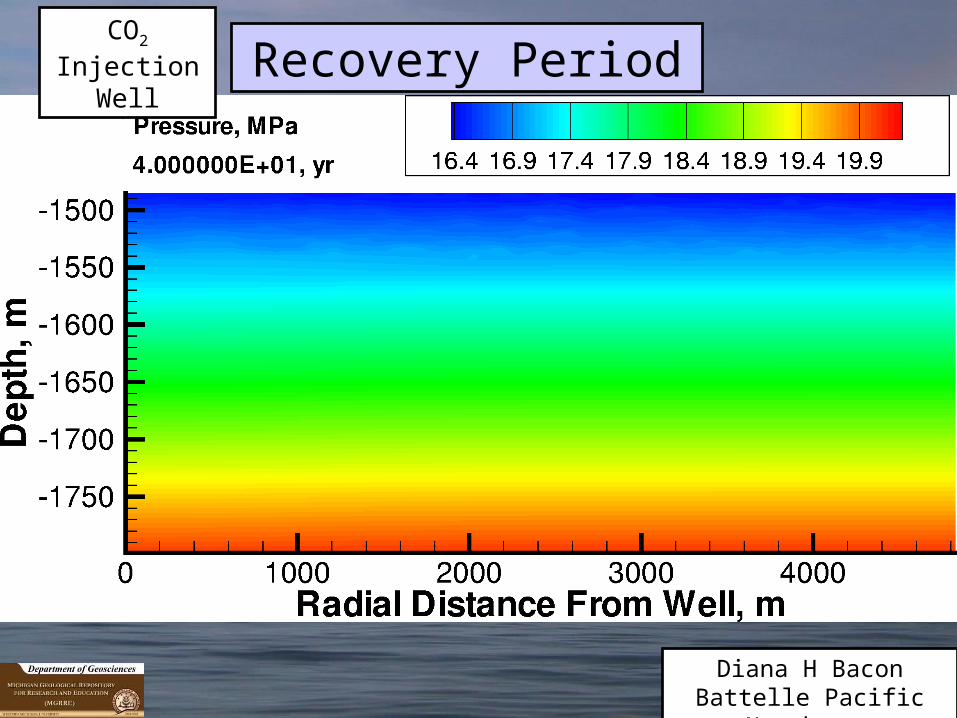
COCO22 Injection Simulation Modeling for a Injection Simulation Modeling for a Large Stationary Point Source (~80Mw)Large Stationary Point Source (~80Mw)
20 yr Active Injection; 280 year Recovery Model 20 yr Active Injection; 280 year Recovery Model ParametersParameters
• Injection Rate = 0.6 MMT/year for 20 yrs
• Recovery Period = 280 years
• Target Formation Interval: 1504-1799 m
• Injection Interval: 1707-1765 m
• Well Diameter: 8 5/8” casing
• Hydrostatic Gradient: 0.49 psi/ft
• Temperature: 50°C
• Brine: 300,000 ppm TDS
• Maximum Entrapped CO2 Saturation = 0.2
Diana H BaconBattelle Pacific
Northwest

CO2 Injection
WellActive Injection
Period
Diana H BaconBattelle Pacific
Northwest

CO2 Injection
WellActive Injection
Period
Diana H BaconBattelle Pacific
Northwest

CO2 Injection
WellActive Injection
Period
Diana H BaconBattelle Pacific
Northwest

CO2 Injection
WellActive Injection
Period
Diana H BaconBattelle Pacific
Northwest
CO2 Injection
WellActive Injection
Period
Diana H BaconBattelle Pacific
Northwest

CO2 Injection
WellActive Injection
Period
Diana H BaconBattelle Pacific
Northwest

CO2 Injection
WellActive Injection
Period
Diana H BaconBattelle Pacific
Northwest

CO2 Injection
WellActive Injection
Period
Diana H BaconBattelle Pacific
Northwest

CO2 Injection
WellActive Injection
Period
Diana H BaconBattelle Pacific
Northwest

CO2 Injection
WellActive Injection
Period
Diana H BaconBattelle Pacific
Northwest

CO2 Injection
WellActive Injection
Period
Diana H BaconBattelle Pacific
Northwest

CO2 Injection
WellActive Injection
Period
Diana H BaconBattelle Pacific
Northwest

CO2 Injection
WellActive Injection
Period
Diana H BaconBattelle Pacific
Northwest

CO2 Injection
WellActive Injection
Period
Diana H BaconBattelle Pacific
Northwest

CO2 Injection
WellActive Injection
Period
Diana H BaconBattelle Pacific
Northwest

CO2 Injection
WellActive Injection
Period
Diana H BaconBattelle Pacific
Northwest

CO2 Injection
WellActive Injection
Period
Diana H BaconBattelle Pacific
Northwest

CO2 Injection
WellActive Injection
Period
Diana H BaconBattelle Pacific
Northwest

CO2 Injection
WellActive Injection
Period
Diana H BaconBattelle Pacific
Northwest

CO2 Injection
WellRecovery Period
Diana H BaconBattelle Pacific
Northwest

CO2 Injection
WellRecovery Period
Diana H BaconBattelle Pacific
Northwest

CO2 Injection
WellRecovery Period
Diana H BaconBattelle Pacific
Northwest

CO2 Injection
WellRecovery Period
Diana H BaconBattelle Pacific
Northwest

CO2 Injection
WellRecovery Period
Diana H BaconBattelle Pacific
Northwest

CO2 Injection
WellRecovery Period
Diana H BaconBattelle Pacific
Northwest

CO2 Injection
WellRecovery Period
Diana H BaconBattelle Pacific
Northwest
CO2 Injection
WellRecovery Period
Diana H BaconBattelle Pacific
Northwest

CO2 Injection
WellRecovery Period
Diana H BaconBattelle Pacific
Northwest

CO2 Injection
WellRecovery Period
Diana H BaconBattelle Pacific
Northwest
CO2 Injection
WellRecovery Period
Diana H BaconBattelle Pacific
Northwest

CO2 Injection
WellRecovery Period
Diana H BaconBattelle Pacific
Northwest

CO2 Injection
Well
Diana H BaconBattelle Pacific
Northwest
Active Injection Period

Diana H BaconBattelle Pacific
Northwest
CO2 Injection
WellActive Injection
Period
Diana H BaconBattelle Pacific
Northwest
CO2 Injection
WellActive Injection
Period

Diana H BaconBattelle Pacific
Northwest
CO2 Injection
WellActive Injection
Period

Diana H BaconBattelle Pacific
Northwest
CO2 Injection
WellActive Injection
Period

Diana H BaconBattelle Pacific
Northwest
CO2 Injection
WellActive Injection
Period

Diana H BaconBattelle Pacific
Northwest
CO2 Injection
WellActive Injection
Period

Diana H BaconBattelle Pacific
Northwest
CO2 Injection
WellActive Injection
Period

Diana H BaconBattelle Pacific
Northwest
CO2 Injection
WellActive Injection
Period

Diana H BaconBattelle Pacific
Northwest
CO2 Injection
WellActive Injection
Period

Diana H BaconBattelle Pacific
Northwest
CO2 Injection
WellActive Injection
Period

Diana H BaconBattelle Pacific
Northwest
CO2 Injection
WellActive Injection
Period

Diana H BaconBattelle Pacific
Northwest
CO2 Injection
WellActive Injection
Period

Diana H BaconBattelle Pacific
Northwest
CO2 Injection
WellActive Injection
Period

Diana H BaconBattelle Pacific
Northwest
CO2 Injection
WellActive Injection
Period
Diana H BaconBattelle Pacific
Northwest
CO2 Injection
WellActive Injection
Period

Diana H BaconBattelle Pacific
Northwest
CO2 Injection
WellActive Injection
Period

Diana H BaconBattelle Pacific
Northwest
CO2 Injection
WellActive Injection
Period

Diana H BaconBattelle Pacific
Northwest
CO2 Injection
WellActive Injection
Period

Diana H BaconBattelle Pacific
Northwest
CO2 Injection
WellActive Injection
Period
Diana H BaconBattelle Pacific
Northwest
CO2 Injection
WellActive Injection
Period

Diana H BaconBattelle Pacific
Northwest
CO2 Injection
WellActive Injection
Period

Diana H BaconBattelle Pacific
Northwest
CO2 Injection
WellRecovery Period

Diana H BaconBattelle Pacific
Northwest
CO2 Injection
WellRecovery Period
Diana H BaconBattelle Pacific
Northwest
CO2 Injection
WellRecovery Period

Diana H BaconBattelle Pacific
Northwest
CO2 Injection
WellRecovery Period

Diana H BaconBattelle Pacific
Northwest
CO2 Injection
WellRecovery Period

Diana H BaconBattelle Pacific
Northwest
CO2 Injection
WellRecovery Period

Diana H BaconBattelle Pacific
Northwest
CO2 Injection
WellRecovery Period

Diana H BaconBattelle Pacific
Northwest
CO2 Injection
WellRecovery Period

Diana H BaconBattelle Pacific
Northwest
CO2 Injection
WellRecovery Period

Diana H BaconBattelle Pacific
Northwest
CO2 Injection
WellRecovery Period

Diana H BaconBattelle Pacific
Northwest
CO2 Injection
WellRecovery Period

Diana H BaconBattelle Pacific
Northwest
CO2 Injection
WellRecovery Period

86
COCO2 2 Injection Simulation Injection Simulation ModelingModeling
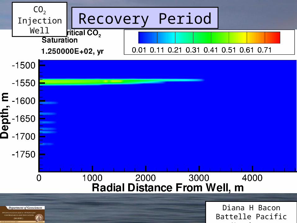
Summary of Preliminary Summary of Preliminary ResultsResults• ½ space 2D Plume Dimensions after 300 years
(20 years active injection, 280 years recovery) = ~3.8 km (2.3 mi)
• Active injection period lateral flow rate (~1.8 km/20yr) = ~90 m/yr
• Recovery period lateral flow rate (~2.0 km/280yr) = ~7.1 m/yr
Diana H BaconBattelle Pacific
Northwest

87
COCO2 2 Injection Simulation Injection Simulation ModelingModeling
Summary of Preliminary Summary of Preliminary ResultsResults• Little dissolved CO2
– Due to high formation fluid salinity
– Minimal perturbation of formation fluid reactivity
• Minimal formation pressure perturbation; rapid re-equilibration
Diana H BaconBattelle Pacific
Northwest

Non-technical Challenges to Implementation of
Carbon Capture and Geological Storage for Greenhouse Gas
Emissions Reduction• Public understanding and acceptance
• Clear legal and regulatory framework to stimulate investor confidence
• Sufficient cost for GHG emissions (that exceed cost of CC&GS) through regulation
– Regional, National, and International Cap and Trade Programs/Carbon Tax