Additively Manufactured Blade Mold Demonstration Project
16
ORNL is managed by UT-Battelle for the US Department of Energy Additively Manufactured Blade Mold Demonstration Project Lonnie Love and Brian Post Oak Ridge National Laboratory Jim Hannan and Stephen Nolet TPI Composites Joshua Paquette Sandia National Laboratory Megan McCluer, Blake Marshall U.S. Department of Energy
-
Upload
sandia-national-laboratories-energy-climate-renewables -
Category
Technology
-
view
178 -
download
0
Transcript of Additively Manufactured Blade Mold Demonstration Project
ORNL is managed by UT-Battelle for the US Department of Energy
Additively Manufactured Blade Mold Demonstration Project
Lonnie Love and Brian PostOak Ridge National Laboratory
Jim Hannan and Stephen NoletTPI Composites
Joshua PaquetteSandia National Laboratory
Megan McCluer, Blake MarshallU.S. Department of Energy
2
Project Objective
• Explore impact Additive Manufacturing can have on wind turbine mold manufacturing
• Teaming with– Sandia on wind turbine design (13 m blade)– Wetzel on structural analysis– TPI on mold design and blade manufacturing– ORNL on additive manufacture of mold
• Supported by DOE Wind and Water Power Program (WWPP) and Advanced Manufacturing Office (AMO)– Demonstration of teaming between offices, labs and
industry
3
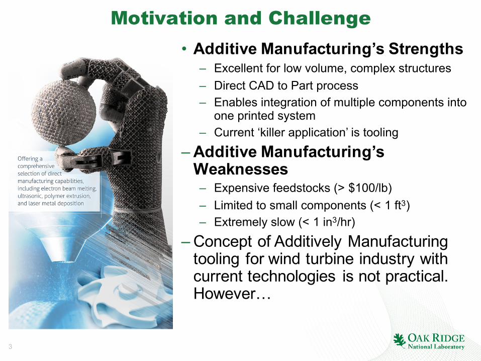
Motivation and Challenge• Additive Manufacturing’s Strengths
– Excellent for low volume, complex structures– Direct CAD to Part process– Enables integration of multiple components into
one printed system– Current ‘killer application’ is tooling
– Additive Manufacturing’s Weaknesses– Expensive feedstocks (> $100/lb)– Limited to small components (< 1 ft3)– Extremely slow (< 1 in3/hr)
– Concept of Additively Manufacturing tooling for wind turbine industry with current technologies is not practical. However…

4
Big Area Additive Manufacturing (BAAM)Big Area Additive Manufacturing• Targeting disruption in AM• Large (> 1000 cubic ft)• Fast (>2500 ci/hr)• Cheap (<$5/lb)• Low energy intensity (1 kW-hr/kg)• Composite materials (carbon fiber, glass fiber…)

5
Partnership withCRADA
ORNL and Cincinnati Incorporated collaborate to create commercial large-scale system
Partnership to establish US-based large-scale AM equipment manufacturer• Targets tooling lead time and cost reduction• Based on existing ORNL gantry system• Cincinnati providing >$1M in cost share year one
– First large-scale polymer AM system delivered to MDF, April 2014• Interest from multiple automotive, aerospace and tooling industries• Stretch form and hydroform tools demonstrated

6
High profile demonstrations
Local Motors Strati –first 3D printed car
(Sept 2014)
ORNL AMIE – scaling up printed car and house (Sept
2015)
Printed Cobra – first finished parts(Jan 2015)
Printed Jeep – Fast application coatings
(Nov 2015)
Printed Trim Tool –Guinness Largest
Printed Object(Aug. 2016)
Composite tooling with Boeing– (March 2016)
7
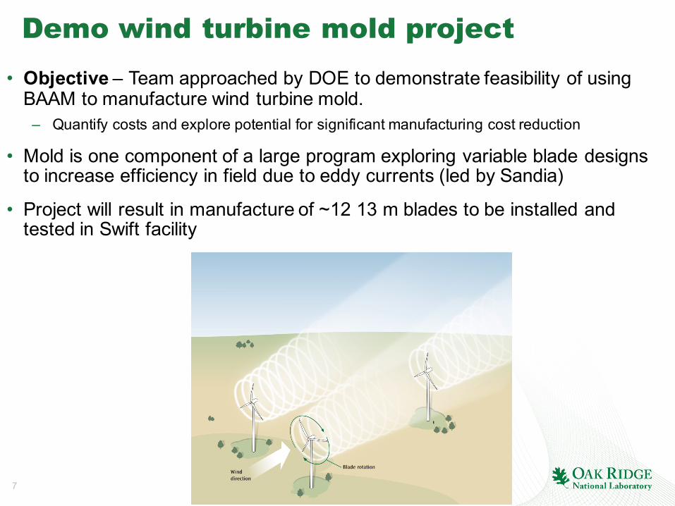
Demo wind turbine mold project• Objective – Team approached by DOE to demonstrate feasibility of using
BAAM to manufacture wind turbine mold. – Quantify costs and explore potential for significant manufacturing cost reduction
• Mold is one component of a large program exploring variable blade designs to increase efficiency in field due to eddy currents (led by Sandia)
• Project will result in manufacture of ~12 13 m blades to be installed and tested in Swift facility

8
Parameter Target (this project) Stretch (low volume) Production
Substrate bondinterface and coatings
Short beam shear test with no failure of interface at ambient
Short beam shear test with no failure of interface at 40 C
Short beam shear test with no failure of interface at 70 C
Mold temp (+/-5 C)
Ambient (need oven) 40 C (resin flows) 70 C (fast cure) with 100 C peak
Mold distortion Match HP to LP at ambient less than 1% of chord
Match HP to LP at 40 C less than 1% of chord
Match HP to LP at 70 C less than 1% of chord
Vacuum drop 30 mbar over 30 minutes
15 mbar over 60 minutes
15 mbar over 60 minutes
Assembly of mold pieces
Meet gap tolerance (defined next page) at Room temp
Meet gap tolerance at 40 C
Meet gap tolerance at 70 C
Life 4 blades 12 blades 1000 (production)
DemoWindMoldFabrication:DesignRequirements
9
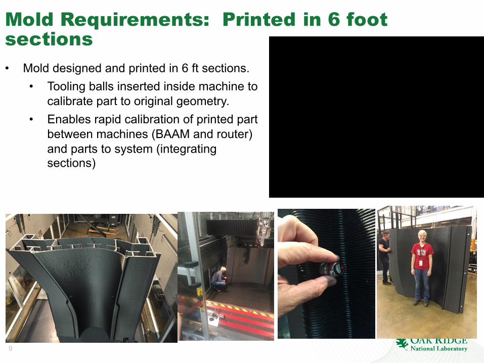
Mold Requirements: Printed in 6 foot sections• Mold designed and printed in 6 ft sections.
• Tooling balls inserted inside machine to calibrate part to original geometry.
• Enables rapid calibration of printed part between machines (BAAM and router) and parts to system (integrating sections)

10
Conventional layup
Mold Fabrication:Coatingsandsurfacefinish3D printed mold form with fiber glass layup machined down to mold line• ORNL/TPI design mold and use
Additive Manufacturing to make near net shape mold using CF/ABS. • Mold printed 4 mm below mold
surface.• TPI uses conventional layup of
fiberglass (8 mm). • ORNL machined 4 mm off to
get final mold surface.• Integrate ducted heating for final
mold
3D printed mold form
Conventional frame/scaffolding
Mold surface with 8mm of conventional layup/coating

11
Mold Fabrication: HeatingIntegral air heating
• Ducts designed into support structure for mold form• Eliminates embedded wiring and
electronics• One printed piece has structure,
ducting and interfaces to truss structure
• Integral commercial inline blowers/heaters complete the system• Flexible, reusable - blowers and
heaters can be transferred from mold to mold as opposed to embedded into each mold permanently
• Confident strategy applicable for full mold.

12
• Utilized14thermocouples(baselinemeasurements),thermalimagingandlaserscannertomeasuretemperatureandsurfacevariationsduringheating
• Experimentalvalidation• Thermocouple data
• Laserprofilometry data
• Thermalcyclingtrials
Experimental setup Laser tracker in foreground Thermal imaging on mold surface
MoldFabrication:Heatingtests
Surface temp Profile data
Results from all tests meet design requirements
13
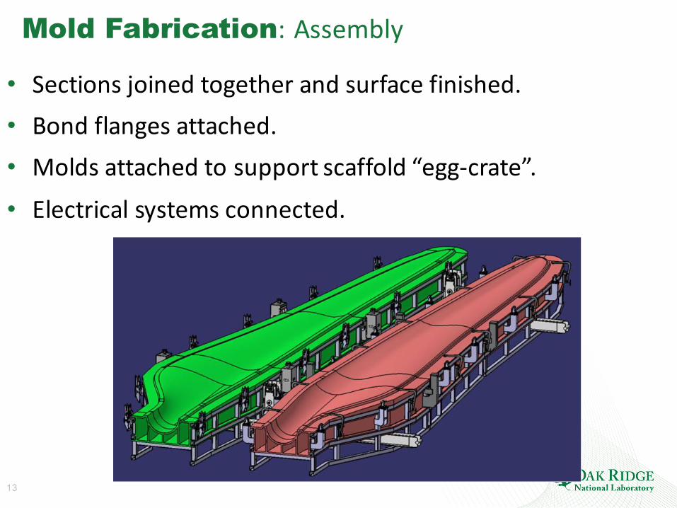
Mold Fabrication:Assembly
• Sectionsjoinedtogetherandsurfacefinished.• Bondflangesattached.• Moldsattachedtosupportscaffold“egg-crate”.• Electricalsystemsconnected.
14
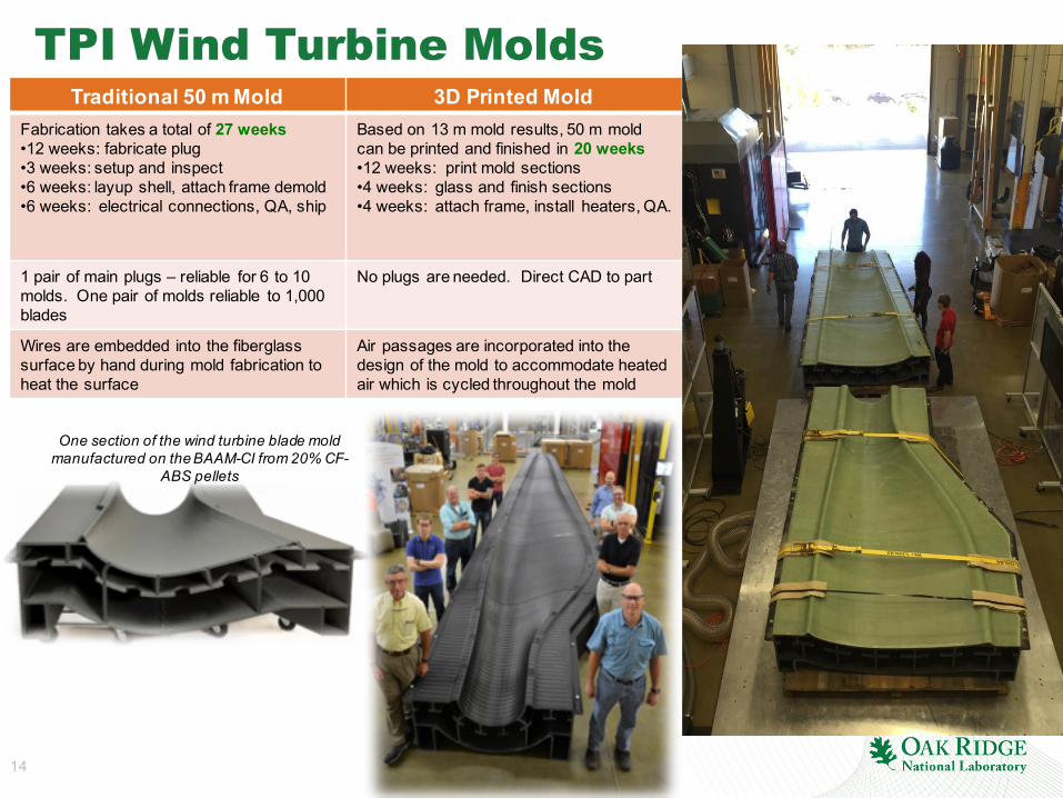
TPI Wind Turbine MoldsTraditional 50 m Mold 3D Printed Mold
Fabrication takes a total of 27 weeks•12 weeks: fabricate plug•3 weeks: setup and inspect•6 weeks: layup shell, attach frame demold•6 weeks: electrical connections, QA, ship
Based on 13 m mold results, 50 m mold can be printed and finished in 20 weeks•12 weeks: print mold sections•4 weeks: glass and finish sections•4 weeks: attach frame, install heaters, QA.
1 pair of main plugs – reliable for 6 to 10 molds. One pair of molds reliable to 1,000 blades
No plugs are needed. Direct CAD to part
Wires are embedded into the fiberglass surface by hand during mold fabrication to heat the surface
Air passages are incorporated into the design of the mold to accommodate heated air which is cycled throughout the mold
One section of the wind turbine blade mold manufactured on the BAAM-CI from 20% CF-
ABS pellets

15
SummaryofRiskReductionActivities
• Demonstratedprintedmoldsectionthatmet,orexceeded,targets• Temperaturevariationsexceedtargetof+/-5C(+/-3C)• Vacuumdropexceedstarget(2.6mbar, target15mbar)• Geometricvariationexceedtarget(0.1mmto0.2mm)
• Excellentadhesionbetweenfiberglasscoatingandprintedmaterial• Sixsuccessfultemperaturecycles• Useofstandardmaterial(fiberglass/epoxy) formold interface
• Printingenablesintegrationof• Ductedheating(reuseonmultiplemolds)• Designed flangesintostructureforeasyintegration intometaltruss(easeof
reuseandtransportation)
• Constructionofdemomoldsectionsandbladesectionwillprovideinsightshelpfulforfinalmolddesign,assembly,andbladeconstruction
16
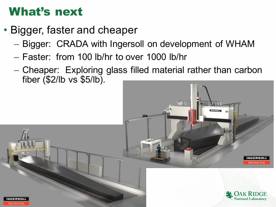
What’s next• Bigger, faster and cheaper
– Bigger: CRADA with Ingersoll on development of WHAM– Faster: from 100 lb/hr to over 1000 lb/hr– Cheaper: Exploring glass filled material rather than carbon
fiber ($2/lb vs $5/lb).