Additive Manufacturing With Next Generation Material ...
9
MSC Software: Engineering Lifecycle Management WHITEPAPER Additive Manufacturing With Next Generation Material Lifecycle Management System
Transcript of Additive Manufacturing With Next Generation Material ...
MSC Software: Engineering Lifecycle Management WHITEPAPER
Additive ManufacturingWith Next Generation
Material Lifecycle Management System
2
Additive Manufacturing With Next Generation Material Lifecycle Management SystemWHITEPAPER
MSC Software Corporation, the worldwide leader in Engineering Lifecycle Management,
would like to share some of our experiences and expertise in the application of Next
Generation Material Lifecycle Management (MLM) system.
THIS WHITE PAPER introduces Additive Manufacturing (AM) techniques, widely known as
21st century manufacturing, and its challenges. These processes related to material, machine
qualification, process characterization and application continue to be major consideration
factors in producing quality parts/assemblies. MSC Software’s advanced MLM system
known as MaterialCenter manages the workflow of additive manufacturing from customer
requirement to final delivery. It acts as a repository and maintains pedigree information of all
machine/process/build parameters through all stages of product lifecycle management. The
system develops predictive part behavior to quantify part performance (stiffness, strength
and life) and allows the usage of all stored data to guide emerging R&D and future method
development.
The paper is primarily intended for two type of readers:
ENGINEERING/MANUFACTURING MANAGERS who are involved in managing various
phases of design to production in additive manufacturing.
DESIGN/CAE/PROTOTYPE TEST & BUILD ENGINEERS who are involved in the day to day
product lifecycle activities (design/development/CAE/prototype build and test) and interested
in improving the end quality of AM parts/assemblies via application of an advanced material
lifecycle management system.
3
Additive Manufacturing With Next Generation Material Lifecycle Management System WHITEPAPER
INDEX
CONTACTS
1. EXECUTIVE SUMMARY 4
2. ADDITIVE MANUFACTURING PROCESS 4
3. WORKFLOW FROM DESIGN TO PRODUCTION
IN ADDITIVE MANUFACTURING 5
4. COMPARISON OF ADDITIVE AND SUBTRACTIVE MANUFACTURING 5
5. CONSIDERATION / MAJOR CHALLENGES IN AM 6
6. APPLICATION OF NEXT GENERATION MLM
SYSTEM IN ADDITIVE MANUFACTURING 6
7. MANAGEMENT OF AM WORKFLOW IN MSC’S MATERIAL CENTER 7
8. CONCLUSION 8
9. ABOUT MSC SOFTWARE 9
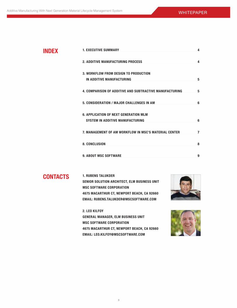
1. RUBENS TALUKDER
SENIOR SOLUTION ARCHITECT, ELM BUSINESS UNIT
MSC SOFTWARE CORPORATION
4675 MACARTHUR CT, NEWPORT BEACH, CA 92660
EMAIL: [email protected]
2. LEO KILFOY
GENERAL MANAGER, ELM BUSINESS UNIT
MSC SOFTWARE CORPORATION
4675 MACARTHUR CT, NEWPORT BEACH, CA 92660
EMAIL: [email protected]
4
Additive Manufacturing With Next Generation Material Lifecycle Management SystemWHITEPAPER
1. EXECUTIVE SUMMARYTraditional or conventional manufacturing methods have historically focused on the conversion of basic raw materials in various forms into finished product through subtractive processes. These techniques use well established design/fabrication methods, tools, equipment (e.g. foundry, lathe, CNC, etc), production activities and steps.
44
Additive Manufacturing (AM) is a monumental shift from conventional
manufacturing methods. Widely known as 3D printing, AM is modern
manufacturing. Fig. 1. and Fig. 2. present both types of manufacturing
processes.
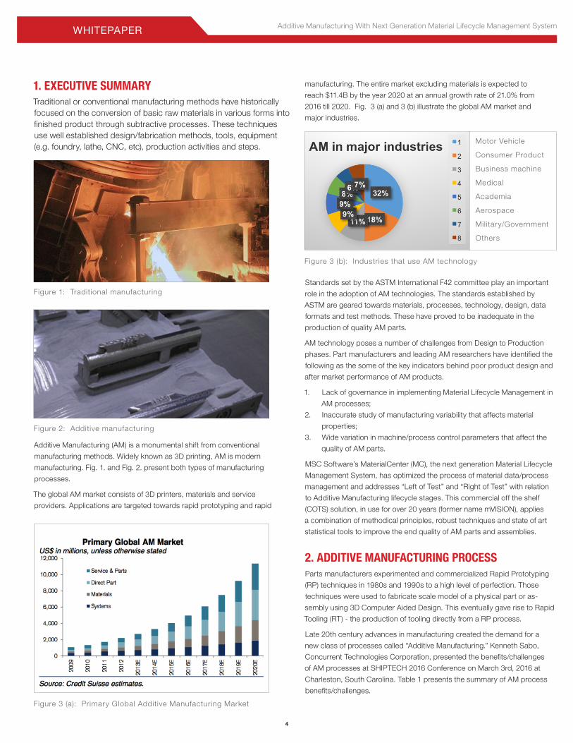
The global AM market consists of 3D printers, materials and service
providers. Applications are targeted towards rapid prototyping and rapid
Figure 1: Traditional manufacturing
Figure 2: Additive manufacturing
Figure 3 (a): Primary Global Additive Manufacturing Market
Figure 3 (b): Industries that use AM technology
manufacturing. The entire market excluding materials is expected to
reach $11.4B by the year 2020 at an annual growth rate of 21.0% from
2016 till 2020. Fig. 3 (a) and 3 (b) illustrate the global AM market and
major industries.
Motor Vehicle
Consumer Product
Business machine
Medical
Academia
Aerospace
Military/Government
Others
Standards set by the ASTM International F42 committee play an important
role in the adoption of AM technologies. The standards established by
ASTM are geared towards materials, processes, technology, design, data
formats and test methods. These have proved to be inadequate in the
production of quality AM parts.
AM technology poses a number of challenges from Design to Production
phases. Part manufacturers and leading AM researchers have identified the
following as the some of the key indicators behind poor product design and
after market performance of AM products.
1. Lack of governance in implementing Material Lifecycle Management in
AM processes;
2. Inaccurate study of manufacturing variability that affects material
properties;
3. Wide variation in machine/process control parameters that affect the
quality of AM parts.
MSC Software’s MaterialCenter (MC), the next generation Material Lifecycle
Management System, has optimized the process of material data/process
management and addresses “Left of Test” and “Right of Test” with relation
to Additive Manufacturing lifecycle stages. This commercial off the shelf
(COTS) solution, in use for over 20 years (former name mVISION), applies
a combination of methodical principles, robust techniques and state of art
statistical tools to improve the end quality of AM parts and assemblies.
2. ADDITIVE MANUFACTURING PROCESSParts manufacturers experimented and commercialized Rapid Prototyping
(RP) techniques in 1980s and 1990s to a high level of perfection. Those
techniques were used to fabricate scale model of a physical part or as-
sembly using 3D Computer Aided Design. This eventually gave rise to Rapid
Tooling (RT) - the production of tooling directly from a RP process.
Late 20th century advances in manufacturing created the demand for a
new class of processes called “Additive Manufacturing.” Kenneth Sabo,
Concurrent Technologies Corporation, presented the benefits/challenges
of AM processes at SHIPTECH 2016 Conference on March 3rd, 2016 at
Charleston, South Carolina. Table 1 presents the summary of AM process
benefits/challenges.
5
Additive Manufacturing With Next Generation Material Lifecycle Management System WHITEPAPER
Common application of Additive Manufacturing may be found in the
following products. Fig. 4 exhibits a sample part produced via Additive
Manufacturing.
• Medical Implants;
• Mold/Die manufacturing;
• Weight Reduction through topology optimization;
• Brackets/Tools/Fixtures;
• Patterns;
• Custom fit assemblies;
• Small production runs.
Table 1: AM process benefits/challenges
Figure 4: Fuel Nozzle of GE Leap Engine
Figure 6: MakerBot replicator 2 AM Machine, Figure 7: Typical AM Build Tray & Printhead
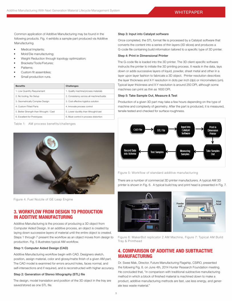
Figure 5: Workflow of standard additive manufacturing
Benefits Challenges
1. Low Quantity Requirement 1. Qualify machine/process materials
2. No tooling, No Setup 2. Consistency across all machine/builds
3. Geometrically Complex Design 3. Cost effective logistics solution
4. Custom Fitted Parts 4. Innovate process control
5. Better Strength than Wrought / Cast 5. Lower ductility than Wrought/cast
6. Excellent for Prototypes 6. Must control in process distortion
3. WORKFLOW FROM DESIGN TO PRODUCTION IN ADDITIVE MANUFACTURINGAdditive Manufacturing is the process of producing a 3D object from
Computer Aided Design. In an additive process, an object is created by laying down successive layers of material until the entire object is created.
Steps 1 through 7 present the workflow as an object moves from design to
production. Fig. 5 illustrates typical AM workflow.
Step 1: Computer Aided Design (CAD)
Additive Manufacturing workflow begin with CAD. Designers sketch,
position, assign material, color and glossy/matte finish of a given AM part.
The CAD model is examined for errors around holes, faces normal, and
self-intersections and if required, and is reconstructed with higher accuracy.
Step 2: Generation of Stereo lithography (STL) file
The design, model translation and position of the 3D object in the tray are
saved/stored as one STL file.
Step 3: Input into Catalyst software
Once completed, the STL format file is processed by a Catalyst software that
converts the content into a series of thin layers (3D slices) and produces a
G-code file containing build information tailored to a specific type of 3D printer.
Step 4: Print in Dimensional Printer
The G-code file is loaded into the 3D printer. The 3D client specific software
instructs the printer to initiate the 3D printing process. It reads in the data, lays
down or adds successive layers of liquid, powder, sheet metal and other in a
layer upon layer fashion to fabricate a 3D object. Printer resolution describes
the layer thickness and X-Y resolution in dots per inch (dpi) or micrometers (um).
Typical layer thickness and X-Y resolution is around 250 DPI, although some
machines can print as thin as 1600 DPI.
Step 5: Take Sample Out, Measure & Test
Production of a given 3D part may take a few hours depending on the type of
machine and complexity of geometry. After the part is produced, it is measured,
tensile tested and checked for surface roughness.
There are a number of commercial 3D printer manufacturers. A typical AM 3D
printer is shown in Fig. 6. A typical build tray and print head is presented in Fig. 7.
4. COMPARISON OF ADDITIVE AND SUBTRACTIVE MANUFACTURINGDr. Swee Mak, Director, Future Manufacturing Flagship, CSIRO, presented
the following Fig. 8. on June 4th, 2014 Hunter Research Foundation meeting.
He concluded that, “in comparison with traditional subtractive manufacturing
method in which a block of finished material is machined down to make a
product, additive manufacturing methods are fast, use less energy, and gener-
ate less waste material.”
6
Additive Manufacturing With Next Generation Material Lifecycle Management SystemWHITEPAPER
will lead to reduced machine downtime – currently a major issue for
many machines and processes.
• Machine qualification: Machine to machine as well as part to part
repeatability is noted to be high. Part placement consideration (part
placement, location and build angles based on machine capabilities)
needs to be fine-tuned. Material strength relative to build axis/orienta-
tion needs to be estimated via statistical analysis. A series of “what If”
studies is required to understand the high level of variance.
Most of the mid/large sized US manufacturers deal with the above chal-
lenges on a day to day basis. Some of the concerns expressed by them are
as follows:
1. Is additive manufacturing producing lightweight, cost-effective, quality products?
2. Does additive manufacturing make sense?
3. What should I recommend to logistics/suppliers?
4. What is the sensitivity matrix of key variables?
5. Why is the surface finish too rough or too fine?
6. Why is powder scrap rate so high?
6. APPLICATION OF NEXT GENERATION MLM SYSTEM IN ADDITIVE MANUFACTURINGMaterials Lifecycle Management (MLM), a subset of Product Lifecycle
Management (PLM), provides linkages between items and attributes about
information items as well as the information items themselves of “Left of
Test,” Actual Test Cycle and “Right of Test.” Thus, it directly addresses the
issue of the traceability of data in complex environment. This is because
the system stores the pedigree of the information creation process for each
process step. The data, stored as an information structure, is interpretable
both by people and by computers, defining the exact context of each item
of information. Fig. 10 illustrates the lifecycle stages of MLM.
Traditional MLM systems cannot address the challenges posed by AM
processes. Next generation MLM systems are architected/developed/
implemented specifically to solve AM issues from design to production
stages.
Advanced MLM systems integrate Additive Manufacturing to Physical/
Virtual tests to CAE, PLM/PDM. Some of the capabilities are listed below.
Figure 8: Comparison of Additive and Subtractive manufacturing
Figure 10: Materials Lifecycle Management
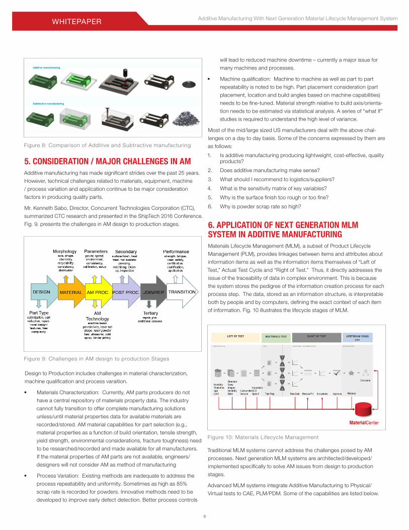
Figure 9: Challenges in AM design to production Stages
5. CONSIDERATION / MAJOR CHALLENGES IN AMAdditive manufacturing has made significant strides over the past 25 years.
However, technical challenges related to materials, equipment, machine
/ process variation and application continue to be major consideration
factors in producing quality parts.
Mr. Kenneth Sabo, Director, Concurrent Technologies Corporation (CTC),
summarized CTC research and presented in the ShipTech 2016 Conference.
Fig. 9. presents the challenges in AM design to production stages.
Design to Production includes challenges in material characterization,
machine qualification and process varaition.
• Materials Characterization: Currently, AM parts producers do not
have a central repository of materials property data. The industry
cannot fully transition to offer complete manufacturing solutions
unless/until material properties data for available materials are
recorded/stored. AM material capabilities for part selection (e.g.,
material properties as a function of build orientation, tensile strength,
yield strength, environmental considerations, fracture toughness) need
to be researched/recorded and made available for all manufacturers.
If the material properties of AM parts are not available, engineers/
designers will not consider AM as method of manufacturing
• Process Variation: Existing methods are inadequate to address the
process repeatability and uniformity. Sometimes as high as 85%
scrap rate is recorded for powders. Innovative methods need to be
developed to improve early defect detection. Better process controls
7
Additive Manufacturing With Next Generation Material Lifecycle Management System WHITEPAPER
7
Figure 11: Ecosystem and Integration touchpoints of Next Generation MLM system
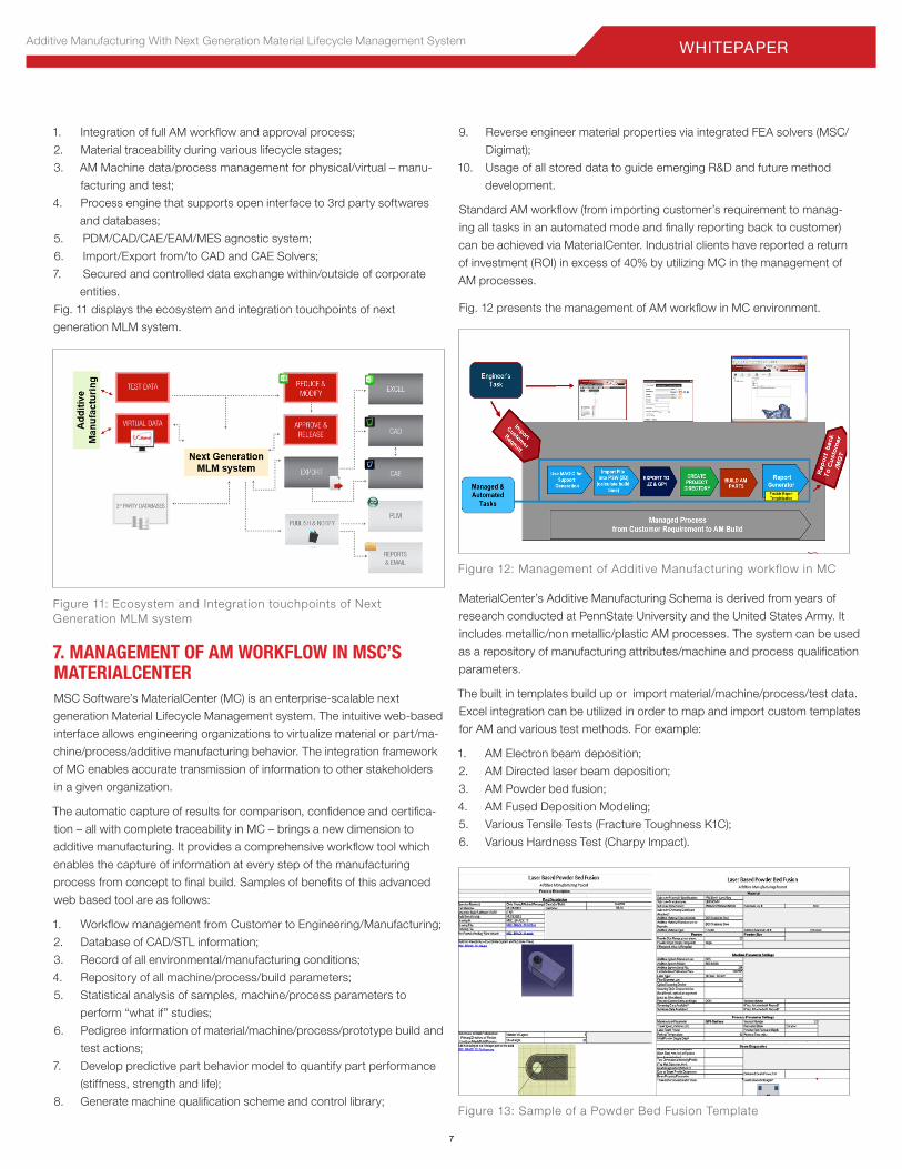
Figure 13: Sample of a Powder Bed Fusion Template
Figure 12: Management of Additive Manufacturing workflow in MC
1. Integration of full AM workflow and approval process;
2. Material traceability during various lifecycle stages;
3. AM Machine data/process management for physical/virtual – manu-
facturing and test;
4. Process engine that supports open interface to 3rd party softwares
and databases;
5. PDM/CAD/CAE/EAM/MES agnostic system;
6. Import/Export from/to CAD and CAE Solvers;
7. Secured and controlled data exchange within/outside of corporate
entities.
Fig. 11 displays the ecosystem and integration touchpoints of next
generation MLM system.
7. MANAGEMENT OF AM WORKFLOW IN MSC’S MATERIALCENTERMSC Software’s MaterialCenter (MC) is an enterprise-scalable next
generation Material Lifecycle Management system. The intuitive web-based
interface allows engineering organizations to virtualize material or part/ma-
chine/process/additive manufacturing behavior. The integration framework
of MC enables accurate transmission of information to other stakeholders
in a given organization.
The automatic capture of results for comparison, confidence and certifica-
tion – all with complete traceability in MC – brings a new dimension to
additive manufacturing. It provides a comprehensive workflow tool which
enables the capture of information at every step of the manufacturing
process from concept to final build. Samples of benefits of this advanced
web based tool are as follows:
1. Workflow management from Customer to Engineering/Manufacturing;
2. Database of CAD/STL information;
3. Record of all environmental/manufacturing conditions;
4. Repository of all machine/process/build parameters;
5. Statistical analysis of samples, machine/process parameters to
perform “what if” studies;
6. Pedigree information of material/machine/process/prototype build and
test actions;
7. Develop predictive part behavior model to quantify part performance
(stiffness, strength and life);
8. Generate machine qualification scheme and control library;
9. Reverse engineer material properties via integrated FEA solvers (MSC/
Digimat);
10. Usage of all stored data to guide emerging R&D and future method
development.
Standard AM workflow (from importing customer’s requirement to manag-
ing all tasks in an automated mode and finally reporting back to customer)
can be achieved via MaterialCenter. Industrial clients have reported a return
of investment (ROI) in excess of 40% by utilizing MC in the management of
AM processes.
Fig. 12 presents the management of AM workflow in MC environment.
MaterialCenter’s Additive Manufacturing Schema is derived from years of
research conducted at PennState University and the United States Army. It
includes metallic/non metallic/plastic AM processes. The system can be used
as a repository of manufacturing attributes/machine and process qualification
parameters.
The built in templates build up or import material/machine/process/test data.
Excel integration can be utilized in order to map and import custom templates
for AM and various test methods. For example:
1. AM Electron beam deposition;
2. AM Directed laser beam deposition;
3. AM Powder bed fusion;
4. AM Fused Deposition Modeling;
5. Various Tensile Tests (Fracture Toughness K1C);
6. Various Hardness Test (Charpy Impact).
8
Additive Manufacturing With Next Generation Material Lifecycle Management SystemWHITEPAPER
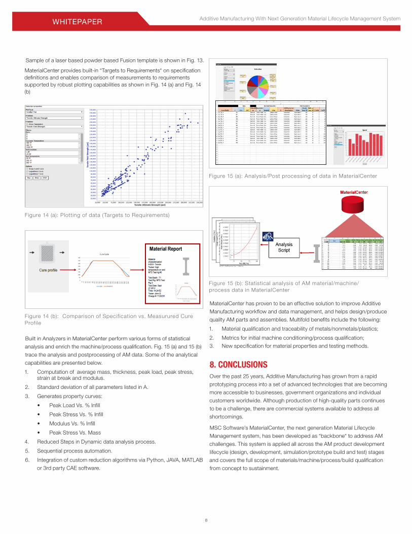
Sample of a laser based powder based Fusion template is shown in Fig. 13.
MaterialCenter provides built-in “Targets to Requirements“ on specification definitions and enables comparison of measurements to requirements supported by robust plotting capabilities as shown in Fig. 14 (a) and Fig. 14 (b)
MaterialCenter has proven to be an effective solution to improve Additive
Manufacturing workflow and data management, and helps design/produce
quality AM parts and assemblies. Multifold benefits include the following:
1. Material qualification and traceability of metals/nonmetals/plastics;
2. Metrics for initial machine conditioning/process qualification;
3. New specification for material properties and testing methods.
8. CONCLUSIONSOver the past 25 years, Additive Manufacturing has grown from a rapid
prototyping process into a set of advanced technologies that are becoming
more accessible to businesses, government organizations and individual
customers worldwide. Although production of high-quality parts continues
to be a challenge, there are commercial systems available to address all
shortcomings.
MSC Software’s MaterialCenter, the next generation Material Lifecycle
Management system, has been developed as “backbone“ to address AM
challenges. This system is applied all across the AM product development
lifecycle (design, development, simulation/prototype build and test) stages
and covers the full scope of materials/machine/process/build qualification
from concept to sustainment.
Figure 14 (a): Plotting of data (Targets to Requirements)
Figure 14 (b): Comparison of Specif ication vs. Measurured Cure Profile
Figure 15 (a): Analysis/Post processing of data in MaterialCenter
Figure 15 (b): Statistical analysis of AM material/machine/process data in MaterialCenter
Built in Analyzers in MaterialCenter perform various forms of statistical
analysis and enrich the machine/process qualification. Fig. 15 (a) and 15 (b)
trace the analysis and postprocessing of AM data. Some of the analytical
capabilities are presented below.
1. Computation of average mass, thickness, peak load, peak stress, strain at break and modulus.
2. Standard deviation of all parameters listed in A.
3. Generates property curves:
• Peak Load Vs. % Infill
• Peak Stress Vs. % Infill
• Modulus Vs. % Infill
• Peak Stress Vs. Mass
4. Reduced Steps in Dynamic data analysis process.
5. Sequential process automation.
6. Integration of custom reduction algorithms via Python, JAVA, MATLAB
or 3rd party CAE software.
9
Additive Manufacturing With Next Generation Material Lifecycle Management System WHITEPAPER
The MSC Software corporate logo, MSC, and the names of the MSC Software products and services referenced herein are trademarks or registered trademarks of the MSC Software Corporation in the United States and/or other countries. All other trademarks belong to their respective owners. © 2016 MSC Software Corporation. All rights reserved.
Asia-PacificMSC Software (S) Pte. Ltd. 100 Beach Road#16-05 Shaw Towers Singapore 189702Telephone 65.6272.0082
JapanMSC Software LTD. Shinjuku First West 8F23-7 Nishi Shinjuku1-Chome, Shinjuku-KuTokyo, Japan 160-0023Telephone 81.3.6911.1200
Europe, Middle East, AfricaMSC Software GmbHAm Moosfeld 1381829 Munich, GermanyTelephone 49.89.21093224 Ext.495
CorporateMSC Software Corporation4675 MacArthur CourtSuite 900Newport Beach, CA 92660Telephone 714.540.8900www.mscsoftware.com
WP-AM+MLM*2016MAY*WP
ABOUT MSC SOFTWAREMSC Software is the global leader in multidiscipline simulation solutions that help
companies improve quality, save time, and reduce costs associated with designing
and testing manufactured products. MSC Software works with thousands of
companies worldwide to develop better products faster with engineering simulation
technology, software, and services. For additional information about MSC
Software’s products and services, please visit www.mscsoftware.com.
MSC Software’s products and services are used by 900 of the top 1000
manufacturers in the world, across several industries including aerospace, defense,
automotive, transportation, agricultural equipment, heavy machinery, medical
devices, oil and gas, nuclear, consumer products, renewable energy, packaging,
electronics, and shipbuilding.