
Additive manufacturing as a mean of rapid prototyping ...
67
Saimaa University of Applied Sciences Faculty of Technology, Lappeenranta Degree Programme in Mechanical Engineering and Production Technology Anastasia Levchenko Additive manufacturing as a mean of rapid prototyping: from words to the actual model Case company: Drive! Team Thesis 2015
Transcript of Additive manufacturing as a mean of rapid prototyping ...

Saimaa University of Applied Sciences Faculty of Technology, Lappeenranta Degree Programme in Mechanical Engineering and Production Technology Anastasia Levchenko
Additive manufacturing as a mean of rapid prototyping: from words to the actual model
Case company: Drive! Team Thesis 2015

2
Abstract
Anastasia Levchenko Additive manufacturing as a mean of rapid prototyping: from words to the actual model, XX pages, XX appendices Saimaa University of Applied Sciences Faculty of Technology Lappeenranta Degree Programme in Mechanical Engineering and Production Technology Thesis 2015 Instructor: Senior Lecturer Simo Sinkko, Saimaa University of Applied Sciences
The purpose of the study was to get a deeper knowledge of additive manufacturing, its techniques, benefits, trends and challenges, and to create a better commercial prototype of a gearbox and give clear guidelines how to turn a design into reality with the help of 3D technologies.
The data for this thesis were gathered from the secondary sources, particularly articles and books. The information included core concepts of additive manufacturing, prototyping and design. Empirical findings were collected through the process of model evaluation provided by the case company and 3D design.
The result of the study can be seen in a new prototype design required by the case company. By examining the empirical findings, it was found out what kind of characteristics should be found in the proper commercial prototype, what were pros and cons of the previous versions, and what is the best way to design and manufacture the better prototype. Based on the findings, clear guidelines were given to the case company how to utilize the results of the model evaluation and design made by the author. Further research could investigate how the printed version of the model could work.
Keywords: additive manufacturing, gearbox, 3D printing, Drive!

3
Table of Contents
Table of Contents .............................................................................................. 3
List of abbreviations ......................................................................................... 4
1 Introduction .................................................................................................. 5
1.1 Background of the study ......................................................................... 5
1.2 Project .................................................................................................... 6
1.3 Objectives .............................................................................................. 7
1.4 Delimitations ........................................................................................... 7
1.5 Practical method..................................................................................... 8
1.6 Structure of the study ............................................................................. 9
2 Additive manufacturing .............................................................................. 10
2.1 What is additive manufacturing? .......................................................... 10
2.2 Methods and techniques of 3D printing ................................................ 10
2.2.1 Selective Laser Sintering (SLS) ................................................... 11
2.2.2 Stereolithography Apparatus (SLA) ............................................. 12
2.2.3 Fused Deposit Modeling (FDM) ................................................... 13
2.3 Benefits of additive manufacturing ....................................................... 15
2.4 Limitations and challenges ................................................................... 18
2.4.1 Demerits of additive manufacturing ............................................. 19
2.4.2 What is still holding AM back? ..................................................... 20
2.5 Future of additive manufacturing .......................................................... 22
2.5.1 Forecasts and predictions ........................................................... 22
2.5.2 Possibilities for the near future .................................................... 26
3 Prototyping................................................................................................. 31
3.1 Prototyping – WHAT and WHY? .......................................................... 31
3.2 Types ................................................................................................... 31
3.3 Rapid prototyping ................................................................................. 34
3.4 RP vs. AM: is there any difference? ..................................................... 35
4 Model evaluation ........................................................................................ 35
4.1 General information .............................................................................. 36
4.2 Pros and cons of the model .................................................................. 37
4.2.1 3D model ..................................................................................... 37
4.2.2 Current prototypes ....................................................................... 39
4.3 Ideas for improvement .......................................................................... 42
5 Design ....................................................................................................... 43
5.1.1 Sketch ......................................................................................... 43
5.1.2 Modeling ...................................................................................... 45
5.2 Assembly .............................................................................................. 57
6 Conclusion ................................................................................................. 59
6.1 Summary and discussions ................................................................... 59
6.2 Recommendations for further research ................................................ 61
Figures .............................................................................................................. 62
Tables ............................................................................................................... 62
References........................................................................................................ 63

4
List of abbreviations
A&D aerospace and defense p. 30 AM additive manufacturing p. 10 ABS acrylonitrile butadiene styrene p. 14 CAD computer-aided design p. 10 CAGR compound annual growth rate p. 23 CNC computer numerical control p. 28 EFV expeditionary fighting vehicle p. 34 EPSRC Engineering and Physical Sciences Research Council p. 16 FDM fused deposit modeling p. 13 HDPE high-density polyethylene p. 14 HuGOR Hub Gear Off-Road p. 6 LUT Lappeenranta University of Technology p. 6 SLA stereolithography apparatus p. 12 SLS selective laser sintering p. 11 STL Standard Tessellation Language p. 12 PLA polylactic acid p. 14 PMSM permanent magnet synchronous motor p. 6 RP rapid prototyping p. 34 RTV room temperature vulcanization p. 14 UV ultraviolet p. 13

5
Introduction
Background of the study
As a part of industry and technology, three-dimensional printing, or additive
manufacturing, has been around for already more than thirty years as a rapid
prototyping technology - fast and cost-effective method for creating prototypes
for product development within industry (3D Printing Industry, 2015). Although it
has been available for years, it is only recently that 3D printing technology has
found its way on the markets, which helped it to become another mainstream of
the century. Since then, the technology is now used in prototyping and
distributed manufacturing with applications from architecture to fashion, from
aerospace to dental technology, and way beyond.
Almost every year the world is introducing more and more innovations in the
field of 3D printing. Louis Columbus (2014) deems that the recent exponential
development and enthusiasm around 3D printing made the market one of the
most promising markets for the years to come (see Table 1.1).
Table 1.1 Global 3D Printing Market (Forbes 2014)
The forecast presented above can also be explained by the facts pictured below
(see Figure 1.1). Indeed, the commodity prices are decreasing, resulting of
much cheaper prices for 3D printers, which allow a significantly higher demand.

6
On the other hand, the evolution of the technology is giving the opportunity to
produce at a much faster pace a much bigger amount of products.
Figure 1.1 Additive Manufacturing Forecast (Siemens AG 2015)
Moreover, according to David Green (2014) and his article published in The
Conversation Trust online journal, 3D printing has pushed the boundaries
allowing the technology to expand its capabilities and applications. This step
has made 3D one of the top tech innovations of 2014.
All of the facts mentioned above and even more have aroused interest of the
author to explore the world of additive manufacturing and rapid prototyping and
find the way to exploit its techniques for the application purposes of the project.
Project
Drive! Team is a cooperation of Saimaa University of Applied Sciences and
Lappeenranta University of Technology (LUT) graduates (engineers, Bachelor
and Master alumni‘s, Doctors from LUT). They are aimed at creating a new type
of electric traction motor system that fulfills the special needs of the off-road
vehicles.
A new concept that integrates a permanent magnet synchronous motor (PMSM)
and a two-step planetary gearbox for heavy machinery electric traction was
introduced by the Drive! Team in 2012 with the ―HuGOR‖ (Hub Gear Off-Road,
2012-2014) project. The team has found out that there is a need for this kind of
solution in the field of diesel-electric hybrid off-road vehicles, where electrical
machines simply cannot fulfill all the demands of the typical load cycles of

7
working machines on their own. They developed a mechanical gearbox for
electric motors, which prototype was manufactured and tested.
The project team is currently working on two projects simultaneously: In-
HuGOR (2013-2015) and Drive! (2014-2016). In a nutshell, In-HuGOR is an
innovative solution for the fully integrated structure of a gearbox and electric
motor. By now, the project team has already completed several phases
(electrical and mechanical engineering, prototype manufacturing) of the In-
HuGOR project and now they are waiting for the prototype to be tested.
Drive! is more centered around the commercialization of the project. The team
has set a long-term goal in appearing on the market as a new company but, at
first, the commercial potential of the integrated solution has to be discovered.
There is a need in contacting potential customers to receive the feedback,
which will help the project team to understand the pros and cons of the solution
they came up with.
Objectives
The first objective of the following study is to give a portrayal of additive
manufacturing and prototyping, their concepts, techniques, recent trends and
challenges for the future.
Another objective is to design and manufacture a better prototype of the
gearbox by applying the knowledge gained through the theoretical studies. The
author aims at presenting a functional and good-looking model so that it can be
used later in project commercialization and customer contacts.
But before designing a new prototype, the author has to evaluate the previous
prototype of the gearbox, assess its pros and cons in order to determine how to
improve it and/or use it to build a more satisfying prototype for the project team.
Delimitations
Additive manufacturing is a very broad concept involving many objects and
topics that can be explored. However, as the study is based on a specific
project, the delimitations will narrow the study to the inner objectives of the
project.

8
First of all, at the moment of conducting the present study, the project team has
already delivered the results regarding technical goals of the project. Moreover,
it has been said that the main goal is to receive an object suitable for
commercialization. For the author there is no need to intensely study any
theoretical information about the motors for the heavy machinery.
Secondly, the project team is interested in receiving a good-looking and efficient
prototype suitable for commercial purposes. The concept of the planetary
gearbox has been introduced and approved, so it cannot be changed
completely. The main idea is to come up with a simple solution that will give
people an easy way to understand the key features of the model without digging
too deep and also to make it attractive for promotional purposes. It should also
help to make the printing process easier.
Thirdly, the result should be achieved through the process of additive
manufacturing that includes all the steps from the 3D design to the actual 3D
printing that has already been used before for the creation of the previous
prototype. The 3D printer that is available for the author in the Saimaa
University of Applied Sciences is using the particular technology called fused
deposition modeling (FDM). This means that no other method of additive
manufacturing can be used in order to achieve the result.
Practical method
One of the aims of this study is to create a real 3D prototype that will clearly
represent the main working principles of the gearbox and be a good-looking
example of the real machine element. In order to design and produce the model
that will fulfill the needs of the project and come up with the proper result in the
end, 3D modeling and printing methods will be used.
3D modeling is a process of creating a 3D model via specific software. For the
prototyping, using 2D models is not really efficient because it is not only time
consuming, but it is also impossible to show the complexity of the model and to
show the features that need attention.
The software that is used by the author for the purpose of the study is
SolidWorks. It is the most common computer-aided design software used in

9
Saimaa University of Applied Sciences and Lappeenranta University of
Technology.
3D printing is the next step on the way to achieve the goal of the study. It is a
technology that applies one of the several processes to make a 3D object
based on the previously done 3D model. It is a fast and effective way of creating
a prototype.
It was already mentioned that the equipment used in the empirical part is based
on the fused deposit modeling technology that is described in Chapter 2 of this
work. The author will go through the theory and principles of 3D printing
technologies more deeply further in the work.
In general, the combination of 3D modeling and printing generates a detailed,
efficient and clean-cut prototype, and this can really contribute to in-depth
understanding of the concept brought up by the project team and helping the
commercialization of the project.
Structure of the study
The current study consists of two main parts: theoretical and empirical. The first
section reviews theoretical information regarding additive manufacturing and
related processes found in books, magazines and various Internet sources. It
explains theoretical concepts and highlights important aspects and follows
trends on the field of additive manufacturing.
The second part of the study includes the empirical implementation which
consists of both, design and manufacturing that will apply theoretical knowledge
to practice, follow the guidelines of the project and appear as an efficient
solution for acquiring sponsors and customers for the project idea.
In the end, the summary highlights discussions and make relevant conclusions
of the study.

10
Additive manufacturing
What is additive manufacturing?
It is hard to find an attractive explanation to shortly describe the meaning of the
additive manufacturing. Roland Berger (2014) deems that additive
manufacturing (AM) is an additive process of making a three-dimensional solid
object of virtually any shape from a digital model, where materials are applied in
successive layers under computer control. It is also distinguished from
traditional subtractive machining techniques that rely on the removal of the
material by methods such as cutting or milling.
Generally speaking, additive manufacturing, which is the appropriate name for
3D printing, is a set of technologies that build 3D objects by adding layer-upon-
layer of material. In cooperation with computer-aided design (CAD) software,
this technique allows the creation of new types of object with exclusive material
properties. Nowadays, the range of materials expanded way further than plastic
or metal. Concrete, polymers, paper, food substances, bio materials are about
to become more and more popular and common, following the application
purposes and innovation trends.
The term Additive Manufacturing also includes a wide range of technologies,
from laser sintering to fused deposit modeling and stereolithography and many
more. These technologies have been used in various industries like automotive,
consumer electronics or even more recently for medical applications
(prosthetics, aligners, skull segments, etc.).
Methods and techniques of 3D printing
A diverse spectrum of methods and technologies are sheltered under the
umbrella of additive manufacturing. There is a large number of different 3D
printing technologies with varying assets and advantages, limitations and
perspectives, and all of them are universally available. Some are excellent for
rapid prototyping during the development process, whereas others are suited
for rapid manufacturing of production-ready parts.

11
And yet, from the authors‘ point of view, it is possible to highlight three popular
printing technologies that are used more often in modern 3D
printing: SLS, FDM and SLA.
Selective Laser Sintering (SLS)
Sintering itself is a process of creating objects from powders using atomic
diffusion — to create a three dimensional object. This technology has been
used for thousands of years to create everyday objects like bricks, porcelain
and jewelry (Palermo 2013).
Laser sintering is a laser based 3D printing process that works with powdered
materials. The SLS process was developed and patented in the 1980s by Carl
Deckard — back then an undergraduate student at the University of Texas —
and his mechanical engineering professor, Joe Beaman (Palermo 2013).
The laser is traced across a powder bed of a tightly compacted powdered
material, according to the 3D data downloaded to the machine in the XY-axes.
As the laser interacts with the surface of the material, it sinters the particles to
each other to form a solid. During the building cycle, the platform, on which the
building is repositioned, lowered by a single layer thickness (see Figure 2.1).
The process repeats until the model is completed. Once finished, the entire
powder bed is removed from the machine and the excess powder can be
removed to leave the ‘printed‘ parts. When the object is fully formed, it is left to
cool down in the machine before being removed.
Figure 2.1 Laser Sintering Process (3D Industry 2015)

12
Materials:
polymers: nylon (neat, glass-filled, etc.) or polystyrene;
plastic;
metals: steel, titanium, alloy mixtures (all require much higher powdered laser and higher in-process temperatures);
ceramics;
green sand.
Benefits of SLS
Compared to other AM processes, SLS can:
easily make very complex geometries directly from digital CAD data;
construct complex geometries without any support structures due to the fact that the part being constructed is surrounded by unsintered powder at all times;
produce much stronger parts (compared to stereolithography, for example).
Stereolithography Apparatus (SLA)
Stereolithography is a laser-based process which employs a vessel of liquid
ultraviolet curable photopolymer (resin) that reacts with the UV-laser and cure to
form very precise and accurate solid parts. Simply said, a process by which a
uniquely designed 3D printing machine, called a stereolithography apparatus
(SLA) converts liquid plastic into solid objects (Palermo 2013).
As well as in SLS, a computer aided design (CAD) file has to be adapted for the
3D printing machine to recognize it. For this purpose, Chuck Hull, co-founder of
3D Systems, Inc., a leader in the 3D printing industry, created a Standard
Tessellation Language (STL) - a file type that is most commonly used for
stereolithography, as well as other additive manufacturing processes since the
late 1980‘s. Generally speaking, this STL file is ‖cutting up‖ CAD models in
layers, so it gives a 3D machine the information it needs to print out every single
layer.
After patented in 1986, stereolithography was recognized as one of the first 3D
processes, and still today, it is one of the widely used techniques, if not the
most, in rapid prototyping for plastic models.
The building process occurs in a pool of resin. A laser beam, directed into the
pool, traces the cross-section pattern of the model according to the 3D data

13
supplied to the machine (the .STL file) for a particular layer and cures it. The
ultraviolet-curable liquid hardens instantly when the ultraviolet (UV) laser
touches it. During the production cycle, the platform, on which the future model
is repositioned, is lowering by a single layer thickness (see Figure 2.2). This
process is repeated all over again until the entire object is formed and fully
submerged in the tank. The platform is then raised to expose a three-
dimensional object. Finally, the object is baked in an ultraviolet oven to further
cure the plastic.
Figure 2.2 Stereolithography Process (3D Industry 2015)
Benefits of SLA
It was already mentioned that SLA is claimed to be one of the most popular and
widely used technologies in the field of 3D printing. The author has figured out
possible aspects that make this process attractive and beneficial:
relatively low cost for low-volume production compared to other 3D printing methods;
SLA is one of the most accurate 3D printing techniques with excellent surface finish;
manufacturing speed varies from a few hours to more than a day, depending on the product size and complexity.
Fused Deposit Modeling (FDM)
Another commonly used additive technology is the Fused Deposit Modeling
(FDM), which is based on utilizing the extrusion of the plastic material (3D
Printing Industry, 2015). The trade name Fused Deposit Modeling was

14
registered by Stratasys, a manufacturer of 3D printers and 3D production
systems for office-based rapid prototyping and direct digital
manufacturing solutions, once it was commercialized in 1990.
Features of FDM
When it comes to materials, FDM allows a wide choice depending on the
application and purpose: thermoplastics (e.g. PLA, ABS), HDPE, eutectic
metals, rubber, modelling clay, plasticine, RTV silicone, porcelain, metal clay,
etc. It is also important to remember that FDM requires two kinds of materials:
a modeling material, which compounds the final object;
a support material, which acts as a frame or platform to support the object while it‘s printed.
Components of the FDM can be characterized as a low-density. Basically, the
structure of the object would remind of the sandwich filled in with a honeycomb
interior (see Figure 2.3). As the combs are left unfilled, it reduces weight and
printing time, as well as material usage and cost.
Figure 2.3. Sandwich-structured Composite (Wikipedia 2015)
Despite the structure, FDM is known to be an accurate and reliable process.
It is very flexible, and it is capable of dealing with small overhangs or extended
parts by the support from lower layers.

15
How does FDM work?
FDM begins with the same STL-format file downloaded to the machine, as does
any other 3D technology. The program is slicing the model, orienting and
preparing it for the building process. If it is necessary, support structures are
generated.
FDM works by laying down molten plastic fiber, layer-by-layer from a heated
nozzle onto a platform according to the 3D model. The nozzle can be moved in
different directions (horizontal and vertical) by a numerically controlled
mechanism. Once it is deposited in the proper direction, the material rapidly
cools down and hardens, bonding with the previous layer (see Figure 2.4).
Figure 2.4 Fused Deposit Modeling Process (3D Industry 2015)
Benefits of additive manufacturing
3D printing, whether at industrial, local or personal scale, brings lots of benefits
that traditional manufacturing and prototyping simply cannot provide.
After the review on the methods of 3D printing that was done by the author
before, it is not difficult to conclude that there are some common features
among all of the described technologies, which can be assumed and interpreted
as benefits of AM.

16
Customization is, basically, the ability to personalize products according to
individual needs and requirements. Peter Marsh (2013), during the roundtable
forum hosted by the Royal Academy of Engineering, explained how
customization encourages and renews ancient approaches of manufacturing:
―Customization brings a service dimension back, with providers asking the client
to specify the kind of products they want. [...] but the problem was that only rich
people could afford it. AM makes customization accessible.‖
With AM, there is a possibility for various products to be manufactured at the
same time according to the final users‘ demand. Moreover, this customized
production is performed at no additional process cost. Even if the initial cost is
still relatively high, once labor and other manufacturing costs are added up, the
final price is significantly lower.
Considering the fact that the cost of 3D manufacturing will remain the same for
either low-volume or mass scale production, there is a winning technology at
hand. ―Customization is a real business opportunity‖, said Professor Richard
Hague (2013), Director of the EPSRC Centre for Innovative Manufacturing in
Additive Manufacturing at the University of Nottingham.
Complexity – the arrival of 3D technology has allowed the world to create
products which involve such high levels of complexity and intricacy that
conventional methods have simply never been able to proceed.
There is no doubt that this advantage created a great opportunity for initiative
and creation for designers and artists. Moreover, it impacted crucially industrial
applications as well. Complexity allowed developing of strong and composite
components that would meet higher requirements than their predecessors.
Also, products and components may be designed exactly with the purpose of
avoiding assembly specifications and needs. As results, costs related to labor
and assembly processes are eliminated. Roland Berger (2013) claims that
increasing the object complexity will increase production costs only marginally,
which will allow having complexity "for free" (see Figure 2.5).

17
Figure 2.5 Relation between Cost and Complexity According To Different
Manufacturing Types (Roland Berger 2013)
Optimized design - AM facilitates latticed designs. It was described in the FDM
example in Chapter 2.1.3 that the structure reminds of a honeycomb or grid,
which allows the production of much lighter structures. These results represent
some other advantages such as economical and environmental-friendliness.
Because AM allows the construction of more complex geometries, it is possible
to create pre-assembled items and prototypes that might be destroyed later at
the point, where the flaw, which can lead to the manufacturing error, would be
found. Dr Ian Halliday (2013) claims that with the help of additive manufacturing
it is finally possible to make what you wanted to make all along, instead of
having to compromise, which means improved performance, reliability and
weight rationality.
Sustainable/Environmentally friendly – Manufacturing plastic and metal
object has always been, in general, quite a wasteful process with a lot of
material leftovers (for example, up to 90% in some aircraft manufacturing
processes) (Caliper Media Inc. 2013). 3D manufacturing, on its side, tends to be
an energy-efficient technology that can provide an opportunity to use up to 90%
of materials, therefore, creating less waste than any traditional manufacturing.
As it was mentioned before, AM requires less production steps and time, which
helps to utilize less energy.
18
Increased employment opportunities – the present and future exponential
progression of 3D printing technology will create a large demand for highly-
skilled designers and technicians to operate 3D printers and create blueprints
and sketches for products.
Furthermore, with manufacturing costs at a lower level, more designers and
artists would be able to represent and deliver their products to market, which
will create a healthy competition between them.
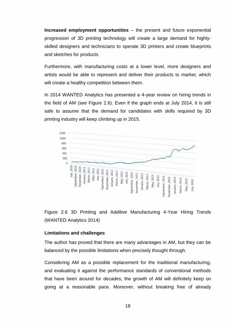
In 2014 WANTED Analytics has presented a 4-year review on hiring trends in
the field of AM (see Figure 2.6). Even if the graph ends at July 2014, it is still
safe to assume that the demand for candidates with skills required by 3D
printing industry will keep climbing up in 2015.
Figure 2.6 3D Printing and Additive Manufacturing 4-Year Hiring Trends
(WANTED Analytics 2014)
Limitations and challenges
The author has proved that there are many advantages in AM, but they can be
balanced by the possible limitations when precisely thought through.
Considering AM as a possible replacement for the traditional manufacturing,
and evaluating it against the performance standards of conventional methods
that have been around for decades, the growth of AM will definitely keep on
going at a reasonable pace. Moreover, without breaking free of already
19
predicted restrictions, the unique benefits of additive manufacturing will be
weakened and unrealized.
Demerits of additive manufacturing
Loss of Manufacturing Jobs – contradictory to the growing market of
engineering jobs that are required by AM, general tendency regarding
manufacturing jobs, unfortunately, is going down, with more technology
occurring in homes or offices (Greenberg 2014). This concerns a lot of
economies of the Third World countries since those depend mostly on this kind
of low-skilled labor.
Violation of copyrights – this kind of technologies might be a reason of many
ethical concerns, which are the results of the general misusing of the
technology. With the limitless ability to print whatever wanted and needed,
people can easily forget that some products are protected with patents and
copyrights, which can lead to the raise of piracy that is treated as an act of
crime.
By restricting the access to the available 3D designs of the protected work can
help to protect the copyrights. And yet, with the amount of information in the
Internet and the speed of spreading, it is nearly impossible to protect all the
existing design files in the global network.
Printing weapons – if the world is excited about all the current and potentially
good things that will help people to fight their personal obstacles or make life
easier, less people pay attention to the fact that alongside of that, dangerous
and harmful items (plastic guns, knives, etc.) has the same ability to be
designed and printed. And by using materials that cannot be detected,
dangerous weapons could easily be brought in any kind of public places. We
can doubt the legitimacy of 3D printing in a world where terrorism keeps
growing and connect individuals all around the world.
Production of unnecessary stuff – as 3D technology is an exciting thing to
try, hobbyists and regular consumers might just want to have fun printing things
that they do not really need and that do not have any impact on people‘s
everyday lives. This could result in a huge number of unnecessary products and

20
items that will go to waste, which is bad either for wallets and/or the
environment. Increasing waste will not help the crucial problem of recycling we
have had for a while now.
What is still holding AM back?
There are still things worth mentioning that cannot be seen as definite demerits,
in the author‘s personal opinion, but they definitely have a negative effect on an
even faster development and further outspread of additive manufacturing. In her
article, Lyndsey Gilpin (2014) helps to understand what factors keep 3D printing
from fulfilling its tremendous promise.
The world is awaiting the breakthrough consumer model claims Gilpin
(2014). Extensive user acceptance of 3D manufacturing will happen once 3D
printers will drop in price, making it available for different customer levels.
Currently, the market can already provide printers for more (for example, $5999,
Stratasys Mojo, on Amazon.com) or under $1,000 (see Table 2.1). The principle
is clear and simple: the higher the price, the better the result. Relatively cheap
printers do exist (see Table 2.1: $249, MOD-t), but then the quality of the
product and the reliability of the 3D printer comes with a question mark.
Table 2.1 3D Printer‘s Price Comparison (BGR 2014)
Reliability is definitely one of the key specifications when it comes to
machinery and technologies. And any kind of machine or device might be
unstable from time to time. For a device such as a 3D printer, which has to
operate with high precision, instability cannot be tolerated. Of course, expensive

21
device in combination with frequent service will give the user what is needed.
This means, it will involve unpredictable and demanding investments. In
comparison with what has to be spent on maintenance and materials, the price
to be paid for 3D printer itself is not the biggest investment to make.
What is also important in such thing as technology is safety. AM is not an
exception in this question.
There are some points to be concerned about while 3D printing.
Because of the working principle of mostly all of 3D printers, they reach relatively high temperatures while operating, bringing up obvious risks and danger.
Air quality (indoor or outdoor) due to the emissions produced from some printers (SLS, in particular) is relatively low.
Powder-based materials are messy and potentially explosive. Also, printers based on this kind of materials produce a subsequent amount of waste.
The technology itself is not foolproof either, and once it gets in the hands of
people who have no idea how to operate it right, it is already enough for a
reason to be concerned.
It has been repeatedly said that additive manufacturing is great for complex and
detailed components. Despite of that, it is impossible to print large models in
one piece. Moreover, sometimes a model needs more than just two smaller
pieces, which requires some assembly manual work afterwards.
But, once the object has been created, it does not necessarily mean it is done.
Depending on the material, some additional procedures have to be done:
varnishing, cutting out of the support material, etc. Any additional process
causes complexities of completing the 3D object, and it definitely requires
some skill or, at least, knowledge, which not all of the 3D printer‘s users have.
Complex design as good as it is comes with complex design softwares, which
are hard to handle without a proper formation. Additive manufacturing is not just
about printing the object – it is more about designing it with the help of specific
software. And, usually, the software requires some skills to be operated. The
combination ―design + printing‖ might take some time and patience. This is the

22
reason why the technology is still mostly used by professionals and hobbyists-
enthusiasts.
During his TED-talk, Joseph DeSimone (2015), the CEO of Carbon3D, also
refers to some facts. Even though 3D printing is suitable for mass
customization, it is still ―[…] takes forever to manufacture series of lots of
objects […]”. It now takes from a couple of hours to a couple of days to
complete the manufacturing process, but if 3D printing is intended to change the
industry the parts need to be printed in a matter of a couple of minutes.
Moreover, the layer-by-layer process leads to defects in mechanical
properties. As a result, properties such as strength, tensile strength, Young‘s
modulus, etc. might be affected, making a part mechanically weak.
Future of additive manufacturing
There is no doubt that additive manufacturing is one of the most promising
trends nowadays with an outstanding potential in the prototyping, modeling and
consumer markets. The speed of development and rise in customer interest are
pushing technology to offer easier-to-use tools and materials that produce
consistently high-quality results. As the products rapidly evolve, organizations
will increasingly utilize 3D printing's potential. Growth in the market at the
industrial side is progressively regulating this technology as new opportunities
are discovered and new materials are introduced.
Forecasts and predictions
Even though additive manufacturing is related to technology, its current and
future implications in business are relatively significant. It was said by Stephen
Prentice (2014), one of the Gartner‘s analysts, that they believe that 3D printing
is one of the emerging technologies, which will significantly impact business
over the next five years.
The author has already slightly mentioned the growth of the global market for
the years to come. But just this is not enough to describe the trends that provide
significant opportunity quickly coming into focus.

23
There are some forecasts that should be considered when talking about the
future of AM:
According to Pete Basiliere (2014), there is a compound annual growth
rate (CAGR) of 106.6% in worldwide unit shipments of 3D printers from
2012 to 2018 (2.3 million 3D printers will be shipped in 2018 in
comparison to roughly 130,000 shipped in 2014), and revenue growth of
87.7% (in 2018 3D printing final-users will spend over $13 billion in 3D
printers and 3D printing materials compared to over $1 billion spent in
the past year) for the forecast period (see Figure 2.7).
Figure 2.7 Worldwide 3D Printer Forecast (Gartner 2014)
As mentioned earlier in Chapter 1 (see Table 1.1), the growth of the 3D
printing market represents a clear market opportunity for the years to
come.
Primary AM market includes AM systems, materials and services.
According to Roland Berger‘s report (2013), the AM global market sales
in 2012 were distributed between three components according to the
Figure 2.8. A breakdown of the market according to printer sales
(systems), services, and material sales is shown below for 2014 (see
Figure 2.9).

24
Figure 2.8 Breakdown of the Market for 2012-2013 (Roland Berger 2013)
Figure 2.9 Breakdown of the Market for 2014 (3D Printing 2014-2025:
Technologies, Markets, Players 2014)
In terms of materials, photopolymers tend to have the highest market
revenue generating over $200 million which is expected to grow and
reach the market revenue of approximately $600 million by 2025 (see
Figure 2.10).
Figure 2.10 Materials Market Predictions 2013-2025 (IDTechEx 2013)
Although the other materials markets will gain market share in terms of
tons produced, driven mostly by the intention to move away from
prototyping towards focusing on direct critical part production (IDTechEx
2013). When this will occur, additive manufacturing is going to completely
change how design and production of metal parts are conceived.

25
Companies and laboratories will need to turn their attention to the
synthesis, processing, properties, and performance of the materials that
will fundamentally determine the success or failure of direct part
production (Wohlers 2011).
According to the article by Louis Columbus (2015), the contributor of
Forbes, based on the report by Pierfrancesco Manenti (2014), additive
manufacturing is one of the eleven most disruptive technologies (see
Figure 2.11). The Economist magazine (2012) linked the additive
manufacturing to the start of the third industrial revolution. As
manufacturing goes digital (as well as office equipment, music,
telecommunication, etc.) a ‘third great change’ (the first took place in
the late eighteenth century in Britain when textile industry was
introduced to mechanization; the second – in the early twentieth
century in America with the assembly line that allowed mass
production) is now gathering speed. The new step in industrial
revolution will allow things to be made economically in much smaller
numbers, with more flexibility and with a much lower input of labor.
New materials, user-friendly machines, smart softwares and new
collaborative manufacturing services available online will achieve an
all new kind of production efficiency.

26
Figure 2.11 Most Disruptive Technologies (Forbes 2015)
It was mentioned in Chapter 2.4.1 that the development of 3D printing
will affect the economies of Third World‘s countries because a lot of them
are based on manual and low-skilled manufacturing labor. In particular,
as 3D printing takes hold, the factors that have made China the
workshop of the world will lose much of their force.
D‘Aveni (2013) said that China will not be a loser in the new era, but
it will have to give up on being the world‘s manufacturing
powerhouse. The strategy that has given it such political heft will not
serve China in the future. With the additive manufacturing available,
manufacturing will once again become a local industry with products
being manufactured near raw materials or markets.
Possibilities for the near future
The adoption of the 3D printing is getting increasingly mainstream. The
application range of additive manufacturing is growing as materials improve
and costs decrease, so what people can barely imagine today will become
possible in the future (see Figure 2.12).

27
Figure 2.12 Additive Manufacturing Applications Timeline (Royal Academy of
Engineering 2013)
Perhaps, one of the greatest areas of the potential growth of additive
manufacturing is medicine. One of the key reasons for this is that the
capabilities of additive manufacturing align well with the needs of medical
technology medical device segment claims Snyder & Co. (2014). Many medical
devices, such as hearing aids, dental crowns, and surgical implants, are
relatively small in size and therefore suitable for the production available
through common AM systems.
There are already real examples of the results provided by cooperation of the
medicine and additive manufacturing. In 2012, an 83-year-old Belgian woman
was the first one to receive the 3D printed jaw bone, a transplant that was
tailored specifically for her facial structure. In March 2014, at Universitair
Medish Centrum Utrecht, a 22-year-old woman from the Netherlands, who was
28
suffering from a chronic bone disorder, had the top section of her skull removed
and replaced with a 3D printed implant.
Scientists are working on creating 3D printed organs with a further
implantation, replacing tissues and developing cell therapies, so they can
achieve the main goal – to cure disease saying De Waele (2014) in his article.
Optimistically, the humanity is not so far away from implementing those
innovations as a common practice to save lives.
It is also impressive how additive manufacturing influences building design
and construction. In the United Kingdom, the D Shape Printer, specializing in
Freeform Architectural 3D printing, is now commercially available. Capable of
printing structures that are 6x6x6 meters, it can be used to print any kind of
features. This can be used for printing single-handed bus stops, park benches,
fountains, small swimming pools, furniture, etc.
In 2014, a Chinese firm, WinSun, has also begun printing houses using a ―sand,
concrete and glass fiber ‗ink‘‖ made from industrial construction waste. It
recently produced 10 buildings in Shanghai (10 meters wide and 6.6 meters
high) in a day at a cost of less than $5,000 each.
Designer Alastair Parvain (2013) has the strong belief that it is possible to make
architecture accessible to 100 percent of population instead of just 1. He is part
of the team behind WikiHouse, an open-source construction kit. Basically, that
is a library of 3D models and cutting files that will allow anyone anywhere using
a CNC machine and plywood, to ―print‖ out the parts for their own house and
then assemble them together just in a group of 2+ people. But it is still an early
experiment as Parvin calls it.
In the author‘s opinion, 3D architecture might be considered as the cheaper,
faster and safer, alternative to more traditional structure. But before it will
actually become one, it will still need to go a long path gaining the strength and
assurance.
The aerospace and defense industry is one of the earliest adopters of
additive manufacturing (Coykendall & Co. 2014) and it keeps adopting more
and more 3D printing and rapid prototyping technologies to develop aircraft

29
parts to reduce material costs, drop off labor content, decrease the weight of
parts and increase availability at the point of use. As a matter of fact, one of the
major players in the aerospace domain, Boeing, already utilized 3D printing
technology extensively and printed over 22,000 parts across 10 types of military
and commercial aircrafts by 2013 (Busscher 2015).
Current applications of 3D printing in the industry of aerospace and defense
vary from manufacturing simple objects to complex parts (see Figure 2.13),
from armrests to complex engine parts (Coykendall & Co. 2014). More complex
applications such as printed wings for aircrafts are foreseeable in the future. But
still, as additive manufacturing is a technology that is evolving fast, it is hard to
predict what else might be added to this ―potential‖ list in the nearest future.
Figure 2.13 AM Applications in the A&D Industry (Deloitte Analysis 2012)
Another industry among the most promising might also be the most surprising
one. The printing of food is definitely one of the areas of 3D printing that is
hardly believable. The introduction of science and technology in the kitchen,
also called molecular gastronomy, may revolutionize the way we eat and
prepare food in the future.
Basically, the general process is not different from creating any other kind of
product with the help of a 3D printer. The printer‘s ‗inks‘ are replaced with foods
in a fluid form and the food is similarly ―printed‖ from an electronic blueprint or
sketch created in the software or application. This provides a huge creative
scope: design, totally new textures and new flavors can be created and
fashioned.

30
In his article, De Waela (2014) is briefly acquainting people with the food
printers (like the Foodini or the Candy) that have been already introduced and
will be sooner or later available on the market. 3D Systems developed
SugarLabs to open the mindsets of people and experiment new ways of
consuming sugars and cakes.
It is not only about the technology finding its place and purpose in different
industry sectors, it is also about being accepted and respected by the worlds‘
leading brands and enterprises.
Wohlers (2015) said that the change in the commercial 3D printing over the
past two years is unlike anything the world has seen since 1988. Major
corporations are making commitments to 3D printing. The earliest adopters of
the technology were mostly related to the world of manufacturing and industry,
such as Chrysler, General Motors, Pratt & Whitney, and Texas Instruments.
However, the recent wave of big companies and brands falls into another
category: eBay, Amazon, General Electric, Adobe, Nike, American Pearl,
Hershey‘s, Toys ‖R‖ Us, etc (see Figure 2.14). The attention and influence now
shifts from the companies that manufacture these amazing devices to a diverse
variety of industries where the technology is meeting distribution and practical
applications.
Figure 2.14 Ten Most Influential Companies on 3D Printing (Future
Technologies 2014)

31
‖A vote of confidence from major software companies, large e-commerce sites, and retail outlets has propelled 3D printing to a new height. It’s uncertain whether these companies will succeed with their initiatives, but the technology is finally getting the attention and respect it deserves.‖ claims Wohlers (2015).
Prototyping
Prototyping – WHAT and WHY?
Entrepreneur (1996) refers to Jacquelyn Denalli‘s (1993) definition from her
Inventor's Circle—Terms of Invention, claiming that a prototype is an exact
replica of the product as it will be manufactured, down to the last detail,
including color, graphics, packaging and instructions. In the world of technology,
it can also be considered as one of the essential early steps in the process of
development and innovation.
Prototyping is a tempting idea for large and complex systems to help
determining the requirements, test the design and draft possible solutions, when
there is no manual process or equipment available.
The goal of prototyping is to provide a system with overall functionality. It does
not necessarily need to embody all of the product's final qualities; it only needs
to clearly emphasize the most important aspects of the model.
Types
In general, prototypes are falling into different categories according to their
functions or a purpose they are about to follow. Based on the issue of
Entrepreneur written by Tomima Edmark (1997), the author has distinguished
three most important categories of prototyping.
Working model
This prototype (also called a breadboard) serves to demonstrate the main
concept alongside with its basic working principle. As it mostly concerns the
representation of the idea, the working model keeps aesthetics in background.
Danelli (1993) also mentioned that it does not even have to work well. This
prototype is used in the early stages of product development to demonstrate
functionality, identify which design options will work, and communicate the idea

32
to potential manufacturers. For this step, AM technologies do not necessarily
have to be used. It is just enough to find a way to show how your concept
should operate. Yet, if there is a need in fast functional representation, SLS or
FDM might be considered as a good way out.
Figure 3.1 Samsung Printer Origami Prototype (Digital Trends 2013)
Presentation prototype
A presentation prototype combines the functionality of the product with the
overall appearance (see Figure 3.2), putting aesthetics at the top of the list of
priorities. This type of prototype is created to be presented to potential investors
or for promotional purposes (marketing, sales pitches, photo-shoots, packaging
mock-ups, etc). In this case, a prototype has to be highly correlated to the
actual product in appearance, material, dimensions and feel as well as
representing of what the product is able to do. To achieve it, several AM
technologies can be used depending on the specific requirements. Most of the
companies and trademarks that are dealing with prototyping, such as WayKen
or Hyphen, rely on SLA technology due to its high accuracy and excellent
surface finish that can be easily painted if needed. FDM or SLS is less aesthetic
but these technologies are suitable for hard handling or intense heat of a
spotlight.

33
Figure 3.2 Presentation Prototype of a Playground (Hyphen 2015)
Pre-production prototype
A pre-production prototype fully resembles the look and functions of the final
product (see Figure 3.3). According to Nebraska Business Development Center
(2015) the step of creating a pre-production prototype result in knowledge about
the manufacturability of the product, the manufacturing processes,
maintainability and reliability, installation and production costs, safety and
environmental factors, time schedules, and regulatory requirements. This
prototype gives everyone a chance to inspect the product for the last design
flaws and make last-minute changes before the real product is ordered. It is
usually the last step in product design process before the full-scale
manufacturing begins. In author‘s personal opinion, the best way of creating the
pre-production prototype is to combine different AM technologies together in
order to achieve the best model possible in terms of functionality and
aesthetics.

34
Figure 3.3 Barber-Nichols Model BNF-01-000 Pre-Production Prototype Fan in Expeditionary Fighting Vehicle (EFV) (Barber-Nichols Inc. 2015)
Rapid prototyping
There is one essential type of prototyping which, in the author‘s personal
opinion, can be pointed out individually – rapid prototyping (RP). It is commonly
referred to as a group of techniques used to quickly fabricate a complex-shaped
scale model of a physical part or assembly with the help of computer-aided
design program (Rubio & Filho, 2013, p.831).
Brenda Cole (2014) states that RP should be considered as a 3D visualization
tool for the items that have been digitally accomplished. As a regular
prototyping it can be used to test the efficiency and functionality of a part or
product design before it gets to be manufactured.
Apart from testing and visualization, Rubio and Filho (2013, p.832) consider that
rapid prototyping might also be used in order to:
increase the effective communication; lower the development time; decrease costly mistakes; minimize sustaining engineering changes; extend the product lifetime by adding necessary features and eliminating
redundant features early in the design.
Clay Thomson & Preston Smith (2000) and George Hill (2014) defined several
rather similar key elements in the success of the product development. First,
Thomson & Smith (2000) concluded that the success depends on the ability to

35
shorten the iterative product-development loop, to quickly move from idea to
prototype, so that the final product can be released. In their opinion, the speed
is what can make rapid prototyping one of a major element of the performance.
More recently, Hill (2014) argued that the speed of prototyping in the process
and the success of the final product are two functions positively correlated to
each other, as rapid prototyping can allow more prototypes and therefore, more
trials to correct and optimize the product to its best.
RP vs. AM: is there any difference?
Nowadays, it is becoming more and more common to create prototypes with the
help of additive layer technology, commonly called 3D printing. With the
popularity of 3D technology growing with a remarkable speed, for the author,
the question whether it can be compared to rapid prototyping popped out
immediately.
Robert Dehue (2012), a contributor of 3dprinting.com, notes that rapid
prototyping and 3D printing are often used alongside with each other. He claims
that they definitely have similarities among which one of the most important is
the manufacturing method – both technologies build a part one thin layer at a
time.
What makes them different, according to Andy Marin (2014), is the fact that 3D
printing (or additive manufacturing) is the process, and rapid prototyping is the
final result of this process, as rapid prototyping is only one of many applications
under the umbrella of additive manufacturing.
Model evaluation
Based on the theoretical knowledge gained through the current study,
evaluation of the 3D model and prototype can now proceed in order to figure out
what has to be done by the author through the empirical part.

36
General information
The construction of the model consists of a multiple-pole tooth-coil PMSM
unified with a planetary gear in a one single system. The layout of the structure
with all the included parts is introduced in Figure 4.1.
Figure 4.1 Layout of the motor structure (Integrated Hub-Motor Drive Train for
Off-Road Vehicles 2014)
In the suggested design, the rotor of the electric motor is adjusted to the sun
gear that is a part of the planetary gear set (see Figure 4.1, parts 2 and 3). As
the two-step gearbox is used, it is possible to obtain 2 types of gear ratio:
The direct gear ratio (1:1) can be obtained when clutch 1 is activated. In this case, the power transmission goes the following path: rotor – sun gear – activated clutch – output shaft (see Figure 4.2). This allows the planet carrier to rotate freely and keeps the ring gear fixed (see Figure 4.1, parts 7 and 8).

37
Figure 4.2 Power Transmission Path For The Direct Gear Ratio (Integrated Hub-Motor Drive Train for Off-Road Vehicles 2014)
The reduction gear ratio depends on the teeth number of the ring gear, the sun gear and the planetary gears. With the clutch 2 activated, the power is following the other way: rotor – planetary gear – planetary carrier – activated clutch – output shaft. For this case, typical ratio values that can be achieved easily would vary from 1:2 to 1:10 (Integrated Hub-Motor Drive Train for Off-Road Vehicles, 2014).
For the tractor application, a gear ratio of approximately 1:4 would be
appropriate. Activated reduction gear would enable high torque and traction
force capacities at low speeds, while the direct gear ratio would provide high
enough speed. (Integrated Hub-Motor Drive Train for Off-Road Vehicles, 2014)
Pros and cons of the model
Advantages and disadvantages, which matter for the particular study, can be
found in both, the 3D model and several current prototypes.
3D model
The studied 3D design is perfectly suitable for a straightaway manufacturing,
but does not fulfill all the necessary requirements of being a correct prototype
for investors to fall for it.
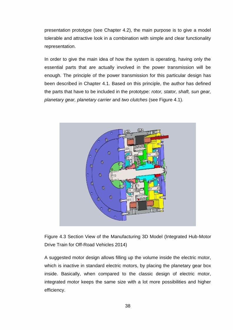
What can be easily noticed on the picture of the studied integrated model (see
Figure 4.3) is its definite complexity. As the author is intended to create a
38
presentation prototype (see Chapter 4.2), the main purpose is to give a model
tolerable and attractive look in a combination with simple and clear functionality
representation.
In order to give the main idea of how the system is operating, having only the
essential parts that are actually involved in the power transmission will be
enough. The principle of the power transmission for this particular design has
been described in Chapter 4.1. Based on this principle, the author has defined
the parts that have to be included in the prototype: rotor, stator, shaft, sun gear,
planetary gear, planetary carrier and two clutches (see Figure 4.1).
Figure 4.3 Section View of the Manufacturing 3D Model (Integrated Hub-Motor
Drive Train for Off-Road Vehicles 2014)
A suggested motor design allows filling up the volume inside the electric motor,
which is inactive in standard electric motors, by placing the planetary gear box
inside. Basically, when compared to the classic design of electric motor,
integrated motor keeps the same size with a lot more possibilities and higher
efficiency.

39
Current prototypes
The author has been provided with two different prototypes that had already
been engaged with a project. There are several unambiguous advantages of
two current prototypes that can be easily defined from the first sight. Based on
the information received from the model estimation, the author can figure out
what has to be improved in her upcoming design.
Figure 4.4 Current Presentation Prototype (#1) (2015)

40
Figure 4.5 Current Functional Prototype (#2) (2015)
First of all, both introduced constructions are noticeably compact. The reason
for that has already been mentioned by the author in Chapter 4.2.1. In general,
it is beneficial in terms of space saving, transportation and aesthetics.
Secondly, the models consist of a shaft, a stator, a rotor, sun and planetary
gears, a planetary carrier and two clutches (see Figures 4.6 and 4.7), which
proves the point of the author about what members should be necessarily
included. Once two models have been analyzed and their functional
representation has been seen, it became clear that there is no need for adding
any extra parts to the prototype. However, prototype #1 also includes a lot of
screws and other small metal parts that are adding extra weight to the model
and might not get along with the new design. In this case, they all need to be
removed. Prototype #2 also includes a mechanism that is built to actuate
clutches, which has to be removed as the author is intended to come up with
her personal idea of engaging clutches.

41
Figure 4.6 Side View of the Prototype #1 (2015)
Figure 4.7 Side View of the Prototype #2 (2015)

42
Thirdly, the section view of both prototypes has been compared. It has become
clear that the section view of prototype #1 (approximately ¼ of the model) is
creating one of the most available ways to look inside of the model and, at the
same time, keep it as simple and complete as possible.
However, none of these prototypes is as perfect as it may seem. Even if
prototype #1 is made of plastic and is rather compact, it is still including some
real parts (e.g. output shaft, bearings, screws) made of metal. This increases
the weight of the structure and requires a proper support. Such a heavy
prototype is not practical in terms of transportation. The current V-shaped
support (see Figure 4.5) is good enough to fulfill the purpose of holding the
system; indeed it is quite unstable and might easily fall on the side.
Contrary to the first one, prototype #2 is 3 times more compact and significantly
lighter although it is still as functional as the bigger one. It can be seen as the
kind of a pocket version of the electric motor but it is fragile and can be easily
broken. Moreover, it does not really attract to itself due to the lack of color and
tiny dimensions.
Ideas for improvement
At first, the focus of the author is directed towards the improvement of the
prototypes‘ disadvantages. For this purpose, the author has to answer the
following questions:
1. What kind of a design can keep the support strong, reliable and good-looking at the same time?
2. How to activate clutches? 3. What section view will provide the best way to observe the model?
Based on the authors‘ knowledge gained through the classes of statics and
physics as well as personal experience, it was decided that there would be
nothing better than to create some simple and solid base, where elegance
would go side-by-side with functionality and reliability.
One way or another, clutches have to be activated with the help of mechanical
power. The easiest way is to simply use fingers in order to move clutches or the
mechanism that is supposed to activate them. As the author is intended to
43
change the design that has been suggested previously, the mechanism itself
has to be changed but the idea of a manual activation can remain the same.
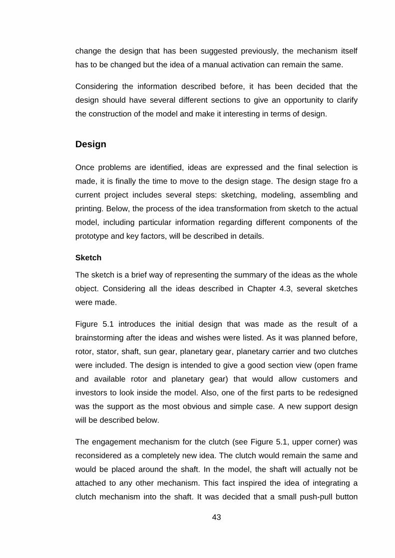
Considering the information described before, it has been decided that the
design should have several different sections to give an opportunity to clarify
the construction of the model and make it interesting in terms of design.
Design
Once problems are identified, ideas are expressed and the final selection is
made, it is finally the time to move to the design stage. The design stage fro a
current project includes several steps: sketching, modeling, assembling and
printing. Below, the process of the idea transformation from sketch to the actual
model, including particular information regarding different components of the
prototype and key factors, will be described in details.
Sketch
The sketch is a brief way of representing the summary of the ideas as the whole
object. Considering all the ideas described in Chapter 4.3, several sketches
were made.
Figure 5.1 introduces the initial design that was made as the result of a
brainstorming after the ideas and wishes were listed. As it was planned before,
rotor, stator, shaft, sun gear, planetary gear, planetary carrier and two clutches
were included. The design is intended to give a good section view (open frame
and available rotor and planetary gear) that would allow customers and
investors to look inside the model. Also, one of the first parts to be redesigned
was the support as the most obvious and simple case. A new support design
will be described below.
The engagement mechanism for the clutch (see Figure 5.1, upper corner) was
reconsidered as a completely new idea. The clutch would remain the same and
would be placed around the shaft. In the model, the shaft will actually not be
attached to any other mechanism. This fact inspired the idea of integrating a
clutch mechanism into the shaft. It was decided that a small push-pull button
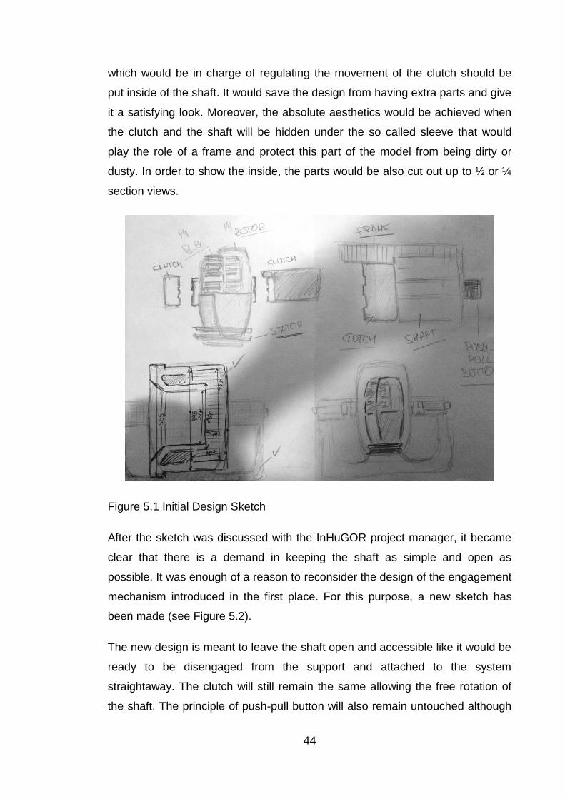
44
which would be in charge of regulating the movement of the clutch should be
put inside of the shaft. It would save the design from having extra parts and give
it a satisfying look. Moreover, the absolute aesthetics would be achieved when
the clutch and the shaft will be hidden under the so called sleeve that would
play the role of a frame and protect this part of the model from being dirty or
dusty. In order to show the inside, the parts would be also cut out up to ½ or ¼
section views.
Figure 5.1 Initial Design Sketch
After the sketch was discussed with the InHuGOR project manager, it became
clear that there is a demand in keeping the shaft as simple and open as
possible. It was enough of a reason to reconsider the design of the engagement
mechanism introduced in the first place. For this purpose, a new sketch has
been made (see Figure 5.2).
The new design is meant to leave the shaft open and accessible like it would be
ready to be disengaged from the support and attached to the system
straightaway. The clutch will still remain the same allowing the free rotation of
the shaft. The principle of push-pull button will also remain untouched although

45
now it will be attached to the vertical beam of the support. The clutch will be
moved with the help of a lever that is attached to the support with its bottom and
to the clutch with the top. The button will activate the clutch by pushing the lever
forward, which will also create some extra support. Once the clutch will be
disengaged, the lever will be pulled back and fixed parallel to the support beam.
This will save some space and ensure a good-looking exterior by avoiding too
many details.
In general, it was decided that the design does not need any additional
improvements and corrections other from the ones that have already been
mentioned in the initial sketch.
Figure 5.2 Final Design Sketch
Modeling
Modeling is one of the most complicated parts in the design process. This is the
stage where the ideas are finally transformed into shapes. It was decided that
the real prototypes will be taken as the foundation of the new models, which will
be redesigned and simplified throughout the stage of modeling.

46
It was clarified earlier that the model is desired to be compact and
transportable. For that reason, the prototype was distinct to be approximately
1:2 scale of the original motor, which would allow having a perfect scale in
terms of mobility and image. All the sizes have been measured and evaluated,
and the succeeding models were created based on the design material
provided by the Drive! Team.
Support
It was decided that it would be easier to start from a simple, basic part that does
not need too much time or too many details to pay attention to. For this reason,
the support structure came naturally to be a part to start with.
As it was settled before, the support has to be as simple as possible,
accomplished and secure. To achieve this, the following elements were created:
U-shaped support with a wide bottom that allows to keep the design simple and reliable at the same time;
Fillets that soften the edges providing the design with a streamline body and attractive exterior design (see Figure 5.3).
The side beams will also be used to support the mechanism that will move the
clutch along the shaft, so the additional improvements might take place during
the assembly stage.
Figure 5.3 Initial Support Structure Design for the Prototype

47
During the design, it was decided that the support might need some additional
structural elements to provide extra stiffness and reliability. So, stiffness ribs
were added on the sides of the beams. They give an opportunity not to use any
extra space and keep the structure quite elegant, allowing it to have more
strength at the same time. Stiffness ribs are not only providing some additional
support for the structure, but also giving the opportunity to play a little with
shapes in order to create a unique element (see Figure 5.4).
Figure 5.4 Updated Support Structure Design
Shaft
It would be logical to keep the design process in an order that would follow the
assembly process. Such principle will allow doing two things simultaneously
would result in time savings and allow necessary changes straightaway in the
model.
The shaft is the next core element of the prototype. It is the backbone of the
whole structure as it will connect and keep all the elements together. The shaft
is not supposed to have a complex design because it will only complicate the
process of printing and might cause some additional troubles along the way.

48
In the original shaft model there is a difference between two ends of the shaft.
Alongside with that, the parts where clutches are meant to be placed have more
teeth (25 instead of only 5).
In the simplified shaft design (see Figure 5.5), both ends are made to be equal
in order to fit in the support, and the amount of teeth is reduced. However, the
edges where clutches will be attached were prolonged to allow a better
movement of a clutch. Moreover, they were kept in different dimensions to give
uniqueness to the prototype and make a difference on their ratio. In general, the
simplifications should allow manufacturing of the shaft, either traditional or
additive, to be significantly easier.
Figure 5.5 Final Shaft Design
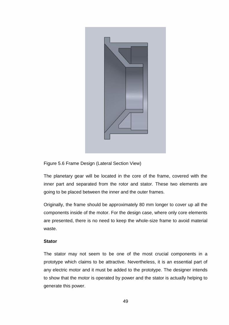
Frame
Simplicity is one of the main criteria for the current design. The frame has an
elementary design where two parts (outer and inner frames) are already
integrated together which saves the material and decreases the amount of parts
needed for assembly (see Figure 5.6).
49
Figure 5.6 Frame Design (Lateral Section View)
The planetary gear will be located in the core of the frame, covered with the
inner part and separated from the rotor and stator. These two elements are
going to be placed between the inner and the outer frames.
Originally, the frame should be approximately 80 mm longer to cover up all the
components inside of the motor. For the design case, where only core elements
are presented, there is no need to keep the whole-size frame to avoid material
waste.
Stator
The stator may not seem to be one of the most crucial components in a
prototype which claims to be attractive. Nevertheless, it is an essential part of
any electric motor and it must be added to the prototype. The designer intends
to show that the motor is operated by power and the stator is actually helping to
generate this power.

50
The simplified 3D model of the stator (see Figure 5.7) consists of:
a stator core;
a stator (field) winding.
Figure 5.7 Stator Design
Usually, when the core is used, it has to be laminated or have some additional
lamination of its sides in order to reduce the eddy current loss. As there will be
no current running through the prototype, the laminations can be neglected.
This will save the material and decrease the amount of elements in the final
assembly.
Basically, the core is made out of the number of slots that are intended to carry
the field windings. In the original project, a double-layer three-phase tooth coil
winding is used. One of the given reasons for its usage by the project team was
its very compact end-windings of this certain type. However, it is hard to create
a perfect imitation of the coil with the computer software. Indeed, the idea of the
winding compactibility was saved and adapted in the design.
Rotor
A rotor is another crucial component of the PMSM. Contrary to the stagnant
stator, this element of the motor is rotational, and its rotation is caused by the
windings of the stator. Nevertheless, the structure of both components might

51
seem similar. The rotor consists of a laminated core with built in slots that might
be used to carry conductors.
For the current project, original rotor was designed to have a totally smooth
surface to minimize the viscous loss. Even though there will be no viscous loss
occurring in the model, a nice surface finish cannot be a disadvantage in
achieving the goal of a good-looking prototype.
In the model developed for the prototype (see Figure 5.8), all the crucial
components of the rotor can be found. Unfortunately, the slots cannot be seen
on the picture as the edge of the laminated core is covered by another element
of the part.
Figure 5.8 Rotor Design
Planetary gear
A planetary (also called epicyclic) gear is a gear system that consists of:
planet (outer) gears; revolving about a
sun (central) gear;
annulus (outer ring gear);
carrier (movable arm).
Usually, the planet gears are spinning around a central gear and are attached to
a movable arm or carrier that may rotate relative to the sun gear, which meshes

52
with the planet gears. The following gear system is simple as it consists of one
sun, one ring, one carrier, and one planet set.
Before designing, some calculations have to be done in order to figure out the
gear ratio or the number of teeth needed for every part of the system except of
the carrier.
Based on the formulas suggested by Matthias Wandel (2013), a founder and
contributor of woodgears.ca, and the information gathered from the technical
data of the InHuGOR project, the following results were found.
In order to make the gear system work properly, it is important that the number
of teeth in the ring gear evens up the number of teeth in the sun gear plus twice
the number of teeth in the planet gears.
R = 2 × P + S (5.1)
Wandel (2013) is also giving the formula that helps identifying the gear ratio for
the system:
(R + S) ×Ty = R × Tr + Ts × S (5.2),
where
R – Number of teeth in the ring gear; S – Number of teeth in the sun gear; P – Number of teeth in the planet gear; Ty – Rotation speed of the carrier; Tr – Rotation speed of the ring gear; Ts – Rotation speed of the sun gear.
In this particular case, it is known that the ring gear is fixed, which means that Tr
equals 0. From this, the formula can be reconsidered as
(R + S) ×Ty = Ts × S (5.3).
The following equation makes it possible to calculate the rotation speed either
for the sun gear or the carrier.
Ty = Ts × [S/(R + S)] (5.4a)
Ts = [(R + S)/S] ×Ty (5.4b)

53
It is easier to assume that the gear ratio can be calculated as
S/(R + S) (5.5).
It was mentioned before that the gear ratio is approximately 1:3,6 (see Chapter
3.1). Figure 5.9 represents the plot for rotation speed against the time, from
which the information regarding the nominal rotation speed for the sun gear and
planet carrier was extruded. It can be assumed that the rotation speed of the
sun gear (Ts) is 1200 rpm.
Figure 5.9 Rotation speeds during a gear shifting cycle (Integrated Hub-Motor
Drive Train for Off-Road Vehicles 2014)
It was decided that it would be a good decision to take into consideration some
relevant data that has already been checked and used by the project team.
According to the information found in the project documentation, the data for the
ring gear was extruded and the number of teeth, R, which is equal to 58 was
used for the further calculations.
Equation (5.5) is used to calculate the missing value for the number of teeth in
the sun gear, S. Using the information from the documentation, it can be
assumed that the result for S appears as follows:
S/(58 + S)=1/3,6 S/(58 + S)=0,278 S=0,278*(58+S)
S=16,124+0,278*S

54
0,722*S=16,124 S=22.33=22
The next step would be to calculate P value. This can be easily done with the
help of Eq. (5.1).
58=2*P+22 2*P=36 P=18
The rotation speed of the carrier can be calculated according to the Eq. (4a). It
will also help to compare the calculated result with the result obtained
previously to check if the calculations were made correctly.
Ty=1200*(22/58+22) Ty=330
According to these calculations, the following design was made (see Figure
5.9). In order to mate components of the system symmetrically and enable its
proper work, the number of planet gears should be equal to 5. Although, a big
amount of gears creates more friction and complicates the imitation of the
working principle, so for the purpose of prototyping, 2 gears will be eliminated,
leaving only 3 active gears.
Figure 5.10 Planetary gear

55
Clutches
It has already been mentioned several times that clutches need some special
attention. Clutches have been the main concern of the whole design project.
In Chapter 5.1.1, the idea for the design of the clutch mechanism has already
been described. As it can be seen in the picture (see Figure 5.11), the
mechanism seems to be quite elementary. It is rather simple to understand,
simple in terms of appearance and simple of use. However, it appeared that
designing and attaching it to the system was not as simple as it seemed on the
paper.
Figure 5.11 Clutch Engaging Mechanism in Sketch
Once the problem with the attachment of the mechanism has been faced, the
design was reconsidered one more time. This time, the simplicity took the
leading role in the design. In the end, the proper mechanism was found and
attached to the system.
Figure 5.12 illustrates the idea of the final design. The ring should be placed in
the notch on the clutch and might be clamped on top with additional pins to
ensure the proper placement of the ring. The ring is attached to the tail that is
fixed in the hole on the lateral beam of the structure. In what follows, the clutch

56
can be activated with a simple move of a push-pull pin in different direction,
which allows the mechanism to lead the clutch along the shaft to engage or
disengage it from the rest of the system.
Figure 5.12 Final Clutch Engaging Mechanism Design
Such a simple design helps to avoid the overloading of the assembly and allows
a quick understanding of the working principle for the people who are unfamiliar
with such things.
Bearings
In general, the main function of the bearings is to reduce the friction and to
allow the rotation motion around the axial axis (shaft). The prototype that will be
used for commercial purposes does not need any kind of specific, expensive or
complex bearings if the only purpose of their use is to ensure the very basic
function. Basically, the required bearing type is a normal single row ball bearing.
This type of bearings is one of the most common ones as it is relatively cheap,
easy to use and works with both, radial and thrust loads.
It was decided that the model will need only 2 bearings, in the places where the
shaft is attached to the structure. As intended, they will help to rotate the shaft
around the axis and to reduce the friction between the support structure and the
shaft.

57
Figure 5.13 Normal Single Row Ball Bearing
For the current design, a required bearing type was found in the SolidWorks
Toolbox Library (see Figure 5.13) and used in order to save time for some more
crucial element design.
Assembly
The process of assembly requires the addition of several components to each
other. For the ongoing design, this process happened to be simplified by itself,
as it was done synchronously with the modeling.
The importance of assembly modeling might be underestimated. At first, the
assembly provides a great opportunity of product visualization alongside with
the ability to measure, analyze, simulate, design and redesign different
components until the desired result is reached. Moreover, it helps to figure out
problems and mistakes such as dimensions, interferences clearances, etc.
Even though they might seem irrelevant, neglecting little deviations could cause
some serious problems during the following stages of manufacturing.
The assembly modeling for this project was not an exception. This stage gave
the opportunity to reconsider and redesign the initial ideas that became
irrelevant or inconvenient for the further use. The designer also had a chance to

58
eliminate the defects and interferences that appeared during the assembly
itself.
However, necessary changes in terms of the overall appearance were also
made during this stage. Finally, the section views were added, providing the
prototype with a totally new complexion (see Figure 5.14). As it was defined
earlier in Chapter 4.3, different section views were used:
A ½ section view that was used in the frame in order to grant potential
customers with the straightaway access to the core elements of the
model. Besides, this is the best solution for a stiff and fixed element like
the frame.
A ¼ section views that were made in the stator and rotor. There is no
need for a bigger cut as the only component left that can be shown is the
planetary gearbox, but there are also other, even better, ways to access
it.
The diversity of colors is used to highlight every element and make it easy to
differentiate. In the real prototype the following color range will not be used.
In the end, the final assembly can be seen in the Figure 5.14. It might be safe to
say that the idea transformation from the draft to the actual design model is
accomplished. The model is fulfilling the requirements of the presentation
prototype that was intended to be made from the very beginning. First, it is
complete, functional and the operating principle can be easily seen and
understood by common people. Second, it is simple, aesthetic and will
complement future customers with the convenient dimensions.

59
Figure 5.14 Final Assembly of the Prototype
Conclusion
Summary and discussions
The present study has proven the importance and relevance of additive
manufacturing in today‘s world. More and more companies are employing
different 3D printing methods in order to provide their customers with unique
products and climb up the next step of technological evolution. Additive
manufacturing is a set of fast layer-upon-layer methods of making 3D
prototypes under computer control. It is no longer a futuristic theory but a
needed tool to be noticed, to stay competitive.
With the help of traditional manufacturing it is possible to conquer markets and
customers as well as investors‘ attention. With the help of additive
manufacturing and rapid prototyping, companies are telling the world that they
are ready to face new challenges and compete on the new battleground.

60
Additive manufacturing shows that technology can go side-by-side with
creativity without dropping out technical features but providing new possibilities
for their development.
The current study is grounded on both books and articles that have been used
as sources of secondary data in order to create theoretical knowledge
background on additive manufacturing and its techniques, particularly how they
work, what kind of features they have, and how beneficial they revealed to be.
Besides, a closer look has been given at some trends and predictions for the
near future in order to shape the picture of additive manufacturing possibilities
accordingly.
A major focus of the thesis was the idea of generating a detailed, efficient and
explicit prototype that would contribute to a commercial plan of the case
company. Due to the well-studied theory about additive manufacturing and
prototyping, a prototype that fulfills characteristics and needs of a good
presentation model has been created.
To achieve the goal it became necessary to do a model evaluation first. The
challenge was to analyze the 3D model of the actual PMSM to advance and
enhance the understanding of its working principle. Moreover, two current
prototypes had to be compared and assessed for the presence of imperfections
that had to be improved.
The thesis was completed by the ready-made design. SolidWorks design
software was used in the empirical part of the study, and 3D models were
generated based on the technical data and documentation provided by the case
company.
Ways to deal with dilemmas stated in the very beginning of the process were
found, the design problem of the prototype has been solved and the goals set
by the case company have been achieved. The whole process was based on
the need of the case company, but it was also a great personal experience in
the sense of learning process. From not knowing about the existence of additive
manufacturing as a separate field, and being only familiar with 3D modeling in
general, this study was rich of theoretical knowledge and gave some expertise

61
related to additive manufacturing, certainly useful in a future professional
situation.
Recommendations for further research
The current study has several delimitations. It focuses only on the goals that
would support the development of the project commercialization, in which the
case company was interested in at the time of conducting this work. So, the
whole design process pursued the objective of creating an appropriate
presentation prototype, taking into consideration requirements that need to be
completed. Other important types such as working model or pre-production
prototype were left out. Accordingly, further research and design could
investigate and present a more detailed prototype that would be suitable for
straightaway manufacturing.
The process of additive manufacturing was studied only through the first three
stages of prototyping: idea generation, sketching and modeling. Therefore,
further design process could lead to the printing stage that would allow to use
different 3D printing methods in order to achieve the most flawless prototype
suitable for the purpose of commercialization or manufacturing.
The thesis allows a detailed review on challenges that the field of 3D printing is
currently facing. As additive manufacturing is considered to be a replacement
for the traditional manufacturing, it was important to highlight the aspects that
are still holding back such a fast-developing technology. Further research could
provide some ideas and guidelines that could help to eliminate the difficulties
and highlight the benefits of the technology in order to encourage its faster
adaptation.

62
Figures
Figure 1.1 Additive Manufacturing Forecast, p.5 Figure 2.1 Selective Laser Sintering Process, p.10 Figure 2.2 Laser Stereolithography Process, p.12 Figure 2.3 Sandwich-Structured Composite, p.13 Figure 2.4 Fused Deposit Modeling Process, p.14 Figure 2.5 Relation between Cost and Complexity According To Different Manufacturing Types, p.16 Figure 2.6 3D Printing and Additive Manufacturing 4-Year Hiring Trends, p.17 Figure 2.7 Worldwide 3D Printer Forecast, p.22
Figure 2.8 Breakdown of the Market for 2012-2013, p.23 Figure 2.9 Breakdown of the Market for 2014, p.23 Figure 2.10 Materials Market Predictions 2013-2025, p.23 Figure 2.11 Most Disruptive Technologies, p.25 Figure 2.12 Additive Manufacturing Applications Timeline, p.26 Figure 2.13 AM Applications in the A&D Industry, p.28
Figure 2.14 Ten Most Influential Companies on 3D Printing, p.29 Figure 3.1 Samsung Printer Origami Prototype, p. 32 Figure 3.2 Presentation Prototype of a Playground, p. 33 Figure 3.3 Barber-Nichols Model BNF-01-000 Pre-Production Prototype Fan in Expeditionary Fighting Vehicle (EFV), p. 34 Figure 4.1 Layout of the motor structure, p. 36 Figure 4.2 Power Transmission Path for the Direct Gear Ratio, p.37 Figure 4.3 Section View of the Manufacturing 3D Model, p.38 Figure 4.4 Current Presentation Prototype (#1), p.39 Figure 4.5 Current Functional Prototype (#2), p.39 Figure 4.6 Side View of the Prototype #1, p.41 Figure 4.7 Side View of the Prototype #2, p.41 Figure 5.1 Initial design Sketch, p.44 Figure 5.2 Final design Sketch, p.45 Figure 5.3 Initial Support Structure Design for the Prototype, p.46 Figure 5.4 Updated Support Structure Design, p.47 Figure 5.5 Final Shaft Design, p.48 Figure 5.6 Frame Design (Lateral Section View), p.49 Figure 5.7 Stator Design, p.50 Figure 5.8 Rotor Design, p.51 Figure 5.9 Rotation speeds during a gear shifting cycle, p.53 Figure 5.10 Planetary gear, p.54 Figure 5.11 Clutch Engaging Mechanism in Sketch, p.55 Figure 5.12 Final Clutch Engaging Mechanism Design, p.56 Figure 5.13 Normal Single Row Ball Bearing, p.57 Figure 5.14 Final Assembly of the Prototype, p.58
Tables
Table 1.1 Global 3D Printing Market Table 2.1 3D printer‘s price comparison

63
References
3D Printing: Different Techniques, Technologies, Materials and Bureaus, 2015 . http://www.advice-manufacturing.com/3D-Printing-Manufacturing-Methods.html. Accessed on 09 February 2015.
3D Printing Industry. 2015. 3D Printing History: The Free Beginner‘s Guide. http://3dprintingindustry.com/3d-printing-basics-free-beginners-guide/history/. Accessed on 07 February 2015.
3D Printing Materials 2014-2025: Status, Opportunities, Market Forecasts. 2015. http://www.idtechex.com/research/reports/3d-printing-materials-2014-2025-status-opportunities-market-forecasts-000369.asp. Accessed on 17 February 2015.
3D Solid Modeling. 2015. Dassault Systemes SolidWorks Corp. http://www.solidworks.com/sw/products/3d-cad/3d-solid-modeling.htm. Accessed on 16 February 2015.
Barber-Nichols Inc. 2015. Pre-Production Prototypes. http://www.barber-nichols.com/services/prototyping/prototype-manufacturing. Accessed on 04 April 2015.
Busscher, P. 2015. Smart Materials: Why the Future Face of Manufacturing Matters to Investors. http://www.cityam.com/209559/smart-materials-why-future-face-manufacturing-matters-investors. Accessed on 26 February 2015.
Caliper Media, Inc., 2013. The Advantages of 3D Printing. http://calipermedia.com/the-advantages-of-3d-printing/. Accessed on 15 February 2015.
Christie Digital Systems Canada Inc. 2015. http://www.hyphenservices.com/rapid-prototyping/prototype-manufacturing/Pages/presentation-models.aspx. Accessed on 04 April 2015.
Chung, B. 2013. A 3D Printed Future: 10 Surprising Things We Could See Printed Soon. http://blog.ted.com/2013/07/29/a-3d-printed-future-10-surprising-things-we-could-see-printed-soon/. Accessed on 22 February 2015.
Cole, B. 2014. Rapid Prototyping. http://searchmanufacturingerp.techtarget.com/definition/Rapid-prototyping. Accessed on 25 March 2015.
Columbus, L. 2015. Big Data Analytics, Mobile Technologies And Robotics Defining The Future Of Digital Factories. http://www.forbes.com/sites/louiscolumbus/2015/02/15/big-data-analytics-mobile-technologies-and-robotics-defining-the-future-of-digital-factories/. Accessed on 17 February 2015.
Columbus, L. 2014. Roundup Of 3D Printing Market Forecasts And Estimates. http://www.forbes.com/sites/louiscolumbus/2014/08/09/roundup-of-3d-printing-market-forecasts-and-estimates-2014/. Accessed on 08 February 2015.

64
Conerly, B. 2014. The Economics of 3D printing: Challenges. http://www.forbes.com/sites/billconerly/2014/11/05/the-economics-of-3-d-printing-challenges/. Accessed on 06 February 2015.
Coykendall, J. Cotteleer, M. Holdowsky, J. Mahto, M. 2014. 3D Opportunity For Aerospace And Defence. http://dupress.com/articles/additive-manufacturing-3d-opportunity-in-aerospace/. Accessed on 22 February.
D‘Aveni, R. A. 2013. 3D Printing Will Change The World. https://hbr.org/2013/03/3-d-printing-will-change-the-world. Accessed on 21 February 2015.
Davidson, P. 2012. 3D Printing Could Remake USA Manufacturing. http://usatoday30.usatoday.com/money/industries/manufacturing/story/2012-07-10/digital-manufacturing/56135298/1. Accessed on 22 February 2015.
Dehue, R. 2012. Rapid Prototyping and 3D Printing. http://3dprinting.com/news/rapid-prototyping-and-3d-printing/. Accessed on 25 March 2015.
Denalli, J. 1993. Inventor's Circle—Terms of Invention. Business Start Ups Magazine.
DeSimone, J. 2015. What If 3D Printing Was 100x Faster? http://www.ted.com/talks/joe_desimone_what_if_3d_printing_was_25x_faster/transcript. Accessed on 06 April 2015.
De Waele, R. 2014. How 3D Printing Will Impact Our Future: A Rundown Of Companies To Keep Your Eyes On. http://thenextweb.com/dd/2014/09/20/3d-printing-will-impact-future-rundown-companies-keep-eyes/2/. Accessed on 19 February 2015.
Eaton, R. 2014. Additive Manufacturing Revolutionizes Architectural And Construction Fields. http://www.rapidmade.com/rapidmade-blog/2014/6/12/additive-manufacturing-revolutionizes-architectural-and-construction-fields. Accessed on 22 February 2015.
Encyclopedia of Business, 2nd Edition. Prototype. 2015. http://www.referenceforbusiness.com/small/Op-Qu/Prototype.html. Accessed on 25 March 2015.
Entrepreneur. 1996. Breadboard, Models, and Prototypes. http://www.entrepreneur.com/article/21146. Accessed on 25 March 2015.
Ermark, T. 1997. Model Approach: Creating a Prototype That Will Wow Investors. http://www.entrepreneur.com/article/14670. Accessed on 25 March 2015.
Gilpin, L. 2014. 3D Printing: 10 Factors still holding it back. http://www.techrepublic.com/article/3d-printing-10-factors-still-holding-it-back/. Accessed on 12 February 2015.
65
Green, D. 2014. Nanotechnology to outer space: top ten tech innovations of 2014. http://theconversation.com/nanotechnology-to-outer-space-ten-top-tech-innovations-of-2014-35258. Accessed on 09 February 2015.
Greenberg, R. 2014. Mixed Benefits of 3D Printing for Manufacturers and Consumers. http://cerasis.com/2014/07/25/3d-printing-manufacturing/. Accessed on 17 February 2015.
Greenough, J. 2015. The 3D-Printer Industry Is Taking Shape, With Big Implications For Product Design, Manufacturing and Marketing. http://uk.businessinsider.com/3d-printers-could-create-a-new-marketplace-for-entrepeneurs-2015-1. Accessed on 17 February.
Grimm, T. 2012. Additive manufacturing is a poor substitute. http://www.tctmagazine.com/blogs/grimmblog/additive-manufacturing-is-a-poor-substitute/. Accessed on 27 January 2015.
Hausman, K. 2014. 3D Printing For Dummies. Somerset, NJ, USA: John Wiley & Sons.
Hill, G. 2014. Is Rapid Prototyping The Most Important Element Of Innovation? http://channels.theinnovationenterprise.com/articles/is-rapid-prototyping-the-most-important-element-of-innovation. Accessed on 25 March 2015.
Information Resources Management Association. 2013. Industrial Engineering: Concepts, Methodologies, Tools, and Applications. Hershey, PA, USA: IGI Global
Lewis, M. 2013. 3D Printing – A Game Chanching Technology. http://siliconbayounews.com/2013/12/03/3d-printing-a-game-changing-technology/. Accessed on 11 February 2015.
Lipson, H., Kurman, M. 2013. Fabricated: The New World of 3D Printing. Somerset, NJ, USA: John Wiley & Sons.
Marin, A. 2014. What Is the Difference Between 3D Printing, Additive Manufacturing, and Rapid Prototyping? http://www.tth.com/difference-3d-printing-additive-manufacturing-rapid-prototyping/. Accessed on 25 March 2015.
Markillie, P. 2012. A Third Industrial Revolution. http://www.economist.com/node/21552901. Accessed on 17 February 2015.
Miller, E. 2012. 12 Things Every Engineer Should Know About Rapid Prototyping. http://www.padtinc.com/blog/the-rp-resource/12-things-every-engineer-should-know-about-rapid-prototyping. Accessed on 25 March 2015.
Monosoff, T. 2014. Creating a Product Prototype: From Your Mind's Eye To the Palm of Your Hand, Learn What Steps Are Needed To Prototype Your Invention. http://www.entrepreneur.com/article/80678. Accessed on 25 March 2015.
Nebraska Business Development Center. 2015. Technology Commercialization. Step 11: Pre-Production Prototype. http://nbdc.unomaha.edu/technology-

66
commercialization/techventure/model.cfm?title=TechVenture_Pre_Production_Prototype. Accessed on 04 April 2015.
Palermo, E. 2013. What is Stereolithography ? http://www.livescience.com/38190-stereolithography.html. Accessed on 09 February 2015.
Parvin, A. 2013. Architecture For People By The People. http://www.ted.com/talks/alastair_parvin_architecture_for_the_people_by_the_people#t-34922. Accessed on 22 February 2015.
Prentice, S. 2014. The Five SMART Technologies to Watch. https://www.gartner.com/doc/2669320?ref=SiteSearch&sthkw=3d%20printing&fnl=search&srcId=1-3478922254. Accessed on 17 February 2015.
Prototypes: General Categories. 2015. http://www.thomasnet.com/articles/engineering-consulting/general-prototypes. Accessed on 25 March 2015.
Royal Academy of Engineering. 2013. Additive Manufacturing: Opportunities and Constrains. http://www.raeng.org.uk/publications/reports/additive-manufacturing. Accessed on 10 February 2015.
Sablova, B. 2014. Drawbacks Of 3D Printing. http://www.skyform.eu/drawbacks-of-3d-printing/. Accessed on 11 February 2015.
Sharma, R. 2013. What Works And What Doesn‘t In 3D Printing: A Talk With Terry Wohlers. http://www.forbes.com/sites/rakeshsharma/2013/09/12/what-works-and-what-doesnt-in-3d-printing-a-talk-with-terry-wohlers/. Accessed on 06 February 2015
Shu, L. 2013. Environment in Mind, Inspired By Donut Boxes, Samsung Creates a Printer Out of Cardboard. http://www.digitaltrends.com/photography/environment-in-mind-inspired-by-donuts-samsung-creates-printer-out-of-cardboard/. Accessed on 04 April 2015.
Sinkko, S. 2014. Integrated Hub-Motor Drive Train for Off-Road Vehicles.
Snyder, G. Cotteleer, M. Kotek, B. 2014. 3D Opportunity For Medical Technology. http://dupress.com/articles/additive-manufacturing-3d-opportunity-in-medtech/. Accessed on 17 February 2015.
The History of 3D Printing. 2015. http://www.redorbit.com/education/reference_library/general-2/history-of/1112953506/the-history-of-3d-printing/. Accessed on 07 February 2015.
Thomas, C., Smith, P. 2000. Rapid Prototyping Accelerates the Design Process. http://machinedesign.com/archive/rapid-prototyping-accelerates-design-process. Accessed on 25 March 2015
Top Ten Most Influential Companies on 3D Printing Market. 2014. http://futuretechnologies.website-site.com/category/3d-printing/. Accessed on 21 February 2015.
https://www.gartner.com/doc/2669320?ref=SiteSearch&sthkw=3d%20printing&fnl=search&srcId=1-3478922254

67
Tufnell, N. 2014. Neurosurgeons Successfully Implant 3D Printed Skull. http://www.wired.co.uk/news/archive/2014-03/26/3d-printed-skull. Accessed on 26 February 2015.
Wadhwa, V. 2012. The End of Chinese Manufacturing and Rebirth of U.S. Industry. http://www.forbes.com/sites/singularity/2012/07/23/the-end-of-chinese-manufacturing-and-rebirth-of-u-s-industry/2/. Accessed on 22 February 2015.
Wandel, M. 2013. Planetary Gear Ration Calculation. https://woodgears.ca/gear/planetary.html. Accessed on 15 May 2015
WayKen. 2014. http://www.waykenrm.com/applications/presentation-models/. Accessed on 04 April 2015.
Wikipedia. 2014. Chuck Hull. http://en.wikipedia.org/wiki/Chuck_Hull. Accessed on 09 February 2015.
Wikipedia. Fused Deposition Modeling. http://en.wikipedia.org/wiki/Fused_deposition_modeling. Accessed on 10 February 2015.
Wohler, T. 2015. Major Brands Adopt 3D Printing. http://wohlersassociates.com/blog/category/additive-manufacturing/. Accessed on 09 February 2015.
Wikipedia. 2014. Selective Laser Sintering. http://en.wikipedia.org/wiki/Selective_laser_sintering. Accessed on 09 February 2015.
Wikipedia. 2014. Stereolithography. http://en.wikipedia.org/wiki/Stereolithography. Accessed on 09 February 2015.
Zistl, S. 2015. 3D Printing: Facts & Forecasts. http://www.siemens.com/innovation/en/home/pictures-of-the-future/industry-and-automation/Additive-manufacturing-facts-and-forecasts.html. Accessed on 08 February 2015.
Zito Rowe, A. 2014. Demand For 3D Printing Skills Soars. https://www.wantedanalytics.com/analysis/posts/demand-for-3d-printing-skills-soars. Accessed on 12 February 2015.