Additional Information submitted during the information...
65
EUROPEAN COMMISSION DIRECTORATE-GENERAL JRC JOINT RESEARCH CENTRE Institute for Prospective Technological Studies Sustainability in Industry, Energy and Transport European IPPC Bureau Additional Information submitted during the information exchange on Waste Treatments Industries October 2005
Transcript of Additional Information submitted during the information...

EUROPEAN COMMISSION DIRECTORATE-GENERAL JRC JOINT RESEARCH CENTRE Institute for Prospective Technological Studies Sustainability in Industry, Energy and Transport European IPPC Bureau
Additional Information
submitted during the information exchange on
Waste Treatments Industries
October 2005

Table of contents
INTRODUCTION ......................................................................................................................................1 1 THERMAL PURIFICATION OF OIL-CONTAINING SLUDGE...............................................3 2 RECOVERY OF IRON FROM PICKLING ACIDS......................................................................7 3 CLEANING OF SAND AND GRAVEL FROM CONSTRUCTION AND DEMOLITION
WASTE .............................................................................................................................................11 4 PURIFICATION OF BLASTING GRIT.......................................................................................15 5 PURIFICATION CONTAMINATED SOIL .................................................................................19 6 THERMAL TREATMENT OF TAR-CONTAINING ASPHALT .............................................23 7 DRYING OF SEWAGE SLUDGE .................................................................................................29 8 BIOLOGICAL TREATMENT OF SEPARATED BIOWASTE.................................................33
8.1 Composting...............................................................................................................................33 8.2 Anaerobic digestion ..................................................................................................................34 8.3 Emissions and consumptions of composting ............................................................................37 8.4 Emissions and consumptions of anaerobic digestion................................................................39 8.5 Techniques to consider in composting......................................................................................42
8.5.1 Windrow composting plant ............................................................................................43 8.5.2 Box composting plant .....................................................................................................45
8.6 Techniques to consider in the anaerobic digestion ...................................................................49 8.6.1 Thermophilic anaerobic digestion plant .........................................................................49
9 RECYCLING OF MERCURY CONTAINING DISCHARGE LAMPS....................................53 9.1 Linear Fluorescent Lamps ........................................................................................................53 9.2 High Intensity Discharge Lamps ..............................................................................................56 9.3 Compact Fluorescent Lamps ....................................................................................................58 9.4 High Environmental Compatibility ..........................................................................................59
REFERENCES .........................................................................................................................................61

List of figures Figure 2.1: Mass balance MR- process ........................................................................................................ 8 Figure 6.1: process of thermal treatmenr of tar-containing asphalt............................................................ 23 Figure 7.1: Thermal drying of sewage sludge ............................................................................................ 30 Figure 7.2: Biological drying of sewage sludge ......................................................................................... 30 Figure 8.1: Scheme of a windrow composting plant .................................................................................. 44 Figure 8.2: Scheme of a box composting plant .......................................................................................... 47 Figure 8.3: Scheme of a anaerobic digestion plant..................................................................................... 50 Figure 9.1: Dismantling of linear fluorescent lamps .................................................................................. 54 Figure 9.2: Vibrating fluid bed process for cleaning the glass from mercury and dust.............................. 55 Figure 9.3: Vibrating sieve process for separation and cleaning of the lamp end components and special
shapes .................................................................................................................................. 56 Figure 9.4: Dismantling of high intensity discharge lamps........................................................................ 57 Figure 9.5: Treatment of burners of high pressure sodium vapour lamps.................................................. 58 Figure 9.6: Dismantling of compact fluorescent lamps.............................................................................. 59

List of tables Table 1.1: Quality of purified material from thermal treatment ...................................................................4 Table 1.2: Removal efficiencies in the gas treatment ...................................................................................4 Table 1.3: Emissions to air of thermal treatment of oil-containing sludge ...................................................4 Table 1.4: Specifications of oil-containing sludge........................................................................................5 Table 2.1: Categories of the industry in the Netherlands..............................................................................7 Table 3.1: Measured concentrations and effluent standards for the cleaning installation...........................13 Table 3.2: Removal efficiencies and the acceptance criteria for the cleaning process ...............................13 Table 4.1: Quality of purified material from thermal treatment .................................................................16 Table 4.2: Removal efficiencies in the gas treatment .................................................................................16 Table 4.3: Emissions to air of thermal treatment of blasting grit................................................................16 Table 4.4: Specifications for thermal treatment of blasting grit .................................................................17 Table 5.1: Quality of purified material from thermal treatment .................................................................20 Table 5.2: Removal efficiencies in the gas treatment .................................................................................20 Table 5.3: Emissions to air of thermal treatment of contaminated soil.......................................................21 Table 5.4: Specifications for thermal treatment of contaminated soil ........................................................21 Table 6.1: Yearly consumption of auxiliary materials in the thermal treatment of tar-containing asphalt
and other waste at an input of 220 ktonnes ..........................................................................25 Table 6.2: Emissions from treatment of tar-containing asphalt in a thermal cleaning installation .............26 Table 6.3: Maximum concentrations in tar-containing asphalt and similar waste (to be cleaned to building
material not being soil) for input in the thermal treatment installation ................................27 Table 7.1: Consumption of auxiliary materials in the thermal sludge drying process ................................31 Table 7.2: Emissions to air from the thermal and the biological drying installation ..................................31 Table 7.3: Emissions to water from the thermal and the biological drying installation..............................32 Table 8.1: Energy consumption of composting facilities............................................................................37 Table 8.2: Emissions of greenhouse gases from composting (g/t waste)....................................................38 Table 8.3: Nutrient content of different secondary fertilisers .....................................................................39 Table 8.4: Heavy metal content of biowaste composts and limit values of the German ordinance on
biowaste (mg/kg dm)............................................................................................................39 Table 8.5: Energy consumption of anaerobic digestion plants ...................................................................40 Table 8.6: Emissions of greenhouse gases from composting (IFEU) .........................................................41 Table 8.7: concentrations of hazardous substances from biogas combustion ............................................41 Table 8.8: Nutrient content in different secondary fertilizers .....................................................................42 Table 8.9: Heavy metal content of different secondary fertilizers compared limiting values of the German
ordinance on biowaste..........................................................................................................42 Table 8.10: Products of the composting plant.............................................................................................45 Table 8.11: Heavy metal content in the compost of a composting plant ....................................................48 Table 8.12: Heavy metal content of the liquid digestate.............................................................................50 Table 9.1: Data measured int he air escaping into the surroundings...........................................................60

Introduction
WT – Additional information 1
INTRODUCTION The information contained in this document was submitted as part of the information exchange on BAT for the Waste Treatments Industries (WT). However, it was either submitted very late in the process or it is considered to be outside of the scope of the actual Waste Treatment BREF. In order not to lose this information, and as it was agreed in the Information Exchange Forum (IEF) of July 2005, it is made available in this document. It must be stressed, however, that this document has not been peer reviewed and information within is not validated nor endorsed by the TWG on WT or the European Commission.


This document has not been peer reviewed and the information within is not validated nor endorsed by the TWG on Waste Treatment Industries or by the European Commission, it is meant for information only
WT – Additional information 3
1 THERMAL PURIFICATION OF OIL-CONTAINING SLUDGE Minimum standard In the National Waste Management Plan of the Netherlands minimum standards are defined for oil containing waste. The minimum standard for oil-containing sludge arising from the separation of mixtures of oil, water and sludge is thermal purification followed by re-use as soil or as an alternative for primary building materials in building and construction. Alternative thermal treatment in a waste incineration plant or a cement kiln is also allowed. This fact sheet deals with the thermal purification only Description In the process organic contaminants are heated to a temperature high enough to volatilise and separate them from a contaminated solid medium. Air, combustion gas, or an inert gas is used as the transfer medium for the vaporized components. The process in general is divided in several steps: • The oil-containing sludge is analysed, very often at the site where it is separated form the oil
and water, transported to the treatment plant and stored, usually in closed barrels • The sludge is thermally dried (rotating chamber 100 °C) and subsequently led into a rotating
heating chamber (450 to 650 °C for direct heating) in which most of the moisture and the organic contaminations are evaporated and partly oxidised
• The formed gases are treated in various steps (with small differences between the several installations) like cyclone, burner, coolers, electro filter, addition of chalk, cyclone with addition of active coal, filters for dust and small particles
• The treated sludge is filtered, cooled, sometimes an amount of moisture is added (to prevent problems with dust) and stored.
The sludge is treated together with several other types of waste like fractions from the treatment of construction and demolition waste, blasting grit, filter medium originating from industrial processes, residue from the hydrodesulphurisation in the oil-industry, mining residue, etc. Achieved environmental benefits • no landfilling (except for residue of gas treatment) • re-use of materials. Cross-media effects • small amount of residue from the gas treatment • use of energy • use of chemicals for gas treatment. Operational data Purification of 1 tonne of oil-containing sludge leads to about 6 kg of residue from the gas treatment. The exact amount depends on the amount of oil in the residue since more oil also leads to more gas to be treated. Depending on the type of residue this is landfilled or treated otherwise. The thermal energy needed amounts up to about 2 GJ/tonne oil-containing sludge.

This document has not been peer reviewed and the information within is not validated nor endorsed by the TWG on Waste Treatment Industries or by the European Commission, it is meant for information only
4 WT – Additional information
The gas treatment uses per tonne oil-containing sludge about • 0.4 m3 of water (for cooling and avoiding problems with the spreading of small particles.
Mainly treated waste water from within the installation is used • 1.5 kg of Ca(OH)2
• 40 gram of active coal. The quality of the purified material is as shown in the table below.
Component Maximum concentration (mg per kg dry matter)
Oil residue 100 PAH 8
Aromatic compounds 1 EOX 0.3
Phenols 0.25 CN 10
Table 1.1: Quality of purified material from thermal treatment [156, VROM, 2004]
For other components the removal from the gas-fraction is given below.
Component Percentage removed
Dust >99.9 SO2 >98 HCl >99 Hg >99
Table 1.2: Removal efficiencies in the gas treatment [156, VROM, 2004]
The emissions of the treatment of 1 tonne of oil-containing sludge are presented in Table 1.3.
Component Resulting emission (g/tonne) CO2 184000 CO 80
CxHy 4.2 NOx 340 SO2 37 Dust 3.2 PAH 0.05 HCl 5.3
Cyanides (as HCN) 3.2
Table 1.3: Emissions to air of thermal treatment of oil-containing sludge [156, VROM, 2004]
Applicability The process is not suitable for sludge containing very high amounts of oil. By treating the sludge together with other types of waste (such as contaminated construction and demolition waste streams) also sludge with a relative high amount of oil can be treated. The average specifications that are used at the entrance of the rotating heating chamber are shown in the Section 2.10 on the treatment of contaminated soil. The following table shows the specifications of the oil-containing sludge:

This document has not been peer reviewed and the information within is not validated nor endorsed by the TWG on Waste Treatment Industries or by the European Commission, it is meant for information only
WT – Additional information 5
Component Concentration (mg/kg a.r.)
Oil (CxHy) 8 % (m/m) Water 48 % (m/m) As 18 Cd 1.2 Co 1.5 Cr 61 Cu 226 Hg 3.1 Mn 19.8 Ni 51 Pb 181 Se 0.1 Sn 9.1 V 73 Zn 959 Cl 4200 F 600 Sulphur (as S) 12200
Table 1.4: Specifications of oil-containing sludge [156, VROM, 2004]
Most sludge contains much less, but amounts up to 20 % have been found as well. The concentration at the entrance of the rotary chamber is lowered via treating the sludge together with other types of waste. Economics No data available Driving force for implementation Re-use as soil or else formation of a material to use as an alternative for primary building materials in building and construction. Example plants Afvalstoffen Terminal Moerdijk (ATM), Moerdijk, The Netherlands Reference literature [156, VROM, 2004]


This document has not been peer reviewed and the information within is not validated nor endorsed by the TWG on Waste Treatment Industries or by the European Commission, it is meant for information only
WT – Additional information 7
2 RECOVERY OF IRON FROM PICKLING ACIDS Minimum standard In the National Waste Management Plan of the Netherlands (from year 2002) a minimum standard is defined for the treatment of ferrous pickling acids. The minimum standard for ferrous pickling acids (ferrous HCl) is recovery of iron as iron (II) chloride with separation of heavy metals. If production of iron (II) chloride is impossible and if the ferrous acid isn’t too contaminated (see paragraph ‘achieved environmental benefits’), another way of reusing is the use of the ferrous acid directly as a flocculant, coagulant or as a correction of pH. Description Treatment of ferrous and zinc-bearing pickling acid (MR-process). Specifications of the waste acid are: Fe >80 g/kg HCl, Zn <20 g/kg HCl, heavy metals (total) <1000 ppm/kg HCl. The MR- process is divided in different steps: • acceptance of waste pickling acid. The specifications for acceptance are mentioned above • filtration with a filter press for disposing oily substances • zinc adsorption. Zinc chloride is disposed in an ISEP unit (ion exchange unit) • neutralisation and reduction. The zinc free ferrous acid is neutralised and reduced to
bivalent iron chloride. To this end iron oxide is added to the ferrous acid and trivalent iron chloride is reduced with scrap (waste iron)
• sulphide precipitation. For disposing the heavy metals sodium hydrosulphide and sodium hydroxide are added simultaneously. The heavy metals precipitate as metal sulphides. (Important process condition in this step is pH. The pH has to be above 2.5, otherwise H2Scan be formed; therefore the pH and H2S are monitored and a gas treatment is installed for extracting and neutralising the gas.)
• filtering of the product. The iron chloride solution is disposed of metal sulphides by membrane filtration and is used as a product for the processing of water treatment chemicals
• dewatering of the residue. The metal sulphide sludge is dewatered to 60 %-65 % dry matter. The dewatered sludge is landfilled.
In short: In the first step zinc will be disposed with ion exchanger; secondly surplus HCl reacts with iron oxide and scrap in iron(II)chloride; in the third step the heavy metals will be precipitated (as sulphides).
Waste Number of installations in the Netherlands Ferrous- and zinc containing pickling acid 1
Table 2.1: Categories of the industry in the Netherlands [156, VROM, 2004]

This document has not been peer reviewed and the information within is not validated nor endorsed by the TWG on Waste Treatment Industries or by the European Commission, it is meant for information only
8 WT – Additional information
Achieved environmental benefits • waste acid is regenerated to a product (FeCl2). The product is used for processing water
treatment chemicals • the use of water treatment chemicals from waste acids gives a less contaminated sludge in
the water treatment in relation to the direct use of ferrous pickling acid as a flocculant/coagulant. In the Netherlands direct use of metal containing waste acids and bases is only permitted if these acids and bases are not too contaminated with heavy metals. The maximum allowed sum of the metal concentration (As+Cu+Cr+Co+Mo+Pb+Sn+Ni+V+Zn) in these untreated acid or bases from metal containing baths is 200 mg/l of which the maximum allowed concentration of the sum metals in the water fraction is 25 mg/l. In addition the sum metal concentration of mercury and cadmium has to be below 0.1 mg/l in the baths of which a maximum of 0.01 mg/l mercury in the water part and a maximum of 0.1 mg/l cadmium in the water part are allowed
• the chemical use in this recovery process is low related to other physical and chemical treatment techniques (neutralisation techniques) of waste acids, as can be seen in the mass balance in Figure 2.1.
• less waste is produced related to other neutralisation techniques. Auxiliary substances are: o diluted HCl (5 %) to wash the resin; o water for elution of zinc and recovery of the resin.
By using the principle of antiflow the washing liquid is limited as much as possible. Dilution of zinc chloride is resisted by entrainment rejection.
Filtration Zincadsorption
Neutralisationand reduction
Sulphideprecipitation
Iron(II) chloride24000 tonnes
Zinc chloride4000 tonnes
Waste water4000 tonnes Heavy metal
sludge dewatered300 tonnes
Pickling acid22000 tonnes
Water4000 tonnes
5% HCl4000 tonnes
Iron scrap40 tonnesIron oxide400 tonnes
Sodium sulphide100 tonnes
Sodium hydroxide90 tonnes
Figure 2.1: Mass balance MR- process [156, VROM, 2004]
Cross-media effects Important environmental effects are: • prevention of producing H2S by controlling process conditions (pH) and if the gas is
produced gas treatment and monitoring • only under some special process conditions H2 can be released. There are no adverse
environmental effects of this gas, but one has to give attention to fire and explosion risks • another disadvantage can be the use of combination baths in the galvanic industry.
Sometimes tensides are added to these baths. These tensides interfere with the used membrane filtration.

This document has not been peer reviewed and the information within is not validated nor endorsed by the TWG on Waste Treatment Industries or by the European Commission, it is meant for information only
WT – Additional information 9
Operational data • 99 % of ferrous pickling acid is regenerated. Only 1 % from the input from the pickling acid
is landfilled • the eluate from the ion exchanging is a weak acidic ZnCl2 solution with a zinc concentration
of 50 to 60 g/l. The maximum capacity of zinc disposal is 220 tonnes zinc a year • the energy use is 2.5 TJ/yr. Electricity and steam are used. Applicability • the technology is applicable for ferrous pickling acids from the galvanic and metal industry.
In the Netherlands separated pickling in two steps is obligatory, this is degreasing/pretreatment and washing. The technology is applicable for ferrous acids (HCl) with a zinc content <20g/kg hydrochloric acid
• some galvanic installations use H2SO4. This waste stream is only small because of a low preference for this application as a result of problems with working circumstances. Pickling acid from H2SO4 can’t be recovered with this technique
• the capacity for recovery of ferrous acid is 22000 tonnes/year. Economics No data available Driving force for implementation • driving force for implementation is the obligation for the galvanic industry in the
Netherlands for separated pickling • the producing of a valuable commodity • reducing costs for waste treatment (costs for landfilling are less) • the combination of knowledge treating a waste stream and producing water treatment
chemicals. It is less useful for the galvanic industry to implement this treatment technology because of the difference in knowledge between the managing of this technology and the technology of the core business of the galvanic industry.
Example plants Kemira Chemicals B.V., Rotterdam Europoort. Reference literature [156, VROM, 2004]


This document has not been peer reviewed and the information within is not validated nor endorsed by the TWG on Waste Treatment Industries or by the European Commission, it is meant for information only
WT – Additional information 11
3 CLEANING OF SAND AND GRAVEL FROM CONSTRUCTION AND DEMOLITION WASTE
Minimum standard In the National Waste Management Plan of the Netherlands (from year 2002) minimum standards are defined for the treatment of several streams of construction and demolition waste. The minimum standard for sieve sand from construction and demolition waste is recycling of the material. Sieve sand is separated from rubble by sieving it before crushing and from sieving construction and demolition waste in the sorting process. For recycling, secondary building materials must meet the requirements of the Building Material Decree (from year 1995). The policy on mixing prohibits the mixing of materials that do not meet the requirements of the Decree with other materials, unless the mixing is necessary in relation to the physical properties of the building material. Besides the Building Material Decree there are standards for removal of asbestos (before the recycling processes) as defined in the Asbestos Removal Decree. Sieve sand from the sorting process is usually contaminated with PAHs and sulphate, and does not meet the requirements of the Building Material Decree. Therefore this sand must be cleaned or immobilised before re-use. Mixing of the sieve sand from the sorting process with other materials is not allowed. Sieve sand from sieving prior to the crushing installation is often washed (wash-out of fine particles) before it can be recycled. The minimum standard for roof gravel is washing and recycling of the gravel. The residues of tar, bitumen and deposits from the air can be landfilled. The secondary building material must meet the requirements of the Building Material Decree (from year 1995). The roof gravel is usually co contaminated with PAHs and heavy metals (lead and zinc) and does not meet the requirements of the Building Material Decree. Therefore it has to be cleaned before re-use. Mixing of the gravel with other rubble in a crushing installation is not allowed. In this fact sheet the cleaning process of sands and gravel is dealt with. Description In the cleaning installation sandy and stony contaminated materials are processed into a recycable building material and a contaminated residue (sludge). In the installation the following separations are made: • separation coarse/fine by means of sieving, classifiers and dewatering; • separation light/heavy by means of separators, classifiers and hydrocyclones. The technique is based on the fact that contaminants (PAHs, oil, heavy metals) are mostly bound to the fine fraction (sludge) and the organic fraction. Through separation of the sludge fraction from the waste a clean and reusable product is attained. The separation of the sludge is established due to the fact that it is finer and lighter than sand.

This document has not been peer reviewed and the information within is not validated nor endorsed by the TWG on Waste Treatment Industries or by the European Commission, it is meant for information only
12 WT – Additional information
The cleaning process consists of the following steps: • separation coarse fraction (>40 mm). This fraction is sent to the rubble crushing installation • removal of metals by means of a magnetic separator. The metals are re-used • separation based on particle size by means of several sieves. The fine fraction is separated
in a drum screen in fractions: 0-4 mm and 4-60 mm • the 4-60 mm fraction is washed and simultaneously separated in a stony and non-stony
fraction • the 0-4 mm fraction (slurry) is treated by means of classifiers and hydrocyclones in order to
establish a thorough separation of sludge and sand • dewatering of the sand fractions • the sludge, in which the contaminants are concentrated, is thickened to sludge cake by
means of settlers/thickeners and presses and sent to a landfill • the process water is purified (e.g. by a sand filter) and partly re-used in the production
process, partly discharged to a sewer. The following recycable products are generated: • stony materials (granulates) • coarse sand • fine sand. The cleaning process is a water consuming process, which means that no waste water is discharged. The input of water consists of rainwater from the terrain and waste water from other processes (such as the washing street for vehicles). The washing installation functions as a waste water treatment. The generated waste water from the dewatering of sludge is returned in the process. Achieved environmental benefits Due to the cleaning process the sand and the stony materials meet the requirements of the Building Material Decree (from year 1995) and can be recycled as secondary building materials. The cleaning prevents the diffusion of toxic compounds in the environment. The policy on mixing prohibits the mixing of materials that do not meet the standards of the Building Material Decree with other materials. This rule prevents the dilution of toxic compounds through mixing of materials and the resulting diffusion in the environment. Cross-media effects Relevant cross-media effects are: • production of contaminated sludge • consumption of energy • (consumption of water) • (emissions to water). The cleaning process is a water consuming process, which means that no waste water needs to be discharged. Depending on the amount of rainwater input and the water content of the waste, there are periods in which primary water is consumed and periods in which waste water is discharged. Provisions to reduce the water consumption and the discharge of waste water are: a larger buffer, more use of rainwater en the possibility of disconnection of parts of the terrain from the drain system. Operational data The treatment of 750 ktonnes a year generates c. 160 ktonnes residual sludge. This is c. 0.2 tonne per tonne treated material.

This document has not been peer reviewed and the information within is not validated nor endorsed by the TWG on Waste Treatment Industries or by the European Commission, it is meant for information only
WT – Additional information 13
The consumption of electricity of the cleaning process is c. 6.6 kWh per tonne material. In Table 3.1 measured concentrations and effluent standards for the cleaning installation are presented.
Compound Measured concentrations (mg/l)
Effluent standards (µg/l)
Chloride 900 – 1500 Sulphate 850 – 1900
Mineral oil <0.05 – 0.26 1 (mg/l) Heavy metals (total of Cr, Cu, Pb, Ni en Zn) 76 – 264 µg/l 150
Cd <0.4 - <10 µg/l 1 As 3.1 – 8.7 µg/l 5
BTEX <1 – 5.4 25 PAHs <1.2 – 14 25 EOCl <2 - 14 5
suspended material <10 – 37 -
Table 3.1: Measured concentrations and effluent standards for the cleaning installation [156, VROM, 2004]
Applicability The cleaning process is applicable to several mineral materials, such as soil, dredge spoil, sieve sand, other sands, granulates, roof gravel and ballast gravel, as long as the contaminants are bound to the finer, removable fraction. The removal efficiencies in the cleaning installation and the acceptance criteria for waste other than soil (such as sand and gravel) are presented in Table 3.2.
Component Removal efficiency (%)
Acceptance criteria for waste to be cleaned to building material other than soil
(mg/kg DM) PAH 90 750
Mineral oil light
heavy
90 70
5000 1500
EOX 80 15 heavy metals 70-90 till 10 x standards Building Material Decree
As 80 100 CN 80 100
Table 3.2: Removal efficiencies and the acceptance criteria for the cleaning process [156, VROM, 2004]
The capacity of the example plant is 750 ktonnes per year. Economics No data available Driving force for implementation Quality standards based on the Building Material Decree Policy on mixing Production secondary building material Example plants Theo Pouw Utrecht Reference literature [156, VROM, 2004]

This document has not been peer reviewed and the information within is not validated nor endorsed by the TWG on Waste Treatment Industries or by the European Commission, it is meant for information only
WT – Additional information 15
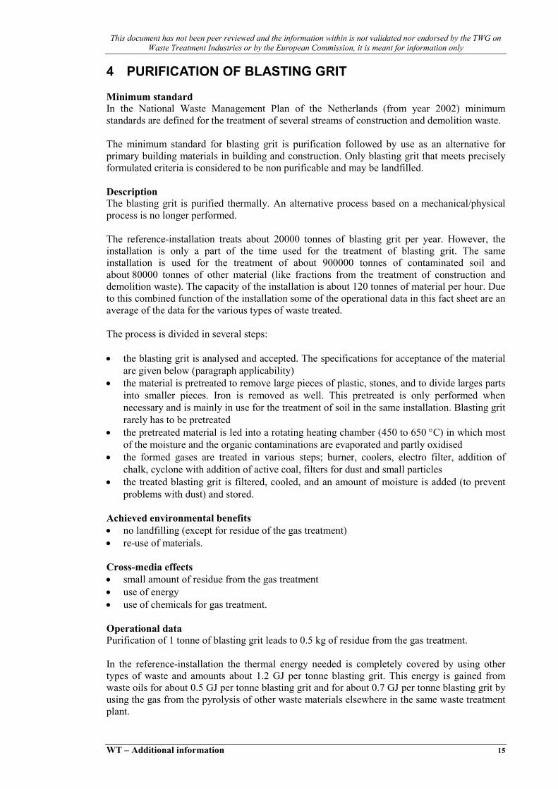
4 PURIFICATION OF BLASTING GRIT Minimum standard In the National Waste Management Plan of the Netherlands (from year 2002) minimum standards are defined for the treatment of several streams of construction and demolition waste. The minimum standard for blasting grit is purification followed by use as an alternative for primary building materials in building and construction. Only blasting grit that meets precisely formulated criteria is considered to be non purificable and may be landfilled. Description The blasting grit is purified thermally. An alternative process based on a mechanical/physical process is no longer performed. The reference-installation treats about 20000 tonnes of blasting grit per year. However, the installation is only a part of the time used for the treatment of blasting grit. The same installation is used for the treatment of about 900000 tonnes of contaminated soil and about 80000 tonnes of other material (like fractions from the treatment of construction and demolition waste). The capacity of the installation is about 120 tonnes of material per hour. Due to this combined function of the installation some of the operational data in this fact sheet are an average of the data for the various types of waste treated. The process is divided in several steps: • the blasting grit is analysed and accepted. The specifications for acceptance of the material
are given below (paragraph applicability) • the material is pretreated to remove large pieces of plastic, stones, and to divide larges parts
into smaller pieces. Iron is removed as well. This pretreated is only performed when necessary and is mainly in use for the treatment of soil in the same installation. Blasting grit rarely has to be pretreated
• the pretreated material is led into a rotating heating chamber (450 to 650 °C) in which most of the moisture and the organic contaminations are evaporated and partly oxidised
• the formed gases are treated in various steps; burner, coolers, electro filter, addition of chalk, cyclone with addition of active coal, filters for dust and small particles
• the treated blasting grit is filtered, cooled, and an amount of moisture is added (to prevent problems with dust) and stored.
Achieved environmental benefits • no landfilling (except for residue of the gas treatment) • re-use of materials. Cross-media effects • small amount of residue from the gas treatment • use of energy • use of chemicals for gas treatment. Operational data Purification of 1 tonne of blasting grit leads to 0.5 kg of residue from the gas treatment. In the reference-installation the thermal energy needed is completely covered by using other types of waste and amounts about 1.2 GJ per tonne blasting grit. This energy is gained from waste oils for about 0.5 GJ per tonne blasting grit and for about 0.7 GJ per tonne blasting grit by using the gas from the pyrolysis of other waste materials elsewhere in the same waste treatment plant.

This document has not been peer reviewed and the information within is not validated nor endorsed by the TWG on Waste Treatment Industries or by the European Commission, it is meant for information only
16 WT – Additional information
The emission of CxHy is about 4 kg per tonne treated blasting grit. A substantial part of these emissions originates from the waste fuels and gas from the pyrolysis which are used as a source for thermal energy. The gas treatment uses per tonne blasting grit about. • 0.27 m3 of water • 3.5 kg of Ca(OH)2 (aq) • 20 gram of active coal. The air used in the process is enriched with oxygen. No specific data are available on the amount used. The quality of the purified material is as shown in the table below.
Component Maximum concentration (mg per kg dry matter)
Oil residue 100 PAH 8
Aromatic compounds 1EOX 0.3
Phenols 0.25 CN 10
Table 4.1: Quality of purified material from thermal treatment [156, VROM, 2004]
For other components the removal from the gas-fraction is given below.
Component Percentage removed Dust >99.9 SO2 >98 HCl >99 Hg >99
Table 4.2: Removal efficiencies in the gas treatment [156, VROM, 2004]
The emissions of the treatment of 1 tonne of blasting grit are presented in Table 4.3.
Component Resulting emission (g/tonne) CO2 140000 CO 70
CxHy 3.2 PAH 0.05
Cyanides 1.1 PCDD/PCDF 50*E-9 (TEQ)
SO2 37 NOx 270 HCl 5.3 HF 0.5
Dust 11.3 Heavy metals 0.5
Hg 0.04 Cd + Tl 0.01
Table 4.3: Emissions to air of thermal treatment of blasting grit [156, VROM, 2004]

This document has not been peer reviewed and the information within is not validated nor endorsed by the TWG on Waste Treatment Industries or by the European Commission, it is meant for information only
WT – Additional information 17
Applicability The specifications of the treated blasting grit are presented in Table 4.4.
Component Maximum concentration (mg per kg dry matter)
CxHy 15000 CN 2000 EOX 200 HCH 110 Dioxins 30 (ug TEQ per kg dry matter)PCB 3.5 Organo-Sn 180 Hg 5 Organic sulphur 1000 Organic nitrogen 5000 – 450000
Table 4.4: Specifications for thermal treatment of blasting grit [156, VROM, 2004]
Economics No data available Driving force for implementation • landfilling is prohibited under Dutch law for grit that can be purified • formation of a material to use as an alternative for primary building materials in building
and construction. Example plants Afvalstoffen Terminal Moerdijk (ATM), Moerdijk, The Netherlands Reference literature [156, VROM, 2004]


This document has not been peer reviewed and the information within is not validated nor endorsed by the TWG on Waste Treatment Industries or by the European Commission, it is meant for information only
WT – Additional information 19
5 PURIFICATION CONTAMINATED SOIL Minimum standard In the National Waste Management Plan of the Netherlands (from year 2002) a minimum standard is defined for contaminated soil. The minimum standard for contaminated soil is purification followed by re-use as soil or as an alternative for primary building materials in building and construction. Only contaminated soil that cannot be purified to a reusable material may be landfilled. Description The contaminated soil is purified thermally or via a mechanical/physical process (depending on the type of contamination). This fact sheet deals with the thermal process which is suitable for soil that is contaminated with organic substances (oil, gasoline, PCBs) and volatile metals (like Hg). In the process organic contaminants are heated to a temperature high enough to volatilise and separate them from a contaminated solid medium. Air, combustion gas, or an inert gas is used as the transfer medium for the vaporized components. The systems for the thermal treatment of contaminated soil are differentiated from each other by the methods used to transfer heat to the contaminated soil, and by the flue-gas treatment system. Heat can be applied directly by radiation from a combustion flame and/or by convection from contact with the combustion gases. Systems employing this type of heat transfer are referred to as direct-contact or direct fired thermal desorption systems. An alternative way of heating the soil is using heat exchange. The latter is often referred to as indirect thermal desorption. The systems vary greatly in the amount of gas that has to be purified. The process in general is divided in several steps: • the contaminated soil is analysed. The specifications for acceptance are given below • the pretreatment to remove large pieces of plastic, stones, and to divide larges parts into
smaller pieces. Iron is removed as well. In some cases, especially those based on indirect heating, the soil is mixed with purified material in order to control the heat content of the soil (no more than about 1.8 MJ/kg), the moisture content and the concentration of some of the contaminants
• the pretreated material is led into a rotating heating chamber (450 to 650 °C for direct heating and 400 to 600 °C for indirect heating) in which most of the moisture and the organic contaminations are evaporated and partly oxidised. The temperature applies is always roughly a 100 °C above the boiling point of the main contaminants, which means that temperatures below about 525 °C are rare
• the formed gases are treated in various steps (with small differences between the several installations) like cyclone, burner, coolers, electro filter, addition of chalk, cyclone with addition of active coal, filters for dust and small particles. A part of the residue consists of ground-particles that can be recycled (added to the soil at the entrance of the purification process), thus minimizing the amount of material that has to be landfilled
• the treated contaminated soil is filtered, cooled, sometimes an amount of moisture is added (to prevent problems with dust) and stored.
Most of the installations do not exclusively treat contaminated soil but use the installation also for several other types of waste like fractions from the treatment of construction and demolition waste, blasting abrasive, filter medium originating from industrial processes, residue from the hydrodesulphurisation in the oil-industry, mining residue, etc. Most installations treat amounts of several hundreds of thousands tonnes per year.
This document has not been peer reviewed and the information within is not validated nor endorsed by the TWG on Waste Treatment Industries or by the European Commission, it is meant for information only
20 WT – Additional information
Achieved environmental benefits • no landfilling (except for residue of gas treatment) • re-use of materials. Cross-media effects • small amount of residue from the gas treatment • use of energy • use of chemicals for gas treatment. Operational data Purification of 1 tonne of contaminated soil leads to 0.2 to 0.5 kg of residue from the gas treatment. Depending on the type of residue this is landfilled or treated otherwise. The amount of mercury in the contaminated soil is a determining factor for the amount of residue (active coal). In one installation the thermal energy amounts to about 1.2 GJ/tonne contaminated soil (about 0.5 GJ per tonne arising from waste oils and about 0.7 GJ per tonne by using the gas from the pyrolysis of other waste materials elsewhere in the same waste treatment plant). Another installation uses about 1.7 GJ per tonne contaminated soil, using both electricity (0.2 GJ/tonne) and gas (1.5 GJ/tonne) as an energy-source. The gas treatment uses per tonne contaminated soil about: • 0.27 m3 to 0.4 m3 of water (for cooling and avoiding problems with the spreading of small
particles. Mainly treated waste water from within the installations is used • 3.5 kg of Ca(OH)2 (aq) to 11 kg of CaO (s), strongly depending on the amounts of sulphur
and chlorine in the soil • 20 gram to 1 kg of active coal, strongly depending on the amounts of Hg and EOX in the
soil. The quality of the purified material is as shown in the table below.
Component Maximum concentration(mg per kg dry matter)
Oil residue 100 PAH 8 Aromatic compounds 1 EOX 0.3 Phenols 0.25 CN 10
Table 5.1: Quality of purified material from thermal treatment [156, VROM, 2004]
For other components the removal from the gas-fraction is given below.
Component Percentage removed Dust >99.9 SO2 >98 HCl >99 Hg >99
Table 5.2: Removal efficiencies in the gas treatment [156, VROM, 2004]
This document has not been peer reviewed and the information within is not validated nor endorsed by the TWG on Waste Treatment Industries or by the European Commission, it is meant for information only
WT – Additional information 21
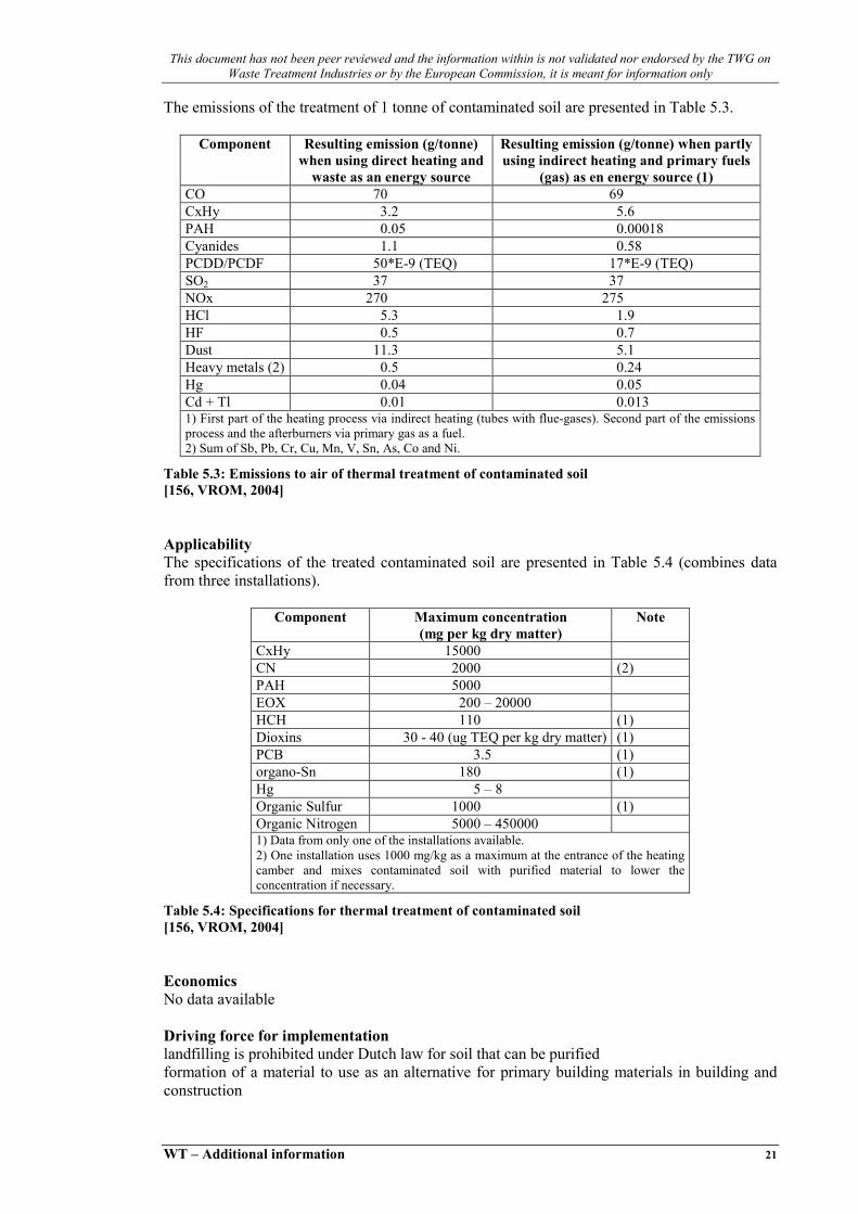
The emissions of the treatment of 1 tonne of contaminated soil are presented in Table 5.3.
Component Resulting emission (g/tonne) when using direct heating and
waste as an energy source
Resulting emission (g/tonne) when partly using indirect heating and primary fuels
(gas) as en energy source (1) CO 70 69 CxHy 3.2 5.6 PAH 0.05 0.00018 Cyanides 1.1 0.58 PCDD/PCDF 50*E-9 (TEQ) 17*E-9 (TEQ) SO2 37 37 NOx 270 275 HCl 5.3 1.9 HF 0.5 0.7 Dust 11.3 5.1 Heavy metals (2) 0.5 0.24 Hg 0.04 0.05 Cd + Tl 0.01 0.013 1) First part of the heating process via indirect heating (tubes with flue-gases). Second part of the emissions process and the afterburners via primary gas as a fuel. 2) Sum of Sb, Pb, Cr, Cu, Mn, V, Sn, As, Co and Ni.
Table 5.3: Emissions to air of thermal treatment of contaminated soil [156, VROM, 2004]
Applicability The specifications of the treated contaminated soil are presented in Table 5.4 (combines data from three installations).
Component Maximum concentration (mg per kg dry matter)
Note
CxHy 15000 CN 2000 (2) PAH 5000 EOX 200 – 20000 HCH 110 (1) Dioxins 30 - 40 (ug TEQ per kg dry matter) (1) PCB 3.5 (1) organo-Sn 180 (1) Hg 5 – 8 Organic Sulfur 1000 (1) Organic Nitrogen 5000 – 450000 1) Data from only one of the installations available. 2) One installation uses 1000 mg/kg as a maximum at the entrance of the heating camber and mixes contaminated soil with purified material to lower the concentration if necessary.
Table 5.4: Specifications for thermal treatment of contaminated soil [156, VROM, 2004]
Economics No data available Driving force for implementation landfilling is prohibited under Dutch law for soil that can be purified formation of a material to use as an alternative for primary building materials in building and construction

This document has not been peer reviewed and the information within is not validated nor endorsed by the TWG on Waste Treatment Industries or by the European Commission, it is meant for information only
22 WT – Additional information
Example plants Afvalstoffen Terminal Moerdijk (ATM), Moerdijk, The Netherlands Sita Remidiation B.V., Torontostraat 2, Rotterdam, The Netherlands Reference literature [156, VROM, 2004]

This document has not been peer reviewed and the information within is not validated nor endorsed by the TWG on Waste Treatment Industries or by the European Commission, it is meant for information only
WT – Additional information 23
6 THERMAL TREATMENT OF TAR-CONTAINING ASPHALT Minimum standard In the National Waste Management Plan of the Netherlands (from year 2002) minimum standards are defined for the treatment of several streams of construction and demolition waste. The minimum standard for tar-containing asphalt is recycling preceded by thermal treatment in which the PAHs are destroyed. The secondary building material must meet the standards of the Building Material Decree. Tar-containing asphalt is defined as asphalt with a PAH-content of more than 75 mg/kg PAH 1. It is not allow to apply untreated tar-containing asphalt. Mixing of tar-containing asphalt and asphalt that does not contain tar must be prevented. Description In the thermal installation tar-containing asphalt is cleaned to a product that can be re-used or to a material that can be recycled. After the treatment the product meets the standards of the Building Material Decree. Tar-containing asphalt can be processed together with other wastes that has to be cleaned to a building material (except soil), such as rubble and gravel. Mixing can only take place if treatment of the separate waste streams would lead to the same quality, in accordance with the Building Material Decree. The cleaning process consists of a pretreatment and the actual thermal cleaning (rotating oven) with a flue-gas treatment. By heating the material in the oven the contaminants evaporate. In the incinerator of the flue-gas treatment (after-burner) the contaminants are destroyed. Percolation water from the stored waste materials and rainwater are purified. The separated sludge from this water treatment goes to the thermal treatment installation. The purified effluent is used as process water, which means that normally no effluent is discharged.
Pre-treatment Rotary oven Flue-gas treatment
Metal/plastic/wood335 tonnes
Flue-gas cleaning residue10 tonnes
Tar-containing asphalt e.o.
220000 tonnes
Water> 90000 m3
NaOH 360 m3
NH4OH 120 m3
activated carbon 16 m3 *)lime 20 tonnes
Clean product200000 tonnes
Clean gas
*) Including waste water treatment
Figure 6.1: process of thermal treatmenr of tar-containing asphalt [156, VROM, 2004]
1 Here PAH is defined the total of 10 PAHs: anthracene, benz(a)anthracene, benzo(k)fluoranthene, benzo(a)pyrene, chrisene, phenanthrene, fluoranthene, indeno (1,2,3-cd) pyrene, naphtalene, benzo(ghi)perilene

This document has not been peer reviewed and the information within is not validated nor endorsed by the TWG on Waste Treatment Industries or by the European Commission, it is meant for information only
24 WT – Additional information
In the pretreatment of the thermal treatment process the material is broken by means of a shredder and waste, such as plastic, wood and rubble, and iron is removed by means of a sieve and a magnetic separator. Than the material is lead into the rotary oven, where the organic contaminants are removed by heating (400 to 600 °C). At the end of the rotary oven the material is cooled by effluent of the waste water treatment. The contaminated flue-gas is treated by means of dust removal in cyclones, incineration (after-burning) with energy recovery by means of a heat exchanger, dust filtration, cleaning in a reactor filter and wet scrubber, to remove the contaminants. The clean gas is emitted. The separated dust is returned to the oven. Used carbon and lime are sent for disposal as flue-gas residues. The energy content of the flue-gas is partly recovered by means of a heat exchanger and used for process heating. For the required water in the flue-gas treatment effluent from the waste water is used. The process parameters in the oven and the after-burner, such as temperature, oxygen content and dwell time, are adjusted to the contaminants in the waste. Achieved environmental benefits Due to the thermal treatment process the tar-containing asphalts can be re-used as a secondary building material. The organic contaminants, especially PAHs, are destroyed which prevents the diffusion of toxic compounds in the environment. Cross-media effects Relevant cross-media effects are: • consumption of energy • consumption of chemicals • emissions to air • production of flue-gas residue. Operational data Consumption of energyEnergy is particularly required for the burners of the thermal installation and amounts to 31 TJ per year at an input of 220 ktonnes a year, thus c. 140 MJ/tonne waste. This concerns an average energy consumption of treatment of several wastes, especially soil and tar-containing asphalt. Because the energy consumption depends on the water content and the caloric value of the material, the average consumption for tar-containing asphalt (dryer and more combustible contaminants) is lower. Electricity is required for the shredder and the compressors. The electricity use amounts to 6.7 TJ per year at an input of 220 ktonnes a year, i.e c. 30 MJ/tonne waste. Consumption of auxiliary materialsIn the flue-gas treatment chemicals are used: activated carbon, lime, sodium hydroxide and NH4OH. In the waste water treatment activated carbon, poly-electrolyte, FeCl3, sand and gravel are used. For the cooling of the cleaned waste from the oven and for quenching and scrubbing the flue-gas, water is required.

This document has not been peer reviewed and the information within is not validated nor endorsed by the TWG on Waste Treatment Industries or by the European Commission, it is meant for information only
WT – Additional information 25
In Table 6.1 the amounts of auxiliary materials in the thermal treatment process are presented.
Material Function Consumption Unit Activated carbon FGT1)/WWT2) 16 m3
Lime FGT1) removal of SO2 e.o. 20 tonnes NaOH FGT1) pH-adjustment 360 m3
NH4OH-solution FGT1) NOx-removal 120 m3
Tap water 3) Divers 60000 m3
1) FGT: flue-gas treatment 2) WWT: waste water treatment 3) Excluding water for cooling in the thermal treatment, for which effluent from the waste water treatment is used.
Table 6.1: Yearly consumption of auxiliary materials in the thermal treatment of tar-containing asphalt and other waste at an input of 220 ktonnes [156, VROM, 2004]
The water consumption in the thermal treatment of soil amounts to 0.3-0.4 m3/tonne soil. An input of 220 ktonnes of tar-containing asphalt will use at least 90.000 m3 water. In the example plant effluent from the waste water treatment is used, which means savings of the primary input of water. Emissions to airStorage of thermal treatment of waste asphalt and similar waste can create emissions: • emissions from the flue-gas treatment, such as CO2, CO, CxHy and NOx
• odour • emissions of dust through dispersion. The high concentration of bitumen in the tar-containing asphalt causes a high load of organic contaminants in the after-burner. To avoid high emissions of CO and CxHy an adjustment to the flue-gas treatment installation is needed whereby part of the flue-gas is refluxed to the oven (after the cyclone). This prevents an overload of the after-burner and reduces the energy consumption of the oven due to the recovery of the energy content of a the refluxed flue-gas. In the oven thermal NOx is created. To reduce the emission of NOx a NH3 solution must be added: selective non-catalytic reduction (SNCR-DeNOx). The treatment of tar-containing asphalt can create odour related to emissions of hydrocarbons. Through dispersion dust emissions can occur. To reduce the dust emissions several measures are taken, such as operating the processes in enclosed installations or buildings and spraying installations at the product storage.

This document has not been peer reviewed and the information within is not validated nor endorsed by the TWG on Waste Treatment Industries or by the European Commission, it is meant for information only
26 WT – Additional information
In Table 6.2 emissions to the air from the thermal treatment of tar-containing asphalt are presented.
Parameter Unit Standard 1) Emission 2) Load (g/tonne)4)
Flow Nm3/h 25700 CO mg/Nm3 50 11.6 12 SO2 mg/Nm3 40 15.8 16 NOx mg/Nm3 70 176 3) 180 CxHy mg/Nm3 10 3.0 3.1 HCl mg/Nm3 10 0.13 0.13 HCN mg/Nm3 - <0.1 <0.1 HF mg/Nm3 1 0.3 0.3 PM mg/Nm3 5 3.3 3.4 PAH mg/Nm3 - <0.1 <0.0001 Cd mg/Nm3 0.05 <0.01 <0.01 Hg mg/Nm3 0.05 0.013 0.013 Heavy metals mg/Nm3 1 0.013 0.013 PCDD/PCDF ng TEQ/Nm3 0.1 <0.01 <1.0E-08 1) Emission standards in accordance with the Decree Air Emissions Waste Incineration (BLA: Besluit lichtemissies afvalverbranding); the standards in the Waste Incineration Decree in preparation (BVA: Besluit verbranden afvalstoffen (BVA) are similar; 2) Based on measurements of hourly averages 3) With addition of NH3-solution in the after-burner 4) Loads are based on a throughput of 25 tonnes/hour
Table 6.2: Emissions from treatment of tar-containing asphalt in a thermal cleaning installation [156, VROM, 2004]
The table shows that the emissions meet the standards of the Decree Air Emissions Waste Incineration, except for NOx. NOx is mainly created in the after-burner (thermal NOx). By creating optimal conditions in the appliance of the SNCR-DeNOx (dosage of NH3-solution) a further reduction can be obtained. Measurements show that emissions of odour from the treatment of tar-containing asphalt range from 34 to 76 * 106 odour units per hour. Emissions to waterDue to the recycling of the effluent from the waste water treatment in the production process, no discharge takes place. Solid wasteThe thermal treatment process creates flue-gas residue which consists of used adsorbent (carbon and lime) from the reaction filter. In the pretreatment metal, wood and plastic are separated. At an input of 220 ktonnes a year the following amounts of solid waste are produced: • 10 tonnes adsorbent from reactor filter (flue-gas treatment) • 335 tonnes of separated metal/wood/plastic. Applicability The thermal treatment is applicable to mineral, stony waste, such as asphalt, rubble and gravel, that is contaminated with organic substances. The thermal treatment is aimed at the removal and destruction of organic substances such as PAHs and mineral oil. The treatment is not suitable for removal of compounds that do not evaporate at the applied temperatures in the oven, such as heavy metals (except Hg) and asbestos.

This document has not been peer reviewed and the information within is not validated nor endorsed by the TWG on Waste Treatment Industries or by the European Commission, it is meant for information only
WT – Additional information 27
The maximum concentrations of contaminants in the material to be treated in the thermal installation (see Table 6.3) are based on the standards for the building material to be produced (Building Material Decree) and the emission standards (Decree Air Emissions Waste Incineration). For most organic substances and for mercury these concentrations can be obtained by mixing. For dioxins/furans and asbestos the concentrations are acceptance criteria: waste streams with higher concentrations cannot be accepted for treatment and mixed with streams with lower concentrations.
Component Maximum concentration (mg/kg DM) Hg 8 EOCl/EOX 20000 PAH 5000 CxHy 15000 PCDD/PCDF 40000 ng TEQ/kg Asbestos 100
Table 6.3: Maximum concentrations in tar-containing asphalt and similar waste (to be cleaned to building material not being soil) for input in the thermal treatment installation [156, VROM, 2004]
The capacity of the example installation is c. 30 tonnes/hour, which means a maximum yearly throughput of 220 ktonnes/year. Economics No data available Driving force for implementation • prohibition to apply untreated tar-containing asphalt as building material • production of a secondary building material • saving of costs for disposal. Example plants Sita Remediation, Botlek Reference literature [156, VROM, 2004]


This document has not been peer reviewed and the information within is not validated nor endorsed by the TWG on Waste Treatment Industries or by the European Commission, it is meant for information only
WT – Additional information 29
7 DRYING OF SEWAGE SLUDGE Minimum standard In the National Waste Management Plan of the Netherlands (from year 2002) a minimum standard is defined for the treatment of sewage sludge. The minimum standard for sludge from urban and industrial waste water treatment installations is thermal treatment (with drying as a pretreatment). This means that incineration in different types of installations, possibly in combination with biological or thermal drying as a pretreatment, is allowed. Wet oxidation and pyrolysis/melting is not allowed, based on the present available data. Wet oxidation requires a large amount of chemicals (to clean the reactor regularly), does not use the energy-content of the waste, and results in a residue that has to be landfilled. Application of sewage sludge as an auxiliary agent in the treatment of fly ash from waste incineration into Hydrostab is allowed. In this fact sheet the different techniques for drying are described. The incineration of sewage sludge is not dealt with here, because this is covered in the Bref Waste Incineration. Description In the thermal drying process the mechanical dewatered sewage sludge is dried by means of conduction drying (no direct contact between heating medium and waste) in fluidised bed dryers. The heating medium is steam. The water evaporates from the sludge, together with volatile compounds, such as ammonia and odour causing compounds. The resulting vapour is cooled and water vapour is condensed. The non-condensable vapours are exhausted and treated in a scrubber to remove ammonia and a biofilter, in order to prevent odour. The condensate and the effluent from the scrubber are purified in a waste water treatment and discharged. In the biological drying process the sewage sludge is mixed with auxiliary material (wood chips) and compost. These substances function as carrier material, provide graft material, an airy structure an a higher carbon/nitrogen rate, contribute to the energy production and absorb part of the water from the sludge. The biological sludge dryer is a tunnel compost system. The sludge is placed in an enclosed horizontal reactor (tunnel). Air is blown in at the bottom side and provides the required oxygen for the biological process. Part of the organic substance is degraded, which provides the required heat for the drying process. The inserted air raises in temperature and becomes saturated with water vapour. In this way the sludge is dried. After this pre-composting the material is sieved to separate the compost from the auxiliary material. The compost undergoes a further composting process, in which it is aerated during 14 days in order to degrade the poor degradable organic substances. To prevent odour the exhausted air is treated in a scrubber to remove ammonia and a biofilter. The effluent from the scrubber is purified in a waste water treatment and discharged.

This document has not been peer reviewed and the information within is not validated nor endorsed by the TWG on Waste Treatment Industries or by the European Commission, it is meant for information only
30 WT – Additional information
Thermal drying
Condensing vapour
Condensate
Sewage sludge
Non-condensable vapour
Water treatment
Gas treatment(scrubber, biofilter)
Effluent scrubber
Dried sludge90% dry matter
Effluent
Use as secondary fuel
Clean gas
Figure 7.1: Thermal drying of sewage sludge [156, VROM, 2004]
Biologicaldrying
Sieving
Composting
Sewage sludge
Vapour
Water treatment
Gas treatment(scrubber, biofilter)
Effluent scrubber
Dried sludge70% dry matter
Effluent
Use as secondary fuel
Clean gas
Wood chips,air
Figure 7.2: Biological drying of sewage sludge [156, VROM, 2004]
Achieved environmental benefits The environmental benefit of thermal or biological drying of sewage sludge as a pretreatment is the possibility of recycling the sludge as a secondary fuel for electricity production or in a cement kiln. The benefits in comparison with landfilling the sewage sludge are the recovery of energy and the prevention of landfilling and the released emissions of methane. In comparison with incineration of the sewage sludge in a waste incinerator the energy recovery is higher as well.
The environmental benefit in comparison to recycling the sewage sludge as a fertiliser in the agricultural sector, is the prevention of the diffusion of toxic substances, such as heavy metals, in the environment (water and soil) and in the crops. For this application standards are set for concentrations of heavy metals, in the Quality and Use of Other Organic Fertilisers Decree (from year 1998): Cd <1.25 mg/kg, Cr <75 mg/kg, Cu <75 mg/kg, Hg <0.75 mg/kg, Ni <30 mg/kg, Pb <100 mg/kg, Zn <300 mg/kg, As <15 mg/kg (concentrations in mg/kg dry matter). Sewage sludge from urban waste water treatment installations does not meet this standards. Some industrial sewage sludge, such as sludges from the food industry, does meet the standards.

This document has not been peer reviewed and the information within is not validated nor endorsed by the TWG on Waste Treatment Industries or by the European Commission, it is meant for information only
WT – Additional information 31
Thermal drying results in a higher energy recovery than biological drying. This is due to the fact that the energy consumption of thermal drying is lower than the energy consumption of biological drying (provided by the organic material in the sewage sludge) and the product of the thermal drying has a higher dry material content. This results in a higher caloric value of the secondary fuel. Cross-media effects Through the drying of the sludge, especially biological drying, emissions to the air occur, among which odour compounds. These are treated by means of a scrubber and a biofilter. The tunnel compost system is a enclosed installation through which the emissions can be adequately controlled. Emissions to water occur through the effluent of the scrubber and the condensate of the thermal dryer. Both waste water streams are purified and discharged. Operational data In the process of thermal drying the mechanical dewatered sludge (dry matter content of c. 25 %) is dried to a dry matter content of more than 90 %. The energy consumption of the thermal drying is 2.4 GJ thermal energy and 8.7 kWh electricity per tonne sludge. The caloric value of the dry sludge is c. 12 MJ/kg. In the biological drying process the mechanical dewatered sludge (dry matter content of c. 25 %) is dried to a dry matter content of c. 70 %. The consumption of electricity of the biological drying installation is 35 kWh. The drying heat is provided by the degradation of part of the organic substance of the sludge. This results in a lower caloric value of the product. The caloric value for the dry sludge from the biological drying process is c. 6 MJ/kg. In Table 7.1 the consumption of auxiliary materials in the thermal sludge drying process are presented.
Material Consumption (litre per tonne sludge)
Tap water 35 Sulphuric acid (90 %) 0.05 Liquid nitrogen 0.15 Anti-scaling 0.00044 Oxygen scavenger 0.0057
Table 7.1: Consumption of auxiliary materials in the thermal sludge drying process [156, VROM, 2004]
A biological sludge drying installation consumes c. 50 kg wood chips per tonne sludge. Table 7.2 present estimated emissions to air from the thermal and the biological drying installation. In the scrubber the ammonia concentration is reduced to a maximum of 30 ppm. For the biofilter a removal efficiency of 95 % is assumed. The emissions from the biological drying process are higher because the flowrate is higher due to the air supply.
Component Concentration before biofilter
(mg/Nm3)
Concentration after biofilter
(mg/Nm3)
Emission thermal drying
(g/tonne sludge)
Emission biological drying
(g/tonne sludge) NH3 30 1.5 1.1 7.1 CxHy 50 2.5 1.8 11.9
Table 7.2: Emissions to air from the thermal and the biological drying installation [156, VROM, 2004]

This document has not been peer reviewed and the information within is not validated nor endorsed by the TWG on Waste Treatment Industries or by the European Commission, it is meant for information only
32 WT – Additional information
Table 7.3 presents emissions to water from the effluent of the scrubber and the condensate of the thermal drying process. The removal efficiencies are based on a representative waste water treatment. The emissions of the biological drying process are caused by the effluent of the scrubber, the emissions of the thermal drying process are mainly caused by the condensate. It is expected that in the biological drying process a lower amount of metals come along in the vapour then in the case of thermal drying. Data on the emissions of heavy metals are not available.
Component Load to waste water treatment thermal drying (g/tonne sludge)
Load to waste water treatment biological drying (g/tonne sludge)
Removal efficiency
(%)
Emissions thermal drying (g/tonne sludge)
Emissions biological drying(g/tonne sludge)
Suspended solids 35 396 90 3.5 39.6 N-total (Kjeldahl)
231 1386 89 25.4 153
BOD 371 139 97 11.1 4.2 COD 462 1267 90 46.2 127
(mg/tonne sludge) (mg/tonne sludge) As 6.0 - 1) 80 1.2 - 1)
Cd 0.98 - 1) 72 0.3 – 0.4 - 1)
Cr 18.2 - 1) 89 2 – 4 - 1) Cu 200 - 1) 92 16 - 1) Hg 0.7 - 1) 91 0.06 – 0.09 - 1) Ni 14.7 - 1) 46 7.9 - 1) Pb 87.5 - 1) 91 7.9 - 1) Zn 448 - 1) 75 112 - 1) 1) data not available
Table 7.3: Emissions to water from the thermal and the biological drying installation [156, VROM, 2004]
Applicability The drying techniques are applicable to sewage sludge from urban and industrial waste water treatment installations. The capacity of the example installation for thermal drying is 114 ktonnes sludge per year. The capacity of the example installation for biological drying is 84 ktonnes sludge per year. Economics No data available Driving force for implementation Economical value of secondary fuels Policy to restrict and finally ban the landfilling of sewage sludge Minimum standard for sewage sludge as defined in the National waste Management Plan Example plants Thermal drying: Sludge drying installation Beverwijk Biological drying: GMD Tiel. Reference literature [156, VROM, 2004]
This document has not been peer reviewed and the information within is not validated nor endorsed by the TWG on Waste Treatment Industries or by the European Commission, it is meant for information only
WT – Additional information 33
8 BIOLOGICAL TREATMENT OF SEPARATED BIOWASTE Reference: [133, UBA, 2003]
8.1 Composting Purpose Produce compost from separately collected biowaste from households and industry. Use the compost as fertilizer and soil conditioner. Techniques Composting includes the bacterial decomposition of organic material under aerobic conditions. Organic material mainly from plants should be converted into humus. The biological process induces the heating of the material which causes the elimination of pathogenic micro-organisms. Feed and product streams Separated organic waste from households (biowaste) and green waste from gardens and parks are the main product streams entering composting plants. For aeration it is important that the material is sufficiently structured and not too wet. Waste from industries like the food industry is only suited for composting after mixing with structured material. The separate collection of the biowaste is crucial to ensure pureness of the material. Experiences in different countries have shown that compost produced from mixed household waste is too much contaminated with hazardous substances like heavy metals. The processes which take place in a composting plant are: • delivery of waste • mechanical treatment (pretreatment) • intensive aerobic treatment/decomposition • extensive aerobic treatment (maturing process). During these processes a lot of waste gas is produced. It is necessary to collect the waste gas that is generated at delivery and mechanical treatment. Also the gas produced by the aeration of the aerobic process has to be collected. The collected waste gas has to be cleaned in gas treatment facilities before it is emitted into the atmosphere. Facilities shall be constructed and operated so that the entry of sewage water into the soil is prevented. The condensed water vapours arising from ventilation of the windrows and the accumulated seepage water shall only be used in open composting to moisten the compost if odour irritations may be avoided and the process of hygienisation (sanitation) is not affected. 2
The main product of the process is the compost which can be used for agricultural and horticultural purposes. This compost is usable as a light fertilizer. Very important for the use of compost are its soil conditioning properties. Process description Pretreatment:The first step after the delivery of the biowaste is the pretreatment. The pretreatment includes a separation of wrongly sorted material (contraries) and oversized pieces. A drum sieve may be used for opening bags and homogenising the material. After this a lot of different facilities may be used to separate materials like metals, plastics or larger pieces of inerts. Separation can be done by size (sieve), density, magnetism or electric properties.
2 German Technical Instructions on Air Quality Control, from 30th July 2002

This document has not been peer reviewed and the information within is not validated nor endorsed by the TWG on Waste Treatment Industries or by the European Commission, it is meant for information only
34 WT – Additional information
The separation of contraries is often done in manual work. In this case it is necessary that the workplace is situated in a closed cabin. For the safety of the employee it is important that the cabin has got a ventilation which guarantee that the air at the workplace is comparable to external air. A further process of size reduction then follows which creates a more homogenous material in order to aid the composting process. For size reduction screw-cutting, milling, drumming, pulping or shredding machines can be used. Composting:The process of aerobic digestion/decomposition produces a lot of heat. Temperatures of 70 °C and more can be reached in windrows. The used technology ranges from very simple windrow composting without forced aeration over windrows within buildings (closed composting, in-vessel) with forced air systems to composting in containers or boxes with process controlling and forced air systems. The techniques can be classified according to their properties: • open or closed composting • with or without forced aeration • different process techniques like windrow-, container-, box- or tunnel-composting. Open air windrow composting is the simplest technique. These plants in general work without forced aeration and waste gas collecting. Techniques with forced air systems are mostly associated with the collecting and treatment of waste gas. Very common is waste gas treatment by means of combined scrubber and bio filter systems. Users Composting plants usually are operated by communal or private companies who collect bio or garden waste from households. By collecting biowaste separately and processing it into compost a large quantity of municipal solid waste from households can be recycled. Thus, composting can help to greatly reduce the amount of waste for incineration or disposal.
8.2 Anaerobic digestion Purpose Anaerobic digestion of separately collected biowaste or industrial waste is a way to produce fertiliser or soil conditioner and energy-rich biogas at the same time. Techniques Anaerobic digestion involves the bacterial decomposition of organic material in the (relative) absence of oxygen. The products of anaerobic digestion are a digestate similar to liquid manure and a biogas containing mainly methane and carbon dioxide. Feed and product streams In addition to biowaste from households organic waste from the food industry or manure can be processed in anaerobic digestion plants. By contrast to composting, anaerobic digestion can be used to treat wet material with less structure. However, materials with a high lignin content such as wood are not suitable due to the fact that lignin cannot be degraded by anaerobic micro-organisms. It is important to note that the mixing of household waste with waste from agriculture may improve both the environmental and the economic benefits and has been adopted in a number of plants. The co-digestion with slurry and manure is often practised in small-scale farm-based plants.
This document has not been peer reviewed and the information within is not validated nor endorsed by the TWG on Waste Treatment Industries or by the European Commission, it is meant for information only
WT – Additional information 35
The processes which take place in an anaerobic digestion plant are: • delivery of waste • mechanical treatment (pretreatment) • anaerobic digestion • after treatment (maturing process). In the anaerobic reactor the organic matter is converted into biogas and digestate. The biogas consists mainly of methane and carbon dioxide. The proportions of the combustible gas methane and the carbon dioxide ranges from 55 to 75 % methane and 25 to 45 % CO2.
The average output of biogas is 100 m3 per tonne biowaste. The biogas has an energy content of about 5.0 – 7.0 kWh/m3. This means it is possible to gain 500 – 700 kWh energy from one tonne of biowaste. The energy of the biogas can be used to produce electricity and/or heat. The aim for the optimal use of the biogas should be combined heat and power. Most anaerobic digestion plants in Germany produce electricity in engines. The waste-heat of the engine can be used for heating buildings or for technical processes like drying biomass etc. It is also possible to use the biogas as an alternative fuel in cars or commercial vehicles. Before using the gas in engines it is necessary to remove components like hydrogen sulphide (H2S). The contamination of the biogas with H2S ranges from 200 to 4000 ppm. The combustion of gas with a high H2S-content can cause corrosion of parts of the engine. The semi-solid residue, referred to as digestate, is usually treated further by composting. The composted digestate may be used for agricultural/horticultural purposes. It is also possible to use the digestate directly on farmland like liquid manure. The key properties of the digestate from biowaste are its high content of organic matter and, compared to compost, its high content of nutrients such as nitrogen and phosphorus. The system needs to have a balanced feed and constant conditions to maximise methane production. The plants typically measure TOC, COD, N, P and Cl in inlet and outlet flows, in order to balance feeds and to ensure good methane production. Waste gas which has to be treated occurs in anaerobic digestion plants especially at the delivery of the biowaste and in the mechanical pretreatment. After the anaerobic process at the beginning of the maturing process also a lot of waste gas is generated. Facilities shall be constructed and operated so that the entry of sewage water into the soil is prevented. Processing water is to be retained and put to internal use. The condensed water vapours arising from ventilation of the windrows (maturing process) and the accumulated seepage water shall only be used in open composting to moisten the compost if odour irritations may be avoided. 3
Process description Plants for anaerobic digestion (AD) generally dispose of the following treatment steps.
3 German Technical Instructions on Air Quality Control, from 30th July 2002

This document has not been peer reviewed and the information within is not validated nor endorsed by the TWG on Waste Treatment Industries or by the European Commission, it is meant for information only
36 WT – Additional information
Pretreatment:The source-separated biowaste however requires further separation to remove wrongly sorted material (contraries), such as plastics, metals and oversized components (note that this is a consequence of the technical features of the AD process which requires coarse inerts to be removed). Separation can be carried out under wet or dry conditions. The separation can be done by size (sieve), density, magnetism or electric properties. The separation of contraries is often done in manual work. In this case it is necessary that the workplace is situated in a closed cabin. For the safety of the employee it is important that the cabin has got a ventilation which guarantee that the air at the workplace is comparable to external air. Another process of size reduction that follows makes the material more homogenous, which aids fermentation and facilitates processing. Screw-cutting, milling, drumming, pulping or shredding machines can be used for size reduction. Digestion:The anaerobic degradation of organic matter can be divided into different phases. In the most digestion plants these phases take place at the same time in the same reactor (exceptions are two or more step processes). Theses phases are: • hydrolysis • acid phase • acetic acid phase • methane phase. There is a number of different techniques used to carry out anaerobic digestion. They are usually divided into: • mesophilic or thermophilic digestion (thermophilic plants operate at around 50-60 °C,
mesophilic at around 35 °C) • dry or wet digestion (dry digestion needs around 25 % dry matter, wet digestion
around 10 % dry matter) • one or two step process (in the one step process all phases of the anaerobic digestion take
place in one reactor, in two or more step processes the hydrolysis and acidic phase are separated from the methane phase).
Users Large anaerobic digestion plants are often operated by communal or private companies for the treatment of separated biowaste from households or industries and in order to produce both fertilisers and soil conditioners and biogas which can be transformed in electric or thermal energy. Small scale anaerobic digestion plants are often situated on farms. These plants use a mixture of agricultural waste, biowaste from households and biomass from plants. Thereby making use of the possibility to treat their manure and to produce energy from biogas at the same time. With biowaste and residues from plants the farmers are thus able to augment their earnings from biogas production.
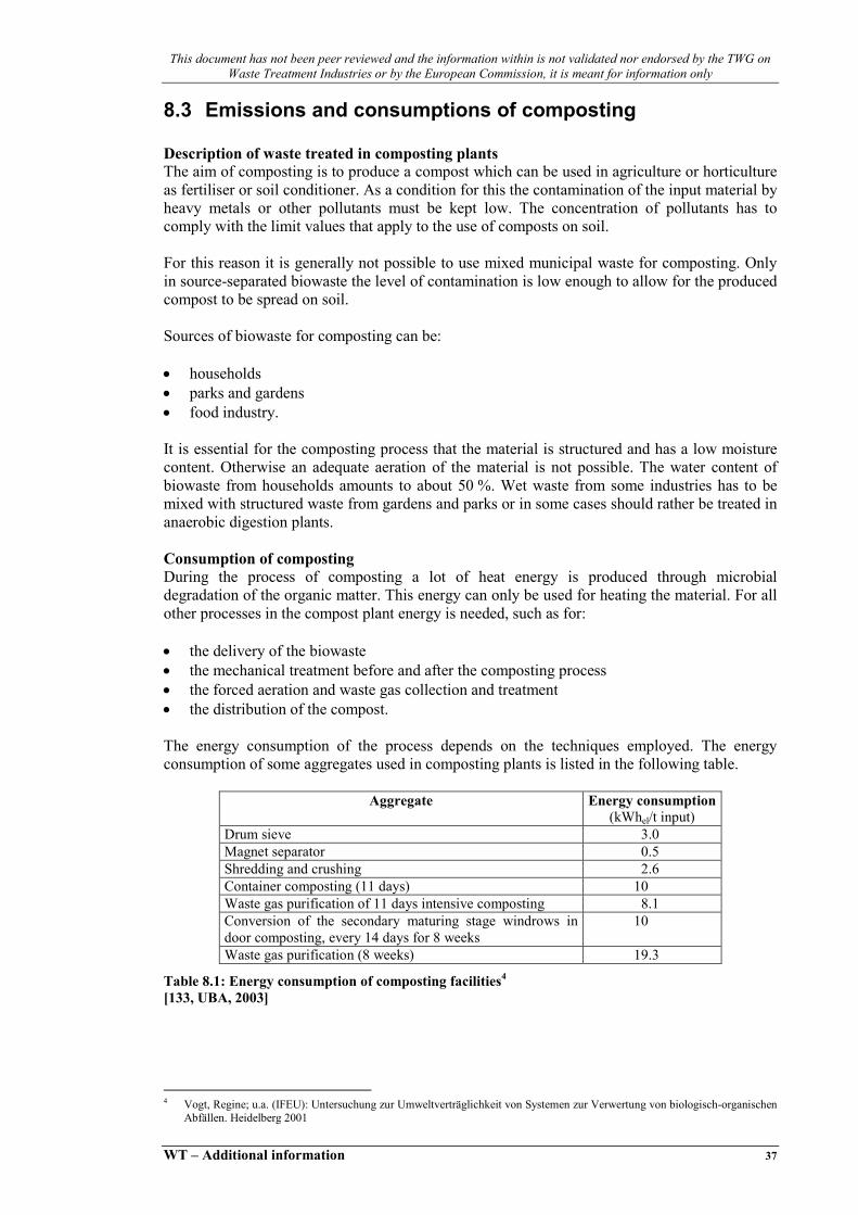
This document has not been peer reviewed and the information within is not validated nor endorsed by the TWG on Waste Treatment Industries or by the European Commission, it is meant for information only
WT – Additional information 37
8.3 Emissions and consumptions of composting Description of waste treated in composting plants The aim of composting is to produce a compost which can be used in agriculture or horticulture as fertiliser or soil conditioner. As a condition for this the contamination of the input material by heavy metals or other pollutants must be kept low. The concentration of pollutants has to comply with the limit values that apply to the use of composts on soil. For this reason it is generally not possible to use mixed municipal waste for composting. Only in source-separated biowaste the level of contamination is low enough to allow for the produced compost to be spread on soil. Sources of biowaste for composting can be: • households • parks and gardens • food industry. It is essential for the composting process that the material is structured and has a low moisture content. Otherwise an adequate aeration of the material is not possible. The water content of biowaste from households amounts to about 50 %. Wet waste from some industries has to be mixed with structured waste from gardens and parks or in some cases should rather be treated in anaerobic digestion plants. Consumption of composting During the process of composting a lot of heat energy is produced through microbial degradation of the organic matter. This energy can only be used for heating the material. For all other processes in the compost plant energy is needed, such as for: • the delivery of the biowaste • the mechanical treatment before and after the composting process • the forced aeration and waste gas collection and treatment • the distribution of the compost. The energy consumption of the process depends on the techniques employed. The energy consumption of some aggregates used in composting plants is listed in the following table.
Aggregate Energy consumption(kWhel/t input)
Drum sieve 3.0 Magnet separator 0.5 Shredding and crushing 2.6 Container composting (11 days) 10 Waste gas purification of 11 days intensive composting 8.1 Conversion of the secondary maturing stage windrows in door composting, every 14 days for 8 weeks
10
Waste gas purification (8 weeks) 19.3
Table 8.1: Energy consumption of composting facilities4
[133, UBA, 2003]
4 Vogt, Regine; u.a. (IFEU): Untersuchung zur Umweltverträglichkeit von Systemen zur Verwertung von biologisch-organischen Abfällen. Heidelberg 2001
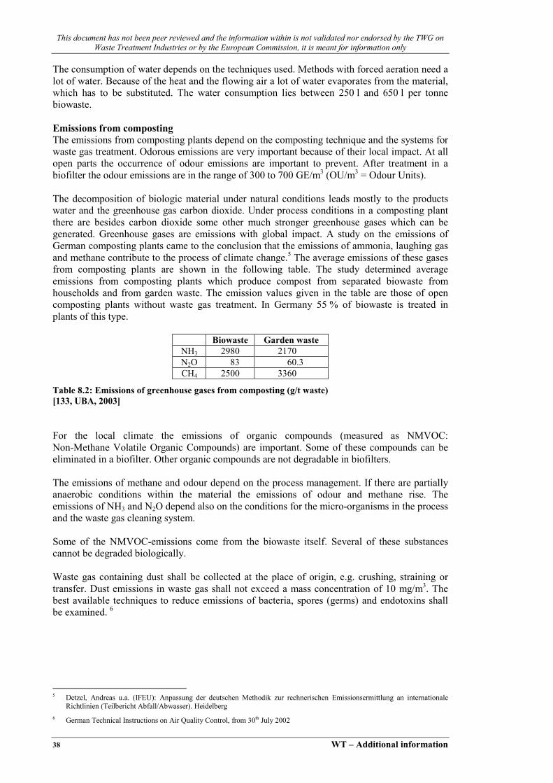
This document has not been peer reviewed and the information within is not validated nor endorsed by the TWG on Waste Treatment Industries or by the European Commission, it is meant for information only
38 WT – Additional information
The consumption of water depends on the techniques used. Methods with forced aeration need a lot of water. Because of the heat and the flowing air a lot of water evaporates from the material, which has to be substituted. The water consumption lies between 250 l and 650 l per tonne biowaste. Emissions from composting The emissions from composting plants depend on the composting technique and the systems for waste gas treatment. Odorous emissions are very important because of their local impact. At all open parts the occurrence of odour emissions are important to prevent. After treatment in a biofilter the odour emissions are in the range of 300 to 700 GE/m3 (OU/m3 = Odour Units). The decomposition of biologic material under natural conditions leads mostly to the products water and the greenhouse gas carbon dioxide. Under process conditions in a composting plant there are besides carbon dioxide some other much stronger greenhouse gases which can be generated. Greenhouse gases are emissions with global impact. A study on the emissions of German composting plants came to the conclusion that the emissions of ammonia, laughing gas and methane contribute to the process of climate change.5 The average emissions of these gases from composting plants are shown in the following table. The study determined average emissions from composting plants which produce compost from separated biowaste from households and from garden waste. The emission values given in the table are those of open composting plants without waste gas treatment. In Germany 55 % of biowaste is treated in plants of this type.
Biowaste Garden waste NH3 2980 2170 N2O 83 60.3 CH4 2500 3360
Table 8.2: Emissions of greenhouse gases from composting (g/t waste) [133, UBA, 2003]
For the local climate the emissions of organic compounds (measured as NMVOC: Non-Methane Volatile Organic Compounds) are important. Some of these compounds can be eliminated in a biofilter. Other organic compounds are not degradable in biofilters. The emissions of methane and odour depend on the process management. If there are partially anaerobic conditions within the material the emissions of odour and methane rise. The emissions of NH3 and N2O depend also on the conditions for the micro-organisms in the process and the waste gas cleaning system. Some of the NMVOC-emissions come from the biowaste itself. Several of these substances cannot be degraded biologically. Waste gas containing dust shall be collected at the place of origin, e.g. crushing, straining or transfer. Dust emissions in waste gas shall not exceed a mass concentration of 10 mg/m3. The best available techniques to reduce emissions of bacteria, spores (germs) and endotoxins shall be examined. 6
5 Detzel, Andreas u.a. (IFEU): Anpassung der deutschen Methodik zur rechnerischen Emissionsermittlung an internationale Richtlinien (Teilbericht Abfall/Abwasser). Heidelberg
6 German Technical Instructions on Air Quality Control, from 30th July 2002

This document has not been peer reviewed and the information within is not validated nor endorsed by the TWG on Waste Treatment Industries or by the European Commission, it is meant for information only
WT – Additional information 39
Description of products generated in composting plants Compost produced from separated household biowaste is a fertiliser and soil conditioner. It contains a high amount of humic substances and its nutrient content (ammonia, phosphorus) is good. Table 8.3 shows the nutrient content of different secondary fertilisers. In anaerobic digestion plants biowaste is often co-digested with agro-industrial by-products or manure and slurry.
Fertilizer dm-content in %
Total N in g/kg mm
NH4-N in g/kg mm
Total P in g/kg mm
P2O5in g/kg mm
Digestate 5 2.7 1.6 0.7 1.6 Biowaste compost 60 6.6 0.3 1.7 3.9 Pig dung 25 11 5.1 3.6 8.2 Cow manure 10 3.8 1.7 1.0 2.3 mm=moist mass
Table 8.3: Nutrient content of different secondary fertilisers [133, UBA, 2003]
The following table shows the average heavy metal pollution of German biowaste composts compared to the limit values of the German ordinance on biowaste 7.
Cd Cr Cu Hg Ni Pb Zn Average concentration in German composts 1999 0.51 25.6 49.6 0.16 15.9 52.7 195
Limit values of the German ordinance on Biowaste 1.5 100 100 1 50 150 400
Table 8.4: Heavy metal content of biowaste composts and limit values of the German ordinance on biowaste (mg/kg dm) [133, UBA, 2003]
Biowaste always contains a percentage of wrongly sorted material which ranges between 0.5 and 6 %. This material (metals, plastics etc.) should be separated by mechanical treatment before and/or after the composting process and should then be transferred to disposal or energy recovery.
8.4 Emissions and consumptions of anaerobic digestion Description of waste treated in anaerobic digestion The aim of anaerobic digestion is to produce a digestate which can be used in agriculture or horticulture as fertiliser or soil conditioner. As a condition for this the contamination of the input material by heavy metals or other pollutants must be kept low. The concentration of pollutants has to comply with the limit values that apply to the use of composts on soil. For this reason it is generally not possible to use mixed municipal waste to produce usable digestate. Only in source-separated biowaste the level of contamination is low enough to allow for the produced digestate to be spread on soil.
7 Ordinance on the Utilisation of Biowastes on Land used for Agricultural, Silvicultural and Horticultural Purposes (Ordinance on Biowastes - BioAbfV), of 21 September 1998

This document has not been peer reviewed and the information within is not validated nor endorsed by the TWG on Waste Treatment Industries or by the European Commission, it is meant for information only
40 WT – Additional information
Sources of the biowaste for the anaerobic digestion can be: • households • food industry. It is also possible to use liquid manure from agriculture in anaerobic digestion plants. Less suitable for anaerobic digestion are materials with high lignin content like wood or green waste from gardens and parks, because lignin cannot be degraded by anaerobic micro-organisms. This kind of green waste should be treated in compost plants. Anaerobic digestion is conducted with a high water content. For dry digestion the input materials contains around 75 % water, for wet digestion the water content amounts to about 90 %. Consumption of anaerobic digestion The process of anaerobic digestion requires more energy than composting. The micro-organisms themselves do not produce enough heat to maintain the appropriate temperature in the reactors. It is thus necessary to heat the anaerobic reactors to maintain the required temperature of about 35 °C for mesophilic or about 55 °C for thermophilic micro-organisms. On the other hand in the anaerobic process a huge amount of biogas is produced by the micro-organisms. About 100 m3 biogas per tonne biowaste can be produced. This gas has an energy content of 5 to 7 kWh/m3. The biogas of one tonne biowaste contains about 500 to 700 kWh energy. If the energy demand of the plant itself is taken into account, one tonne of biowaste yields 100 to 200 kWh of electric power.
Aggregate Energy consumption Mesophilic wet digestion (10 % dm, 21 days)
Electricity 3 kWhel/t input Heat 150 kWhtherm/t input Dewatering 30 kWhel/t input
Thermophilic dry digestion (39 % dm, 21 days) Electricity (total) 80 kWhel/t input Heat (total) 90 kWhtherm/t input
Table 8.5: Energy consumption of anaerobic digestion plants [133, UBA, 2003]
For anaerobic digestion a high water content of the material is important. The different methods require water contents between 75 and 90 %. Therefore it is necessary to add water to most kinds of biowaste. Several anaerobic digestion plants recycle part of the process water after it is separated from the digestate. Emissions from anaerobic digestion The process of anaerobic digestion itself generates no emissions because the reactor is a closed system and the biogas is collected completely for later use. But actually there are emissions from anaerobic digestion plants from the waste delivery, from the pretreatment and after the digestion process from the output material and the after treatment. These emissions include odour, dust and germs and also greenhouse gases and organic compounds. At all open parts the occurrence of odour emissions are important to prevent.

This document has not been peer reviewed and the information within is not validated nor endorsed by the TWG on Waste Treatment Industries or by the European Commission, it is meant for information only
WT – Additional information 41
The decomposition of biologic material under natural conditions leads mostly to the products water and the greenhouse gas carbon dioxide. Under process conditions in an anaerobic digestion plant there are besides carbon dioxide some other much stronger greenhouse gases which can be generated. Emissions of greenhouse gases like ammonia, laughing gas (N2O) and methane are possible at the aerobic after treatment (maturing process) and the use of fresh digestate in agriculture. The emissions from the after treatment of the digestate (composting) and the output of fresh digestate (data taken from the output of liquid manure) are summarised in the following table.
Unit After treatment Output NH3 g/t biowaste 1160 4090 N2O g/t biowaste 28.85 300 CH4 g/t biowaste 750 4000
Table 8.6: Emissions of greenhouse gases from composting (IFEU) [133, UBA, 2003]
Dust and volatile organic compounds (VOC) are possible emissions at the process of waste delivery and at the pretreatment of the biowaste. These parts of the plant have to be in closed halls, so that the waste gas can be collected and treated. Waste gas containing dust shall be collected at the place of origin, e.g. crushing, straining or transfer. Dust emissions in waste gas shall not exceed a mass concentration of 10 mg/m3. The best available techniques to reduce emissions of bacteria, spores (germs) and endotoxins shall be examined. 8
Emissions which do not occur directly at the anaerobic digestion plant are the emissions from the combustion of the biogas. Waste gas concentrations of selected hazardous substances from the biogas combustion are assembled in the following table. There are shown concentrations before and after treatment of the gas in an oxidative catalytic converter.
Raw gas (mg/m3) Clean gas (mg/m3)Carbon monoxide 650 163
Nitrogen oxide 250 250 Sulfur dioxide 756.09 15
NMVOC 50 15 Dust 5 5
Laughing gas 10 10 Methane 30 15
Table 8.7: concentrations of hazardous substances from biogas combustion 9[133, UBA, 2003]
Description of products generated in anaerobic digestion Digestates from anaerobic digestion plants were often after treated in an aerobic digestion (composting). This measure reduces the odour of the product and make it more compatible for horticultural use. Before composting on windrows the digestate has to be dewatered to 60 % dm. It is also possible to use the fresh digestate like liquid manure. The odour is comparable to this of liquid manure. The following table shows the nutrient content of digestate compared to other secondary fertilizers.
8 German Technical Instructions on Air Quality Control, from 30th July 2002 9 Vogt, Regine; u.a. (IFEU): Untersuchung zur Umweltverträglichkeit von Systemen zur Verwertung von biologisch-organischen
Abfällen. Heidelberg 2001

This document has not been peer reviewed and the information within is not validated nor endorsed by the TWG on Waste Treatment Industries or by the European Commission, it is meant for information only
42 WT – Additional information
Fertilizer dm-content in %
Total N in g/kg mm
NH4-N in g/kg mm
Total P in g/kg mm
P2O5in g/kg mm
Digestate 5 2.7 1.6 0.7 1.6 Biowaste compost 60 6.6 0.3 1.7 3.9
Pig dung 25 11 5.1 3.6 8.2 Cow manure 10 3.8 1.7 1.0 2.3
mm=moist mass
Table 8.8: Nutrient content in different secondary fertilizers [133, UBA, 2003]
The content of hazardous substances in digestate from pure biowaste is comparable to the content in compost. But often the biowaste in anaerobic digestion is mixed with waste from agriculture or food industry. That causes the higher content of nutrients but also a higher contamination with Copper and Zinc. Source of both metals are agricultural waste from livestock. The concentration values in the following table are the result of a study in the German region of Brandenburg 10.
Concentration mg/kg dm Fertilizer dm-content in % Pb Cd Cr Cu Ni Hg Zn
Digestate 5 18 0.77 9 196 13 0.29 512 Compost 60 74 0.65 22 60 13 0.18 275
Limiting values of the German ordinance on biowaste
150 1.5 100 100 50 1 400
Table 8.9: Heavy metal content of different secondary fertilizers compared limiting values of the German ordinance on biowaste [133, UBA, 2003]
8.5 Techniques to consider in composting Composting plants considered as best available techniques have to fulfil several conditions: • the delivery and the pretreatment have to take place in closed halls. The waste gas has to be
collected and treated • the intensive composting process (the first days of composting process with very high
emissions) has to be conducted in a closed hall. A forced aeration is needed with a waste gas collecting system and a treatment of waste gas
• the waste gas treatment should contain a biofilter system. Advantageous would be a precedent acid gas washer. An other possibility is a thermal gas treatment
• all places where biowaste is treated need an impermeable base to protect the soil against contaminated liquids.
10 Roschke, M.: Landwirtschaft, Gartenbau und Ernährung; Düngeempfehlungen/Bodenuntersuchungen. http://www.brandenburg.de/land/mlur/l/pflanze/dungmi.htm
This document has not been peer reviewed and the information within is not validated nor endorsed by the TWG on Waste Treatment Industries or by the European Commission, it is meant for information only
WT – Additional information 43
Building and operational requirements The following building and operational requirements shall apply according to the German Technical Instructions on Air Quality Control 11:
• on the basis of estimated monthly utilization, adequate dimensioning, particularly of storage space, shall be undertaken Facilities shall be constructed and operated so that the entry of sewage water into the soil is prevented
• feed bunkers shall be closed and constructed with a vehicle sluice; in open warehouses and during unloading of waste vehicles, the bunker waste gases shall be removed by suction and fed into a waste gas purification facility
• facilities shall be closed during processing as far as possible. This shall apply particularly to facilities with odour-intensive wet or easily biodegradable biowaste (e.g. kitchen or canteen waste) or facilities processing sludge. At plants with an annual throughput of 10000 Mg per year or more facilities (bunkers, compost heaps) shall be kept closed (in-vessel) during processing
• condensed water vapours arising from ventilation of silos and windrows and accumulated seepage water shall only be used in open composting to moisten the compost if olfactory nuisances may be avoided and the hygienic process is not impaired
• in closed facilities or open facilities with an exhaust system, waste gases containing dust shall be collected at the place of origin, e.g. crushing, sifting or transfer. Waste gases from reactors and ventilated windrows shall be supplied to a biofilter or similar waste gas purification facility. The efficiency of biofilters shall be regularly checked in order to guarantee that they comply with purification standards; this may be done by carrying out a compliance audit at least once yearly to ensure that the odorous substance concentration of 500 GE/m3 (odour units per cubic meter) in the waste gas is not exceeded.
8.5.1 Windrow composting plant Description Input: 70 % biowaste, 30 % garden waste, treated waste total 18068 tonnes in 2001 The biowaste and the garden waste were mixed in the bunker. The first step of treatment is the magnet separation (Überbandmagnet) where Fe-metals were separated. After this the biowaste gets to a drum sieve (100 mm holes). From the coarse fraction of the material contraries (Störstoffe) were manual separated before the material will be shredded in a screw mill. The fine fraction also will be optical controlled by men. The composting process take place in a closed composting hall, where the homogenised material is put on windrows. The material on the windrows will be mixed at regular intervals. The intensive digestion last about 3 weeks. After this there will take place a main digestion with 5 weeks and 2 weeks after digestion. The system is build as table windrows (Tafelmiete) with an area of 2000 m2 and an average altitude of 2.5 m. In the first three weeks there is a drawing aeration (suction) (Saugbelüftung) after this there is an optional drawing or pressing aeration (Druckbelüftung).
11 German Technical Instructions on Air Quality Control, from 30th July 2002
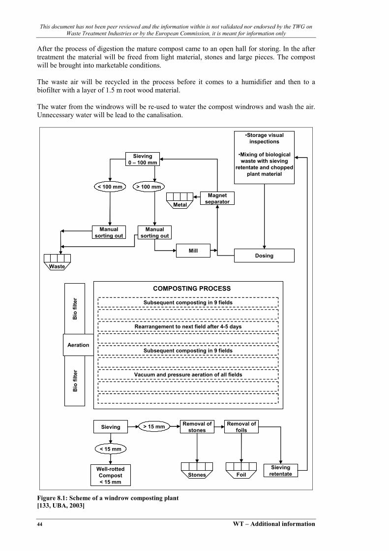
This document has not been peer reviewed and the information within is not validated nor endorsed by the TWG on Waste Treatment Industries or by the European Commission, it is meant for information only
44 WT – Additional information
After the process of digestion the mature compost came to an open hall for storing. In the after treatment the material will be freed from light material, stones and large pieces. The compost will be brought into marketable conditions. The waste air will be recycled in the process before it comes to a humidifier and then to a biofilter with a layer of 1.5 m root wood material. The water from the windrows will be re-used to water the compost windrows and wash the air. Unnecessary water will be lead to the canalisation.
Sieving0 – 100 mm
•Storage visualinspections
•Mixing of biologicalwaste with sieving
retentate and choppedplant material
Magnetseparator
Manualsorting out
Manualsorting out
MillDosing
Metal
< 100 mm > 100 mm
Waste
Subsequent composting in 9 fields
Rearrangement to next field after 4-5 days
Subsequent composting in 9 fields
Vacuum and pressure aeration of all fields
Bio
filte
r
Aeration
Sieving > 15 mm Removal ofstones
Removal offoils
< 15 mm
Well-rottedCompost< 15 mm
SievingretentateStones Foil
Bio
filte
r
COMPOSTING PROCESS
Figure 8.1: Scheme of a windrow composting plant [133, UBA, 2003]

This document has not been peer reviewed and the information within is not validated nor endorsed by the TWG on Waste Treatment Industries or by the European Commission, it is meant for information only
WT – Additional information 45
Achieved environmental benefits There is nearly no waste water from the composting plant, only from toilets and lavatories or at dysfunctions of the process. The water consumption is about 600 l per m3 biowaste. The extensive pre- and after treatment causes a good compost quality which makes the compost good marketable. The compost has a low content of contraries and of heavy metals. The biofilter reduces the odour emissions of 93 %.
Product/waste Amount (t/yr)
Compost 5573 Metals 7
Light waste (plastics etc.) 131 Undegradable material 529
Table 8.10: Products of the composting plant [133, UBA, 2003]
Cross-media effects No data available. Operational data No data available. Applicability This technique is applicable for al regions with a demand for compost and a supply of separated biowaste and/or green waste from gardens. Economics The investigation for the plant have been 10 Million. EUR. The specific costs for the treatment of one tonne of biowaste are 100 Eur. Driving forces for implementation No data available. Reference literature [133, UBA, 2003]
8.5.2 Box composting plant Description Input: 85 % biowaste, 15 % garden waste, treated waste total 16500 tonnes in 2002 After delivering the waste to the bunker it will be put into the shredding facilities using a wheel loader. At this step the biowaste will be mixed with green waste from parks an gardens. It is also possible to add water to dry material. After shredding the material will be filled into the composting boxes using a wheel loader. The dwell time in these boxes is 7 days. During the process temperatures about 60 °C will be reached, so the compost will be free of pathogens, weed seeds and living parts of plants.

This document has not been peer reviewed and the information within is not validated nor endorsed by the TWG on Waste Treatment Industries or by the European Commission, it is meant for information only
46 WT – Additional information
The delivery and the pretreatment and also the composting boxes are situated in closed halls. The waste air of these halls will be collected and used as process air for the forced aeration of the composting boxes. After this the waste air is cleaned in biofilters and treated with ozone before let out through the chimney. The leachate from the intensive composting in the boxes will be recycled and used in the composting boxes again for the humidification of the new material. So there is no waste water from the process. After 7 days of intensive aerobic digestion the material is taken out of the boxes and gets into the aerobic after treatment. The biggest part of the material will be sold after two weeks after composting as a fresh compost to agriculture. This material is sieved at 20 mm. For other purposes a finished compost is needed. This compost needs an after-composting time of 10 to 12 weeks. After this the compost is sieved at 10 mm. In an other step stones, glass etc. can be separated from the material to improve its quality.

This document has not been peer reviewed and the information within is not validated nor endorsed by the TWG on Waste Treatment Industries or by the European Commission, it is meant forinformation only
WT – Additional information 47
SPS
Undesiredcomponents
> 60 mm
“Green” waste andmaterials to enhance
the structuralcomposition
Biologicalwaste
Shredding< 150 mm
Final composting
Intensive compostingin boxes
Well-rottedcompost
Drum sieving0- 10- 60 mm
Compost0-10 mm
< 10 mm
> 60 mm
> 60 mm
10-60 mm
Drum sieving0-20-60 mm Material to enhance structural
composition (20-60 mm)
Compost0-20 mm
Figure 8.2: Scheme of a box composting plant[133, UBA, 2003]

This document has not been peer reviewed and the information within is not validated nor endorsed by the TWG on Waste Treatment Industries or by the European Commission, it is meant for information only
48 WT – Additional information
Achieved environmental benefits The lechate from the composting process will be recycled, so there is no high polluted waste water. Only the condensate from the waste air collecting system has to be treated in a waste water treatment. The waste air from the halls will be re-used as process air in the composting process. So the total amount of waste air can be reduced. The waste air from the composting process will be cleaned in a biofilter. During the treatment of the material 16500 tonnes of biowaste and garden waste is converted into 9000 tonnes of compost. The heavy metal content of the compost is displayed in the following table.
Heavy metal Content (mg/kg dm)
Cd 0.54 Cr 32.0 Cu 72.3 Hg 0.21 Ni 26.6 Pb 52.2 Zn 211
Table 8.11: Heavy metal content in the compost of a composting plant [133, UBA, 2003]
The only waste product are 500 tonnes of sorting rests and material contraries. This waste stream can be recycled. The demand of electricity for the hole treatment is 45 kWh per tonne. Cross-media effects No data available. Operational data No data available. Applicability This technique is applicable for al regions with a demand for compost and a supply of separated biowaste and/or green waste from gardens. Economics No data available. Driving forces for implementation No data available. Reference literature [133, UBA, 2003]

This document has not been peer reviewed and the information within is not validated nor endorsed by the TWG on Waste Treatment Industries or by the European Commission, it is meant for information only
WT – Additional information 49
8.6 Techniques to consider in the anaerobic digestion Reference: [133, UBA, 2003] Anaerobic digestion plants considered as best available techniques have to fulfil several conditions: • the delivery and the pretreatment have to take place in closed halls (in-vessel). The waste
gas has to be collected and treated • the waste gas treatment should contain a biofilter system. Advantageous would be a
precedent acid gas washer. An other possibility is a thermal gas treatment • all places where the biowaste is treated need an impermeable base to protect the soil against
contaminated liquids. Building and Operational Requirements The following building and operational requirements shall apply according to the German Technical Instructions on Air Quality Control 12:
• on the basis of estimated monthly utilization, adequate dimensioning, particularly of the storage space, shall be undertaken Facilities shall be constructed and operated so that the entry of sewage water into the soil is prevented
• feed bunkers shall be closed and constructed with a vehicle sluice; in open warehouses and during unloading of waste vehicles, the bunker waste gas shall be removed by suction and fed into a waste gas purification facility
• processing water is to be retained and put to internal use • the condensed water vapours arising from ventilation of the windrows (maturing process)
and the accumulated seepage water shall only be used in open composting to moisten the compost if olfactory nuisances may be avoided
• in closed facilities or open facilities with an exhaust system, waste gases containing dust shall be collected at the place of origin, e.g. crushing, sifting or transfer
• waste gases from the maturing process in ventilated windrows shall be fed into a biofilter or equivalent waste gas purification facility. The efficiency of biofilters shall be regularly checked in order to guarantee that they comply with purification standards; this may be done by carrying out a compliance audit at least once yearly to ensure that the odorous substance concentration of 500 GE/m3 (odour units per cubic meter) in the waste gas is not exceeded.
8.6.1 Thermophilic anaerobic digestion plant Description Input: 26 % biowaste from households, 45 % organic waste from industry (food waste) and 29 % waste from agriculture, treated waste total 31000 tonnes in 2002 From the bunker the biowaste goes via a mill to the wet conditioning of the waste. The conditioning consists of a pulper and a drum sieve. After that the biowaste will be mixed with the liquid manure, the food waste and the waste from slaughter houses. The waste from slaughter houses and the food waste have been heated up to 90 °C before.
12 German Technical Instructions on Air Quality Control, from 30th July 2002

This document has not been peer reviewed and the information within is not validated nor endorsed by the TWG on Waste Treatment Industries or by the European Commission, it is meant for information only
50 WT – Additional information
After mixing the different waste streams the material gets into one of the two anaerobic digestion reactors with a dry matter content of 12 %. The treatment in the 55 °C warm reactor last about 18 days. The average amount of gas received from this treatment is 81 m3/t waste with an average methane content of 73 %. The gas will be cleaned from H2S before it can be used in a block heat and power plant. After subtracting the energy need of the plant itself (42 kWh/t waste) it is possible to sell 97 kWh electric energy from one tonne of waste. It is also possible to give away a lot of heat. More than 97 % of the liquid digestate will be used directly as a fertilizer for agricultural purpose. Only 3 % of the material will be dewatered and sell as a kind of fresh compost.
Storage
Deactivation
•Shredding• Removal of
undesiredcomponents
Hydraulic buffer,hydrolysis
Biogasreactor
Storage forliquid
fertiliser
Combinedcycle power
plant
Biofilter
Partialdrying
Biogas
Process water Well-rottedcompost
Treatedwaste gas
Liquidfertiliser
Electricity
Heat
On siteuse
Liquid manure
Other wastes
Wastes for deactivation
(hygiene)
Undesiredcomponents
Biologicalwastes
Figure 8.3: Scheme of a anaerobic digestion plant [133, UBA, 2003]
Achieved environmental benefits The waste air from the delivery and the pretreatment will be cleaned in a biofilter. There is no waste water to clean because the water leave the process with the liquid product. This procedure is only economical and ecological reasonable while the users of the digestate are situated near to the plant.
Content Element mg/l mg/kg dm Cd 0.041 0.88 Cr 0.813 17.1 Cu 11.25 244.8 Hg 0.02 0.41 Ni 0.97 20.0 Pb 2.25 47.9 Zn 22.1 476.5
Table 8.12: Heavy metal content of the liquid digestate [133, UBA, 2003]

This document has not been peer reviewed and the information within is not validated nor endorsed by the TWG on Waste Treatment Industries or by the European Commission, it is meant for information only
WT – Additional information 51
Cross-media effects No data available. Operational data No data available. Applicability No data available. Economics The investigations have been 7.5 Million. EUR. The specific costs for the treatment of one tonne of biowaste are 23 EUR. Driving forces for implementation No data available. Reference literature [133, UBA, 2003]


This document has not been peer reviewed and the information within is not validated nor endorsed by the TWG on Waste Treatment Industries or by the European Commission, it is meant for information only
WT – Additional information 53
9 RECYCLING OF MERCURY CONTAINING DISCHARGE LAMPS
Reference: [150, TWG, 2004] More than 850 million discharge lamps (fluorescent lamps, high pressure mercury vapour lamps, high pressure sodium vapour lamps, metal halide lamps, compact fluorescent lamps) are sold in Europe every year. Since the lamps contain environmentally relevant mercury (Hg), they have to be regarded as hazardous waste after burn-out and are therefore in a lot of countries subject to specific legal regulations for disposal. These lamps are also a category of the Directive on Waste of Electric and Electronic Equipment, WEEE which will come into force in the near future. A number of different recycling processes have been developed and are in commercial use at present. Most of them involve dismantling or shredding - either wet or dry - at a mobile or stationary plant. The recycling technology developed by WEREC® is a dry technique that involves dismantling at a stationary plant. When being dismantled discharge lamps are being taken apart in the reverse order of the one followed in manufacturing of them. In contrast to shredding, which involves crushing of lamps in their entirety and distribution of the mercury on the materials unloaded until then, WEREC's procedure allows recovering of substances and groups of substances separately. The mercury is caught in one fraction. In a dry recycling process mercury and dust can be separated from the exhaust air in a very simple and efficient manner without leaving behind any hydrous solution, which would have to be disposed of as hazardous waste. Stationary plants are much more environmentally compatible than mobile plants are, because the latter require the whole recycling equipment to be put on a lorry, with some lamps inevitably breaking during on-the-spot processing and thus potentially causing damage to the environment. The recycling plants for mercury containing discharge lamps described here are highly productive and very environmentally compatible. Dispensing with the use of water, it permits recovering main quantity of the materials of burnt-out lamps for re-use in the manufacture of new lamps. It is state-of-the-art equipment. A great deal of research and development as well as other innovative work is being done to increase the recyclability of lamps even further and develop processes and plants that allow recycling additional types of discharge lamps.
9.1 Linear Fluorescent Lamps Most discharge lamps for recycling are linear fluorescent lamps (75 %). WEREC's recycling plant, which is capable of processing several 1000 fluorescent lamps every hour, is fully automatic except for lamp loading. In the cap-separating machine, type of phosphor of each lamp is at first detected to precipitate the recyclable rare earth-activated phosphors separately from the halophosphate phosphor. After detection of phosphor, lamps are aerated with a spot burner, their two ends (caps) are broken off by heating and cooling, and their phosphor powder (approx 2.5 mass-%), which contains small amounts of mercury (approx 10 mg per lamp), is blown out of the glass tube in separated types. The different types of phosphor are taken out of the exhaust air via cyclones. About 60 % of the amount of the phosphor powder are rare earth activated phosphors (1.5 mass-% of the lamps) and they are delivered back to the lamp producing industry for re-use. It is expected that the part of tricolour fluorescent lamps with rare earth-activated phosphors will grow in the future and therefore the mass of recycled phosphor will additionally rise. As a result the share of non usable phosphor (1.0 mass-%) which still has to be disposed of as hazardous waste will go down in future.

This document has not been peer reviewed and the information within is not validated nor endorsed by the TWG on Waste Treatment Industries or by the European Commission, it is meant for information only
54 WT – Additional information
After this the fine dust parts of phosphors are removed via a fine dust filter, and the mercury is adsorbed by a following activated carbon filter (See Figure 9.1).
Recovery of mercury
Purified exhaust air
Utilization of the glass tubes
Cyclone 1
Cyclone 2
Cyclone 3
Dump 1.0 %Lamp industry1.5 %
Vibrating fluid bed 85.5 %
Vibrating sieve 12 %
Utilization of the
lamp ends
Crusher
Lamp ends
Crusher
Broken glass
Rare earth-activated phosphors
Other phosphors and fine dust
Activated carbon filterFine dust
filter
Blowing out position 1
Blowing out position 2
Blowing out position 3
Opto-electronicaldetection of phosphor
Figure 9.1: Dismantling of linear fluorescent lamps [150, TWG, 2004]
The free of phosphor glass tube is reduced to small pieces of between 1 and 2 cm in a crusher and subsequently subjected to thorough final cleaning in a vibrating fluid bed. Passing through the bed, the pieces of glass continuously undergo rapid acceleration. They push and rub each other, which serves to efficiently remove the little remaining mercury and phosphor and also other impurities clinging to the surface of the glass. The impurities that have been removed in this way are carried off by the hot air flowing through the bed from bottom to top at high speed, and are taken out via the cyclone, the fine dust filter and the activated carbon filter (See Figure 9.2).
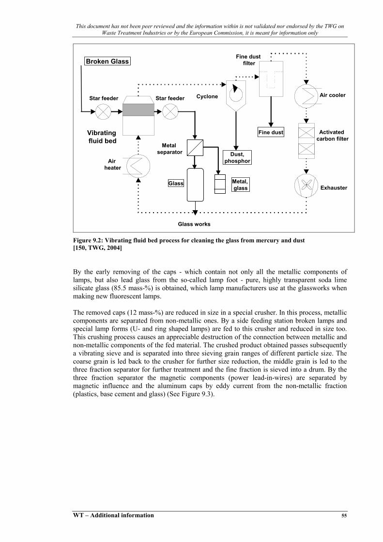
This document has not been peer reviewed and the information within is not validated nor endorsed by the TWG on Waste Treatment Industries or by the European Commission, it is meant for information only
WT – Additional information 55
Cyclone
Dust,phosphor
Vibratingfluid bed
Fine dust
Fine dustfilter
Air cooler
Activated carbon filter
Exhauster
Airheater
Metal, glass
Glass
Metalseparator
Broken Glass
Glass works
Star feederStar feeder
Figure 9.2: Vibrating fluid bed process for cleaning the glass from mercury and dust [150, TWG, 2004]
By the early removing of the caps - which contain not only all the metallic components of lamps, but also lead glass from the so-called lamp foot - pure, highly transparent soda lime silicate glass (85.5 mass-%) is obtained, which lamp manufacturers use at the glassworks when making new fluorescent lamps. The removed caps (12 mass-%) are reduced in size in a special crusher. In this process, metallic components are separated from non-metallic ones. By a side feeding station broken lamps and special lamp forms (U- and ring shaped lamps) are fed to this crusher and reduced in size too. This crushing process causes an appreciable destruction of the connection between metallic and non-metallic components of the fed material. The crushed product obtained passes subsequently a vibrating sieve and is separated into three sieving grain ranges of different particle size. The coarse grain is led back to the crusher for further size reduction, the middle grain is led to the three fraction separator for further treatment and the fine fraction is sieved into a drum. By the three fraction separator the magnetic components (power lead-in-wires) are separated by magnetic influence and the aluminum caps by eddy current from the non-metallic fraction (plastics, base cement and glass) (See Figure 9.3).

This document has not been peer reviewed and the information within is not validated nor endorsed by the TWG on Waste Treatment Industries or by the European Commission, it is meant for information only
56 WT – Additional information
Magnetic metal Glass, plastics
Three fraction separator
Non-magnetic metal, Al
Crusher
Fine grain, phosphor
Fine grain, phosphor
Coarse grain
Middle grain
Side feeding station for broken lamps and special shapes
Broken lamp caps
Vibrating chute
Main air exhaustion
Figure 9.3: Vibrating sieve process for separation and cleaning of the lamp end components and special shapes [150, TWG, 2004]
The two metal fractions (2.7 mass-%) go into metal processing, while the non-metallic remainder (9.3 mass-%), which consists of a harmless mix (lead glass, soda lime silicate glass, base cement and plastics), can be used as building material additive, for glazing, for filling up disused mines, etc. The fluorescent lamp’s recycling rate is at present 99 %.
9.2 High Intensity Discharge Lamps In high intensity discharge (HID) lamps, it is only the so-called burner that contains environmentally relevant mercury - in the form of pure mercury in the case of high pressure mercury vapour lamps, and in the form of sodium amalgam in the case of high pressure sodium vapour lamps. HID lamps provide a particularly fine demonstration of the advantages that dismantling en-joys over shredding. An automatic high effective plant was developed and is in operation (See Figure 9.4).

This document has not been peer reviewed and the information within is not validated nor endorsed by the TWG on Waste Treatment Industries or by the European Commission, it is meant for information only
WT – Additional information 57
Glass Works64 %
Residual Materials4 %
Metal Utilization32 %
RackBroken glass Coating
substance
Vibrating fluid bed
Basepart
Machine housing
Main air exhaustionGlass detection bylaser spectroscopy
Crusher
Burner material ofhigh pressure
mercury lamps
Burner materialtreatment of highpressure sodium
lamps
Crushing ofpump pipe
and rackcut off
Separation andcrushing of
burnerPosition 1
hardglass
Position 2
softglass
Position 3
leadglass
Position 4
otherglass
Outer bulb Cut off
Figure 9.4: Dismantling of high intensity discharge lamps [150, TWG, 2004]
At first a laser spectroscopic detection of bulb glass types (64 mass-%) takes place. After that the bulbs are cut off, separated in maximum four glass types (e g borosilicate glass, soda lime silicate glass, lead glass, other glass). The bulb glass is crushed and the coating is removed in the vibrating fluid bed. The purified glass is put to its proper use at the glass works. The rack (7 mass-%), which is made up of nickel or an iron-nickel alloy, and the base (22 mass-%), which consists of brass, go into metal recycling. After remove of mercury the burner material (quartz glass or aluminum oxide ceramic) can be fed to a utilization e g as building material additive or for filling up disused mines. A special process was developed for the burners of high pressure sodium vapour lamps (See Figure 9.5). After treatment of the broken aluminum oxide ceramic burners, sodium amalgam is transformed into a harmless sodium compound and mercury. The treatment given to the crushed burners takes place in what is virtually a dry process. Only minutest quantities of acid component are added to hasten the decomposition of sodium amalgam. The acid is subsequently neutralised with an overabundance of basic component so that a dry product is obtained that is capable of trickling and can easily be subjected to further treatment or disposal.

This document has not been peer reviewed and the information within is not validated nor endorsed by the TWG on Waste Treatment Industries or by the European Commission, it is meant for information only
58 WT – Additional information
Reaction vesselPump
Drum
Crusher
Storage tank foracid component
Conveyor
Storage bin for basic component
Burners of high pressuresodium vapour lamps
Figure 9.5: Treatment of burners of high pressure sodium vapour lamps [150, TWG, 2004]
9.3 Compact Fluorescent Lamps There are CFL with pin and screw base and a lot of different glass vessels. A container with about 1000 CFL is tipped down on a big rotating plate which individualizes on small rotating plates. These small plates are fastened at a conveyor. The small plates are aligned in such manner that the glass vessel of the CFL always show in one direction. Now the glass vessels are cut off from the base part. The whole base parts go to an electronic recycling plant. The glass vessels are crushed and after that treated in the vibrating fluid bed for removing of the phosphor powder and mercury. Without the phosphor all other substances can be re-used (See Figure 9.6).

This document has not been peer reviewed and the information within is not validated nor endorsed by the TWG on Waste Treatment Industries or by the European Commission, it is meant for information only
WT – Additional information 59
Machine housing
Cut off
Electronic waste recycling
60 %
Glassrecycling
39 %
Vibrating fluid bed
Glass vessel
Broken glassRare earths
activated phosphors
Phosphor, mercury
1 %
Crusher
Main air exhaustion
Figure 9.6: Dismantling of compact fluorescent lamps [150, TWG, 2004]
9.4 High Environmental Compatibility A whole range of measures was taken to ensure high environmental compatibility and avert danger to humans and nature at the plant site to a very considerable extent. • the floors of the loading, storage and processing rooms were given the shape of troughs to
prevent the escape of water that may have been used to extinguish a fire • a large 20 m x 45 m loading room was provided so that whole trucks can be loaded and
unloaded indoors without wind or rain carrying off harmful substances • the plant is equipped with two airing systems with identical filter technique. The waste air
system in the plant's main section sucks out 3.000 cubic metres of air every hour, thus keeping the plant under constant subatmospheric pressure and, in a way, rinsing the processing room. After the plant has been switched off, the system goes on running at half the air throughput (1.500 cubic metres per hour), to prevent mercury from accumulating in the processing room even when the plant is not in operation
• to increase the vibrating fluid bed's purifying effect, the air is heated. To keep energy consumption low, the bed has been provided with a circulating air system (moving 1.700 cubic metres of air every hour). Air circulation in the bed does away with the need for continuously heating the required air from room temperature to process temperature. The sophisticated filtering equipment, which consists of a cyclone, a fine dust filter and a two-stage activated charcoal filter, provides near-clean-room air. There is a constant subatmospheric pressure in the plant even in the air circulation, maintained by the air exhaust system
• the locker rooms for the shop floor staff follow what is called the black-and-white principle. Staff keep their personal clothes in what is called the white locker room and their work clothes in what is called the black locker room. Air is sucked from the latter day and night
• the water that staff use when taking showers and washing their hands is caught in a specially provided sewage tank so that it can be checked for mercury before it is taken away.

This document has not been peer reviewed and the information within is not validated nor endorsed by the TWG on Waste Treatment Industries or by the European Commission, it is meant for information only
60 WT – Additional information
The data measured in the air escaping into the surroundings are given in the following chart.
Concentration in mg/cubic metre Substance permissible after TA-Luft 1) achieved in the plant Mercury 0.05 <0.005 Dust 5.0 <0.020 Note: 1) TA-Luft = Technical Instruction "Air"
Table 9.1: Data measured int he air escaping into the surroundings [150, TWG, 2004]
A monitor at the waste air chimney measures and records mercury concentration 24 hours a day.

This document has not been peer reviewed and the information within is not validated nor endorsed by the TWG on Waste Treatment Industries or by the European Commission, it is meant for information only
WT – Additional information 61
REFERENCES 133 UBA (2003). "German comments to the Draft BREF on Waste Treatments. Biological
treatments of separated biowaste", UBA, Ecologic. 150 TWG (2004). "Comments to the second draft of the WT BREF". 156 VROM (2004). "Dutch fact sheets for the waste treatment industries", Ministry of
Housing, Spatial Planning and the Environment. Directorate for Chemicals, Waste, Radiation protection. Department of hazardous waste.