AddisonMckee Tube Bending Guide · AddisonMckee Tube Bending Guide FAULT FINDER FITTING A WIPER DIE...
1
AddisonMckee Tube Bending Guide FAULT FINDER BALL MANDREL SELECTION CHART FITTING A WIPER DIE Marking on tube centreline Bend Die Clamp Die Pressure Die Mandrels Wiper Dies Hump at the end of a bend Deep scratches in bend/Wiper Die Area Tool marks on tube in clamp area Wrinkling in bend area Tube breakage in bending Tube collapses either with or without wrinkling through full bend Wrinkles on bend with all tools in correct position Excessive springback Selected according to tube OD (outside diameter) and CLR (centre line radius) requirements. Dies are manufactured from various grades of steel dependant upon the type of application. The dies should be a good fit onto the machined register on the bend head, and must always be securely fastened down. a) Check the alignment of Pressure Die and Clamp b) Check dimension of tube in relation to tool set c) Check to ensure all tools are free of dirt and scale – if not clean all tools d) Check that tube is clean and free of oil and grease a) Check alignment of Clamp b) Check Pressure of Clamp on Tube c) Check that Clamp is clean and free of oil and grease a) Check for Clamp Slip b) Check that there is sufficient Pressure Die Boost c) Check position of Mandrel a) Mandrel advanced too far forward – reset to tangent b) Check free movement of Pressure Die a) Check condition of Wiper Die – if worn recut or replace b) Decrease rake on Wiper Die c) Advance Wiper closer to tangent point and check that position is correct and that Wiper is secured correctly a) Increase rake or relief of Wiper Die b) Check Wiper Die edge for pitting or scores – if present recut or replace c) Check that Wiper Die is not dry, Lubricate if required a) Check that elongation of material is suitable for bending b) Check Clamp and Pressure Die settings c) Check position of Mandrel d) Check that Pressure Die is moving freely a) Check Mandrel size and fit b) Increase Pressure Die force a) Check that Pressure Die is not holding the tube back during bending b) Check ductile strength of tube and programme overbend to compensate Selected to match the Bend Die. Clamp Dies may be manufactured with various finishes to improve tube grip. The Clamp should be adjustable for vertical alignment and parallel contact along its length. Use of ‘Ball’ type Mandrels, selected according to our Mandrel Selection Guide below, will ensure quality bends. When setting up Ball Mandrels it is important to ensure that the leading end of the Shank is on Centre Line when bending. The Balls should be forward of this point. The Wiper Die is selected for use with a Ball Mandrel. The purpose of a Wiper Die is to stop wrinkles from forming on the inside of the bend at the tangent point. Wiper Die requirements are listed on our Mandrel Selection Guide. Wiper Dies are available in the following materials: Mild Steel, Tool Steel, Ampco Bronze. It is important to ensure that Wiper Dies are lubricated at regular intervals. For fitting instructions see below. IMPORTANT: Setting of the Mandrel should be carried out with the Mandrel fully forward not retracted. Mandrels are manufactured in the following materials: Case Hardened Steel; Tool Steel; Ampco Bronze; and are provided with lubrication grooves. A variety of finishes can be provided according to your requirements. Selected to match the CLR (centre line radius) of the Bend Die. Die length is critical and is determined by the following formula, assuming that full 180 degree bends are required: CLR x 3 . 14 ÷ 180 x 195 + 3 x tube OD Example: 1” OD tube x 4” CLR 4” x 3.14 = 12.56” ÷ 180 x 195 = 13.60” + 3” = 16.60” The Die should be adjustable for vertical alignment. 1 1 5 5 4 4 3 3 2 2 i) Mount the Wiper Die onto its bracket with the bolts finger tight. ii) Load a sample tube to be bent, clamped so that it extends back past the end of the Wiper Die. iii) Close the Pressure Die and tap the Wiper Die forward into the Die Bend groove with a soft mallet. Tighten all Wiper Die mounting bolts. iv) Open the Pressure Die and remove the tube. The Wiper Die should reach almost to the Bend Die tangent point. When a straight edge is held in the bottom of the Bend Die grip area, it should lie flat along the bottom of the die grooves. v) Check that the heel of the Wiper Die lies close to the bend die but does not dig in. The shape of both mating faces should match exactly. The chart on the left details when a ball mandrel and/or wiper die is required. The calculations to determine this criteria are based on the following: A Ratio of Tube OD to Wall Thickness B Ratio of Tube OD to Centre Line Radius On a 2D bend a Ratio of 50 indicates that a 4 Ball Mandrel and Wiper Die should be selected. In some cases reducing the specification by one ball will reduce the drag and give satisfactory bend. Trials are the only real way of gauging this. FERROUS NON-FERROUS i) Numbers indicate number of balls required on Mandrel. ii) Light blue indicates Wiper Die recommended. 1 1.5 2 2.5 3 5 10 20 1 2 1 2 1 2 2 2 30 3 3 3 3 3 3 2 3 2 3 2 40 3 4 3 4 3 4 3 3 3 3 1 2 50 4 5 4 5 4 5 4 4 3 4 2 3 60 5 5 5 5 4 5 4 5 4 4 3 3 70 5 5 5 5 4 5 4 5 4 5 3 5 80 5 5 5 5 4 5 4 5 4 5 4 4 90 5 5 5 5 5 5 5 5 5 5 5 5 100 5 5 5 5 5 5 5 5 5 5 5 5 125 5 5 5 6 5 5 5 5 5 5 5 5 150 5 5 5 6 5 6 5 5 5 6 5 6 175 6 5 5 6 5 8 5 8 6 7 200 6 5 6 5 5 5 7 10 Ratio of CLR Tube OD Ratio of Tube Tube OD WT Ratio of Tube OD WT 50mm 1mm Ratio of 50 = Ratio of CLR Tube OD 100 50 Ratio of 2 =
Transcript of AddisonMckee Tube Bending Guide · AddisonMckee Tube Bending Guide FAULT FINDER FITTING A WIPER DIE...
AddisonMckee Tube Bending Guide
FAULT FINDER
BALL MANDREL SELECTION CHARTFITTING A WIPER DIE
Marking on tube centreline
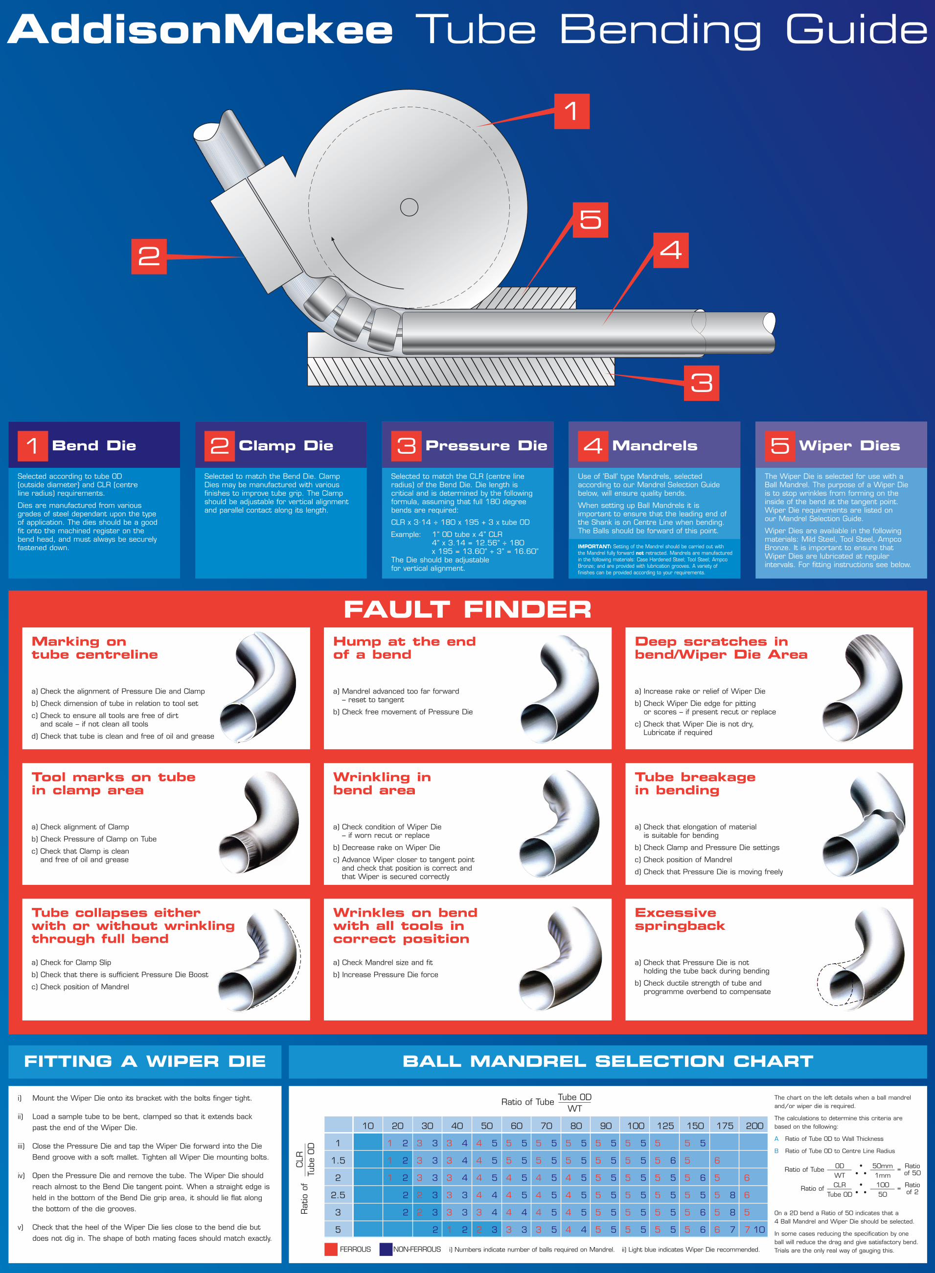
Bend Die Clamp Die Pressure Die Mandrels Wiper Dies
Hump at the end of a bend
Deep scratches in bend/Wiper Die Area
Tool marks on tube in clamp area
Wrinkling in bend area
Tube breakage in bending
Tube collapses either with or without wrinklingthrough full bend
Wrinkles on bendwith all tools incorrect position
Excessivespringback
Selected according to tube OD (outside diameter) and CLR (centre line radius) requirements.
Dies are manufactured from various grades of steel dependant upon the type of application. The dies should be a good fit onto the machined register on the bend head, and must always be securelyfastened down.
a) Check the alignment of Pressure Die and Clamp
b) Check dimension of tube in relation to tool set
c) Check to ensure all tools are free of dirt and scale – if not clean all tools
d) Check that tube is clean and free of oil and grease
a) Check alignment of Clamp
b) Check Pressure of Clamp on Tube
c) Check that Clamp is clean and free of oil and grease
a) Check for Clamp Slip
b) Check that there is sufficient Pressure Die Boost
c) Check position of Mandrel
a) Mandrel advanced too far forward – reset to tangent
b) Check free movement of Pressure Die
a) Check condition of Wiper Die – if worn recut or replace
b) Decrease rake on Wiper Die
c) Advance Wiper closer to tangent point and check that position is correct and that Wiper is secured correctly
a) Increase rake or relief of Wiper Die
b) Check Wiper Die edge for pitting or scores – if present recut or replace
c) Check that Wiper Die is not dry, Lubricate if required
a) Check that elongation of material is suitable for bending
b) Check Clamp and Pressure Die settings
c) Check position of Mandrel
d) Check that Pressure Die is moving freely
a) Check Mandrel size and fit
b) Increase Pressure Die force
a) Check that Pressure Die is not holding the tube back during bending
b) Check ductile strength of tube and programme overbend to compensate
Selected to match the Bend Die. ClampDies may be manufactured with variousfinishes to improve tube grip. The Clampshould be adjustable for vertical alignmentand parallel contact along its length.
Use of ‘Ball’ type Mandrels, selectedaccording to our Mandrel Selection Guidebelow, will ensure quality bends.
When setting up Ball Mandrels it isimportant to ensure that the leading end ofthe Shank is on Centre Line when bending.The Balls should be forward of this point.
The Wiper Die is selected for use with aBall Mandrel. The purpose of a Wiper Die is to stop wrinkles from forming on theinside of the bend at the tangent point.Wiper Die requirements are listed on our Mandrel Selection Guide.
Wiper Dies are available in the followingmaterials: Mild Steel, Tool Steel, AmpcoBronze. It is important to ensure that Wiper Dies are lubricated at regularintervals. For fitting instructions see below.
IMPORTANT: Setting of the Mandrel should be carried out with the Mandrel fully forward not retracted. Mandrels are manufacturedin the following materials: Case Hardened Steel; Tool Steel; AmpcoBronze; and are provided with lubrication grooves. A variety offinishes can be provided according to your requirements.
Selected to match the CLR (centre lineradius) of the Bend Die. Die length is critical and is determined by the followingformula, assuming that full 180 degreebends are required:
CLR x 3.14 ÷ 180 x 195 + 3 x tube OD
Example: 1” OD tube x 4” CLR4” x 3.14 = 12.56” ÷ 180x 195 = 13.60” + 3” = 16.60”
The Die should be adjustable for vertical alignment.
1
1
5
5
4
4
3
3
2
2
i) Mount the Wiper Die onto its bracket with the bolts finger tight.
ii) Load a sample tube to be bent, clamped so that it extends back
past the end of the Wiper Die.
iii) Close the Pressure Die and tap the Wiper Die forward into the Die
Bend groove with a soft mallet. Tighten all Wiper Die mounting bolts.
iv) Open the Pressure Die and remove the tube. The Wiper Die should
reach almost to the Bend Die tangent point. When a straight edge is
held in the bottom of the Bend Die grip area, it should lie flat along
the bottom of the die grooves.
v) Check that the heel of the Wiper Die lies close to the bend die but
does not dig in. The shape of both mating faces should match exactly.
The chart on the left details when a ball mandreland/or wiper die is required.
The calculations to determine this criteria are based on the following:
A Ratio of Tube OD to Wall Thickness
B Ratio of Tube OD to Centre Line Radius
On a 2D bend a Ratio of 50 indicates that a 4 Ball Mandrel and Wiper Die should be selected.
In some cases reducing the specification by one ball will reduce the drag and give satisfactory bend.Trials are the only real way of gauging this.FERROUS NON-FERROUS i) Numbers indicate number of balls required on Mandrel. ii) Light blue indicates Wiper Die recommended.
1
1.5
2
2.5
3
5
10 20
1 2
1 2
1 2
2
2
30
3 3
3 3
3 3
2 3
2 3
2
40
3 4
3 4
3 4
3 3
3 3
1 2
50
4 5
4 5
4 5
4 4
3 4
2 3
60
5 5
5 5
4 5
4 5
4 4
3 3
70
5 5
5 5
4 5
4 5
4 5
3 5
80
5 5
5 5
4 5
4 5
4 5
4 4
90
5 5
5 5
5 5
5 5
5 5
5 5
100
5 5
5 5
5 5
5 5
5 5
5 5
125
5 5
5 6
5 5
5 5
5 5
5 5
150
5 5
5 6
5 6
5 5
5 6
5 6
175
6 5
5 6
5 8
5 8
6 7
200
6 5
6 5
5 5
7 10
Ratio of
CLR
Tube OD
Ratio of Tube Tube ODWT
Ratio of Tube ODWT
50mm1mm
Ratio of 50=
Ratio of CLRTube OD
10050
Ratio of 2=
For more information please contactAddisonMckee, UKUK188 Bradkirk Place,
Walton Summit Centre Bamber Bridge
Preston, Lancashire PR5 8AJ UK
Tel: +44.1772.334511
AddisonMckee, USA1637 Kingsview Drive
Lebanon, Ohio 45036 USA
Tel: +1.513.228.7000
AddisonMckee, Canada31 Adams Boulevard
Brantford, Ontario
N3S 7V8 Canada
Tel: +1.519.720.6800