Adding rasterization to a ‘closed’ design with no negative ...
7
1 Adding rasterization to a ‘closed’ design with no negative space increases the life of the garment by letting water and heat pass through more easily during each wash cycle, and allows for stretching of the garment and transfer without damage. It will also soften up the printed image and allow the garment to ‘breathe’ more naturally when worn. There are 2 ways to add rasterization effects to your image. Option 1: Rasterizing the entire image. Choose your media with either ‘holes’ or ‘stripes’. This option applies a uniform raster screen across the entire image and does not require any special setup in your original artwork. Graphical representation from the ProRIP with uniform holes:
Transcript of Adding rasterization to a ‘closed’ design with no negative ...

1
Adding rasterization to a ‘closed’ design with no negative space increases the life of the garment by letting
water and heat pass through more easily during each wash cycle, and allows for stretching of the garment and
transfer without damage. It will also soften up the printed image and allow the garment to ‘breathe’ more
naturally when worn. There are 2 ways to add rasterization effects to your image.
Option 1:
Rasterizing the entire image. Choose your media with either ‘holes’ or ‘stripes’. This option applies a uniform
raster screen across the entire image and does not require any special setup in your original artwork.
Graphical representation from the ProRIP with uniform holes:

2
Graphical representation from the ProRIP with uniform lines:
The size of the dots or lines is adjusted in the ‘Easy Color Adjustments’ window by clicking ‘Color Adjust’ after
your image is loaded, and is controlled by the ‘Dot Size’ slider. Sliding to the left makes the holes or lines
bigger, and sliding to the right makes them smaller. A value of 255 is equivalent to ‘off’. UniNet suggests using
the default parameter of 180 for best results.
Option 2:
By default, the ProRIP will automatically and variably rasterize portions of your graphic that fade out. Since
there is no way for transfer media to do this on its own, the RIP will apply appropriate sized holes to your
graphic in those areas that represent fades. Typically seen with images such as clouds, or smoke that, by their
very nature, fade to nothing. The software looks for areas of transparency in the design and applies holes
(small to large) across the design in the areas where there is a fading (transparent) effect. This effect won’t be
seen until you either import an image that has some partial transparency or you import a raster image and
then remove a color such as black, thus creating partial transparency.

3
The images below show what happens with variable rasterization after black is removed from the image. The
image to the left is the original image file. The image to right is already pressed to a black shirt after the black
elements are removed and automatic variable rasterization is applied.
You may also want to rasterize certain parts of the image without removing a color. For example, if you are
recreating a company logo with a large design behind it and only want to rasterize the background, but not
the logo itself. To achieve this, you would create or modify the specific parts of image using partial
transparency in your favorite art software. The more transparency the image has, the more rasterization the
ProRIP will apply. Below is an example of an image with this type to rasterization applied. Since this is
automatic and built in as a default option in the RIP, the user does not have to do anything except import and
print. Notice that the logo shows full screening and the rest of the image is rasterized. Additionally, notice the
outside border of the background shows increasing sized dots as it fades to nothing.

4
Original graphic with 70% Opacity /
30% transparency applied to the
background only:
Preview of how the graphic will print:
Zoomed in area variable rasterization:

5
Finished product pressed onto a black shirt:
Zoomed in to show variable
dot pattern:
The size of the dots is controlled in the ‘Easy Color Adjustments’ window, when the ‘Use graphics transparency
for dot size’ option is checked. The ‘Adjust Holes’ slider controls the size of the automatic variable
rasterization based on object transparency. UniNet suggests using the default parameter of .70 for best
results. Uncheck if you do not want automatic variable rasterization based on transparency.

6
It is also possible to combine effects by using both forced rasterization (option 1) and automatic rasterization
(option 2). The RIP will force rasterization in areas where there is no partial transparency and will use variable
dot sizes in areas that do.
Adjusting the Frequency, Angle and Shape of Raster Lines or Dots
To alter the properties of the forced or variable holes or stripes in your image, double click the image you
want to adjust in the Print Queue > Color Layer > Halftones. With the ‘Enable halftoning’ option checked, the
Frequency, Angle and Shape may be adjusted freely. All four colors must be changed, but the benefit is each
color can be controlled separately. For example, CMY can be at one angle and the K can be a different angle,
should you so choose that look.
Halftone Settings
Frequency - The halftone frequency is measured in Lines Per Inch (lpi), which indicates the resolution of the
dot shape. This option will dither the lines or holes in the design.
Angle - To avoid unexpected patterns from appearing in the final print, each of the CMYK separations must be
printed at specific angles. The choice of angles is quite subjective, though specific angles may be preferred
according to the printing technology being used. The default angle of 52 avoids undesirable moiré patterns.
Shape - There are a wide variety of shapes to choose for your halftone dots or lines. The choice of shape
depends on what the user determines will produce good detail in your prints. For example, round and elliptical
shapes are common, though test prints can determine whether other shapes are acceptable for the chosen
artwork.
7
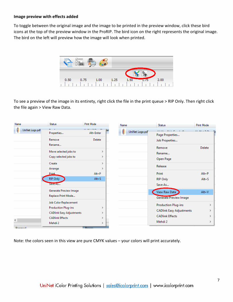
Image preview with effects added
To toggle between the original image and the image to be printed in the preview window, click these bird
icons at the top of the preview window in the ProRIP. The bird icon on the right represents the original image.
The bird on the left will preview how the image will look when printed.
To see a preview of the image in its entirety, right click the file in the print queue > RIP Only. Then right click
the file again > View Raw Data.
Note: the colors seen in this view are pure CMYK values – your colors will print accurately.


![Rasterization - University of Southern Californiabarbic.usc.edu/cs420-s20/14-rasterization/14... · 2020. 3. 22. · Rasterization Scan Conversion Antialiasing [Angel Ch. 6] 1 2 Rasterization](https://static.fdocuments.us/doc/165x107/5fe10f71a248041af453f5e3/rasterization-university-of-southern-2020-3-22-rasterization-scan-conversion.jpg)