Adding dynamics to sketch-based character animations
9
HAL Id: hal-01154847 https://hal.inria.fr/hal-01154847 Submitted on 22 Dec 2015 HAL is a multi-disciplinary open access archive for the deposit and dissemination of sci- entific research documents, whether they are pub- lished or not. The documents may come from teaching and research institutions in France or abroad, or from public or private research centers. L’archive ouverte pluridisciplinaire HAL, est destinée au dépôt et à la diffusion de documents scientifiques de niveau recherche, publiés ou non, émanant des établissements d’enseignement et de recherche français ou étrangers, des laboratoires publics ou privés. Adding dynamics to sketch-based character animations Martin Guay, Rémi Ronfard, Michael Gleicher, Marie-Paule Cani To cite this version: Martin Guay, Rémi Ronfard, Michael Gleicher, Marie-Paule Cani. Adding dynamics to sketch-based character animations. Sketch-Based Interfaces and Modeling (SBIM) 2015, Jun 2015, Istanbul, Turkey. pp.27-34. hal-01154847
Transcript of Adding dynamics to sketch-based character animations

HAL Id: hal-01154847https://hal.inria.fr/hal-01154847
Submitted on 22 Dec 2015
HAL is a multi-disciplinary open accessarchive for the deposit and dissemination of sci-entific research documents, whether they are pub-lished or not. The documents may come fromteaching and research institutions in France orabroad, or from public or private research centers.
L’archive ouverte pluridisciplinaire HAL, estdestinée au dépôt et à la diffusion de documentsscientifiques de niveau recherche, publiés ou non,émanant des établissements d’enseignement et derecherche français ou étrangers, des laboratoirespublics ou privés.
Adding dynamics to sketch-based character animationsMartin Guay, Rémi Ronfard, Michael Gleicher, Marie-Paule Cani
To cite this version:Martin Guay, Rémi Ronfard, Michael Gleicher, Marie-Paule Cani. Adding dynamics to sketch-basedcharacter animations. Sketch-Based Interfaces and Modeling (SBIM) 2015, Jun 2015, Istanbul, Turkey.pp.27-34. hal-01154847

Author preprint (SBIM 2015)
Adding dynamics to sketch-based character animations
Martin Guay†1 Rémi Ronfard1 Michael Gleicher2 Marie-Paule Cani1
1Université de GrenobleINRIA, LJK
2University of WisconsinMadison
Figure 1: Artists typically sketch lines of action to convey motion. In the artist sketch on the left, we can almost “feel” thedynamics of the line, how it seems to be storing potential energy. Perhaps we are perceiving, or inferring the character’s mainmuscle contractions. Inspired by these drawings, we devised a physics-based model for the line’s motion which allows theanimator to unleash the line physically while interpolating between sketched lines of action, while exhibiting anticipation andfollow through (middle sequence). The moving line may require changing body parts dynamically, which our 3D charactermotion synthesis can take into account (right figure). See also Fig.3 and Fig.5. Left cartoon illustration c©The Estate of PrestonBlair.
Abstract
Cartoonists and animators often use lines of action to emphasize dynamics in character poses. In this paper, wepropose a physically-based model to simulate the line of action’s motion, leading to rich motion from simpledrawings. Our proposed method is decomposed into three steps. Based on user-provided strokes, we forwardsimulate 2D elastic motion. To ensure continuity across keyframes, we re-target the forward simulations to thedrawn strokes. Finally, we synthesize a 3D character motion matching the dynamic line. The fact that the line canmove freely like an elastic band raises new questions about its relationship to the body over time. The line maymove faster and leave body parts behind, or the line may slide slowly towards other body parts for support. Weconjecture that the artist seeks to maximize the filling of the line (with the character’s body)—while respectingbasic realism constraints such as balance. Based on these insights, we provide a method that synthesizes 3Dcharacter motion, given discontinuously constrained body parts that are specified by the user at key moments.
Categories and Subject Descriptors (according to ACM CCS): I.3.6 [Computer Graphics]: Methodology andTechniques—Interaction techniques I.3.7 [Computer Graphics]: Three-Dimensional Graphics and Realism—Animation

Guay et al., SBIM 2015 / Adding dynamics to sketch-based character animations
1. Introduction
While free-form animation tools have evolved greatly overthe last decades—especially to create poses—it remains achallenge to create expressive character animations. Linesof action are often used by artists to create more “dynamic”poses. If we look at the cartoons on the left of Fig.1, we canalmost see and feel the motion from the drawing alone—the same way we can visualize motion between panels incomics. Our goal in this work is to extract dynamics and mo-tion from simple abstract line drawings, similar to those onthe left of Fig.1. One way to approach this would be to utilizedata and build prior motions. It is true that our perception ofmotion is largely due to the strong motion priors we developover the course of our lives, which allows us to infer motionfrom simple abstract information such as lines. However, inthe case of expressive (e.g. cartoon) motions that may be beexaggerated or stylistic, the example-based solution may notbe sufficient.
In this paper, we take a simple view of the line’s dynam-ics that will allow physically interpolating between differentdrawn strokes, while exhibiting desirable motion featuressuch as anticipation and follow-through [Las87]. By view-ing the line’s shape as storing potential energy with respectto a target shape, we can derive simple elastic models forthe line’s motion. Our approach allows the user to specifykeystrokes as the target shapes over time, and we provide are-targeting method that ensures a matching of the strokesover time.
A physically simulated line leads to new questions aboutthe nature of the line’s connection to the body over time.When the line can move freely, like an elastic band, howshould the body be driven by the line? Even before com-puters were widely available, animators designed continu-ous line motions as to provide rhythm and directness in themotion. If we pay close attention to the body in Fig.4, wecan see different parts joining and departing from the line.
Understanding how these should be triggered is a chal-lenge. It could be a purely artistic choice. In this work, wetake a first step into automating these dynamic shifts in con-strained bones, and provide a method that can solve for char-acter motion matching the line, while smoothly taking intoaccount discontinuous bone constraints. With our method,the user sets the constrained bones at key moments (redsquares in Fig.4), and the system automatically solves forthe common subset of bones, while smoothly interpolatingthe parts that are not being constrained.
In short, this paper contributes two elements:
• A physically-based line of action interpolation method.• A dynamic skeletal line matching algorithm that transi-
tions between discontinuously constrained bones.
2. Related work
Many recent works on sketch-based character animationhave focused on devising more natural interfaces for posing.Stick figures—an almost universally accepted abstraction ofhumanoids—have been proposed as a more natural way ofspecifying poses [DIC∗03, LIMS10, WC11], and retrievingmotion clips [CYI∗12]. However, stick-figures do not helpensure a smooth reading of the body (flow) and can hold stiffcorners. Smooth curved strokes can increase the aesthetics oflimb deformations [KG05], and [OBP∗13], in which the lineof action is used to specify partial body parts. To providethe pose with a coherent and aesthetically pleasing overallflow in a given view, a single line of action is used to pose acharacter in [GCR13]. However, their method does not pro-vide dynamics for the line and cannot dynamically transitionbetween constrained body parts.
In this paper we synthesize 3D motion from 2D dynamicsketches. The problem of recovering 3D curves from theirprojections in a single 2D view is an ill-posed problem ingeneral. Even when the 2D structure of the character is pro-vided, e.g. with a stick figure, recovering a 3D pose withoutdata is challenging. Taylor [Tay00] has looked at the prob-lem of computing 3D joint positions of real human actorsfrom their position in one camera, making use of higher-level knowledge about the human shape. In [GCR13], depthambiguities are resolved, when posing a character from a2D line of action, by constraining the transformations to theviewing plane. We relax this constraint to an “action plane”which can be rotated by the user—allowing for better stag-ing.
Creating motion based on physics is a powerful tool incomputer animation, as it allows realistic interactions withthe environment. Early works provided forward simulationsof elastic materials [TPBF87]. To create articulated motionof characters, the forward simulation rapidly falls short, ascoordinated character motion requires control. Early works[HWBO95] propose state machines and simple elastic mod-els for the bones based on pre-defined keyframe targets. In-stead of synthesizing the motion via simulations, Neff etal. [NF03] warps within the parametric space of Hermitesplines (interpolating the keyframes) to generate animationprinciples such as overlap and anticipation. While this ap-proach is robust, it does not allow interactions with the en-vironment. Instead, we take a similar route to Hodgins etal. [HWBO95], where in our case, the user specifies the tar-get line shapes via sketches. In contrast to previous works,we focus on the motion of a sketched 2D abstraction of thecharacter and provide a way to ensure continuity betweenkeystrokes, without being restricted to periodic movementsor predefined motions.
3. Physically-based line of action
To realize our approach, we consider two separable com-ponents. The first is the creation of the 2D line movement

Guay et al., SBIM 2015 / Adding dynamics to sketch-based character animations
by sketching and physically-interpolating strokes. The sec-ond is a 3D motion synthesis procedure, that solves for thecharacter’s skeletal motion as to match the 2D line’s motion,while taking into account discontinuous bone constraints.
3.1. Stroke representation
In this section, we describe how we represent the line, de-rive an elastic model for its motion, and describe how toensure continuity across keystrokes specified by the user.When the user draws a stroke, we record a set of 2D samplesin screen space and then build a spatially smooth stroke de-noted xstroke(s). Discretizing elastic behaviors on the carte-sian coordinates of the strokes often leads to spurious mo-tions. Instead, we fit a set of piecewise rigid elements tothe strokes, as to represent the line with a set of angles andlengths, similarly to [SG92]. The root’s position is fixed atthe center of two chains.
To transfer the recorded stroke xstroke(s) into the coordi-nates of the piecewise rigid chain, we first perform a con-stant length parametrization of the curve. Then we estimatethe length of the chain’s nodes l =
∫s
1N
∂xstroke(s)∂s ds, which
is the same for each rigid element j, given a number of ele-ments N (10 in our case). Then we place the chain’s root atthe center of the curve xroot = xstroke(0.5), to finally fit theangles γ j to match the stroke xstroke(s) in screen space:
minγ j
N
∑j
∥∥xstroke(l ∗ j)−xloa(s j)∥∥2
, (1)
where xloa(s j) is computed with the linked hierarchy ofangles γ j, and lengths l j = l ∀ j.
Note that to simply interpolate the 2D strokes, we inter-polate the angles and lengths separately using Hermite cubicsplines, and then reconstruct the curve via forward kinemat-ics, resulting in a dynamic line of action xdloa(s, t).
3.2. Physically-based stroke interpolation
In this section, we introduce a physically-based stroke inter-polation method that will generate richer motion that linearinterpolation of strokes. The key to our method is the ideathat some lines of action would be storing potential energy(e.g. Fig. 2) that could be unleashed into momentum, likean elastic. This is perhaps caused by our perception of themuscle contractions along the line. To realize this concept,we model the LOA as an elastic and the propose a methodto ensure the dynamic line matches (interpolates) a series ofkeystrokes drawn by the artist—over time.
To obtain a certain behavior for the elastic line, we mustknow what forces to add. This necessarily involves the char-acter’s intention, which is hard to infer from a single stroke.As in early physics-based controllers (e.g. [HWBO95]) we
Figure 2: In this example, we can almost “feel” the dynam-ics of the line, how it seems to be storing potential energy.Perhaps such shapes trigger our perception of the charac-ter’s main muscle contractions. Inspired by this artist draw-ing, we devised a physics-based model for the line’s motionwhich allows to unleash the line as an elastic, as well as tophysically-interpolate between consecutive keystrokes. SeeFig. 3 for more details. Cartoon image from Preston Blair’sbook Cartoon Animation [Bla94], c©The Estate of PrestonBlair.
can define forces based on a target (or reference) shape bydefining an elastic potential energy as the difference in an-gles between two strokes. In other words, the animator coulddraw the target (reference) shape which will provide the goalof the elastic, and thereby the forces to add at any given time.
With this tool the animator can animate the line by inter-acting with its target shape, i.e. by sketching it. However, thisform of interaction will only allow the elastic line to wobblearound the reference stroke. In practice it can be useful tocontrol the animation by having the elastic line pass througheach stroke—while anticipating, overlapping and followingthrough. To realize this, we use the forward simulation ofthe elastic line starting at the first keyframe and “shooting”for the next target keystroke—while a re-targeting methodensures the simulated frames land on the intended keyframe.
The simulation starts at a keyframe ti=0 = tk,and moves forward over a set of frames ti =t0 = tk, t1, t2, ..., tM−1 = tk+1. To have the simulatedframes hit the next keyframe at time tk+1, we start byfinding the closest simulated frame:
t∗i = argminti
N
∑j‖γ(ti)− γ(tk+1)‖2. (2)
Once we have the closest matching frame t∗i , we computea correction for the frames before t∗i . This is done by measur-ing the offset to the next keyframe (tk+1), and interpolatingbetween 0 and the offset for all the frames between, resultingin the correction: ∆γ(ti) = (1− t)(γ(tk+1− γ(t∗i )), which isapplied to all the frames before γ(t∗i ).
In practice, we use M = 40 frames for the simulation be-tween the keyframes. Remembering that the lines are con-nected chains, we must determine the motion of not only
Guay et al., SBIM 2015 / Adding dynamics to sketch-based character animations
the angles γ, but also the root xroot . Adding elastic forcesbased on the difference in position between two strokes doesnot behave realistically in the case of the root. Hence forthe root position, we simply interpolate the position betweenkeyframes.
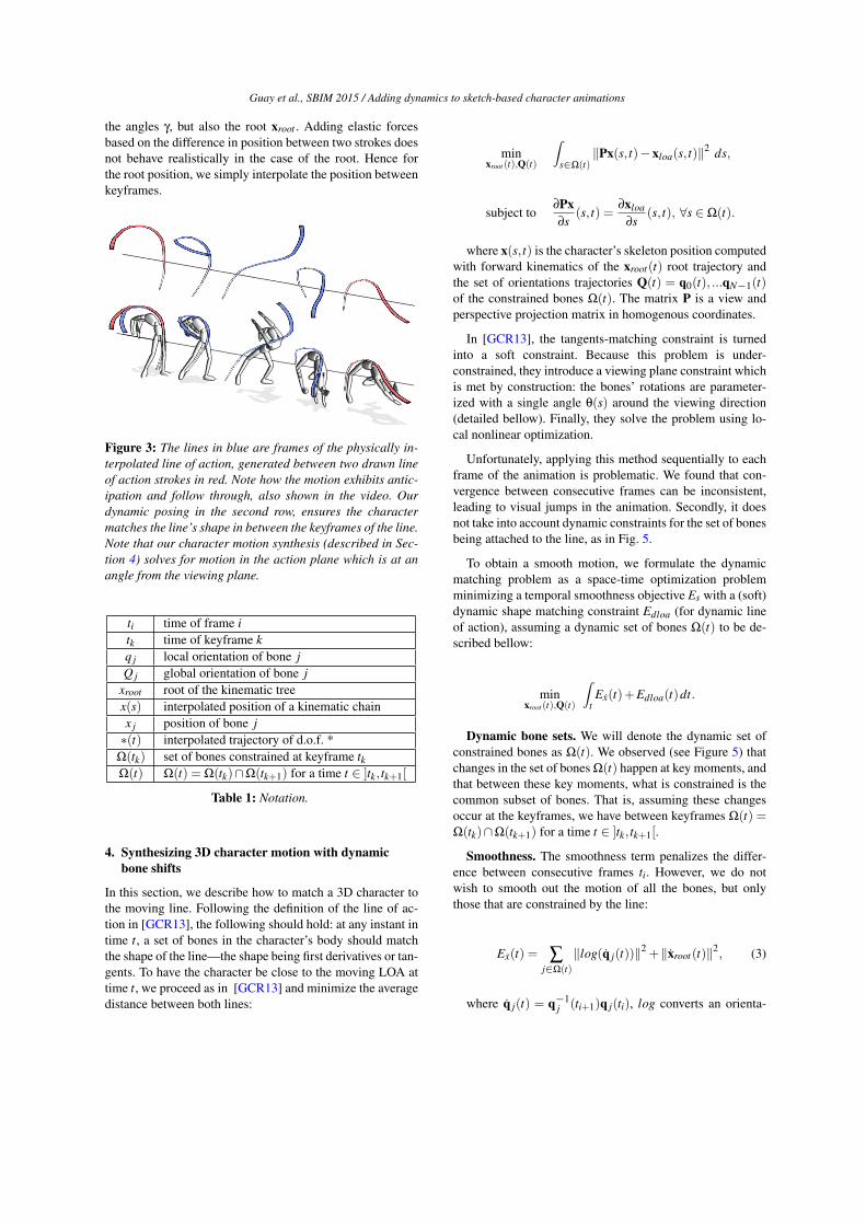
Figure 3: The lines in blue are frames of the physically in-terpolated line of action, generated between two drawn lineof action strokes in red. Note how the motion exhibits antic-ipation and follow through, also shown in the video. Ourdynamic posing in the second row, ensures the charactermatches the line’s shape in between the keyframes of the line.Note that our character motion synthesis (described in Sec-tion 4) solves for motion in the action plane which is at anangle from the viewing plane.
ti time of frame itk time of keyframe kq j local orientation of bone jQ j global orientation of bone j
xroot root of the kinematic treex(s) interpolated position of a kinematic chainx j position of bone j∗(t) interpolated trajectory of d.o.f. *
Ω(tk) set of bones constrained at keyframe tkΩ(t) Ω(t) = Ω(tk)∩Ω(tk+1) for a time t ∈ ]tk, tk+1[
Table 1: Notation.
4. Synthesizing 3D character motion with dynamicbone shifts
In this section, we describe how to match a 3D character tothe moving line. Following the definition of the line of ac-tion in [GCR13], the following should hold: at any instant intime t, a set of bones in the character’s body should matchthe shape of the line—the shape being first derivatives or tan-gents. To have the character be close to the moving LOA attime t, we proceed as in [GCR13] and minimize the averagedistance between both lines:
minxroot (t),Q(t)
∫s∈Ω(t)
‖Px(s, t)−xloa(s, t)‖2 ds,
subject to∂Px∂s
(s, t) =∂xloa
∂s(s, t), ∀s ∈Ω(t).
where x(s, t) is the character’s skeleton position computedwith forward kinematics of the xroot(t) root trajectory andthe set of orientations trajectories Q(t) = q0(t), ...qN−1(t)of the constrained bones Ω(t). The matrix P is a view andperspective projection matrix in homogenous coordinates.
In [GCR13], the tangents-matching constraint is turnedinto a soft constraint. Because this problem is under-constrained, they introduce a viewing plane constraint whichis met by construction: the bones’ rotations are parameter-ized with a single angle θ(s) around the viewing direction(detailed bellow). Finally, they solve the problem using lo-cal nonlinear optimization.
Unfortunately, applying this method sequentially to eachframe of the animation is problematic. We found that con-vergence between consecutive frames can be inconsistent,leading to visual jumps in the animation. Secondly, it doesnot take into account dynamic constraints for the set of bonesbeing attached to the line, as in Fig. 5.
To obtain a smooth motion, we formulate the dynamicmatching problem as a space-time optimization problemminimizing a temporal smoothness objective Es with a (soft)dynamic shape matching constraint Edloa (for dynamic lineof action), assuming a dynamic set of bones Ω(t) to be de-scribed bellow:
minxroot (t),Q(t)
∫tEx(t)+Edloa(t)dt.
Dynamic bone sets. We will denote the dynamic set ofconstrained bones as Ω(t). We observed (see Figure 5) thatchanges in the set of bones Ω(t) happen at key moments, andthat between these key moments, what is constrained is thecommon subset of bones. That is, assuming these changesoccur at the keyframes, we have between keyframes Ω(t) =Ω(tk)∩Ω(tk+1) for a time t ∈ ]tk, tk+1[.
Smoothness. The smoothness term penalizes the differ-ence between consecutive frames ti. However, we do notwish to smooth out the motion of all the bones, but onlythose that are constrained by the line:
Ex(t) = ∑j∈Ω(t)
‖log(q j(t))‖2 +‖xroot(t)‖2, (3)
where q j(t) = q−1j (ti+1)q j(ti), log converts an orienta-

Guay et al., SBIM 2015 / Adding dynamics to sketch-based character animations
Figure 4: The animator designs a fluent line motion, and different parts of the body are attached to the line as it moves. Interms of body attachments, we hypothesize that artist seeks to maximize line fulfillment, while respecting basic principles ofarticulated motion such as balance. In this paper, we take a first step and observe that transitions happen at key moments (redsquares), and that between the key moments, it is the common subset of bones from the key moments that remain constrained.Illustration from the book Cartoon Animation [Bla94], c©The Estate of Preston Blair.
tion into a 3D angle vector, and xroot(t) is the time derivativeof the root trajectory.
Shape-matching constraint is turned into a soft con-straint, resulting in the energy function:
Eloa(t) =∫
s∈Ω(t)wxEx(s, t)+w∂E∂(s, t)
Ex(s, t) = ‖Px(s, t)−xdloa(s, t)‖2
E∂(s, t) =∥∥∥∥∂Px
∂s(s, t)− ∂xdloa
∂s(s, t)
∥∥∥∥2
where s is the space that covers each constrained bones inΩ(t).
Staging and solving for motion. In [GCR13], the prob-lem is reduced by constraining the bone rotations to a singleangle, where the angle rotates the bone in the viewing direc-tion of the camera. It is true that many motions meant to bewatched do happen in a plane nearly parallel to the viewingplane. However, the staging of the animation, can be at anangle from the viewing plane. More generally, we will referto the plane in which the animation lies as the action plane,and the user is allowed to rotate it. For example, considerFig. 3 where the character’s motion lies on plane at anglefrom the viewing plane. This does not mean the skeleton isplanar, only the transformations of the joints are 1 dimen-sional and rotating around the action plane’s normal.
We solve for the angles controlling an axis-angle rotationin a direction ~n (normal to action plane), and angle θ j, forevery bone j. The bone orientation of the character is thusdefined as: q
′
j = q jexp(θ j ~n). When the problem is solved,we set the new bone orientation to the previous one q j ←
q′
j, and the angle θ j to 0. The root position is parametrized
as x′root = xroot +wu~u+wv~v where ~u and ~v are orthogonal
vectors in the plane. We optimize with respect to wu and wv,and when finished set the new value of xroot to x
′root .
The physically-based line of action will hold rich motionbetween keyframes. Solving for the character’s pose onlyat the keyframes and interpolating the configuration of thecharacter (the orientations and root) does not make the char-acter match the elastic line between keyframes. The prob-lem is that solving for several frames between the keyframesleads to inconsistencies between frames—even when usingsmoothing.
To obtain a closer match that remains smooth, we usea simple form of motion reduction: we use Hermite splineinterpolation for the trajectories and optimize over this re-duced set of degrees of freedom. We use one node for eachkeyframe stroke, and subdivide once between keyframes re-sulting in 2N − 1 nodes, where N is the number of strokekeyframes. This scheme provides the extra liberty necessaryto match the physically-based line of action, while remain-ing smooth.
Each frame is initialized with an initial pose, we solve (4)over the whole set of frames using local non-linear optimiza-tion. In the next section, we detail how to add 3D twist andcontact constraints.
4.1. Additional 3D constraints
In the previous section, we solved for a planar 3D charac-ter motion. With this approach it is quite difficult to repre-sent and control aspects of the 3D motion such as 3D twistand contacts with the environment. In this section we extendour space-time optimization framework to consider 3D con-straints for twist and contacts. This is done by adding newterms to the optimization problem (4) reflecting twist along
Guay et al., SBIM 2015 / Adding dynamics to sketch-based character animations
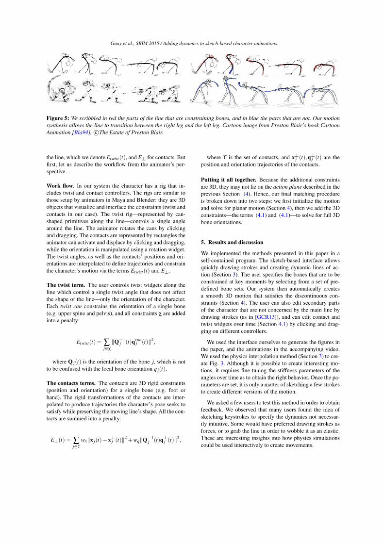
Figure 5: We scribbled in red the parts of the line that are constraining bones, and in blue the parts that are not. Our motionsynthesis allows the line to transition between the right leg and the left leg. Cartoon image from Preston Blair’s book CartoonAnimation [Bla94], c©The Estate of Preston Blair.
the line, which we denote Etwist(t), and E⊥ for contacts. Butfirst, let us describe the workflow from the animator’s per-spective.
Work flow. In our system the character has a rig that in-cludes twist and contact controllers. The rigs are similar tothose setup by animators in Maya and Blender: they are 3Dobjects that visualize and interface the constraints (twist andcontacts in our case). The twist rig—represented by can-shaped primitives along the line—controls a single anglearound the line. The animator rotates the cans by clickingand dragging. The contacts are represented by rectangles theanimator can activate and displace by clicking and dragging,while the orientation is manipulated using a rotation widget.The twist angles, as well as the contacts’ positions and ori-entations are interpolated to define trajectories and constrainthe character’s motion via the terms Etwist(t) and E⊥.
The twist term. The user controls twist widgets along theline which control a single twist angle that does not affectthe shape of the line—only the orientation of the character.Each twist can constrains the orientation of a single bone(e.g. upper spine and pelvis), and all constraints χ are addedinto a penalty:
Etwist(t) = ∑j∈χ
‖Q−1j (t)qcan
j (t)‖2,
where Q j(t) is the orientation of the bone j, which is notto be confused with the local bone orientation q j(t).
The contacts terms. The contacts are 3D rigid constraints(position and orientation) for a single bone (e.g. foot orhand). The rigid transformations of the contacts are inter-polated to produce trajectories the character’s pose seeks tosatisfy while preserving the moving line’s shape. All the con-tacts are summed into a penalty:
E⊥(t) = ∑j∈ϒ
wx‖x j(t)−x⊥j (t)‖2 +wq‖Q−1j (t)q⊥j (t)‖2,
where ϒ is the set of contacts, and x⊥j (t),q⊥j (t) are the
position and orientation trajectories of the contacts.
Putting it all together. Because the additional constraintsare 3D, they may not lie on the action plane described in theprevious Section (4). Hence, our final matching procedureis broken down into two steps: we first initialize the motionand solve for planar motion (Section 4), then we add the 3Dconstraints—the terms (4.1) and (4.1)—to solve for full 3Dbone orientations.
5. Results and discussion
We implemented the methods presented in this paper in aself-contained program. The sketch-based interface allowsquickly drawing strokes and creating dynamic lines of ac-tion (Section 3). The user specifies the bones that are to beconstrained at key moments by selecting from a set of pre-defined bone sets. Our system then automatically createsa smooth 3D motion that satisfies the discontinuous con-straints (Section 4). The user can also edit secondary partsof the character that are not concerned by the main line bydrawing strokes (as in [GCR13]), and can edit contact andtwist widgets over time (Section 4.1) by clicking and drag-ging on different controllers.
We used the interface ourselves to generate the figures inthe paper, and the animations in the accompanying video.We used the physics interpolation method (Section 3) to cre-ate Fig. 3. Although it is possible to create interesting mo-tions, it requires fine tuning the stiffness parameters of theangles over time as to obtain the right behavior. Once the pa-rameters are set, it is only a matter of sketching a few strokesto create different versions of the motion.
We asked a few users to test this method in order to obtainfeedback. We observed that many users found the idea ofsketching keystrokes to specify the dynamics not necessar-ily intuitive. Some would have preferred drawing strokes asforces, or to grab the line in order to wobble it as an elastic.These are interesting insights into how physics simulationscould be used interactively to create movements.

Guay et al., SBIM 2015 / Adding dynamics to sketch-based character animations
Figure 6: The backwalk in gymnastics is an example of a motion that holds a continuous line of action throughout the animation.The first pose in this figure has the right leg constrained, then the left leg for the 3 subsequent poses, and finally the right legagain at the last pose.
We then tested our method to deal with dynamic boneconstraints (Section 4). Note that in these results, the line’smotion was produced with basic geometric interpolation ofthe strokes. The animation in Fig.5 requires setting a set ofbones at a first key moment for the right leg, and setting asecond set of bones—holding the right leg—at an other keymoment. In our implementation, the user selects the bodyparts from a set of pre-defined bone sets by scribbling astroke over a set of bones. For the moment, it does not al-low re-producing the long sequence in Fig. 4, where individ-ual bones lie in the middle of the stroke. We used the sameprocedure to create Fig. 6—which transitions from the rightleg, to the left leg, and back to the left leg. Note that a fewadditional results in the video show these capacities, whilesatisfying 3D contact constraints (Section 4.1).
Limitations and future work
We explored the idea of using a physically-simulated line ofaction that would mimic the action of the character’s internalforces. Our experiments showed it could produce desirablefeatures such as anticipation and follow-through. However,we found that different users could expect different “behav-iors” for the line, and we observed that fine tuning the stiff-ness parameters over time to obtain a given behavior wasquite long. We think this area could be improved with sometraining of the parameters, perhaps from cartoon videos.
While our method allows squashing and stretching thestrokes, our 3D motion synthesis algorithm based on[GCR13] solves only for piecewise rigid motion, and there-fore, does not allow squashing and stretching the character.Additionally, the solver requires a fair amount of smooth-ing, realized by adding a smoothness term, and represent-ing the motion with a low-dimensional spline interpola-tion scheme—which in consequence, prevents from an exactmatch between the character and the line. Recently an ex-act algorithm that support squash and stretch is introducedin [GRGC15].
We made a first step towards allowing dynamic transitionsbetween body parts fulfilling the line over time. For the mo-ment, the user specifies the constraints at key moments, but
we foresee a future where these transitions could be inferredautomatically. For instance, we could have approached theproblem from a different direction: by using a controller fora physically-simulated 3D character, and adding the line’sshape matching as an additional objective as to provide thecharacter with an aesthetically pleasing line whenever pos-sible. Information from the character’s 3D dynamics, suchas balance and foot placements could be used to determinewhen the legs should join or depart from the line.
We demonstrated our concept only with articulated hu-manoid characters. Our methods should apply to other mor-phologies such as quadrupeds. In the future, it would be in-tersecting to investigate ways of fulfilling the motion withmore abstract matters—such as fluids—that dynamicallychange topology.
Conclusion
By viewing the line of action as an elastic, the animator cancreate energetic movements for 3D character by sketchingstrokes. To realize this, we provide a 3D motion synthesisprocedure that supports smoothly changing body parts thatare being driven by the elastic line over time. While thephysically-based interpolation method requires fine-tuningstiffness parameters, we were able to reproduce cartoon mo-tions. In particular, we demonstrated its effectiveness forproducing anticipation and follow-through. Future work willfurther investigate other animation principles, and interac-tions with the environment.
Ackowledgements
We thank Estelle Charleroy for help with video editingand Deidre Stuffer with text editing. We also thank theanonymous reviewers for their useful comments and sugges-tions. This work was partially funded by the ERC advancedgrant no. 291184 EXPRESSIVE from the European ResearchCouncil (ERC-2011-ADG 20110209) and NSF award NRI-1208632.
Guay et al., SBIM 2015 / Adding dynamics to sketch-based character animations
References[Bla94] BLAIR P.: Cartoon Animation. Walter Foster, 1994. 3, 5,
6
[CYI∗12] CHOI M. G., YANG K., IGARASHI T., MITANI J.,LEE J.: Retrieval and visualization of human motion data viastick figures. Computer Graphics Forum 31, 7 (2012), 2057–2065. 2
[DIC∗03] DAVIS J., IGARASHI M., CHUANG E., POPOVIC’ Z.,SALESIN D.: A sketching interface for articulated figure anima-tion. In Proceedings of the 2003 ACM SIGGRAPH/Eurographicssymposium on Computer animation (2003), SCA ’03, pp. 320–328. 2
[GCR13] GUAY M., CANI M.-P., RONFARD R.: The line of ac-tion: an intuitive interface for expressive character posing. ACMTransactions on Graphics 32, 6 (2013). 2, 4, 5, 6, 7
[GRGC15] GUAY M., RONFARD R., GLEICHER M., CANI M.-P.: Space-time sketching of character animation. ACM Transac-tions on Graphics (2015). 7
[HWBO95] HODGINS J. K., WOOTEN W. L., BROGAN D. C.,O’BRIEN J. F.: Animating human athletics. In Proceedings ofthe 22Nd Annual Conference on Computer Graphics and Inter-active Techniques (1995), SIGGRAPH ’95, pp. 71–78. 2, 3
[KG05] KHO Y., GARLAND M.: Sketching mesh deformations.In Proceedings of the 2005 Symposium on Interactive 3D Graph-ics and Games (2005), I3D ’05, pp. 147–154. 2
[Las87] LASSETER J.: Principals of traditional animation appliedto 3d computer animation. ACM SIGGRAPH Computer Graphics21, 4 (1987), 35–44. 2
[LIMS10] LIN J., IGARASHI T., MITANI J., SAUL G.: A sketch-ing interface for sitting-pose design. In Proceedings of the Sev-enth Sketch-Based Interfaces and Modeling Symposium (2010),SBIM ’10, pp. 111–118. 2
[NF03] NEFF M., FIUME E.: Aesthetic edits for character anima-tion. In Proceedings of the 2003 ACM SIGGRAPH/EurographicsSymposium on Computer Animation (2003), SCA ’03, pp. 239–244. 2
[OBP∗13] ÖZTIRELI A. C., BARAN I., POPA T., DALSTEINB., SUMNER R. W., GROSS M.: Differential blending for ex-pressive sketch-based posing. In Proceedings of the 2013 ACMSIGGRAPH/Eurographics Symposium on Computer Animation(2013), SCA ’13, pp. 155–164. 2
[SG92] SEDERBERG T. W., GREENWOOD E.: A physicallybased approach to 2–d shape blending. SIGGRAPH Com-put. Graph. 26, 2 (1992), 25–34. 3
[Tay00] TAYLOR C. J.: Reconstruction of articulated objectsfrom point correspondences in a single uncalibrated image. Com-put. Vis. Image Underst. 80, 3 (2000), 349–363. 2
[TPBF87] TERZOPOULOS D., PLATT J., BARR A., FLEISCHERK.: Elastically deformable models. SIGGRAPH Comput. Graph.21, 4 (1987), 205–214. 2
[WC11] WEI X., CHAI J.: Intuitive interactive human-characterposing with millions of example poses. IEEE Comput. Graph.Appl. 31, 4 (2011), 78–88. 2