Adding and Dropping Nodes in Unidirectional Path Switched ... · PDF fileAdding and Dropping...
16
Adding and Dropping Nodes in Unidirectional Path Switched Rings Document ID: 18480 Contents Introduction Prerequisites Requirements Components Used Background Information Conventions How to Add a Node to the UPSR Check Circuit Integrity Initiate a Forced Protection Switch Connect Fibers to the New Node Re-launch CTC Update Circuits Release the Protection Switch How to Remove a Node From the UPSR Delete Circuits Dropped at the Node Being Removed Related Information Introduction This document describes how to add and remove a 15454 node in a Unidirectional Path Switched Ring (UPSR). With the use of a fully documented lab setup with detailed explanations, the document walks the reader through the steps necessary to first add and then remove a node in a UPSR Prerequisites Requirements There are no specific prerequisites for this document. Components Used This document is not restricted to specific software and hardware versions. Background Information This document uses a sample lab setup with three nodes (Node1, Node2 and Node3) in order to demonstrate how to add and then remove a fourth node (Node4) between Node1 and Node3. This network diagram shows the setup used here:
Transcript of Adding and Dropping Nodes in Unidirectional Path Switched ... · PDF fileAdding and Dropping...
Adding and Dropping Nodes in Unidirectional PathSwitched Rings
Document ID: 18480
Contents
Introduction Prerequisites Requirements Components Used Background Information Conventions How to Add a Node to the UPSR Check Circuit Integrity Initiate a Forced Protection Switch Connect Fibers to the New Node Re−launch CTC Update Circuits Release the Protection Switch How to Remove a Node From the UPSR Delete Circuits Dropped at the Node Being Removed Related Information
Introduction
This document describes how to add and remove a 15454 node in a Unidirectional Path Switched Ring(UPSR). With the use of a fully documented lab setup with detailed explanations, the document walks thereader through the steps necessary to first add and then remove a node in a UPSR
Prerequisites
Requirements
There are no specific prerequisites for this document.
Components Used
This document is not restricted to specific software and hardware versions.
Background Information
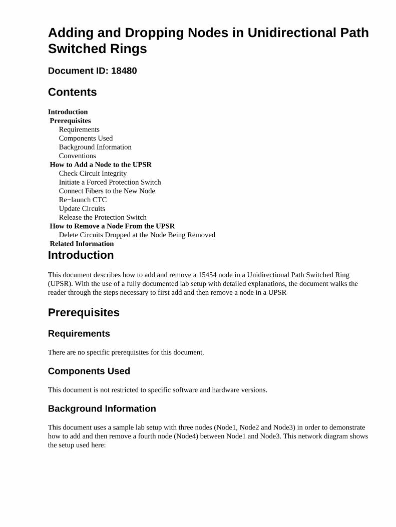
This document uses a sample lab setup with three nodes (Node1, Node2 and Node3) in order to demonstratehow to add and then remove a fourth node (Node4) between Node1 and Node3. This network diagram showsthe setup used here:
In this document, it is assumed that the new node is racked and powered up with all of its cards installed andtheir provisioning completed. Provisioning includes:
General• Network• Timing• SONET Data Communications Channels (SDCCs)• Place the optical ports in service•
References for the previous tasks can be found in the Setting Up a UPSR section of the Cisco ONS 15454Procedure Guide, Release 3.4. Be sure to run test traffic through the new node in order to verify that allhardware is operational. Do this prior to the start of the procedure. You should also identify and tag all fibersinvolved before you begin.
Note: You can only add one node to a UPSR at a time.
Caution: The procedures to add a node and remove a node are service−affecting and should be
performed during a maintenance window due to the protection switching involved. Disruptions of traffic up tothree minutes are possible for any Ethernet traffic due to Spanning Tree re−convergence. All other trafficendures up to a 50 ms hit. In addition, the procedure to remove a node causes each circuit that changedSynchronous Transport Signal (STS) or Virtual Tributary (VT) while it passes through the removed node inorder to incur an outage for the length of time that it takes to delete and rebuild. This depends on operatorproficiency with Cisco Transport Controller (CTC).
Conventions
Refer to Cisco Technical Tips Conventions for more information on document conventions.
How to Add a Node to the UPSR
This procedure involves you to:
Check circuit integrity.• Initiate a forced protection switch.• Connect fibers to the new node.• Re−launch CTC.• Update circuits.•
Release the forced protection switch.•
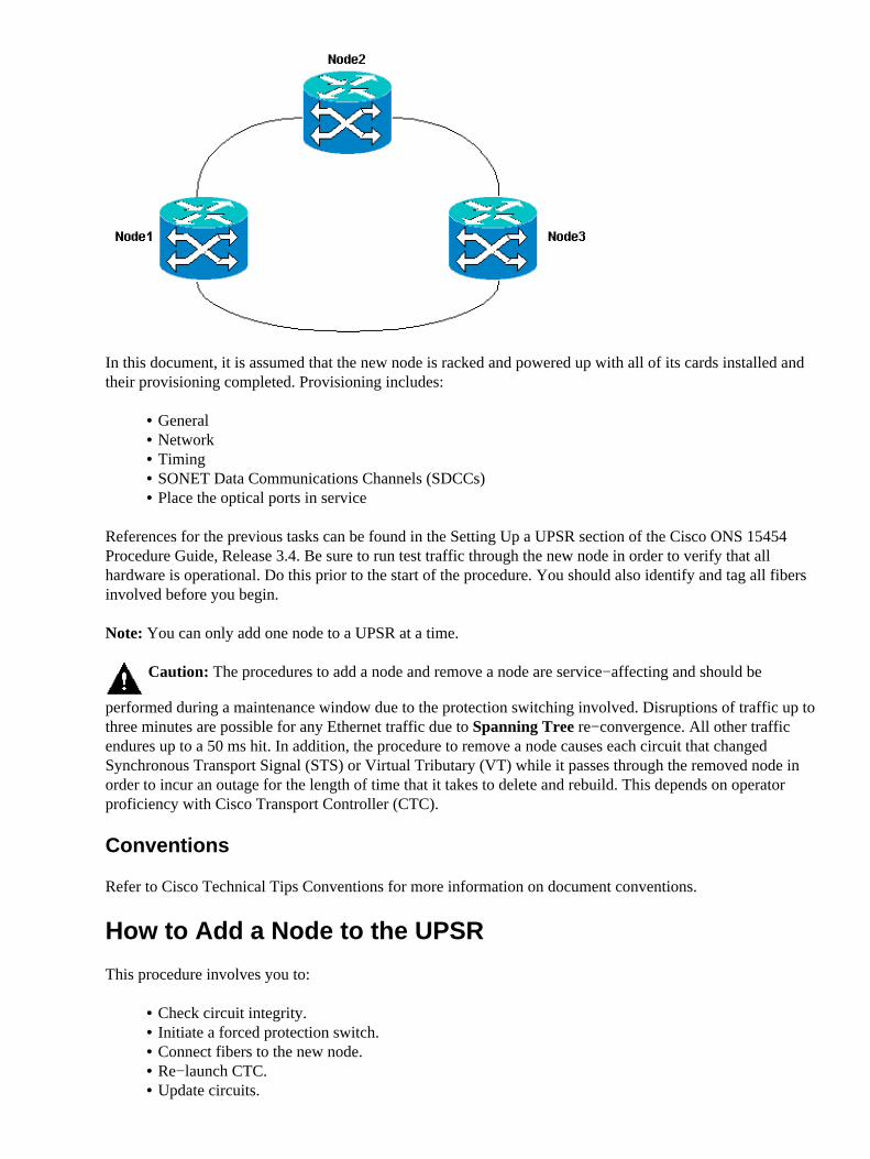
This is the UPSR ring topology in the lab setup as seen from the CTC network view:
Check Circuit Integrity
Complete the steps in the instructions provided in order to check the circuit integrity:
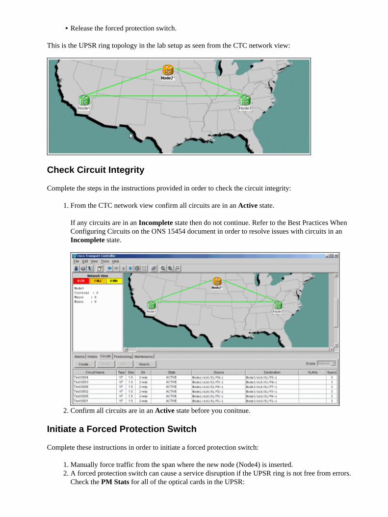
From the CTC network view confirm all circuits are in an Active state.
If any circuits are in an Incomplete state then do not continue. Refer to the Best Practices WhenConfiguring Circuits on the ONS 15454 document in order to resolve issues with circuits in anIncomplete state.
1.
Confirm all circuits are in an Active state before you conitnue.2.
Initiate a Forced Protection Switch
Complete these instructions in order to initiate a forced protection switch:
Manually force traffic from the span where the new node (Node4) is inserted.1. A forced protection switch can cause a service disruption if the UPSR ring is not free from errors.Check the PM Stats for all of the optical cards in the UPSR:
2.
Log into each shelf in the ring.a. Click on each UPSR optical card.b. Choose Performance.c. Click Refresh.d. Verify that all fields contain zero values.e.
If you see zero values in all fields, then the span runs free of errors.
Caution: Traffic is unprotected during a forced protection switch.
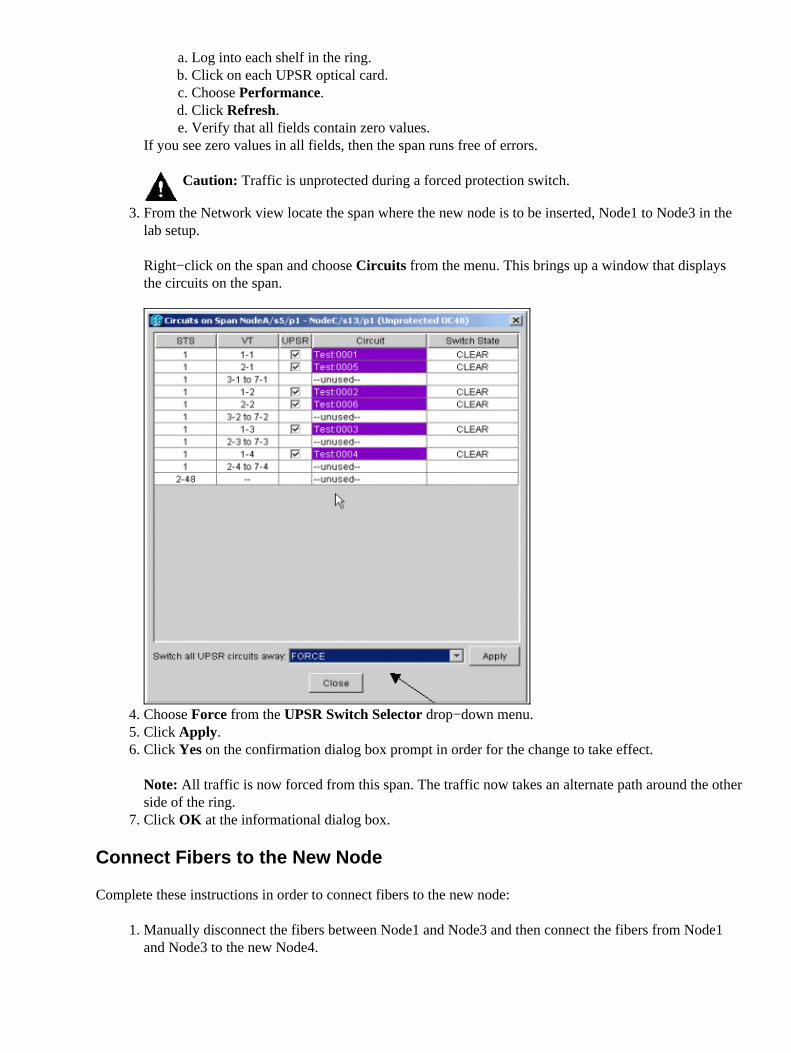
From the Network view locate the span where the new node is to be inserted, Node1 to Node3 in thelab setup.
Right−click on the span and choose Circuits from the menu. This brings up a window that displaysthe circuits on the span.
3.
Choose Force from the UPSR Switch Selector drop−down menu.4. Click Apply.5. Click Yes on the confirmation dialog box prompt in order for the change to take effect.
Note: All traffic is now forced from this span. The traffic now takes an alternate path around the otherside of the ring.
6.
Click OK at the informational dialog box.7.
Connect Fibers to the New Node
Complete these instructions in order to connect fibers to the new node:
Manually disconnect the fibers between Node1 and Node3 and then connect the fibers from Node1and Node3 to the new Node4.
1.
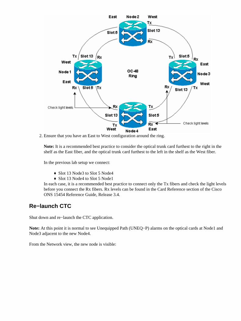
Ensure that you have an East to West configuration around the ring.
Note: It is a recommended best practice to consider the optical trunk card furthest to the right in theshelf as the East fiber, and the optical trunk card furthest to the left in the shelf as the West fiber.
In the previous lab setup we connect:
Slot 13 Node3 to Slot 5 Node4♦ Slot 13 Node4 to Slot 5 Node1♦
In each case, it is a recommended best practice to connect only the Tx fibers and check the light levelsbefore you connect the Rx fibers. Rx levels can be found in the Card Reference section of the CiscoONS 15454 Reference Guide, Release 3.4.
2.
Re−launch CTC
Shut down and re−launch the CTC application.
Note: At this point it is normal to see Unequipped Path (UNEQ−P) alarms on the optical cards at Node1 andNode3 adjacent to the new Node4.
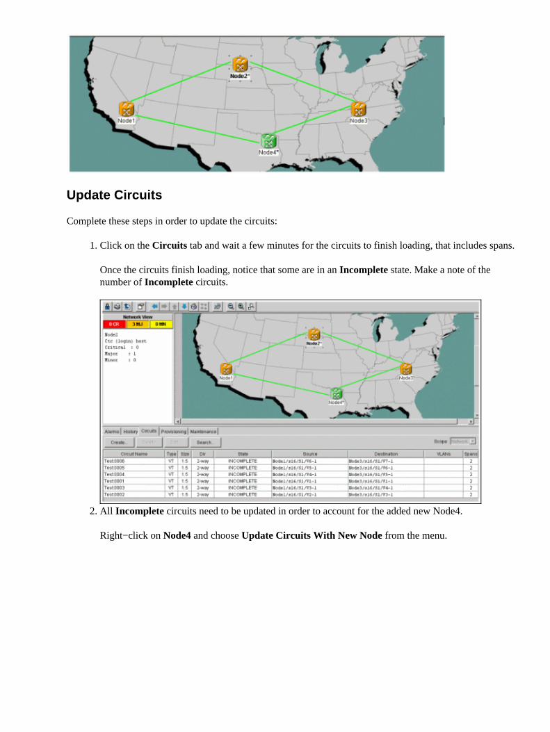
From the Network view, the new node is visible:
Update Circuits
Complete these steps in order to update the circuits:
Click on the Circuits tab and wait a few minutes for the circuits to finish loading, that includes spans.
Once the circuits finish loading, notice that some are in an Incomplete state. Make a note of thenumber of Incomplete circuits.
1.
All Incomplete circuits need to be updated in order to account for the added new Node4.
Right−click on Node4 and choose Update Circuits With New Node from the menu.
2.

A dialog box appears, which indicates that circuits are updated.
The circuits become Active one at a time.
3.
When all circuits are updated, a confirmation dialog box appears, which indicates the number ofcircuits updated.
This number should match the number of Incomplete circuits noted in step 1. At this point all circuitsshould be Active.
4.
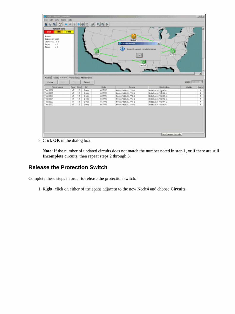
Click OK in the dialog box.
Note: If the number of updated circuits does not match the number noted in step 1, or if there are stillIncomplete circuits, then repeat steps 2 through 5.
5.
Release the Protection Switch
Complete these steps in order to release the protection switch:
Right−click on either of the spans adjacent to the new Node4 and choose Circuits.1.
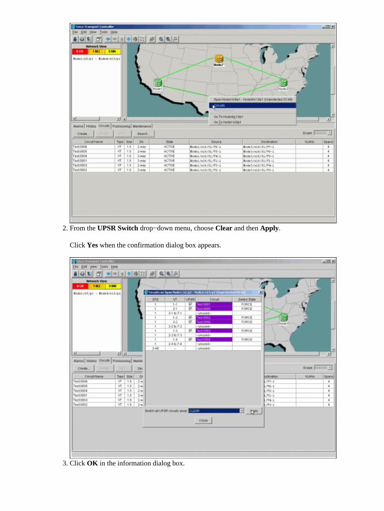
From the UPSR Switch drop−down menu, choose Clear and then Apply.
Click Yes when the confirmation dialog box appears.
2.
Click OK in the information dialog box.3.
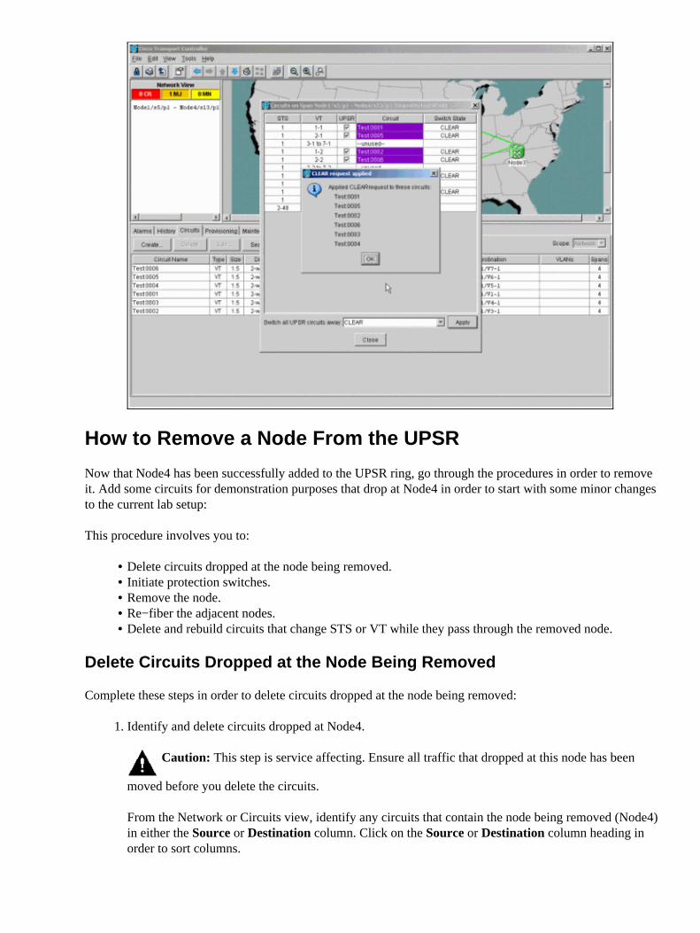
How to Remove a Node From the UPSR
Now that Node4 has been successfully added to the UPSR ring, go through the procedures in order to removeit. Add some circuits for demonstration purposes that drop at Node4 in order to start with some minor changesto the current lab setup:
This procedure involves you to:
Delete circuits dropped at the node being removed.• Initiate protection switches.• Remove the node.• Re−fiber the adjacent nodes.• Delete and rebuild circuits that change STS or VT while they pass through the removed node.•
Delete Circuits Dropped at the Node Being Removed
Complete these steps in order to delete circuits dropped at the node being removed:
Identify and delete circuits dropped at Node4.
Caution: This step is service affecting. Ensure all traffic that dropped at this node has been
moved before you delete the circuits.
From the Network or Circuits view, identify any circuits that contain the node being removed (Node4)in either the Source or Destination column. Click on the Source or Destination column heading inorder to sort columns.
1.
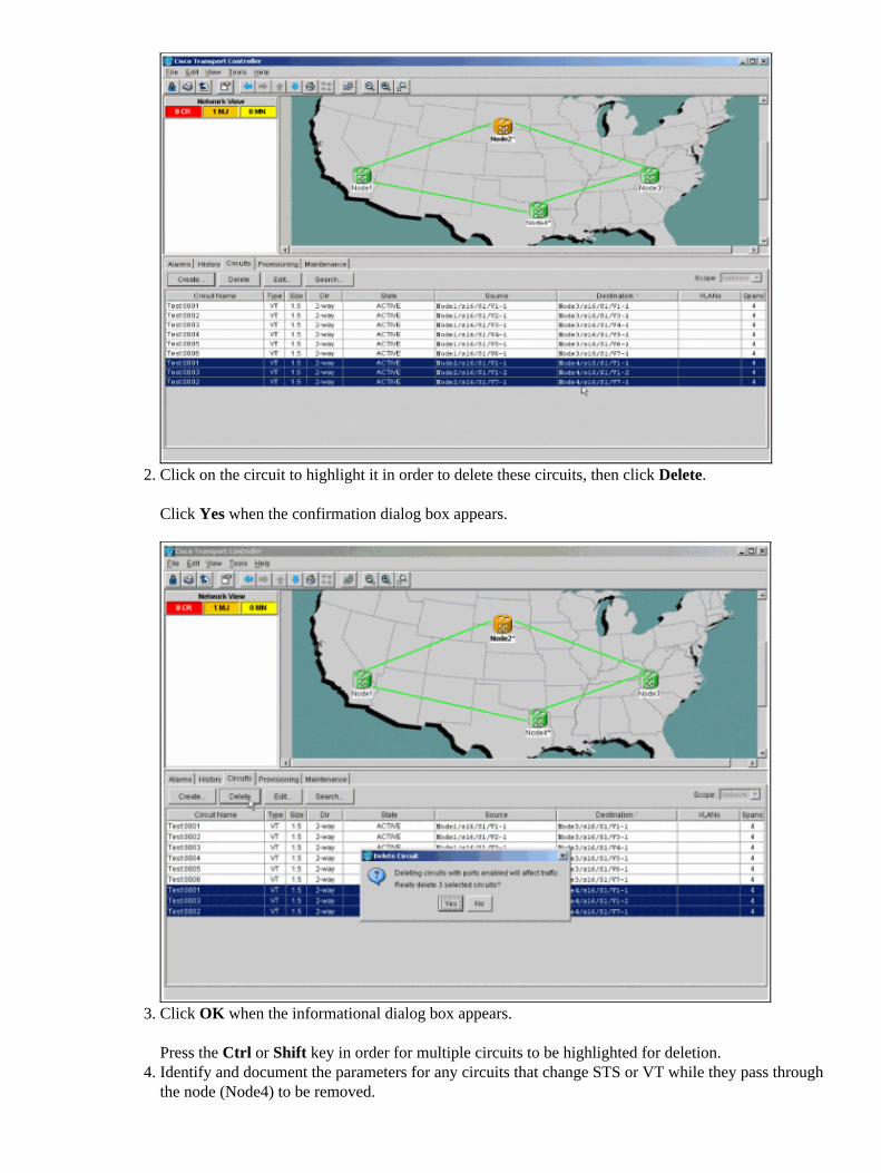
Click on the circuit to highlight it in order to delete these circuits, then click Delete.
Click Yes when the confirmation dialog box appears.
2.
Click OK when the informational dialog box appears.
Press the Ctrl or Shift key in order for multiple circuits to be highlighted for deletion.
3.
Identify and document the parameters for any circuits that change STS or VT while they pass throughthe node (Node4) to be removed.
4.
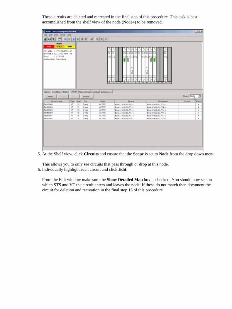
These circuits are deleted and recreated in the final step of this procedure. This task is bestaccomplished from the shelf view of the node (Node4) to be removed.
At the Shelf view, click Circuits and ensure that the Scope is set to Node from the drop down menu.
This allows you to only see circuits that pass through or drop at this node.
5.
Individually highlight each circuit and click Edit.
From the Edit window make sure the Show Detailed Map box is checked. You should now see onwhich STS and VT the circuit enters and leaves the node. If these do not match then document thecircuit for deletion and recreation in the final step 15 of this procedure.
6.
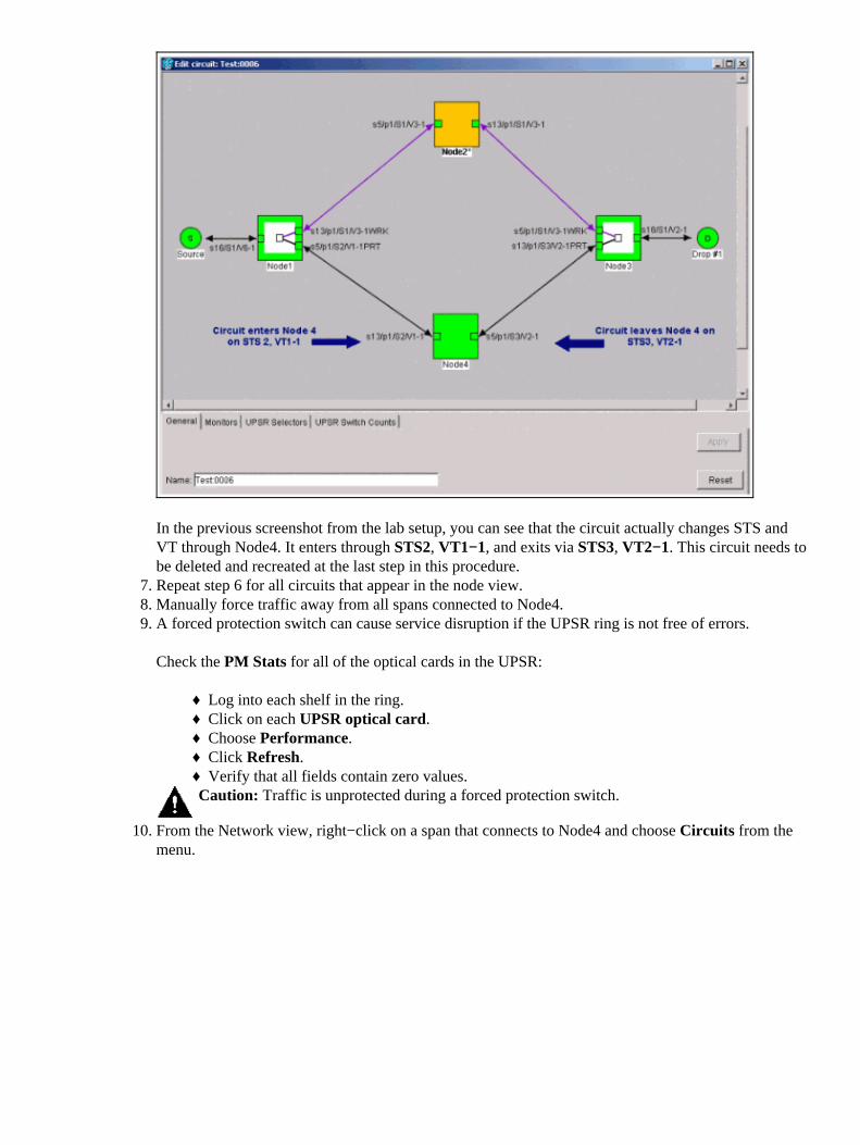
In the previous screenshot from the lab setup, you can see that the circuit actually changes STS andVT through Node4. It enters through STS2, VT1−1, and exits via STS3, VT2−1. This circuit needs tobe deleted and recreated at the last step in this procedure.Repeat step 6 for all circuits that appear in the node view.7. Manually force traffic away from all spans connected to Node4.8. A forced protection switch can cause service disruption if the UPSR ring is not free of errors.
Check the PM Stats for all of the optical cards in the UPSR:
Log into each shelf in the ring.♦ Click on each UPSR optical card.♦ Choose Performance.♦ Click Refresh.♦ Verify that all fields contain zero values.♦
Caution: Traffic is unprotected during a forced protection switch.
9.
From the Network view, right−click on a span that connects to Node4 and choose Circuits from themenu.
10.
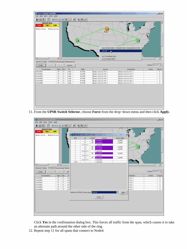
From the UPSR Switch Selector, choose Force from the drop−down menu and then click Apply.
Click Yes in the confirmation dialog box. This forces all traffic from the span, which causes it to takean alternate path around the other side of the ring.
11.
Repeat step 11 for all spans that connect to Node4.12.
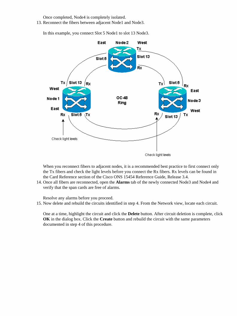
Once completed, Node4 is completely isolated.Reconnect the fibers between adjacent Node1 and Node3.
In this example, you connect Slot 5 Node1 to slot 13 Node3.
When you reconnect fibers to adjacent nodes, it is a recommended best practice to first connect onlythe Tx fibers and check the light levels before you connect the Rx fibers. Rx levels can be found inthe Card Reference section of the Cisco ONS 15454 Reference Guide, Release 3.4.
13.
Once all fibers are reconnected, open the Alarms tab of the newly connected Node3 and Node4 andverify that the span cards are free of alarms.
Resolve any alarms before you proceed.
14.
Now delete and rebuild the circuits identified in step 4. From the Network view, locate each circuit.
One at a time, highlight the circuit and click the Delete button. After circuit deletion is complete, clickOK in the dialog box. Click the Create button and rebuild the circuit with the same parametersdocumented in step 4 of this procedure.
15.

Related Information
Best Practices When Configuring Circuits on the ONS 15454• Technical Support & Documentation − Cisco Systems•
Contacts & Feedback | Help | Site Map© 2014 − 2015 Cisco Systems, Inc. All rights reserved. Terms & Conditions | Privacy Statement | Cookie Policy | Trademarks ofCisco Systems, Inc.
Updated: Nov 12, 2006 Document ID: 18480