Addendum to CEPT Report 159: Technical Considerations … · Addendum to CEPT Report 159: Technical...
27
© 2011 – Excentis – Commissioned by UPC Addendum to CEPT Report 159: Technical Considerations On The Protection Of Cable Services Distribution: public Our reference: P11255 Version: 1.0, December 6 th 2011
-
Upload
truongcong -
Category
Documents
-
view
224 -
download
2
Transcript of Addendum to CEPT Report 159: Technical Considerations … · Addendum to CEPT Report 159: Technical...
© 2011 – Excentis – Commissioned by UPC
Addendum to CEPT Report 159:
Technical Considerations On The Protection Of Cable Services
Distribution: public Our reference: P11255 Version: 1.0, December 6th 2011
Addendum to CEPT Report 159 page 2/27
© 2011 – Excentis - Commissioned by UPC Broadband
Table of contents
Table of contents ................................................................................................... 2
Summary .............................................................................................................. 3
1 Cable network architecture characteristics ................................................................. 3
1.1 RF spectrum usage ....................................................................................... 4
1.1.1 Analogue television .................................................................................. 5
1.1.2 Digital Television ..................................................................................... 5
1.1.3 Internet (EuroDOCSIS) ............................................................................ 6
1.1.4 Telephony .............................................................................................. 6
1.2 Signal characteristics and protection criteria ........................................................ 7
1.2.1 Protection analogue TV signals as per EN 60728-1 ...................................... 7
1.2.2 Protection digital television signals (DVB-C) as per EN60728-1 ..................... 8
1.2.3 Protection digital signals (DVB-C as used for EuroDOCSIS) .......................... 9
1.2.4 Important remarks on signal characteristics .................................................. 10
2 WSD Emission limits .......................................................................................... 11
2.1 General calculation of maximum WSD interference on CATV systems .................... 12
2.1.1 Methodology for calculation of WSD interference .......................................... 14
2.1.2 Determination of shielding effectiveness ...................................................... 16
2.1.2.1 Passive cable equipment shielding effectiveness........................................ 16
2.1.2.2 Coaxial cable shielding effectiveness ...................................................... 17
2.1.2.3 Device shielding effectiveness ............................................................... 17
2.1.2.4 System shielding effectiveness – [PG ESKM] workgroup ........................... 17
2.1.3 Resulting WSD interference on cable system ............................................... 18
2.1.3.1 Case I: Typical Rx level vs. Shielding effectiveness ............................... 18
2.1.3.2 Case II: High shielding v.s. Receive level .............................................. 19
2.1.3.3 Case III: Worst shielding and best coupling v.s. Receive level ................... 20
2.1.4 Remarks on WSD bandwidth ................................................................... 21
2.2 Experimental evidence of interference .............................................................. 21
2.2.1 Carl-T Jones Corporation, TVBD direct pickup interference tests, 2009 ........... 22
Addendum to CEPT Report 159 page 3/27
© 2011 – Excentis - Commissioned by UPC Broadband
2.2.2 LTE interference test, Kolberg Germany, December 2009 .............................. 23
2.3 WSD EIRP limits ........................................................................................ 25
Summary
This document contains the technical basis for an amendment to CEPT Report 159 which by itself is silent on the protection of European cable based systems (PAL/SECAM, DVB-C, Euro-DOCSIS).
Harmful interference from (White Space Device) WSDs on cable systems can be characterised by three types of interference. The first interference exists between the WSD and the coaxial part of the HFC network (both in-home and external). The second type of interference is defined between a WSD and a remote cable headend receiver. A third type of interference is the interference from the WSD on a cable device itself (cable-modem, settopbox, digital cable television receivers, ... ).
This document bundles the technical argumentation for the first and third type of interference, the direct pick-up (PDU) of WSD signals by the coaxial part of cable-television systems and EMI on cable devices. During the argumentation WSD interference is considered on the end-to-end system, both on coaxial cable and on the end device itself.
Example calculations and referenced measurement data show that if ad-hoc WSDs would be operating at EIRPs of 20 to 23 dBm they will cause severe and unacceptable interference (loss of service) in many households.
Reducing their maximum EIRP to 10 dBm would still prohibit users to adjust the WSD position as to minimise/eliminate interference since interference distance is still considerable.
Should a 5 dBm EIRP be used then users would most likely be able to adjust the WSD position to minimise/eliminate the disturbance.
1 Cable network architecture characteristics
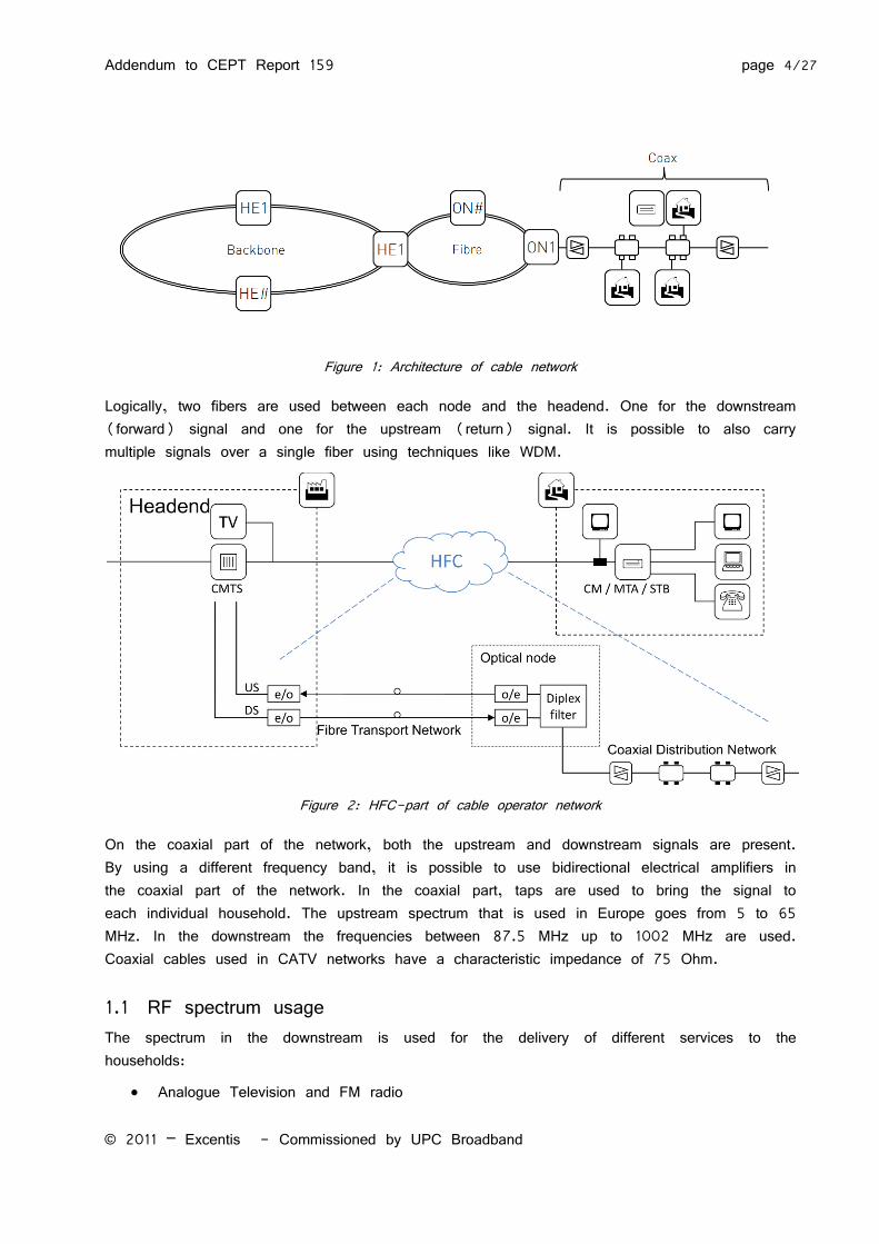
The architecture of an HFC network is shown in Figure 1. A digital backbone is used to bring the different signals to the headends (HE in the figure). From each headend fibers are used to connect to the different optical nodes in the field. The part between the headend and optical node is shown in more detail in Figure 2.
Addendum to CEPT Report 159 page 4/27
© 2011 – Excentis - Commissioned by UPC Broadband
Figure 1: Architecture of cable network
Logically, two fibers are used between each node and the headend. One for the downstream (forward) signal and one for the upstream (return) signal. It is possible to also carry multiple signals over a single fiber using techniques like WDM.
Figure 2: HFC-part of cable operator network
On the coaxial part of the network, both the upstream and downstream signals are present. By using a different frequency band, it is possible to use bidirectional electrical amplifiers in the coaxial part of the network. In the coaxial part, taps are used to bring the signal to each individual household. The upstream spectrum that is used in Europe goes from 5 to 65 MHz. In the downstream the frequencies between 87.5 MHz up to 1002 MHz are used. Coaxial cables used in CATV networks have a characteristic impedance of 75 Ohm.
1.1 RF spectrum usage The spectrum in the downstream is used for the delivery of different services to the households:
Analogue Television and FM radio
Addendum to CEPT Report 159 page 5/27
© 2011 – Excentis - Commissioned by UPC Broadband
Digital Television (including VOD)
Internet (IP)
Telephony (runs over IP)
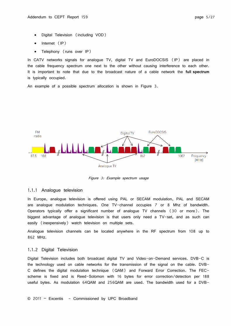
In CATV networks signals for analogue TV, digital TV and EuroDOCSIS (IP) are placed in the cable frequency spectrum one next to the other without causing interference to each other. It is important to note that due to the broadcast nature of a cable network the full spectrum is typically occupied.
An example of a possible spectrum allocation is shown in Figure 3.
Figure 3: Example spectrum usage
1.1.1 Analogue television
In Europe, analogue television is offered using PAL or SECAM modulation, PAL and SECAM are analogue modulation techniques. One TV-channel occupies 7 or 8 Mhz of bandwidth. Operators typically offer a significant number of analogue TV channels (30 or more). The biggest advantage of analogue television is that users only need a TV-set, and as such can easily (inexpensively) watch television on multiple sets.
Analogue television channels can be located anywhere in the RF spectrum from 108 up to 862 MHz.
1.1.2 Digital Television Digital Television includes both broadcast digital TV and Video-on-Demand services. DVB-C is the technology used on cable networks for the transmission of the signal on the cable. DVB-C defines the digital modulation technique (QAM) and Forward Error Correction. The FEC-scheme is fixed and is Reed-Solomon with 16 bytes for error correction/detection per 188 useful bytes. As modulation 64QAM and 256QAM are used. The bandwidth used for a DVB-
Addendum to CEPT Report 159 page 6/27
© 2011 – Excentis - Commissioned by UPC Broadband
C signal is 8 MHz. This corresponds to a raw bitrate of about 42 Mbit/s for 64QAM and about 56 Mbit/s for 256QAM. The DVB-C system (framing structure, channel coding and modulation) is described in the [EN 300 429] standard.
The content of this bitstream is called an MPEG2 transport stream (TS). Within such a transport stream multiple TV-channels are present, packets of the different channels are multiplexed in this stream. Each packet has an identifier (PID) that identifies to which stream it belongs. Within this stream, special packets (predefined PIDs) are used to also transport signaling information (PSI/SI) to the receivers. These packets also contains information on where other streams are located, which programs are available,...
Digital television channels can be located anywhere in the RF spectrum from 108 up to 1002 MHz.
1.1.3 Internet (EuroDOCSIS) Internet services in a cable network are provided over EuroDOCSIS technology. EuroDOCSIS uses the same modulation techniques as digital television (i.e. DVB-C with 64QAM or 256QAM). The cable modem termination system (CMTS) is the device located in the headend that generates the downstream signals and receives the upstream signals. In EuroDOCSIS one or more downstream channels (each 8 MHz) are used to transport data and signaling packets to the cable modems. Cable modems share the bandwidth of these channels. Up to EuroDOCSIS 2.0 a cable modem is only demodulating a single downstream channel of 8 MHz (note that this is still shared with other modems). With EuroDOCSIS 3.0 channel bonding is used, with this technology a single modem can use multiple (currently typically 4 to 8) downstream channels at the same time, these are of course still shared with other modems. The downstream channels are placed in the same spectrum as digital television and can be allocated anywhere in the RF spectrum from 108 MHz up to 862 MHz. EuroDOCSIS 3.0 defines the frequency space above 862 MHz and up to 1002 MHz as an option.
For the return path EuroDOCSIS uses the frequency spectrum between 5 and 65 MHz. Modems are assigned upstream channels to use by the CMTS. A single upstream channel is shared in a TDM-way by different modems, the CMTS acts as the master and controls which modem is allowed to transmit at what time.
1.1.4 Telephony Telephony in a cable network is provided over IP. As such it runs on top of EuroDOCSIS. This means that if the EuroDOCSIS system is not functional, telephony will not be functional anymore as well.
Addendum to CEPT Report 159 page 7/27
© 2011 – Excentis - Commissioned by UPC Broadband
1.2 Signal characteristics and protection criteria This section provides an overview of the signal characteristics of European CATV systems. The minimum, maximum and typical signal levels together with their required signal-to-noise ratio are determining factors when a maximum tolerated noise level is defined.
Once this noise level is reached in the band of the desired signal (which is considered 8 MHz bandwidth in this document), either as a result of background noise in the CATV network or induced by a WSD, the service will be disturbed.
The threshold levels defined in this section define a noise level which, if reached, will render the quality of the services provided to a level which is unacceptable.
1.2.1 Protection analogue TV signals as per EN 60728-1 Depending on the S/N level at the TV receiver the picture quality will degrade. For analogue TV picture quality is function of the power level in the main carrier versus the noise in the relevant bandwidth (typically called Carrier to Noise C/N), and the power level of the carrier with respect to a smallband interferer (typically called Carrier to Interference, C/I).
Operational requirements for analogue television signals are defined in [EN 60728-1].
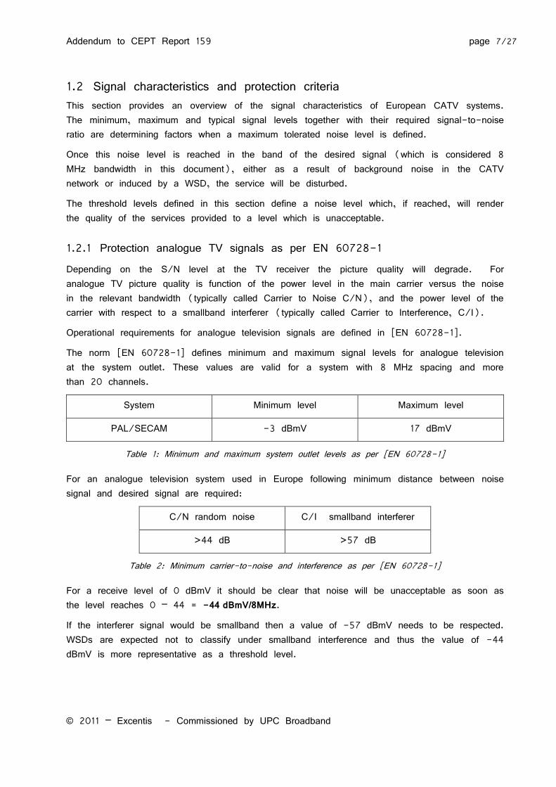
The norm [EN 60728-1] defines minimum and maximum signal levels for analogue television at the system outlet. These values are valid for a system with 8 MHz spacing and more than 20 channels.
System Minimum level Maximum level
PAL/SECAM -3 dBmV 17 dBmV
Table 1: Minimum and maximum system outlet levels as per [EN 60728-1]
For an analogue television system used in Europe following minimum distance between noise signal and desired signal are required:
C/N random noise C/I smallband interferer
>44 dB >57 dB
Table 2: Minimum carrier-to-noise and interference as per [EN 60728-1]
For a receive level of 0 dBmV it should be clear that noise will be unacceptable as soon as the level reaches 0 – 44 = -44 dBmV/8MHz.
If the interferer signal would be smallband then a value of -57 dBmV needs to be respected. WSDs are expected not to classify under smallband interference and thus the value of -44 dBmV is more representative as a threshold level.
Addendum to CEPT Report 159 page 8/27
© 2011 – Excentis - Commissioned by UPC Broadband
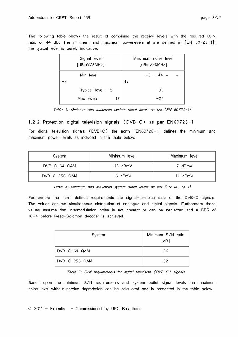
The following table shows the result of combining the receive levels with the required C/N ratio of 44 dB. The minimum and maximum powerlevels at are defined in [EN 60728-1], the typical level is purely indicative.
Signal level [dBmV/8MHz]
Maximum noise level [dBmV/8MHz]
Min level: -3
Typical level: 5
Max level: 17
-3 – 44 = -47
-39
-27
Table 3: Minimum and maximum system outlet levels as per [EN 60728-1]
1.2.2 Protection digital television signals (DVB-C) as per EN60728-1 For digital television signals (DVB-C) the norm [EN60728-1] defines the minimum and maximum power levels as included in the table below.
System Minimum level Maximum level
DVB-C 64 QAM -13 dBmV 7 dBmV
DVB-C 256 QAM -6 dBmV 14 dBmV
Table 4: Minimum and maximum system outlet levels as per [EN 60728-1]
Furthermore the norm defines requirements the signal-to-noise ratio of the DVB-C signals. The values assume simultaneous distribution of analogue and digital signals. Furthermore these values assume that intermodulation noise is not present or can be neglected and a BER of 10-4 before Reed-Solomon decoder is achieved.
System Minimum S/N ratio [dB]
DVB-C 64 QAM 26
DVB-C 256 QAM 32
Table 5: S/N requirements for digital television (DVB-C) signals
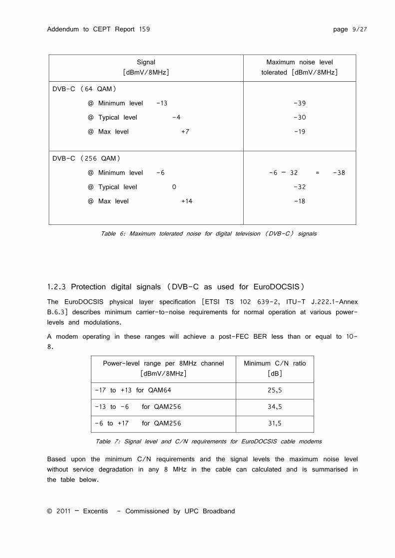
Based upon the minimum S/N requirements and system outlet signal levels the maximum noise level without service degradation can be calculated and is presented in the table below.
Addendum to CEPT Report 159 page 9/27
© 2011 – Excentis - Commissioned by UPC Broadband
Signal [dBmV/8MHz]
Maximum noise level tolerated [dBmV/8MHz]
DVB-C (64 QAM)
@ Minimum level -13
@ Typical level -4
@ Max level +7
-39
-30
-19
DVB-C (256 QAM)
@ Minimum level -6
@ Typical level 0
@ Max level +14
-6 – 32 = -38
-32
-18
Table 6: Maximum tolerated noise for digital television (DVB-C) signals
1.2.3 Protection digital signals (DVB-C as used for EuroDOCSIS) The EuroDOCSIS physical layer specification [ETSI TS 102 639-2, ITU-T J.222.1-Annex B.6.3] describes minimum carrier-to-noise requirements for normal operation at various power-levels and modulations.
A modem operating in these ranges will achieve a post-FEC BER less than or equal to 10-8.
Power-level range per 8MHz channel [dBmV/8MHz]
Minimum C/N ratio [dB]
-17 to +13 for QAM64 25,5
-13 to -6 for QAM256 34,5
-6 to +17 for QAM256 31,5
Table 7: Signal level and C/N requirements for EuroDOCSIS cable modems
Based upon the minimum C/N requirements and the signal levels the maximum noise level without service degradation in any 8 MHz in the cable can calculated and is summarised in the table below.
Addendum to CEPT Report 159 page 10/27
© 2011 – Excentis - Commissioned by UPC Broadband
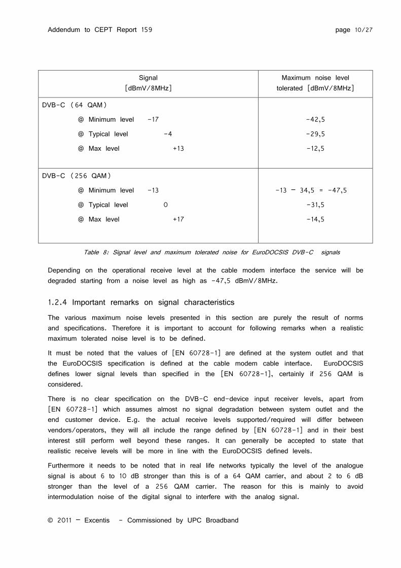
Signal [dBmV/8MHz]
Maximum noise level tolerated [dBmV/8MHz]
DVB-C (64 QAM)
@ Minimum level -17
@ Typical level -4
@ Max level +13
-42,5
-29,5
-12,5
DVB-C (256 QAM)
@ Minimum level -13
@ Typical level 0
@ Max level +17
-13 – 34,5 = -47,5
-31,5
-14,5
Table 8: Signal level and maximum tolerated noise for EuroDOCSIS DVB-C signals
Depending on the operational receive level at the cable modem interface the service will be degraded starting from a noise level as high as -47,5 dBmV/8MHz.
1.2.4 Important remarks on signal characteristics
The various maximum noise levels presented in this section are purely the result of norms and specifications. Therefore it is important to account for following remarks when a realistic maximum tolerated noise level is to be defined.
It must be noted that the values of [EN 60728-1] are defined at the system outlet and that the EuroDOCSIS specification is defined at the cable modem cable interface. EuroDOCSIS defines lower signal levels than specified in the [EN 60728-1], certainly if 256 QAM is considered.
There is no clear specification on the DVB-C end-device input receiver levels, apart from [EN 60728-1] which assumes almost no signal degradation between system outlet and the end customer device. E.g. the actual receive levels supported/required will differ between vendors/operators, they will all include the range defined by [EN 60728-1] and in their best interest still perform well beyond these ranges. It can generally be accepted to state that realistic receive levels will be more in line with the EuroDOCSIS defined levels.
Furthermore it needs to be noted that in real life networks typically the level of the analogue signal is about 6 to 10 dB stronger than this is of a 64 QAM carrier, and about 2 to 6 dB stronger than the level of a 256 QAM carrier. The reason for this is mainly to avoid intermodulation noise of the digital signal to interfere with the analog signal.
Addendum to CEPT Report 159 page 11/27
© 2011 – Excentis - Commissioned by UPC Broadband
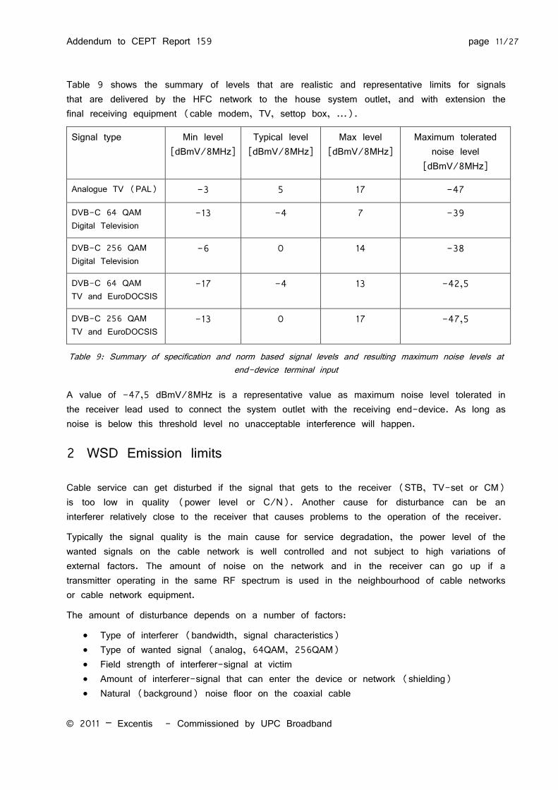
Table 9 shows the summary of levels that are realistic and representative limits for signals that are delivered by the HFC network to the house system outlet, and with extension the final receiving equipment (cable modem, TV, settop box, ...).
Signal type Min level [dBmV/8MHz]
Typical level [dBmV/8MHz]
Max level [dBmV/8MHz]
Maximum tolerated noise level
[dBmV/8MHz]
Analogue TV (PAL) -3 5 17 -47
DVB-C 64 QAM Digital Television
-13 -4 7 -39
DVB-C 256 QAM Digital Television
-6 0 14 -38
DVB-C 64 QAM TV and EuroDOCSIS
-17 -4 13 -42,5
DVB-C 256 QAM TV and EuroDOCSIS
-13 0 17 -47,5
Table 9: Summary of specification and norm based signal levels and resulting maximum noise levels at end-device terminal input
A value of -47,5 dBmV/8MHz is a representative value as maximum noise level tolerated in the receiver lead used to connect the system outlet with the receiving end-device. As long as noise is below this threshold level no unacceptable interference will happen.
2 WSD Emission limits
Cable service can get disturbed if the signal that gets to the receiver (STB, TV-set or CM) is too low in quality (power level or C/N). Another cause for disturbance can be an interferer relatively close to the receiver that causes problems to the operation of the receiver.
Typically the signal quality is the main cause for service degradation, the power level of the wanted signals on the cable network is well controlled and not subject to high variations of external factors. The amount of noise on the network and in the receiver can go up if a transmitter operating in the same RF spectrum is used in the neighbourhood of cable networks or cable network equipment.
The amount of disturbance depends on a number of factors:
Type of interferer (bandwidth, signal characteristics) Type of wanted signal (analog, 64QAM, 256QAM) Field strength of interferer-signal at victim Amount of interferer-signal that can enter the device or network (shielding) Natural (background) noise floor on the coaxial cable
Addendum to CEPT Report 159 page 12/27
© 2011 – Excentis - Commissioned by UPC Broadband
In order to estimate the WSD interference on CATV systems a calculation method is presented in the next section. The method can be used to calculate the interference of a radio system (e.g. WSD) on cable systems.
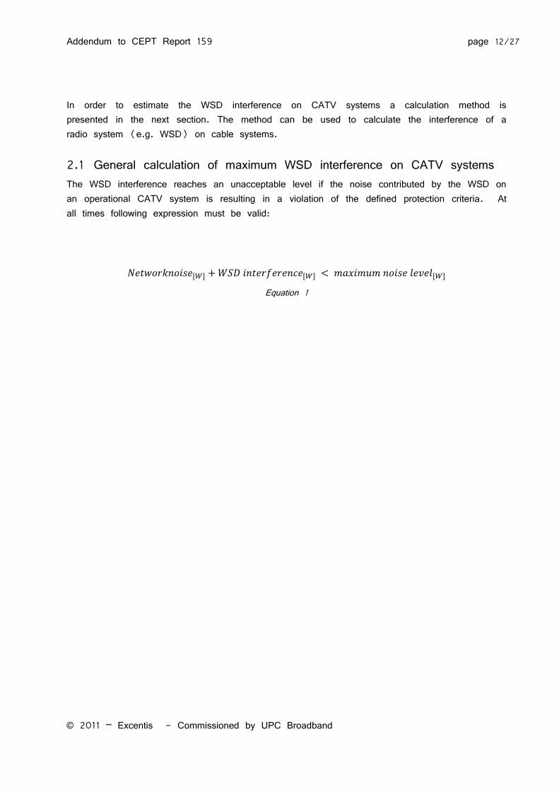
2.1 General calculation of maximum WSD interference on CATV systems The WSD interference reaches an unacceptable level if the noise contributed by the WSD on an operational CATV system is resulting in a violation of the defined protection criteria. At all times following expression must be valid:
Equation 1
Addendum to CEPT Report 159 page 13/27
© 2011 – Excentis - Commissioned by UPC Broadband
The networks own noise accounts for all kinds of noise that define the noise floor in the operational network.
The WSD interference is the signal induced in the CATV system by a WSD device.
The maximum noise level was defined in the previous section (section 1.2).
Assume following example:
A system with 256QAM signal at -13 dBmV requires that the maximum noise level is below -47,5 dBmV. If we assume the network noise to be 1 dB below that level then the network noise is located at -48,5 dBmV. This difference is defined as the noise margin.
This requires any extra interference noise power to be no greater than the difference between -47,5 dBmV and -48,5 dBmV which is equal to -54,4 dBmV.
-47,5 dBmV = (10^(-47,5/20))/1000)^2)/75 Ohm = -96,3 dBm = 2,34E-13 W
-48,5 dBmV = (10^(-48,5/20))/1000)^2)/75 Ohm = -97,3 dBm = 1,88E-13 W
The difference is 2,37E-13 W – 1,88E-13 W = 4,88E-14 W = -103,12 dBm = -54,4 dBmV
This latter value is the maximum allowed power of the WSD interference induced in the CATV system.
Note that the noise margin of 1 dB results in a (-47,5 – (-54,4)) = 6,9 dB reduction compared to the maximum noise level.
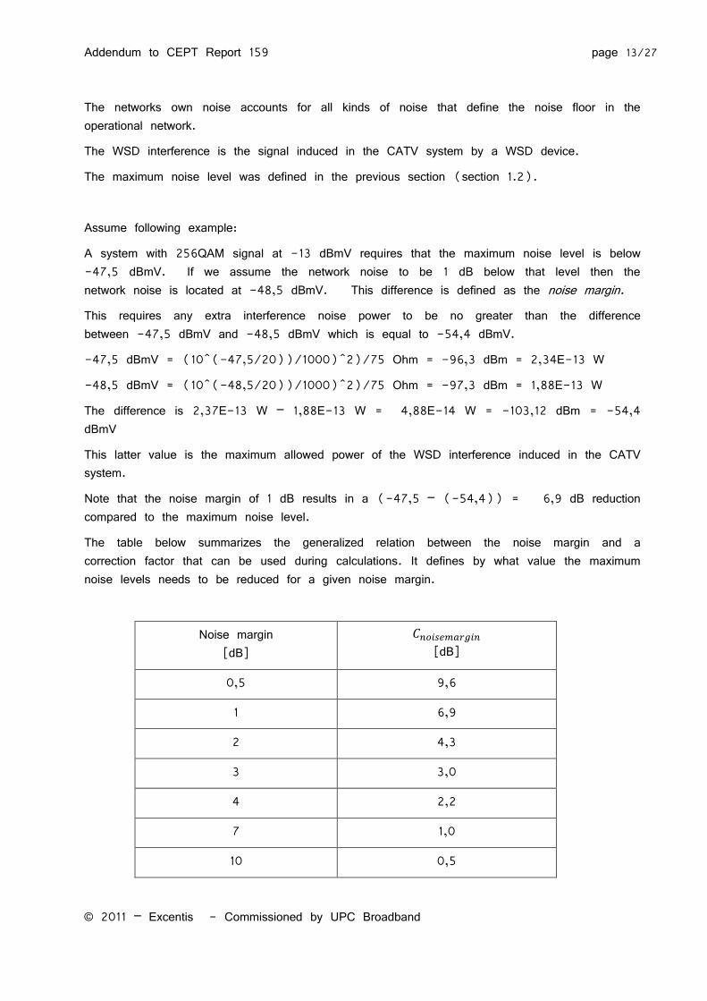
The table below summarizes the generalized relation between the noise margin and a correction factor that can be used during calculations. It defines by what value the maximum noise levels needs to be reduced for a given noise margin.
Noise margin [dB]
[dB]
0,5 9,6
1 6,9
2 4,3
3 3,0
4 2,2
7 1,0
10 0,5
Addendum to CEPT Report 159 page 14/27
© 2011 – Excentis - Commissioned by UPC Broadband
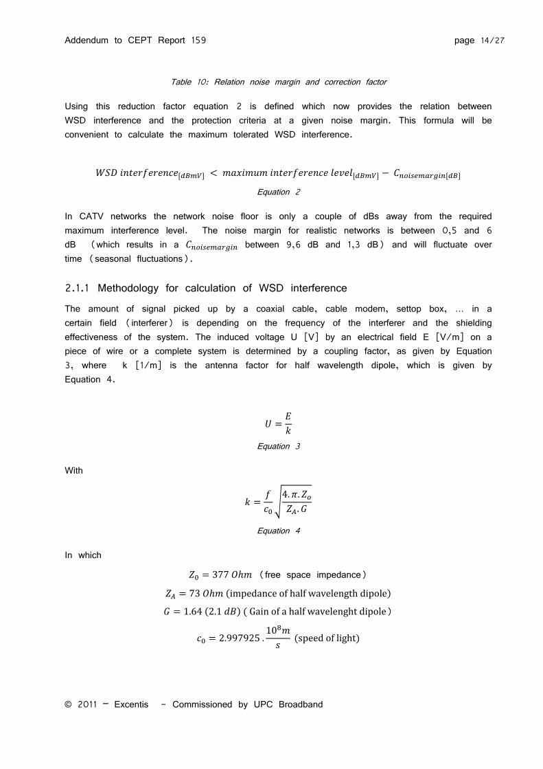
Table 10: Relation noise margin and correction factor
Using this reduction factor equation 2 is defined which now provides the relation between WSD interference and the protection criteria at a given noise margin. This formula will be convenient to calculate the maximum tolerated WSD interference.
Equation 2
In CATV networks the network noise floor is only a couple of dBs away from the required maximum interference level. The noise margin for realistic networks is between 0,5 and 6 dB (which results in a between 9,6 dB and 1,3 dB) and will fluctuate over time (seasonal fluctuations).
2.1.1 Methodology for calculation of WSD interference The amount of signal picked up by a coaxial cable, cable modem, settop box, … in a certain field (interferer) is depending on the frequency of the interferer and the shielding effectiveness of the system. The induced voltage U [V] by an electrical field E [V/m] on a piece of wire or a complete system is determined by a coupling factor, as given by Equation 3, where k [1/m] is the antenna factor for half wavelength dipole, which is given by Equation 4.
Equation 3
With
√
Equation 4
In which
(free space impedance)
( )
( ) ( )
( )
Addendum to CEPT Report 159 page 15/27
© 2011 – Excentis - Commissioned by UPC Broadband
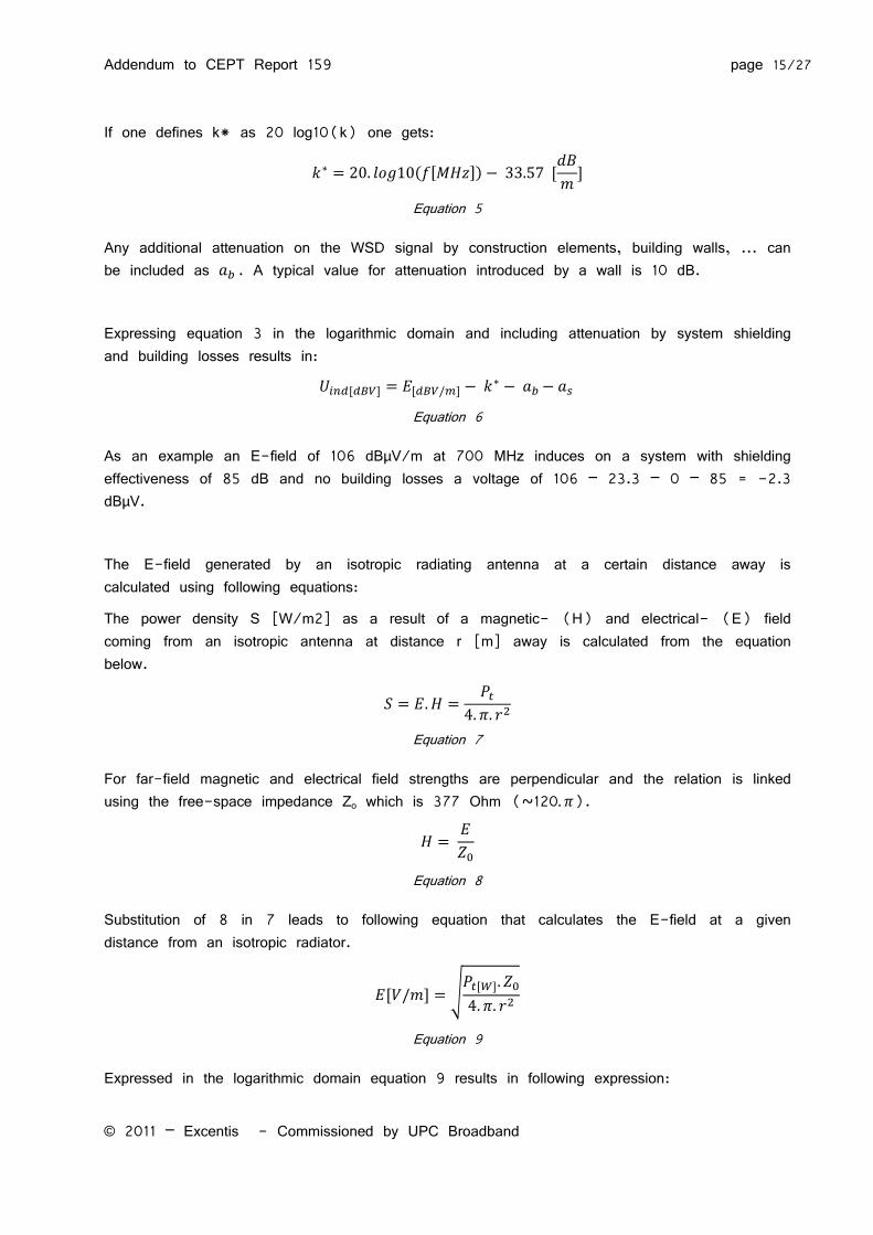
If one defines k* as 20 log10(k) one gets:
( )
Equation 5
Any additional attenuation on the WSD signal by construction elements, building walls, ... can be included as . A typical value for attenuation introduced by a wall is 10 dB.
Expressing equation 3 in the logarithmic domain and including attenuation by system shielding and building losses results in:
Equation 6
As an example an E-field of 106 dBµV/m at 700 MHz induces on a system with shielding effectiveness of 85 dB and no building losses a voltage of 106 – 23.3 – 0 – 85 = -2.3 dBµV.
The E-field generated by an isotropic radiating antenna at a certain distance away is calculated using following equations:
The power density S [W/m2] as a result of a magnetic- (H) and electrical- (E) field coming from an isotropic antenna at distance r [m] away is calculated from the equation below.
Equation 7
For far-field magnetic and electrical field strengths are perpendicular and the relation is linked using the free-space impedance Zo which is 377 Ohm (~120 ).
Equation 8
Substitution of 8 in 7 leads to following equation that calculates the E-field at a given distance from an isotropic radiator.
√
Equation 9
Expressed in the logarithmic domain equation 9 results in following expression:
Addendum to CEPT Report 159 page 16/27
© 2011 – Excentis - Commissioned by UPC Broadband
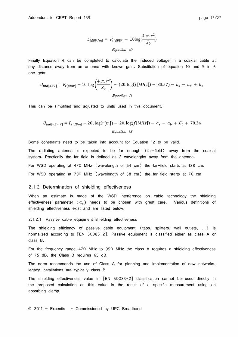
(
)
Equation 10
Finally Equation 4 can be completed to calculate the induced voltage in a coaxial cable at any distance away from an antenna with known gain. Substitution of equation 10 and 5 in 6 one gets:
(
) ( ( ) )
Equation 11
This can be simplified and adjusted to units used in this document:
( ) ( )
Equation 12
Some constraints need to be taken into account for Equation 12 to be valid.
The radiating antenna is expected to be far enough (far-field) away from the coaxial system. Practically the far field is defined as 2 wavelengths away from the antenna.
For WSD operating at 470 MHz (wavelength of 64 cm) the far-field starts at 128 cm.
For WSD operating at 790 MHz (wavelength of 38 cm) the far-field starts at 76 cm.
2.1.2 Determination of shielding effectiveness When an estimate is made of the WSD interference on cable technology the shielding effectiveness parameter ( ) needs to be chosen with great care. Various definitions of shielding effectiveness exist and are listed below.
2.1.2.1 Passive cable equipment shielding effectiveness
The shielding efficiency of passive cable equipment (taps, splitters, wall outlets, …) is normalized according to [EN 50083-2]. Passive equipment is classified either as class A or class B.
For the frequency range 470 MHz to 950 MHz the class A requires a shielding effectiveness of 75 dB, the Class B requires 65 dB.
The norm recommends the use of Class A for planning and implementation of new networks, legacy installations are typically class B.
The shielding effectiveness value in [EN 50083-2] classification cannot be used directly in the proposed calculation as this value is the result of a specific measurement using an absorbing clamp.
Addendum to CEPT Report 159 page 17/27
© 2011 – Excentis - Commissioned by UPC Broadband
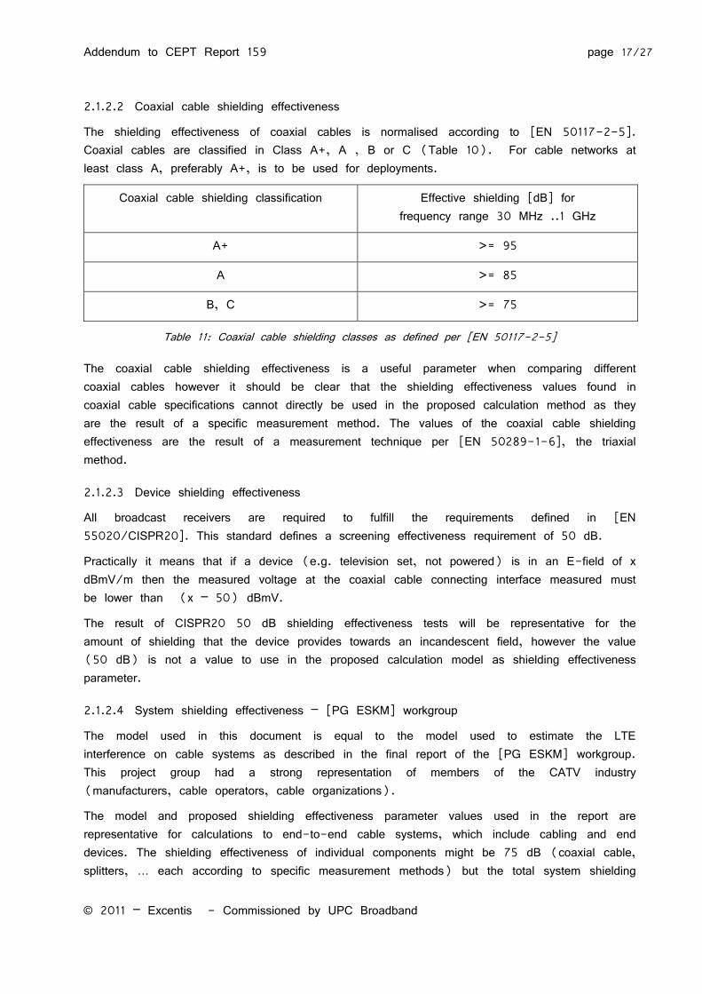
2.1.2.2 Coaxial cable shielding effectiveness
The shielding effectiveness of coaxial cables is normalised according to [EN 50117-2-5]. Coaxial cables are classified in Class A+, A , B or C (Table 10). For cable networks at least class A, preferably A+, is to be used for deployments.
Coaxial cable shielding classification Effective shielding [dB] for frequency range 30 MHz ..1 GHz
A+ >= 95
A >= 85
B, C >= 75
Table 11: Coaxial cable shielding classes as defined per [EN 50117-2-5]
The coaxial cable shielding effectiveness is a useful parameter when comparing different coaxial cables however it should be clear that the shielding effectiveness values found in coaxial cable specifications cannot directly be used in the proposed calculation method as they are the result of a specific measurement method. The values of the coaxial cable shielding effectiveness are the result of a measurement technique per [EN 50289-1-6], the triaxial method.
2.1.2.3 Device shielding effectiveness
All broadcast receivers are required to fulfill the requirements defined in [EN 55020/CISPR20]. This standard defines a screening effectiveness requirement of 50 dB.
Practically it means that if a device (e.g. television set, not powered) is in an E-field of x dBmV/m then the measured voltage at the coaxial cable connecting interface measured must be lower than (x – 50) dBmV.
The result of CISPR20 50 dB shielding effectiveness tests will be representative for the amount of shielding that the device provides towards an incandescent field, however the value (50 dB) is not a value to use in the proposed calculation model as shielding effectiveness parameter.
2.1.2.4 System shielding effectiveness – [PG ESKM] workgroup
The model used in this document is equal to the model used to estimate the LTE interference on cable systems as described in the final report of the [PG ESKM] workgroup. This project group had a strong representation of members of the CATV industry (manufacturers, cable operators, cable organizations).
The model and proposed shielding effectiveness parameter values used in the report are representative for calculations to end-to-end cable systems, which include cabling and end devices. The shielding effectiveness of individual components might be 75 dB (coaxial cable, splitters, … each according to specific measurement methods) but the total system shielding
Addendum to CEPT Report 159 page 18/27
© 2011 – Excentis - Commissioned by UPC Broadband
effectiveness will be a different value. (For sure the total shielding effectiveness can only be as high as the component with lowest shielding effectiveness).
The working group final report favors the values of 55 dB, 65 dB and 75 dB as system shielding effectiveness for a cable network connected end device (cable modem, settop box and TV). Additionally the remark is made that a value of 75 dB shielding effectiveness is considered very high and will only be attained by future devices.
The workgroup proposed values are best suited as shielding effectiveness parameter in the calculation model.
2.1.3 Resulting WSD interference on cable system Based upon the calculation methodology described and taking into account the protection criteria and noise margin correction explained, calculations can be done to find maximum EIRP of a WSD under various conditions.
During the calculation examples no building loss was included and was set to 0 dB. Furthermore no antenna gain was taken in account. The used was 6.9 dB which implies a noise margin of 1 dB.
2.1.3.1 Case I: Typical Rx level vs. Shielding effectiveness
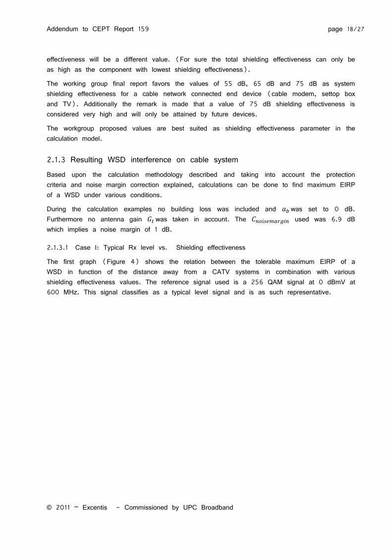
The first graph (Figure 4) shows the relation between the tolerable maximum EIRP of a WSD in function of the distance away from a CATV systems in combination with various shielding effectiveness values. The reference signal used is a 256 QAM signal at 0 dBmV at 600 MHz. This signal classifies as a typical level signal and is as such representative.
Addendum to CEPT Report 159 page 19/27
© 2011 – Excentis - Commissioned by UPC Broadband
Figure 4 : Typical QAM 256 operation combined with low, medium and high shielding factors
Example:
A 256QAM signal at 0 dBmV requires according to Table 4 a maximum noise level of -31.20 dBmV which is reduced with to -38.1 dBmV. A WSD at a distance of 2 m away from the cable system with shielding effectiveness of 75 dB will induce this power level if it is transmitting at an EIRP of 20 dBm (equation 12).
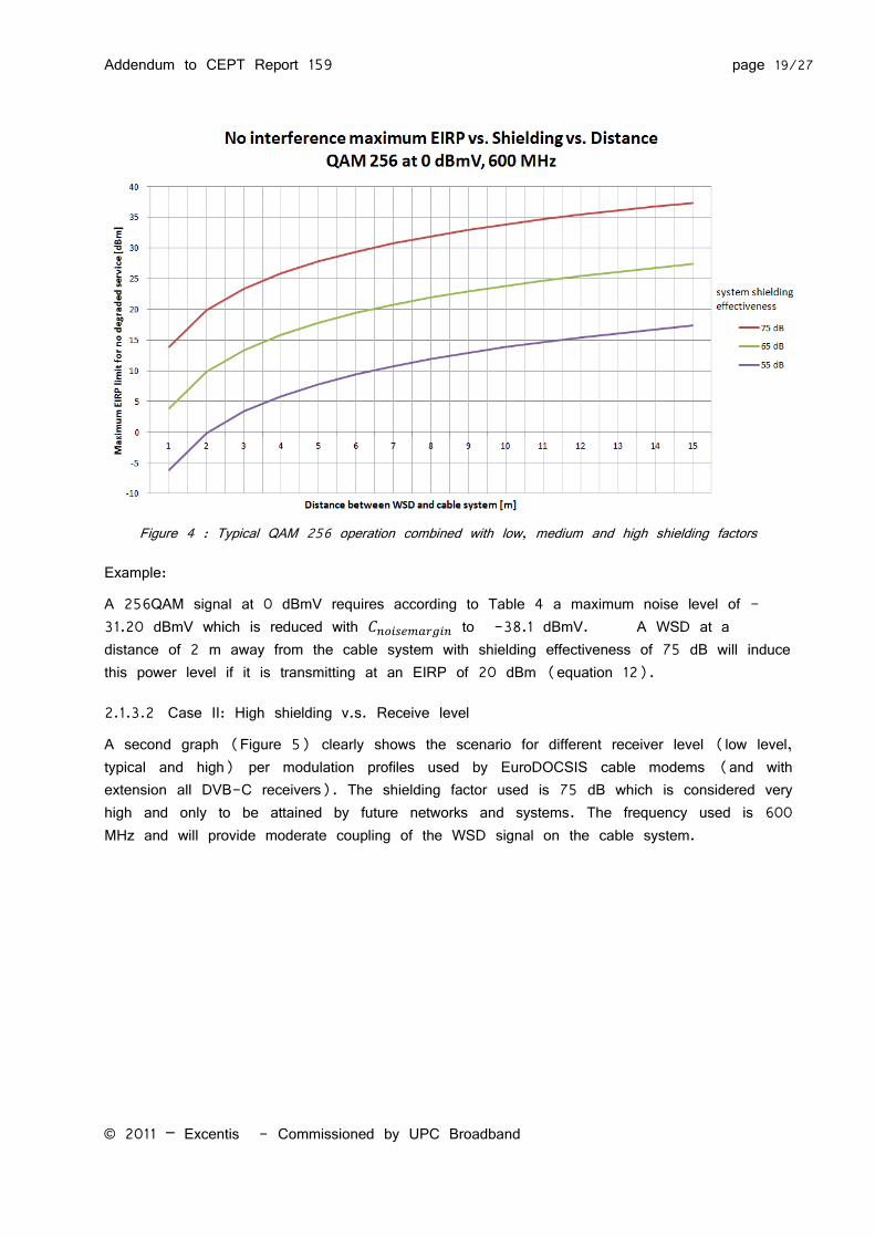
2.1.3.2 Case II: High shielding v.s. Receive level
A second graph (Figure 5) clearly shows the scenario for different receiver level (low level, typical and high) per modulation profiles used by EuroDOCSIS cable modems (and with extension all DVB-C receivers). The shielding factor used is 75 dB which is considered very high and only to be attained by future networks and systems. The frequency used is 600 MHz and will provide moderate coupling of the WSD signal on the cable system.
Addendum to CEPT Report 159 page 20/27
© 2011 – Excentis - Commissioned by UPC Broadband
Figure 5 : High shielding case
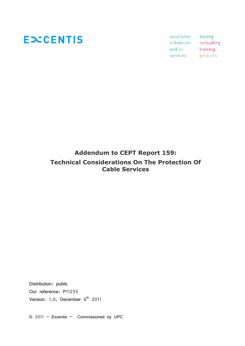
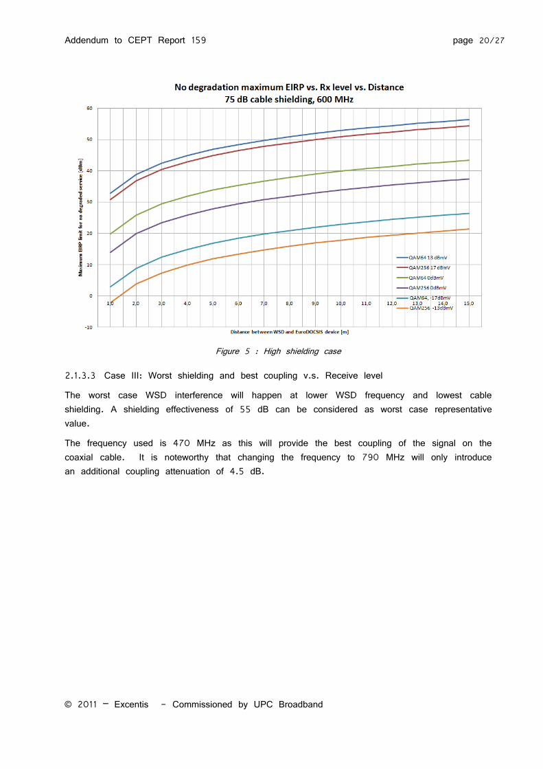
2.1.3.3 Case III: Worst shielding and best coupling v.s. Receive level
The worst case WSD interference will happen at lower WSD frequency and lowest cable shielding. A shielding effectiveness of 55 dB can be considered as worst case representative value.
The frequency used is 470 MHz as this will provide the best coupling of the signal on the coaxial cable. It is noteworthy that changing the frequency to 790 MHz will only introduce an additional coupling attenuation of 4.5 dB.
Addendum to CEPT Report 159 page 21/27
© 2011 – Excentis - Commissioned by UPC Broadband
Figure 6 : Low shielding case at various operational levels
2.1.4 Remarks on WSD bandwidth The calculations assume the WSD signal to be no larger than 8 MHz in bandwidth. If
the signals were wider then interference will be lower. E.g.: If the WSD signal was to be 16 MHz in bandwidth then EIRP power can be increased another 3 dB to reach the same interference level.
For WSD signals smaller than 8 MHz it was assumed that only a single WSD signal is disturbing the desired EuroDOCSIS/DVB-C signal. It should be clear that if WSD signals are proposed with 1 MHz in bandwidth and they are stacked in the 8 MHz band that the WSD maximum EIRP power level needs to be reduced by 9 dB as to cause the same disturbance as a single 8MHz wide WSD signal.
2.2 Experimental evidence of interference This section contains references to experiments that are representative as realistic situations with respect to the calculated results.
Addendum to CEPT Report 159 page 22/27
© 2011 – Excentis - Commissioned by UPC Broadband
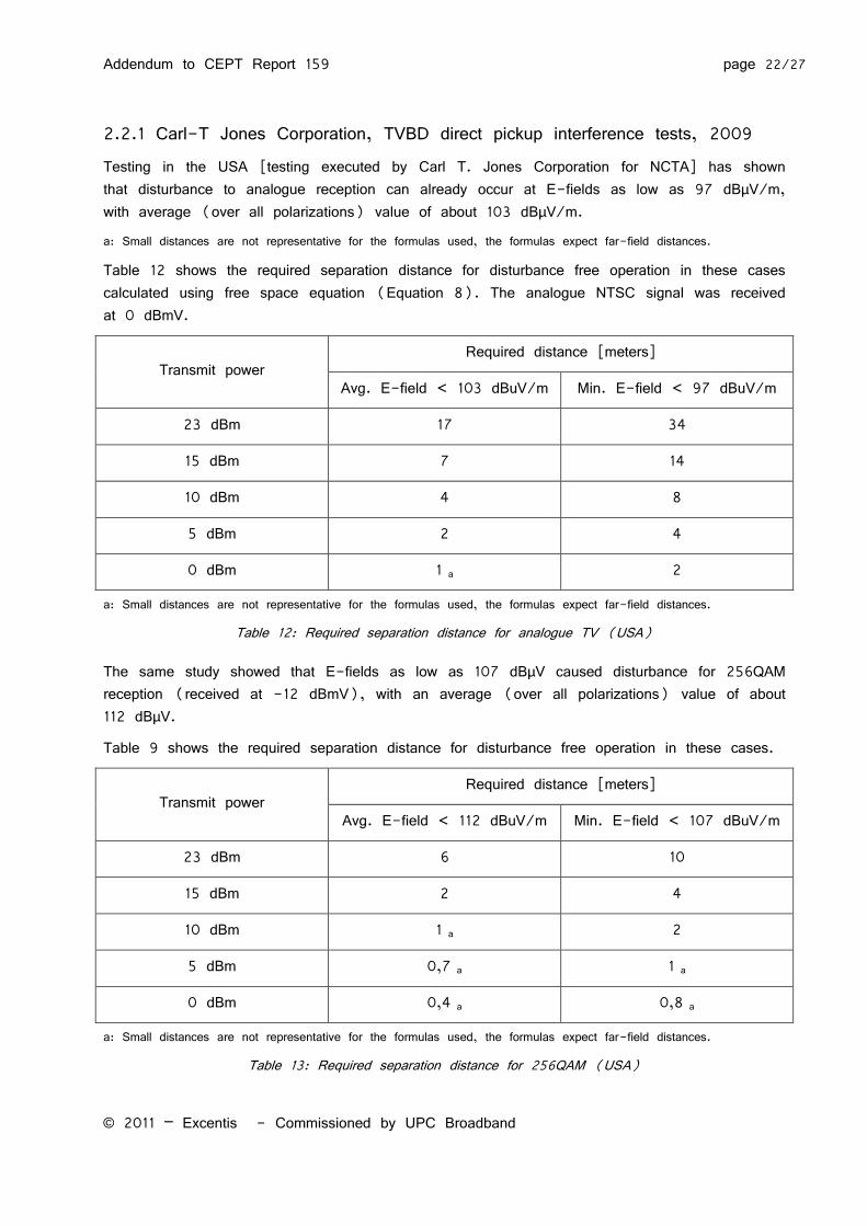
2.2.1 Carl-T Jones Corporation, TVBD direct pickup interference tests, 2009 Testing in the USA [testing executed by Carl T. Jones Corporation for NCTA] has shown that disturbance to analogue reception can already occur at E-fields as low as 97 dBµV/m, with average (over all polarizations) value of about 103 dBµV/m.
a: Small distances are not representative for the formulas used, the formulas expect far-field distances.
Table 12 shows the required separation distance for disturbance free operation in these cases calculated using free space equation (Equation 8). The analogue NTSC signal was received at 0 dBmV.
Transmit power Required distance [meters]
Avg. E-field < 103 dBuV/m Min. E-field < 97 dBuV/m
23 dBm 17 34
15 dBm 7 14
10 dBm 4 8
5 dBm 2 4
0 dBm 1 a 2
a: Small distances are not representative for the formulas used, the formulas expect far-field distances.
Table 12: Required separation distance for analogue TV (USA)
The same study showed that E-fields as low as 107 dBµV caused disturbance for 256QAM reception (received at -12 dBmV), with an average (over all polarizations) value of about 112 dBµV.
Table 9 shows the required separation distance for disturbance free operation in these cases.
Transmit power Required distance [meters]
Avg. E-field < 112 dBuV/m Min. E-field < 107 dBuV/m
23 dBm 6 10
15 dBm 2 4
10 dBm 1 a 2
5 dBm 0,7 a 1 a
0 dBm 0,4 a 0,8 a
a: Small distances are not representative for the formulas used, the formulas expect far-field distances.
Table 13: Required separation distance for 256QAM (USA)
Addendum to CEPT Report 159 page 23/27
© 2011 – Excentis - Commissioned by UPC Broadband
The values for a European case will be different since other modulation techniques, frequencies and reception levels are used. However as indicative values they are representative.
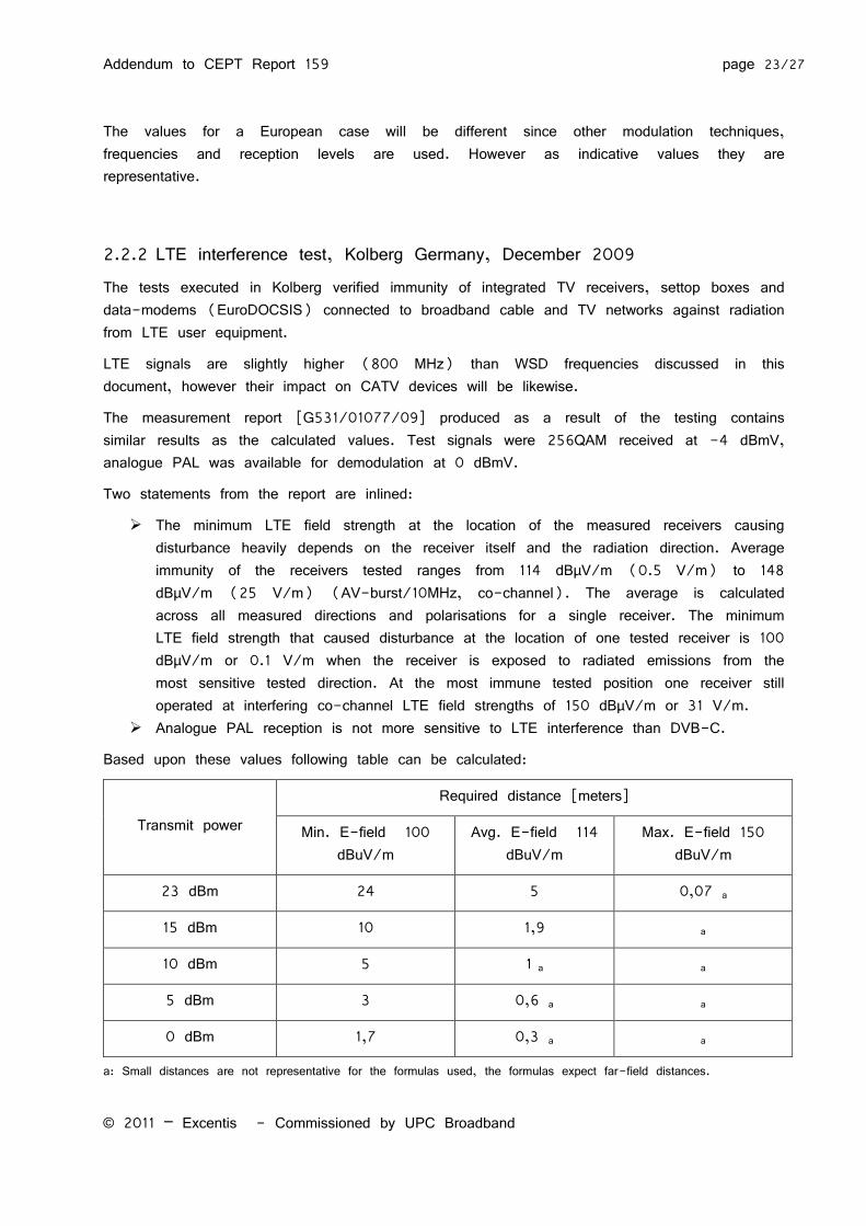
2.2.2 LTE interference test, Kolberg Germany, December 2009 The tests executed in Kolberg verified immunity of integrated TV receivers, settop boxes and data-modems (EuroDOCSIS) connected to broadband cable and TV networks against radiation from LTE user equipment.
LTE signals are slightly higher (800 MHz) than WSD frequencies discussed in this document, however their impact on CATV devices will be likewise.
The measurement report [G531/01077/09] produced as a result of the testing contains similar results as the calculated values. Test signals were 256QAM received at -4 dBmV, analogue PAL was available for demodulation at 0 dBmV.
Two statements from the report are inlined:
The minimum LTE field strength at the location of the measured receivers causing disturbance heavily depends on the receiver itself and the radiation direction. Average immunity of the receivers tested ranges from 114 dBµV/m (0.5 V/m) to 148 dBµV/m (25 V/m) (AV-burst/10MHz, co-channel). The average is calculated across all measured directions and polarisations for a single receiver. The minimum LTE field strength that caused disturbance at the location of one tested receiver is 100 dBµV/m or 0.1 V/m when the receiver is exposed to radiated emissions from the most sensitive tested direction. At the most immune tested position one receiver still operated at interfering co-channel LTE field strengths of 150 dBµV/m or 31 V/m.
Analogue PAL reception is not more sensitive to LTE interference than DVB-C.
Based upon these values following table can be calculated:
Transmit power
Required distance [meters]
Min. E-field 100 dBuV/m
Avg. E-field 114 dBuV/m
Max. E-field 150 dBuV/m
23 dBm 24 5 0,07 a
15 dBm 10 1,9 a
10 dBm 5 1 a a
5 dBm 3 0,6 a a
0 dBm 1,7 0,3 a a
a: Small distances are not representative for the formulas used, the formulas expect far-field distances.
Addendum to CEPT Report 159 page 24/27
© 2011 – Excentis - Commissioned by UPC Broadband
Table 14: Required separation distance based on Kolberg test results
Addendum to CEPT Report 159 page 25/27
© 2011 – Excentis - Commissioned by UPC Broadband
2.3 WSD EIRP limits From the provided calculation examples it should be clear that ad-hoc WSD operating as high as 20 to 23 dBm will cause severe and unacceptable interference (loss of service) in many households.
Reducing their maximum EIRP to 10 dBm would still prohibit users to adjust the WSD position as to minimise/eliminate interference since interference distance is still considerable.
Operating at 5 dBm would most likely result in an interference which allows a user to adjust the WSD position to minimise/eliminate the disturbance.
It should also be advised to use wide channels (>8MHz) for WSD as this will also reduce the interference on CATV coaxial cable deployed services. Should bandwidths smaller than 8 MHz be considered then an additional 3, 6 to 9 dB EIRP reduction is advised as to reduce the total power captured by 8MHz wide CATV receivers.
Addendum to CEPT Report 159 page 26/27
© 2011 – Excentis - Commissioned by UPC Broadband
References [1] EN 300 429: “Digital Video Broadcasting (DVB); Framing structure, channel coding and modulation
[2] ETSI TS 102 639-2: “Access and Terminals, Transmission and Multiplexing (ATTM); Third Generation Transmission Systems for Interactive Cable Television Services - IP Cable Modems;Part 2: Physical Layer”
ITU-T Recommendation J.222.1: "Third-generation transmission systems for interactive cable television services - IP cable modems: Physical layer specification". Annex B.6.3 CM BER Performance.
[3] EN 50083-2: “Cable networks for television signals, sound signals and interactive services = Part2: Electromagnetic compatibility for equipment”
[4] EN 50117-2-5: EN 50117-2-5:2004+A1(February 2008) “Coaxial cables — Part 2-1: Sectional specification for cables used in cabled distribution networks — Indoor drop cables for systems operating at 5 MHz — 3000 MHz”
[5] EN 60728-1: “Cable networks for television signals, sound signals and interactive services -Part 1: System performance of forward paths” Note: This European Standard supersedes EN 50083-7:1996 + A1:2000 + corrigendum August 2007.
[6] EN 50289-1-6:2002 “Communication cables - Specifications for test methods - Part 1-6: Electrical test methods - Electromagnetic performance”
[7] EN 55020: “Sound and television broadcast receivers and associated equipment — Immunity characteristics — Limits and methods of measurement”
[8] PG ESKM: Abschlussbericht - Projektgruppe “Untersuchung der EMV-Szenarien Kabel/Funk durch Mobilfunkanwendungen im Frequenzbereich 470 MHz bis 862 MHz” der AG EMV des ATRT
[9] Carl T. Jones Testing 2008/2009: “Carl-T Jones, TVBD direct pickup interference tests,2009”
[10] Measurement Report G531/01077/09: Immunity of integrated TV receivers, settop boxes and data-modems connected to broadband cable and TV networks against radiation from LTE user equipment.
Addendum to CEPT Report 159 page 27/27
© 2011 – Excentis - Commissioned by UPC Broadband
List of abbreviations C/I Carrier-to-Interference
C/N Carrier-to-Noise
CM Cable Modem
CMTS Cable Modem Termination System
DPU Direct pick-up
DS Downstream (Forward Path)
DVB-C Digital Video Broadcasting-Cable
EIRP Equivalent Isotropically Radiated Power
HE Headend
LTE Long Term Evolution
ON Optical Node
PAL Phase Alternate Line
PSI/SI Program Specific Information/Service Information
S/N Signal-to-Noise
TDM Time Division Multiplexing
TVBD Television Band Device
US Upstream (Return path)
WSD White Space Device