ADDENDUM NO. 1 - Calaveras County Water District - … 22 BidNotiice/Addendum No.1...Replacement...
27
Copper Cove Lift Station #22 1 August 27, 2014 Replacement Project Addendum No.1 CALAVERAS COUNTY WATER DISTRICT COPPER COVE SEWER LIFT STATION #22 REPLACEMENT PROJECT ADDENDUM NO. 1 Date Issued: August 27, 2014 **** Receipt of addenda to be acknowledged by Bidders on the Proposal, Section 00300, Page 2. Failure to acknowledge receipt may cause rejection of bid. **** The Contract Documents are added to, revised, and modified as stated herein and these revisions supersede all conflicting requirements that may be found elsewhere in the original plans and specifications. SECTION REVISIONS TO SPECIFICATIONS Section 00010, Notice Inviting Bids Make the following revisions: *** The Bid Opening date has changed; the new Bid Opening time and date is 2:00 PM on Tuesday, September 23 rd , 2014. *** Completion of work is three hundred twenty (320) calendar days from the date of the Notice to Proceed. Submit information requests (RFI’s) by 1:00 PM on September 17 th , 2014. Section 00350, Measurement and Payment For Bid Item No.7, clarification as follows: Contractor is to furnish and install 90”x106” precast transformer pad and cast in place pad for switchboard, all conduits and switchboard. District pays for PG&E’s scope of work, i.e. furnish and install transformer, primary and secondary conductors from pole to transformer to switchboard. Section 00400, Information Required of Bidder For Section 00400, Information Required of Bidders, delete and replace with attached updated version with the following changes: a. Identify Electrical Subcontractor and provide references for three (3) projects similar to this project completed within the last (5) years. b. Identify company performing Electrical Systems Analysis in accordance with Section 16605, and provide references for three (3) projects similar to this project completed within the last (5) years. c. Identify control systems integrator in Section 16010, Article 1.01 H performing work; or to prequalify integrator shall be C-10 electrical contractor, certified by Control Systems Integrator Association (CSIA) and UL508A shop.
Transcript of ADDENDUM NO. 1 - Calaveras County Water District - … 22 BidNotiice/Addendum No.1...Replacement...

Copper Cove Lift Station #22 1 August 27, 2014 Replacement Project Addendum No.1
CALAVERAS COUNTY WATER DISTRICT COPPER COVE SEWER LIFT STATION #22
REPLACEMENT PROJECT
ADDENDUM NO. 1
Date Issued: August 27, 2014
**** Receipt of addenda to be acknowledged by Bidders on the Proposal, Section 00300, Page 2. Failure to acknowledge receipt may cause rejection of bid. **** The Contract Documents are added to, revised, and modified as stated herein and these revisions supersede all conflicting requirements that may be found elsewhere in the original plans and specifications.
SECTION REVISIONS TO SPECIFICATIONS
Section 00010, Notice Inviting Bids
Make the following revisions:
*** The Bid Opening date has changed; the new Bid Opening time and date is 2:00 PM on Tuesday, September 23rd, 2014. ***
Completion of work is three hundred twenty (320) calendar days from the date of the Notice to Proceed.
Submit information requests (RFI’s) by 1:00 PM on September 17th, 2014.
Section 00350, Measurement and Payment
For Bid Item No.7, clarification as follows:
Contractor is to furnish and install 90”x106” precast transformer pad and cast in place pad for switchboard, all conduits and switchboard. District pays for PG&E’s scope of work, i.e. furnish and install transformer, primary and secondary conductors from pole to transformer to switchboard.
Section 00400, Information Required of Bidder
For Section 00400, Information Required of Bidders, delete and replace with attached updated version with the following changes:
a. Identify Electrical Subcontractor and provide references for three (3) projects similar to this project completed within the last (5) years.
b. Identify company performing Electrical Systems Analysis in accordance with Section 16605, and provide references for three (3) projects similar to this project completed within the last (5) years.
c. Identify control systems integrator in Section 16010, Article 1.01 H performing work; or to prequalify integrator shall be C-10 electrical contractor, certified by Control Systems Integrator Association (CSIA) and UL508A shop.
Copper Cove Lift Station #22 2 August 27, 2014 Replacement Project Addendum No.1
SECTION REVISIONS TO SPECIFICATIONS
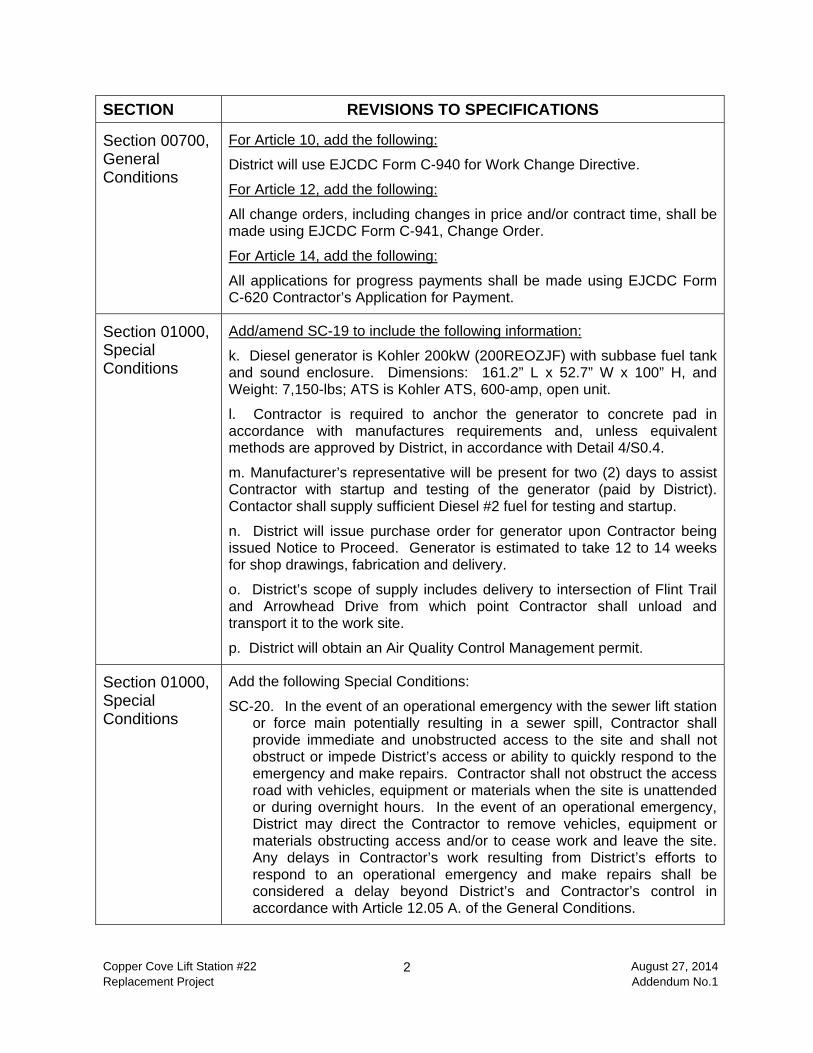
Section 00700, General Conditions
For Article 10, add the following:
District will use EJCDC Form C-940 for Work Change Directive.
For Article 12, add the following:
All change orders, including changes in price and/or contract time, shall be made using EJCDC Form C-941, Change Order.
For Article 14, add the following:
All applications for progress payments shall be made using EJCDC Form C-620 Contractor’s Application for Payment.
Section 01000, Special Conditions
Add/amend SC-19 to include the following information:
k. Diesel generator is Kohler 200kW (200REOZJF) with subbase fuel tank and sound enclosure. Dimensions: 161.2” L x 52.7” W x 100” H, and Weight: 7,150-lbs; ATS is Kohler ATS, 600-amp, open unit.
l. Contractor is required to anchor the generator to concrete pad in accordance with manufactures requirements and, unless equivalent methods are approved by District, in accordance with Detail 4/S0.4.
m. Manufacturer’s representative will be present for two (2) days to assist Contractor with startup and testing of the generator (paid by District). Contactor shall supply sufficient Diesel #2 fuel for testing and startup.
n. District will issue purchase order for generator upon Contractor being issued Notice to Proceed. Generator is estimated to take 12 to 14 weeks for shop drawings, fabrication and delivery.
o. District’s scope of supply includes delivery to intersection of Flint Trail and Arrowhead Drive from which point Contractor shall unload and transport it to the work site.
p. District will obtain an Air Quality Control Management permit.
Section 01000, Special Conditions
Add the following Special Conditions:
SC-20. In the event of an operational emergency with the sewer lift station or force main potentially resulting in a sewer spill, Contractor shall provide immediate and unobstructed access to the site and shall not obstruct or impede District’s access or ability to quickly respond to the emergency and make repairs. Contractor shall not obstruct the access road with vehicles, equipment or materials when the site is unattended or during overnight hours. In the event of an operational emergency, District may direct the Contractor to remove vehicles, equipment or materials obstructing access and/or to cease work and leave the site. Any delays in Contractor’s work resulting from District’s efforts to respond to an operational emergency and make repairs shall be considered a delay beyond District’s and Contractor’s control in accordance with Article 12.05 A. of the General Conditions.

Copper Cove Lift Station #22 3 August 27, 2014 Replacement Project Addendum No.1
SECTION REVISIONS TO SPECIFICATIONS
Section 01000, Special Conditions
Add the following special conditions:
SC-21. A test pit was made at the new wet well location; soil consisted of weathered rock that could be excavated to a depth of refusal of approximately ten (10) feet below existing grade. At greater depths, the rock is less weathered, highly resistant and the excavation could not be advanced any deeper using standard heavy equipment. It is assumed that blasting will be required to remove the rock and complete excavations greater than ten (10) feet below existing grade.
SC-22. Contractor is responsible for removing all trees, branches, stumps and roots within 10-feet of build foundation, transformer pad, generator and electrical panel, antenna, trenches and excavations or otherwise directly within the zone of work. If tree branches are removed or damaged at any location by Contractor’s activities, they shall be neatly cut. All waste material shall be removed from the work site and properly disposed of at an approved facility.
SC-23. Access to the work site is via a narrow, gravel road with overhead tree branches, sharp radius turns, and uneven grade/terrain. District has obtained tentative permission for a staging area near the cattle gate at the top of Flint Trail and limited staging areas along/adjacent to the gravel road; staging areas will be discussed at the pre-construction meeting. Contractor shall request permission before clearing and grubbing proposed staging areas. Clearing and grubbing shall not damage any rock outcroppings. In addition to delivery/arrival of materials and equipment by suppliers to nearest street to the job site, i.e. intersection of Flint Trail and Arrowhead Drive, the Contractor is responsible for all additional transport/hauling of materials and equipment along the gravel access road to the lift station work site. Cattle are present on the work site and the cattle gate shall be kept close at all times when not being used for immediate ingress/egress.
Section 06630, Fiberglass Wet Well
For Article 2.03, Design Criteria, add the following:
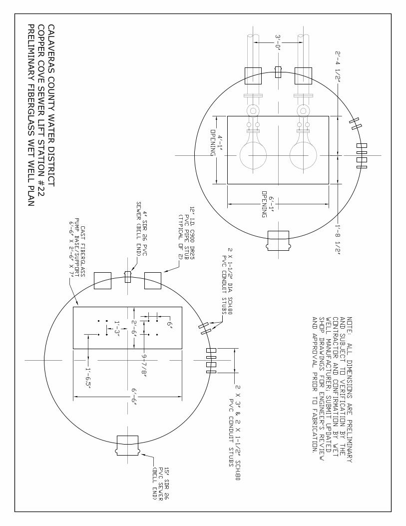
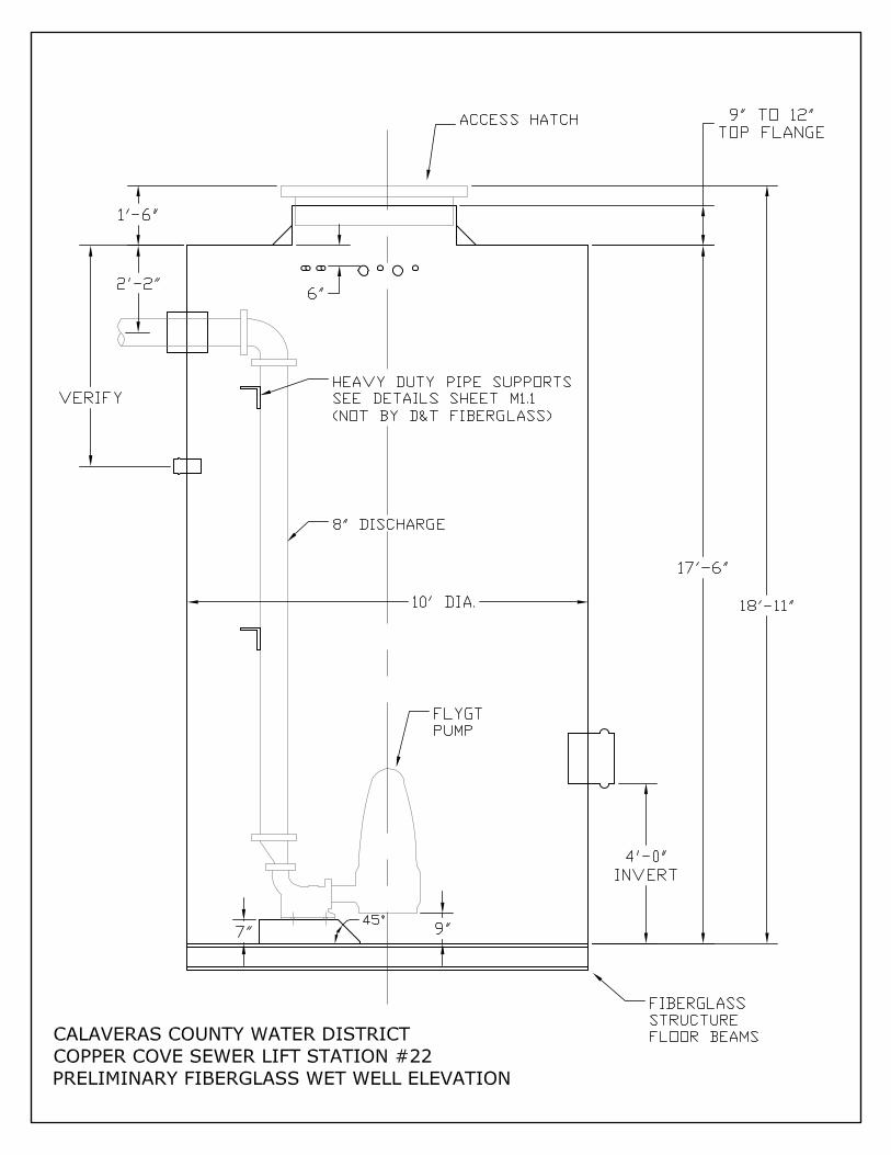
E. Wet well dimensions, pipe and conduit penetrations, supports and other features are shown on the attached elevation and plan drawings; all dimensions are preliminary. The Contractor shall obtain shop drawings prepared by the wet well manufacturer, and Contractor is required to check all dimensions and note discrepancies before submitting shop drawings to Project Engineer for review and approval for fabrication.
Section 16010, Page 16010-5
Revise Article 1.04 A., as follows:
A. Submit five (5) sets of electrical submittals for approval in accordance with this subsection and Section 00700, General Conditions and Section 00800, Supplementary Conditions.
Copper Cove Lift Station #22 4 August 27, 2014 Replacement Project Addendum No.1
SHEET NO. REVISIONS TO DRAWINGS
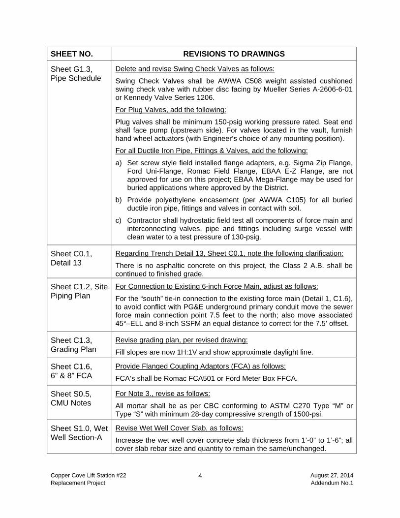
Sheet G1.3, Pipe Schedule
Delete and revise Swing Check Valves as follows:
Swing Check Valves shall be AWWA C508 weight assisted cushioned swing check valve with rubber disc facing by Mueller Series A-2606-6-01 or Kennedy Valve Series 1206.
For Plug Valves, add the following:
Plug valves shall be minimum 150-psig working pressure rated. Seat end shall face pump (upstream side). For valves located in the vault, furnish hand wheel actuators (with Engineer’s choice of any mounting position).
For all Ductile Iron Pipe, Fittings & Valves, add the following:
a) Set screw style field installed flange adapters, e.g. Sigma Zip Flange, Ford Uni-Flange, Romac Field Flange, EBAA E-Z Flange, are not approved for use on this project; EBAA Mega-Flange may be used for buried applications where approved by the District.
b) Provide polyethylene encasement (per AWWA C105) for all buried ductile iron pipe, fittings and valves in contact with soil.
c) Contractor shall hydrostatic field test all components of force main and interconnecting valves, pipe and fittings including surge vessel with clean water to a test pressure of 130-psig.
Sheet C0.1, Detail 13
Regarding Trench Detail 13, Sheet C0.1, note the following clarification:
There is no asphaltic concrete on this project, the Class 2 A.B. shall be continued to finished grade.
Sheet C1.2, Site Piping Plan
For Connection to Existing 6-inch Force Main, adjust as follows:
For the “south” tie-in connection to the existing force main (Detail 1, C1.6), to avoid conflict with PG&E underground primary conduit move the sewer force main connection point 7.5 feet to the north; also move associated 45°–ELL and 8-inch SSFM an equal distance to correct for the 7.5’ offset.
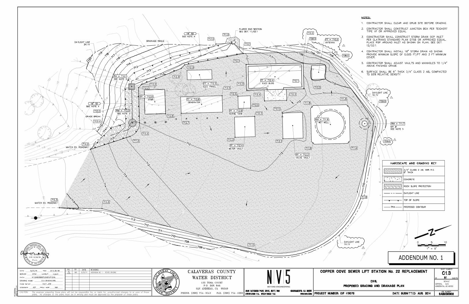
Sheet C1.3, Grading Plan
Revise grading plan, per revised drawing:
Fill slopes are now 1H:1V and show approximate daylight line.
Sheet C1.6, 6” & 8” FCA
Provide Flanged Coupling Adaptors (FCA) as follows:
FCA’s shall be Romac FCA501 or Ford Meter Box FFCA.
Sheet S0.5, CMU Notes
For Note 3., revise as follows:
All mortar shall be as per CBC conforming to ASTM C270 Type “M” or Type “S” with minimum 28-day compressive strength of 1500-psi.
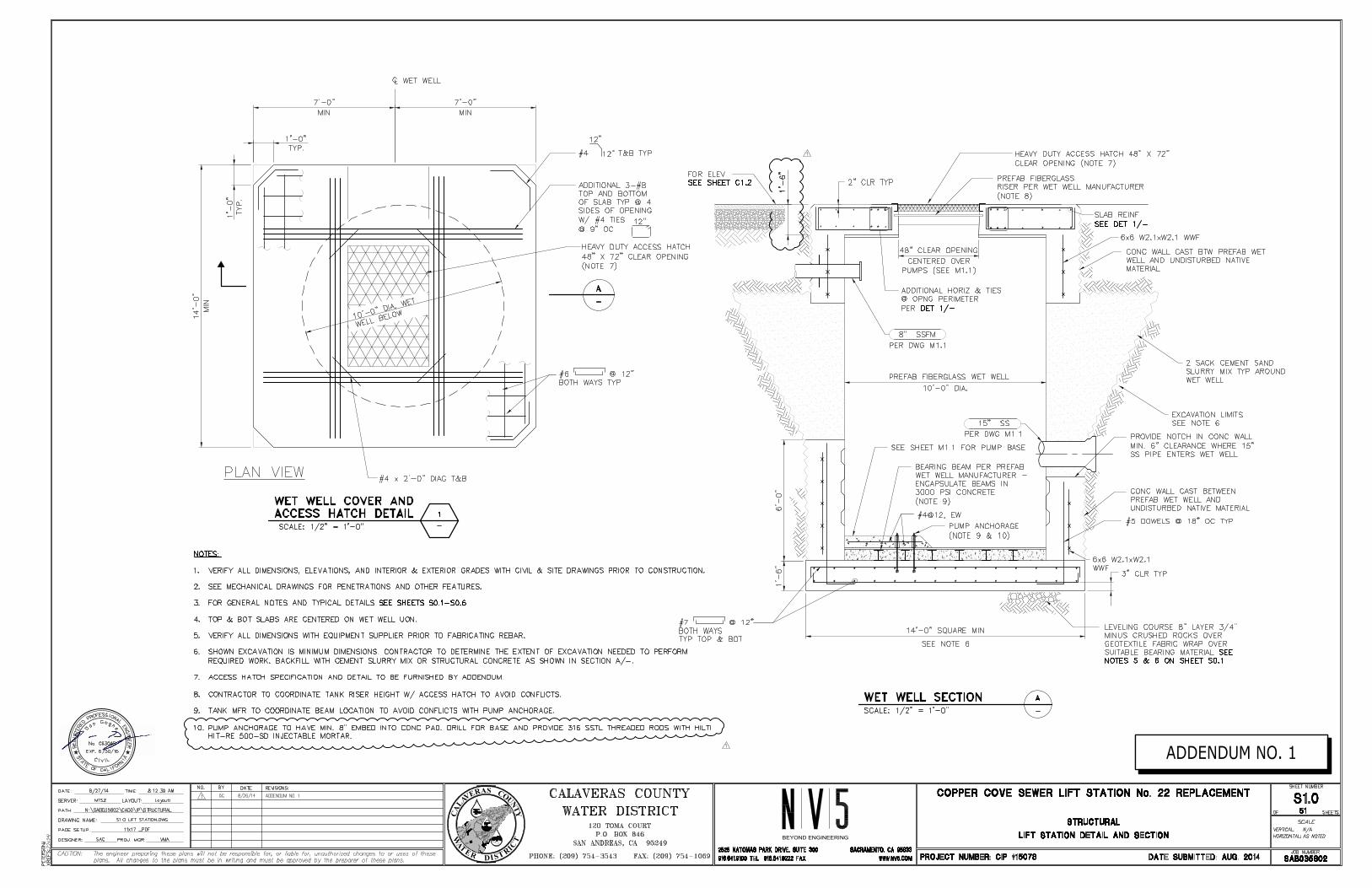
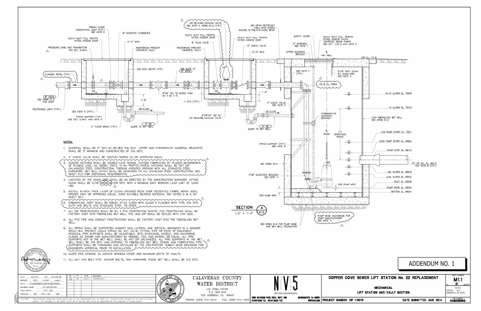
Sheet S1.0, Wet Well Section-A
Revise Wet Well Cover Slab, as follows:
Increase the wet well cover concrete slab thickness from 1’-0” to 1’-6”; all cover slab rebar size and quantity to remain the same/unchanged.
Copper Cove Lift Station #22 5 August 27, 2014 Replacement Project Addendum No.1
SHEET NO. REVISIONS TO DRAWINGS
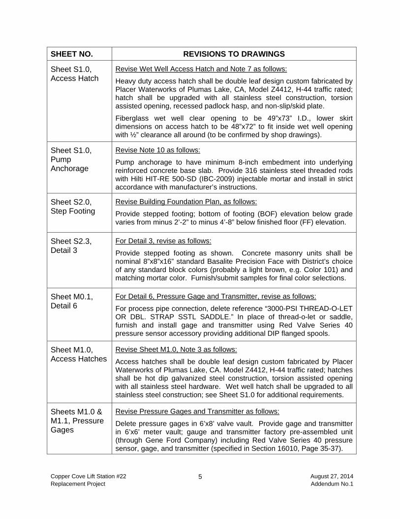
Sheet S1.0, Access Hatch
Revise Wet Well Access Hatch and Note 7 as follows:
Heavy duty access hatch shall be double leaf design custom fabricated by Placer Waterworks of Plumas Lake, CA, Model Z4412, H-44 traffic rated; hatch shall be upgraded with all stainless steel construction, torsion assisted opening, recessed padlock hasp, and non-slip/skid plate.
Fiberglass wet well clear opening to be 49”x73” I.D., lower skirt dimensions on access hatch to be 48”x72” to fit inside wet well opening with ½” clearance all around (to be confirmed by shop drawings).
Sheet S1.0, Pump Anchorage
Revise Note 10 as follows:
Pump anchorage to have minimum 8-inch embedment into underlying reinforced concrete base slab. Provide 316 stainless steel threaded rods with Hilti HIT-RE 500-SD (IBC-2009) injectable mortar and install in strict accordance with manufacturer’s instructions.
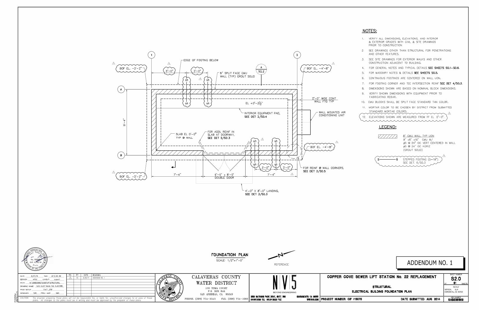
Sheet S2.0, Step Footing
Revise Building Foundation Plan, as follows:
Provide stepped footing; bottom of footing (BOF) elevation below grade varies from minus 2’-2” to minus 4’-8” below finished floor (FF) elevation.
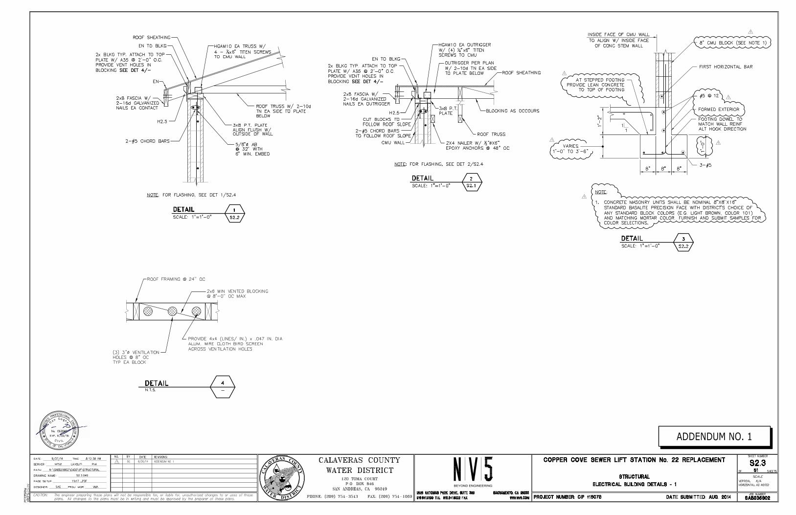
Sheet S2.3, Detail 3
For Detail 3, revise as follows:
Provide stepped footing as shown. Concrete masonry units shall be nominal 8”x8”x16” standard Basalite Precision Face with District’s choice of any standard block colors (probably a light brown, e.g. Color 101) and matching mortar color. Furnish/submit samples for final color selections.
Sheet M0.1, Detail 6
For Detail 6, Pressure Gage and Transmitter, revise as follows:
For process pipe connection, delete reference “3000-PSI THREAD-O-LET OR DBL. STRAP SSTL SADDLE.” In place of thread-o-let or saddle, furnish and install gage and transmitter using Red Valve Series 40 pressure sensor accessory providing additional DIP flanged spools.
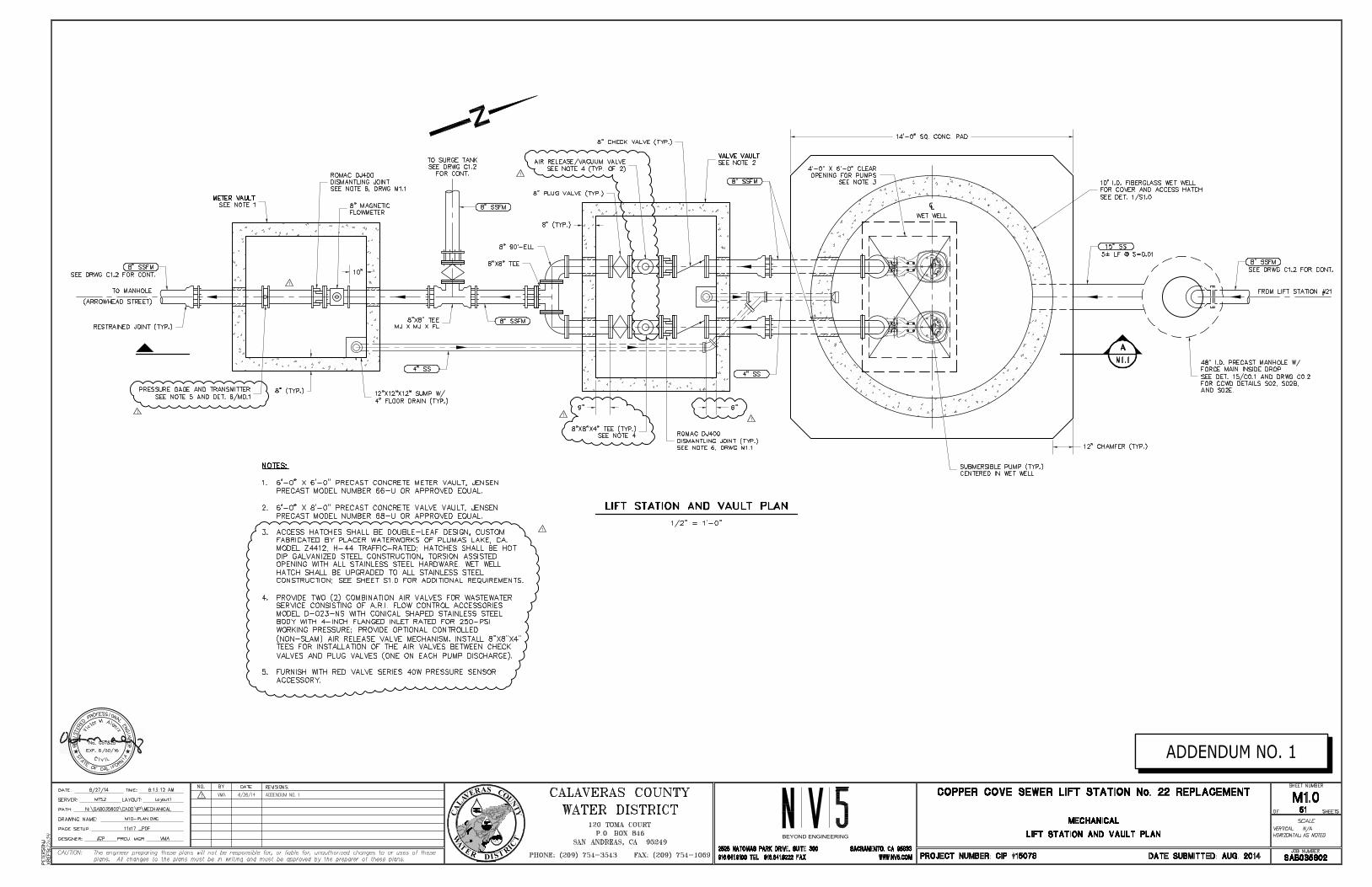
Sheet M1.0, Access Hatches
Revise Sheet M1.0, Note 3 as follows:
Access hatches shall be double leaf design custom fabricated by Placer Waterworks of Plumas Lake, CA. Model Z4412, H-44 traffic rated; hatches shall be hot dip galvanized steel construction, torsion assisted opening with all stainless steel hardware. Wet well hatch shall be upgraded to all stainless steel construction; see Sheet S1.0 for additional requirements.
Sheets M1.0 & M1.1, Pressure Gages
Revise Pressure Gages and Transmitter as follows:
Delete pressure gages in 6’x8’ valve vault. Provide gage and transmitter in 6’x6’ meter vault; gauge and transmitter factory pre-assembled unit (through Gene Ford Company) including Red Valve Series 40 pressure sensor, gage, and transmitter (specified in Section 16010, Page 35-37).
Copper Cove Lift Station #22 6 August 27, 2014 Replacement Project Addendum No.1
SHEET NO. REVISIONS TO DRAWINGS
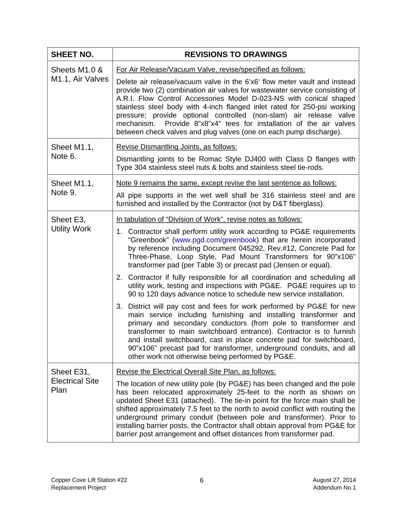
Sheets M1.0 & M1.1, Air Valves
For Air Release/Vacuum Valve, revise/specified as follows:
Delete air release/vacuum valve in the 6’x6’ flow meter vault and instead provide two (2) combination air valves for wastewater service consisting of A.R.I. Flow Control Accessories Model D-023-NS with conical shaped stainless steel body with 4-inch flanged inlet rated for 250-psi working pressure; provide optional controlled (non-slam) air release valve mechanism. Provide 8”x8”x4” tees for installation of the air valves between check valves and plug valves (one on each pump discharge).
Sheet M1.1, Note 6.
Revise Dismantling Joints, as follows:
Dismantling joints to be Romac Style DJ400 with Class D flanges with Type 304 stainless steel nuts & bolts and stainless steel tie-rods.
Sheet M1.1, Note 9.
Note 9 remains the same, except revise the last sentence as follows:
All pipe supports in the wet well shall be 316 stainless steel and are furnished and installed by the Contractor (not by D&T fiberglass).
Sheet E3, Utility Work
In tabulation of “Division of Work”, revise notes as follows:
1. Contractor shall perform utility work according to PG&E requirements “Greenbook” (www.pgd.com/greenbook) that are herein incorporated by reference including Document 045292, Rev.#12, Concrete Pad for Three-Phase, Loop Style, Pad Mount Transformers for 90”x106” transformer pad (per Table 3) or precast pad (Jensen or equal).
2. Contractor if fully responsible for all coordination and scheduling all utility work, testing and inspections with PG&E. PG&E requires up to 90 to 120 days advance notice to schedule new service installation.
3. District will pay cost and fees for work performed by PG&E for new main service including furnishing and installing transformer and primary and secondary conductors (from pole to transformer and transformer to main switchboard entrance). Contractor is to furnish and install switchboard, cast in place concrete pad for switchboard, 90”x106” precast pad for transformer, underground conduits, and all other work not otherwise being performed by PG&E.
Sheet E31, Electrical Site Plan
Revise the Electrical Overall Site Plan, as follows:
The location of new utility pole (by PG&E) has been changed and the pole has been relocated approximately 25-feet to the north as shown on updated Sheet E31 (attached). The tie-in point for the force main shall be shifted approximately 7.5 feet to the north to avoid conflict with routing the underground primary conduit (between pole and transformer). Prior to installing barrier posts, the Contractor shall obtain approval from PG&E for barrier post arrangement and offset distances from transformer pad.
Copper Cove LS 22 / CIP 15078 00400-1 INFORMATION REQUIRED OF BIDDER ADDENDUM NO.1 August 27, 2014
Section 00400
INFORMATION REQUIRED OF BIDDER GENERAL INFORMATION
All bidders are required to furnish the following information; failure to enclose this information with the bid will render the Proposal informal and may cause its rejection.
A. CONTRACTOR INFORMATION Contractor's name and address: ____________________________________________________________________
____________________________________________________________________
____________________________________________________________________
Contractor's telephone: ____________________
Fax Number: _____________________________
Email: _____________________________
Contractor’s State License No._____________________________________________
Supplemental Classifications held, if any: ____________________________________
Number of years as a contractor in construction work of this type: ________________
Names and titles of all officers of contractor's firm:
____________________________________________________________________
____________________________________________________________________
____________________________________________________________________
____________________________________________________________________
Name of person who inspected site of proposed work for your firm:
Name: _______________________________________________________________
Date of Inspection: _____________________________________________________
Copper Cove LS 22 / CIP 15078 00400-2 INFORMATION REQUIRED OF BIDDER ADDENDUM NO.1 August 27, 2014
BOND: Agent, company name, address, telephone and fax number of surety company who will provide the required bonds on this contract: Agent: _____________________________________________________________ Company Name: _____________________________________________________ Address: ____________________________________________________________
____________________________________________________________________
Phone: (_____) _____________________ Fax: (_____) _____________________ INSURANCE: Agent, company name, address, telephone, and fax number of insurance company who will provide the required insurance on this contract: Agent: ______________________________________________________________ Company Name: ______________________________________________________ Address: ____________________________________________________________
____________________________________________________________________
Phone: (_____) _____________________Fax: (_____) _____________________ REFERENCES: List three (3) similar projects completed within last five (5) years ** Project Name $ Amount Contact Person Phone
1.
2.
3.
** Upon request by the District, bidders shall submit additional reference information and details for the projects listed above.
Copper Cove LS 22 / CIP 15078 00400-3 INFORMATION REQUIRED OF BIDDER ADDENDUM NO.1 August 27, 2014
B. ELECTRICAL SUBCONTRACTOR Contact Information (name, address and phone):
____________________________________________________________________
____________________________________________________________________
____________________________________________________________________
References: List three (3) similar projects within last five (5) years: Project Name $ Amount Contact Person Phone
1.
2.
3.
C. ELECTRICAL SYSTEM ANALYSIS Provide the following information for company performing electrical systems analysis in accordance with Section 16605 of the specifications.
Contact Information (name, address and phone):
____________________________________________________________________
____________________________________________________________________
____________________________________________________________________
References: List three (3) similar projects within last five (5) years: Project Name $ Amount Contact Person Phone
1.
2.
3.
Copper Cove LS 22 / CIP 15078 00400-4 INFORMATION REQUIRED OF BIDDER ADDENDUM NO.1 August 27, 2014
D. CONTROL SYSTEMS INTEGRATOR Contact Information (name, address and phone):
____________________________________________________________________
____________________________________________________________________
____________________________________________________________________
Is the Integrator listed in Section 16010, Article 1.01 H or prequalified? _______________ Does Integrator have a California C‐10, Electrical Contractor’s License? ________________ Is Integrator certified by Underwriters Laboratories (UL) per UL508A? ________________ Is Integrator certified by Control Systems Integrator Association (CSIA): ________________
Copper Cove LS 22 / CIP 15078 00400-5 INFORMATION REQUIRED OF BIDDER ADDENDUM NO.1 August 27, 2014
INFORMATION REQUIRED OF BIDDER
LIST OF SUBCONTRACTORS
The bidder shall list each subcontractor who will perform work under this contract in excess of one‐half percent of the total bid price. After the opening of proposals, no changes or substitutions will be allowed without the written approval of CCWD. Work to be Performed Subcontractor's Name, Address, Phone & License 1. _________________________ ________________________________________ _________________________ ________________________________________ _________________________ ________________________________________ _________________________ ________________________________________ 2. _________________________ ________________________________________ _________________________ ________________________________________ _________________________ ________________________________________ _________________________ ________________________________________ 3. _________________________ ________________________________________ _________________________ ________________________________________ _________________________ ________________________________________ _________________________ ________________________________________ 4. _________________________ ________________________________________ _________________________ ________________________________________ _________________________ ________________________________________ _________________________ ________________________________________ 5. _________________________ ________________________________________ _________________________ ________________________________________ _________________________ ________________________________________ _________________________ ________________________________________ 6. _________________________ ________________________________________ _________________________ ________________________________________ _________________________ ________________________________________ _________________________ ________________________________________
(Attach additional sheets if needed)
EJCDC® C‐940, Work Change Directive. Prepared and published 2013 by the Engineers Joint Contract Documents Committee.
Page 1 of 1
Work Change Directive No.
Date of Issuance: Effective Date:
Owner: Owner’s Contract No.:
Contractor: Contractor’s Project No.:
Engineer: Engineer's Project No.:
Project: Contract Name:
Contractor is directed to proceed promptly with the following change(s):
Description:
Attachments: [List documents supporting change]
Purpose for Work Change Directive: Directive to proceed promptly with the Work described herein, prior to agreeing to changes on Contract Price and Contract Time, is issued due to: [check one or both of the following]
Non‐agreement on pricing of proposed change.
Necessity to proceed for schedule or other Project reasons.
Estimated Change in Contract Price and Contract Times (non‐binding, preliminary):
Contract Price $ [increase] [decrease].
Contract Time days [increase] [decrease].
Basis of estimated change in Contract Price:
Lump Sum Unit Price
Cost of the Work Other RECOMMENDED: AUTHORIZED BY: RECEIVED:
By: By: By:
Engineer (Authorized Signature) Owner (Authorized Signature) Contractor (Authorized Signature)
Title: Title: Title:
Date: Date: Date:
Approved by Funding Agency (if applicable)
By: Date:
Title:
EJCDC C-941 Change Order Prepared by the Engineers Joint Contract Documents Committee and endorsed by the Construction Specifications Institute.
Page 1 of 2
Change Order No.
Date of Issuance: Effective Date:
Project: Owner: Owner's Contract No.:
Contract: Date of Contract:
Contractor: Engineer's Project No.:
The Contract Documents are modified as follows upon execution of this Change Order: Description:
Attachments (list documents supporting change):
CHANGE IN CONTRACT PRICE: CHANGE IN CONTRACT TIMES:
Original Contract Price: Original Contract Times: Working days Calendar days Substantial completion (days or date): $ Ready for final payment (days or date): [Increase] [Decrease] from previously approved Change Orders No. to No. :
[Increase] [Decrease] from previously approved Change OrdersNo. to No. :
Substantial completion (days): $ Ready for final payment (days): Contract Price prior to this Change Order: Contract Times prior to this Change Order: Substantial completion (days or date): $ Ready for final payment (days or date): [Increase] [Decrease] of this Change Order: [Increase] [Decrease] of this Change Order: Substantial completion (days or date): $ Ready for final payment (days or date): Contract Price incorporating this Change O d
Contract Times with all approved Change Orders: Substantial completion (days or date): $ Ready for final payment (days or date):
RECOMMENDED: ACCEPTED: ACCEPTED: By: By: By: Engineer (Authorized Signature) Owner (Authorized Signature) Contractor (Authorized Signature)
Date: Date: Date: Approved by Funding Agency (if applicable):
____________________________________________________________
Date:
Contractor's Application for Payment No.Application Application Date:
Period:
To From (Contractor): Via (Engineer):
(Owner):
Project: Contract:
Owner's Contract No.: Contractor's Project No.: Engineer's Project No.:
1. ORIGINAL CONTRACT PRICE............................................................ $
2. Net change by Change Orders................................................................... $
3. Current Contract Price (Line 1 ± 2).......................................................... $
4. TOTAL COMPLETED AND STORED TO DATE
(Column F on Progress Estimate)............................................................. $
5. RETAINAGE:
a. X Work Completed.......... $
b. X Stored Material............ $
c. Total Retainage (Line 5a + Line 5b)................................ $
6. AMOUNT ELIGIBLE TO DATE (Line 4 - Line 5c).............................. $
7. LESS PREVIOUS PAYMENTS (Line 6 from prior Application)......... $
8. AMOUNT DUE THIS APPLICATION................................................... $
9. BALANCE TO FINISH, PLUS RETAINAGE
(Column G on Progress Estimate + Line 5 above).................................... $
Contractor's Certification
Payment of: $
is recommended by:
Payment of: $
is approved by:
By: Date: Approved by:
TOTALS
Additions
NET CHANGE BY
Change Order Summary
DeductionsNumber
Approved Change Orders
(Engineer)
(Owner)
(Line 8 or other - attach explanation of the other amount)
(Date)
CHANGE ORDERS
Application For Payment
Funding Agency (if applicable)
(Line 8 or other - attach explanation of the other amount)
(Date)
(Date)
The undersigned Contractor certifies that to the best of its knowledge: (1) all previous progress payments received from Owner on account of Work done under the Contract have been applied on account to discharge Contractor's legitimate obligations incurred in connection with Work covered by prior Applications for Payment; (2) title of all Work, materials and equipment incorporated in said Work or otherwise listed in or covered by this Application for Payment will pass to Owner at time of payment free and clear of all Liens, security interests and encumbrances (except such as are covered by a Bond acceptable to Owner indemnifying Owner against any such Liens, security interest or encumbrances); and (3) all Work covered by this Application for Payment is in accordance with the Contract Documents and is not defective.
EJCDC C-620 Contractor's Application for Payment© 2010 National Society of Professional Engineers for EJCDC. All rights reserved.
Page 1 of 4

Progress Estimate - Lump Sum Work
For (Contract): Application Number:
Application Period: Application Date:
B C D Materials Presently Total Completed Balance to Finish
Stored (not in C or D) and Stored to Date (B - F)
(C + D + E)
FWork Completed
From Previous Application (C+D)
Scheduled Value ($)
A
This PeriodSpecification Section No.
Description
Contractor's Application
Totals
% (F / B)
GE
EJCDC C-620 Contractor's Application for Payment© 2010 National Society of Professional Engineers for EJCDC. All rights reserved.
Page 2 of 4

Progress Estimate - Unit Price Work Contractor's Application
For (Contract): Application Number:
Application Period: Application Date:
B C D E
Estimated Quantity Installed
Value of Work Installed to
Date
Materials Presently Stored (not in C)
Total Completed and Stored to Date
(D + E)
Balance to Finish (B - F)
A
% (F / B) Bid Item No. Description
F
ItemBid Item Quantity
Unit PriceBid Item Value ($)
Totals
EJCDC C-620 Contractor's Application for Payment© 2010 National Society of Professional Engineers for EJCDC. All rights reserved.
Page 3 of 4

Stored Material Summary Contractor's Application
For (Contract): Application Number:
Application Period: Application Date:
B E G
Materials Remaining in Storage ($) (D + E - F)
Amount Stored this Month ($)
Subtotal Amount Completed and Stored to Date
(D + E)
Supplier Invoice No.
Submittal No. (with
Specification Section No.)
A C
Bid Item No.
Storage Location
Description of Materials or Equpment Stored
D FStored Previously Incorporated in Work
Date Placed into Storage
(Month/Year)
Amount ($)
Date (Month/ Year)
Amount ($)
Totals
EJCDC C-620 Contractor's Application for Payment© 2010 National Society of Professional Engineers for EJCDC. All rights reserved.
Page 4 of 4
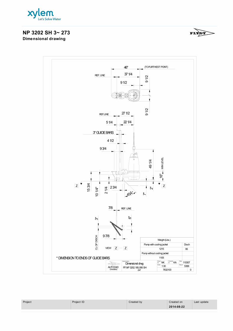
NP 3202 SH 3~ 273Dimensional drawing
FP,NP 3202.185,095 SH
* DIMENSION TO ENDS OF GUIDE BARS
REF.LINE
(TO FURTHEST POINT)
REF. LINE
REF. LINE
CL
OF
DIS
CH
Z Z
Z Z
MIN
LE
VE
L
1105
Pump without cooling jacket
1215
Pump with cooling jacket
Weight (Lbs.)
Disch
cale S
Drawn
Reg no
Date by Checked
by
DRAWING AUTOCAD
Denomination
Dimensional drwg
7632100 0
5399
110307NK KA
1:30
Ø4"
95
22 1/4
27 1/2
4 1/2
3" GUIDE BARS
49 1
/4
7"
2"
16"
2 1/
4
10 1
/4* 2 3/4
9 7/8
6" 3"
9 1/
2 9
1/2
9 1/2
37 1/4
46"
9 3/4
45°
7/8
5 1/4
15 3
/4
VIEW
Last updateCreated on
2014-08-22
Created byProject IDProject