ADAPTOR REDUCER 737 - cmp-products.com Sheets/737.pdf · cmp cable & conduit accessories cmp...
3
www.cmp-products.com CMP CABLE & CONDUIT ACCESSORIES CMP CMP PRODUCTS CABLE GLAND ACCESSORY CATALOGUE TDS500 ISSUE7 06/16 1-3 TECHNICAL DATA Design Specification BS 6121:Part 1:1989, IEC 62444, EN 62444 Enclosure Protection IK10 to IEC 62262 (20 joules) Brass & Stainless Steel Only ATEX Certificate SIRA13ATEX1265X Code of Protection ^ II 2G Ex d IIC Gb, Ex e IIC Gb, II 1D Ex ta IIIC Da ^ IM2 Ex d I Mb, Ex e I Mb (II 2G Ex e IIC Gb, II 1D Ex ta IIIC Da only on Nylon version) Compliance Standards EN 60079-0,1,7,31 IECEx Certificate IECEx SIR13.0094X Code of Protection Ex d I Mb, Ex e I Mb, Ex d IIC Gb, Ex e IIC Gb, Ex ta IIIC Da (Ex e IIC Gb , Ex ta IIIC Da only on nylon version) Compliance Standards IEC 60079-0,1,7,31 cCSAus Certificate 1055233 Code of Protection Class I, Groups A, B, C and D; IP66, 67, 68; Enclosure Type 4X; Class II groups E, F and G; Class III, Ex de II, Class I, Zone 1, AEx de II; (Not available in Nylon) Compliance Standards C22.2 No.0, 0.5, 30, 94,CAN/CSA E60079-0,1, 7, CAN-CSA E61241-1, UL50 Edition 11, UL1203 Edition 4, UL 60079-0,1,7 UL Certificate E214221 (Reducers with NPT or Metric Threads only) Code of Protection Class I Groups A,B,C,D; Class II Groups E,F,G; Class III Compliance Standards UL 1203 EAC Certificate (Formerly GOST R, K & B) TC RU C-GB.ГБ05.B00138 KCS Certificate 14-GA4BO-0249X CCOE / PESO (India) Certificate P333688 NEPSI Certificate GYJ13.1142X Compliance Standards GB3836.1, 2, 3 INMETRO Approval TÜV 12.1332X RETIE Approval 03866 Marine Approvals LRS: 01/00173 (E1), ABS: 01-LD234401C/2-PDA, Continuous Operating Temperature -60°C to +200°C (Metallic), -20°C to +60°C (Nylon) Ingress Protection Rating IP66, IP67 & IP68 (when fitted with CMP sealing accessories) Available Materials Electroless Nickel Plated Brass, Brass, Nylon, Stainless Steel, Aluminium HOW TO ORDER e.g. 737-D-M-2-M-3-4 = Dual Certified Ex d & Ex e – M20 (M) x M25 (F) - Stainless Steel Please refer to Ordering Guide Tables for reference definitions, denoting material variants. When ordering please notify CMP Products in your order if alternative approval markings are required. When ordering Adaptors & Reducers always state the Male Thread size first. Other Thread Variations are available on request. Please refer to Table C on page 139. It should be noted that when using CMP Type 737 Thread Conversion Adaptors and Reducers in association with Explosion Protected electrical equipment the following basic rules must be observed in line with good engineering practice: 1. For direct entry Ex d applications, only adaptor or reducer should be used per cable entry. 2. The female connection thread of a Thread Conversion Adaptor shall “step” not more than two “size” up in the case of a thread gender change. Example; M20 (M) to M32 (F) or M20 (M) to 1” NPT (F) is permitted. Whereas M20 (M) to M40 (F) or M20 (M) to 1-1/2” NPT (F) is not permitted. ADAPTOR REDUCER CMP 737 Adaptor CMP 737 Reducer 737 737 Adaptors & Reducers, Globally Approved, Explosive Atmosphere Cable / Conduit Accessory • Used for thread conversion • Wide range of thread types & sizes • General purpose / industrial version available • Equipment interface ‘O’ ring seal available • -60˚C to +200˚C (metallic versions) • Globally marked, IECEx, ATEX, UL & cCSAus
Transcript of ADAPTOR REDUCER 737 - cmp-products.com Sheets/737.pdf · cmp cable & conduit accessories cmp...
www.cmp-products.com
CMP
CABL
E &
CO
ND
UIT
ACC
ESSO
RIES
CMP CMP PRODUCTS CABLE GLAND ACCESSORY CATALOGUE
TDS500 ISSUE7 06/16 1-3
TECHNICAL DATA
Design Specification BS 6121:Part 1:1989, IEC 62444, EN 62444
Enclosure Protection IK10 to IEC 62262 (20 joules) Brass & Stainless Steel Only
ATEX Certificate SIRA13ATEX1265X
Code of Protection ^ II 2G Ex d IIC Gb, Ex e IIC Gb, II 1D Ex ta IIIC Da^ IM2 Ex d I Mb, Ex e I Mb (II 2G Ex e IIC Gb, II 1D Ex ta IIIC Da only on Nylon version)
Compliance Standards EN 60079-0,1,7,31
IECEx Certificate IECEx SIR13.0094X
Code of ProtectionEx d I Mb, Ex e I Mb, Ex d IIC Gb, Ex e IIC Gb, Ex ta IIIC Da (Ex e IIC Gb , Ex ta IIIC Da only on nylon version)
Compliance Standards IEC 60079-0,1,7,31
cCSAus Certificate 1055233
Code of ProtectionClass I, Groups A, B, C and D; IP66, 67, 68; Enclosure Type 4X; Class II groups E, F and G; Class III, Ex de II, Class I, Zone 1, AEx de II;(Not available in Nylon)
Compliance StandardsC22.2 No.0, 0.5, 30, 94,CAN/CSA E60079-0,1, 7, CAN-CSA E61241-1, UL50 Edition 11, UL1203 Edition 4, UL 60079-0,1,7
UL Certificate E214221 (Reducers with NPT or Metric Threads only)
Code of Protection Class I Groups A,B,C,D; Class II Groups E,F,G; Class III
Compliance Standards UL 1203
EAC Certificate (Formerly GOST R, K & B)
TC RU C-GB.ГБ05.B00138
KCS Certificate 14-GA4BO-0249X
CCOE / PESO (India) Certificate P333688
NEPSI Certificate GYJ13.1142X
Compliance Standards GB3836.1, 2, 3
INMETRO Approval TÜV 12.1332X
RETIE Approval 03866
Marine Approvals LRS: 01/00173 (E1), ABS: 01-LD234401C/2-PDA,
Continuous Operating Temperature -60°C to +200°C (Metallic), -20°C to +60°C (Nylon)
Ingress Protection Rating IP66, IP67 & IP68 (when fitted with CMP sealing accessories)
Available Materials Electroless Nickel Plated Brass, Brass, Nylon, Stainless Steel, Aluminium
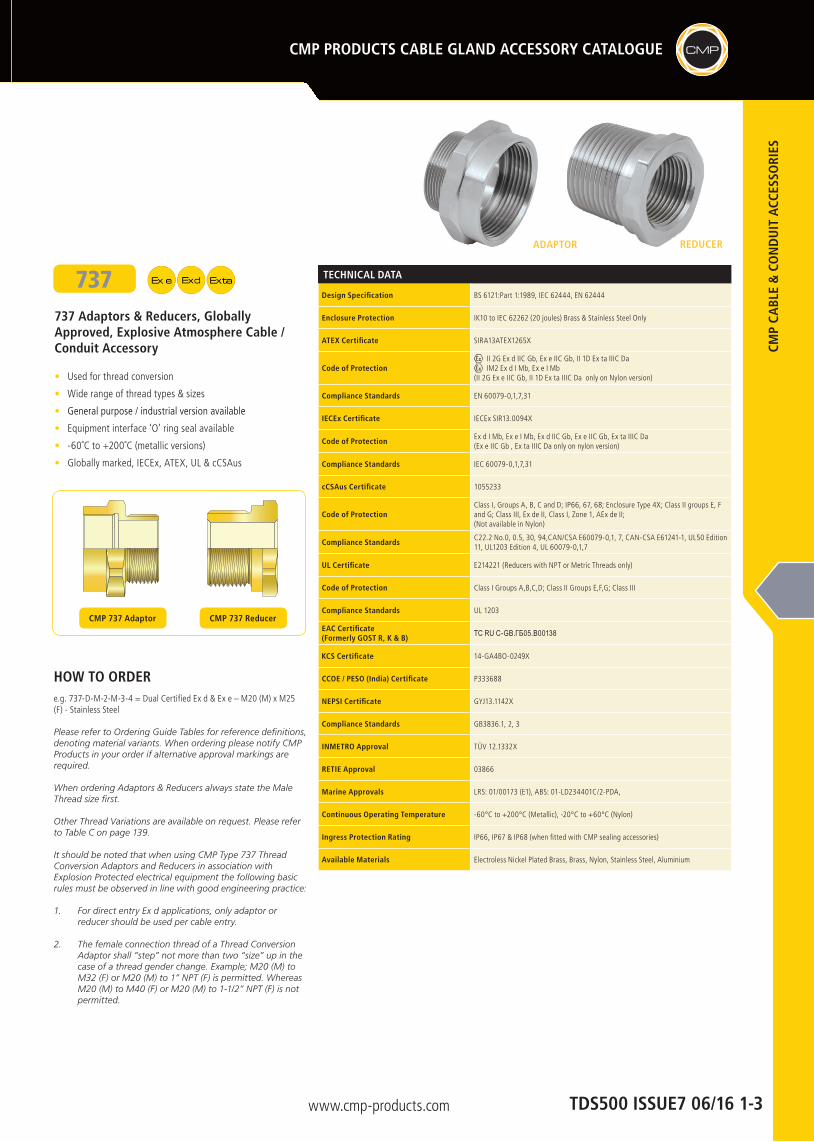
HOW TO ORDERe.g. 737-D-M-2-M-3-4 = Dual Certified Ex d & Ex e – M20 (M) x M25 (F) - Stainless Steel
Please refer to Ordering Guide Tables for reference definitions, denoting material variants. When ordering please notify CMP Products in your order if alternative approval markings are required.
When ordering Adaptors & Reducers always state the Male Thread size first.
Other Thread Variations are available on request. Please refer to Table C on page 139.
It should be noted that when using CMP Type 737 Thread Conversion Adaptors and Reducers in association with Explosion Protected electrical equipment the following basic rules must be observed in line with good engineering practice:
1. For direct entry Ex d applications, only adaptor or reducer should be used per cable entry.
2. The female connection thread of a Thread Conversion Adaptor shall “step” not more than two “size” up in the case of a thread gender change. Example; M20 (M) to M32 (F) or M20 (M) to 1” NPT (F) is permitted. Whereas M20 (M) to M40 (F) or M20 (M) to 1-1/2” NPT (F) is not permitted.
ADAPTOR REDUCER
CMP 737 Adaptor CMP 737 Reducer
737737 Adaptors & Reducers, Globally Approved, Explosive Atmosphere Cable / Conduit Accessory
• Used for thread conversion
• Wide range of thread types & sizes
• General purpose / industrial version available
• Equipment interface ‘O’ ring seal available
• -60˚C to +200˚C (metallic versions)
• Globally marked, IECEx, ATEX, UL & cCSAus
www.cmp-products.com
CMP
CABL
E &
CO
ND
UIT
ACC
ESSO
RIES
CMP CMP PRODUCTS CABLE GLAND ACCESSORY CATALOGUE
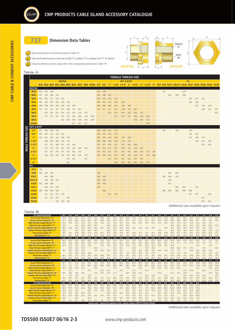
Dimension Data Tables
MA
LE T
HRE
AD
SIZ
E
FEMALE THREAD SIZEMETRIC NPT & BSPP PG
M16 M20 M25 M32 M40 M50 M63 M75 M90 M100 1/2” 3/4” 1” 1-1/4” 1-1/2” 2” 2-1/2” 3” 3-1/2” 4” PG7 PG9 PG11 PG13.5 PG16 PG21 PG29 PG36 PG42 PG48
METRICM16 A01 A03 A09 A02 A09 A01 A09
M20 R01 A05 A08 A18 A05 A08 A22 A05 A06 A08
M25 R03 R03 A11 A19 A27 R03 A19 A23 A27 A19 A27 A33
M32 R05 R05 R05 A24 A28 A34 R05 R05 A24 A28 A34 A24 A28
M40 R08 R08 R08 R08 A29 A35 A49 R08 R08 R08 A30 A35 A49 A29 A35 A39
M50 R11 R11 R11 R11 R11 A38 A51 A61 R11 R11 R11 R11 A38 A47 A61 A38 A42 A47
M63 R14 R14 R14 R14 R14 A53 A56 A72 R14 R14 R14 A53 A63 A72 A53
M75 R17 R17 R17 R17 R17 R16 A69 A74 A78 R17 R17 R17 A65 A74 A83
M90 R20 R20 R18 R20 A76 A80 R19 A75 A79
M100 R21 R21 R21 A79
NPT & BSPP
1/2” R01 A06 A08 A18 A06 A08 A22 A25 A03 A05 A18
3/4” R03 R04 A19 A23 A31 R03 A14 A23 A27 A19 A27
1” R05 R05 R05 A21 A28 A34 R05 R05 A24 A28 A34 A48 A21 A28 A34
1-1/4” R08 R08 R08 A29 A35 R08 R08 R08 A29 A35 A43 A29 A35 A39
1-1/2” R11 R11 R09 R12 A37 A50 R11 R11 R10 R11 A37 A44 A60 A37 A40
2” R13 R13 R13 R13 R13 A52 A62 A70 R13 R13 R13 R12 R14 A52 A55 A70
2-1/2” R17 R17 R17 R17 R16 R16 A57 R17 R17 R17 R17 R17 R17 A64 A73 A77 A81
3” R18 R20 R20 R18 R20 R20 R20 A75 R18 R18 R19 R19 R19 R19 R20 A71 A79 A82
3-1/2” R21 R21 R21 R21 R21 R21 R21 R21 R21
4” R22 R22 R22 R22 R22 R23 R22
PG
PG7 A02
PG9 A03 A03 A09 A03 A03 A03
PG11 A05 A08 A05 A08 A05 A04 A05
PG13.5 A05 A08 A22 A06 A08 A05
PG16 R02 A06 A08 A10 A10 A13
PG21 R03 A17 A23 R05 R05 R05 A27
PG29 R08 R08 R08 R08 R08 R08 R08 R08 R08 R08
PG36 R11 R11 R11 A35 R11 R11 R11 R11 A39
PG42 R12 R12 R12 A52 R12
PG48 R13 R13 R13 R13 R13
Table AF F
D E CC
G
B
AMALE
(M)
FEMALE (F)
F F
D E CC
G
B
AMALE
(M)
FEMALE (F)
REDUCERADAPTORF F
D E CC
G
B
AMALE
(M)
FEMALE (F)
737
Table B737 ADAPTOR DETAIL A01 A02 A03 A04 A05 A06 A07 A08 A09 A10 A11 A12 A13 A14 A15 A16 A17 A18 A19 A20 A21 A22 A23 A24 A25
Across Flats Dimension “A” 22.0 24.0 24.0 24.0 24.0 27.0 28.0 30.0 30.0 30.0 30.0 31.5 31.5 31.5 31.5 33.0 33.0 36.0 36.0 36.0 36.0 41.0 41.0 41.0 46.0Across Corners Diameter “B” 24.2 26.4 26.4 26.4 26.4 29.7 30.8 33.0 33.0 33.0 33.0 34.7 34.7 34.7 34.7 36.3 36.3 39.6 39.6 39.6 39.6 45.1 45.1 45.1 50.6
Male Thread Length (Metric) “C” 15.0 15.0 15.0 15.0 15.0 15.0 15.0 15.0 15.0 15.0 15.0 15.0 15.0 15.0 15.0 15.0 15.0 15.0 15.0 15.0 15.0 15.0 15.0 15.0 -Male Thread Length (NPT) “C” 20.5 - 20.5 20.5 20.5 20.5 - 20.5 20.5 20.5 20.5 - - - - - - 20.5 20.5 20.5 25.3 20.5 20.5 20.5 20.2
Female Thread Length (Metric) “D” 16.0 16.0 16.0 16.0 16.0 16.0 16.0 16.0 16.0 16.0 16.0 16.0 16.0 16.0 16.0 - 16.0 16.0 16.0 16.0 16.0 16.0 16.0 16.0 -Female Thread Length (NPT) “D” 16.0 - 16.0 16.0 16.0 16.0 - 16.0 16.0 16.0 16.0 - - - - 16.0 - 16.0 16.0 16.0 16.0 16.0 16.0 16.0 17.0
Protrusion Length “F” 19.7 19.7 20.8 19.8 21.9 21.9 19.7 20.3 19.8 19.8 19.7 19.4 21.5 19.7 24.7 19.8 19.8 20.0 19.7 19.7 19.7 19.7 20.0 20.2 21.1Nominal Bore “G” 9.7 8.5 10.0 13.0 13.5 13.2 14.0 13.5 8.8 16.0 19.0 11.8 14.3 20.0 20.0 16.0 20.0 14.0 20.0 22.0 26.0 14.0 20.0 26.0 14.0
A26 A27 A28 A29 A30 A31 A32 A33 A34 A35 A36 A37 A38 A39 A40 A41 A42 A43 A44 A45 A46 A47 A48 A49 A50Across Flats Dimension “A” 46.0 46.0 46.0 46.0 46.0 50.0 50.0 55.0 55.0 55.0 55.0 55.0 55.0 60.0 60.0 60.0 60.0 65.0 65.0 65.0 65.0 65.0 70.1 70.1 70.1
Across Corners Diameter “B” 50.6 50.6 50.6 50.6 50.6 55.0 55.0 60.5 60.5 60.5 60.5 60.5 60.5 66.0 66.0 66.0 66.0 71.5 71.5 71.5 71.5 71.5 77.1 77.1 77.1Male Thread Length (Metric) “C” 15.0 15.0 15.0 15.0 15.0 - 15.0 15.0 15.0 15.0 15.0 17.3 15.0 15.0 15.0 15.0 15.0 15.0 - - - 15.0 - 15.0 -
Male Thread Length (NPT) “C” - 20.5 25.3 25.9 - 20.8 - - 25.3 26.2 - 26.4 - 25.9 26.4 - - 25.9 26.4 27.2 27.2 - 25.3 - 26.4Female Thread Length (Metric) “D” 16.0 16.0 16.0 16.0 - 17.0 16.0 16.0 16.0 16.0 - 16.0 16.0 16.0 16.0 16.0 16.0 17.0 17.0 - 16.0 16.0 16.0 16.0 -
Female Thread Length (NPT) “D” - 16.0 16.0 16.0 16.0 - - - 16.0 16.0 17.0 16.0 16.0 15.0 17.0 - - 17.0 17.0 17.0 - 16.0 17.0 17.0 16.0Protrusion Length “F” 20.2 20.7 21.2 21.0 19.5 20.8 28.6 19.7 21.3 25.9 19.7 21.0 22.0 19.7 19.7 19.9 19.7 21.4 20.0 20.4 18.9 22.0 22.7 20.5 19.7
Nominal Bore “G” 19.0 20.0 26.0 31.8 34.5 20.0 32.0 26.0 26.0 31.7 34.0 37.7 43.6 32.0 37.0 39.7 42.0 32.0 37.7 40.5 43.0 44.2 26.0 32.0 38.0A51 A52 A53 A54 A55 A56 A57 A58 A59 A60 A61 A62 A63 A64 A65 A66 A67 A68 A69 A70 A71 A72 A73 A74 A75
Across Flats Dimension “A” 70.1 70.1 70.1 75.0 79.0 79.0 79.0 79.0 80.0 80.0 80.0 80.0 80.0 80.0 80.0 84.0 84.0 84.0 84.0 95.0 95.0 100.0 100.0 100.0 100.0Across Corners Diameter “B” 77.1 77.1 77.1 82.5 86.9 86.9 86.9 86.9 88.0 88.0 88.0 88.0 88.0 88.0 88.0 92.4 92.4 92.4 92.4 104.5 104.5 110.0 110.0 110.0 110.0
Male Thread Length (Metric) “C” 15.0 15.0 15.0 15.0 - 15.0 - - 15.0 - 15.0 - 15.0 - 15.0 15.0 19.3 15.0 15.0 - - 15.0 - 15.0 20.0Male Thread Length (NPT) “C” - 27.2 - - 27.2 - 40.2 20.3 - 26.4 - 27.2 - 40.2 - - - - - 27.2 41.8 - 40.2 - 41.8
Female Thread Length (Metric) “D” 16.0 16.0 16.0 16.0 - 17.0 16.0 17.0 21.3 - 16.0 16.0 16.0 - - 17.0 - 21.3 16.3 23.0 - 14.3 - 18.0 16.0Female Thread Length (NPT) “D” - 17.0 17.0 - 23.0 - - - - 23.0 - 23.0 - 23.0 23.0 - 23.3 - - 25.0 29.7 25.0 25.0 - 36.5
Protrusion Length “F” 19.5 20.5 19.7 19.7 27.6 19.5 19.7 20.5 28.9 27.6 19.5 19.7 27.3 28.9 27.3 19.7 28.9 28.9 21.3 30.0 29.7 30.0 30.3 24.0 51.2Nominal Bore “G” 44.2 49.0 53.0 55.0 49.0 53.0 60.0 63.0 26.4 38.0 42.0 49.0 55.0 60.5 65.0 53.0 60.7 62.5 68.0 49.0 75.0 55.0 60.5 64.8 75.0
737 REDUCER DETAIL R01 R02 R03 R04 R05 R06 R07 R08 R09 R10 R11 R12 R13 R14 R15 R16 R17 R18 R19 R20 R21 R22 - - -Across Flats Dimension “A” 24.0 27.0 30.0 30.0 36.0 37.5 41.0 46.0 50.0 51.8 55.0 60.0 65.0 70.1 75.0 79.0 80.0 95.0 99.0 100.0 110.0 123.2 - - -
Across Corners Diameter “B” 26.4 29.7 33.0 33.0 39.6 41.3 50.6 50.6 55.0 57.0 60.5 66.0 71.5 77.1 82.5 86.9 88.0 104.5 108.9 110.0 121.0 135.5 - - -Male Thread Length (Metric) “C” 15.0 15.0 15.0 - 18.3 15.0 15.0 15.6 15.0 - 16.3 15.0 15.0 15.0 15.0 15.0 15.0 25.3 20.0 20.0 20.0 36.8 - - -
Male Thread Length (NPT) “C” 20.5 20.5 20.5 20.5 25.3 - - 25.9 26.4 26.4 26.4 26.4 27.2 27.2 - 40.2 40.2 41.8 41.8 41.8 43.1 44.3Female Thread Length (Metric) “D” 24.3 24.3 24.0 26.3 24.0 24.3 24.3 24.3 24.3 - 24.3 24.3 25.3 25.0 25.3 25.3 24.3 35.3 - 30.0 30.0 46.8 - - -
Female Thread Length (NPT) “D” 29.5 - 29.5 - 16.0 - - 16.0 16.0 16.0 16.0 16.0 16.0 16.0 - 50.2 35.3 16.0 16.0 35.3 16.0 17.0Protrusion Length “F” 9.3 9.3 9.3 10.6 10.3 9.3 9.3 9.3 10.3 9.3 10.3 9.3 10.3 10.3 10.3 10.3 10.3 10.3 10.3 10.3 11.3 11.3 - - -
please note - Figures for guidance only - please contact CMP for further details
Select male thread on the left hand column of table “A”
Select the female thread size at the top of table “A”, prefixed “A” for Adaptor and “R” for Reducer
Using this reference number, please refer to the corresponding dimensions in Table “B”
1
3
2
Additional sizes available upon request
Additional sizes available upon request
TDS500 ISSUE7 06/16 2-3
www.cmp-products.com
CMP
CABL
E &
CO
ND
UIT
ACC
ESSO
RIES
CMP CMP PRODUCTS CABLE GLAND ACCESSORY CATALOGUE
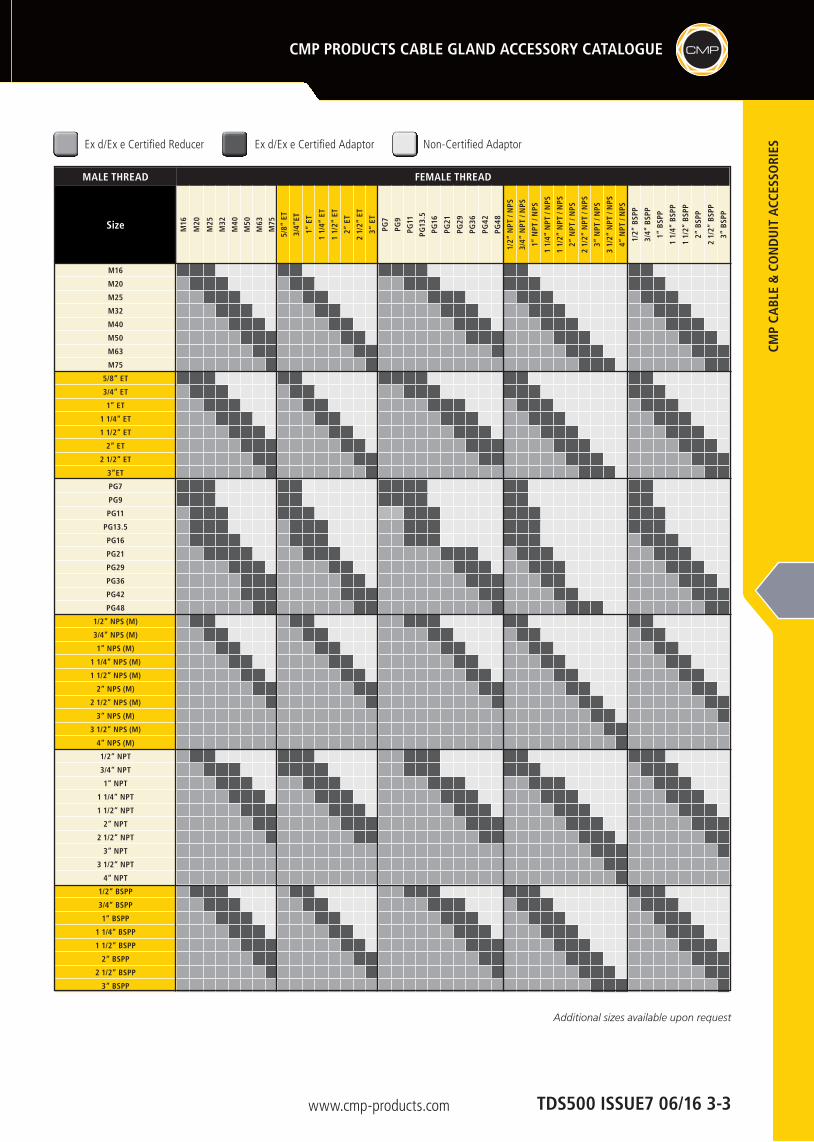
MALE THREAD FEMALE THREAD
Size M16
M20
M25
M32
M40
M50
M63
M75
5/8”
ET
3/4”
ET
1” E
T
1 1/
4” E
T
1 1/
2” E
T
2” E
T
2 1/
2” E
T
3” E
T
PG7
PG9
PG11
PG13
.5
PG16
PG21
PG29
PG36
PG42
PG48
1/2”
NPT
/ N
PS
3/4”
NPT
/ N
PS
1” N
PT /
NPS
1 1/
4” N
PT /
NPS
1 1/
2” N
PT /
NPS
2” N
PT /
NPS
2 1/
2” N
PT /
NPS
3” N
PT /
NPS
3 1/
2” N
PT /
NPS
4” N
PT /
NPS
1/2”
BSP
P
3/4”
BSP
P
1” B
SPP
1 1/
4” B
SPP
1 1/
2” B
SPP
2” B
SPP
2 1/
2” B
SPP
3” B
SPP
M16
M20
M25
M32
M40
M50
M63
M75
5/8” ET
3/4” ET
1” ET
1 1/4” ET
1 1/2” ET
2” ET
2 1/2” ET
3”ET
PG7
PG9
PG11
PG13.5
PG16
PG21 PG29
PG36
PG42
PG48
1/2” NPS (M)
3/4” NPS (M)
1” NPS (M)
1 1/4” NPS (M)
1 1/2” NPS (M)
2” NPS (M)
2 1/2” NPS (M)
3” NPS (M)
3 1/2” NPS (M)
4” NPS (M)
1/2” NPT
3/4” NPT
1” NPT
1 1/4” NPT
1 1/2” NPT
2” NPT
2 1/2” NPT
3” NPT
3 1/2” NPT
4” NPT
1/2” BSPP
3/4” BSPP
1” BSPP
1 1/4” BSPP
1 1/2” BSPP
2” BSPP
2 1/2” BSPP
3” BSPP
Ex d/Ex e Certified Reducer Non-Certified AdaptorEx d/Ex e Certified Adaptor
Additional sizes available upon request
TDS500 ISSUE7 06/16 3-3