Adaptive Millimeter Wave Beam Alignment for Dual-Polarized ... · SONG et al.: ADAPTIVE MILLIMETER...
14
IEEE TRANSACTIONS ON WIRELESS COMMUNICATIONS, VOL. 14, NO. 11, NOVEMBER 2015 6283 Adaptive Millimeter Wave Beam Alignment for Dual-Polarized MIMO Systems Jiho Song, Student Member, IEEE, Junil Choi, Member, IEEE, Stephen G. Larew, Student Member, IEEE, David J. Love, Fellow, IEEE, Timothy A. Thomas, Member, IEEE, and Amitabha Ghosh, Fellow, IEEE Abstract—Fifth-generation wireless systems are expected to employ multiple-antenna communication at millimeter wave (mmWave) frequencies using small cells within heterogeneous cellular networks. The high path loss of mmWave and the physical obstructions make communication challenging. To compensate for the severe path loss, mmWave systems may employ a beam align- ment algorithm that facilitates highly directional transmission by aligning the beam direction of multiple antenna arrays. This paper discusses a mmWave system employing dual-polarized antennas. First, we propose a practical soft-decision beam alignment (soft- alignment) algorithm that exploits orthogonal polarizations. By sounding the orthogonal polarizations in parallel, the equality cri- terion of the Welch bound for training sequences is relaxed. Second, the analog beamforming system is adapted to the directional char- acteristics of the mmWave link, assuming a high Ricean K-factor and poor scattering environment. A soft-alignment algorithm en- ables the mmWave system to align a large number of narrow beams to the channel subspace in an attempt to effectively scan the mmWave channel. Third, we propose a method to efficiently adapt the number of channel sounding observations to the specific chan- nel environment based on an approximate probability of beam misalignment. Simulation results show that the proposed soft- alignment algorithm with adaptive sounding time effectively scans the channel subspace of a mobile user by exploiting polarization diversity. Index Terms—Millimeter wave (mmWave) wireless, dual- polarized channel, beam alignment algorithm. I. I NTRODUCTION M ILLIMETER wave (mmWave) multiple-input multiple- output (MIMO) systems are a prime candidate to allow future communication systems to provide the throughput en- hancements needed to meet the expected demands for mobile data [1]–[4]. Radio links operating over the wide bandwidths available in the mmWave spectrum are a promising solution for providing access for small cells within heterogeneous cellular networks. When compared to lower frequencies, the higher Manuscript received August 6, 2014; revised January 10, 2015 and May 12, 2015; accepted June 8, 2015. Date of publication July 2, 2015; date of current version November 9, 2015. This work was supported in part by Nokia Networks and the National Science Foundation Graduate Research Fellowship Program under Grant No. DGE-1333468. The associate editor coordinating the review of this paper and approving it for publication was A. Zajic. J. Song, S. G. Larew, and D. J. Love are with the School of Electrical and Computer Engineering, Purdue University, West Lafayette, IN 47907 USA (e-mail: [email protected]; [email protected]; [email protected]). J. Choi is with the Wireless Networking and Communications Group, The University of Texas at Austin, Austin, TX 78712 USA (e-mail: junil.choi@ utexas.edu). T. A. Thomas and A. Ghosh are with Nokia Networks, Arlington Heights, IL 60004 USA (e-mail: [email protected]; [email protected]). Color versions of one or more of the figures in this paper are available online at http://ieeexplore.ieee.org. Digital Object Identifier 10.1109/TWC.2015.2452263 expected path loss of mmWave requires greater system gains in the link budget [2], which may be attained via beamform- ing with multiple antenna systems. The small wavelength of mmWaves allows for a dense packing of many antennas in a small space. In effect, a steerable, phased-array architecture of many antennas can be controlled to form high-gain directional transmissions. However, mmWave systems may have only a small number of radio frequency (RF) chains due to their high cost and power utilization. Therefore, beamforming in mmWave systems is performed mainly by using inexpensive RF phase shifters in the analog domain [4]. In contrast to conventional cellular systems using one RF chain per antenna, analog beamformed mmWave systems can- not observe the channel of each receive antenna directly since the incident waves at each antenna are combined in the analog domain. Moreover, the large number of antennas and the high path loss at mmWave frequencies make it difficult to acquire enough samples to compute meaningful channel estimates for each receive antenna. Instead, one approach is to perform subspace sampling using a finite number of training vectors for beam alignment. The training vectors are designed to sound the mmWave channel in an attempt to align the beamformers to the channel subspace. Several beam alignment techniques for mmWave systems have been developed based on hard-decision beam alignment (hard-alignment) techniques [5]–[9]. In the hard-alignment al- gorithms, a set of candidate training vectors are used to scan the channel subspace. The chosen beamformer for data trans- mission comes from the same set used for channel subspace scanning. Hard-alignment sampling algorithms utilizing a hi- erarchical multi-round beam search approach are studied for uniform linear array (ULA) scenarios in [5], [6] and extended to dual-polarized arrays in [8], [9], which show better perfor- mance than the standardized technique in [7]. However, the hard-alignment techniques have fundamental limits on beam alignment performance. In low signal-to-noise ratio (SNR) environments, the hard-alignment techniques exhibit a high probability of beam misalignment. Dual-polarized antenna systems, discussed in [10]–[15], are expected to be incorporated with mmWave systems. From a signal processing point-of-view, the orthogonal polarizations relax the Welch bound conditions that constrain the channel sounding time. Each desired polarization can be decoupled independently by using reference signal (RS) sequences which are designed to support high rank transmission in systems such as LTE and LTE-Advanced [16]–[18]. Numerous advantages exist, including the ability to sound the orthogonal polarizations 1536-1276 © 2015 IEEE. Personal use is permitted, but republication/redistribution requires IEEE permission. See http://www.ieee.org/publications_standards/publications/rights/index.html for more information.
Transcript of Adaptive Millimeter Wave Beam Alignment for Dual-Polarized ... · SONG et al.: ADAPTIVE MILLIMETER...

IEEE TRANSACTIONS ON WIRELESS COMMUNICATIONS, VOL. 14, NO. 11, NOVEMBER 2015 6283
Adaptive Millimeter Wave Beam Alignmentfor Dual-Polarized MIMO Systems
Jiho Song, Student Member, IEEE, Junil Choi, Member, IEEE, Stephen G. Larew, Student Member, IEEE,David J. Love, Fellow, IEEE, Timothy A. Thomas, Member, IEEE, and Amitabha Ghosh, Fellow, IEEE
Abstract—Fifth-generation wireless systems are expected toemploy multiple-antenna communication at millimeter wave(mmWave) frequencies using small cells within heterogeneouscellular networks. The high path loss of mmWave and the physicalobstructions make communication challenging. To compensate forthe severe path loss, mmWave systems may employ a beam align-ment algorithm that facilitates highly directional transmission byaligning the beam direction of multiple antenna arrays. This paperdiscusses a mmWave system employing dual-polarized antennas.First, we propose a practical soft-decision beam alignment (soft-alignment) algorithm that exploits orthogonal polarizations. Bysounding the orthogonal polarizations in parallel, the equality cri-terion of the Welch bound for training sequences is relaxed. Second,the analog beamforming system is adapted to the directional char-acteristics of the mmWave link, assuming a high Ricean K-factorand poor scattering environment. A soft-alignment algorithm en-ables the mmWave system to align a large number of narrowbeams to the channel subspace in an attempt to effectively scan themmWave channel. Third, we propose a method to efficiently adaptthe number of channel sounding observations to the specific chan-nel environment based on an approximate probability of beammisalignment. Simulation results show that the proposed soft-alignment algorithm with adaptive sounding time effectively scansthe channel subspace of a mobile user by exploiting polarizationdiversity.
Index Terms—Millimeter wave (mmWave) wireless, dual-polarized channel, beam alignment algorithm.
I. INTRODUCTION
M ILLIMETER wave (mmWave) multiple-input multiple-output (MIMO) systems are a prime candidate to allow
future communication systems to provide the throughput en-hancements needed to meet the expected demands for mobiledata [1]–[4]. Radio links operating over the wide bandwidthsavailable in the mmWave spectrum are a promising solution forproviding access for small cells within heterogeneous cellularnetworks. When compared to lower frequencies, the higher
Manuscript received August 6, 2014; revised January 10, 2015 and May 12,2015; accepted June 8, 2015. Date of publication July 2, 2015; date of currentversion November 9, 2015. This work was supported in part by Nokia Networksand the National Science Foundation Graduate Research Fellowship Programunder Grant No. DGE-1333468. The associate editor coordinating the reviewof this paper and approving it for publication was A. Zajic.
J. Song, S. G. Larew, and D. J. Love are with the School of Electricaland Computer Engineering, Purdue University, West Lafayette, IN 47907 USA(e-mail: [email protected]; [email protected]; [email protected]).
J. Choi is with the Wireless Networking and Communications Group, TheUniversity of Texas at Austin, Austin, TX 78712 USA (e-mail: [email protected]).
T. A. Thomas and A. Ghosh are with Nokia Networks, Arlington Heights, IL60004 USA (e-mail: [email protected]; [email protected]).
Color versions of one or more of the figures in this paper are available onlineat http://ieeexplore.ieee.org.
Digital Object Identifier 10.1109/TWC.2015.2452263
expected path loss of mmWave requires greater system gainsin the link budget [2], which may be attained via beamform-ing with multiple antenna systems. The small wavelength ofmmWaves allows for a dense packing of many antennas in asmall space. In effect, a steerable, phased-array architecture ofmany antennas can be controlled to form high-gain directionaltransmissions. However, mmWave systems may have only asmall number of radio frequency (RF) chains due to theirhigh cost and power utilization. Therefore, beamforming inmmWave systems is performed mainly by using inexpensiveRF phase shifters in the analog domain [4].
In contrast to conventional cellular systems using one RFchain per antenna, analog beamformed mmWave systems can-not observe the channel of each receive antenna directly sincethe incident waves at each antenna are combined in the analogdomain. Moreover, the large number of antennas and the highpath loss at mmWave frequencies make it difficult to acquireenough samples to compute meaningful channel estimates foreach receive antenna. Instead, one approach is to performsubspace sampling using a finite number of training vectors forbeam alignment. The training vectors are designed to sound themmWave channel in an attempt to align the beamformers to thechannel subspace.
Several beam alignment techniques for mmWave systemshave been developed based on hard-decision beam alignment(hard-alignment) techniques [5]–[9]. In the hard-alignment al-gorithms, a set of candidate training vectors are used to scanthe channel subspace. The chosen beamformer for data trans-mission comes from the same set used for channel subspacescanning. Hard-alignment sampling algorithms utilizing a hi-erarchical multi-round beam search approach are studied foruniform linear array (ULA) scenarios in [5], [6] and extendedto dual-polarized arrays in [8], [9], which show better perfor-mance than the standardized technique in [7]. However, thehard-alignment techniques have fundamental limits on beamalignment performance. In low signal-to-noise ratio (SNR)environments, the hard-alignment techniques exhibit a highprobability of beam misalignment.
Dual-polarized antenna systems, discussed in [10]–[15], areexpected to be incorporated with mmWave systems. From asignal processing point-of-view, the orthogonal polarizationsrelax the Welch bound conditions that constrain the channelsounding time. Each desired polarization can be decoupledindependently by using reference signal (RS) sequences whichare designed to support high rank transmission in systems suchas LTE and LTE-Advanced [16]–[18]. Numerous advantagesexist, including the ability to sound the orthogonal polarizations
1536-1276 © 2015 IEEE. Personal use is permitted, but republication/redistribution requires IEEE permission.See http://www.ieee.org/publications_standards/publications/rights/index.html for more information.
6284 IEEE TRANSACTIONS ON WIRELESS COMMUNICATIONS, VOL. 14, NO. 11, NOVEMBER 2015
in parallel for channel training, multiplex information acrossthe polarizations, and obtain a high level of immunity to po-larization mismatch between the base station and the mobileuser. Furthermore, a dual-polarized system may be more spaceefficient, allowing more antennas in a small form factor. To thebest of our knowledge, outdoor mmWave systems over dual-polarized channels have not been reported yet except in ourprevious work [8], [9].
For connecting small cells and mobile users, we consider ammWave system employing dual-polarized antennas. To alignthe beam direction of a large number of antennas, we develop abeam alignment algorithm that operates well even in a low SNRregime. First, with a simplified, dual-polarized channel model,an optimal set of combining and beamforming vectors at base-band and an analog beamforming vector under perfect channelstate information (CSI) are discussed in order to provide crite-ria for practical combining and beamforming solutions. Then,we propose a soft-decision beam alignment (soft-alignment)algorithm that exploits the dual-polarized channel. Based onmaximum likelihood estimation (MLE), the beam alignmentalgorithm estimates the channel subspace given our channelmodel assumptions, which consist of a sub-channel vectorand a block matrix corresponding to propagation between twopolarizations. One stage of sampling is performed, followedby a post-processing stage consisting of two rounds of beamalignment. Based on the rough beam direction of the sub-channel vector estimated in the first round, a more accuratebeam direction is estimated in the second round.
Our second contribution is an adaptive algorithm that se-lects the sounding time efficiently. We derive an approximateprobability of beam misalignment based on a beam patternanalysis of the codebook used for beam alignment. With thisapproximate probability, the system is able to choose an ef-ficient number of channel samples in order to ensure lowprobability of beam misalignment. Based on the formulation,the system changes the appropriate sounding time adaptivelyaccording to the channel environment to satisfy a predefinedcriterion. Despite the severe path loss at mmWave frequencies,the proposed algorithm effectively scans the channel subspacewith the minimum necessary number of sounding samples.
In Section II, we describe a mmWave system employ-ing dual-polarized antennas. In Section III, a practical soft-alignment algorithm is proposed for dual-polarized mmWavesystems. In Section IV, an adaptive sounding algorithm isdeveloped for the soft-alignment algorithm. In Section V, nu-merical results are presented to verify the performance of theproposed algorithms and Section VI details our conclusions.
Throughout this paper, C denotes the field of complex num-bers, CN denotes the complex normal distribution,N denotes thenormal distribution, [a, b] is the closed interval between a and b,U(a, b) denotes the uniform distribution in the interval [a, b], IN
is the N × N identity matrix, E[·] is the expectation operator, (·)∗is the complex conjugate, (·)H is the conjugate transpose,R(·) isthe real part of complex number, I(·) is the imaginary part ofcomplex number, 1[a,b) is the indicator function, ‖ · ‖p is thep-norm, � is the Hadamard product, ⊗ is the Kronecker product,Aa,b, A(:, a), vec(A), |A| denote (a, b)th entry, ath column vec-tor, vectorization, and cardinality of the matrix A, respectively.
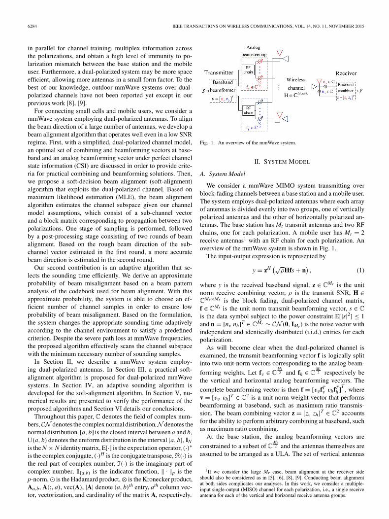
Fig. 1. An overview of the mmWave system.
II. SYSTEM MODEL
A. System Model
We consider a mmWave MIMO system transmitting overblock-fading channels between a base station and a mobile user.The system employs dual-polarized antennas where each arrayof antennas is divided evenly into two groups, one of verticallypolarized antennas and the other of horizontally polarized an-tennas. The base station has Mt transmit antennas and two RFchains, one for each polarization. A mobile user has Mr = 2receive antennas1 with an RF chain for each polarization. Anoverview of the mmWave system is shown in Fig. 1.
The input-output expression is represented by
y = zH (√ρHfs + n), (1)
where y is the received baseband signal, z ∈ CMr is the unitnorm receive combining vector, ρ is the transmit SNR, H ∈CMr×Mt is the block fading, dual-polarized channel matrix,f ∈ CMt is the unit norm transmit beamforming vector, s ∈ C
is the data symbol subject to the power constraint E[|s|2] ≤ 1and n = [nv nh]T ∈ CMr ∼ CN (0, IMr) is the noise vector withindependent and identically distributed (i.i.d.) entries for eachpolarization.
As will become clear when the dual-polarized channel isexamined, the transmit beamforming vector f is logically splitinto two unit-norm vectors corresponding to the analog beam-
forming weights. Let fv ∈ CMt2 and fh ∈ C
Mt2 respectively be
the vertical and horizontal analog beamforming vectors. The
complete beamforming vector is then f = [vvfTv vhfT
h ]T, where
v = [vv vh]T ∈ C2 is a unit norm weight vector that performsbeamforming at baseband, such as maximum ratio transmis-sion. The beam combining vector z = [zv zh]T ∈ C2 accountsfor the ability to perform arbitrary combining at baseband, suchas maximum ratio combining.
At the base station, the analog beamforming vectors are
constrained to a subset of CMt2 and the antennas themselves are
assumed to be arranged as a ULA. The set of vertical antennas
1If we consider the large Mr case, beam alignment at the receiver sideshould also be considered as in [5], [6], [8], [9]. Conducting beam alignmentat both sides complicates our analyses. In this work, we consider a multiple-input single-output (MISO) channel for each polarization, i.e., a single receiveantenna for each of the vertical and horizontal receive antenna groups.
SONG et al.: ADAPTIVE MILLIMETER WAVE BEAM ALIGNMENT FOR DUAL-POLARIZED MIMO SYSTEMS 6285
forms a ULA with uniform element spacing, and the horizontalset is similarly arranged. The ability to control the gain andphase of each antenna at baseband is impractical due to thehigh cost and power consumption of many individual RF chains[5]–[9]. Instead, analog beamforming is performed with RFphase shifters and no gain control [5]. The constrained set ofpossible equal gain beamforming vectors in the N-dimensionalcomplex space is
BN = {w ∈ C
N : (wwH)�,� = 1/N, 1 ≤ � ≤ N}. (2)
B. Dual-Polarized Channel Model
The mmWave channel differs from the conventionalRayleigh channel model, which assumes a rich scattering chan-nel environment, and development of an appropriate modelis necessary [19]–[21]. A general view of the dual-polarizedmmWave channel follows from partitioning the channel into ablock matrix form as
H =[
hHvv hH
vhhH
hv hHhh
](3)
where hab ∈ CMt2 × Mr
2 is a sub-channel vector from polarizationb to a.
A dual-polarized mmWave channel model is proposed in [8].However, this realistic channel model complicates analysis andhence a simpler channel model is needed. Due to the dominantsingle path that is typically observed [20]–[23], we approximatethe mmWave channel with a single path having an angle ofdeparture (AoD) from the base station to the mobile user of θ .Under the assumption that propagation between the differentpolarization pairs only varies by a scalar, the block matrixrepresentation in (3) may be written as
H A ⊗ hH, (4)
where A ∈ CMr×2 is the polarization matrix and h = a Mt2
(θ)
is the array response vector for the single path with AoD θ ∼U(θLB, θUB). The array response vector for a ULA is
AN = {aN(θ) ∈ C
N : θLB ≤ θ ≤ θUB}
(5)
aN(θ) =[1 ej 2πd
λ sin θ · · · ej 2πdλ (N−1) sinθ
]T, (6)
where d is the antenna element spacing and λ is the wavelength.In (4), the polarization matrix A contains the gains and phase
shifts across polarizations as
A =[αvv αvh
αhv αhh
]=[βvv cos ζ −βvh sin ζ
βhv sin ζ βhh cos ζ
],
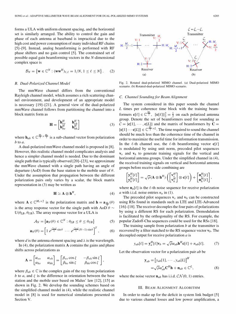
where βab ∈ C is the complex gain of the ray from polarizationb to a, and ζ is the difference in orientation between the basestation and the mobile user based on Malus’ law [12], [15] asshown in Fig. 2. We develop the sounding schemes based onthe simplified channel model in (4), while the realistic channelmodel in [8] is used for numerical simulations presented inSection V.
Fig. 2. Rotated dual-polarized MIMO channel. (a) Dual-polarized MIMOscenario. (b) Rotated-dual-polarized MIMO scenario.
C. Channel Sounding for Beam Alignment
The system considered in this paper sounds the channelL times per coherence time block with the training beam-
formers c[�] ∈ CMt2 , ‖c[�]‖2
2 = 12 on each polarized antenna
group. Denote the set of beamformers used for sounding asC = {c[1], · · · , c[L]} and the matrix of beamformers by C =[c[1] · · · c[L]] ∈ C
Mt2 ×L. The time required to sound the channel
should be much less than the coherence time of the channel inorder to maximize the useful time for information transmission.In the �-th channel use, the �-th beamforming vector c[�]is modulated by using unit norm, precoded pilot sequencesvv and vh to generate training signals for the vertical andhorizontal antenna groups. Under the simplified channel in (4),the received training signals on vertical and horizontal antennagroups before receive side combining are[
yHv [�]
yHh [�]
]= √
ρ(A ⊗ hH)
([vHv
vHh
]⊗ c[�]
)+[
nHv [�]
nHh [�]
],
where na[�] is the �-th noise sequence for receive polarizationa with i.i.d. noise entries na in (1).
The precoded pilot sequences vv and vh can be constructedusing RSs found in standards such as LTE and LTE-Advanced[16]–[18]. The receiver decouples the four pairs of polarizationsby using a different RS for each polarization. Demodulationis facilitated by the orthogonality of the RS. For example, thepopular Zadoff-Chu sequences could be used for the RSs [18].
The training sample from polarization b at the transmitter isrecovered by a filter matched to the RS sequence vector vb. Thedecoupled output for receive polarization a is
yab[�] = yHa [�]vb = √
ραabhHc[�] + nab[�]. (7)
Let the observation vector for a polarization pair ab be
yab = [yab[1], · · · , yab[L]]H
=√ρα∗
abCHh + nab ∈ CL, (8)
where the noise vector nab has i.i.d. CN (0, 1) entries.
III. BEAM ALIGNMENT ALGORITHM
In order to make up for the deficit in system link budget [5]due to various channel losses and low power amplification, a
6286 IEEE TRANSACTIONS ON WIRELESS COMMUNICATIONS, VOL. 14, NO. 11, NOVEMBER 2015
mmWave system must employ beamforming and combining toincrease the effective SNR. However, the method of choosing abeamformer and combiner is non-trivial when the channel is notdirectly observable. Reliable operation of previously proposedbeamforming algorithms [5]–[9] is limited to an unnecessarilyhigh SNR range. Links that would otherwise be possible withgood beamforming gain cannot be formed. The common factorthat limits performance at low SNR is the hard-decision beingmade in the cited algorithms.
It is natural to consider a soft-alignment algorithm to improvebeamforming reliability and performance. Instead of choosingone of the beamformers from the set used for channel sounding(referred to as a hard-alignment), a soft-alignment algorithmmay choose any feasible beamformer. In the hard-alignmentalgorithms, the probability of choosing the optimal beamformeris fundamentally limited by the SNR ρ. More observations leadto a higher probability of choosing a good beamformer, butthe probability of choosing the optimal beamformer in hard-alignment is eventually limited by the SNR and not the numberof observations. On the other hand, the performance of oursoft-alignment algorithm is not fundamentally limited by theSNR and hence can scale with the number of channel soundingobservations.
A. Full CSI Beam Alignment
Before investigating practical mmWave beamforming solu-tions, we pause to consider optimal beamforming vectors underperfect CSI conditions for the simplified channel model in (4).The full CSI beamforming solution gives an upper bound onperformance for practical systems under the assumed systemand channel model, and it offers insight on the design ofpractical beamforming algorithms.
In order to maximize the achievable rate of the system, themagnitude of the effective channel gain should be maximized[24] by choosing optimal beamforming and combining vectors.The maximizers of the effective gain are
(z, f) = arg maxz∈CMr ,f∈CMt
|zHHf|2. (9)
Keep in mind that z and f are unit norm. The solution to (9) iswell known to be the dominant left and right singular vectorsof H. Taking a closer look, the singular value decomposition(SVD) of H is
H = (UA�AVH
A
)⊗ (Uh�hVH
h
)where UA�AVH
A is the SVD of A, and Uh�hVHh is the SVD of
hH . Considering the constraints on the baseband beamformingvector fA, the analog beamforming vector fh, and the channelmodel in (4), the constrained maximizers are
(zA, fA, fh) = arg max(zA,fA,fh)∈C2×C2×BMt
2
∣∣(zHAAfA
)⊗ (hHfh)∣∣2 .
The optimal solutions for zA and fA are the dominant leftand right singular vectors of A, respectively, i.e., zA = UA(:, 1), fA = VA(:, 1), because the combining and beamforming
vectors zA and fA at baseband have no equal gain constraint. Onthe other hand, fh is restricted by the equal gain constraint. Anoptimal solution is fh = h
‖h‖2since h is assumed to be an array
manifold vector in (6), which has equal gain entries.Optimal and feasible combining and beamsteering vectors in
(9) are given by
z = zA, f = fA ⊗ fh. (10)
The unit norm weight vectors z and v that perform combiningand beamforming at baseband and the analog beamformingvectors fv = fh at RF phase shifters on both vertical and hor-izontal antenna groups, defined in the input-output expressionof (1), correspond to zA, fA, and fh in (10), respectively.
The beamformer for a sub-channel vector in the array man-ifold set is better described as a beamsteering vector. Further-more, the algorithm of choosing a good beamsteering vectoris better described as a beam alignment algorithm. When thebeamformer is chosen from the array manifold set, the mainlobe of the gain pattern is being steered to maximize gain in aspecific direction. In effect, narrow beams are created that mustbe aligned to maximize the effective channel gain.
B. Beam Alignment with Noisy Channel Sounding
We now present a beam alignment algorithm that seeks tomaximize the effective channel gain without direct knowledgeof the channel. The general idea is to observe the basebandoutput responses yab in (8) resulting from a set of trainingvectors C = {c[1], · · · , c[L]} and then choose a beamformerin a finite set E = {e1, · · · , eQ} with Q codewords given theobservations.2
1) Limits for Hard-Alignment: Previously proposed hard-alignment algorithms show good performance at high SNR butare unreliable at low SNR [5], [6], [8], [9]. In a hard-alignmentalgorithm, the chosen beamformer is restricted to be one ofthe beamformers used for channel sounding, i.e., E = C. Theestimated beamforming vector f is chosen to be the trainingvector c[�] ∈ C with test sample yab[�] in (7) as
� = arg max�∈{1,...,L}
∣∣√ραabhHc[�] + nab[�]∣∣2
.= arg max�={1,...,L}
∣∣∣mhab[�] + nab[�]
∣∣∣2 , (11)
where mhab[�] denotes the scaled correlation between c[�] and
the sub-channel vector h to be estimated and nab[�] ∼ CN (0, 1)
is additive random noise that hinders good beam alignment.The variance in the estimation of h in (11) is related to the
mean and variance of the test sample yab[�], i.e., E[mhab[�]] and
E[|nhab[�]|
2] = 1. For the best beam alignment, the variance ofthe noise nab[�] should be small in comparison with the powerof mh
ab[�] which is given by∣∣mhab[�]
∣∣2 = ρMt
4|αab|2G[�] ≤ ρMt
4|αab|2, (12)
2The choice of beamformer in E for beam alignment is based on themultilevel codebook in [5], [6].

SONG et al.: ADAPTIVE MILLIMETER WAVE BEAM ALIGNMENT FOR DUAL-POLARIZED MIMO SYSTEMS 6287
where G[�] .= |hHc[�]|2 ≤ 1 is the beamforming gain between
the normalized sub-channel h = h‖h‖2
and the normalized train-
ing vector c[�] = c[�]‖c[�]‖2
using ‖h‖22 = Mt
2 and ‖c[�]‖22 = 1
2 .
Notice that increasing the number of samples L does not in-crease the upper bound. Thus, adaptively choosing L in a hard-alignment algorithm does not help at low SNR, with fixed Mt.
2) Maximum Likelihood Soft-Alignment: In the proposedsoft-alignment algorithm for beam alignment, multiple soundingsamples yab in (8) are considered together, while each soundingsample yab[�] in (7) is considered separately in the hard-alignment algorithm. Specifically, the algorithm chooses thebeamformer in a predefined codebook E that maximizes the like-lihood function of the received samples. In the soft-alignmentalgorithm, training vectors and beamformers do not need to bein the same set, i.e., E �=C, and each set is designed indepen-dently. In contrast, hard-alignment requires E=C. The numberQ of candidate codewords in E may be much larger in size thanthe number of sounding samples L, i.e., Q≥L, whereas Q=Lin hard-alignment. If Q is large, it is possible to utilize a largeset of candidate codewords generating narrow transmit beams,which can increase the beam alignment performance.
In the proposed soft-alignment algorithm, the channel sound-ing and beam alignment are conducted in separate stages. In thefirst stage, the algorithm performs subspace sampling using thetraining vectors in the set C and collects the sounding samplesin the vectors yab for each polarization pair as in (8). In thesecond stage, the beamformer from the codebook E is chosenalong with the baseband beamformer.
The training vectors in the set C are important but have notyet been discussed. For our soft-alignment algorithm, the setof training vectors C is designed to meet the criterion of theWelch bound as in [25], i.e., CCH = L
MtI Mt
2, L ≥ Mt
2 . To satisfy
the criterion, the discrete Fourier transform training vectors aredesigned by using an array vector with uniform phase shift of2πL given by
c[�] = 1√Mt
[1 ej 2π
L � · · · ej 2π
L
(Mt2 −1
)�]T
for � = 1, . . . , L. Note that, in comparison with a single-polarized system, the criterion of the Welch bound with equalitytraining sequences is relaxed from L ≥ Mt to L ≥ Mt
2 due to theparallel operation of vertical and horizontal sounding.
In the second stage, the complex channel gains αab and thesub-channel vector h in (4) are estimated by using the obser-vation vectors yab in (8). Typically, in conventional cellularsystems, a minimum mean square error (MMSE) estimate ofthe channel is computed given the observation vectors [25].However, using the MMSE estimate of the channel is limiteddue to little, or more likely no, control over the gain of eachindividual antenna in a mmWave system.
Our proposed soft-alignment algorithm maximizes the likeli-hood function of the observation vector instead of estimatingthe channel with an MMSE estimator. Using high RiceanK-factor and ray-like propagation assumptions [20], [23], thesub-channel vector is an array response vector, i.e., h ∈ AMt
2.
The directional characteristic of mmWave links observed in [2],
[21]–[23], limits the space of practical beamforming vectorsthat must be searched. This enables mmWave systems to ef-fectively perform MLE.
Initially, we will derive the MLE for a single polarization pairab, which is given by
(αab, h) = arg max
αab∈C,h∈CMt2
f (yab|αab, h),
where f (yab|αab, h) is the probability distribution function (pdf)for yab defined as
f (yab|αab, h) = 1
πLexp
(−∥∥∥yH
ab − √ραabh
HC∥∥∥2
2
).
The maximization of the pdf is equivalent to the minimization
(αab, h) = arg min
αab∈C,h∈CMt2
∥∥∥yHab − √
ραabhH
C∥∥∥2
2(13)
which needs to be minimized over αab and h. The 2-norm of
the dummy variable h is defined as ‖h‖2 =√
Mt2 because the
sub-channel vector, to be estimated is an array response vector,i.e., h ∈ AMt
2.
First, we consider the channel gain αab. To estimate αab, wedifferentiate the objective function over α∗
ab as
∂
∂α∗ab
∥∥∥yHab − √
ραabhH
C∥∥∥2
2= ραab‖CH h‖2
2 − √ρyH
abCHh
based on Wirtinger derivatives [26]. Then, the channel gainMLE is derived as
αab = yHabCHh
√ρ‖CHh‖2
2
= αabh
Hh
‖h‖2+√
2
ρLnab, (14)
where h .= h‖h‖2
is the normalized sub-channel vector and nab.=
nHab(C
H h)
‖CH h‖2follows CN (0, 1). Note that the effective channel
hH
h‖h‖2
influences the accuracy of the channel gain estimator.
Moreover, the variance of noise component decreases as Lincreases.
By plugging in the estimated channel gain αab, the MLE forthe sub-channel vector becomes
h = arg max
h∈CMt2
∣∣yHabCHh
∣∣2‖CH h‖2
2
. (15)
The size of the feasible space for the MLE in (15) can be sig-
nificantly reduced from CMt2 because the sub-channel vector is

6288 IEEE TRANSACTIONS ON WIRELESS COMMUNICATIONS, VOL. 14, NO. 11, NOVEMBER 2015
simply an array response vector under the high Ricean K-factor[20], [23]. This assumption simplifies the maximization of thelikelihood function by not requiring a search over the large setof all feasible channel vectors. Instead, a practically sized setof equal-gain beamsteering vectors E = {e1, . . . , eQ} ⊂ BMt
2may be used as the feasible set for the maximization. Withthe feasible set E , the estimated channel vector in (15) is h =√
Mt2 eq where
q = arg maxq∈{1,...,Q}
∣∣yHabCHeq
∣∣2‖CHeq‖2
2
.= arg maxq∈{1,··· ,Q}
|tab[q]|2 . (16)
In (16), test sample tab[q] is divided into two components
tab[q] =√
ραabhHCCHeq
‖CHeq‖2+ nH
abCHeq
‖CHeq‖2
=√
ρL
2αabh
Heq + nH
abCHeq
‖CHeq‖2
.= msab[q] + ns
ab[q].The mean and variance of tab[q] are E[ms
ab[q]] andE[|ns
ab[q]|2] = 1. The power of msab[q] is
∣∣msab[q]∣∣2 = ρL
2|αab|2G[q] ≤ ρL
2|αab|2, (17)
where G[q] .= |hHeq|2 ≤ 1 is the beamforming gain between
the normalized sub-channel and the codeword vector.At this point, it is interesting to compare the maximization
in (16) to the hard-decision maximization in (11). If L = Mt2 ,
the upper bound for the power of msab[q] in (17) is the same
as for the hard-alignment algorithms in (12). However, L is asystem parameter that may be varied to control the upper boundin (17). A method of efficiently selecting L will be developed inSection IV.
3) Optimal Combining for MLE: Until now, the beam align-ment algorithm has only considered a single observation vectoryab ∈ C
L. The estimation of h may be improved by linearlycombining the observation vectors yab,[
yHvv yH
vhyH
hv yHhh
]= √
ρ(A ⊗ hHC) +[
nHvv nH
vhnH
hv nHhh
].
Let the linear combination of yab and some unit-norm vectorsz, f ∈ C2 give the combined MLE for h defined as
(z, f, h) = arg max
(z,f,h)∈C2×C2×CMt2
∣∣∣∣zH[
yHvv yH
vhyH
hv yHhh
](f ⊗ CH h)
∣∣∣∣2
‖CH h‖22
.
The question remains on how to choose z and f. Optimalcombining is achieved when z and f are the dominant left andright singular vectors of A, respectively. However, the optimalcombiners rely upon some knowledge of A. If A is not knownor cannot be accurately estimated, the performance of thesecombining schemes suffers especially at low SNR.
4) Joint MLE: Instead, we develop the joint MLE for A andh. The likelihood function that will be maximized is
f (yvv, yvh, yhv, yhh|A, h) =∏
a,b∈{v,h}f (yab|αab, h),
which can be manipulated in a similar manner as in
Section III-B2 to give the MLE for h =√
Mt2 eq, where q is
q = arg maxq∈{1,...,Q}
∑a,b∈{v,h}
∣∣yHabCHeq
∣∣2‖CHeq‖2
2
= arg maxq∈{1,··· ,Q}
∑a,b∈{v,h}
|tab[q]|2 . (18)
A maximizer in (18) is found by searching through a codebookE as was done in (16). Finally, the joint MLE for the entries ofA is identical to (14) with h = h.
C. Extension to Multi-Round Alignment
We fully elaborate our proposed soft-alignment algorithmbased on the previous results. After receiving sounding samplesyab ∈ CL in (8), the proposed algorithm performs multiplerounds of soft-alignment using the same L sounding samples.3
Each successive round of beam alignment refines the previouschoice by using larger codebooks with narrower beamformers.4
Note that multiple rounds of beam alignment only increasesthe computational complexity and not the overhead of channelsounding.
In the first round of beam alignment, the system makes apreliminary decision for the beamforming vector correspond-ing to the sub-channel vector. The first level codebook E1for the first round contains Q1 = Mt
2 orthogonal codewordswhich are designed to satisfy eH
c ed = 0, c �= d. This assump-tion guarantees the likelihood samples are uncorrelated sinceE[|tab[c]Htab[d]|2] = E[|eH
c ed|2] = 0. Recall the assumptionthat the sub-channel vector h is accurately described by an arrayresponse vector in (6). Since the beam-width of the channelvector is quite narrow for large Mt, the channel vector might beorthogonal to all codewords except the properly estimated beamalignment codeword and its neighbor codewords. We addressthe range that is covered by the optimal codeword eq and itsneighboring codewords eq±1 as a rough beam direction. Notethat the index for the codeword which is optimally alignedunder perfect CSI condition of h is defined as
q = arg maxq∈{1,··· ,Q}
|hHeq|2. (19)
3In this work, the same L samples are used during all rounds of beamalignment at the receiver side, while in [5], [6] a separate sampling is performedfor each round. Thus, no extra time slot for sounding is necessary for multi-round beam alignment.
4Having multiple rounds for beam alignment may increase the beam align-ment performance. However, we only consider two rounds of beam alignmentdue to practical issues, e.g., small coherence times of the block fading channeland computational complexity at the receiver.

SONG et al.: ADAPTIVE MILLIMETER WAVE BEAM ALIGNMENT FOR DUAL-POLARIZED MIMO SYSTEMS 6289
Beyond the rough beam direction, we can approximate thepower of the other likelihood samples as |tab[q]|2 |ns
ab[q]|2since hHeq 0, q ∈ {1, · · · , Q1} \ {q, q ± 1}.
In later rounds of beam alignment, only beamformers whichcover the range of the rough beam direction from the previ-ous rounds are considered, allowing for more accurate beamalignment over many iterations. For example, the second levelcodebook E2 should be larger than the first, with each beam-former covering a smaller area. In this work, the number ofcodewords in E2 is set to Q2 = 2Mt. Only the set of codewordswhich cover the rough beam direction from the previous roundare selected as the feasible set for beam alignment. With theestimated sub-channel vector h and the block matrix A, themobile user computes optimal combining and beamformingvectors in an identical way to the full CSI case in (10). Note thatthe beamforming vector can be fed back from the receiver to thetransmitter in frequency division duplexing (FDD) systems.
IV. ADAPTING SOUNDING TIME FOR BEAM ALIGNMENT
In the proposed soft-alignment algorithm, beam alignmentperformance is proportional to the sounding time L. Utilizing alarge L guarantees good beam alignment performance. How-ever, a large number of sounding samples imposes a heavyburden on the overhead of the system, especially in the caseof a fast fading channel. In addition, the beam alignmentperformance also varies depending on channel conditions, e.g.,SNR ρ. To handle this trade-off problem, the base station needsto adaptively select L based on the SNR ρ. In this section, anapproximate probability of beam misalignment is derived to aidin choosing L. Based on the error probability, we propose anadaptive sounding algorithm which adjusts L according to thechannel environment.
A. Probability of Beam Misalignment
In the proposed algorithm, a more accurate beam directionis estimated in the second round based on the rough beamdirection estimated in the first round of beam alignment, asdefined in Section III-C. When the estimated rough beam di-rection does not contain the beam-width covered by the optimalcodeword, the system fails to align the beamformer to thechannel subspace. Thus, we define the event q �∈ {q, q ± 1} asthe beam misalignment event where q is the index of the optimalcodeword defined in (19).
The probability of beam misalignment is defined as
Pmis.= Pr
({q �∈ {q, q ± 1}})
= Pr
(maxq,q±1
|t[q]|2 ≤ maxq∈{1,··· ,Q1}\{q,q±1}
|t[q]|2)
≤ Pr
(∣∣t[q]∣∣2 ≤ maxq∈{1,··· ,Q1}\{q,q±1}
|t[q]|2)
.= Pupmis,
where the upper bound Pupmis follows from maxq=q,q±1 |t[q]|2 ≥
|t[q]|2. Note that in this section, the polarization index ab andthe index s, which denotes the soft-alignment algorithm, aredropped for simplicity.
As discussed in Section III-C, we assume |t[q]|2 |n[q]|2,q ∈ {1, · · · , Q1} \ {q, q ± 1}. Under this assumption, Pup
mis isapproximated as
Pupmis Pr(X − Z ≤ 0),
X .= ∣∣m[q] + n[q]∣∣2 ,
Z .= maxq∈{1,··· ,Q1}\{q,q±1}
|n[q]|2 . (20)
In (20), X is the power of the optimal likelihood sample and Zis the maximum noise power among Q1 − 3 noise samples.
First, the cumulative distribution function (cdf) of X can beapproximated as the noncentral chi-squared distribution withtwo degrees of freedom, i.e.,
FX(x) (
1 − Q1
(√2μ2
x,√
2x
))1[0,∞)(x), (21)
where μ2x = E[|m[q]|2] is the noncentrality parameter of X and
Q1(·, ·) is the Marcum Q-function [27]. The approximated cdfof X is derived in Appendix A.
The power of each noise sample N.= |n[q]|2 follows the
central chi-squared distribution with two degrees of freedom[27]. The cdf of N is defined as
FN(n) = (1 − e−n)1[0,∞)(n).
Then, the cdf of Z is derived with the binomial series expansion,
FZ(z) = (FN(z))(Q1−3) =Q1−3∑q=0
(Q1 − 3
q
)(−1)qe−qz.
Based on the distribution of X and Z, an upper bound on theprobability of beam misalignment in (20) is derived as
Pupmis
(μ2
x, Q1
) 1 − Pr(X − Z > 0)
= 1 −∫ ∞
0
(∫ x
0fZ(z)dz
)fX(x)dx
= 1 −∫ ∞
0
⎛⎝Q1−3∑
q=0
(Q1 − 3
q
)(−1)qe−qx
⎞⎠ fX(x)dx
= 1 −Q1−3∑q=0
(Q1 − 3
q
)(−1)q
∫ ∞
0e−qxfX(x)dx
=Q1−3∑q=1
(Q1 − 3
q
)(−1)q+1MX(−q)
=Q1−3∑q=1
(Q1 − 3
q
) (−1)q+1 exp(−μ2
x q1+q
)1 + q
, (22)
where MX(t) = E[etX] = exp μ2x t
1−t1−t for t < 1 is the moment-
generating function in [27].

6290 IEEE TRANSACTIONS ON WIRELESS COMMUNICATIONS, VOL. 14, NO. 11, NOVEMBER 2015
Fig. 3. Data rate of soft-alignment algorithm under both a mono-polarized channel and dual-polarized channel against sounding time L (Mono polarized system:Mt = 16, 32, Mr = 1, Dual polarized system: Mt = 32, Mr = 2). (a) ρ = −4 dB. (b) ρ = −6 dB.
B. Adaptive Sounding Algorithm for Soft-Alignment Algorithm
In this work, the sounding time L for the proposed soft-alignment algorithm is adapted according to the probability ofbeam misalignment in (22). To develop an adaptive soundingalgorithm, the noncentrality parameter μ2
x in (21) for the prob-ability of beam misalignment should be derived first. The non-centrality parameter μ2
x is a function of the beamforming gaindefined as
G[q] = |hHeq|
2. (23)
We derive an upper bound for the expected beamforming gainE[G[q]]≤ ς2 in Lemma 2 of Appendix B. Then, a tighter upperbound ν(L) for the noncentrality parameter μ2
x , which is afunction of ς2 and L, is defined by substituting the upper boundς2 into E[G[q]]. In the proposed algorithm, we use this upperbound μ2
x ≤ ν(L) as a noncentrality parameter instead of μ2x .
With a predefined target error probability ε, the soundingtime L is adaptively adjusted as a function of the SNR ρ.5
Specifically, the sounding time should satisfy
L = arg min�∈N
� s.t. Pupmis (ν(�), Q1) < ε (24)
where Pupmis(ν(�), Q1) is defined in (22) and ν(�) is used as
an upper bound of μ2x in Pup
mis(ν(�), Q1). The final adaptivesounding time L must satisfy the Welch bound with equality(
L ≥ Mt2
)in [25] and is therefore chosen to be
L = max
(L,
Mt
2
).
5If system parameters Mt , Q, and ε are fixed, the adaptive sounding algorithmis a function of ρ. Note that SNR of mmWave channels highly depends on thepath loss, which is not instantaneously changed, due to the high Ricean K-factorand poor scattering channel environments. Thus, the sounding time should notbe adapted for every channel instant.
V. SIMULATION RESULTS
In this section, we present numerical performance resultsfor the proposed algorithm, which combines the soft-alignmentestimation algorithm with the adaptive channel sounding. Weconsider two performance metrics: 1) expected beamforminggain GBF and 2) expected data rate R. The metrics are defined as
GBF = E
[|zHHf|2
|zHHf|2]
, (25)
R = E[log2
(1 + ρ|zHHf|2
)], (26)
where z, f are the estimated combining and beamformingvectors and z, f are the optimal combining and beamformingvectors.
The numerical results were obtained from Monte Carlosimulations of over 10 000 independent channel realizationswith the following parameters. For the simulations, we adoptthe realistic channel model in [8], [9]. We consider a streetgeometry [20] with a line-of-sight path and three first orderreflected paths from both the wall of buildings and the ground.We assume the upper and lower bounds of the range ofAoD are θUB = −θLB = π
3 [5] and ζ ∼ U(0, π
2
). The Ricean
K-factor is set to 13.5 dB based on the channel measurementsin [23]. The reciprocal of the cross polar discrimination value,which represents the ability to distinguish the polarizationdifference of the antennas [28], is set to χ = 0.2. We as-sume 6 bit phase control registers in the analog beamforminghardware.
In Fig. 3(a) and (b), the data rate of the proposed soft-alignment algorithm for a dual-polarized system is comparedwith that of a mono-polarized system as a function of thetotal sounding time L. The simulation results are presented fordifferent cases of polarization angle mismatch between the basestation and the mobile user, i.e., ζ = π
8 , π4 and ζ ∼U
(0, π
2
).
In the first scenario of the system setup, the number of transmitantennas for the mono-polarized system is the same as that of

SONG et al.: ADAPTIVE MILLIMETER WAVE BEAM ALIGNMENT FOR DUAL-POLARIZED MIMO SYSTEMS 6291
Fig. 4. Data rate of soft-alignment and hard-alignment algorithms against sounding time L (Mt =32, 64, Mr =2, χ =0.2). (a) Mt =32, Mr =2. (b) Mt =64, Mr =2.
Fig. 5. Beamforming gain of proposed and hard-alignment algorithms against SNR (Mt = 32, 64, Mr = 2, χ = 0.2). (a) Mt = 32, Mr = 2. (b) Mt = 64, Mr = 2.
the dual-polarized system. In the second scenario, the numberof transmit antennas for the mono-polarized system is half thatof the dual-polarized system, which follows from the assump-tion of a fixed area for antenna deployment. This is possiblebecause utilizing a dual-polarized array allows more antennasto be packed into a restricted space. The data rate of themono-polarized system approaches that of the dual-polarizedsystem only under a special case when the polarization an-gle between the base station and the mobile user is almostperfectly aligned, which would rarely happen in practice. Thedual-polarized system handles the polarization mismatch prop-erly and shows better performance than the mono-polarizedsystem because a dual-polarized array offers the advantage ofpolarization diversity.
In Fig. 4(a) and (b), the data rate of the proposed soft-alignment algorithm is compared with that of the hard-alignment algorithm with multiple round sampling in [5]against total sounding time L. In these simulations, the adaptivechannel sounding, which adjusts the sounding time, is notapplied to the soft-alignment algorithm. In Fig. 4(a) and (b),the simulation results are presented for different cases of SNR,
i.e., ρ = −8,−10, and −12 dB. The data rate of the proposedsoft-alignment algorithm increases linearly with L since the ef-fective SNR |ms
ab[q]|2 in (17), which scales linearly with beamalignment performance, is a function of L. In comparison, thedata rate of the hard-alignment algorithm reaches a threshold
because of its fundamental limits on |mhab[�]|
2in (12). At this
time, it is interesting to discuss the performance gap betweenthe two beam alignment algorithms when L = Mt
2 . If L = Mt2 ,
the upper bound of |msab[q]|2 for soft-alignment algorithms
is the same as that of |mhab[�]|
2for hard-alignment algorithms.
A large number Q ≥ L of candidate codewords that gener-ate narrow beams are used for soft-alignment, while only Lcodewords are used for hard-alignment. Therefore, E[|ms
ab[q]|2]is much bigger than E[|mh
ab[�]|2]. Simulation results show that
the soft-alignment algorithm scans the channel subspace betterthan the hard-alignment algorithm.
In Fig. 5(a) and (b), the beamforming gains of the beamalignment algorithms are compared against SNR ρ. In the pro-posed algorithm, the sounding time L is computed based on theinequalities of the adaptive sounding algorithm in (24) taking
6292 IEEE TRANSACTIONS ON WIRELESS COMMUNICATIONS, VOL. 14, NO. 11, NOVEMBER 2015
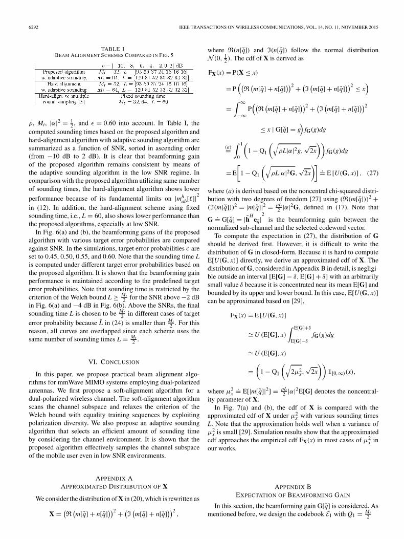
TABLE IBEAM ALIGNMENT SCHEMES COMPARED IN FIG. 5
ρ, Mt, |α|2 = 12 , and ε = 0.60 into account. In Table I, the
computed sounding times based on the proposed algorithm andhard-alignment algorithm with adaptive sounding algorithm aresummarized as a function of SNR, sorted in ascending order(from −10 dB to 2 dB). It is clear that beamforming gainof the proposed algorithm remains consistent by means ofthe adaptive sounding algorithm in the low SNR regime. Incomparison with the proposed algorithm utilizing same numberof sounding times, the hard-alignment algorithm shows lower
performance because of its fundamental limits on |mhab[�]|
2
in (12). In addition, the hard-alignment scheme using fixedsounding time, i.e., L = 60, also shows lower performance thanthe proposed algorithms, especially at low SNR.
In Fig. 6(a) and (b), the beamforming gains of the proposedalgorithm with various target error probabilities are comparedagainst SNR. In the simulations, target error probabilities ε areset to 0.45, 0.50, 0.55, and 0.60. Note that the sounding time Lis computed under different target error probabilities based onthe proposed algorithm. It is shown that the beamforming gainperformance is maintained according to the predefined targeterror probabilities. Note that sounding time is restricted by thecriterion of the Welch bound L ≥ Mt
2 for the SNR above −2 dBin Fig. 6(a) and −4 dB in Fig. 6(b). Above the SNRs, the finalsounding time L is chosen to be Mt
2 in different cases of targeterror probability because L in (24) is smaller than Mt
2 . For thisreason, all curves are overlapped since each scheme uses thesame number of sounding times L = Mt
2 .
VI. CONCLUSION
In this paper, we propose practical beam alignment algo-rithms for mmWave MIMO systems employing dual-polarizedantennas. We first propose a soft-alignment algorithm for adual-polarized wireless channel. The soft-alignment algorithmscans the channel subspace and relaxes the criterion of theWelch bound with equality training sequences by exploitingpolarization diversity. We also propose an adaptive soundingalgorithm that selects an efficient amount of sounding timeby considering the channel environment. It is shown that theproposed algorithm effectively samples the channel subspaceof the mobile user even in low SNR environments.
APPENDIX AAPPROXIMATED DISTRIBUTION OF X
We consider the distribution of X in (20), which is rewritten as
X = (R(m[q] + n[q]))2 + (
I(m[q] + n[q]))2 ,
where R(n[q]) and I(n[q]) follow the normal distributionN (0, 1
2 ). The cdf of X is derived as
FX(x) = P(X ≤ x)
= P((R(m[q] + n[q]))2 + (
I(m[q] + n[q]))2 ≤ x
)
=∫ ∞
−∞P((R(m[q] + n[q]))2 + (
I(m[q] + n[q]))2
≤ x | G[q] = g)
fG(g)dg
(a)=∫ 1
0
(1 − Q1
(√ρL|α|2g,
√2x
))fG(g)dg
= E
[1 − Q1
(√ρL|α|2G,
√2x
)].= E [U(G, x)] , (27)
where (a) is derived based on the noncentral chi-squared distri-bution with two degrees of freedom [27] using (R(m[q]))2 +(I(m[q]))2 = |m[q]|2 = ρL
2 |α|2G, defined in (17). Note that
G .= G[q] = |hHeq|
2is the beamforming gain between the
normalized sub-channel and the selected codeword vector.To compute the expectation in (27), the distribution of G
should be derived first. However, it is difficult to write thedistribution of G in closed-form. Because it is hard to computeE[U(G, x)] directly, we derive an approximated cdf of X. Thedistribution of G, considered in Appendix B in detail, is negligi-ble outside an interval [E[G] − δ, E[G] + δ] with an arbitrarilysmall value δ because it is concentrated near its mean E[G] andbounded by its upper and lower bound. In this case, E[U(G, x)]can be approximated based on [29],
FX(x) = E [U(G, x)]
U (E[G], x)∫ E[G]+δ
E[G]−δ
fG(g)dg
U (E[G], x)
=(
1 − Q1
(√2μ2
x,√
2x
))1[0,∞)(x),
where μ2x
.= E[|m[q]|2] = ρL2 |α|2E[G] denotes the noncentral-
ity parameter of X.In Fig. 7(a) and (b), the cdf of X is compared with the
approximated cdf of X under μ2x with various sounding times
L. Note that the approximation holds well when a variance ofμ2
x is small [29]. Simulation results show that the approximatedcdf approaches the empirical cdf FX(x) in most cases of μ2
x inour works.
APPENDIX BEXPECTATION OF BEAMFORMING GAIN
In this section, the beamforming gain G[q] is considered. Asmentioned before, we design the codebook E1 with Q1 = Mt
2

SONG et al.: ADAPTIVE MILLIMETER WAVE BEAM ALIGNMENT FOR DUAL-POLARIZED MIMO SYSTEMS 6293
Fig. 6. Beamforming gain of proposed algorithm against SNR with different target error probabilities (Mt = 32, 64, Mr = 2, χ = 0.2). (a) Mt = 32, Mr = 2.(b) Mt = 64, Mr = 2.
Fig. 7. Distribution analysis of X (μ2x = ρL
2 |α|2E[G[q]], ρ = −10 dB). (a) Mt = 32. (b) Mt = 64.
codewords based on [5], [6]. In the codebook, when Q1 = Mt2 ,
each codeword is represented by the normalized array response
vector√
2Mt
a Mt2
(θ) in (6). Thus, the beamforming gain G[q]in (23) between the normalized sub-channel h and the q-thcodeword eq = 1√
NaN(θq) with N elements is given by [30]
G[q]=∣∣aH
N (θq + φq)aN(θq)∣∣2
N2 = 1
N2
sin2(
πηN2
)sin2 (πη
2
) .=� (|η|) (28)
where θq is the AoD beam direction of the q-th codeword, φqis the beam direction difference between the q-th codewordand the sub-channel vector and η
.= sin θq − sin(θq + φq) is thebeam direction difference in the ψ-domain in Fig. 8. G[q] isbounded by its upper and lower bound, i.e., 1 and τ 2.
Fig. 8. Quantized sector for each codeword.
In the codebook of [5], [6], the beam-width of each codewordis considered in the ψ-domain. To optimize the codebook,the beam-widths of each codeword is equally divided in the
6294 IEEE TRANSACTIONS ON WIRELESS COMMUNICATIONS, VOL. 14, NO. 11, NOVEMBER 2015
ψ-domain as 2T.= sin θUB−sin θLB
Q where θUB and θLB are theupper and lower bounds of the entire range, respectively. Then,the upper beam-width �u,q and the lower beam-width �l,q ofeach codeword is given by
sin(θq + �u,q) − sin θq = T, (29)
sin θq − sin(θq + �l,q) = T. (30)
In the q-th quantized sector, �u,q and �l,q are dependent onthe beam direction θq of the codeword eq. In order to computethe expected value of the beamforming gain, the beam-widthof each sector needs to be represented by the beam directionθq. The beam-width of each codeword in the θ -domain isapproximated in the following lemma.
Lemma 1: The upper and lower beam-widths of each code-word may be approximated as
�θq
.= �u,q = �l,q T
cos θq,
when the beam-width is sufficiently small.Proof: First, we consider the upper beam-width of q-th
sector with eq. The upper beam-width �u,q is derived as
T = sin θq cos(�u,q) + cos θq sin(�u,q) − sin θq
sin θq
(1 − �2
u,q
2
)+ cos θq�u,q − sin θq
cos θq�u,q.
The first approximation is based on the small-angle approx-imation of trigonometric functions, i.e., sin � �, cos � 1 − �2
2 , since the half beam-width �u,q is designed to have a
sufficiently small value. Then, we drop the�2
u,q2 term since �2
u,qapproaches 0.
The lower beam-width in (30) is approximated in the sameway and has an identical value. The upper and lower beam-widths of the q-th sector in the θ -domain is approximated as
�θq.= �u,q = �l,q T
cos θq.
The upper and lower beam-width are functions of the beamdirection θq and the half beam-width T in the ψ-domain. �
With the approximate beam-width in Lemma 1, the expec-tation of beamforming gain E[�(|η|)] is upper bounded. Thebeamforming gain is defined with two random variables, θq andφq in (28). Because it is hard to derive E[�(|η|)] directly, wederive an upper bound of E[�(|η|)].
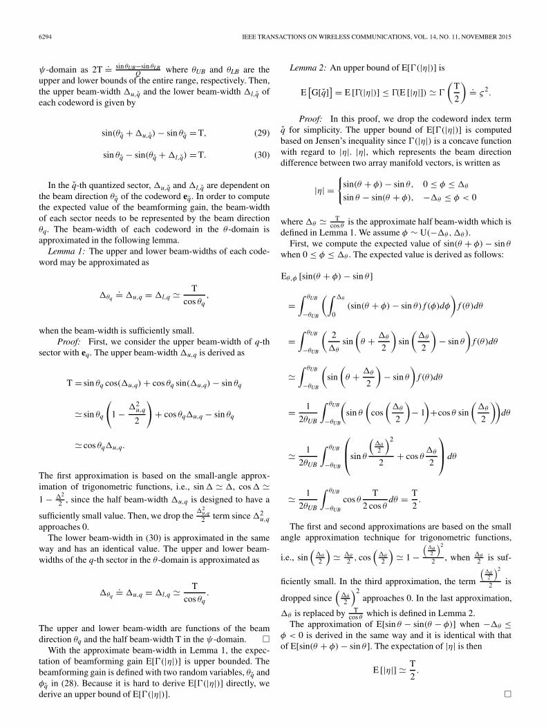
Lemma 2: An upper bound of E[�(|η|)] is
E[G[q]] = E [�(|η|)] ≤ �(E [|η|]) �
(T
2
).= ς2.
Proof: In this proof, we drop the codeword index termq for simplicity. The upper bound of E[�(|η|)] is computedbased on Jensen’s inequality since �(|η|) is a concave functionwith regard to |η|. |η|, which represents the beam directiondifference between two array manifold vectors, is written as
|η| ={
sin(θ + φ) − sin θ, 0 ≤ φ ≤ �θ
sin θ − sin(θ + φ), −�θ ≤ φ < 0
where �θ Tcos θ
is the approximate half beam-width which isdefined in Lemma 1. We assume φ ∼ U(−�θ,�θ).
First, we compute the expected value of sin(θ + φ) − sin θ
when 0 ≤ φ ≤ �θ . The expected value is derived as follows:
Eθ,φ [sin(θ + φ) − sin θ ]
=∫ θUB
−θUB
(∫ �θ
0(sin(θ + φ) − sin θ) f (φ)dφ
)f (θ)dθ
=∫ θUB
−θUB
(2
�θ
sin
(θ + �θ
2
)sin
(�θ
2
)− sin θ
)f (θ)dθ
∫ θUB
−θUB
(sin
(θ + �θ
2
)− sin θ
)f (θ)dθ
= 1
2θUB
∫ θUB
−θUB
(sin θ
(cos
(�θ
2
)− 1
)+cos θ sin
(�θ
2
))dθ
1
2θUB
∫ θUB
−θUB
⎛⎜⎝sin θ
(�θ
2
)2
2+ cos θ
�θ
2
⎞⎟⎠ dθ
1
2θUB
∫ θUB
−θUB
cos θT
2 cos θdθ = T
2.
The first and second approximations are based on the smallangle approximation technique for trigonometric functions,
i.e., sin(
�θ
2
) �θ
2 , cos(
�θ
2
) 1 −
(�θ2
)2
2 , when �θ
2 is suf-
ficiently small. In the third approximation, the term
(�θ2
)2
2 is
dropped since(
�θ
2
)2approaches 0. In the last approximation,
�θ is replaced by Tcos θ
which is defined in Lemma 2.The approximation of E[sin θ − sin(θ − φ)] when −�θ ≤
φ < 0 is derived in the same way and it is identical with thatof E[sin(θ + φ) − sin θ ]. The expectation of |η| is then
E [|η|] T
2.
�

SONG et al.: ADAPTIVE MILLIMETER WAVE BEAM ALIGNMENT FOR DUAL-POLARIZED MIMO SYSTEMS 6295
Fig. 9. Beamforming gain analysis of codebook [5], [6]. (a) N = 16, θUB = −θLB = π3 . (b) N = 32, θUB = −θLB = π
3 . (c) N = 16, Q = 32, θUB = −θLB.(d) N = 32, Q = 64, θUB = −θLB.
In Fig. 9, the approximate upper bound of E[�(|η|)] is com-pared with the simulation results with the codebook. In Fig. 9(a)and (b), the beamforming gain of the codebook is comparedagainst the number of codewords under R θUB = −θLB = π
3 .In Fig. 9(c) and (d), the beamforming gain of the codebookis compared against the bounds of possible AoDs. Note thatthe simulation results for E[�(|η|)] are upper bounded by theformulation ς2 in Lemma 2.
REFERENCES
[1] A. Ghosh et al., “Millimeter wave enhanced local area systems: A highdata rate approach for future wireless networks,” IEEE J. Sel. AreasCommun., vol. 32, no. 6, pp. 1152–1163, Jun. 2014.
[2] Z. Pi and F. Khan, “An introduction to millimeter-wave mobile broadbandsystems,” IEEE Commun. Mag., vol. 49, no. 6, pp. 101–107, Jun. 2011.
[3] T. S. Rappaport et al., “Millimeter wave mobile communications for 5Gcellular: It will work!” IEEE Access, vol. 1, pp. 335–349, May 2013.
[4] W. Roh et al., “Millimeter-wave beamforming as an enabling technologyfor 5G cellular communications: Theoretical feasibility and prototyperesults,” IEEE Commun. Mag., vol. 52, no. 2, pp. 106–113, Feb. 2014.
[5] S. Hur et al., “Millimeter wave beamforming for wireless backhaul andaccess in small cell networks,” IEEE Trans. Commun., vol. 61, no. 10,pp. 4391–4403, Oct. 2013.
[6] S. Hur et al., “Multilevel millimeter wave beamforming for wireless back-haul,” in Proc. IEEE Global Telecommun. Conf. Workshops, Dec. 2011,pp. 253–257.
[7] PHY/MAC complete proposal specification (TGad D0.1), IEEE Std.802.11-10/0433r2, 2012.
[8] J. Song, S. G. Larew, D. J. Love, T. A. Thomas, and A. Ghosh, “Millimeterwave beam-alignment for dual-polarized outdoor MIMO systems,” in Proc.IEEE Global Telecommun. Conf. Workshops, Dec. 2013, pp. 356–361.
[9] J. Song, S. G. Larew, D. J. Love, T. A. Thomas, and A. Ghosh, “Millimeterwave beamforming for multiuser dual-polarized MIMO systems,” in Proc.IEEE Global Conf. Signal Inf. Process., Dec. 2013, pp. 719–722.
[10] C. Oestges, V. Erceg, and A. H. Paulraj, “Propagation modeling of MIMOmultipolarized fixed wireless channels,” IEEE Trans. Veh. Technol.,vol. 53, no. 3, pp. 644–654, May 2004.
[11] H. Asplund, J. Berg, F. Harrysson, J. Medho, and M. Riback, “Propagationcharacteristics of polarized radio waves in cellular communications,” inProc. IEEE Veh. Technol. Conf., Sep./Oct. 2007, pp. 839–843.
[12] L. Jiang, L. Thiele, and V. Jungnickel, “On the modelling of polarizedMIMO channel,” in Proc. Eur. Wireless Conf., Apr. 2007, pp. 440–444.
[13] M. Coldrey, “Modeling and capacity of polarized MIMO channels,” inProc. IEEE Veh. Technol. Conf., May 2008, pp. 440–444.
[14] T. Kim, B. Clerckx, D. J. Love, and S. J. Kim, “Limited feedback beam-forming systems in dual-polarized MIMO channel,” IEEE Trans. WirelessCommun., vol. 9, no. 11, pp. 3425–3439, Nov. 2010.
[15] J. Choi, B. Clerckx, and D. J. Love, “Differential codebook for general ro-tated dual-polarized MISO channels,” in Proc. IEEE Global Telecommun.Conf., Dec. 2012, pp. 4222–4227.
[16] Y. H. Nam et al., “Evolution of reference signals for LTE-Advancedsystems,” IEEE Commun. Mag., vol. 50, no. 2, pp. 132–138, Feb. 2012.
[17] S. Sesia, I. Toufik, and M. Baker, LTE, the UMTS Long Term Evolution,2nd ed. Chichester, U.K.: Wiley, 2011.
[18] Physical channels and modulation, 3GPP TS 36.211 v10.1.0 Std.,3rd Generation Partnership Project, Sophia Antipolis Cedex, France,Mar. 2011.
[19] T. A. Thomas, H. C. Nguyen, G. R. MacCartney, and T. S. Rappaport, “3DmmWave channel model proposal,” in Proc. IEEE Veh. Technol. Conf.,Sep. 2014, pp. 1–6.
[20] H. Zhang, S. Venkateswaran, and U. Madhow, “Channel modeling andMIMO capacity for outdoor millimeter wave links,” in Proc. IEEEWireless Commun. Netw. Conf., Apr. 2010, pp. 1–6.
[21] T. S. Rappaport, E. Ben-Dor, J. N. Murdock, and Y. Qiao, “38 GHzand 60 GHz angle-dependent propagation for cellular & peer-to-peerwireless communications,” in Proc. IEEE Int. Conf. Commun., Jun. 2012,pp. 4568–4573.

6296 IEEE TRANSACTIONS ON WIRELESS COMMUNICATIONS, VOL. 14, NO. 11, NOVEMBER 2015
[22] A. Sayeed and J. Brady, “Beamspace MIMO for high-dimensional mul-tiuser communication at millimeter-wave frequencies,” in Proc. IEEEGlobal Telecommun. Conf., Dec. 2013, pp. 3679–3684.
[23] Z. Muhi-Eldeen, L. Ivrissimtzis, and M. Al-Nuaimi, “Modelling and mea-surements of millimeter wavelength propagation in urban environments,”IET Microw. Antennas Propag., vol. 4, no. 9, pp. 1300–1309, Sep. 2010.
[24] D. J. Love and R. W. Heath, “Equal gain transmission in multiple-inputmultiple-output wireless systems,” IEEE Trans. Commun., vol. 51, no. 7,pp. 1102–1110, Jul. 2003.
[25] W. Santipach and M. L. Honig, “Optimization of training and feedbackoverhead for beamforming over block fading channels,” IEEE Trans. Inf.Theory, vol. 56, no. 12, pp. 6103–6115, Dec. 2010.
[26] R. Remmert, Theory of Complex Functions. New York, NY, USA:Springer-Verlag, 1991.
[27] J. G. Proakis, Digital Communications, 4th ed. New York, NY, USA:McGraw-Hill, 2001.
[28] G. Calcev et al., “A wideband spatial channel model for system-wide simu-lations,” IEEE Trans. Veh. Technol., vol. 56, no. 2, pp. 389–403, Mar. 2007.
[29] A. Papoulis and S. U. Pillai, Probability, Random Variables and StochasticProcesses, 4th ed. New York, NY, USA: McGraw-Hill, 2002.
[30] R. C. Hansen, Phased Array Antennas, 2nd ed. Hoboken, NJ, USA:Wiley, 2009.
Jiho Song (S’15) received the B.S. and M.S. degreesin electrical engineering from Seoul National Uni-versity, Seoul, Korea, in 2009 and 2011, respectively.He is currently working toward the Ph.D. degreewith Purdue University, West Lafayette, IN, USA.His current research interests are in the design andanalysis of millimeter wave communication, mul-tiuser MIMO communication, multicell cooperativetransmission, adaptive communication, and limitedfeedback strategies for massive MIMO systems.
Junil Choi (S’12–M’15) received the B.S. (withhonors) and M.S. degrees in electrical engineeringfrom Seoul National University, Seoul, Korea, in2005 and 2007, respectively, and the Ph.D. degreein electrical and computer engineering from PurdueUniversity, West Lafayette, IN, USA, in 2015. He iscurrently a Post-Doctorate Fellow at The Universityof Texas at Austin, Austin, TX, USA. From 2007to 2011, he was a member of the technical staff atSamsung Advanced Institute of Technology (SAIT)and Samsung Electronics Co. Ltd. in Korea, where
he contributed to advanced codebook and feedback framework designs to the3GPP LTE/LTE-Advanced and IEEE 802.16m standards. His research interestsare in the design and analysis of massive MIMO, distributed communication,and vehicular communication systems.
Stephen G. Larew (S’14) received the B.S. degree(with distinction) in electrical engineering in 2012from Purdue University, West Lafayette, IN, USA,where he is currently working toward the Ph.D.degree. During the summers of 2013 and 2015, hewas an Intern at Nokia Networks and Raytheon BBNTechnologies, respectively. His current research in-terests are in the design of adaptive multiple an-tenna wireless systems and software defined radio.He is an active member of Eta Kappa Nu.
David J. Love (S’98–M’05–SM’09–F’15) receivedthe B.S. (with highest honors), M.S.E., and Ph.D.degrees from The University of Texas at Austin,Austin, TX, USA, in 2000, 2002, and 2004, re-spectively, all in electrical engineering. During thesummers of 2000 and 2002, he was with TexasInstruments, Dallas, TX. Since August 2004, he hasbeen with the School of Electrical and ComputerEngineering, Purdue University, West Lafayette, IN,USA, where he is currently a Professor and rec-ognized as a University Faculty Scholar. He is the
holder of 23 issued U.S. patents.Dr. Love is a Fellow of the Royal Statistical Society. He has served as
an Editor of the IEEE TRANSACTIONS ON COMMUNICATIONS, an Asso-ciate Editor of the IEEE TRANSACTIONS ON SIGNAL PROCESSING, and aGuest Editor of special issues of the IEEE JOURNAL ON SELECTED AREAS IN
COMMUNICATIONS and the EURASIP Journal on Wireless Communicationsand Networking. He was a corecipient of the 2009 IEEE Transactions onVehicular Technology Jack Neubauer Memorial Award for the best systemspaper published in the IEEE TRANSACTIONS ON VEHICULAR TECHNOLOGY
and multiple Globecom best paper awards. He was the recipient of the Fall 2010Purdue HKN Outstanding Teacher Award, the Fall 2013 Purdue ECE GraduateStudent Association Outstanding Faculty Award, and the Spring 2015 PurdueHKN Outstanding Professor Award. He has been also inducted into Tau BetaPi and Eta Kappa Nu. He is recognized as a Thomson Reuters Highly CitedResearcher.
Timothy A. Thomas (S’95–M’98) received the B.S.degree from the University of Illinois at Urbana-Champaign, Urbana, IL, USA, in 1989, the M.S.degree from the University of Michigan, Ann Arbor,MI, USA, in 1990, and the Ph.D. degree from PurdueUniversity, West Lafayette, IN, USA, in 1997, all inelectrical engineering. From 1991 to 1993, he wasa member of the technical staff at Bell Communi-cations Research (Bellcore), Red Bank, NJ, USA,and from 1997 to 2011, he was with Motorola,Schaumburg, IL, USA, working on wireless re-
search. Since 2011, he has been with Nokia Networks (formally NSN),Arlington Heights, IL, working in the research group within technology andinnovation. His research interests are in physical layer communications and, inparticular, channel measurements, cellular and mmWave communications, andadaptive antenna algorithms for mobile broadband communications.
Amitabha (Amitava) Ghosh (M’86–SM’06–F’15)received the Ph.D. degree in electrical engineeringfrom Southern Methodist University, Dallas, TX,USA. After receiving the Ph.D. degree, in 1990,he joined Motorola, where he worked on multiplewireless technologies, including IS-95, cdma-2000,1xEV-DV/1XTREME, 1xEV-DO, UMTS, HSPA,802.16e/WiMAX/802.16m, Enhanced EDGE, and3GPP LTE. He is currently the Head of the NorthAmerica Radio Systems Research within the Tech-nology and Innovation office of Nokia Networks,
Arlington Heights, IL, USA. He is currently working on 3GPP LTE-Advancedand 5G technologies. He has authored or coauthored numerous external andinternal technical papers. He is the co-author of Essentials of LTE and LTE-A.He is the holder of 60 issued patents. His research interests are in the areasof digital communications, signal processing, and wireless communications.Dr. Ghosh is a Fellow of IEEE.