Adaptive Frequency Hopped Alamouti-Coded OFDM …home.iitk.ac.in/~javeda/MTech_ppt.pdf · Adaptive...
53
Introduction Frequency Hopping Channel Estimation Alamouti-Coded OFDM Conclusions and Future Work Adaptive Frequency Hopped Alamouti-Coded OFDM System Javed Akhtar Thesis Supervisor-Dr. Govind Sharma Department of Electrical Engineering Indian Institute of Technology Kanpur July 2013
Transcript of Adaptive Frequency Hopped Alamouti-Coded OFDM …home.iitk.ac.in/~javeda/MTech_ppt.pdf · Adaptive...

Introduction Frequency Hopping Channel Estimation Alamouti-Coded OFDM Conclusions and Future Work
Adaptive Frequency Hopped Alamouti-CodedOFDM System
Javed AkhtarThesis Supervisor-Dr. Govind Sharma
Department of Electrical EngineeringIndian Institute of Technology Kanpur
July 2013

Introduction Frequency Hopping Channel Estimation Alamouti-Coded OFDM Conclusions and Future Work
Outline1 Introduction
DiversityOFDMSystem Model
2 Frequency HoppingUniform Frequency HoppingNon-Uniform Frequency HoppingAdaptive Frequency Hopping
3 Channel EstimationPilot ArrangementChannel InterpolationChannel Estimation Techniques
4 Alamouti-Coded OFDMAlamouti SchemeAlamouti Coded OFDM System
5 Conclusions and Future Work
Introduction Frequency Hopping Channel Estimation Alamouti-Coded OFDM Conclusions and Future Work
In modern wireless communications, power and bandwidthare two of the most important resources
Recent demand is for high data rate and to support morenumber of users
In real scenario, the performance may degrade because offading nature of the Rayleigh multipath channel
For a power and bandwidth limited system, diversity canbe used to enhance the system performance

Introduction Frequency Hopping Channel Estimation Alamouti-Coded OFDM Conclusions and Future Work
Diversity
Diversity
Diversity order measures the number of availableindependent copies of the same signalThe diversity gain is achieved using one of the followingdiversity scheme:
Frequency DiversityTime DiversitySpace Diversity
Transmit diversity is a class of Space diversity, wheremultiple antennas are used at the transmitter

Introduction Frequency Hopping Channel Estimation Alamouti-Coded OFDM Conclusions and Future Work
OFDM
OFDM
Multichannel transmission scheme through which veryhigh data transmission rate can be achieved
Transmitting sub-carriers used are orthogonal to eachother
Sub-carriers of an OFDM can be represented as
{e j2πfk t}N−1k=0
fk =k
Tsymwhere, 0 ≤ t ≤ Tsym
OFDM decomposes a wideband frequency-selectivechannel into several parallel narrowband frequencyflat-fading channels

Introduction Frequency Hopping Channel Estimation Alamouti-Coded OFDM Conclusions and Future Work
OFDM
Thus, avoids the problem of inter-symbol interference (ISI)in frequency selective channels
The discrete-time baseband model of an OFDM signal canbe represented by:
y [m] =L−1∑l=0
hlx [m − l ] + w [m] (1)
Where, L is the number of taps of the Rayleigh channelmodel, w is the AWGN (Additive White Gaussian Noise)and hl is the lth tap of the Rayleigh channel. The channelh is normally distributed h ∼ N(0, 1)
Introduction Frequency Hopping Channel Estimation Alamouti-Coded OFDM Conclusions and Future Work
System Model
System Model
16-QAM/BPSK
ADAPTIVE
HOPPING
STBCENCODER
IFFT
IFFT
FFT
ChannelEstimation
Space-TimeDECODER
DEHOPPING MAPPING
FEEDBACK
h
h
0
1
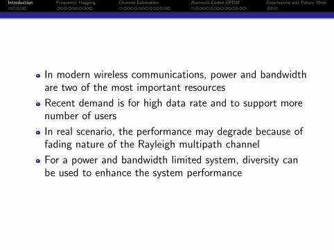
Figure: AFH Alamouti-Coded OFDM System

Introduction Frequency Hopping Channel Estimation Alamouti-Coded OFDM Conclusions and Future Work
System Model
Modulation Mode BPSK 16QAM
Number of Bits per Symbol 1 4FFT Points 64 128
Number of Sub-carriers 64 128Length of CP 16 16
Number of Data Sub-carriers 52 112Channel Model AWGN and Rayleigh AWGN and RayleighChannel Taps 10 10
Table: Simulation Parameters
Assumptions:
Single User transmission caseChannel State Information (CSI) known at the receiverSlow fading channelSome feedback mechanism exist between receiver and transmitter

Introduction Frequency Hopping Channel Estimation Alamouti-Coded OFDM Conclusions and Future Work
Frequency Hopping
Exploits the frequency diversity
Provides low probability of interception
Hopping pattern generated is random
Types of Frequency Hopping
RF-Carrier Frequency HoppingSub-carrier Hopping

Introduction Frequency Hopping Channel Estimation Alamouti-Coded OFDM Conclusions and Future Work
Types of Sub-carrier Hopping
Uniform Frequency Hopping
Non-Uniform Frequency Hopping
Adaptive Frequency Hopping

Introduction Frequency Hopping Channel Estimation Alamouti-Coded OFDM Conclusions and Future Work
Uniform Frequency Hopping
Uniform Frequency Hopping
For each OFDM symbols, equal translation of all the sub-carriersacross the band is provided
sub-band 1 sub-band 2 sub-band Q. . .f
1 2 k K
W
Figure: Uniform Sub-carrier Hopping
Bandwidth W is partitioned into number of sub-bands, indexed fromq = 1, 2, · · · ,Qf and each of the sub-bands has K sub-carriers
Where, Qc = K .Qf is the total number of sub-carriers
A single user can select any K number of sub-carriers from the Qc
available sub-carriers
* M. Jiang and L. Hanzo, ”Multiuser mimo-ofdm systems using subcarrierhopping,” Communications, IEE Proceedings-, vol. 153, no. 6, pp. 802-809, 2006

Introduction Frequency Hopping Channel Estimation Alamouti-Coded OFDM Conclusions and Future Work
Uniform Frequency Hopping
Result for Uniform Frequency Hopping for BPSK OFDM
0 5 10 15 20 2510
−5
10−4
10−3
10−2
10−1
100
Eb/No in dB
BE
R
BER for BPSK Uniform FH−OFDM in 10−tap Rayleigh channel
Rayleigh−Theory
Sim.(FH OFDM)

Introduction Frequency Hopping Channel Estimation Alamouti-Coded OFDM Conclusions and Future Work
Uniform Frequency Hopping
Result for Uniform Frequency Hopping for 16-QAM OFDM
0 5 10 15 20 2510
−4
10−3
10−2
10−1
100
Eb/No in dB
BE
R
BER for 16−qam Uniform FH−OFDM in 10 tap Rayleigh channel
Rayleigh−TheorySim−(Uniform FH OFDM)Sim−(OFDM)

Introduction Frequency Hopping Channel Estimation Alamouti-Coded OFDM Conclusions and Future Work
Non-Uniform Frequency Hopping
Non-Uniform Frequency Hopping
For each OFDM symbols, different translation for each of thesub-carriers of the same user across the band is provided
Figure: Non-Uniform Sub-carrier Hopping
User can use any of the K among the Qc available sub-carriers
Sub-carriers occupied by a user may not be adjacent to each other
Advantage of this hopping pattern is that it reduces the ICI(Inter-Carrier Interference)
* M. Jiang and L. Hanzo ,”Multiuser mimo-ofdm systems using subcarrierhopping,” Communications, IEE Proceedings-, vol. 153, no. 6, pp. 802-809, 2006
Introduction Frequency Hopping Channel Estimation Alamouti-Coded OFDM Conclusions and Future Work
Non-Uniform Frequency Hopping
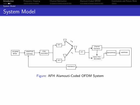
Result for Non-Uniform Frequency Hopping for BPSKOFDM
0 5 10 15 20 2510
−5
10−4
10−3
10−2
10−1
100
Eb/No in dB
BE
R
BER for BPSK Non−Uniform FH−OFDM in 10−tap Rayleigh channel
Rayleigh−Theory
Sim−(Non−Uniform FH OFDM)

Introduction Frequency Hopping Channel Estimation Alamouti-Coded OFDM Conclusions and Future Work
Non-Uniform Frequency Hopping
Result for Non-Uniform Frequency Hopping for 16-QAMOFDM
0 5 10 15 20 2510
−4
10−3
10−2
10−1
100
Eb/No in dB
BE
R
BER for 16−qam Non−Uniform FH−OFDM in 10−tap Rayleigh channel
Rayleigh−TheorySim−(Non−Uniform FH OFDM)Sim−(OFDM)

Introduction Frequency Hopping Channel Estimation Alamouti-Coded OFDM Conclusions and Future Work
Adaptive Frequency Hopping
Adaptive Frequency Hopping
Hopping pattern is decided based on the channelconditions
LQA (Link Quality Analyser)** is used at the receiver tofind the SNR (Signal to Noise Ratio) for each sub-carrier
Feedback channel informs about the channel conditionsback to the transmitter
Sub-carriers having the best SNR are selected fortransmission
Channel assumed to remain constant for l (4 to 10)OFDM symbol periods
**F. Wang and X. He,”The Performance Analysis of AFH-OFDM System Basedon Simulink,” in (WiCOM), 2011, 7th International Conference

Introduction Frequency Hopping Channel Estimation Alamouti-Coded OFDM Conclusions and Future Work
Adaptive Frequency Hopping
Result for Adaptive Frequency Hopping for BPSK OFDM
0 5 10 15 20 2510
−5
10−4
10−3
10−2
10−1
100
Eb/No in dB
BE
R
BER for BPSK AFH OFDM in 10−tap Rayleigh channel
Rayleigh−Theory
Sim−(AFH OFDM)Sim−(OFDM)

Introduction Frequency Hopping Channel Estimation Alamouti-Coded OFDM Conclusions and Future Work
Adaptive Frequency Hopping
Result for Adaptive Frequency Hopping for 16-QAMOFDM
0 5 10 15 20 25 3010
−4
10−3
10−2
10−1
100
Eb/No in dB
BE
R
BER for 16QAM AFH OFDM in 10 tap Rayleigh channel
Rayleigh−TheoryAFH OFDM Rayleigh−SimulationOFDM

Introduction Frequency Hopping Channel Estimation Alamouti-Coded OFDM Conclusions and Future Work
Channel Estimation
OFDM symbols get distorted due to channel conditionsand presence of noise
For correct detection of data, channel should be estimatedand compensated
Channel estimation is done using pilot-symbols
Channel across each sub-carrier can be independentlyestimated for OFDM symbols

Introduction Frequency Hopping Channel Estimation Alamouti-Coded OFDM Conclusions and Future Work
Pilot Arrangement
Pilot Arrangement
Pilot-aided estimation can be of three types
Block-Type Pilot Arrangement
Comb-Type Pilot Arrangement
Lattice-Type Pilot Arrangement

Introduction Frequency Hopping Channel Estimation Alamouti-Coded OFDM Conclusions and Future Work
Pilot Arrangement
Block-Type
Pilots at all sub-carriers are transmitted periodically
To mitigate the effects of time-varying channel, pilotsymbols should be placed in respect to the coherence time
This type of pilot-arrangement is applicable forslow-varying channels
Each channel can be estimated independently as they areorthogonal (free from ISI) to each other
The pilot symbol period must satisfy the inequality:
St ≤1
fD
Where, St is the pilot symbol period

Introduction Frequency Hopping Channel Estimation Alamouti-Coded OFDM Conclusions and Future Work
Pilot Arrangement
Pilot arrangement for a Block-type*
Time
StOFDM Symbols
Where, fD is the doppler frequency given by:
fD =v
c∗ fc ∗ cos θ
*S. Coleri, M. Ergen, A. Puri, and A. Bahai,”Channel estimation techniques basedon pilot arrangement in ofdm systems,” Broadcasting, IEEE Transactions on, vol. 48,no. 3, pp. 223-229, 2002
Introduction Frequency Hopping Channel Estimation Alamouti-Coded OFDM Conclusions and Future Work
Pilot Arrangement
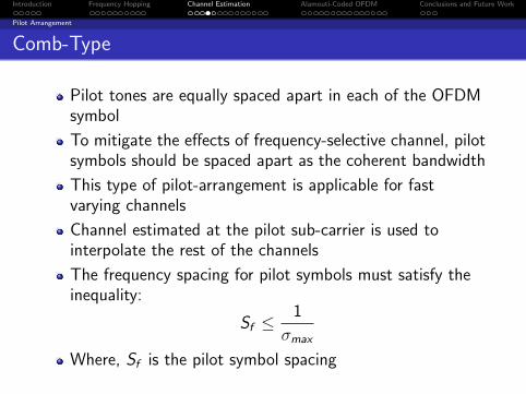
Comb-Type
Pilot tones are equally spaced apart in each of the OFDMsymbol
To mitigate the effects of frequency-selective channel, pilotsymbols should be spaced apart as the coherent bandwidth
This type of pilot-arrangement is applicable for fastvarying channels
Channel estimated at the pilot sub-carrier is used tointerpolate the rest of the channels
The frequency spacing for pilot symbols must satisfy theinequality:
Sf ≤1
σmax
Where, Sf is the pilot symbol spacing

Introduction Frequency Hopping Channel Estimation Alamouti-Coded OFDM Conclusions and Future Work
Pilot Arrangement
Pilot arrangement for a Comb-type*
Time
Sf
OFDM Symbol
Where, σmax is the maximum delay spread, incurred due to multipath
*S. Coleri, M. Ergen, A. Puri, and A. Bahai,”Channel estimation techniques basedon pilot arrangement in ofdm systems,” Broadcasting, IEEE Transactions on, vol. 48,no. 3, pp. 223-229, 2002

Introduction Frequency Hopping Channel Estimation Alamouti-Coded OFDM Conclusions and Future Work
Channel Interpolation
Channel Interpolation
Channel information at pilot sub-carriers are used toestimate channels at data sub-carriers throughinterpolation
Channel estimation using linear interpolation atdata-carrier k , mL < k < (m + 1)L, is given by:
He(k) = He(mL + l); 0 ≤ l < L
= (Hp(m + 1)− Hp(m))l
L+ Hp(m) (2)

Introduction Frequency Hopping Channel Estimation Alamouti-Coded OFDM Conclusions and Future Work
Channel Interpolation
Estimate of channel using second order interpolation isgiven by:
He(k) = He(mL + l)
= c1Hp(m − 1) + c0Hp(m) + c−1Hp(m − 1) (3)
Where, c1 = α(α−1)2
c0 = −(α− 1)(α + 1); α = lN
c−1 = α(α+1)2
Introduction Frequency Hopping Channel Estimation Alamouti-Coded OFDM Conclusions and Future Work
Channel Interpolation
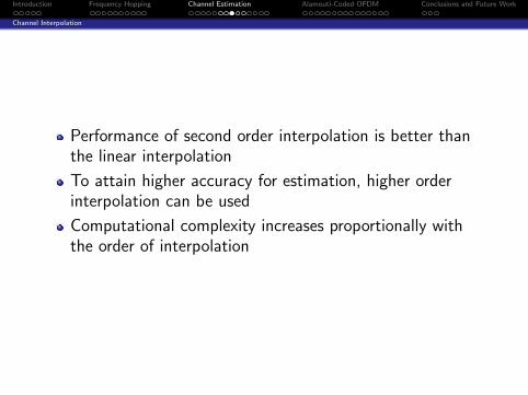
Performance of second order interpolation is better thanthe linear interpolation
To attain higher accuracy for estimation, higher orderinterpolation can be used
Computational complexity increases proportionally withthe order of interpolation

Introduction Frequency Hopping Channel Estimation Alamouti-Coded OFDM Conclusions and Future Work
Channel Interpolation
Lattice-Type
Pilot tones are spaced apart equally along the frequencyand time axis
Pilot tones spaced in both frequency and time axis areused for interpolation and for channel estimation
To mitigate the effects of frequency-variations andtime-variation of channel, the arrangement of pilotsymbols must satisfy the below inequalities
Sf ≤1
σmax
and
St ≤1
fD

Introduction Frequency Hopping Channel Estimation Alamouti-Coded OFDM Conclusions and Future Work
Channel Interpolation
Pilot arrangement for a Lattice-type
Time
Sf
OFDM SymbolS
t
Where, St is the pilot symbol period and Sf is the pilot symbolspacing
Where, σmax is the maximum delay spread, incurred due tomultipath and fD is the doppler frequency

Introduction Frequency Hopping Channel Estimation Alamouti-Coded OFDM Conclusions and Future Work
Channel Estimation Techniques
Channel Estimation Techniques
Channel estimation based on training symbols providesgood performance
Efficiency of transmission decreases because of theaddition of overhead training symbolsTechniques used for channel estimation are:
LS (Least Square)MMSE (Minimum Mean Square Error)

Introduction Frequency Hopping Channel Estimation Alamouti-Coded OFDM Conclusions and Future Work
Channel Estimation Techniques
The diagonal matrix for N sub-carriers for the trainingsymbols can be represented as:
X =
X [0] 0 · · · 0
0 X [1] · · · 0...
. . . 00 · · · 0 X [N − 1]
Where X [K ] represents the pilot tone present at the K thsub-carrierFor each sub-carrier k , the received training signal can berepresented as
Y [k] = H[k]X [k] + z [k]; K = 0, 1, · · · ,N − 1
H(k) is the channel vector and Z (k) is the noise vector,with E{Z [K ]} = 0 and Var{Z [K ]} = σ2
z

Introduction Frequency Hopping Channel Estimation Alamouti-Coded OFDM Conclusions and Future Work
Channel Estimation Techniques
LS Channel Estimation
Let channel estimate of H be denoted as H
Least-square estimation is used to minimize below costfunction
J(H) = ||Y − XH ||2
The LS estimate of channel is:
HLS = X−1Y
For ICI-free condition
HLS [k] =Y [k]
X [k]; k = 0, 1, · · · ,N − 1
Introduction Frequency Hopping Channel Estimation Alamouti-Coded OFDM Conclusions and Future Work
Channel Estimation Techniques
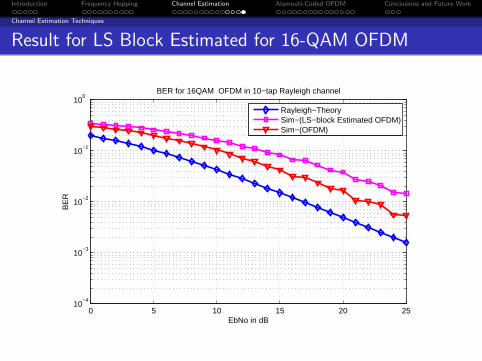
Result for LS Block Estimated for 16-QAM OFDM
0 5 10 15 20 2510
−4
10−3
10−2
10−1
100
EbNo in dB
BE
R
BER for 16QAM OFDM in 10−tap Rayleigh channel
Rayleigh−TheorySim−(LS−block Estimated OFDM)Sim−(OFDM)
Introduction Frequency Hopping Channel Estimation Alamouti-Coded OFDM Conclusions and Future Work
Alamouti is a class of STBC (Space-Time Block Code)
L transmit antennas present at the transmitter can providediversity order of L
Simplest and most elegant scheme for achieving transmitdiversity by utilizing the degree of freedom*
*S. Alamouti,’A simple transmit diversity technique for wireless communications,”Selected Areas in Communications, IEEE Journal on, vol. 16, no. 8, pp. 1451-1458,1998

Introduction Frequency Hopping Channel Estimation Alamouti-Coded OFDM Conclusions and Future Work
Alamouti Scheme
Alamouti Scheme
h
1h
Tx
Tx 1
0
Rx
0
Achieves the same diversity order as MRRC(Maximal-Ratio Receiver Combining) with one transmitantenna and two receive antennas
This scheme can be generalised to two transmit antennaand M receive antennas*
*Z. Jie, L. Liang, and L. Jin,”Performance analysis of space time block code inmimo ofdm systems,” in Communication Software and Networks (ICCSN), 2011 IEEE3rd International Conference on, 2011, pp. 13-16
Introduction Frequency Hopping Channel Estimation Alamouti-Coded OFDM Conclusions and Future Work
Alamouti Scheme
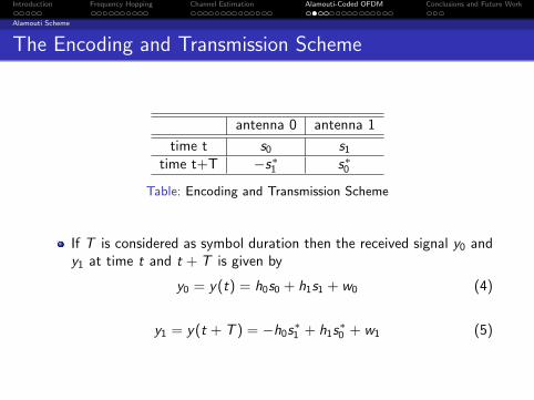
The Encoding and Transmission Scheme
antenna 0 antenna 1
time t s0 s1time t+T −s∗1 s∗0
Table: Encoding and Transmission Scheme
If T is considered as symbol duration then the received signal y0 andy1 at time t and t + T is given by
y0 = y(t) = h0s0 + h1s1 + w0 (4)
y1 = y(t + T ) = −h0s∗1 + h1s∗0 + w1 (5)

Introduction Frequency Hopping Channel Estimation Alamouti-Coded OFDM Conclusions and Future Work
Alamouti Scheme
The above equation can be written as :
[y0 y1
]=[h0 h1
] [ s0 −s∗1s1 s∗0
]+[w0 w1
](6)
Since, we are interested in detecting s0 and s1. So, the aboveequation can be rewritten as:[
y0y∗1
]=
[h0 h1h∗1 −h∗0
] [s0s1
]+
[w0
w∗1
](7)
The square matrix of above equation has it’s columns orthogonal
Hence, the detection problem for s0 and s1 can be decomposed to
s0 = h∗0y0 + h1y∗1 (8)
s1 = h∗1y0 − h0y∗1 (9)

Introduction Frequency Hopping Channel Estimation Alamouti-Coded OFDM Conclusions and Future Work
Alamouti Scheme
Result for Alamouti-Coded BPSK
0 5 10 15 20 2510
−5
10−4
10−3
10−2
10−1
Eb/No in dB
BE
R
BER for BPSK with Alamouti STBC (Rayleigh channel)
theory−Rayleigh (nTx=1,nRx=1)
theory (nTx=2, nRx=1, Alamouti)sim (nTx=2, nRx=1, Alamouti)

Introduction Frequency Hopping Channel Estimation Alamouti-Coded OFDM Conclusions and Future Work
Alamouti Coded OFDM System
Alamouti Coded OFDM System
Figure: Alamouti Coded OFDM system
Data are multiplexed into two streams s0 and s1
Underlying concept of transmission is same as in Alamoutisystem*
*J. Kim, R. Heath, and E. Powers,”Receiver designs for alamouti coded ofdmsystems in fast fading channels,” Wireless Communications, IEEE Transactions on,vol. 4, no. 2, pp. 550-559, 2005

Introduction Frequency Hopping Channel Estimation Alamouti-Coded OFDM Conclusions and Future Work
Alamouti Coded OFDM System
Frequency Domain Analysis
The symbol s0 is given by
s0 = X1(k) = [X1(0),X1(1), · · · ,X1(N − 1)]
and s1 is given by
s1 = X2(k) = [X2(0),X2(1), · · · ,X2(N − 1)]
Let, Y 11 and Y 2
1 represents the output of first antenna attime t and time t + T
Similarly, Y 12 and Y 2
2 represents the output of secondantenna at time t and time t + T

Introduction Frequency Hopping Channel Estimation Alamouti-Coded OFDM Conclusions and Future Work
Alamouti Coded OFDM System
The output from the two antennas at time t can bewritten as:
Y 11 (k) = H1(k)X1(k) + W1(k) ; k = 0, 1, · · · ,N − 1
Y 12 (k) = H2(k)X2(k) + W1(k) ; k = 0, 1, · · · ,N − 1
Similarly, the symbols transmitted at time t + T by thetwo antennas is given by
s3 = −X ∗2 = [−X ∗
2 (0),−X ∗2 (1), · · · ,−X ∗
2 (N − 1)]
and that transmitted by antenna 2 is
s4 = X ∗1 = [X ∗
1 (0),X ∗1 (1), · · · ,X ∗
1 (N − 1)]

Introduction Frequency Hopping Channel Estimation Alamouti-Coded OFDM Conclusions and Future Work
Alamouti Coded OFDM System
The output of the two antennas at time instant t + T canbe written as:
Y 21 (k) = −H1(k)X ∗
2 (k) + W2(k) ; k = 0, 1, · · · ,N − 1
Y 22 (k) = H2(k)X ∗
1 (k) + W2(k) ; k = 0, 1, · · · ,N − 1
Hence, the received symbols Y1 and Y2 is given by thesum of the two transmitted symbols by the two antennasat time t and t + T
Y1(k) = H1(k)X1(k) + H2(k)X2(k) + W1(k)
Y2(k) = −H1(k)X ∗2 (k) + H2(k)X ∗
1 (k) + W2(k)
k = 0, 1, · · · ,N − 1

Introduction Frequency Hopping Channel Estimation Alamouti-Coded OFDM Conclusions and Future Work
Alamouti Coded OFDM System
For decoding purpose we take the conjugate of Y2(k) toget
Y ∗2 (k) = −H∗
1 (k)X2(k) + H∗2 (k)X1(k) + W ∗
2 (k)
k = 0, 1, · · · ,N − 1
Equation for Y1(k) and Y ∗2 (k) can be combined and can
be written as
Y (k) = A(k)X (k) + W (k) (10)
Where,
Y (k) =
[Y1(k)Y ∗2 (k)
], A(k) =
[H1(k) H2(k)H∗
2 (k) −H∗1 (k)
]
Introduction Frequency Hopping Channel Estimation Alamouti-Coded OFDM Conclusions and Future Work
Alamouti Coded OFDM System
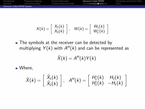
X (k) =
[X1(k)X2(k)
], W (k) =
[W1(k)W ∗
2 (k)
]
The symbols at the receiver can be detected bymultiplying Y (k) with AH(k) and can be represented as
X (k) = AH(k)Y (k)
Where,
X (k) =
[X1(k)
X2(k)
], AH(k) =
[H∗
1 (k) H2(k)H∗
2 (k) −H1(k)
]
Introduction Frequency Hopping Channel Estimation Alamouti-Coded OFDM Conclusions and Future Work
Alamouti Coded OFDM System
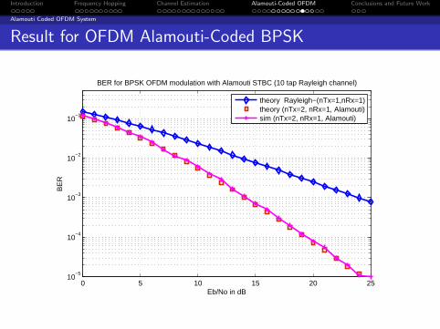
Result for OFDM Alamouti-Coded BPSK
0 5 10 15 20 2510
−5
10−4
10−3
10−2
10−1
Eb/No in dB
BE
R
BER for BPSK OFDM modulation with Alamouti STBC (10 tap Rayleigh channel)
theory Rayleigh−(nTx=1,nRx=1)theory (nTx=2, nRx=1, Alamouti)sim (nTx=2, nRx=1, Alamouti)

Introduction Frequency Hopping Channel Estimation Alamouti-Coded OFDM Conclusions and Future Work
Alamouti Coded OFDM System
Result for OFDM Alamouti-Coded 16-QAM
0 5 10 15 20 2510
−5
10−4
10−3
10−2
10−1
Eb/No in dB
BE
R
BER for 16−QAM OFDM with Alamouti STBC (10 tap Rayleigh channel)
theory (nTx=2, nRx=1, Alamouti)sim (nTx=2, nRx=1, 16QAM OFDM−Alamouti)
Introduction Frequency Hopping Channel Estimation Alamouti-Coded OFDM Conclusions and Future Work
Alamouti Coded OFDM System
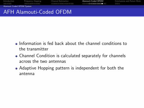
AFH Alamouti-Coded OFDM
Information is fed back about the channel conditions tothe transmitter
Channel Condition is calculated separately for channelsacross the two antennas
Adaptive Hopping pattern is independent for both theantenna

Introduction Frequency Hopping Channel Estimation Alamouti-Coded OFDM Conclusions and Future Work
Result for AFH OFDM Alamouti-Coded BPSK
0 5 10 15 20 2510
−5
10−4
10−3
10−2
10−1
Eb/No in dB
BE
R
BER for BPSK AFH OFDM Alamouti STBC (10 tap Rayleigh channel)
theory (nTx=1, nRx=1)theory (nTx=2, nRx=1, Alamouti)sim (nTx=2, nRx=1,AFH OFDM Alamouti)

Introduction Frequency Hopping Channel Estimation Alamouti-Coded OFDM Conclusions and Future Work
Result for AFH OFDM Alamouti-Coded 16-QAM
0 5 10 15 20 2510
−5
10−4
10−3
10−2
10−1
Eb/No in dB
BE
R
BER for 16−QAM AFH OFDM Alamouti STBC (10 tap Rayleigh channel)
theory (nTx=1, nRx=1)theory (nTx=2, nRx=1, Alamouti)sim (nTx=2, nRx=1, 16QAM AFH OFDM−Alamouti)

Introduction Frequency Hopping Channel Estimation Alamouti-Coded OFDM Conclusions and Future Work
Conclusions
The system model proposed achieves higher gain due todiversity
Performance of AFH Alamouti-Coded OFDM improves by0 to 5 dB as compared to Alamouti coded OFDM
Performance of AFH OFDM improves by 0 to 5 dB ascompared to OFDM
Performance of AFH Alamouti-Coded OFDM improves by0 to 12 dB as compared to that of OFDM

Introduction Frequency Hopping Channel Estimation Alamouti-Coded OFDM Conclusions and Future Work
Future Work
The proposed scheme can be incorporated onto MIMO(Multiple Input Multiple Output) systems
It can also be applied in multiuser scenario

Introduction Frequency Hopping Channel Estimation Alamouti-Coded OFDM Conclusions and Future Work
THANK YOU !