zcs pwm resonant converter dc dc buck technique for battery c

This article was downloaded by: [University of Nebraska, Lincoln]On: 20 April 2013, At: 15:36Publisher: Taylor & FrancisInforma Ltd Registered in England and Wales Registered Number: 1072954 Registered office: Mortimer House,37-41 Mortimer Street, London W1T 3JH, UK
International Journal of ControlPublication details, including instructions for authors and subscription information:http://www.tandfonline.com/loi/tcon20
Adaptive feedback stabilization in PWM-controlled DC-to-DC power suppliesHEBERTT SIRA-RAMÍREZ a , ROCCO TARANTINO-ALVARADO b & ORESTES LLANES-SANTIAGO ca Departamento de Sistemas de Control, Universidad de Los Andes, Address forcorrespondence: Avenida Los Américas, Edificio Residencias El Roble, Piso 6, AppartamentoD-6, Mérida 5101, Venezuelab Unidad de Telecomunicaciones, Refineria Punta Cardón, Maravén, Punto Fijo-Venezuelac Postgrado en Ingenieria de Control Automático, Universidad de Los Andes, Mérida-Venezuela.Version of record first published: 02 May 2008.
To cite this article: HEBERTT SIRA-RAMÍREZ , ROCCO TARANTINO-ALVARADO & ORESTES LLANES-SANTIAGO (1993): Adaptivefeedback stabilization in PWM-controlled DC-to-DC power supplies, International Journal of Control, 57:3, 599-625
To link to this article: http://dx.doi.org/10.1080/00207179308934409
PLEASE SCROLL DOWN FOR ARTICLE
Full terms and conditions of use: http://www.tandfonline.com/page/terms-and-conditions
This article may be used for research, teaching, and private study purposes. Any substantial or systematicreproduction, redistribution, reselling, loan, sub-licensing, systematic supply, or distribution in any form toanyone is expressly forbidden.
The publisher does not give any warranty express or implied or make any representation that the contentswill be complete or accurate or up to date. The accuracy of any instructions, formulae, and drug doses shouldbe independently verified with primary sources. The publisher shall not be liable for any loss, actions, claims,proceedings, demand, or costs or damages whatsoever or howsoever caused arising directly or indirectly inconnection with or arising out of the use of this material.

INT. 1. CONTROL, 1993, YOLo 57, No.3, 599-625
Adaptive feedback stabilization in PWM-controlled DC-to-DCpower supplies
HEBERTI SIRA-RAMfREZt, ROCCO TARANTINOALVARADO* and ORESTES LLANES-SANTIAGO§
In this article, adaptive discontinuous feedback regulators are proposed for thestabilization of switch mode controlled DC-to-DC power supplies of the buck,boost and buck-boost types. Adaptation is performed under the assumption ofan unknown LC 'input' circuit natural oscillating frequency, unknown RC'output' circuit time constant and unknown input source voltage. An averagepulse-width-modulation (PWM) input-current regulation scheme, in continuousconduction mode, which accomplishes indirect stabilization of the averageoutput load voltage, is used as the basis for the adaptive controller design.Adaptation is thus confined to the self-tuning of a (static) duty ratio synthesizer. The actual, discontinuous, adaptive PWM feedback strategy state responses exhibit remarkably good asymptotic convergence properties toward theadaptively controlled average designed responses, thus effectively compensatingfor the modelling error inherent in the average based feedback controllerdesign. It is shown that only in the buck converter case, is a direct-outputvoltage-adaptive feedback control scheme feasible. In the boost, and thebuck-boost, converter cases, the non-adaptive average output voltage regulation schemes lead to non-minimum phase closed loop situations. The performances of the proposed controllers are evaluated through computer simulations.
1. IntroductionPulse-width-modulation (PWM) feedback control of switch-mode DC-to-DC
power converters has been extensively treated in many conference proceedings(Middlebrook and Cuk, 1981, 1983; yearly IEEE PESC Records), specializedbooks (see: Kassakian et al. 1991, Mohan et al. 1989, Severns and Bloom 1985,Csaki et al. 1983) and journal publications (see, among many other authors:Sira-Ramirez 1987, 1988, 1989a, 1990, 1991 a). Most of the available regulationresults, and also design issues, deal with the assumption of known parametervalues for the several lumped elements constituting the converter circuit.However, this fundamental assumption is sometimes invalid due to impreciseknowledge of the values of the various circuit components and of the inputsource voltage. Lack of precise knowledge of these quantities arises frominescapable measurement errors, or from unavoidable ageing effects. In generalterms, such parametric variations directly influence three key 'characteristic'parameters of the converter-the natural oscillating frequency of the LC 'input'circuit, the time constant of the RC 'output' circuit, and the value of the input
Received 15 December 1991. Revised 15 April 1992.t Departamento de Sistemas de Control, Universidad de Los Andes, Merida-Venezuela.
tAddress for correspondence: Avenida Los Americas, Edificio Residencias EI Roble, Piso 6,Appartarnento D-6, Merida 5101, Venezuela.*Unidad de Telecomunicaciones, Refineria Punta Card6n, Maraven, Punto FijoVenezuela.
§ Postgrado en Ingenieria de Control Automatico, Universidad de Los Andes, MeridaVenezuela.
0020-7179/93 $10.00© 1993Taylor& Francis Ltd
Dow
nloa
ded
by [
Uni
vers
ity o
f N
ebra
ska,
Lin
coln
] at
15:
36 2
0 A
pril
2013

600 H. Sira-Ramire; et al.
source voltage (see Wood 1974, for further details). These parameters playacrucial role in the normalized state variable representation of the convertercircuit and they actually constitute physically measurable parameters. Asidefrom the obvious physical meaning of such constitutive parameters, their relativevalues were shown to be highly relevant in many converter controller designissues (Sira-Ramirez and Ilic-Spong 1988, 1989). At the same time, they allowassessment of important qualitative characteristics, such as time scale separationproperties of 'input' and 'output' circuit responses for the particular converterunder study (see: Sira-Ramirez 1988).
Because of the above reasons, non-adaptive feedback control schemes forDC-to-DC converters, relying on nominal or manufacturer-provided parametervalues, may lead to performance degradation due to the mismatch between theadopted controller design parameters and those governing the behaviour of theactual converter. One of the most popular means of feedback regulation inDC-to-DC power converters is through pulse-width-modulation (PWM) controlstrategies. PWM controller designs are frequently based on average (i.e. infiniteswitching, or sampling, frequency) models of the controlled converter. In spiteof the usually high switching frequencies imposed on the PWM regulator, theactual discontinuously controlled converter behaviour, necessarily restricted tofinite switching frequencies, is, therefore, at variance with respect to thecontinuous predicted average behaviour. Adaptation may then be seen as a mosthelpful strategy, which accounts for the obvious modelling error intrinsicallypresent in the use of an average-based duty ratio synthesizer for the actualdiscontinuous closed loop operation of the PWM regulated converter. Thisarticle shows that an adaptive feedback strategy leads to a definite performanceimprovement in the steady-state regulation characteristics of the actual PWMfeedback controllers developed on the basis of average models of the variousDC-to-DC converters treated here. This fact constitutes a second prevailingreason for resorting to adaptation on the nominally designed controller forDC-to-DC power supplies.
Variations of the individual circuit component values, rather than those inthe previously described characteristic parameters, could have been directlytaken into account to obtain adaptive feedback regulation schemes for thestudied converters. Such a possibility, however, leads to a quite complex,non-standard, adaptive control problem. This is due to the individual nonlinearrelationships existing between lumped element values and the linear vector fieldsdefining the converter's state dynamics. On the other hand, the naturaloscillating frequency of the LC 'input' circuit, the time constant of the RC'output' circuit and the normalized input source voltage (referred to, from nowon, as Wo, WI' and b, respectively) linearly parametrize the converter's definingvector fields in a natural manner. This convenient feature may then be exploitedto propose applications of available adaptive feedback regulation schemes,developed for partially linearizable nonlinear systems in Sastry and Isidori (1989)(see also Sastry and Bodson 1989), for the discontinuous PWM-based regulationof DC-to-DC power supplies.
In this article, we undertake the problem of designing adaptive partiallylinearizing feedback regulators for DC-to-DC power supplies whose nominalcontrollers are computed on the basis of average PWM models. Our considerations are specifically restricted to PWM strategies and not to the, also commonly
Dow
nloa
ded
by [
Uni
vers
ity o
f N
ebra
ska,
Lin
coln
] at
15:
36 2
0 A
pril
2013

Stabilization in PWM-controlled power supplies 601
used, Pulse Frequency Modulation control schemes for which the class of(infinite switching) average models here used are not globally valid. Threeconverter structures are treated in this article: the buck, the boost and thebuck-boost converter models. The non-adaptive versions of the proposed controllers are derived from exact partial linearization strategies, carried out on theaverage PWM converter models. The regulators are thus based on input currentstabilization (i.e. indirect output voltage regulation) of the switch-mode controlled DC-to-DC power supply, operating in continuous conduction mode. Adirect output voltage control scheme, on the other hand, entitles use of theoutput voltage error for the regulation of the converter's output load voltage toa pre-specified equilibrium value. However, since partial linearization requiresinvertibility of the system dynamics, the feasibility of the control scheme,whether adaptive or not, requires a minimum phase condition on the zerodynamics associated with the system. It turns out that only in the buck convertercase, is a direct output voltage adaptive feedback control scheme actuallyfeasible. In the boost and buck-boost converter cases, the average non-adaptiveoutput voltage regulation scheme leads to a non-minimum phase situation forthe closed loop system thus rendering adaptation impossible. Thus, only indirectaverage output voltage regulation schemes and their corresponding adaptiveversions, realized through input current stabilization strategies, are proposed inthis work for the various converter circuits (see also Sira-Ramirez and Lischinsky-Arenas 1991). The performance of the proposed adaptive (discontinuous)PWM controllers are evaluated through extensive computer simulations andcompared with the nominal non-adaptive responses.
Section 2 of this article deals with some generalities regarding an adaptivePWM feedback control scheme for standard (infinite frequency) average modelsof PWM-controlled systems, based on well-established results developed for theadaptive control of Iinearizable systems. Section 3 deals with the design ofindirect output voltage adaptive feedback regulation schemes for the buck, theboost and the buck-boost converters. The non-minimum phase conditionsassociated with direct output voltage regulation strategies are also presented inthis section. Section 4 presents the conclusions and some suggestions for furtherresearch in this area.
For a general background on adaptive control of nonlinear systems, thereader is referred to the excellent books by Sastry and Bodson (1989) andNarendra and Annaswammy (1989), to the works of Campion and Bastin(1990), Kanellakopoulos et al. (1989, 1991), Teel et al. (1991), and the collectionof articles in Kokotovic (1991). The background of the effect of infinitefrequency average PWM design strategies on the actual discontinuous controllednonlinear systems, and the various approximation errors and convergenceproperties of the scheme, may be found in the literature. However, for suchbasic results, the reader is referred to Sira-Ramirez (1989b), the appendices inSira-Rarnfrez (1991 b, 1991c) and to Sira-Ramfrez et al. (1993).
2. An adaptive PWM feedback controller scheme for switch-regulatedlinearizable systems
In this section, we propose a general adaptive feedback regulation schemefor PWM controlled nonlinear systems with input-output Iinearizable average
Dow
nloa
ded
by [
Uni
vers
ity o
f N
ebra
ska,
Lin
coln
] at
15:
36 2
0 A
pril
2013

602 H. Sira-Ramire; et aI.
(2.1)
models. A slight extension of the standard adaptive control scheme, developedin Sastry and Isidori (1989) for systems of relative degree one, is used in thespecification of an adaptive duty ratio synthesizer (i.e. controller) for theidealized, infinite sampling frequency, average model of the nonlinear PWMcontrolled system.
2.1. An average model for PWM switch-controlled nonlinear systemsConsider the n dimensional state representation of a single-input single-out
put PWM controlled nonlinear system containing a parameter vector B, withconstant but unknown components:
x = f(x, fJ) + ug(x, fJ)}y = h(x, fJ)
where, without loss of generality, the control input variable u takes values in thediscrete set {O, I}, possibly representing the values of a switch position function,determining one particular feedback structure among two possible (nonlinear)feedback paths (see Sira-Ramirez and Lischinsky-Arenas 1990). The values of uare specified according to the PWM-controlled law:
u = {~ for tk ,,;; t < tk + {l[x(lk)]Tfor tk + {l[x(tk)]T < t ,,;; tk + T
tk + T = tk+l; k = 0, 1,2, ...
(2.2)
(2.3)
where the mapping u: R" -> R, represents the duty ratio function, which isusually regarded as a state dependent quantity (i.e. as a truly feedback law) andwhich specifies, at each sampling instant Ik, the state dependent width {l[x(tk)]Tof the control input pulse during the upcoming inter-sampling interval of fixedduration T (known also as the duty cycle, or, simply, the sampling period). It iseasy to see, from (2.2), that the duty ratio function {l is evidently limited tonon-negative values, which do not exceed the upper bound of 1, i.e. {l E [0, 1].The scalar function y = h(x, fJ) represents an output error which is to bestabilized to zero.
It has been shown in Sira-Ramirez (1989 b, 1991b, c) that a piecewisesmooth average model of the PWM-controlled system (2.1) can be obtained byassuming an infinitely large sampling frequency liT. This assumption results in amodel of (2.1) in which the discrete-valued control input function u is replacedby the limited piecewise smooth (feedback) duty ratio function u, i.e.:
z = fez, fJ) + ugi«, fJ)}Y = h(z, fJ)
where z denotes the averaged state vector. Such an average model represents acrude smooth approximation to the actual PWM-controlled system behaviour,yet, it has proven to be quite useful in PWM controller design strategies fornonlinear systems in which finite, but relatively large, sampling frequencies areused. In particular, for switch controlled DC-to-DC power supplies, the infinitesampling frequency average model (2.3) has been successfully used in a varietyof nonlinear controller design techniques, including exact (static) feedbacklinearization, extended linearization and nonlinear dynamical feedback control
Dow
nloa
ded
by [
Uni
vers
ity o
f N
ebra
ska,
Lin
coln
] at
15:
36 2
0 A
pril
2013

Stabilization in PWM-controlled power supplies 603
schemes, based on differential algebraic techniques (see Sira-Ramirez, 1987,1988, 1989 a, 1990, 1991 a, Sira-Rarnfrez and Lischinsky-Arenas 1991, SiraRamirez and Prada-Rizzo 1992).
In Sira-Ramirez (1989 b, 1991 b) and Sira-Ramfrez et al. (1993), the abovemathematical idealization of the infinite frequency switching model has beenshown to be equivalent, in various ways, to the geometric averaging theory ofFilippov, which is commonly used in obtaining idealized constrained behaviourof systems regulated by variable structure control strategies leading to slidingmode behaviour (Utkin 1978). This averaging technique also enjoys definiterelations with standard averaging theory as inferred from the work of Krein etal. (1990).
Remark: It should be stressed that, such as it is standard in nonlinearcontroller design techniques, an average PWM-based controller design forDC-to-DC power supplies is primarily carried out under the assumption ofnon-saturation conditions for the duty ratio function u. However, in actualclosed loop operation the saturation limits on such a duty ratio function,represented here by the condition u E [0, 1], must be duly imposed. Hence, theaverage duty ratio synthesizer design must be regarded as being only locallyvalid around the prescribed equilibrium point. Saturation of the duty ratiofunction, however, may take place during the transients. For those excursions ofthe regulated variables which imply a violation of the physically natural boundsfor the actual duty ratio function, an open loop condition is obtained from whichthe system may soon recuperate only if such a saturation condition is brieflyheld. Indefinite saturation of the duty ratio function leads to an open loopcontrol condition, and the possibility of unstable behaviour. In spite of the localvalidity of the designed PWM average feedback strategy and the idealizationprovided by the infinite switching frequency model, the ranges of effectiveness,validity and quality of performance of our proposed adaptive feedback controlschemes are, however, quite satisfactory as demonstrated below in the simulation examples presented. 0
2.2. An adaptive PWM feedback control scheme for nonlinear systems
We assume, in the spirit of Sastry and Isidori (1989), that the parameterdependent average vector fields f(z, 8)g(z, 8) and the nonlinear output functionh(x, 8) exhibit the following linear dependence on the components of theparameter vector 8:
nl nz
f(z, 8) = 2: 8)fi(z); g(z, 8) = 2: 8ygj(z)i=1 j=1 (2.4)
",h(z, 8) = ho(z) + 2: 8Jchk(Z)
k=1
where [;(z), gj(z), ho(z) and hk(Z) are smooth functions of their arguments. Zis an n-dimensional constant vector, possibly representing the steady-state valueof the average state vector z .
The following result represents a slight extension of that found in Sastry andIsidori (1989).
Dow
nloa
ded
by [
Uni
vers
ity o
f N
ebra
ska,
Lin
coln
] at
15:
36 2
0 A
pril
2013

604 H. Sira-Ramirez et al.
Theorem 2.1: Let fJ1= (fJl, "" ", fJ~I)' fJ2 = (fJi, " " ", fJ~2)' fJ3 = (fJi, " " ., fJ~3)and fJ = (fJ\> fJ2, fJ 3) denote, respectively, the parameter vectors associated withthe vector fields f, g, the nonlinear output function h, and the composition of thethree parameter vectors. Let ep be the parameter estimation error defined asep = fJ - fJ, with fJ being an estimation of the actual (unknown) value of thecomposite vector fJ. Given a relative degree one nonlinear system of the form(2.3), with the vector fields f( z, fJ) and g( z, fJ), defined as in (2.4), then thefeedback control law:
~(z) = - n, 1 [i: fJ)Lf,ho(z) + a(ho(Z) + ~ fJichk(Z))] (2.5)'" fJA2L h () ,=1 k=1s: J s, 0 Z;=1
where fJ evolves according to the following parameter update law:
Lf1ho(z)
Lf.,ho(z)
ei> = -8 = -yW = -y [~~J = -y [Lg1ho(z)],u(z) (2.6)
[L g. ,h o(z) ],u(z)ahl(Z)
ahn, ( Z)
locally yields a bounded asymptotic convergence of the output y to zero, withbounded state variables responses, provided the quantity Lgh = Lgh o is boundedaway from zero.
Proof: Suppose system (2.3) is relative degree one. It is desired to impose, inorder to obtain an asymptotic approach of the scalar output error to zero, thefollowing asymptotically stable dynamics on the controlled output error:y = - zry, with a> O. Rewriting this expression as: Lth(x, fJ) + uLgh(x, fJ) =- ohtx , fJ) one obtains the following non-adaptive nonlinear controller:
ah(x, fJ) + Lth(x, fJ)u=-
Lgh(x, fJ)
Using, on the above controller expression, the definitions provided in (2.4)and by virtue of the fact that the parameter vector fJ is unknown, the abovecontrol law is modified, using the 'certainty equivalence' principle, to itsadaptive version given in (2.5). Substituting now (2.5) in (2.3) and after somestraightforward manipulations, one obtains:
y = -ll'y + (fJ - fJ)TW = -ll'y + epTW
with W being the 'regressor vector' implicitly defined in (2.6).Consideration of the following positive definite Lyapunov function candidate:
v(y, ep) = 1(y 2 + ep2) yields, after use of the parameter update law (2.6):v(y, ep) = -ll'y 2 :s; O. The results follow immediately from the same considerations found in Theorem 3.1 of the work of Sastry and Isidori (1989). 0
Remark: The adaptive controller design procedure that we propose in thisarticle consists of, first, specifying a stabilizing adaptive feedback duty ratio
Dow
nloa
ded
by [
Uni
vers
ity o
f N
ebra
ska,
Lin
coln
] at
15:
36 2
0 A
pril
2013

Stabilization in PWM-controlled power supplies 605
synthesizer, for the average PWM model (2.3), using the results of Theorem 2.1above. Second, the obtained average adaptive controller scheme is then used inthe actual discontinuous PWM controlled system (2.1), (2.2) for the generationof the required stabilizing (limited) sampled duty ratio function, as portrayed inthe scheme shown in Fig.T, The presence of the limiter before the PWMactuator, indicates the local validity of the proposed feedback control schemeand the need to avoid control tasks that involve extensive saturations of the dutyratio synthesizer output. This, however, is quite a standard limitation and ispresent in almost every feedback control scheme, for the regulation of DCto-DC power supplies, proposed to date. 0
The theoretical justification of the proposed adaptive PWM controller restson the validity of the (infinite sampling frequency) average PWM model (2.3) asa piecewise smooth system that approximates, arbitrarily close, the controlledbehaviour of (2.1) as the sampling frequency in the PWM controller (2.2) ismade sufficiently large (see Sira-Ramfrez 1989 b, 1991 band Sira-Ramirez et al.1993). Moreover, adaptation is seen actually to improve the regulation characteristics, and performance, of the actual discontinuous PWM controllers (synthesized on the basis of idealized average models) even when nominal parametervalues are used, both, for the non-adaptive PWM controller and the regulatedconverter (see simulation results).
Given system (2.1) as:
i = [(x, 8) + ug(x, 8)}
y = hex, 8)
we propose the following adaptive PWM feedback controller:
(2.7)
u = {~ for tk ,;;: t < tk + P[x(td]Tfor tk + P[x(tk)]T < t e: tk + T
tk + T = tk+l; k = 0, 1,2, ...
(2.8)
~
~c
t4=~ NONLINEAR Y
f- .. PWM1
SWITCH-CONTROLLEDa SYSTI!M x
Limill!ru
NONLINEARADAPTIVE
ICONTROLLER
SetPoint Duty Ratio Synthesizer
aLPARAMETI!R UPDATI! LAW
Figure 1. General nonlinear adaptive feedback regulation scheme for nonlinear PWMswitched-controlled systems.
Dow
nloa
ded
by [
Uni
vers
ity o
f N
ebra
ska,
Lin
coln
] at
15:
36 2
0 A
pril
2013

606 H. Sira-Ramirez et al.
(2.9)
with the estimated duty ratio function II given by:
(
1 if Pe(x) '" 1!l(x) = sat[o.1J Pe(x) := oPe if 0 < !le(x) < 1
if !le(x) ,,;; 0
where Pe(x) is the adaptive computed duty ratio function, directly obtained fromthe average designed duty ratio synthesizer given in (2.5) as:
Pc(x) = - ., ~ 1 [~e}Lf,ho(x) + a(ho(X) + ~ ethk(X))] (2.10)L 87 L g ho(x ) I-I k-I
j=1 I
where the vector X coincides with the steady-state value Z, of the average statevector z .
The parameter update law is given by:
Lf"ho(x)[Lg,ho(x)lP(x)
[Lg" ho(x)lP(x)ah1(X)
(2.11)
ah.,(X)
Remark: Due to the saturation imposed on the computed adaptive duty ratiofunction, the asymptotic convergence of the average output variable y to zerocan only be locally guaranteed in that region of the state-space where thecomputed duty ratio function does not exhibit such a saturation. Due to theexplicit state dependence exhibited by the computed duty ratio function lIe onthe state x of the system, the region of non-saturation may be explicitlyestimated by means of its boundaries, defined as Pe(x) =0 and Pe(x) = 1. 0
3. Adaptive stabilization of PWM controlled DC-to-DC power suppliesIn this section we use the basic adaptive PWM control scheme, proposed in
§ 2, to obtain indirect output voltage stabilization for DC-to-DC power suppliesof the buck, boost and buck-boost types. Even for the non-adaptive controlcase, a regulation scheme directly based on output voltage error stabilization isfeasible only for the buck converter case. For the boost, and the buck-boostconverters, a non-minimum phase condition on the associated zero dynamicsprecludes the application of the (inversion-based) input-output linearizationcontrol techniques and, thus, destroys the possibility of adaptation. Adaptivecontrollers based on output voltage error stabilization are still feasible if they arederived from other kinds of non-inverting controllers, such as linear, ornonlinear, PI, PD or PID, feedback regulators (see Sira-Ramirez 1990, 1991 afor further details).
We begin our exposition by treating first the boost converter case in adetailed fashion. Next, the buck-boost converter and the buck converter casesare examined. A direct output voltage stabilization for the buck converter case
Dow
nloa
ded
by [
Uni
vers
ity o
f N
ebra
ska,
Lin
coln
] at
15:
36 2
0 A
pril
2013
Stabilization in PWM-controlled power supplies 607
(3.2)
will be treated elsewhere. In spite of the linear nature of the buck converter, westill apply to its indirect output voltage regulation scheme, the same techniquesused for the nonlinear cases of the boost and the buck-boost converters. Thismakes the article consistent and allows some unifying approach to the generalproblem of designing adaptive feedback regulators for DC-to-DC power supplies.
3.1. Adaptive indirect output voltage regulation for the PWM-controlled boostconverter
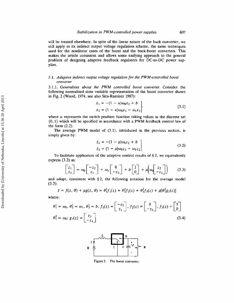
3.1.1. Generalities about the PWM controlled boost converter. Consider thefol1owing normalized state variable representation of the boost converter shownin Fig. 2 (Wood, 1974, see also Sira-Ramirez 1987):
XI = -(1 - u)woxz + b }(3.1)
Xz = (1 - U)WOXI - WIXZ
where u represents the switch position function taking values in the discrete set{O, I} which will be specified in accordance with a PWM feedback control law ofthe form (2.2).
The average PWM model of (3.1), introduced in the previous section, issimply given by:
Zl = -(1 - Jl)wozz + b }
Zz = (1 - Jl)WOZI - WIZZ
To facilitate application of the adaptive control results of § 2, we equivalentlyexpress (3.2) as:
and adopt, consistent with § 2, the fol1owing notation for the average model(3.3):
i; = fez, e) + Jlg(z, e) = e:ft(z) + e~fz(z) + e~f3(z) + Jl[eigl(z)]
where:
e: = Wo, e~ = WI, e~ = b; ft(z) = [ ~~zJ, fz(z) = [ -~J, h(z) = [~J
ei = wo; gl(Z) = [ Zz ] (3.4)-ZI
L
R
Figure 2. The boost converter.
Dow
nloa
ded
by [
Uni
vers
ity o
f N
ebra
ska,
Lin
coln
] at
15:
36 2
0 A
pril
2013
608 H. Sira-Ramirez et al.
The average equilibrium point of (3.3), for a constant value 11 = U of theduty ratio, is readily obtained from (3.2) as:
wlb bZI = ZI(U) = (1 _ U)2w~; Z2 = Z2(U) = (1 _ U)wo; 11 = U (3.5)
It is easily inferred, from (3.5), that:I
wI 2 (h 2ZI(U) = -b Z2(U) = 1 Z2(U) (3.6)(h
Let us consider, as the output of the average system (3.2), the averagenormalized input current error, computed with respect to its average steady-statevalue:
IWI 2 82 2
Y = h(z) = ZI - Zl(U) = ZI - -b Z2(U) = ZI - 1 Z2(U) (3.7)83
Evidently, system (3.2), with output (3.7), is everywhere a relative degreeone system, except on the line Z2 = O. Notice that a steady-state conditionZ2 = 0 is not achievable in practice. As a matter of fact such a condition isreachable only in the unstable mode of operation for the input current, with11 = 1. This behaviour, incidentally, corresponds to a fixed position of the switchat the value u = 1. We stress that our results are only locally valid for thosecontrolled state trajectories that do not cross the line Z2 = O.
3.1.2. Nonadaptive feedback regulation of the average PWM controlled boostconverter. Imposing on the input current state equation the .asymptotically stablebehaviour:
(3.8)
with CY > 0, one immediately obtains, by simple inversion carried out on the firstequation of (3.2), the computed duty ratio function Ilc as:
WOZ2 - [b + CY (ZI - :1 Z~(U))]Ilc(c) = (3.9)
WOZ2
The actual duty ratio function Il(z) is obtained by limiting the values of thecomputed duty ratio function Ilc to the closed interval [0, 1], in the followingmanner:
(
1 if Ilc(z) ~ 1Il(z) = sat[O,llllc(z):= Ollc(Z) if 0 < Ilc(z) < 1 (3.10)
if Ilc(z) :s; °In steady-state stable operation, the computed duty ratio function takes,
according to (3.9), the value:
Ilc=U=I- b (3.11)WOZ2(U)
which is entirely compatible with (3.5). One further requires that the steadystate value of the duty ratio function be confined to the open interval (0, 1) as
Dow
nloa
ded
by [
Uni
vers
ity o
f N
ebra
ska,
Lin
coln
] at
15:
36 2
0 A
pril
2013

Stabilization in PWM-controlled power supplies 609
demanded by (3.10). One immediately obtains the following (normalized outputvoltage amplification and positivity) conditions:
bZz(U) > - > 0 (3.12)
Wowhich guarantees, at least in steady-state operation, the properness of therelative degree definition.
The zero dynamics, associated with the computed duty ratio function !J.c' areobtained by substituting (3.9) into the second state equation in (3.2), and lettingy = z\ - Z\(U) = z\ - (wdb)Z~(U) become identically zero. One then obtainsthe following nonlinear autonomous dynamics:
. w\Z~(U)Zz = -w\ZZ + (3.13)
Zz
which has only one physically meaningful equilibrium point represented byZz = Zz(U).
Moreover, such an equilibrium point is exponentially asymptotically stable,as can be easily verified from a standard argument on the following Lyapunovfunction candidate (which is strictly positive everywhere except at the equilibrium point, Zz = Zz(U), where its value is zero) and its time derivative,evaluated along the solutions of (3.13):
\ z z 2 .V(z) = 2[ZZ - Zz(U)] :;. V(z) = -2wj V(z)
In view of the saturation limits (3.10) for the proposed duty ratio synthesizer,and the previous arguments, it can be concluded that the non-adaptive controller(3.9), (3.10) locally exponentially asymptotically stabilizes the average inputcurrent behaviour to its equilibrium point while the average normalized outputvoltage also asymptotically exponentially converges to the corresponding equilibrium value, in accordance with (3.5).
3.1.3. Adaptive feedback regulation of the PWM controlled boost converter. Anadaptive version of controller (3.9) requires the introduction of a new unknownparameter which bestows on the input current error (3.7) the hypothesizedlinear parametric dependence of the output, as in (2.4). Indeed we redefine theaverage input current error (3.7) as:
\(h z 3 zY = h(z) = z\ - 1 Zz(U) = z\ - 8 j Z z( U ) (3.14)
83
i.e. in terms of the notation adopted in (2.4) we have: ho(z) = z \ andhj(Z) = -Z~(U).
The average adaptive controller, based on (3.9), can then be obtained interms of the estimated values of the actual parameters, defined in (3.4) and(3.14), as:
and
(3.15)
if Pc(z) "'" 1if 0 < Pc(z) < 1if Pc(z) ~ 0
(3.16)
Dow
nloa
ded
by [
Uni
vers
ity o
f N
ebra
ska,
Lin
coln
] at
15:
36 2
0 A
pril
2013

610 H. Sira-Ramfrez et al.
(3.17)
The regressor vector, corresponding to the proposed adaptive scheme of § 2,is given by:
w = r t;:~~m l= r -f ljl(z)Lg,ho(z) zzjl~z)
ah[(Z) -aZz(U)
which immediately points to the fact that the proposed adaptive scheme doesnot allow the estimation of the parameter 8~ = WI' representing the timeconstant of the RC output circuit. Notice, however, that such a parameter is notpresent in the control law (3.15) and, hence, lack of knowledge about thisparameter is irrelevant for control purposes.
The corresponding parameter adaptation laws for the average PWM controlled system are readily obtained from (2.6) as:
Al ;"'1)..1;'2 "'3 28[ = -zzy; 8z = 0; 83 = y; 8 1 = zzyjl(z); 8 1 = -aZz(U)y (3.18)
The actual (discontinuous) adaptive PWM controller equations are summarized below:
u = {~
with,
for tk ,,;; t < tk + .u[x(tk)]Tfor tk + jl[x(tk)]T < t,,;; tk + T
tk + T = tk+l; k = 0, 1, 2, ...
(3.19)
where Xz(U) = Zz(U).The parameter update law is obtained from (3.18) as:
"I "I "I "z A "3 Z81 = -xzy; 8z = 0; 83 = y; 81 = xzY/l(x); 81 = -aXz(U)y
(3.20)
(3.21)
(3.22)
3.1.4. Simulation results. Simulations were carried out on a boost converter withnominal circuit parameter values given by R = 11·2, L = 0·195 mH,C = 2000 JLF and E = 28·0 V, which correspond with the following nominalvalues for the characteristic parameters Wo = 1·601281 X 103 , WI =0·044642 X 103 and b =2·005121 X 103. A desired normalized steady-state output voltage was set to Zz( U) = 2·9525 V, with a corresponding steady statevalue for the duty ratio of U = 0·6. The non-adaptive version of the average andthe actual PWM controller was first simulated. Figure 3 shows the averagenormalized input current and the average normalized output voltage trajectoriessuperimposed on the actual (discontinuous) PWM-controlled responses. Thesampling frequency was set to 10 kHz while the closed loop eigenvalue for thenormalized average input current linearization was chosen as: a =2 X 10³ S-I.
The responses of the actual PWM controlled states are shown to chatter closely
Dow
nloa
ded
by [
Uni
vers
ity o
f N
ebra
ska,
Lin
coln
] at
15:
36 2
0 A
pril
2013

Stabilization in PWM-controlled power supplies 611
3
x/'2
60time (ms)4020
0+- ,-- -----,__-;-;-_......,.:-:-;,-----,o
time (ms) 3020100t----------,--------,--------:-;-----;--,-----,o
0.5
Figure 3. Non-adaptive average normalized input current and average normalized outputvoltage trajectories superimposed on the actual (discontinuous) PWM-controlled reosponses for the boost converter.
about the average trajectories with quite close convergence toward the desiredequilibrium. The very small discrepancies, and biases, existing between theaverage and the actual PWM controlled responses are explainable in terms ofthe fact that a finite sampling frequency is being used, together with theinherent modelling error represented by the use of an average-based duty ratiosynthesizer. Figure 4 shows the average and the actual PWM-controlled statetrajectories obtained when the adaptive version of the PWM controller is used.The desired equilibrium value is now perfectly achieved for both the averageand the actual PWM controlled normalized input current, but without the smalldiscrepancies noticed before in the non-adaptive case. This is, precisely, one ofthe beneficial effects of the proposed adaptation scheme. Figure 5 depicts theobtained trajectories for the adaptive controller parameters in the actual PWMcontrolled system. In general, as inferred from the general results of theadaptation method, the steady state values of these parameters may not coincidewith the actual (i.e. true) parameter values used for the simulation of the plant.
3.2. Direct output voltage regulation for the PWM controlled boost converterIt will now be shown that a (direct) normalized output voltage regulation for
the boost converter is infeasible, if one resorts to input-output linearizationschemes based on partial inversion of the converter system equations.
Indeed if one adopts, as the output of the boost converter circuit, the outputvoltage error with respect to its steady state value, i.e.
y = Z2 - 2 2 (U) (3.23)
Dow
nloa
ded
by [
Uni
vers
ity o
f N
ebra
ska,
Lin
coln
] at
15:
36 2
0 A
pril
2013

612 H. Sira-Ramirez et al.
3
time (ms) 604020
0+- ---,-- -r-r-' ----.,._..,....----,
o
5 10 .time (ms) 15
Figure 4. Adaptively controlled average, and actual state trajectories for the boost converterexample.
1. 51 1.62
el=~ 1. 618 et=~1.5
1. 616
1. 49
time (ms)1. 614
0 10 20 30 0 10
1.985
1.98 0
1.975e1 =b
IeT =Oll/b
1.97
-0.1
11. 9651
lime (ms) -Q.2j lime (ms)i 1 i i i i
0 10 20 30 0 10 20 30
Figure 5. Trajectories for the adaptive controller parameters of the actual PWM-controlledboost converter.
Dow
nloa
ded
by [
Uni
vers
ity o
f N
ebra
ska,
Lin
coln
] at
15:
36 2
0 A
pril
2013

Stabilization in PWM-controlled power supplies 613
then, it easily follows that the resulting system is everywhere relative degreeone, except on the line Z I = 0.
Imposing on the normalized output voltage state equation the asymptoticallystable behaviour:
Zz = -(1' [zz - Zz(U)] (3.24)
with (1' > 0, one immediately obtains, by simple inversion carried out on thesecond state equation of (3.2), the computed duty ratio function Jic as:
WOZI - WIZZ + (1' (zz - Zz( V»Jic(z) = (3.25)
WOZI
The associated zero dynamics is obtained by substituting the expression(3.25) into the first state equation in (3.2), and letting y = Zz - Zz( V) be zero.One then obtains:
. WIZ~(U)ZI = b - (3.26)
ZI
which has a unique equilibrium point given by Z I = Z 1(V) = WI Z ~(U)/b. It iseasy to verify, by straightforward linearization, that such an equilibrium point isunstable and, thus, the system is non-minimum phase. This fact renders anyadaptation scheme based on (3.25) totally infeasible.
3.3. Adaptive indirect output voltage regulation for the PWM controlledbuck-boost converter
3.3.1. Generalities about the PWM controlled buck-boost converter. Consider thefollowing normalized state representation of the buck-boost converter shown inFig. 6 (Sira-Ramirez 1987):
Xl = (1 - u)woxz + ub }
Xz = -(1 - u)wo XI - WIXZ
where u takes values in the discrete set {O, 1}.The average PWM model of (3.27) is given by:
ZI = (1 - Ji)wozz + Jib }
ZZ = -(1 - Ji)wo ZI - WtZZ
which may also be equivalently expressed as:
(3.27)
(3.28)
(3.29)
E+ L
R
Figure 6. The buck-boost converter.
Dow
nloa
ded
by [
Uni
vers
ity o
f N
ebra
ska,
Lin
coln
] at
15:
36 2
0 A
pril
2013

614 H. Sira-Ramire; et aI.
or, as:
z = fez, e) + Jlg(Z, e) = el h(z) + e~ h(z) + p[ei gl(z) + e~ gz(z)]
where:
el = Wo, e~ = Wi> h(z) = [ Zz J, h(z) = [ 0 -1/-Zl -zz_
(3.30)
ei = Wo, e~ = b; gl(z) = [ ~~J, gz(z) = [~J
The average equilibrium points of (3.28), for constant duty ratio p = U, aregiven by:
(3.31)
ue~e~
(el - uei)z'
ue~----;--=------,.. " - Uel - uei' r- -
us»,Z I = Z I (U) = - z z = -,---=---=--,-;;-
(1 - U) Wo
UbZz = Zz(U) = - (1 - U)wo
From where it follows that:I I z
WI ez eze l zZI(U) = -b Zz(U) [Zz(U) - b/wo] = 1 Zz(U) - -I-Z Zz(U) (3.32)
e3 elezThe output of the average system (3.28) is now taken as:
WIy = h(z) = Zl - ZI(U) = Zl - b Zz(U) [Zz(U) - b/wo]
e~ e~ei z= Zl + 1 Zz(U) - -I-Z Zz(U) (3.33)
e3 elez
Evidently, system (3.28), with output (3.33), is everywhere a relative degreeone system, except on the line wozz = b. Our results are only locally valid forthose controlled state trajectories that do not cross the above line.
3.3.2. Non-adaptive feedback regulation of the average PWM controlled buckboost converter. Imposing on the input current state equation an asymptoticallystable behaviour:
ZI = -a [ZI - ZI(U)] = -a [ZI - :1 Zz(U) (Zz(U) - b/wo)] (3.34)
with a> 0, one immediately obtains, by simple inversion carried out on the firstequation of (3.2), the computed duty ratio function Pc as:
WoZz + a (ZI - ZI(U»Pc(z) = w b
oZz - (3.35)eh + a[ZI + (eYehzz(u) - (e~ei/ele~)z~(U)]
=eizz - e~
The actual duty ratio function p(z) is simply obtained as before by:
(
1 if Pc(z) ;;. 1p(z) = satl0.!] Pc(z):= Pc(z) if 0 < Pc(z) < 1 (3.36)
o if Pc(z) ,,;;; 0
Dow
nloa
ded
by [
Uni
vers
ity o
f N
ebra
ska,
Lin
coln
] at
15:
36 2
0 A
pril
2013

Stabilization in PWM-controlled power supplies 615
In steady-state stable operation, the computed duty ratio function takes,according to (3.9), the value:
WoZz(U) > 0 > -b ~ woZz(U) + b > 0 (3.38)
which guarantees, at least in steady-state operation, the properness of therelative degree definition.
The zero dynamics is obtained in this case as:
. bwIZI(U)Zz = -WIZZ + b (3.39)
WoZz -
which has only one physically meaningful equilibrium point represented by thepositive solution Zz = Z z(U) of:
z b ZI(U)Zz - - Zz - b = 0
Wo WI
Moreover, such an equilibrium point is locally asymptotically stable, as canbe easily verified from a standard argument on the following Lyapunov functioncandidate and its time derivative along the solutions of the zero dynamicsdifferential equation (3.39):
[z b bZI(U)]z. [zz - bl(2Wo)]
V(z) = ! Zz - - Zz - ~ V(z) = -2wI bl V(z)Wo WI Zz - Wo
Notice that for Zz > bl(2wo) the function:
[z z - bl(2Wo)]
Zz - blwo
is strictly positive and bounded above by 1; hence, for initial conditions specifiedaround the assumed positive equilibrium point for Zz, the trajectories of the zerodynamics asymptotically converge towards such an equilibrium point.
3.3.3. Adaptive feedback regulation of the PWM controlled buck-boost converter. An adaptive version of the controller (3.35), (3.36) again requires theintroduction of new unknown parameters which make the input current errorsatisfy the hypothesized linear parametric dependence of the output. We thusredefine the average input current error (3.33) as:
y = h(z) = Zl - ZI(U) = ZI + OiZz(U) - O~Z~(U) (3.40)
with:
01 e/leze3 _ ~. e3__Z_I
I - er z - ele~ (3.41)
i.e. in terms of the notation adopted in (2.4) we have: ho(z) = ZI andhl(Z) = Zz(U), hz(Z) = -Z~(U).
Dow
nloa
ded
by [
Uni
vers
ity o
f N
ebra
ska,
Lin
coln
] at
15:
36 2
0 A
pril
2013

616 H. Sira-Ramire; et al.
(3.43)
(3.44)
(3.45)
The average adaptive controller, based on (3.35), can then be obtained interms of the estimated values of the actual parameters, defined in (3.30) and(3.41), as:
(3.42)
and
(
1 if Pc(z) "" 1P(z) = satlo.11 PC<z):= Pc(z) if 0 < Pc(z) < 1
o if Pc(z) "" 0The regressor vector, corresponding to the proposed adaptive scheme of § 2,
is given by:
Lf,ho(z) Z2Lf,ho(z) 0
w = P(z)Lg,ho(z) = -Z2P(Z)P(z)Lg,ho(z) P(z)
ahl(Z) aZ2~U)
ah 2(Z) - a Z2(U)
The corresponding parameter adaptation laws for the average PWM controlled system are readily obtained from (2.6) as:
Ai Ai "'2 A.}..2 A.
8 1 = Z2Y; 82 = 0; I'll = - Z2Yf1(Z); 82 = f1(z)y;"3 "3 2I'll = aZ2(U)y; 82 = - a Z 2( U)y
The actual (discontinuous) adaptive PWM controller equations are summarized below:
u = {~
with,
for t« "" t < tk + P[x(tk»)Tfor tk + P[x(tk»)T < t "" tk + T
tk + T = tk+l; k = 0, 1, 2, ...
(3.46)
(3.47)
(3.48)
(3.49)
where X 2(U) = Z2(U),Ai Al "'2 A}..2 A.
8 1 = x2Y; 82 = 0; 81 = -X2Yf1(X); 82 = f1(x)y"3 "3 28] = aX2(U)y; 82 = -aXz(U)y
3.3.4. Simulation results. Simulations were carried out on a buck-boost converter with nominal circuit parameter values given by R = 1·12 Q, L =0·195 mH, C = 2000 IJ.F and E = 28 V, which correspond to the followingnominal values for the characteristic parameters Wo = 1·601281 X 103,
WI = 0·44642 X 103 and b = -2·005121 X 103. A desired normalized steady-state
output voltage was set to Z2(U) = 1·8783 V, with a corresponding steady-statevalue for the duty ratio of U = 0·6. The non-adaptive version of the average and
Dow
nloa
ded
by [
Uni
vers
ity o
f N
ebra
ska,
Lin
coln
] at
15:
36 2
0 A
pril
2013

Stabilization in PWM-controlled power supplies 617
the actual PWM controller was first simulated. Figure 7 shows the non-adaptively controlled average normalized input current and the corresponding average normalized output voltage trajectories superimposed on the actual(discontinuous) PWM controlled responses. The sampling frequency was set to10 kHz while the closed loop eigenvalue for the normalized average inputcurrent linearization was chosen as: (l' = 2 X 10³ S-I. The actual PWM-controlled responses are shown to chatter closely about the average trajectorieswhich exhibit asymptotic convergence towards the desired (average) equilibrium.As before, a small bias may be noticed in the chattering response of the averageinput inductor current with respect to the corresponding average steady-stateresponse. This is due to the finite sampling frequency being used and the'modelling error' effect of the infinite frequency average-based controller. Figure8 shows the average and the actual state trajectories obtained when the adaptiveversion of the PWM controller is used. Again, the desired equilibrium value isachieved for both the average and the actual adaptive PWM controlled normalized output voltage. No noticeable discrepancies, or steady state biases, existbetween the average and the actual PWM-controlled state responses. Figure 9depicts the obtained trajectories for the adaptive controller parameters in theactual PWM controlled converter.
3.4. Direct output voltage regulation for the PWM controlled buck-boostconverter
It is now shown that a normalized output voltage regulation for thebuck-boost converter is infeasible if one resorts to input-output linearizationschemes based on partial inversion of the converter system equations.
o
~.",.o",,,,,,,,~,,"",,,,,,,,",~;,;;;,,_ ""~o 2 4 6 time (ms) 8
Figure 7. Non-adaptive average normalized input current and average normalized outputvoltage trajectories superimposed on the actual (discontinuous) PWM-controlled responses for the buck-boost converter.
Dow
nloa
ded
by [
Uni
vers
ity o
f N
ebra
ska,
Lin
coln
] at
15:
36 2
0 A
pril
2013

618 H. Sira-Ramirez. et al.
2
-1
I~
o 2 4 6 time (ms) 8
Figure 8. Adaptively controlled average, and actual state trajectories for the buck-boostconverter example.
6
lime (ms)
42
0.3+-_---.__-.-__,--_
o
1.5C\:91=~1.499
---=T=.""024
642
-0.2
-0.22
-0. 24 +---=:::::::::.,r------,-~~=
o642
1.7006
1.7002
1. 6998 +--====--r------,---,-o
-2.096
-2.098 9~=b
42
-2. 1.j-__~_---.__':"';"~
o
Figure 9. Trajectories for the adaptive controller parameters of actual PWM-controlledbuck-boost converter.
Dow
nloa
ded
by [
Uni
vers
ity o
f N
ebra
ska,
Lin
coln
] at
15:
36 2
0 A
pril
2013

Stabilization in PWM-controlled power supplies 619
Indeed if one adopts, as the output of the buck-boost converter circuit, theoutput voltage error with respect to its steady state value, i.e.
y = Zz - Zz(U)
A desired output voltage dynamics of the form:
Zz = -(1" [zz - Zz(U)]
with (1" > 0, yields the following computed duty ratio function /-le as:
WoZI + WIZZ - a(zz - Zz(U»/-le(z) = ---"..-:c-_-'-.:..::_----'---'=----_-"-'----'..:....WOZI
The associated zero dynamics is now:
. wIZz(U)[Zz(U) - b/wo]Z I = b - --e-----=-'-----'-=----=-'-----'_'-----'_'"
ZI
(3.50)
(3.51)
(3.52)
(3.53)
which has a unique equilibrium point given by Z I = Z I (U) =wI!b Zz(U)[Zz(U) - b/wo]. It can be verified that such an equilibrium point isunstable and, thus, the system is non-minimum phase. This fact renders anyadaptation scheme based on (3.52) totally unfeasible.
3.5. Adaptive indirect output voltage regulation for the PWM controlled buckconverter
We now summarize the equations and steps leading to an adaptive indirectoutput voltage regulation for a PWM controlled buck converter (see Fig. 10).
Normalized state representation of the buck converter (Wood 1974, Sira-Ramirez1987):
XI = -WOXz + ub
Xz = WOXI - WIXZ
Average PWM model
ZI = -WoZz + ub
Zz = WOZI - WIZZ
or:
Z = fez) + /-lg(z) = e~ !I(z) + e~ fz(z) + /-l[ei gl(z)]
(3.54)
(3.55)
(3.56)
E+
Figure 10. The buck converter.
R
Dow
nloa
ded
by [
Uni
vers
ity o
f N
ebra
ska,
Lin
coln
] at
15:
36 2
0 A
pril
2013

620
with:
H. Sira-Ramire; et al.
o( = Wo, 01 = WI; fl(z) = [-zzJ, fz(z) = [ 0 JZj -Zz
oi = b; gj(Z) =[~JA verage equilibrium point
Uwjb u010iZI = 2 1(U) = --z- = --I-Z
Wo (0 1)
uoiZz = 2 2(U) = Of =; /l = U
Output function for the average systemI
WI 0zY = h(z) = ZI - 2 1(U) = ZI - - 2 z(U) = 2 1 - 1 2 z(U)
Wo OJ
Output equation with linear parametrization for the purposes of adaptationI
Oz 3Y = h(z) = ZI - 1 2 z(U) = ZI - 012z(U)01
Desired input current dynamics
Zj = -£1' [ZI - 2 1(U)] = -£1' [ZI :~ 2 z(U)] = -£1' [ZI :t 2 z(U)]
with £1' > O.
The computed duty ratio function
WoZz - £1' [ZI - (wdwo)2z(U)]/lc(z) = b
O(zz - £1' [Zj - (0i/0j)2 z(U)]
oi
(3.57)
(3.58)
(3.59)
(3.60)
(3.61)
Actual duty ratio function
/l = sat[o.1)Ilc := UcSteady-state computed duty ratio function
if /lc "" 1if 0 < /lc < 1if /lc .,;; 0
(3.62)
Wo/lc = U = b 2 z(U) (3.63)
Normalized output voltage attenuation and positivity conditions arising from0</l=/lc<1
b0<2z(U)<
Wo
Zero dynamics (exponentially asymptotically stable)
Z2 = - WI [zz - :: 2 j(U)] = -WI[ZZ - 2 z(U)]
(3.64)
(3.65)
Dow
nloa
ded
by [
Uni
vers
ity o
f N
ebra
ska,
Lin
coln
] at
15:
36 2
0 A
pril
2013

Stabilization in PWM-controlled power supplies
Adaptive average controller~1 ~3
81zZ - a- [ZI - 81ZZ(U)]~z
81
if fle .,. 1if 0 < fle < 1if fle "" 0
The regressor vector
_[ Z~:~ ] _[ -~z lw - ~L h - ~
:h1(Z) -a-:z(U)
The parameter adaptation laws for average PWM-controlled systemAl Al AZ A381 = -y zz; 8 z = 0; 8 1 = yfl; 8 1 = -Cl"yZz(U)
Discontinuous adaptive PWM controller
621
(3.66)
(3.67)
(3.68)
(3.69)
u = {~ for tk "" t < tk + fl[x(tk)]Tfor tk + fl[x(tk)]T < t « tk + T
tk + T = tHl; k = 0, 1,2, ...
(3.70)
Parameter update lawsAl ;"1;"2 A )..381 = -xzy; 8 z = 0; 8 1 = Y/l(x); 81 = -Cl"yZz(U)
(3.71)
(3.72)
(3.73)
Simulat.on resultsSimulations were carried on a buck converter with nominal circuit parameter
values given by R =0·81 Q, L =0·20 mH, C = 500·0 JLF and E = 63·28 V,which correspond to the following nominal values for the characteristic parameters Wo = 3·1623 X 103 , WI =2·4691 X 103 and b = 4·4746 X 103 . A desirednormalized steady-state output voltage was set to Z z(U) = o·7794 V, with acorresponding steady-state value for the duty ratio of U =0·5. Figure 11 showsthe average normalized input current and the average normalized output voltagetrajectories superimposed in the actual (discontinuous) non-adaptive PWMcontrolled responses. The sampling frequency used was set to 20 kHz and theclosed loop eigenvalue for the normalized average input current linearizationwas chosen as Cl" = 3 X 10³ S-I. Convergence toward the desired equilibriumnormalized input current is obtained for the average PWM controlled responseswhile the actual (i.e. discontinuous) non-adaptive PWM controlled responsesexhibit very small discrepancies with respect to the average response. Figure 12shows the average and the actual state trajectories obtained when the adaptiveversion of the PWM controller is used. Again, the desired equilibrium value is
Dow
nloa
ded
by [
Uni
vers
ity o
f N
ebra
ska,
Lin
coln
] at
15:
36 2
0 A
pril
2013

622 H. Sira-Ramfrez et al.
0.8
0.6
0.4
0.2
time (ms)
5432
o¥-- ---,- ,- ----.- .- ----,a
Figure 11. Non-adaptive average normalized input current and average normalized outputvoltage trajectories superimposed on the actual (discontinuous) PWM-controlled responses for the buck converter.
5
time (ms)
432
o¥- ,-- ,-- ,-- -,-- ----,
°
0.6
0.8
0.4
0.2
Figure 12. Adaptively controlled average, and actual state trajectories for the buck converterexample.
Dow
nloa
ded
by [
Uni
vers
ity o
f N
ebra
ska,
Lin
coln
] at
15:
36 2
0 A
pril
2013
Stabilization in PWM-controlled power supplies 623
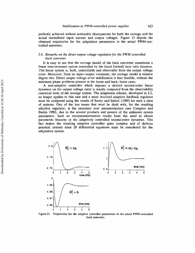
perfectly achieved without noticeable discrepancies for both the average and theactual normalized input current and output voltages. Figure 13 depicts theobtained trajectories for the adaptation parameters in the actual PWM-controlled converter.
3.6. Remarks on the direct output voltage regulation for the PWM controlledbuck converter
It is easy to see that the average model of the buck converter constitutes alinear time-invariant system controlled by the (hard limited) duty ratio function.This linear system is, both, controllable and observable from the output voltageerror. Moreover, from an input-output viewpoint, the average model is relativedegree two. Direct output voltage error stabilization is thus feasible, without theminimum phase problems present in the boost and buck-boost cases.
A non-adaptive controller which imposes a desired second-order lineardynamics on the output voltage error is readily computed from the observabilitycanonical form of the average system. The adaptation scheme, developed in § 2,no longer applies to this case and a more involved adaptive feedback regulatormust be computed using the results of Sastry and Isidori (1989) for such a classof systems. One of the key issues that must be dealt with, for the resultingadaptive regulator, is the necessary over parametrization (see Campion andBastin 1990), due to the several products and powers of the unknown systemparameters. Such an overparametrization results from the need to obtainparametric linearity in the adaptively controlled second-order dynamics. Thisfact makes the resulting adaptive controller quite complex and of dubiouspractical interest since 28 differential equations must be considered for theadaptation system.
4 5
time(ms)
32o.9+-_,------,_--,_---,_--,
o
54
4 5time (ms)
3
3
9T =b
2
2
91 l-~
2.8
2.78
2.76
0
5
4.99
4.98
4.97
4.96
0
Figure 13. Trajectories for the adaptive controller parameters of the actual PWM-controlledbuck converter.
Dow
nloa
ded
by [
Uni
vers
ity o
f N
ebra
ska,
Lin
coln
] at
15:
36 2
0 A
pril
2013

624 H. Sira-Ramire; et al.
4. Conclusions and suggestions for further workIn this article, a general adaptive feedback regulation scheme for PWM
controlled DC-to-DC power converters has been proposed. The treated casesincluded the buck, the boost and the buck-boost converters. Using modernnonlinear feedback controller design techniques, based on partial linearizationand system inversion, a non-adaptive regulator is developed for the averagePWM system which indirectly stabilizes the output load voltage, to a desirableconstant equilibrium point, through an input current stabilization strategy. Inorder to avoid non-minimum phase problems, the proposed adaptive controllersnecessarily process input current error information, computed in terms of therequired steady state value of the output voltage, rather than directly operatingon the basis of the output voltage error information. The non-adaptive averagemodel based design strategy is shown to yield feedback controlled stateresponses which represent a rather good approximation to the actual discontinuous PWM controlled responses, with very small steady-state errors. The actualdiscontinuous adaptive PWM controlled responses are generally shown to yieldimproved feedback controlled state responses which are in almost perfectsteady-state agreement with the (ideal) adaptive average PWM-controlled responses. Thus, adaptation is seen to compensate effectively not only forunmodelled parameter variations but also for the errors inherent in the actualuse of an average-based feedback controller design.
Some other non-adaptive feedback regulation schemes for PWM controlledDC-to-DC power supplies, such as those based on either linear or nonlinear PD,PI and PID actions may also be made adaptive using techniques similar to thosedeveloped in this preliminary study (see Sira-Ramirez 1990, 1991a). Adaptivedynamical feedback regulation, based on dynamical duty ratio synthesizers, canbe developed for DC-to-DC converters along similar, but certainly moreinvolved, lines (see Sira-Ramirez and Lischinsky-Arenas 1991 and Sira-Rarnirezet al. 1992).
ACKNOWLEDGMENT
This work was supported by the Consejo de Desarrollo Cientffico, Humanfstico y Tecnol6gico of the Universidad de Los Andes under Research Grants1-362-91 and 1-358-91.
REFERENCES
CAMPION, G., and BASTIN, G., 1990, Indirect adaptive state feedback control of linearlyparametrized non-linear systems. International Journal of Adaptive Control SignalProcessing, 4, 345-358.
CSAKI, F., GANSKY, K., IpSITZ, I., and MARTI,S., 1983, Power Electronics (Budapest,Hungary; Akademia Kiado).
IEEE Power Electronics Specialists Conference Records.KANELLAKOPOULOS, I., KOKOTOVIC, P. Y., and MARINO, R., 1989, Robustness of adaptive
nonlinear control under and extended matching condition. In Proceedings of the IFACSymposium Nonlinear Control of Systems Design (NOLCOS), Capri, italy,pp. 192-197.
KANELLAKOPOULOS, I., KOKOTOVIC, P. Y., and MORSE,S., 1991, Systematic design ofadaptive controllers for feedback Iinearizable systems. IEEE Transactions on Automatic Control 36, 1241-1253.
Dow
nloa
ded
by [
Uni
vers
ity o
f N
ebra
ska,
Lin
coln
] at
15:
36 2
0 A
pril
2013

Stabilization in PWM-controlled power supplies 625
KASSAKIAN, J. G., SCHLECHT, M. F., and VERGHESE, G. c., 1991, Principles of PowerElectronics (Reading, Mass: Addison-Wesley).
KOKOTOVIC, P. V., 1991, Foundations of Adaptive Control. Lecture Notes in Control andInformation Sciences (Berlin: Springer-Verlag).
KREIN, P. T., BENTSMAN, J., BAss, R. M., and LESIEUTRE, B. L., 1990, On the use ofaveraging for the analysis of power electronics systems. IEEE Transactions on PowerElectronics,S, 182-190.
MIDDLEBROOK, R. D., and CUK, S., 1981, Advances in Switchedmode Power ConverterCircuits (Pasadena, Calif.: Tesla); 1983, Advances in Switchedmode Power ConverterCircuits (Pasadena, Calif.: Tesla).
MOHAN, N., UNDELAND, T. M., and ROBBINS, W. P., 1989, Power Electronics, Converters,Applications and Design (New York: Wiley).
NARENDRA, K., and ANNASWAMMY, A., 1989, Stable Adaptive Systems (Englewood Cliffs, NJ:Prentice Hall).
SASTRY, S. and BODSON, M., 1989. Adaptive Control (Englewood Cliffs, NJ: Prentice Hall).SASTRY, S.. and [SIDORI, A., 1989, Adaptive control of linearizable systems. IEEE Transac
tions on Automatic Control, 34, 1123-1131.SEVERNS, R. P. and BLOOM, G., 1985, Modern DC-to-DC Switchmode Power Converter
Circuits (New York: Van Nostrand-Reinhold).SIRA-RAMfREZ, H., 1987, Sliding motions in bilinear switched networks. IEEE Transactions on
Circuits and Systems, 34, 919-933; 1988, Sliding motions on slow manifolds of systemswith fast actuators. International Journal of Systems Science 47, 875-887; 1989a,Switched control of bilinear converters via pseudolinearization. IEEE Transaction onCircuits and Systems, 36, 858-865; 1989b, A geometric approach to pulse-widthmodulated control in nonlinear dynamical systems. IEEE Transactions on AutomaticControl, 34, 184-187; 1990, International Journal of Control, Design of P-I controllersfor de-to-de power supplies via extended linearization, 51, 601-620; 1991 a NonlinearP-I controller design for switch-mode de-to-de power converters. IEEE Transactionson Circuits and Systems, 38, 410-417. 1991b, Nonlinear dynamically feedback controlled descent on a non atmosphere-free planet: a differential algebraic approach.Control: Theory and Advanced Technologies 7, 301-320; 1991c, Nonlinear dynamicalfeedback strategies in aerospace systems control: a differential algebraic approach.Proceedings of First European Control Conference, Grenoble, France, Vol. 3,pp.2038-2043.
SIRA-RAMiREZ, H., and IUC-SPONG, M., 1988, A geometric approach to the feedback controlof switchmode de-to-de power supplies. IEEE Transactions on Circuits and Systems,35, 1291-1298; 1989, Exact linearization in switch mode de-to-de power converters.International Journal of Control, 50, 511-524.
SIRA-RAMfREZ, H., and LISCHINSKy-ARENAS, P., 1990, Dynamical discontinuous feedbackcontrol of nonlinear systems. IEEE Transactions on Automatic Control 35, 1373-1378;1991, The differential algebraic approach in nonlinear dynamical compensator designfor de-la-de power converters. International Journal of Control, 54, 111-134.
SIRA-RAMfREZ, H., LISCHINSKy-ARENAS, P., and LLANES-SANTIAGO, 0., 1993, Dynamicalcompensator design in nonlinear aerospace systems. IEEE Transactions on Aerospaceand Electronic Systems (to be published).
SIRA-RAMfREZ, H., and PRADA-RIZZO, M. T., 1992, Nonlinear feedback regulator design forthe Cuk converter. IEEE Transactions On Automatic Control 37, 1173-1180.
SIRA-RAMfREZ, H., ZRIBI, M., and AHMAD, S., 1992, Adaptive dynamical feedback regulationstrategies for linearizable uncertain systems. International Journal of Control, to bepublished.
TEEL, A., KADlYALA, R., KOKOTOVIC, P. V., and SASTRY, S., 1991, Indirect techniques foradaptive input-output linearization of non-linear systems. International Journal ofControl, 53, 193-222.
UTKIN, V. I., 1978, Sliding Modes and Their Applications in Variable Structure Systems(Moscow: MIR).
WOOD, J. R., 1974, Power conversion in electrical networks. NASA Report No. CR-120830,Harvard University Division of Engineering and Applied Physics, Cambridge, Massachusetts.
Dow
nloa
ded
by [
Uni
vers
ity o
f N
ebra
ska,
Lin
coln
] at
15:
36 2
0 A
pril
2013