Ad830 user manual
47
AD830 DUAL-NET ALARM HOST SYSTEM User Manual
-
Upload
hai-andre-boukris -
Category
Documents
-
view
54 -
download
0
Transcript of Ad830 user manual

AD830 DUAL-NET ALARM HOST SYSTEM
User Manual

Preface
Preface
We sincerely gratitude your trust to purchase our “AD830 Alarm Control Panel”series product, and hope the product can give great convenience and guarantee to your safety.
If you require the latest product performance or function, please contact your sales directly !
User Manual
“AD 830 Alarm Control Panel” system introduces international most advanced digital sensor and control technique, is an integrated smart alarm control system combined anti-burglar, fire, gas leak and other applications, totally compatible with wire and wireless two alarm methods. Full process with voice prompt, no complicated memory
“AD 830 Alarm Control Panel” system takes advantage of international most advanced multi-digit random code hopping tech in safety and reliability performance, effectively solved the problems of interference, false alarm and miss alarm from other systems. “AD 830 Alarm Control Panel” system uses international common ADEMCO CONTACT ID method to send alarm signal, expanding its application range and compatibility. The system can be widely applied in home, community, villa, shops, and
Please read this manual carefully, you can know what the product is and how to use it.
command, easy-operation, easy to learn and use.
public working place, etc.
Content
Content
Accessory List
Chapter 1 Product Overview
1.1 Function
1.2 About Panel
1.3 About Icons
Chapter 2 Installation and Wire Connection
2.1 Open the box
2.2 Install the control panel
2.3 Wire Connection
2.4 Install Wired Detector
2.5 Install Wireless Detector
Chapter 3 GSM Setting&Operation
3.1 Choose GSM Wire and Tel-line Priority
3.2 Check GSM Signal Status
3.3 Exit Setting
3.4 GSM Alarm Receiving& Remote Operation
3.5 GSM SMS Control
3.6 RFID Card SMS Editing
3.7 Alarm Panel GSM Phone Call Function
3.8 Common GSM Suggestions
Chapter 4 Easy Setting&Operation
4.1 Factory Default Setting
4.2 Basic Setting& Operation
4.3 Common Voice Phone Alarm Receiving
4.4 Remote Phone Control
4.5 CMS Alarm Receiving
10
11
1111
10
1
4 .6 Alarm Procedure 4.7 Tel-line Off Alarm 18
User Manual
4.8 Detector Anti Tamper Alarm
4.9 System Event Record &Query
4.10 Easy Operation
4.14 APP Software
Chapter 5 User Setting
Chapter 6 System Setting
Chapter 7 Technical Specification
7.1 General Data
7.2 Physical Property
Chapter 8 Maintenance&Protection
Chapter 9 Porudct Limitation
6.1 Setting Instruction
5.1 Clock Setting
5.3 User Phone Setting
6.2 Main Menu Setting
5.2 User Password Setting
5.4 Zone Attribution Setting
6.3 Password Setting
6.4 CMS Setting
6.5 User Phone Setting
6.6 System Option Setting
6.7 Enroll Wireless Device
6.8 Zone Attribution Setting
6.9 System Maintenance
6.10 Other Setting
6.11 High-level Settings
Content
24
25
25
24
24
25
24
24
2628
28
30
34
37
38
40
41
42
4242
43
43
User Manual
1
.
.
.
.
.
.
..
.
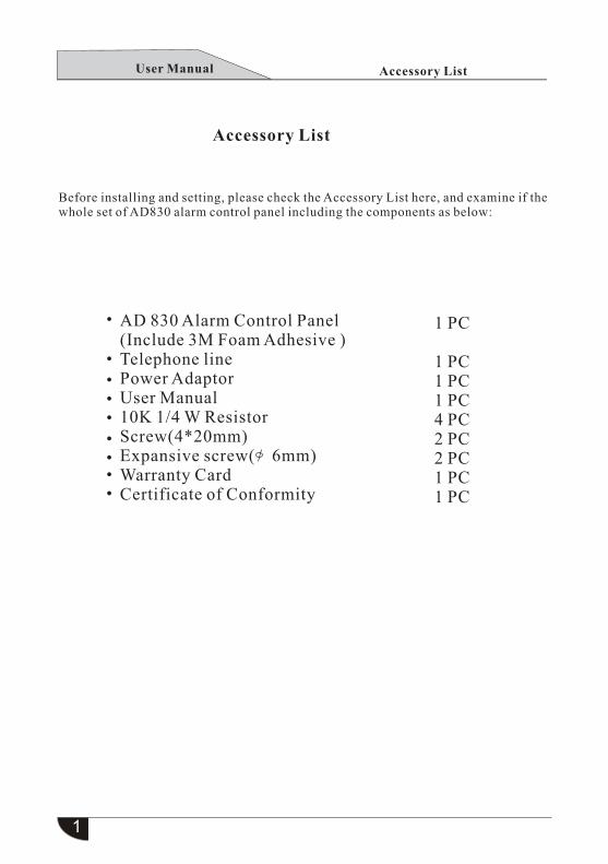
Accessory List
Accessory List
Before installing and setting, please check the Accessory List here, and examine if the whole set of AD830 alarm control panel including the components as below:
AD 830 Alarm Control Panel(Include 3M Foam Adhesive ) Telephone line Power Adaptor User Manual10K 1/4 W ResistorScrew(4*20mm) Expansive screw( 6mm)Warranty CardCertificate of Conformity
1 PC
1 PC1 PC1 PC4 PC2 PC2 PC1 PC1 PC
User Manual
2
Product Overview
Chapter 1 Product Overview
1. Built-in GSM module, with PSTN and GSM network two alarm methods, send signal to alarm center by ADEMCO CONTACT ID protocol, arm/disarm with SMS indication, SMS remote control arm/disarm status, SMS check panel status. PSTN and GSM network priority optional.
2. Full voice prompt: All local or remote operations, alarm information and event record query have corresponding voice prompt.
3. User interface: Large LCD screen indicates every steps of operation, working status, alarm procedure, more convenient and impressive.
1.1 Functions
4. 32 wireless zones: Each zone enables to auto learn code or manually enter address code on keyboard, the panel compatible of all our made wireless detectors, better touse these zones. 5. 4 wired zones: Connect resistor on wired zone terminals to achieve NO /NC alarm.6. Enroll panel series wireless products: The panel can enroll at most 8 remoters, 1 wireless door bell, unlimited one-way wireless sirens.
7. Zone programmable: Every zone of the product has a factory default alarm type. User can modify them if necessary.
8. Enroll wireless devices: All wireless detectors and remote controllers automaticallyenroll code or enter code manually. Each zone can enroll and delete remote controllers separately, or delete all together.
9. Alarm receiving phone number: It can be set 2 CMS phone number and 4 common receiving phone number.
10. Clock: Built-in auto calendar/clock, can be set as local time.
11. Event record and query function: Totally record and check 150 different alarm event messages. Like the time of anti-tamper alarm, detector alarm, arm , disarm, low batterywarning. And also enable to check alarm zone number and alarm type.
12. Password authority: Installer password mainly for administrator to program system,
User Manual
3
Product Overview
user password for common operations as arm, disarm system and remote control, forimproving system’s safety. Both installer and user password can be modified.
13. In central monitoring system, administrator can set 4-digit user number based on different quantity of user.
14. Alarm type auto identify: After alarm triggered, the LCD screen will display zonenumber and alarm type. By networking alarm, panel will report detail zone and alarm type to CMS.
15. Arm/disarm report to CMS : Optional
16. Remote phone control: Via PSTN dialing and password verified to achieve remote control system as operations of arm , disarm, monitor indoor status, system status query.
17. Alarm mode: By standalone phone dialing and GSM, or CMS networking computer (ADEMCO CONTACT ID), both these two methods auto identify and compatible.
18. Anti-cut alarm: To cut off the wire between wired detector and panel the same as to trigger an alarm, the tel-line connect to panel cut off that will auto trigger spot high siren to alarm.
19. Anti-tamper alarm: When someone intends to dismantle the panel deliberately, onceanti-tamper switch triggered , it will alarm immediately.
20. Timing arm/disarm: Enable to set 4 groups timing arm/disarm time, and by the preset times system arm /disarm automatically.
21. Timing test: According to preset time, send message to CMS to check the panel online working status.
User Manual

4
Product Overview
22. Voice phone alarm receiving: Alarm can via dialing user’s preset phone number, to tell user alarm information.
23. Spot siren optional: Built-in siren, and our wireless high siren, both of them can set on or off according to user’s demand.
24. Voice speaker volume adjustable: Long press 1 to enter volume setting, press to plus, press to minus.
25. Wire/wireless zone realtime monitor: Enable the option, while arming or disarming, voice will indicate zone trouble status.
26. Wireless repeat relay function: Our made wireless repeater can achieve panelreceiving signal from detector more stable .
27. Wireless detector low battery warning: When detector battery undervoltage, it will send status report to panel every 1 to 2 hours, if alarm situation happens, LCD screen will display corresponding zone number and battery low voltage icon to remind user, and report to CMS.
28. Press SOS key on the panel or remote to set panel built-in siren whistle or not.(Refer to 00 zone siren type)
29. During panel remote operating, enter 4-digit user password firstly, in case unauthorized user to operate it.
30. Networking: PSTN and GSM two networks available, which one priority in use is up to user.
31. Wireless door bell: Optional( this option takes up one zone)
32. GSM phone call function
33. RFID card SMS programmable34. Support spot 15s recording function35. Support portable mobile device APP software control.
User Manual

M DY
M DY
SOS
RFID
1 ~ 0
LCD Screen
Arm
Disarm
Home Arm
Time
Date
Sending Alarm
Sending to mobile
RFID Card Sense Area
Panic key
Alarm indicator
Fault indicator
One / Volume
Arm/Up key
Disarm/Down key
5
M DY
1 2 3
4
7
5
8
0
6
9
SOSRFID
+
-
Numeric Keyboard
Confirm
Zone Setting
LCD Screen
Alarm Indicator
SOS
Play
Fault Indicator
Record
Dial Key
Back
Panel
RFID Card Area
Home Arm/Pause
Event Query/Delete
Product Overview
1.2 About Panel
1.3 About Icons
Away Arm/UpDisarm/Down
Siren whistle
GSM network signal
Terminal Power
SOS
TEL-line status
Alarm indication
Panel Power
Numeric keys
Home arm/ Pause Key
Event query/Delete key
Back
Confirm
Zone setting
Record
Play
Dial key
User Manual
6
Bracket
Mounting Knockout
InstallDirection
Mounting Hole
Installation& Wire Connection
Chapter 2 Installation & Wire Connection
2.1 Open the box Open the package to check accessory missing or not (refer to Accessory List), if you have found accessory missed, please contact local distributor or supplier immediately.
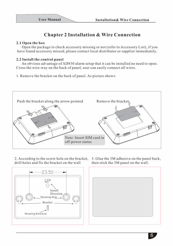
2.2 Install the control panel An obvious advantage of AD830 alarm setup that it can be installed no need to open. Cross the wire-way on the back of panel, user can easily connect all wires.
1. Remove the bracket on the back of panel. As picture shows:
Push the bracket along the arrow pointed Remove the bracket
Note: Insert SIM card in off-power status
2. According to the screw hole on the bracket, drill holes and fix the bracket on the wall
3. Glue the 3M adhesive on the panel back, then stick the 3M panel on the wall.
User Manual
Metal
10k
10k
7
10k
10k
12V
GND
BELL+
GND
Z33
Z34
COM
COM
Z35
Z36
NC(Recommend)
Wired siren( ≤350mA)
LINE
TEL Correspondenceexternal wire
Telephone
POWER:DC15V 2A
Installation& Wire Connection
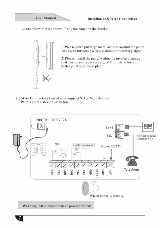
1. Please don’t put large metal articles around the panel, in case to influence wireless detector receiving signal.
2. Please install the panel within the invalid distance that can normally receive signal from detector, and better putit in a covert place.
As the below picture shows: Hang the panel on the bracket.
2.3 Wire Connection (wired zone support NO or NC detector) Panel external devices as below:
NOOutput DC12V
Warning: All connectors have power limited!
User Manual
8
Installation& Wire Connection
2.4 Install wired detector
2.4.1 Wired zone has defaulted as bypass status, user can modify it into effective status if necessary. If wired zone faulted while arming, user will hear “Operation failed, zone fault”. And the LCD will display the fault zone number+ E, now better not to arm.
2.4.2 The panel can power 12V, 700mA to detectors, don’t exceed 700 mA max current, or detector need adopt extra DC12V backup power.
2.5 Install wireless detector
2.5.1 As the detector’s manual states, install coded detector in the open area 100~120m away from the control panel. Please take a walk test, make sure the detector can work with control panel normally.
2.5.2 Wireless repeat relay function: When wireless detector is too far or blocked by wall, the panel will disable to receive signal from wireless detector, now you can use our manufactured wireless repeater relay to achieve wireless signal relay transmitting.
User Manual
9
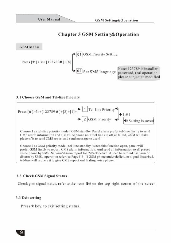
3.1 Choose GSM and Tel-line Priority
3.2 Check GSM Signal Status
3.3 Exit setting
Press key, to exit setting status
Check gsm signal status, refer to the icon on the top right corner of the screen.
01
02
GSM Priority Setting
Set SMS languageNote: 123789 is installerpassword, real operation please subject to modified
Tel-line Priority
GSM Priority
1
2
GSM Setting&Operation
Chapter 3 GSM Setting&Operation
GSM Menu
Press [ ] >3s+[123789 ]+[8]
Press [ ]>3s+[123789 ]+[8]+[1]+
Setting is saved
Choose 1 as tel-line priority model, GSM standby. Panel alarm prefer tel-line firstly to sendCMS alarm information and dial voice phone no. If tel line cut off or failed, GSM will take place of it to send CMS report and send message to user!
Choose 2 as GSM priority model, tel-line standby. When this function open, panel will prefer GSM firstly to report CMS alarm information. And send all information to all preset voice phone by SMS. Set arm/disarm report to CMS effective if need to remind user arm or disarm by SMS, operation refers to Page41! If GSM phone under deficit, or signal disturbed, tel-line will replace it to give CMS report and dialing voice phone.
.
User Manual

10
3.4.1 GSM Alarm Receiving
Panel alarming, GSM sends message firstly, then dial user’s phone number, userwill hear “ system alarm, please receive alarm, cancel alarm press 1, alarm event query press 2, system away arm press 3, disarm the system press 4, system home arm press 5, open the siren press 6, monitor the spot press 7, hang up please press 0 ”. Then press 2 tocheck, voice indicates “xx zone alarm”, only after confirmed it mistake alarm can user delete alarm, and press 1 to end alarm. If operate successfully, follow with voice prompt “operation succeeded”, if not, do it again. Hang up please press 0 ahead. If user no press 1to cancel alarm, and press 0 before hang-up, the panel will dial next voice phone no.(Repeat 5 times if only one phone number and preset dial time is 5)
3.4.2 GSM Remote Operation
User via phone dial the panel GSM to achieve remote control of system arm/disarmand status query. Dial GSM card number, enter password after off-hook, default: 8888, real operation subjects to modified. Follow voice prompt “System away arm press1, disarm the system press 2, system home arm press 3, system status query press 4, spot intercom press 9, hang up please press 0”. If operate successfully, user will hear prompt“operation succeeded”.
3.5 GSM SMS Control
Mobile SMS Arm Command: #pwd8888#ArmMobile SMS Disarm Command: #pwd8888#DisarmMobile SMS Home Arm Command: #pwd8888#HomeMobile SMS Status Query Command: #pwd8888#Check
GSM Setting&Operation
3.4 GSM Alarm Receiving& Remote Operation
Details please refer to this manual 4.3 and 4.4 from Page17 to18
Note: User default password is “8888”, password “8888” no space in it,password is the user modified , when mobile message sent to GSM card of alarm panel, only enrolled mobile number or message wrote right password will receive system reply, others won’t.
User Manual
11
GSM Setting&Operation
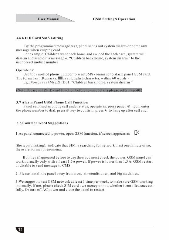
3.6 RFID Card SMS Editing
By the programmed message text, panel sends out system disarm or home arm message when swiping card. For example: Children went back home and swiped the 16th card, system will disarm and send out a message of “Children back home, system disarm ” to the user preset mobile number
Operate as: Use the enrolled phone number to send SMS command to alarm panel GSM card.The format as : (Remarks: is an English character, within 60 words )“” Eg.: #pwd8888#MsgRFID01: “Children back home, system disarm ”
(Note: Please set RFID card function before to use, details please refer Page40 )
3.7 Alarm Panel GSM Phone Call Function Panel can used as phone call under status, operate as: press panel icon, enter the phone number to dial, press key to confirm, press to hang up after call end.
3.8 Common GSM Suggestions
1.As panel connected to power, open GSM function, if screen appears as
(the icon blinking), indicate that SIM is searching for network , last one minute or so, these are normal phenomena.
But they if appeared before to use then you must check the power. GSM panel can work normally only with at least 1.5A power. If power is lower than 1.5 A, GSM restart or disable to send message to CMS.
2. Please install the panel away from iron, air-conditioner, and big machines.
3.We suggest to test GSM network at least 1 time per week, to make sure GSM working normally. If not, please check SIM card owe money or not, whether it enrolled success-fully. Or turn off AC power and close the panel to restart.
User Manual

12
32
01
02
03
04
05
06
07
08~31
Easy Setting &Operation
Chapter4 Easy Setting&Operation
4.1 Factory Default Setting Below are factory defaults of AD 830 Alarm Control Panel, you can keep the defaults or modify them.
GSM function: Enabled Installer password: 123789 User password:8888 Entry and exit delay: 10s Monitoring time: 10s Cycle alarm dialing: 5times Auto off-hook ringing: 7 times (After ringing 7 times panel will pick phone automatically) TEL-line off inspection function: Enabled Auto timing arm/disarm option: Disable Auto timing arm, disarm and inspection time: 00 (The function disabled) Alarm types with siren whistle: Delay, indoor(burglar), perimeter, emergency and 24-hour alarm. All phone no and user code: Empty Siren type of panic zone: Mute Wired zone factory default: Disable
Zone Factory Default
Zone Alarm Type Siren
Table 1:
Perimeter
Delay
Indoor
Indoor
Emergency
24-Hour
Fire
Perimeter
Perimeter
On
On
On
On
Off
On
On
On
On
Zone Default List
Door bell zone: (Optional) Give “ding dong”sound if triggered, occupys one zone
Indoor(Burglar) zone: Enabled only when system under away arm status
Perimeter/delay zone: Enabled under arm and home arm statusGas, fire, emergency zone: Enabled under botharm and disarm status
User better not to set zone siren silent
Delay zone: Mainly applied in zones with entrance or exit.
User Manual
13
M DY
M DY
LCD Screen
Arm
Disarm
Home Arm
Time
Date
Sending alarm
Sending to mobile
Siren whistle
Network signal
Terminal Power
SOS
Wire status
Alarm indication
Panel Power
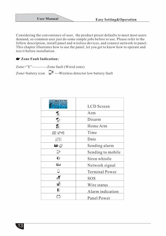
Considering the convenience of user, the product preset defaults to meet most users demand, so common user just do some simple jobs before to use. Please refer to thefollow description, install panel and wireless devices, and connect network to panel. This chapter illustrates how to use the panel, let you get to know how to operate and test it before installation.
Zone Fault Indication:
Zone+”E”-----------Zone fault (Wired zone)
Zone+battery icon ---Wireless detector low battery fault
Easy Setting&OperationUser Manual
14
Easy Setting&Operation
4.2 Basic setting & operation
Basic setting:
The panel has already coded with all remote controllers, magnetic contacts, andpir detectors before left factory, they can auto enter into networking status when connect to power.
Enter system main menu: Press key for 3 seconds, then enter installer password 123789 Enter system sub-menu: Just to press relevant numeric key. Return to previous menu, press key.
System menus all have voice indication, enter main menu the panel will sound all menus option one time. Press [up], [down] key or corresponding number also have voice prompt, more friendly and easy to use. After setting press key to save, you will hear “Setting is saved” , means operate successfully, or failed. On the keyboard from up to down there are four buttons with normal functions [Away Arm], [Disarm], [Home Arm], [Event Record Query], while under system setting status, they function as [Up], [Down], [Pause], [Delete]. The numeric keys on keyboard are for user to enter numbers, key isback, key is confirm. Under panel standby status, press [SOS] key for 3 seconds is toseek emergency help.
Indicator:
Alarm indicator-----light blinking Fault indicator------Indicator light blinking when zone faulted RFID card indicator-----Indicator light blinking for 3s when swiping card
Basic operation:
Power on/off—When power on AC, system battery auto activated, when AC power off, enter key for 3s+[4-digit user password]+ press 3s, then panel turns off.
When battery lower to 9.2V, system will turn off automatically to protect the battery.
System setting—long press no less than 3 seconds+ [6-digit installer password]+ System disarm—[4-digit user password]+ , or [4 user password]+[ ]
User Manual
15
1
2
3
4
5
6
7
0
User Operation
System will sound voice indication of setting option when enter into a menu,press number to enter option setting, system will voice indicates setting details,press confirm key or press the option 2 times to enter into this option submenu.
4.3 Common Voice Phone Alarm Receiving
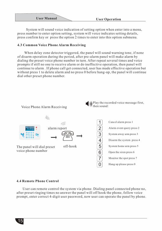
When delay zone detector triggered, the panel will sound warning tone, if none of disarm operation during the period, after pre-alarm panel will make alarm by dialing the preset voice phone number in turn. After repeat several times and voice prompts if still no one to receive alarm or do ineffective operation, then panel will continue to alarm . If phone call get connected, user has made effective operation butwithout press 1 to delete alarm and no press 0 before hang-up, the panel will continuedial other preset phone number.
Voice Phone Alarm Receiving
alarm report
off-hookThe panel will dial preset voice phone number
Play the recorded voice message first, then sound:
Cancel alarm press 1
Alarm event query press 2
System away arm press 3
Disarm the system press 4
System home arm press 5
Open the siren press 6
Monitor the spot press 7
Hang up please press 0
4.4 Remote Phone Control
User can remote control the system via phone. Dialing panel connected phone no,after preset ringing times no answer the panel will off hook the phone, follow voice prompt, enter correct 4-digit user password, now user can operate the panel by phone.
M DY
1 2 3
4
7
5
8
0
6
9
SOSRFID
+
-
#
M DY
1 2 3
4
7
5
8
0
6
9
SOSRFID
+
-
#
M DY
1 2 3
4
7
5
8
0
6
9
SOSRFID
+
-
#
M DY
1 2 3
4
7
5
8
0
6
9
SOSRFID
+
-
#
M DY
1 2 3
4
7
5
8
0
6
9
SOSRFID
+
-
#
M DY
1 2 3
4
7
5
8
0
6
9
SOSRFID
+
-
#
User Manual
Panel
16
1
2
3
4
X X X X
0
M DY
1 2 3
4
7
5
8
0
6
9
SOSRFID
+
-
User Operation
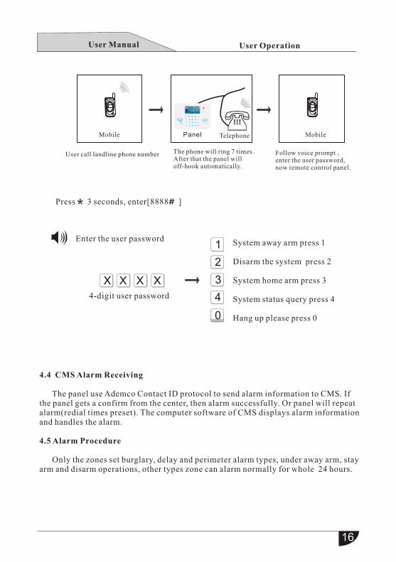
MobileMobile Telephone
User call landline phone number The phone will ring 7 times.After that the panel will off-hook automatically.
Follow voice prompt ,enter the user password,now remote control panel.
Press 3 seconds, enter[8888 ]
Enter the user password
4-digit user password
System away arm press 1
Disarm the system press 2
System home arm press 3
System status query press 4
Hang up please press 0
4.4 CMS Alarm Receiving
The panel use Ademco Contact ID protocol to send alarm information to CMS. If the panel gets a confirm from the center, then alarm successfully. Or panel will repeat alarm(redial times preset). The computer software of CMS displays alarm informationand handles the alarm.
4.5 Alarm Procedure
Only the zones set burglary, delay and perimeter alarm types, under away arm, stayarm and disarm operations, other types zone can alarm normally for whole 24 hours.
* #
User Manual
17
wired
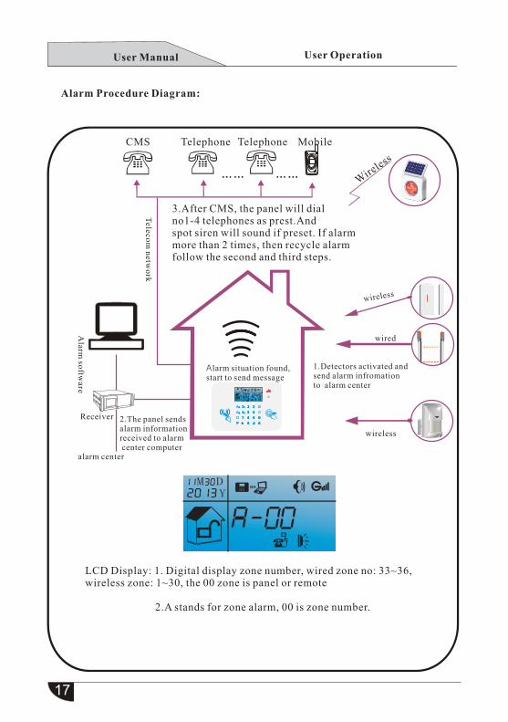
2.A stands for zone alarm, 00 is zone number.
M DY
User Operation
Alarm Procedure Diagram:
CMS Telephone Telephone Mobile
3.After CMS, the panel will dial no1-4 telephones as prest.And spot siren will sound if preset. If alarmmore than 2 times, then recycle alarm follow the second and third steps.
wireless
Teleco
m n
etwo
rk
Alarm
softw
are
Alarm situation found,start to send message
1.Detectors activated andsend alarm infromation to alarm center
alarm center
Receiver 2.The panel sends alarm informationreceived to alarm center computer
wireless
LCD Display: 1. Digital display zone number, wired zone no: 33~36,wireless zone: 1~30, the 00 zone is panel or remote
Wire
less
M DY
1 2 3
4
7
5
8
0
6
9
SOSRFID
+
-
#
M DY
1 2 3
4
7
5
8
0
6
9
SOSRFID
+
-
#
M DY
1 2 3
4
7
5
8
0
6
9
SOSRFID
+
-
#
M DY
1 2 3
4
7
5
8
0
6
9
SOSRFID
+
-
#
M DY
1 2 3
4
7
5
8
0
6
9
SOSRFID
+
-
#
M DY
1 2 3
4
7
5
8
0
6
9
SOSRFID
+
-
#
User Manual
M DY
18
User Operation
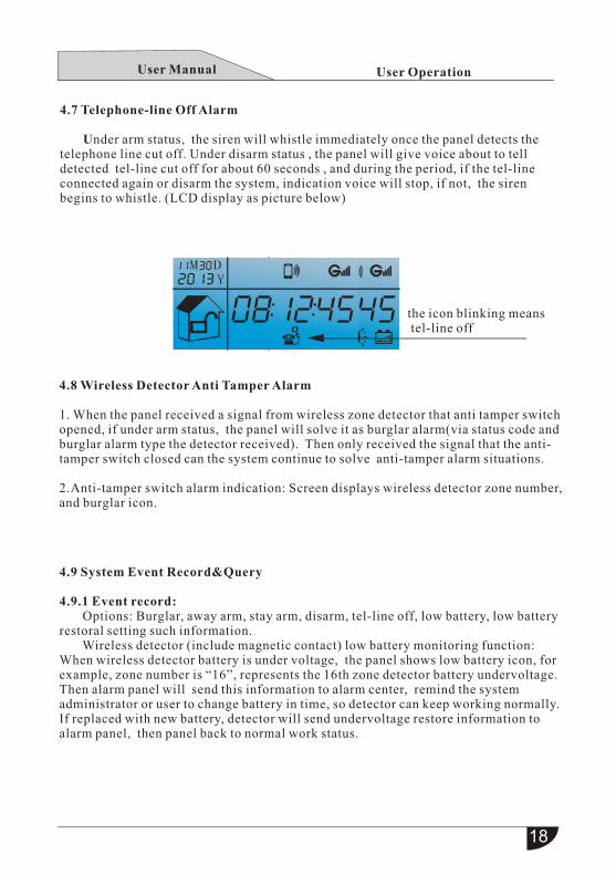
4.7 Telephone-line Off Alarm
Under arm status, the siren will whistle immediately once the panel detects the telephone line cut off. Under disarm status , the panel will give voice about to tell detected tel-line cut off for about 60 seconds , and during the period, if the tel-line connected again or disarm the system, indication voice will stop, if not, the siren begins to whistle. (LCD display as picture below)
4.8 Wireless Detector Anti Tamper Alarm
1. When the panel received a signal from wireless zone detector that anti tamper switch opened, if under arm status, the panel will solve it as burglar alarm(via status code and burglar alarm type the detector received). Then only received the signal that the anti- tamper switch closed can the system continue to solve anti-tamper alarm situations.
2.Anti-tamper switch alarm indication: Screen displays wireless detector zone number, and burglar icon.
4.9 System Event Record&Query
4.9.1 Event record: Options: Burglar, away arm, stay arm, disarm, tel-line off, low battery, low battery restoral setting such information. Wireless detector (include magnetic contact) low battery monitoring function: When wireless detector battery is under voltage, the panel shows low battery icon, for example, zone number is “16”, represents the 16th zone detector battery undervoltage. Then alarm panel will send this information to alarm center, remind the system administrator or user to change battery in time, so detector can keep working normally.If replaced with new battery, detector will send undervoltage restore information to alarm panel, then panel back to normal work status.
the icon blinking means tel-line off
User Manual
19
When the AC power off, Fault Indicator blinking, if still no restoration after AC
power off delay setting, then AC loss reported to alarm center, and dial user’s phone,
after AC power restored about 1 minute, alarm center receiver will receive signal of
AC supply again .
User Operation
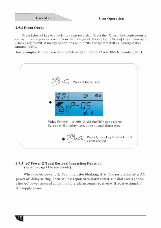
4.9.2 Event Query
Press [Query] key to check the event recorded. Press the [Query] key continuouslycan acquire the previous records in chronological. Press [Up], [Down] keys to navigate, [Back] key to exit, if no any operations within 20s, the system will exit query status automatically.
For example: Burglar alarm at the 5th wired zone at 0:12 AM 30th November, 2013
Press “Query”key
Voice Prompt: At 00:12 AM the fifth zone alarm.Screen will display date, zone no and alarm type.
Press Query key to check next event record
4.9.3 AC Power Off and Restoral Inspection Function (Refer to page41 to see details)
User Manual
20
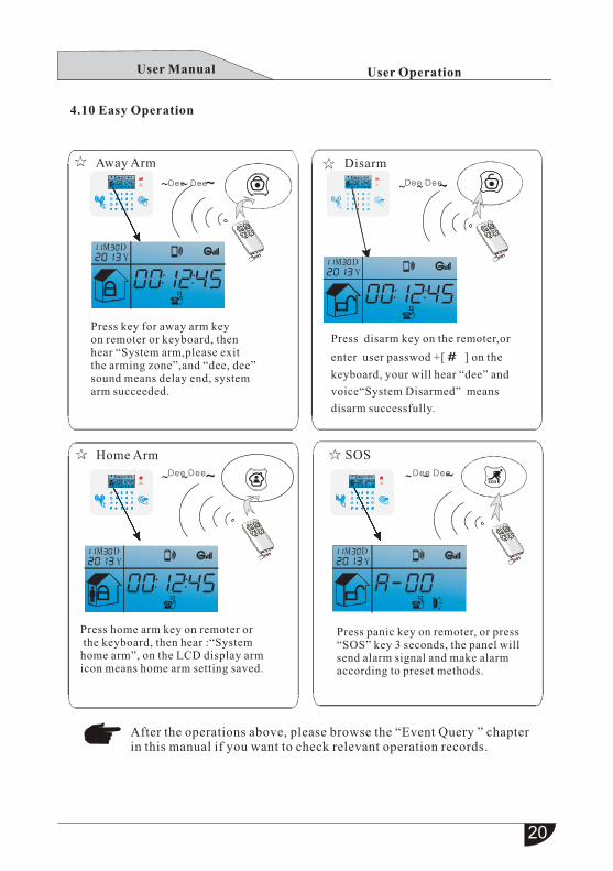
Press disarm key on the remoter,or
enter user passwod +[ ] on the
keyboard, your will hear “dee” and
voice“System Disarmed” means
disarm successfully.
M
M M
MD
D D
DY
Y Y
Y
1
1 1
12
2 2
23
3 3
3
4
4 4
4
7
7 7
7
5
5 5
5
8
8 8
8
0
0 0
0
6
6 6
6
9
9 9
9
SOS
SOS SOS
SOSRFID
RFIDRFID
RFID
+
+ +
+
-
- -
-
User Operation
4.10 Easy Operation
Away Arm Disarm
Dee Dee Dee Dee
Press key for away arm key on remoter or keyboard, thenhear “System ,please arm exit the zone arming ”,and “dee, dee” sound means delay end, system arm succeeded.
Home Arm SOS
Dee Dee Dee Dee
Press home arm key on remoter or the keyboard, then hear :“System home arm”, on the LCD display arm icon means home arm setting saved.
Press panic key on remoter, or press“SOS” key 3 seconds, the panel will send alarm signal and make alarm according to preset methods.
After the operations above, please browse the “Event Query ” chapter in this manual if you want to check relevant operation records.
#
# #
#
M
M M
MD
D D
DY
Y Y
Y
1
1 1
12
2 2
23
3 3
3
4
4 4
4
7
7 7
7
5
5 5
5
8
8 8
8
0
0 0
0
6
6 6
6
9
9 9
9
SOS
SOS SOS
SOSRFID
RFIDRFID
RFID
+
+ +
+
-
- -
-
#
# #
#
M
M M
MD
D D
DY
Y Y
Y
1
1 1
12
2 2
23
3 3
3
4
4 4
4
7
7 7
7
5
5 5
5
8
8 8
8
0
0 0
0
6
6 6
6
9
9 9
9
SOS
SOS SOS
SOSRFID
RFIDRFID
RFID
+
+ +
+
-
- -
-
#
# #
#
M
M M
D
D D
Y
Y Y
1
1 1
2
2 2
3
3 3
4
4 4
7
7 7
5
5 5
8
8 8
0
0 0
6
6 6
9
9 9
SOS
SOS SOS
RFID
RFIDRFID
+
+ +
-
- -
#
# #
M
M M
D
D D
Y
Y Y
1
1 1
2
2 2
3
3 3
4
4 4
7
7 7
5
5 5
8
8 8
0
0 0
6
6 6
9
9 9
SOS
SOS SOS
RFID
RFIDRFID
+
+ +
-
- -
#
# #
M
M M
D
D D
Y
Y Y
1
1 1
2
2 2
3
3 3
4
4 4
7
7 7
5
5 5
8
8 8
0
0 0
6
6 6
9
9 9
SOS
SOS SOS
RFID
RFIDRFID
+
+ +
-
- -
#
# #
User Manual
4.11 RFID Card SMS Editing(Please refer to page11in this manual)
4.12 Alarm Panel GSM Phone Call Fucntion(Please refer to page11in this manual)
4.13 Mobile APP Function(Please refer to page22~23in this manual)
4.11 GSM SMS Operation (Please refer to page10~11in this manual)
User OperationUser Manual
APP Software
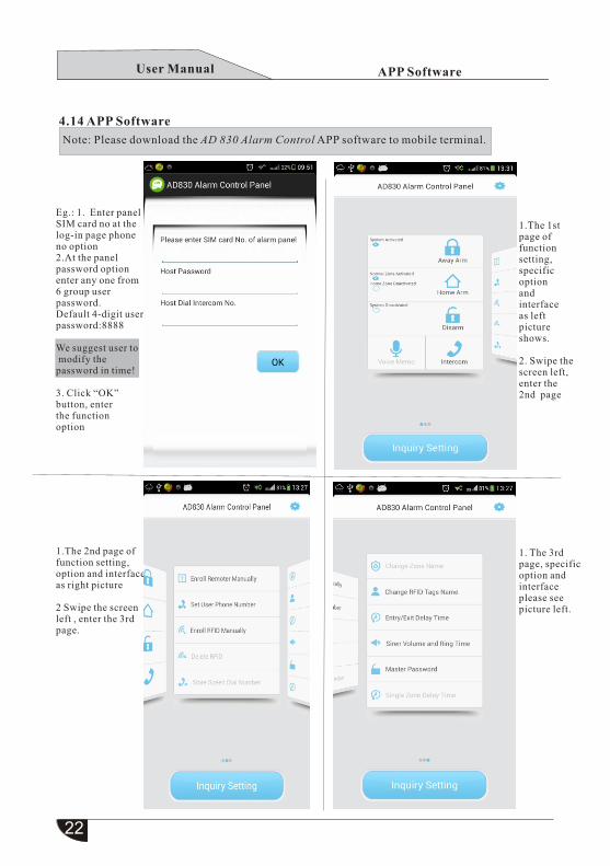
4.14 APP Software
Note: Please download the AD 830 Alarm Control APP software to mobile terminal.
Eg.: 1. Enter panel SIM card no at the log-in page phone no option2.At the panelpassword option enter any one from6 group user password.Default 4-digit user password:8888
We suggest user to modify the password in time!
3. Click “OK” button, enter the functionoption
1.The 2nd page offunction setting, option and interface as right picture
2 Swipe the screenleft , enter the 3rd page.
1.The 1st page of function setting,specific optionandinterface as left picture shows.
2. Swipe thescreen left, enter the 2nd page
1. The 3rd page, specificoption and interface please see picture left.
User Manual
APP Software
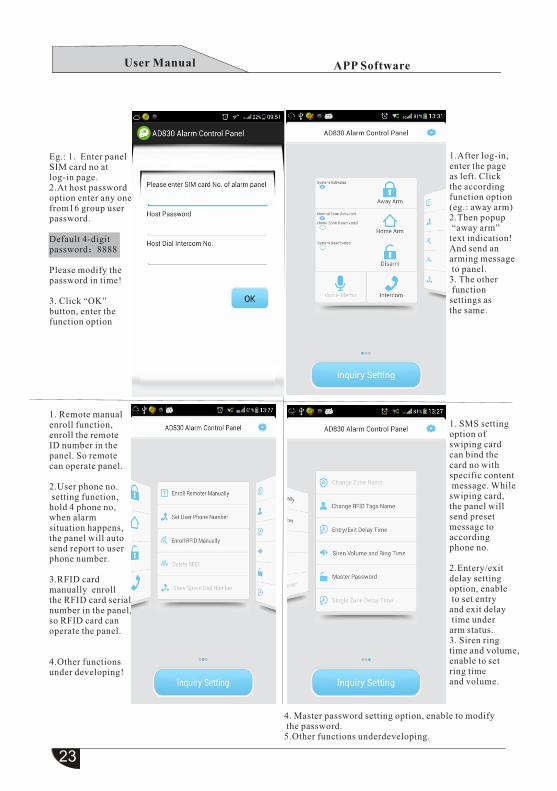
Eg.: 1. Enter panelSIM card no at log-in page.2.At host password option enter any onefrom16 group user password.
Default 4-digitpassword:8888
Please modify thepassword in time!
3. Click “OK” button, enter the function option
1. Remote manual enroll function, enroll the remoteID number in the panel. So remote can operate panel.
2.User phone no. setting function, hold 4 phone no, when alarmsituation happens,the panel will autosend report to user phone number.
3.RFID card manually enrollthe RFID card serial number in the panel, so RFID card can operate the panel.
4.Other functionsunder developing!
1.After log-in, enter the pageas left. Click the according function option(eg.: away arm)2.Then popup “away arm” text indication! And send an arming message to panel.3. The other function settings as the same.
1. SMS setting option of swiping card can bind thecard no with specific content message. Whileswiping card, the panel will send preset message to according phone no.
2.Entery/exit delay setting option, enable to set entry and exit delay time under arm status.3. Siren ringtime and volume,enable to set ring timeand volume.
4. Master password setting option, enable to modify the password. 5.Other functions underdeveloping.
User Manual
3 Set User Phone Number
1 Clock Setting
2 Set User Password
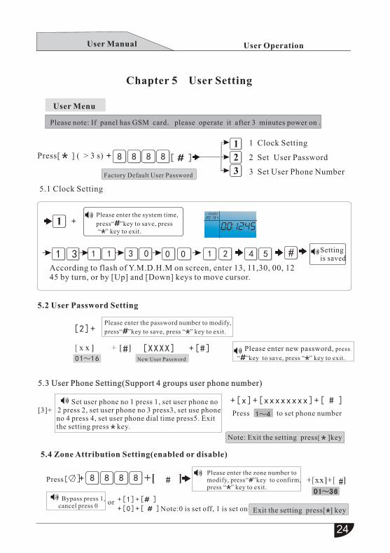
Please enter the password number to modify, press“ ”key to save, press “ ” key to exit.
Please enter new password, press
“ ”key to save, press “ ” key to exit.
1 3
8
8
8
8
8
8
8
8
Factory Default User Password
11 3 0 21 0 0 4 5
01~16
1~4
New User Password
[XXXX] +[#]
[2]+
Set user phone no 1 press 1, set user phone no [3]+ 2 press 2, set user phone no 3 press3, set use phone no 4 press 4, set user phone dial time press5. Exit the setting press key.
+
Note: Exit the setting press[ ]key
Exit the setting press[ ] key
Press[ ]
+[0]+[ ]Note:0 is set off, 1 is set on +[1]+[ ]
Press to set phone number
User Operation
Chapter 5 User Setting
User Menu
Press[ ] ( > 3 s) [ ]
5.1 Clock Setting
Please enter the system time,
press“ ”key to save, press “ ” key to exit.
Setting is saved
According to flash of Y.M.D.H.M on screen, enter 13, 11,30, 00, 1245 by turn, or by [Up] and [Down] keys to move cursor.
5.2 User Password Setting
+[x]+[xxxxxxxx]+[ # ]
5.4 Zone Attribution Setting(enabled or disable)
5.3 User Phone Setting(Support 4 groups user phone number)
Bypass press 1,cancel press 0
or
M DY
M DY
M DY
#
# # Please enter the zone number tomodify, press“ ”key to confirm, press “ ” key to exit.
Please note: If panel has GSM card, please operate it after 3 minutes power on .
User Manual
Set system on the keyboard, press to save, press to exit setting.
System Setting
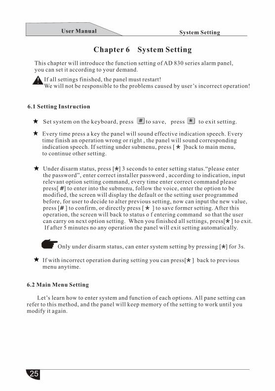
Chapter 6 System Setting
This chapter will introduce the function setting of AD 830 series alarm panel,you can set it according to your demand.
If all settings finished, the panel must restart!We will not be responsible to the problems caused by user’s incorrect operation!
6.1 Setting Instruction
Every time press a key the panel will sound effective indication speech. Every time finish an operation wrong or right , the panel will sound corresponding indication speech. If setting under submenu, press [ ]back to main menu, to continue other setting.
Under disarm status, press [ ] 3 seconds to enter setting status.“please enter the password”, enter correct installer password , according to indication, inputrelevant option setting command, every time enter correct command please press[ ] to enter into the submenu, follow the voice, enter the option to be modified, the screen will display the default or the setting user programmed before, for user to decide to alter previous setting, now can input the new value,press [ ] to confirm, or directly press [ ] to save former setting. After thisoperation, the screen will back to status o f entering command so that the user can carry on next option setting. When you finished all settings, press[ ] to exit. If after 5 minutes no any operation the panel will exit setting automatically.
Only under disarm status, can enter system setting by pressing [ ] for 3s.
If with incorrect operation during setting you can press[ ] back to previous menu anytime.
6.2 Main Menu Setting
Let’s learn how to enter system and function of each options. All pane setting can refer to this method, and the panel will keep memory of the setting to work until youmodify it again.
User Manual
8
9
7321
1
2
4
3
5
6
7
1
XX
M M M M
2
Set user password press one
MM M M M M
Setting is saved
Setting is saved
8 9
Password setting
CMS setting
User phone setting
System option setting Enroll wireless device
Zone setting
System manitenance
Other setting
High-level setting
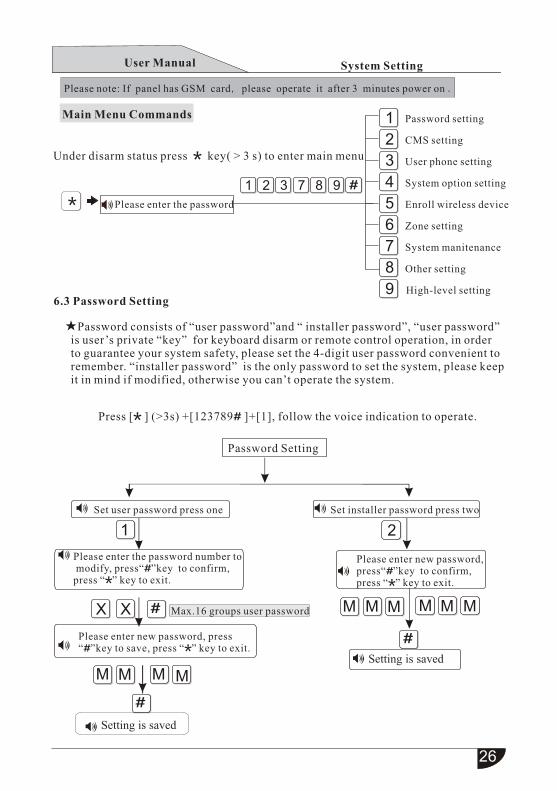
Please enter the password number to modify, press“ ”key to confirm, press “ ” key to exit.
Please enter new password, press“ ”key to confirm,
press “ ” key to exit.
Set installer password press two
Max.16 groups user password
Under disarm status press key( > 3 s) to enter main menu
System Setting
Main Menu Commands
Please enter the password
6.3 Password Setting
Password consists of “user password”and “ installer password”, “user password” is user’s private “key” for keyboard disarm or remote control operation, in order to guarantee your system safety, please set the 4-digit user password convenient toremember. “installer password” is the only password to set the system, please keepit in mind if modified, otherwise you can’t operate the system.
Password Setting
Please enter new password, press“ ”key to save, press “ ” key to exit.
Press [ ] (>3s) +[123789 ]+[1], follow the voice indication to operate.
Please note: If panel has GSM card, please operate it after 3 minutes power on .
User Manual
1 2 3 7 8 9 21
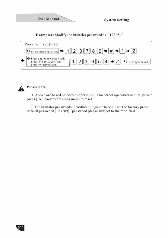
1 2 3 6 5 4Please enter new password,
press“ ”key to confirm, press “ ” key to exit.
Example1: Modify the installer password as“123654”
System Setting
Press key (> 3s)
Please enter the password
Setting is saved
Please note:
1. Above are based on correct operation, if incorrect operation occurs, pleasepress [ ] back to previous menu to reset.
2. The installer passwords introduced to guide here all are the factory preset default password [123789], password please subject to the modified.
User Manual
#
X X X X
1 2 3 4 5
1
X
2 3 4
X X X X X
5
Set CMS phone
No 1 press 1
Set CMS phone
No 2 press 2
Please enter the phone no,
press delete key to clear,
pause key delay 1s to dial
out, press “ ” to save,
press “ ” to exit.
Please enter the user
number, press“ ”
to save, press “ ”
to exit.
Set CMS user
number press 3
Set CMS
communication
test time press 4
Set CMS dialing
time press 5
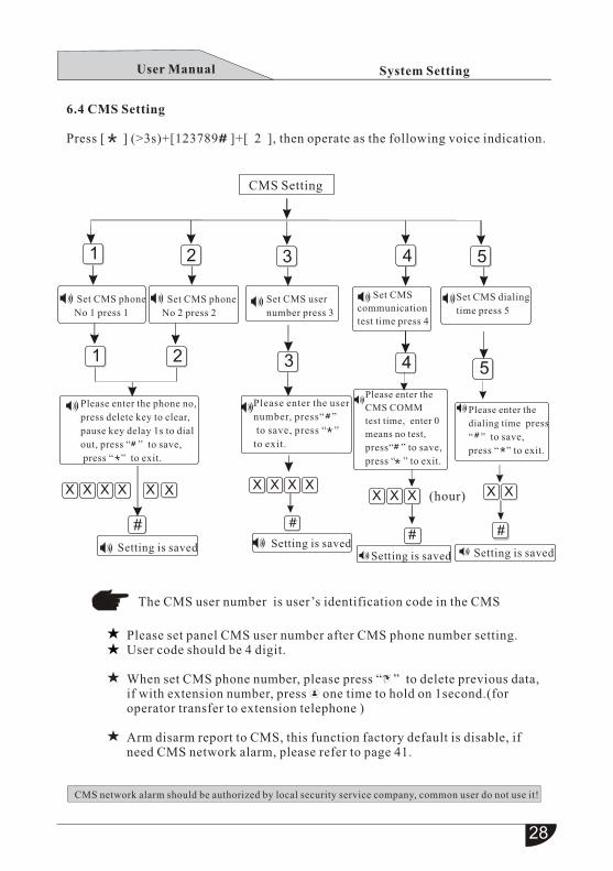
CMS network alarm should be authorized by local security service company, common user do not use it!
CMS Setting
System Setting
6.4 CMS Setting
Press [ ] (>3s)+[123789 ]+[ 2 ], then operate as the following voice indication.
Setting is saved Setting is saved
The CMS user number is user’s identification code in the CMS
Please set panel CMS user number after CMS phone number setting.User code should be 4 digit.
When set CMS phone number, please press “ ” to delete previous data,if with extension number, press one time to hold on 1second.(for operator transfer to extension telephone )
Arm disarm report to CMS, this function factory default is disable, ifneed CMS network alarm, please refer to page 41.
Please enter the
CMS COMM
test time, enter 0
means no test,
press“ ” to save,
press “ ” to exit.
Please enter the
dialing time press
“ ” to save,
press “ ” to exit.
(hour)
Setting is saved Setting is saved
User Manual
1 2 3 4 5
0 5
1 2 3 37 98
7 6 5 4 3 2 01
1
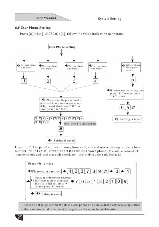
6.5 User Phone Setting
Set user phone No1 press 1
Set use phone No2 press 2
Set use phone No3 press 3
Set use phone No4 press 4
Set user phone dialing time press 5
Please enter the dialing time press “ ” to save, press “ ” to exit.
Setting is saved
Setting is saved
Please enter the phone number, press delete key to clear, pause key delay 1s to dial out, press “ ” tosave, press “ ” to exit.
X
X
X
X
XXX
X
XXX
X
X XX X X
Please do not set government public alarm phone no as individual alarm receiving station,
otherwise, users take charge of all negative effects and legal obligation.
Note: Max 17 digits number
System Setting
Press [ ] >3s+[123789 ]+[3], follow the voice indication to operate.
User Phone Setting
Example 2: The panel connect to one phone call, voice alarm receiving phone is local number: “76543210”, if want to set it as the No1 voice phone:(Pls note: non-local tel number should add local area code ahead, non-local mobile phone add 0 ahead.)
Press ( >3s)
Please enter password
Please enter the phone no, pressdelete key to clear, pause key delay 1s to dial out, press “ ” to save, press “ ” to exit.
Setting is saved
User Manual
Clock setting Entry delay setting
Exit delay setting
Set remote arm/disarm tone
Set siren time
Set phone off-hook ringing time
TEL-line off detection setting
AC loss inspection time setting
Zone faulted arming setting
8
92 81 73
1
2
4
3
5
6
7
1
2
3
4
6
4
9 9
7321 8 9 4 1
1 3 1 1 3 0 0 0 1 2
Please enter the systemtime, press to save, press to exit
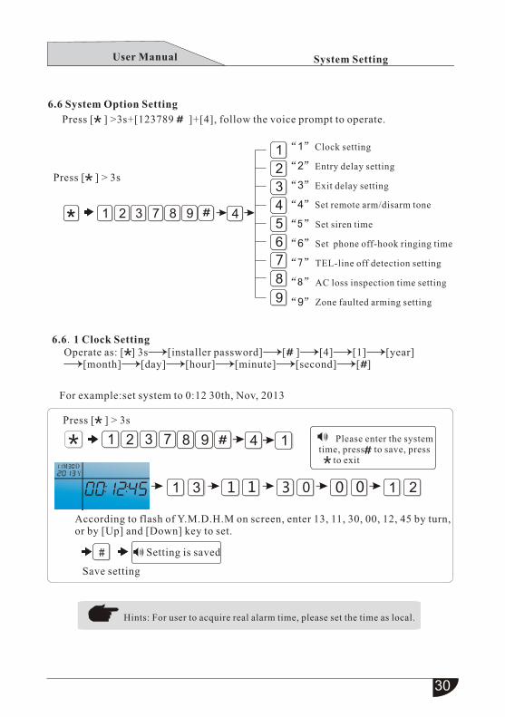
6.6 System Option Setting
6.6.1 Clock Setting
For example:set system to 0:12 30th, Nov, 2013
System Setting
Press [ ] >3s+[123789 ]+[4], follow the voice prompt to operate.
Press [ ] > 3s
Operate as: [ ] 3s [ password] [ ] [4] [1] [year] installer [second] [month] [day] [hour] [minute] [ ]
Press [ ] > 3s
According to flash of Y.M.D.H.M on screen, enter 13, 11, 30, 00, 12, 45 by turn,or by [Up] and [Down] key to set.
Setting is saved
Save setting
Hints: For user to acquire real alarm time, please set the time as local.
M DY
M DY
M DY
#
User Manual
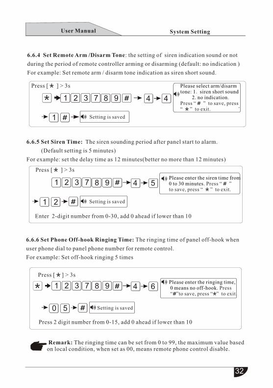
6.6.4 Set Remote Arm /Disarm Tone: the setting of siren indication sound or not
during the period of remote controller arming or disarming (default: no indication )
For example: Set remote arm / disarm tone indication as siren short sound.
6.6.5 Set Siren Time: The siren sounding period after panel start to alarm.
(Default setting is 5 minutes)
For example: set the delay time as 12 minutes(better no more than 12 minutes)
6.6.6 Set Phone Off-hook Ringing Time: The ringing time of panel off-hook when
user phone dial to panel phone number for remote control.
For example: Set off-hook ringing 5 times
4 4
Please enter the siren time from 0 to 30 minutes. Press “ ”to save, press “ ” to exit.
Please enter the ringing time, 0 means no off-hook. Press “ ”to save, press “ ” to exit.
1
1
2
0 5
Please select arm/disarm tone: 1. siren short sound 2. no indication.Press “ ” to save, press “ ” to exit.
97321 8
7321 8 9 4 5
7321 8 9 4 6
System Setting
Press [ ] > 3s
Setting is saved
Press [ ] > 3s
Setting is saved
Enter 2-digit number from 0-30, add 0 ahead if lower than 10
Press [ ] > 3s
Setting is saved
Press 2 digit number from 0-15, add 0 ahead if lower than 10
Remark: The ringing time can be set from 0 to 99, the maximum value based on local condition, when set as 00, means remote phone control disable.
.
User Manual
7321 8 9
9
4
4
2
3
0
0
5
0
7321 8
0
3
Please enter the entry delay time, press to save,
press key to exit.
Please enter password
Please enter the exit delay time, press to save,
press key to exit.
System Setting
Press [ ] > 3s
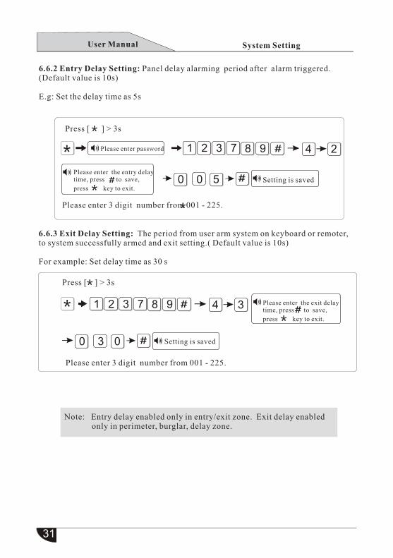
6.6.2 Entry Delay Setting: Panel delay alarming period after alarm triggered.(Default value is 10s)
E.g: Set the delay time as 5s
Setting is saved
Please enter 3 digit number from 001 - 225.
6.6.3 Exit Delay Setting: The period from user arm system on keyboard or remoter,to system successfully armed and exit setting.( Default value is 10s)
For example: Set delay time as 30 s
Press [ ] > 3s
Setting is saved
Please enter 3 digit number from 001 - 225.
Note: Entry delay enabled only in entry/exit zone. Exit delay enabled only in perimeter, burglar, delay zone.
User Manual
1
0
1
5 0
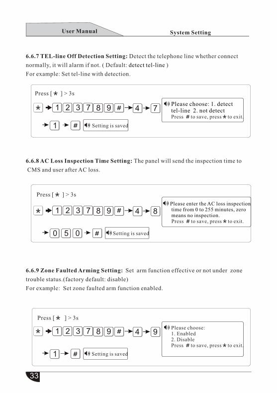
6.6.7 TEL-line Off Detection Setting: Detect the telephone line whether connect
normally, it will alarm if not. ( Default: ) detect tel-line
For example: Set tel-line with detection.
6.6.8 AC Loss Inspection Time Setting: The panel will send the inspection time to
CMS and user after AC loss.
6.6.9 Zone Faulted Arming Setting: Set arm function effective or not under zone
trouble status.(factory default: disable)
For example: Set zone faulted arm function enabled.
7
7
7
3
3
3
2
2
2
1
1
1
8
8
8
9
9
9
4
4
4
7
8
9
Please choose: 1. detect tel-line 2. not detectPress to save, press to exit.
Please choose:1. Enabled2. Disable
. Press to save, press to exit
Please enter the AC loss inspection time from 0 to 255 minutes, zero means no inspection. . Press to save, press to exit
Press [ ] > 3s
Setting is saved
Press [ ] > 3s
Setting is saved
Press [ ] > 3s
Setting is saved
System SettingUser Manual
7
7
3
3
2
2
1
1
5
5 1 2
8
8
9
9
1.Remote controller code study
1.Detector code study
1.wireless siren code study
1.RFID card code study
2.Enter remote controller code
2.Enter Detector code
2.wireless siren code delete
2.RFID card code delete
3.Remote controller code delete
3.Detector code delete
Enroll Remote controller
Enroll Detector
Enroll Wireless siren
Enroll RFID card
Please enter the remotenumber. Press “ ” keyto confirm, press “ ” key to exit.
Please enter the remote no.
Press “ ” to confirm, press
“ ” to exit.Please enter the remote
code. Press “ ” to
confirm, press “ ” to exit.
3
7
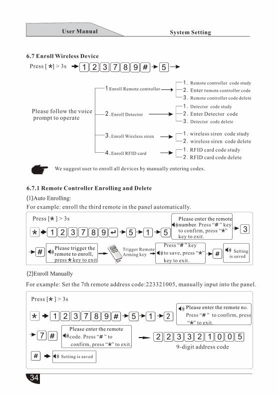
(1) Auto Enrolling:
(2)Enroll Manually
3 0322 2 01 5
Please trigger theremote to enroll,press key to exit
Setting is saved
7321 5 1 58 9
Trigger RemoteArming key
Press “ ” key
to save, press “ ”
key to exit.
For example: enroll the third remote in the panel automatically.
For example: Set the 7th remote address code:223321005, manually input into the panel.
9-digit address code
6.7 Enroll Wireless Device
1.
2.
3.
4.
System Setting
Press [ ] > 3s
Please follow the voice prompt to operate
We suggest user to enroll all devices by manually entering codes.
6.7.1 Remote Controller Enrolling and Delete
Press [ ] > 3s
Press [ ] > 3s
Setting is saved
User Manual
1
1
2
5
(1)A uto enrolling
(2) Manually enrolling
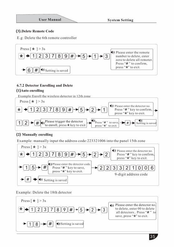
(3). Delete Remote Code
6.7.2 Detector Enrolling and Delete
1 8
7
7
7
3
3
3
2
2
2
1
1
1
8
8
8
9
9
9
5
5
5
1
2
2
3
1
2
Please enter the remote number to delete, enter zero to delete all remoter.Press “ ” to confirm, press “ ” to exit.
Please enter the detector no. Press “ ” key to confirm,press “ ” key to exit.
Please enter the detector no. Press “ ” key to confirm,press “ ” key to exit.
Please enter the detector no.to delete, enter 00 to delete all detectors.. Press “ ” to save, press “ ” to exit.
Please enter the detector code. Press “ ” key to save,press “ ” key to exit.
Please trigger the detector to enroll, press key to exit
6
7321 8 9 5 2 3
E.g: Delete the 6th remote controller
Example: manually input the address code:223321006 into the panel 15th zone
3 0322 2 01 69-digit address code
System Setting
Press [ ] > 3s
Setting is saved
Setting is saved
Example: Delete the 18th detector
Example:Enroll the wireless detector in 12th zone
Press [ ] > 3s
Setting is saved
Press [ ] > 3s
Press [ ] > 3s
Setting is saved
Press “ ” to save,press “ ” to exit.
35
User Manual
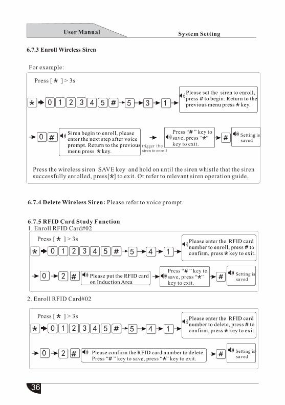
6.7.3 Enroll W ireless Siren
3
3
3
2
2
2
1
1
1
2
2
0
0
0
4
4
4
5
5
5
5
5
5
3
4
4
1
1
1
0
0
0
Please set the siren to enroll,press to begin. Return to theprevious menu press key.
Please enter the RFID card number to enroll, press to confirm, press key to exit.
Please enter the RFID card number to delete, press to confirm, press key to exit.
Siren begin to enroll, please enter the next step after voiceprompt. Return to the previousmenu press key.
Please put the RFID card on Induction Area
Please confirm the RFID card number to delete.Press “ ” key to save, press “ ” key to exit.
Setting is saved
Setting is saved
Setting is saved
trigger the siren to enroll
Press “ ” key to save, press “ ” key to exit.
Press “ ” key to save, press “ ” key to exit.
System Setting
For example:
Press [ ] > 3s
Press [ ] > 3s
Press [ ] > 3s
Press the wireless siren SAVE key and hold on until the siren whistle that the siren successfully enrolled, press[ ] to exit. Or refer to relevant siren operation guide.
6.7.5 RFID Card Study Function1. Enroll RFID Card#02
6.7.4 Delete Wireless Siren: Please refer to voice prompt.
2. Enroll RFID Card#02
.
User Manual

1 2 3 4
X XX X
0 1 2 3 4 5 6
Please select zone type: 0. Disable 1. delay zone 2.perimeterzone 3. Indoor (burglar) zone 4.SOSzone. 5. 24-hour zone. 6. fire zone.
. Press to save, press to exit
Please select siren type:1.pedal point2.pulse tone3.mute
Please select siren type:1.pedal point2.pulse tone 3.mute Press to save, press to exit.
Ind
oo
r Zo
ne
Fire Z
on
e
24
-ho
ur zo
ne
Note: 00 is only used as the SOS key on thepanel or remote
System Setting
6.8 Zone Attribution Setting
Press [ ] >3s+[123789 ]+[6], follow the voice prompt to operate.
Zone Attribution Setting
Set sos siren type press 3
Set zone door contact opendetection press4
Please choose:1.Detect2. Not detectPress to save, press to exit.
Setting is saved
Setting is savedSetting is saved
SO
S Z
on
e
Perim
eter Zo
ne
Delay Z
on
e
Disab
le
Setting is saved
Indoor(Burglar) Zone: Enabled only at system away arming status.Delay, Perimeter Zone: Enabled only at system away arming or stay arming status.
Set zone attribution press 1
Please enter the zone no. to modify. Press to confirm, press to exit.
Set zone siren type press 2
Please enter the zone no to modify. Press to confirm, press to exit.
User Manual
42 31 5
Set timing arm/disarm press 1
Record alarming voice message press 2
Play alarming voicemessage press 3
Delete system log press 4
Restore factory setting press 5
Please enter timing arm disarm group number.Press to confirm, press to exit.
Please confirm again! Press to save, press to exit.
Please confirm again!Press to save, press to exit.
Please start to record after ringing
Note: record time is15 s
Please enter timing arm time, 0:0 is invalid. Press to save, press to exit.
Please enter timing disarm time, 0:0 is invalid. . Press to save, press to exit
Setting is saved
Setting is saved Setting is saved
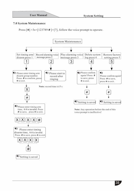
Press [ ] >3s+[123789 ]+[7], follow the voice prompt to operate.
System Setting
7.0 System Maintenance
System Maintenance
Note: Any operation before the end of thisvoice prompt is ineffective!
User Manual
9 7 1321 7 8
System Setting
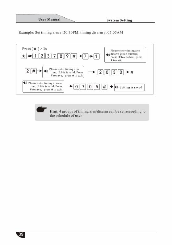
Example: Set timing arm at 20:30PM, timing disarm at 07:05AM
Press [ ] > 3sPlease enter timing arm disarm group number.Press to confirm, press to exit.
Please enter timing arm time, 0:0 is invalid. Press to save, press to exit.
Please enter timing disarm time, 0:0 is invalid. Press to save, press to exit.
Setting is saved
Hint: 4 groups of timing arm/disarm can be set according tothe schedule of user
User Manual
1 2 3
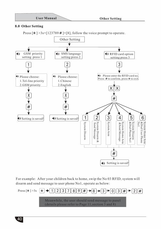
SMS language setting press 2
RFID card option setting press 3
GSM prioritysetting press 1
Setting is saved! Setting is saved!
Setting is saved!
Please choose:
1.Tel-line priority
2.GSM priority
Please choose:
1.Chinese
2.English
Please enter the RFID card no,. Press to confirm, press to exit
Other Setting
1
X X
2 3 4 5 6
Sy
stem D
isarm
Sy
stem D
isarm &
Sen
d Messag
e
Sy
stem A
rm
Sy
stem H
om
e Arm
&
Sen
d Messag
e
Sy
stem D
isarm&
Dial P
ho
ne N
o1
Sy
stem H
om
e Arm
&D
ial User P
ho
ne
No
1
For example: After your children back to home, swip the No 03 RFID, system will
disarm and send message to user phone No1, operate as below:
89 3 0 3 2321 7 8
X X
Other Setting
Press [ ] >3s+[123789 ]+[8], follow the voice prompt to operate.
8.0 Other Setting
Press [ ] >3s
Meanwhile, the user should send message to panel(details please refer to Page 11,section 3 and 8)
User Manual
39
High-level Setting
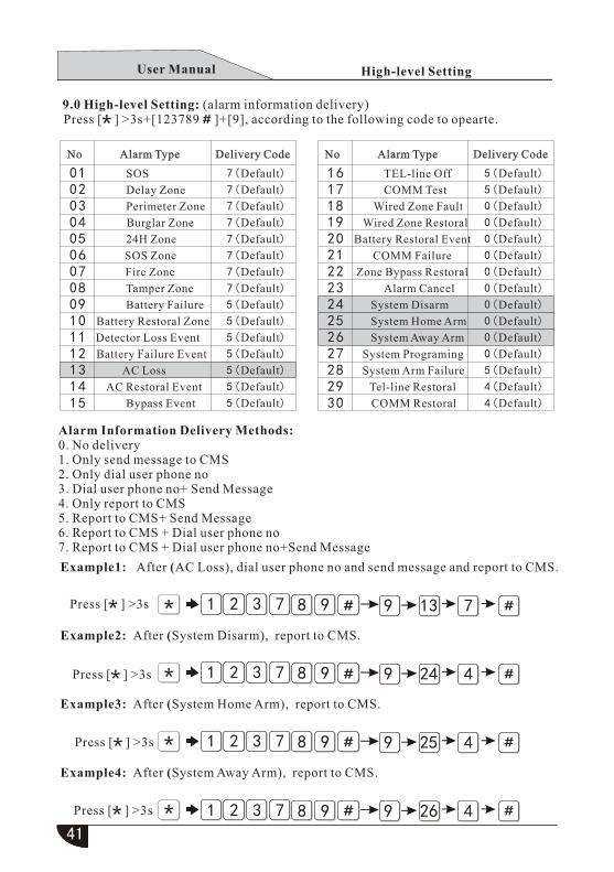
Alarm Information Delivery Methods:0. No delivery1. Only send message to CMS2. Only dial user phone no3. Dial user phone no+ Send Message4. Only report to CMS5. Report to CMS+ Send Message6. Report to CMS + Dial user phone no 7. Report to CMS + Dial user phone no+Send Message
Example1: After (AC Loss), dial user phone no and send message and report to CMS.
Example2: After (System Disarm), report to CMS.
Example3: After (System Home Arm), report to CMS.
Example4: After (System Away Arm), report to CMS.
7
7
7
7
3
3
3
3
2
2
2
2
1
1
1
1
8
8
8
8
9
9
9
9
9
9
9
9
13
24
25
26
7
4
4
4
COMM Test
TEL-line Off 5(Default)
5(Default)
0(Default)
0(Default)
0(Default)
0(Default)
0(Default)
0(Default)
0(Default)
0(Default)
0(Default)
5(Default)
4(Default)
4(Default)
1716
181920212223
252627282930
Wired Zone Fault Wired Zone Restoral
Battery Restoral Event
COMM Failure
Zone Bypass Restoral
Alarm Cancel
System Home Arm
System Away Arm
System Programing
System Arm Failure
Tel-line Restoral
COMM Restoral
0(Default)24 System Disarm
Alarm Type Alarm TypeDelivery Code Delivery CodeNo No
Delay Zone
SOS 7(Default)
7(Default)
7(Default)
7(Default)
7(Default)
7(Default)
7(Default)
7(Default)
5(Default)
5(Default)
5(Default)
5(Default)
5(Default)
5(Default)
5(Default)
0201
03040506070809101112131415
Perimeter Zone
Burglar Zone
24H Zone
SOS Zone
Fire Zone
Tamper Zone
Battery Failure
Battery Restoral Zone
Detector Loss Event
Battery Failure Event
AC Loss
AC Restoral Event
Bypass Event
9.0 High-level Setting: (alarm information delivery)
Press [ ] >3s
Press [ ] >3s
Press [ ] >3s
Press [ ] >3s+[123789 ]+[9], according to the following code to opearte.
Press [ ] >3s
User Manual
Technical Specification
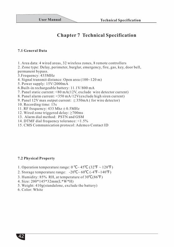
Chapter 7 Technical Specification
7.1 General Data
1. Area data: 4 wired areas, 32 wireless zones, 8 remote controllers2. Zone type: Delay, perimeter, burglar, emergency, fire, gas, key, door bell, permanent bypass.3.Frequency: 433MHz4. Signal transmit distance: Open area (100~120 m)5. Power supply: 15V/2000mA6.Built-in rechargeable battery: 11.1V/800 mA7. Panel static current: <80 mA(12V, exclude wire detector current)8. Panel alarm current: <350 mA/12V(exclude high siren current)9. Panel 12V max output current: ≤ 350mA ( for wire detector) 10. Recording time: 15s11. RF frequency: 433 Mhz 0.5MHz12. Wired zone triggered delay: ≥700ms13. Alarm dial method: PSTN and GSM14. DTMF dial frequency tolerance: <1.5%15. CMS Communication protocol: Ademco Contact ID
7.2 Physical Property
1. Operation temperature range: 0 ℃~ 45℃ (32℉ ~ 120℉)
2. Storage temperature range: -20℃~ 60℃ (-4℉~140℉)
3. Humidity: 85% RH, at temperature of 30℃(86℉)4. Size: 200*145*32mm(L*W*H)5. Weight: 410g(standalone, exclude the battery)6. Color: White
User Manual
42
Maintenance
Chapter 8 Maintenance
8.1 Regular test
The alarm system design on principle of saving customers’ maintenance cost, but westill suggest you to carry out “periodical test” one time every month, to guarantee the system’s working reliability. And please contact the installer immediately if you have found something wrong.
8.2 Cleaning of the control panel machine
After a period of using, the control panel may be oil-stained or dust-covered. Please use soft cotton cloth or sponge to clean it.
Note: Don’t use any lubricant or organic solvent, such as kerosene, acetone and super glue to clean the machine shell, in case to influence the external appearance and the top window transparency.
Chapter 9 Product Limitation
Although the products you bought is high standard, but there still has problems as false alarm or miss alarm, the reasons may be as below:
Lack of Maintenance: The system needs maintenance and test regularly, the detector sensitivity decreasing , may result in false or miss alarm, and the siren disable toto whistle.
Lack of Power Supply: If no power restore or backup power is not enough, the panel can not work normally, it can’t alarm even zone has alarm situation.
Tel-line Trouble: If the telephone line is cut or short-circuit, the panel could not sendout alarm signals.
Limitation of Smoke Detector: Sometimes, because of house design or distance toofar for the smoke detector to receive alarm signal that may cause miss alarm.
System disable to receiving information: If the intruder break in through unprotectedwindow or unknown entrance, or some one knows how to make the alarm devicesdisable to alarm.
In order to guarantee detector and the whole alarm system to work normally, wesuggest user to test it frequently. Even installed our alarm system, user still shouldkeep caution of life and property safety. We will keep on developing new security&protection series product, please pay attention to our product update status, to get our latest technical product and relevant material. Your support is our motivation!
User Manual