Ad Hoc Nets - MAC layer Part II –TDMA and · PDF fileMore MAC Layer protocols •...
55
Ad Hoc Nets - MAC layer Part II – TDMA and Polling
-
Upload
truongxuyen -
Category
Documents
-
view
232 -
download
8
Transcript of Ad Hoc Nets - MAC layer Part II –TDMA and · PDF fileMore MAC Layer protocols •...
Ad Hoc Nets - MAC layer
Part II –TDMA and Polling

More MAC Layer protocols
• Bluetooth Piconet: a polling/TDMA scheme• Cluster TDMA: based on TDMA (with random
access and reserved slots) – research protocol developed at UCLA for the DARPA-WAMIS
project (1994)

Bluetooth:
Where does the name come from?

Bluetooth working group history• February 1998: The Bluetooth SIG is formed
– promoter company group: Ericsson, IBM, Intel, Nokia, Toshiba
• May 1998: Public announcement of the Bluetooth SIG
• July 1999: 1.0A spec (>1,500 pages) is published• December 1999: ver. 1.0B is released• December 1999: The promoter group increases to
9– 3Com, Lucent, Microsoft, Motorola
• March 2001: ver. 1.1 is released• Aug 2001: There are 2,491+ adopter companies
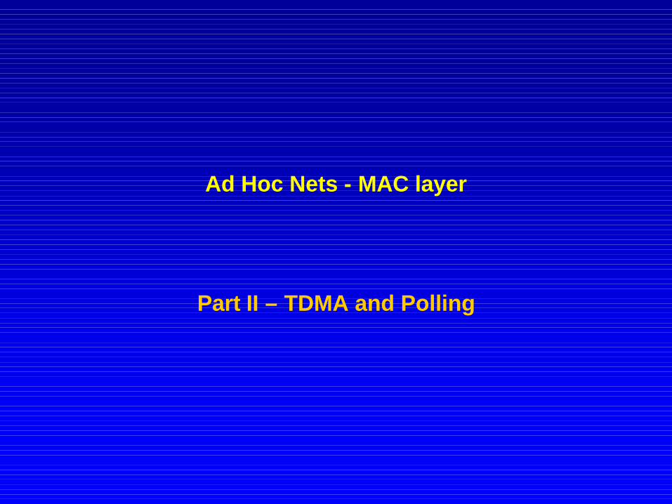
What does Bluetooth do for you?
Synchronization• Automatic synchronization of
calendars, address books, business cards
• Push button synchronization• Proximity operation

Cordless Headset
User benefits• Multiple device access • Cordless phone benefits• Hands free operation
Cordlessheadset

Personal Ad-hoc Networks
Cable Replacement
Landline
Data/Voice Access Points
Putting it all together..
… and combinations!

Example...

Bluetooth Physical link
• Point to point link– master - slave relationship– radios can function as masters or slaves m s
ss
m
s
• Piconet– Master can connect to 7 slaves– Each piconet has max capacity =1 Mbps
– hopping pattern is determined by the master

Connection Setup
• Inquiry - scan protocol– to learn about the clock offset and
device address of other nodes in proximity

Inquiry on time axis
Slave1
Slave2
Master
Inquiry hoppingsequence
f1 f2

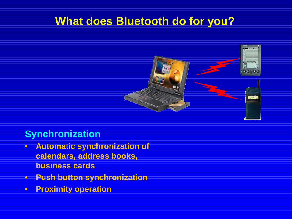
Piconet formation
Master
Active Slave
Parked Slave
Standby
• Page - scan protocol– to establish links with nodes
in proximity

Addressing• Bluetooth device address (BD_ADDR)
– 48 bit IEEE MAC address
• Active Member address (AM_ADDR)– 3 bits active slave address– all zero broadcast address
• Parked Member address (PM_ADDR)– 8 bit parked slave address
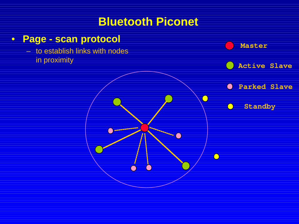
Bluetooth Piconet
Master
Active Slave
Parked Slave
Standby
• Page - scan protocol– to establish links with nodes
in proximity

Piconet MAC protocol : Polling
m
s1
s2
625 λsec
f1 f2 f3 f4
1600 hops/sec
f5 f6
FH/TDD
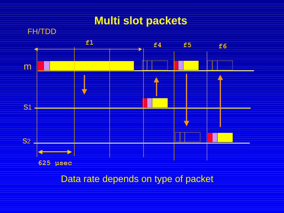
Multi slot packets
m
s1
s2
625 µsec
f1 f4 f5 f6
FH/TDD
Data rate depends on type of packet

Physical Link Types
m
s1
s2
SCO SCO SCO
< Synchronous Connection Oriented (SCO) Link 4 slot reservation at fixed intervals
• Asynchronous Connection-less (ACL) Link– Polling access method
SCO SCO SCOACL ACL ACLACL ACL ACL

Packet Types
Controlpackets
Data/voicepackets
ID*NullPollFHSDM1
Voice data
HV1HV2HV3DV
DM1DM3DM5
DH1DH3DH5

Packet Format
72 bits 54 bits 0 - 2744 bitsAccess code
Header Payload
DataVoice CRC
No CRCNo retries
625 µs
master
slave
header
ARQ
FEC (optional) FEC (optional)

Access Code
• Synchronization• DC offset
compensation• Identification• Signaling
Access code Header Payload
72 bits
Purpose
< Channel Access Code (CAC)< Device Access Code (DAC)< Inquiry Access Code (IAC)
Types
X
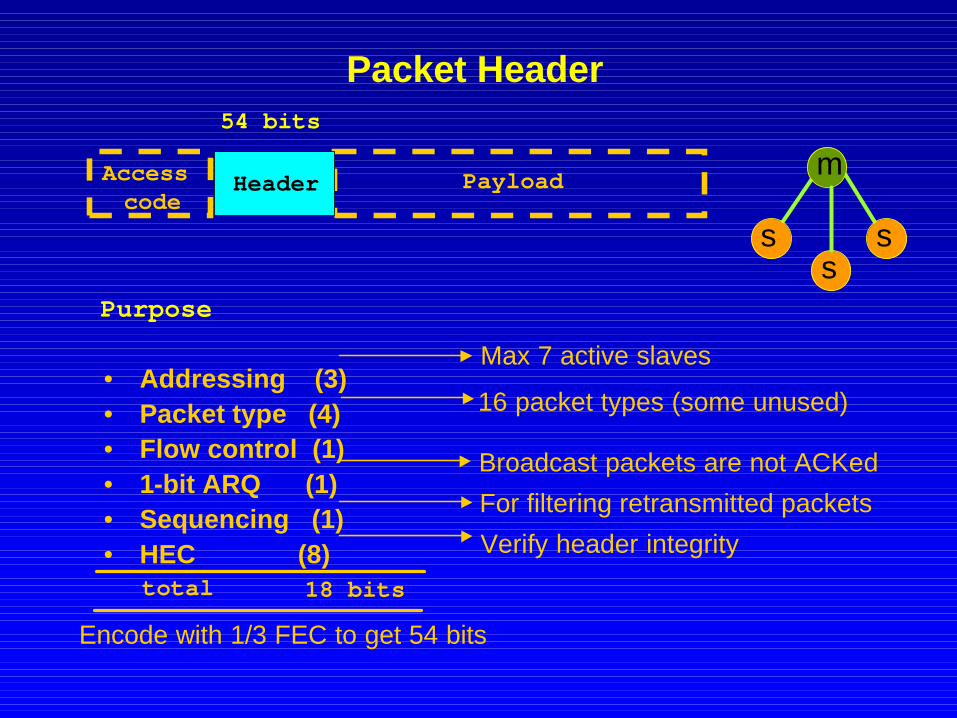
Packet Header
• Addressing (3)• Packet type (4)• Flow control (1)• 1-bit ARQ (1)• Sequencing (1)• HEC (8)
Access code
Header Payload
54 bits
Purpose
Encode with 1/3 FEC to get 54 bits
Broadcast packets are not ACKed
For filtering retransmitted packets
18 bitstotal
ss
m
s
16 packet types (some unused)
Max 7 active slaves
Verify header integrity

Voice Packets (HV1, HV2, HV3)
Access code Header
Payload
72 bits 54 bits 240 bits
30 bytes
= 366 bits
10 bytes
+ 2/3 FEC
+ 1/3 FEC
20 bytes
30 bytesHV3
HV2
HV1
3.75ms (HV3)2.5ms (HV2)
1.25ms (HV1)

Data rate calculation: DM1 and DH1
Payload
Accesscode Header
72 bits 54 bits 240 bits
30 bytes
= 366 bits
2/3 FEC
1 17 2DM1
1 27 2DH1
625 µs
625 µs
1 2
172.827↑172.827↓
108.817↓
108.81600/217↑
RateFreqSizeDir
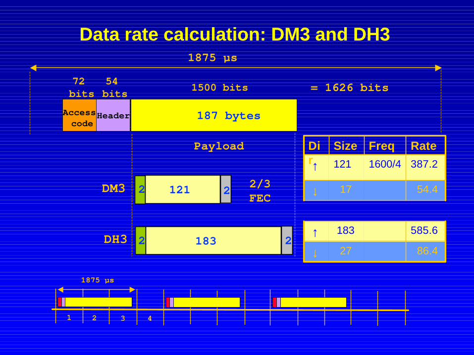
Data rate calculation: DM3 and DH3
Payload
Access code
Header
72 bits
54 bits 1500 bits
187 bytes
= 1626 bits
2/3 FEC
2 121 2DM3
2 183 2DH3
1875 µs
1875 µs
585.6183↑86.427↓
54.417↓
387.21600/4121↑
RateFreqSizeDir
1 2 3 4

Data rate calculation: DM5 and DH5
Payload
AccessCode Header
72 bits
54 bits 2744 bits
343 bytes
= 2870 bits
2/3 FEC
2 224 2DM5
2 339 2DH5
3125 µs
3125 µs 625 µs
1 2 3 4 5 6
723.2339↑57.627↓
36.317↓
477.81600/6224↑
RateFreqSizeDir

Data Packet Types
DM1
DM3
DM5
DH1
DH3
DH5
2/3 FEC
No FEC
Symmetric Asymmetric
36.3477.8 286.7
54.4387.2258.1
108.8108.8108.8
Symmetric Asymmetric
57.6723.2 433.9
86.4585.6390.4
172.8172.8172.8
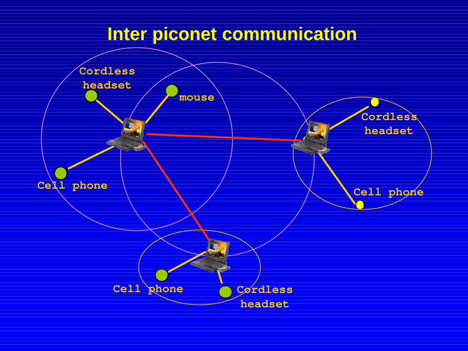
Inter piconet communication
Cell phone Cordlessheadset
Cordlessheadset
Cell phone
Cordlessheadset
Cell phone
mouse

Scatternet

Scatternet, scenario 2
How to schedule presence in two piconets?
Forwarding delay ?
Missed traffic?

Baseband: Summary
• TDD, frequency hopping physical layer• Device inquiry and paging• Two types of links: SCO and ACL links• Multiple packet types (multiple data rates with
and without FEC)
Baseband Baseband
L2CAPL2CAPLMPLMP
Physical
Data link
Device 2Device 1

Link Manager Protocol
Setup and management of Baseband connections
• Piconet Management• Link Configuration• Security
LMP
RFBaseband
AudioLink Manager
L2CAP
Data Con
trolSDP RFCOMM
IP
Applications

Piconet Management• Attach and detach slaves• Master-slave switch• Establishing SCO links• Handling of low power modes ( Sniff, Hold, Park)
req
response
Paging
Mast
er
Slav
ess
m
s
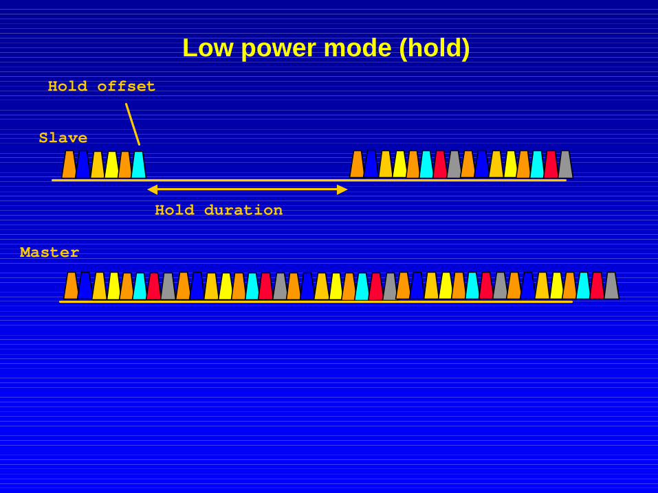
Low power mode (hold)
Slave
Hold duration
Hold offset
Master

Low power mode (Sniff)
Master
Slave
Sniff period
Sniff offset
Sniff duration
• Traffic reduced to periodic sniff slots

Low power mode (Park)
Master
Slave
Beacon interval
Beacon instant
• Power saving + keep more than 7 slaves in a piconet• Give up active member address, yet maintain
synchronization• Communication via broadcast LMP messages

Cluster Network Architecture (UCLA-WAMIS)
• Conceptcreate a cluster based TDM infrastructure which:
(a) enables guaranteed bandwidth for voice/video(b) can support mobility
• Approach– distributed clustering algorithm– time division slotting within each cluster– slot reservation for real time traffic– virtual circuits for real traffic; datagrams for data– code separation across clusters– slot synchronization
• Combines cellular radio and traditional packet radio features.

Lowest-ID cluster-head election
52
10
8
1 6
3
74
9

Distributed Cluster algorithm (lowest-ID)
• Each node is assigned a distinct ID.• Periodically, the node broadcast the list of nodes that it can hear.
– “ClusterHead” hears only nodes with ID higher that itself (unless lower ID specifically
gives up its role as CH) → A,B,C
– “Gateway” hears two or more CHs → G,H
– “Ordinary” node otherwise →• Properties
– No cluster heads are directly linked.– In a cluster, any two nodes are at most two-hops away, since the CH is directly linked to
any other node in the cluster.
RE: Emphremides, et al “A Design Concept for Reliable Mobile Radio Networks with Frequency Hopping Signaling” Proceedings of IEEE, Vol. 75, No.1, 1987
A
B
CG
H

Cluster network architecture
• Dynamic, distributed clustering alg. partitions the system into clusters.
• Code separation among clusters.• Local coordination provided within a cluster.• Clusterhead acts as local coordinator to
– resolve channel scheduling– provide power measurement/control– support virtual circuit setup for real time (voice and video) traffic– maintain synchronization
• Dynamic adaptation (via periodic updates)– mobility– failures– Interference – bandwidth requirements (B/W alloc.--TDMA slot assgn.)

Channel Access
• Control Phase:– clustering algorithm– routing– power measurement and
control– code and slot assignment– VC setup– acknowledgments
• Data Phase:– voice/video (PRMA)– data (Random Access)
… ..
frame
data phasecontrol phasefixed TDMA
on common code at full power
Within each cluster: time-slotted frame

Virtual Circuit support in WAMIS
Multimedia Traffic (eg, voice, video): • connection oriented; • QoS based admission control• VC based bandwidth allocation
We need:• robust, QoS enabled routing• “elastic”, reconfigurable VCs
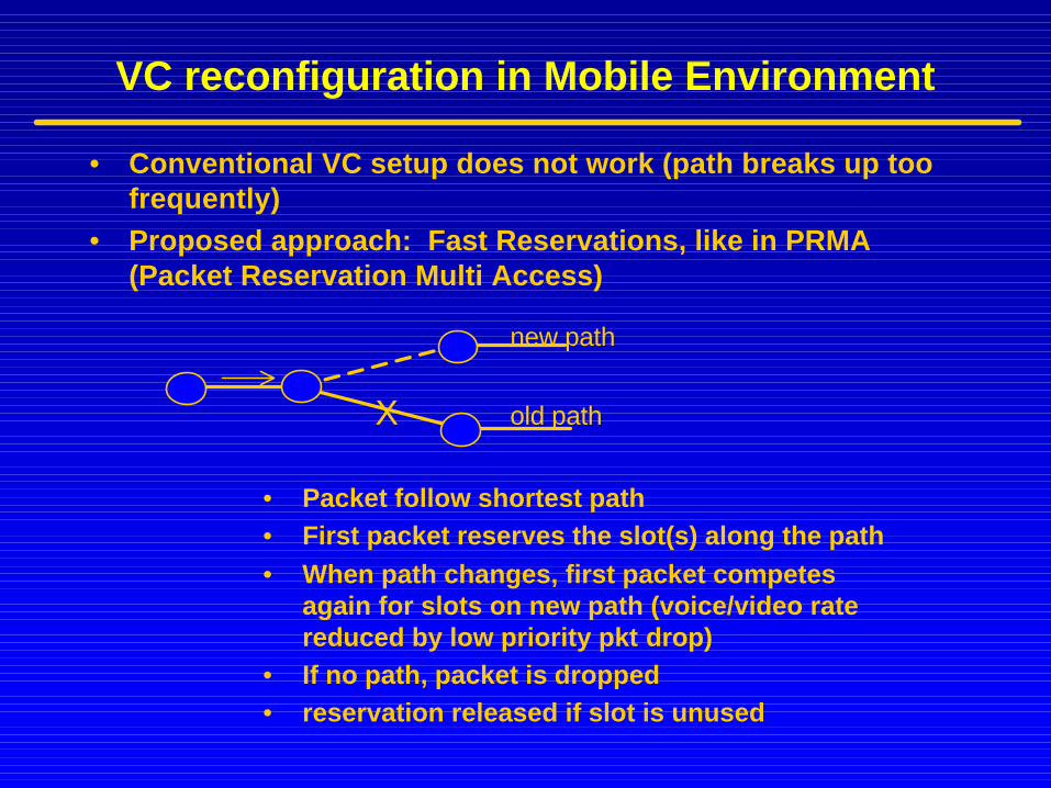
VC reconfiguration in Mobile Environment
• Conventional VC setup does not work (path breaks up too frequently)
• Proposed approach: Fast Reservations, like in PRMA (Packet Reservation Multi Access)
• Packet follow shortest path• First packet reserves the slot(s) along the path• When path changes, first packet competes
again for slots on new path (voice/video rate reduced by low priority pkt drop)
• If no path, packet is dropped• reservation released if slot is unused
X
new path
old path
Case study: compare Random Access and TDMA in Multimedia
C. Richard Lin and Mario GerlaComputer Science Department
University of California, Los Angeles

CSMA : DARPA PRNET (1970’s)
• Single channel• Spatial reuse • CSMA• Implicit ACK (echo ACK)• Retransmission (for datagrams only)• Duct routing (for voice traffic)
– Based on Bellman-Ford routing– Alternate routing: multiple paths used to carry multiple copies of a
real-time packet to improve reliability– Carrier sense will limit the fan-out

• Limitation of PRNET– no bandwidth reservations; no access control (for voice)– “hidden terminal” problem
• Enter Cluster TDMA (1994)– different codes in each cluster – TDMA type MAC access in each cluster– QoS routing; bdw reservation; access control– Fast VC set up (soft state)

• Problems of CLUSTER TDMA: cost and complexity– global slot synchronization– multiple codes– initialization
• Enter MACA/PR (1996) (Multiple Access Collision Avoidance/Packet Reservations)
– no clustering; single code; easy initialization– RTS/CTS dialog (to prevent “hidden terminal” problems)– Packet Reservations (to support real time traffic)– QoS routing; “standby” routs (for dynamic rerouting)

MACA/PR (cont’d)

Real Time Traffic Support: Bandwidth Reservation
• 1st packet is treated as a datagram packet • After 1st successful transmission: piggyback
reservation is honored for subsequent packets• Bounded delay and no collision• Real -time Traffic and datagram traffic are
interleaved (with datagram deferring to real-time traffic)
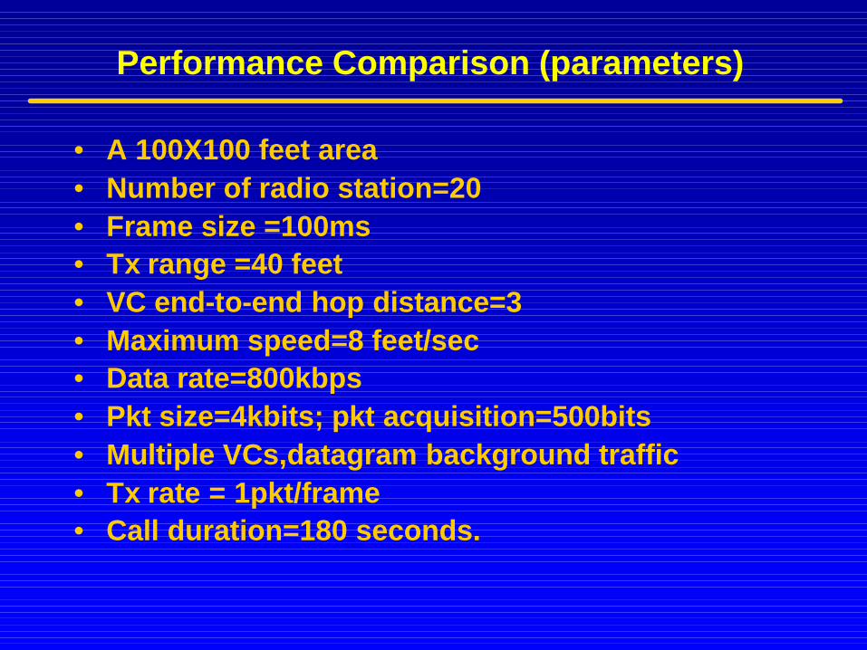
Performance Comparison (parameters)
• A 100X100 feet area• Number of radio station=20• Frame size =100ms• Tx range =40 feet • VC end-to-end hop distance=3• Maximum speed=8 feet/sec• Data rate=800kbps• Pkt size=4kbits; pkt acquisition=500bits• Multiple VCs,datagram background traffic• Tx rate = 1pkt/frame• Call duration=180 seconds.

Performance Comparison of Various Schemes
Synchronous Asynchronous
Cluster TDMA Cluster Token MACA/PR PRNET
Global synchronization
Cluster synchronization
Session synchronization
No synchronization
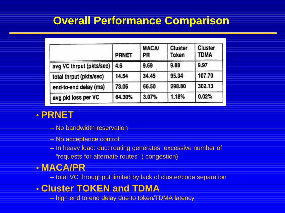
•PRNET–No bandwidth reservation
–No acceptance control–In heavy load: duct routing generates excessive number of
“requests for alternate routes” ( congestion)
•MACA/PR–total VC throughput limited by lack of cluster/code separation
•Cluster TOKEN and TDMA–high end to end delay due to token/TDMA latency
Overall Performance Comparison

Channel Propagation Models
Radio channel propagation is characterized by three main parameters:
• Attenuation: free space loss, absorption by foliage, partitions
• Shadowing: obstacles between transmitter and receiver• Multipath: due to the different phases on different paths

Simulator : Glomosim Channel ModelChannel Fading Model in Glomosim Simulator• the Simulator utilizes the SIRCIM impulse response parameters to
characterize the radio propagation model, i.e.: multipath, shadowing effect, spatial correlation

Radio Channel Simulation
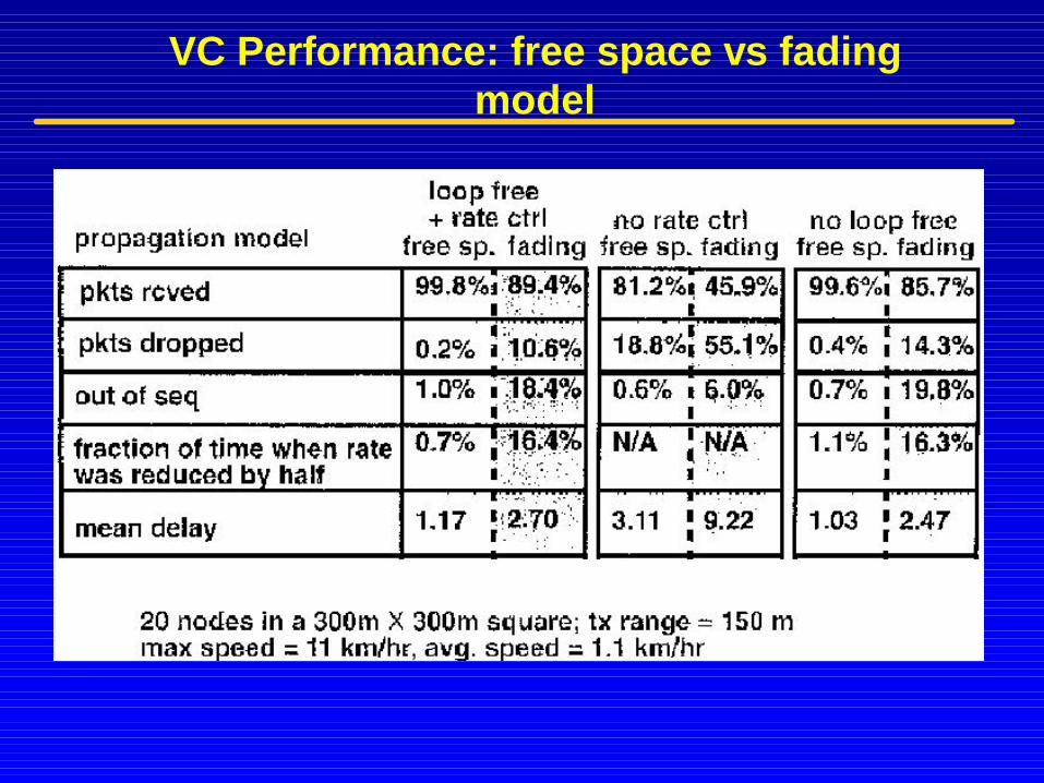
VC Performance: free space vs fading model