AD-A266 005 April US Army Corps II1I IIi11111 ll1 Il 11111 Report SL-93-5 AD-A266 005 April 199 US...
66
Technical Report SL-93-5 AD-A266 005 April 199 US Army Corps II1I IIi11111 ll1 Il 11111 of Engineers Waterways Experiment Station Investigation of Probable Causes of Cracking, Aircraft Weather Shelters, Kadena Air Base, Okinawa by Lillian D. Wakeley, Wayne G. Johnson, Patrick T. Harrington Structures Laboratory Approved For Public Release; Distribution Is Unlimited 93-13522 Prepared tor UJ.S,. Army Engineer District, Japan
Transcript of AD-A266 005 April US Army Corps II1I IIi11111 ll1 Il 11111 Report SL-93-5 AD-A266 005 April 199 US...

Technical Report SL-93-5
AD-A266 005 April 199
US Army Corps II1I IIi11111 ll1 Il 11111of EngineersWaterways ExperimentStation
Investigation of Probable Causesof Cracking, Aircraft WeatherShelters, Kadena Air Base,Okinawa
by Lillian D. Wakeley, Wayne G. Johnson, Patrick T. HarringtonStructures Laboratory
Approved For Public Release; Distribution Is Unlimited
93-13522
Prepared tor UJ.S,. Army Engineer District, Japan

The contents of this report are not to be used for advertising.publication, or promotional purposes. Citation of trade namesdoes not constitute an official endorsement or approval of the useof such commercial products.
%f PRiNTED ON RECYCLED PAPER

DISCLAIMEI NOTICE
THIS DOCUMENT IS BEST
QUALITY AVAILABLE. THE COPY
FURNISHED TO DTIC CONTAINED
A SIGNIFICANT NUMBER OF
COLOR PAGES WHICH DO NOT
REPRODUCE LEGIBLY ON BLACK
AND WHITE MICROFICHE.

Technical Report SL-93-5April 1993
Investigation of Probable Causesof Cracking, Aircraft WeatherShelters, Kadena Air Base,Okinawa
by Lillian D. Wakeley, Wayne G. Johnson, Patrick T. Harrington
Structures Laboratory
U.S. Army Corps of EngineersWaterways Experiment Station3909 Halls Ferry RoadVicksburg, MS 39180-6199
Accesion For
NTIS CRA&MDTIC TAB
Final report Urnannounced ElJustificationApproved for public release; distribution is unlimited ---------......... . ......
ByDistribution I
Availability Codes
Avail and / orDist Special
-1
Prepared for U.S. Army Engineer District, JapanCamp Zama, Japan

"U7,
US Army Corpsof Engineers
6W1R~tdENTALPUBLUC AFFAIRS OFFICE
LABO• ATORY -- U. S. ARMY E.HO"IN JEERWATERWAYS EXPERIMENT S'IAT1ON4300 IAUS FERRY ROAOVICKSS)URG, MtSIS•lPPI 3'91104-19
Waterways Experiment Station Cataloging-in-Publication Data
Wakeley, Lillian 0.Investigation of probable causes of cracking, aircraft weather shelters,
Kadena Air Base, Okinawa / by Lillian D. Wakeley, Wayne G. Johnson,Patrick T. Harrington ; prepared for U.S. Army Engineer District, Japan.
62 p.: ill.; 28 cm. -- (Technical report; SL-93-5)includes bibliographical references.I. Roofing, Concrete. 2. Concrete -- Cracking. 3. Hangars. 4. Air
bases -- Japan -- Okinawa-keri. I. Johnson, Wayne G. I1. Harrington,Patrick T. Ill. United States. Army. Corps of Engineers. Far East Dis-trict. IV. U.S. Army Engineer Waterways Experiment Station. V. Title.VI. Series: Technical report (U.S. Army Engineer Waterways ExperimentStation), qL-93-5.

Contents
Preface ............................................. iv
I-Introduction ... ..................................... 1
Sources of Data ..................................... 1Organization of Report ................................. 2
2-Concrete Materials and Condition ......................... 3
Physical Appearance and Properties ........................ 3Materials and Proportions ............................... 4Chemical Alteration or Degradation ........................ 5Crack Mechanism Indicated by Materials ................... 6Evidence for Drying Shrinkage Cracking .................. 6Susceptibility to Drying Shrinkage ......................... 7
3-Design Factors and Reinforcing ........................... 8
Unusual Load Condition ................................ 8Structural Design . .................................. 9Distribution of Reinforcing . ............................ 9
4-Interactions Among Concrete and Design Factors .............. 11
5-Static Analysis of the Structures .......................... 13
6-Dynamic Analyses and Field Measurements .................. 15
Global Model . .................................... 15Tests of Individual Panels .............................. 16
7-Conclusions . ..................................... 18
8-Recommendations ................................... 20
References . ........................................ 21
Appendix A: Trip Report: Kadena Air Base,28-31 Jul 92 . .................................... Al
Appendix B: Preliminary Findings Report: 17 Jul 92 ............. BI
SF 298
iii

Preface
This report was prepared at the Structures Laboratory (SL), U.S. ArmyEngineer Waterways Experiment Station (WES), under the sponsorship of theU.S. Army Engineer District (USAED), Japan. Mr. Jim Cox, Chief, Con-struction Division, was point of contact for the USAED, Japan.
Dr. Lillian D. Wakeley, Concrete Technology Division (CTD), was thePrincipal Investigator. MAJ Patrick T. Harrington, CTD, was ProjectCoordinator. Mr. Wayne G. Johnson, Structural Mechanics Division (SMD),conducted the static and dynamic analyses and modeling. Others at WES whocontributed to the study include Dr. Robert Hall, SMD, Mr. J. Pete Burkes,and Ms. Judy C. Tom, both CTD. This report was prepared byDr. Wakeley, Mr. Johnson, and MAJ Harrington.
Mr. Kenneth L. Saucier is Chief, CTD. Mr. Bryant Mather is Director,SL, and Mr. James Ballard is Assistant Director, SL.
At the time of publi-:ation of this report, Director of WES wasDr. Robert W. Whalin. Commander was COL Leonard G. Hassell, EN.
iv

1 Introduction
At the request of the U.S. Army Engineer District (USAED), Japan, theU.S. Army Engineer Waterways Experiment Station (WES) investigated thecauses of cracking in roof slabs of aircraft weather shelters at Kadena AirBase, Okinawa. Cracks had been observed on the upper surface of the roofslabs soon after the structures were built. With time, some of these crackspropagated through the slabs, appearing on the lower surfaces particularlynear the valleys of the folded-plate structures. WES initiated studies to deter-mine whether the cracks were related to materials, concrete mixture propor-tioning, field practice, static or dynamic loads, or some combination of thesefactors. Figure 1 shows a row of the shelters. Appendix A includes figuresshowing the underside of roof slabs and the geometry of beams and columns.
Sources of Data
The forensic investigations conducted by WES included data or informationfrom the following sources.
a. Discussions with Mr. Bruce Swafford, CEPOD, about his observationsof the subject shelters and study of a video tape he provided showingcracks in the concrete structures with his commentary.
b. Examination of 13 cores from these shelters, using petrographic andother forensic analytical procedures, to determine if cracking was at-tributable to concrete materials or mixture proportions or to chemicalalteration of materials after placement. This work was requestedspecifically in a memorandum for Dr. Lillian Wakeley, StructuresLaboratory (SL), WES, dated 4 Mar 92, from LTC Larry Talley,USAED, Japan (Okinawa Area Office). The subject of the memo-randum was Petrographic Analysis Support. WES issued a PreliminaryFindings Report following these laboratory studies (17 Jul 92;Appendix B).
c. Study of Architect Engineer (AE) design reports, specifications, con-crete test reports, as-built drawings, and crack maps as input to assess-ment of possible materials and structural contributions to cracking.
Chapter 1 Introductio-

d. Preliminary calculations to investigate possible structural sources of theobserved cracking or foundation deficiencies.
e. Review of the data with Mr. Jim Cox, USAED, Japan, during his visitto WES on 16 Apr 92. Mr. Cox provided more information aboutconstruction practices and other technical data during this visit.
f A site visit by WES researchers to Kadena Air Base during lateJuly 1992. This trip included collection of visual information for theshelters, collection of active impact data using a calibrated hammer,and collection of "ambient" data for one bay of the structure. Thelatter phase included excitation of Bay 30 of the structure by an F-15jet parked inside with the engine running (three tests) and taxiing of ajet through the structure (two tests). These activities were described ina trip report, included as Appendix A.
g. Analysis of data collected during the July 1992 site visit and calculationof fundamental frequency of structures.
Organization of Report
The following chapters describe the factors considered as possibly havingcontributed to concrete cracking: Chapter 2 is a study of the concrete as amaterial, its components and proportions, physical appearance and properties,and any evidence for chemical alteration. Chapter 3, foundation and designfactors, includes possible contributions by unusual loads and structural designand reinforcing. Chapter 4 focuses on the interplay of concrete materialsproperties with design and reinforcing. Chapter 5 presents an analysis of thepossible effects of various static loads. Chapter 6 and Appendix A describethe dynamic tests conducted during the site visit.
2 Chapter 1 Introduction

2 Concrete Materials andCondition
The 13 cores received at WES for petrographic and forensic study weretaken from roof slabs of shelter Bays 42 and 35. The core numbering systemand brief descriptions are given in Table 1. The cores represented bothcracked and uncracked portions of roof slabs as well as areas where waterponded on the roof. WES researchers requested cores from the ponded areasto compare with those from nonponding areas of the roof slabs. Theseprovided samples of concrete with varying likelihood for chemical degradationto have occurred.
Physical Appearance and Properties
Cores were photographed and visual descriptions were recorded before thecores were subdivided for petrographic study or destructive tests. All coreswere 102 mm long (4 in.), from 130-mm- (5-in.) thick roof slabs, so none ofthe cores represented the full depth of the slabs. Six cores were selected fordetailed physical and chemical study: three from each bay, both with andwithout cracks and reinforcing. Cracks were not directly associated withreinforcing; that is, some cracked cores included no reinforcing, and somecores that included segments of reinforcing were not cracked. Reinforcingwas corroded in only one core, where one reinforcing bar and one wire of thereinforcing fabric crossed the same crack. Cracks were roughly vertical ineach core; that is, they ran approximately perpendicular to the slab.
Entrapped air voids were visible in the concrete of all cores. Three coresshowed what appeared to have been water pockets on the undersides of aggre-gate particles and reinforcing strands. One core showed apparent segregationof aggregates, with no coarse aggregates in the upper 25 mm (I in.) of con-crete. The upper (finished) surfaces of two cores from Bay 42 had whatappeared to be a topically applied coating. The distribution of these featuresis summarized in Table 2.
3Chapter 2 Concrete Materials and Condition

In all cores, the uppermost strand of reinforcing encountered in the core is51 mm (2 in.) or more below the upper surface. The welded wire fabric,where present, is at least 25 mm (1 in.) up from the bottom of each core and,therefore, was 51 mm (2 in.) or more up from the lower surface of the slab.This evidence shows that depth-of-cover requirements were met. However,this arrangement puts the two layers of reinforcing less than 25 mm (I in.)apart, and in the middle of the slab. given that roof slabs were only 130 mm(5 in.) thick.
Design strength for the concrete was 27.6 MPa (4,000 psi). Cores testedby the Pacific Ocean Division Laboratory all met this strength requirement(information provided by Mr. Swafford), so WES did not conduct tests ofcompressive strength.
Materials and Proportions
The average value for cement content (American Society for Testing andMaterials (ASTM) C 1084 (1991c), six cores) was about 346 kg/cu m(584 lb/cu yd), which is higher than the 330 kg/cu m specified. Calculatedvalues for cement content are given in Table 3.
The coarse aggregate was crushed limestone. Fine aggregate includedcrushed limestone and apparently metamorphic ,ock fragments. A coarseaggregate solid volume of 58 percent was call-d for in the approved mixtureproportions. During our observations of slabs cut longitudinally from cores,we noted less coarse aggregate present than we expected to see in a structuralconcrete. The coarse fraction was missing from the upper 30 mm (3 cm) ofcore 920129 (Bay 35, ponding area). In all cores studied, coarse aggregatevolumes calculated from point counts (ASTM C 457 (1991a)) were lower thanthe value provided in information about mixture proportioning. For the coresstudied at WES, the volume of coarse aggregate ranged from 30.8 to43.5 percent (Table 4).
The average value for volume of permeable pore space or voids in hard-ened concrete (ASTM C 642 (1991b), six cores) was 14.5 percent. This ishigher than published values (13 percent or less) for volume of permeablevoids of similar concrete with water-to-cement ratio (w/c) = 0.5 (Whiting1988) and suggests that the w/c may have been higher than 0.5. Channels andlarge voids attributable to bleed-water collecting under reinforcing bars andcoarse aggregates are visible (Figures 2 and 3) in three cores (Tab!e 2). Inaddition to the 2.5 to 4 percent entrained air, up to 3 percent entrapped airwas present (Table 4), and much of it was easily recognized large voids. Theintended air content of the freshly mixed concrete as indicated by theapproved mixture proportion was 4 percent. The core with the most obviouswater channels along reinforcing bars also had the largest percentage of voids(by ASTM C 457 (1991a), > 7 percent), the most capillary porosity (ob-served during microscopy), a low cement content, and was cracked (Bay 35,core 118).
4Chapter 2 Concrete Material% and Condition

Chemical Alteration or Degradation
A combination of forensic laboratory techniques was used to study themicrostructure and phase composition of the concretes. These techniquesincluded polarized-light microscopy of petrographic thin sections, scanningelectron microscopy (SEM) with energy-dispersie X-ray chemical analysis,ai,,; X-ray powder diffraci in to identify crydtalline phases present in the pasteportion. The purpose of uis effort was to determine if the concrete had beenaffected by deleterious chemical changes while in service. We looked for:presence of weak or expansive crystalline phases in the cement-paste portionof the concrete; evidence of attack by chlorides or other ions associated withwet coastal environments; carbonation along cracks or elsewhere; chemicalinteraction with aggregates; association between reinforcing bar locations andmicrocracking; and evidence of any other chemical degradation process.
Our study revealed no evidence that deleterious chemical reactions hadcaused or contributed to cracking. The crystalline phases present were thoseexpected from normal cement hydration. The only unusual feature of thecement-paszte portion of the concrete, studied in thin sections and by SEM,was the presence of a large amount of finely divideu mineral matter ("fines"),as shown in Figure 4.
Aggregate surfaces v ere unreacted. We found only the expected back-ground level of chl, -rides in paste, at aggregate surfaces, and along cracks.Ettringite, a phase that can cause cracking if it forms in a restrained condition,was minimally present on free crack surfaces (except where cracks were car-bonated, as explained below); however, it was not in an amount or config-uration to indicate it had caused the cracks to form. Ettringite appeared tohave crystallized on free surfaces of preexisting cracks (Figure 5) and was notpresent in open pores in the paste (Figure 3).
Reinforcing strands were corroded where they were colocated with cracksbut not elsewhere. From this we conclude that the reinforcing was not cor-roded before being used in construction. The corrosion observed was mini-mal, thus indicating that it occurred along cracks that had been initiated bysome other mechanism and that the corrosion did not cause cracking.
The pattern of carbonation revealed more about the cracking than did anyof the other techniques. Open crack surfaces were carbonated from the uppersurface of the slab down to a depth of about 30 mm (1.3 in.) (Figure 6).From the surface to this depth, cracks had stepped carefully around coarseaggregate particles. Below 30 mm (1.3 in.), crack surfaces were not carbon-ated, and the cracks wandered both around and through coarse aggregateparticles (Figure 7). Relative to the rate of crack propagation, carbonationwas a slow process. Thus, the cracks have been open longer at the top of theslabs where the surface is carbonated and are younger downward.
The relationsLip betw,,en cracks and aggregates indicates the same trend.If the upper part of the slab cracked soon after placement, the paste wouldhave been weaker than the aggregates; therefore, only the paste cracked.
5Chapter 2 Concrete Materials and Condition

Later, the concrete had gained strength, so that the strengths of the paste andaggregates were similar. Cracks then propagated without differentiatingbetween them, leading to the lower zouie of cracking through both paste andaggregates.
Crack Mechanism Indicated by Materials
It is likely that cracks were initiated early in the life of the structures bydrying shrinkage. The following is background information about this crackmechanism, which is explained in American Concrete Institute (ACI)224.1R-3 (1992). The volume of hardened portland cement changes withchanges in moisture content. The combination of moisture-caused volumechanges and restraint of the concrete--in this case, probably by beams andcolumns--causes tensile stresses to develop, and this can initiate cracks.Cracks then may propagate at much lower stresses than were required toinitiate them.
Evidence for Drying Shrinkage Cracking
Several lines of evidence support the hypothesis that these cracks probablywere initiated by drying shrinkage. According to field personnel, cracks wereobserved on the upper surfaces of roof slabs within the first few weeks tomonths after concrete placement. Cracks started appearing on the lowersurface sometime later. During the study it was confirmed by petrographictechniques that cracks in the cores are older -t the top (toward the uppersurface of the slab) and younger into the depth of the slab. This is consistentwith cracks having been initiated by drying shrinkage and later propagated byother stresses.
Additional evidence for probable drying shrinkage cracking is offered bymixture proportions. The proportions of the concrete mixture used in thisconstruction made it susceptible to drying shrinkage cracking. The concretewas pumped upward in each column to encase a preexisting steel structure,and it appears to have been proportioned for ease of pumping. The sameconcrete mixture then was used to cast the beams and slabs in place. Specifi-cally, the concrete in the cores of the study had: a relatively high fineaggregate content, fines in the paste portion: a w/c of 0.5 or higher. lesscoarse aggregate than was indicated in mixture proportioning informationprovided, and small coarse aggregates (apparently 19-mm (0.75-in.) maximumsize). All of these factors made the concrete more pumpable. while at thesame time making it more susceptible to shrinkage cracking. An increase inslump, from 7.62 cm (3 in.) to 10. 16 cm (4 in.), was allowed. As indicatedby field personnel, the roof slabs were cured using wet burlap.
Another line of evidence for drying shrinkage having initiated the cracks isthe crack locations. Most cracks are located where the concrete would experi-ence large stresses during curing: parallel to the column line and closer to the
6 Chapler 2 Concrete Materials and Condttion

trough than to the peak of each shelter roof. They initiated on the upper sur-faces of the slabs, and these surfaces were not restrained by beams andcolumns.
Susceptibility to Drying Shrinkage
On the subject of concrete being susceptible to drying shrinkage, ACI224R-41 (1992), Section 8.6.3 says in part:
... too often, to expedite pumping, the actions taken are thosewhich increase drying shrinkage and resultant cracking: moresand, more fines, more water, more slump, smaller aggregate.
The concrete used in the aircraft weather shelters had all of these charac-teristics. Pumping per se is not harmful to fresh concrete. Large amounts ofhigh-quality, even high-strength, concrete are pumped worldwide every day.However, factors that affect the long-term serviceability of a structure shouldbe considered as important as those that make fresh concrete easy to pump.
Chapter 2 Concrete Materials and Condition

3 Design Factors andReinforcing
In the initial considerations of the causes of cracking, WES included thefoundation of the structures as a possible contributor. However, the pattern ofcracking in the shelteii does not correspond to patterns known for foundationproblems. There is no evidence of cracking of the base slab or cracking inthe fire walls between certain bays of the structure, as would be expected ifthe foundation were deficient. Further, the cracking pattern is reasonablyuniform over the entire site. Foundation problems gn.erall, result inlocalized structural problems. Following discussions with Mr. Cox and studyof AE design documents and maps of crack patterns, it was concluded thatfurther consideration of foundation characteristics would not be helpful.During the initial studies (before the site visit), the following structural factorswere considered as possible contributors to cracking.
Unusual Load Condition
Discussions with area engineers revealed that the structures have been sub-jected to significant wind loads, both from daily fluctuations and fr( m at leasttwo typhoon-class storms between the time the structures were comrleted andthe time of our study. However, the apparent wind speeds were smaller thanthe values used for design. Ambient conditions at Okinawa also cause struc-tures to be exposed to daily temperature fluctuations of up to 27 °C (50 'F),Both winds and temperature changes could contribute to frequent loadreversals.
Another source of nonconstant loads is the vibrations associated with jetengines as the planes move in and out of the shelters. The presence of crack-ing prior to use of the shelters guarantees that these vibrations cannot haveinitiated the cracks. However, these vibrations were considered a likely causeof propagation of cracks after they had been initiated by some other mecha-nism. Thus, they were the principal subject of our field measurements, de-scribed in Chapter 6. They were relatively small but significant enough toexcite certain modes of vibration in the shelters to a level significant enoughto record. Information collected does not suggest that the engine vibrations
8Chapter 3 Design Factors and Reinforcing

are causing uny significant damage to the structures, as is discussed in moredetail further into this report.
Structural Design
A review of the design for location of reinforcing in the roof slabs andbeams revealed no significant design deficiencies, although several questionswere raised during the review. The design was reviewed by the original AEcontractor (after construction) and by design engineers at USAED, Japan. Forthis reason, a thorough design review was not conducted by WES. AEresponses to questions raised by USAED, Japan, about the design appear tohave been adequate and reasonable.
Our main concern about the design is the use of thin slabs in associationwith deep girders at the column head. This is not an unusual practice for flatstructures, but the folded-slab configuration complicates the load distributionfor the aircraft shelters. The continuous slab design of the shelter roofs isanalogous to a continuous highway bridge. This configuration causes the thinslab at the top of the section to be in direct tension throughout its depth. Thissituation exists because the neutral axis of the beam/slab system lies beneaththe bottom of the slab. For this reason, any cracking due to flexure of theroof would be expected to be perpendicular to the plane of the slab and extendthrough it. As described in Chapter 2, cores taken through cracks in the slabsrevealed that the cracks are approximately perpendicular to the plane of theslab. This gives credence to the argument that propagation of the cracking isprimarily the result of flexure of the continuous-slab configuration.
Distribution of Reinforcing
Several changes were effected during construction of the weather shelters,after cracks were noted in the first nine shelters. The presence of a bend inthe top steel layer of the roof slab at the column head contributed more flexi-bility to the joint of the roof slabs with the column support area. This detailwas delineated as a problem in the inspection report of 1 Sep 89, a copy ofwhich was provided to WES. When it was judged that these bends contri-buted to cracking in the first nine shelters, the bends were eliminated, andadditional steel was added to the slab at the supports for the remaining struc-tures. This is not considered to be a dangerous situation; however, the roofslabs for these first nine structures are inherently more flexible than the slabsfor the newer structures due to the combination of this detail plus less totalreinforcing.
After elimination of the bend and the increase in total reinforcing in theslabs, cracking still occurred. In general, the cracking became less severe andthe cracking pattern changed somewhat after the modification. Figure 8 givesa comparison of cracking geometry for two bays of the structure as suppliedto WES by USAED, Japan, personnel. It shows a distinct difference in
9Chapter 3 Design Factors and Reinforcing

cracking geometry following placement of additional steel and elimination ofthe bend just described. Although this is a limited comparison, it appears thatin the newer structures (with additional steel) the cracks have been forcedfarther up the slope. In some cases, the direction of the cracks has changedfrom parallel to the valleys to perpendicular to the valleys. This points to theflexibility of individual slab "panels" in the stucture, but for the comparisongiven in Figure 8, this could also be the result of boundary conditions. Bay35 has one "free" edge and one continuous edge while both edges of Bay 43are continuous. Individual panel flexibility is brought about by the largewidth-to-thickness ratio of the panels (minimum of approximately 22:1) andthe placement of steel with respect to the panel depth.
As implied previously, another concern is the placement of steel relative tothe thickness of the roof slab. Cores taken from the slabs confirmed that thesteel layers were separated by a small distance relative to the slab thickness.The required cover depth of concrete was the driving factor for the steelplacement design. The requirement was a 51-mm (2-in.) cover depth for thetop layer of steel and a 38-mm (1.5-in.) cover depth for the bottom layer ofsteel. This depth of cover is good practice in coastal environments to detercorrosion of the reinforcing. In the thin roof slabs, however, the cover speci-fications resulted in an effective separation of less than 25 mm (I in.) for thetwo layers of reinforcing steel. Although the slab was designed for this valueand the design conforms to standards (thus, it is safe), this configurationresults in flexible individual slab panels within the beam framework. Thisflexibility appears to have contributed to the cracking (Chapter 4).
Further evidence for the above argument is found in the changes in crackorientation following addition of steel at the column heads. In the originalnine structures, almost all cracking is parallel to the valleys of the structureand is located near the valleys. Further, the cracks do not appear to extendacross the girder areas. This points to excessive stresses in the individual slabpanels brought about by negative moment loads at the column heads. Thegirders are sufficiently reinforced to resist cracking; however, the slab panelsappear to crack due to direct tension over the column heads resulting fromnegative moment at these points (and possibly exacerbated by reversing loads).In the newer structures, it appears that many of the cracks have changedorientation, which indicates that the additional steel may have been adequateto handle the direct tension over the columns but not adequate to handleindividual panel loads (probably dominated by wind). No additional steel wasadded in the orthogonal direction, thus cracking occurred in the weaker direc-tion. For Bay 35, the change in crack orientation at the free edge could alsobe partially attributable to boundary conditions (Figure 8).
10 Chapter 3 Design Factors and Reinforcing

4 Interactions AmongConcrete and DesignFactors
As presented in Chapter 2, the concrete used in construction of the weathershelters was susceptible to cracking by drying shrinkage. Cracking of thistype is likely to be distributed more or less uniformly over all of the slabs, asis the case here. Similar damage in virtually all bays suggests a problem witheach individual slab (a slab is considered to be one-half of the roof for anindividual bay). Drying shrinkage cracks are unlikely to extend the full depthof the slab. Given that the cracks propagated over time, extending throughthe slabs sometime after the cracks were first observed, it is probable thatsome other factor(s) contributed to crack propagation.
As discussed in Chapters 2 and 3, the most likely two factors contributingto cracking are concrete drying shrinkage and structural design. Either factorcould explain the longitudinal cracking pattern in the valleys of the shelters.However, the available information implies that the cracks extend through thedepth of the slabs. This is unlikely to have resulted from drying shrinkagealone and is most likely explained by shrinkage coupled with tension due toflexure of the slab/girder system.
One point of concern with the hypothesis that cracking was initiated byshrinkage is the presence of diagonal cracks at the corners of the slabs. This,at first glance, would not appear to be attributable to shrinkage. In general,this would likely be due to a structural design problem. However, no struc-tural deficiency that would have led to this type of damage is obvious. Fur-ther, the fact that the cracking was displaced farther to the interior with theaddition of diagonal reinforcement tends to provide evidence that diagonalcracking could have been initiated by shrinkage of the concrete.
The structure is very stiff in the direction parallel to the valley at the eleva-tion of the valley. It is also very stiff in a direction transverse to the valley(across the gable) due to the frame system. The structure is less stiff in thelongitudinal direction (parallel to the direction of entrance/exit) at the peak ofthe gable. Thus, shrinkage would first be expected to produce cracks parallelto the longitudinal direction at the peak or the valley and transverse to thelongitudinal direction (up the gable) near the valleys. If the structure were
Chapter 4 Interactions Among Concrete end Design Factors

equally stiff in the longitudinal direction at the peak, shrinkage cracks wouldbe expected up the gable slopes at one or both ends. However, since thestructures are not as stiff at the peaks, it appears that the diagonal cracks aremore or less the result of the transition from the stiff valley to the more flexi-ble peak. The fact that the cracks, once begun, propagated with time andperpendicular to the plane of the slab is a strong piece of evidence supportingthis hypothesis.
Not all of the damage can be attributed to cracks initiated by dryingshrinkage. There is evidence of some cracking on the underside of the girdersnear the peaks. Tension in these areas would occur if the slabs weresubjected to reversing loads.
12Chapter 4 Interactions Among Concrete and Design Factors

5 Static Analysis of theStructures
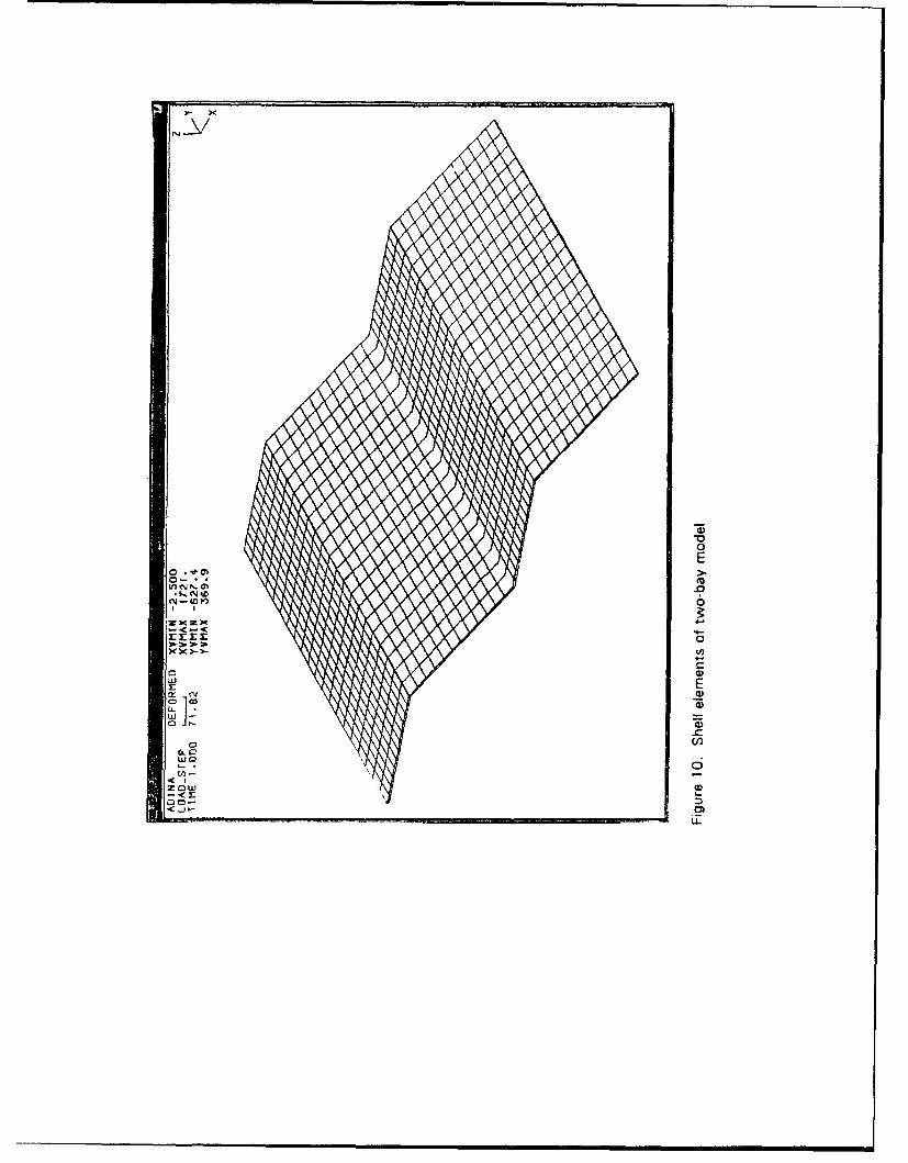
Before the site visit, a simple finite element model was developed at WESto investigate possible structural weaknesses that could have contributed to theobserved damage. The model consisted of only the roof portion of a two-baysystem. It encompassed beams to model the beam/girder system coupled withshell elements to model the slabs. Linear-elastic material properties wereassumed. Figure 9 shows the beam system with node numbers. A fine gridwas necessary tw, define the problem. The beam portion of the model con-sisted of 548 beam elements. The slab portion consists of 960 four-node shellelements (Figure 10).
Seven loading scenarios were selected, based on our experience with fail-ure analysis for other structures. These options (Cases I through 7 in thefollowing discussion were intended to reveal whether or not the crackingpattern could be related directly to a particular type of loading on the struc-ture, ignoring nonstructural (i.e. materials) contributions to cracking. Thecases selected dealt primarily with movements of structural support andincluded:
a. Static loading only.
b. Lateral movement of one edge away from the center.
c. Twisting of one exterior wall.
d. Settlement of a line of columns at an exterior edge.
e. Settlement of an exterior column.
f. Settlement of a line of columns along the valley.
g. Settlement of an interior column.
The model identified areas of greatest tensile stress and most likely cracking,assuming various displacements of up to 25 mm (1 in.) at certain nodes.
Chapter 5 Static Analysis of the Structures 13

Case 1 is the simple static condition. It revealed larger stresses perpen-dicular to the valley on the top face of the shell elements and also near thepeaks (Figure I1). The crack map of the Kadena shelters (as shown in Fig-ure 8) indicates a stress distribution similar to that predicted by this case,which gave the best fit of those we considered. Stresses along the valleys ofthe real shelters probably are even greater than those indicated by this case,due to the presence of the flat segment joi-'ing the two slopes of adjacent bays(the model has a v-shaped valley).
Case 2 models an outward rotation of an exterior wall, which is a type ofsway response. This model gives a good match for the observed crackingpattern. However, given the connected arrangement of the shelters, each bayis highly restrained from sway. Given that cracks are present in virtually allbays, this type of response probably does not explain the cracking. Likewise,Case 3 models twisting of one exterior wall of a two-bay system. This typeof twisting would result in localized stresses, with cracking along the peak atone end of a bay and in the valley at the opposite end. Again, the structuresshow no evidence of having experienced this type of movement, given theircrack distribution and connected arrangement. We considered the possibilitythat jet loads on the structures might produce this type of response. However,field measurements taken during our site visit (described in Chapter 6) implythat routine traffic loads are not large enough to produce stresses of this type.
Case 4 depicted a differential settlement problem. We judged this scenarioto be unlikely given that floor slabs are not cracked and the damage is toouniformly distributed. Cases 5 and 6 also resulted in highly localized stresspatterns, unlike the crack pattern of the shelters. Case 7 is similar to Case 5,giving highly localized foundation movement. The movement implied wouldinvolve several columns in a row, again giving a probable crack pattern that isnot consistent with field observations.
Figures showing the stress patterns that would be generated in the two-baysystem by these seven load scenarios are on file at WES and are available onrequest.
Chapter 5 Static Analvsis of the Structures

6 Dynamic Analyses and FieldMeasurements
WES also investigated dynamic properties of the shelters, looking forevidence that structural integrity or performance might be jeopardized by thecracks (and to verify the mathematical model). These investigations includedcalculations for the same two-bay model described before as well as investiga-tion of one slab panel of the roof. Results of these calculations were com-pared with data from active tests: that is, collected during the site visit.Results from the model compared favorably with data taken during the activetests (the model was appropriate to the structures). In the following discus-sion, the term "global" refers to the entire two-bay structure (or its modelequivalent), and "local" indicates only a single panel (or model).
Global Model
Calculated fundamental frequencies for the global model are relativelysmall. Figure 12 shows the lowest three calculated frequencies. Since it wasnot practical to collect data for the entire two-bay structure corresponding tothe global model during our site visit to Kadena, the dynamic investigationconcentrated on the local response for individual slab panels. Thus, thefrequency range of interest was higher than would have been investigated forthe entire structure.
There was evidence of one or more of the lower global modes present insome of the local data collected from a single slab, as is indicated in the low-frequency portion of the power spectrum shown in Figure 13. Excitation ofthe first global mode of response (Figure 12a) could result in cracking patternssimilar to those observed in the structure. Cracking parallel to the valleys andat the underside of the girders near the peaks could be attributed to excitationof this fundamental global mode, as might be affected by wind loads. Unfor-tunately, the resolution for the lower frequency ranges was not adequate todetermine if these global modes were being excited by ambient conditions.Also, the frequency range of interest for these global modes is at the low endof the effective range for the accelerometers used in the investigation. There-fore, the evidence for excitation of these global modes is inconclusive.
Chapter 6 Dynamic Analyses and Field Measurements 15

Tests of Individual Panels
The first three calculated fundamental frequencies and mode shapes for anindividual slab panel (local model) are given in Figure 14. The boundaryconditions for these calculations include rotations and displacements fixed forall nodes at the perimeter of the panel. Actual boundary conditions for thepanels apparently varied slightly from this condition.
Nondestructive impact tests were conducted for three slab panels of Bay30, defined in Figure 15. The grid of 17 points used for collection of datafrom each panel is shown in Figure 16. Tests were performed using aninstrumented impact hammer and one accelerometer.
An undamaged panel (UPI) was selected to provide baseline data. Fig-ure 17 displays the experimental fundamental vibration mode for this panel.The shape of the fundamental mode derived experimentally is strikingly simi-lar to the calculated mode (Figure 14b). The fundamental frequency deter-mined from test results was 46.25 Hz, compared to a calculated fundamentalfrequency of 45.65 Hz. Experimental results from modes 2 and 3 are shownin Figures 17b and 17c. The frequency values are not as close to the calcu-lated values as they were for mode 1 (Table 5), but the patterns are still nota-bly similar.
The damaged panels (DPI and DP2) chosen for impact tests representedtwo of the more common crack configurations. One panel (DPI in Figure 15)had a diagonal crack across one corner and penetrating the full depth of theslab. The same procedures were used for this panel as were used for theundamaged panel to define the mode shape. Figure 18 shows the first threeexperimentally derived modes for DPI. The results for this mode of DPIappear to be identical to those of the undamaged panel. A minimal effect ofthe crack on structural behavior is indicated. The second and third modes forthis panel compare very well visually with experimental results for UPI andwith calculated results.
DP2 is located as indicated in Figure 15. Damage to this panel consistedof a longitudinal crack running parallel to the long dimension of the slab andapproximately 1.5 m from the valley edge of the panel. The experimentalfundamental frequency for the first mode was 46.25 Hz, the same as it wasfor the other two panels. The first three mode shapes are presented in Fig-ure 19. Table 5 gives a comparison of the first three frequencies for thecalculations and test results.
Data were collected for five additional tests during aircraft activity withinBay 30. For these tests, a reference channel was maintained on the undam-aged panel, and three other gages were used to collect the data sets. Three ofthese five tests involved the jet parked inside the shelter with engines runningat normal maximum (described by the pilot as "revved to 80 percent"). Twoadditional data sets were recorded with the jet taxiing out of the shelter. Bothof these situations are typical of everyday use of the shelters.
16 Chapter 6 Dynamic Analyses and Field Measurements

For each of the three revving tests, data were collected for a period of30 see while the engines were accelerated from idle to normal maximum. Inaddition to the data collected from the undamaged panel (UPI) for each test,the first test collected data from DPI, the second from a beam between UPIand DPI, and the third from a column near DPI on which the gage wasmounted horizontally.
Figure 20 shows the power spectra for each of these three stationary tests,with data from the two channels open for that test (reference values plus testdata). Each curve represents the averaging of 5,000 time segments of data,which reduces random noise significantly. As was true of results from theimpact tests, these data indicate very similar dynamic properties for the dam-aged and undamaged slab panels and imply minimal effect of the crack onstructural performance during everyday operating conditions.
The two taxiing tests compared UPi first with DPI and then with the beamseparating UPI and DPI. Power spectra are plotted in Figure 21, againcomparing data from pairs of channels. The results are consistent with thoseof the previous tests: (a) very similar dynamic properties for all members andconditions tested; and (b) the expectation of structural performance fromcracked slabs similar to that of the intact portions of the shelter-roof panels.
17Chapter 6 Dynamic Analyses and Field Measurements

7 Conclusions
Although the concrete used in construction of the aircraft weather sheltersmet strength requirements, it was not resistant to cracking. The concreteappeared to be proportioned for ease of pumping into the column forms.While its proportions were appropriate for pumping, they also made it moresusceptible to drying shrinkage cracking in the thin roof slabs. Although theinformation provided indicates that the roof slabs were cured with wet burlap,the present level of cracking suggests that the surface was not keptcontinuously wet for a long enough time after the concrete was finished.
Design and placement of reinforcing was driven by the requirements fordepth of concrete cover over steel in a coastal environment. Again, the coverrequirements were met. But in roof slabs only 130 mm (5 in.) thick, thisresulted in both layers of reinforcing being compressed into the center of eachslab (between 50 and 76 mm (2 and 3 in.) from either surface), diminishingtheir effectiveness.
Cracking was not initiated by unexpected loads or by vibration associatedwith jet engines. Cracks were visible in roof slabs very soon after the
concrete hardened, before any severe weather on Okinawa, and before theshelters housed any aircraft.
The concrete has not experienced any deterioration from chemical attack.aggregate reactionq, corrosion of reinforcing, or ether environmental factorsknown to cause distress to concrete.
Cracks were initiated by drying shrinkage soon after concrete placement.Cracks are older at the top, so propagation of cracks through the full depth ofthe slabs required more time. Cracks propagated through the slab almostexclusively near the valley of each folded plate. Crack propagation wascaused by factors unrelated to shrinkage.
Foundation settlement or movement did not contribute to the observedcracking. Evidence of foundation movement would he shown by cracks infloor slabs, vertical fire walls, or columns of the structures. No such damagewas reported or observed.
Propagation of the cracks is attributed primarily to flexure along the
column lines. This flexure may be augmented by reversing wind and thermal
18 Chapter 7 Conclusons

loads on the shelters. Although propagation of existing cracks is likely tocontinue, appearance of new cracks is unlikely if use and load conditionsremain the same.
As determined by onsite measurements dynamic characteristics of anundamaged panel are basically the same as thcse of a cracked panel. There-fore, the shelters have not experienced significant structural deterioration.
No structural modifications appear necessary beyond those alreadyeffected. The membrane placed over the structures should slow the movementof moisture to the reinforcing steel through existing structural cracks. Deteri-oration of the reinforcing steel over time, ensuing stress on the paaels, andloss of structural strength presents the most notable risk to long-term perfor-mance of the weather shelters.
Chapter 7 Conclusions

8 Recommendations
Careful inspection of all bays of the structures should be conducted atregular intervals. Any evidence of deterioration should be investigated andevaluated for potential structural risk. This includes evidence of corrosion ofreinforcing steel, as shown by staining on the undersides of slabs. The mois-ture retarding membrane over the structures should also be inspectedregularly. (Some leakage of the membrane was observed during the WES sitevisit to Kadena. This was reported to USAED, Japan, personnel.)
A thermal analysis of the slabs could be performed to determine whethertemperature effects are a factoi 1 the cracking. Heat dissipation is a greaterproblem in the more massive bean~is than in the thin slab.
20Chapter 8 Recommendations

References
American Concrete Institute. (1992). ACI manual of concrete practice.Part 3, ACI 224R and 224. IR, Detroit, MI.
American Society for Testing and Materials. (1991). 1991 annual book ofASTM standards. Philadelphia, PA.
a. Designation C 457-90, "Standard test method for microscopical deter-mination of parameters of the air-void system in hardened concrete."
b. Designation C 642-90, "Standard test method for specific gravity,absorption, and voids in hardened concrete."
c. Designation C 1084-87, "Standard test method for portland-cementcontent of hardened hydraulic-cement concrete."
Whiting, D. (1988). "Permeability of selected concretes." Permeability ofconcrete, ACI SP-108, D. Whiting and A. Walitt, ed., American ConcreteInstitute, Detroit, MI, 195-222.
21References

Table 1Core Samples Identification and Description
Core WES/CTDSample Number Description
1 920109 Upper portion of Bay 42 roof slab, no cracks observed
2 920110 Same as core 920109
3 920111 Same as core 920109
4 920112 Lower portion of Bay 42 roof slab, crack observed
5 920113 Lower portion of Bay 42 roof slab, no cracks observed
6 920114 Valley portion of Bay 42, above girder No. 6, ponding area,no cracks observed
7 920115 Same as core 920114
8 920116 Upper portion of Bay 35 roof slab, no cracks observed
9 920117 Same as core 920116
10 920118 Lower portion of Bay 35 roof slab, crack observed
11 920119 Lower portion of Bay 35 roof slab, no cracks observed
12 920120 Valley portion of Bay 35 near column head, ponding area,hairline crack observed
13 920121 Same as core 920120

Table 2Distribution of Macroscopic Features in Six Cores
Bay 42 ..... .... Bay 35
Core-Feeture 109 112 114 J116 1118 120
Entrapped Air X X X X X X
Reinforcing X X X X X
Crack X X X
Carbonation X X X
Water Channels X X X
Aggregate Segregation X
Surface Coating X X
Table 3Cement Content of Cores as Determined by ASTM C 1084(1991 c)
Core Identification j Cement Content, lb/yd3 lkg/mM3
920111 577 (342.3)
920113 571 (338.7)
920115 599 (355.3)
920117 586(347.6)
920119 558(331.0)
920121 612(3631)i
Average 584 (346.3)

Table 4Air Voids and Solid Components by Volume as Determined by ASTM C 457(1991 a)
WES Core N~umber
Material/Void Type 109 112 114 116 118 120
Percentage by Volume
Coarse Aggregates 30.8 43.5 34.0 34.3 38.9 31.5
Fine Aggregates 31.5 26.1 29.9 28.6 25.6 29.4
Cement Paste1
33.2 24.8 30.5 32.1 28.5 34.9
Entrained Voids 3.0 3.1 4.4 2.6 4.0 2.9
Entrapped Voids 1.6 2.6 1.2 2.4 3.1 1.3
Total Voids2
4.6 5.7 5.6 5.0 7.1 4.2
1 The paste portion includes a notable amount of very finely divided mineral matter probably derived from the
aggregates.2 Total of entrained plus entrapped air, which are counted separately and differentiated on the basis of void
size and shape.
Table 5Comparison of Calculated and Measured Frequencies
Computer Model UP1 DP1 DP2
Mode (HzI (Hz) lHz) (Hz)
1 45.7 46.2 46.2 46.2
2 77.0 85.3 89.6 89.0
3 107.7 109.3 106.4 114.8

Figure 1. Kadena Air Base aircraft shelters

0
U,
u _
o5 0 oa
2E
0) 0
CM
0)
CO
E CoCot
o-Z

c c
-- C0O
2EU0 Z
-00
wco W=
*0 M
CL-
LO
c E,
Oki- L.

U) 0
o C
m0)
CL
CD- 0 ,5 -
~00)
Q 0.0
(0
m C

----- CAI --- ---I I rI •
. I
I . .. .. .. .. I I
a. Bay 35 ........... INDICATES APPRaXIMATE
CRACKING PATTERN
jj - -
Ii : :1
-. -- - ---...-
I I
b. Bay 43
Figure 8. Plan view of Bays 35 and 43, showing locations of beams and
cracks; peak of each folded plate is in the center of the bay

'IV7
C~do
I~e0
0
4,0)
0 c)
['I E
0 MViMe-M 010
zow 4-V"
o Mi-0
C,00
m E
0 a?
00
CLC
LE


0i C
0~~i .2 0 0 C; c
1ý 00
.r VV
0
i.o~
CL 0
W0
LL

a. Mode I
--. ~ lI I *,al aCM* l.A. p" am6•. •,..
b. Mode 2
mam ..... . .M fl I I.. ...
c. Mode 3
Figure 12. First three calculated mode shapes for global two-bay model

U-A D-8 CF-366 PORTfGLE DUA}L CHANNEL FFT ANALYZER
11i081Hz A:ACy SeV B:AC/ 5eV INST 8/16 DUAL 1k
-46
V
MAG
-1 0d e / IV. ......
-1@6 1. tve PWR SP A han LIN 588Hz
]: @ie.75Hz D* -75.06dBV
Figure 13. Power spectrum showing evidence of lower global modes in local data (peaks atfrequencies less than 40 Hz)

CW"L - ~ i 0
MZ
..............
0
E
2N
"uiw
c-
00
0
C.- "D
0
w0. Li
0L

BAY 30
IDIRECTION OF TRAFFIC
I¢, r• "-< tlk*,
1DP2
Figure 15. Plan view of roof of Bay 30,showing locations of UP1, DP1,DP2, and cracks; arrow marks
roof peak and shows directionof aircraft traffic
'\I /7
P1P16i• l,6 ,/
\ I /1
I \ I / I
I P6
P1 P2~ 1 P34
Sp7 pl\ /I, 1I i
I I \/ I\ I
I I /lf \ I I
,,P' I- "-P, I
I /
Figure 16. Grid for 17 impactpoints in testedpanels

"-o
a. Mode 1
2 '
b. Mode 2 c. Mode 3
Figure 17. First three modes for UP1 as determined by impact tests

&
a. Mode 1
V °
b. Mode 2 c. Mode 3
Figure 18. First three modes for DP1 as determined by impact tests

a. Mode I
b, Mode 2 c. Mode 3
Figure 19, First three modes for DP2 as determined by impact tests

U-A D--e CF*-360 PORTA1LE CUAkL CHAIIHEL EFFT ANALYZER5eaHz A:min sev e / '5oy s.sum seee/5eee *~mar
HAG
28d8/-94 P4 SP1 hn LM MHz
X; 10.68Hz Y:, -98.58dOV
HAGdBV
28dS/
~10.800"z V: -107.e8d9V
a. Test 1
lU-A B-B CF-360 PORTABLE DUAL CHANNEL FFT ANALYZER2844Hz A.C SOV 8.,C2 58V S.SUt1 5804,56808 !f~
-4e
HAGdeIV
2edBZ
-10 -P1.6 SP AhaA LIN 50EIHzRX 62.56Hz Y: 867.SdBV
-461
HAGdSV
-16' PW91 SP A han; LIN 5e6HzX: 72.S6Hz Y: -87-.-'dBV
HAGdBV
13 P46? SP A ha;n LIP50H)( 72.5OIz Y: ~-87.lidBV
-4Tet6
Fiue2.PweMpcrArmChettoar et Fi5.udrpwrparke i, stutre;dt aeae fo 00tm sget

U-A B-D T 68 PORTEBLE DUAL CHANNEL FFT ANALYZERiBIkHz ARC/ 56V B:AC/ 58V S.SUM 5088/58880
-346HAIG
dBV
28dS/-94t
0 FQRSpr hart L IN 5ISOHz
X. L86.25Hz Y: -88.58dBV
-34e
HAGdBV
81P6R SPA han LIN 588H2X: 216.25Hz Y: -84.72dSV
a. Test 1
U- -PI8- T 68 PORTABL-JE D•UAL CHAW•EL FFT ANALYZER28BHz A:AC/ 5e•V SB:AIC/ SOV S.SUM 5000/508e
-346
HAG
2d8V
- iBe
8 PUR SP A han LIN 5eBFFX: 216.25Hz Y: -- 81.6dBV
-410, T 2
diem
-120/ . ..0 PWR SP A ban LIN 506eHZ
X : 2i46.25Hz Y : -92.SidBV
b. Test 2
Figure 21. Power spectra from two taxiing tests (F-15 moving throughshelter); data averaged from 5,000 time segments

Appendix ATrip Report: Kadena Air Base,28-31 Jul 92
AlAppendix A Trip Report: Kadena Air Base, 28-31 Jul 92

Corps of Engineers, Structures LaboratoryUSAE Waterways Trip Report: Kadena 3909 Halls Ferry RoadExperiment Station Air Base, 28-31 Jul 92 Vicksburg, Mississippi
Project: Concrete Failure Analysis, Kadena Date: 17 Aug 92Air Base, Okinawa, Japan Harrington
1. BACKGROUND.
a. From 25 Jul to 2 Aug 92, Mr. Wayne Johnson and CPT Patrick T.Harrington, representing the U.S. Army Engineer Waterways ExperimentStation (WES), visited the Japan District. The primary purpose of this tripwas to measure active impact, ambient, and jet blast dynamic loads on aircraftshelters located at Kadena Air Base, Okinawa. Jet blast load measurementswere measured with one F-15 aircraft during normal flight line operations.Two other purposes existed for the WES visit to Japan during the sameperiod, but this report addresses only the air shelter measurements at KadenaAir Base.
b. A site visit and measurements of dynamic response of structures wererequired to complete an investigation of damaged concrete located primarily inthe roof slab panels of the shelters. These measurements contributed to ourinvestigation of mechanisms for crack propagation through roof panels. Themeasurements were taken on 28 and 29 Jul 92. Coordination tor access to theshelters and for use of one F-15 aircraft was provided by the Japan District,Okinawa Area Office, with Air Force officials at Kadena Air Base.
2. SCHEDULE OF EVENTS.
a. At 0830 on 28 Jul, WES representatives arrived at shelter number 30 tobegin dynamic property measurements. During the visit measurements wererecorded only on shelter 30. Time limitations of WES visitors and missionconstraints at Kadena Air Base precluded data gathering from other shelters.Figure Al shows the south end of the shelter structures. Figure A2 showsshelter 30.
b. On 28 Jul, active impact measurements were taken on two damagedpanels. Three panels were measured for this condition, two with and onewithout cracking. Figure A3 shows the location of each roof panel in thestructure measured for active impact with calibrated hammer. Panels I and 3were damaged, panel I having a diagonal crack and panel 3 having a trans-verse crack. Figures A4 and A5 show panels I and 3, respectively. On28 Jul, active impact data were collected on panels I and 2. Use of the cali-brated hammer for measuring the active impact condition is shown in Fig-ure A6. Before the end of work on 28 Jul, shelter 30 was instrumented formeasurement of ambient jet blast conditions scheduled for 29 Jul.
A2 Appendix A Trip Report: Kadena Air Baso. 28-31 Jul 92.

c. Instrumentation consisted of an array of four accelerometers placed ontwo slab panels (1 and 2), one transverse roof beam (separating panels Iand 2), and one vertical column (northeast corner of panel 1). Figure A7shows installed locations for these accelerometers. On 29 Jul, dynamic re-sponse to jet blast conditions were measured first. An F-15 aircraft waspositioned in the shelter with its engines operating at standard conditions forground movement. Accelerometer responses from the vibrational forcesinduced on the shelter were electronically transferred and recorded. Jet blastconditions were measured with the aircraft stationary and with its movementin and out of the shelter. Figures A8, A9, A10, A11, and A12 show activi-ties during measurements of jet blast loads. Ambient conditions were latermeasured with the same array of accelerometers.
d. Upon completing measurements of ambient and jet blast conditions,panel 3 was instrumented and then measured for active impact data. Fig-ure A12 shows recording of calibrated hammer measurements on panel 3. At1630 on 29 Jul, measurements for panel 3 were completed, completing allmeasurements on shelter 30.
3. DISCUSSION.
a. Visual observation of the aircraft shelters confirmed previous assump-tion that the preponderance of cracking occurred in roof slab panels. Fewcracks were observed in roof beams, in vertical support columns, or in firewalls located every fourth shelter. This was based on observations of shel-ter 38 and immediately adjacent shelters. Continuous cracks were not ob-served in roof beams, vertical columns, or in fire walls.
h. We observed that an apparently bituminous material had been appliedto the top surface of the shelters' roofs. The purpose of the material was toprevent water from penetrating through cracks in roof slab sections and, thus,potentially causing corrosion of steel reinforcement. However, during rainstorms on 28 and 29 Jul, water was observed seeping through one crack inshelter 30, apparently penetrating both the bituminous material and portland-cement concrete roof slab. Figure A13 shows water seepage through a cracklocated in shelter 30.
4. CONCLUSIONS. WES visitors' ability to gather first-hand field dataimproves the final quality of the original study for the Japan District. The tripto Kadena Air Base was considered successful for this reason and because wewere able to observe the entire structure and evaluate first-hand informationpreviously provided in writing. Results and further conclusions of the studywill be provided in a later document.
Appendix A Trip Report: Kadena Air Base. 28-31 Jul 92 A3

_r II '
Figure Al. Kadena Air Base aircraft shelters
*
Figure A2. Kadena Air Base aircraft shelter 30
A4 Appendix A Trip Report: Kadena Air Base, 28 31 Jul 92

Flight Line - Runway Access
3 2 1
------- ..... -- -- --
. .................. .. . .........
Flight Line - Maintenance and Administrative Facilities
Figure A3. Schematic of measured roof panels, shelter 30
Appendix A Trip Report: Kedene Air Base, 28-31 Jul 32 A5

Figure A4. Kadena Air Base aircraft shelter 30, panel 1
Figure A5, Kadena Air Base aircraft shelter 30, panel 3
A6 Apper.dix A Trip Rqepnrt Kider,(io Air 8Blsfe. 28 3 1 Juý 92'

, if,
Figure A6. Active impact dynamic load measurements using thecalibrated hammer
, /•
Figure A7. Accelerometers for measurements of ambient and jet blast
dynamic loads
A7Appendix A Trip Report: Kadena Air Base. 28-31 Jul 92

•I I i II
Figure A8. Preparation for measurements of jet blast loading
Figure A9. Preparation for measurements of jet blast loading
ASAppendix A Tri) Report Kadednii Air Ba.s.. 28 31 Jul 92

Figure A10. Data measurements for jet blast loading
., .....I
Figure Al 1. Data acquisition during jet blast loading
A9Appendix A Trip Report: Kadena Air Base. 28-31 Jul 92

• • "
Figure A12. Gathering active impact measurements for panel 3
Figure A13. Water seepage, roof slab panel, shelter 30
A10 Appendix A Trip Repo'i Kiudena Air Base, 28 31 Jul 92

Appendix BPreliminary Findings Report:17 Jul 92
Appendix B Preliminary Findings Report, 17 Jul 92 B1

CEWES-SC-A (70-1r)
MEMORANDUM FOR Commander, US Army Engineer District, Japan, ATTN: CEPOJ-CD(Mr. David Wu), Unit 45010, APO AP 96343-0061
Subject: Preliminary Findings, Causes of Cracking in Roof Slabs of AircraftWeather Shelters, Kadena AB
1. Reference Memorandum for Dr. Lillian Wakeley, CEWES-SC-A, dated 4 Mar 92, fromLTC Larry Talley, CEPOJ-OA, subject: Petrographic Analysis Support; and subsequentmemoranda from Mr. Jim Cox, CEPOJ-CD.
2. We studied 13 cores from the subject shelters. The enclosed report summarizes ourconclusions about factors that are likely to have contributed to the observed cracking of shelter roofslabs, based on our laboratory studies of these 13 cores and of the supporting information providedby CEPOJ and CEPOD. Results of all tests and observations will be provided in our final report.
FOR THE DIRECTOR, STRUCTURES LABORATORY:
Encl KENNETH L. SAUCIERChief, Concrete Technology DivisionStructures Laboratory
CF (w/encl):Okinawa Area Office, ATTN: CEPOJ-OA-U
(CPT Newman)
B2 Appendix B Preliminary Findings Report, 17 Jul 92

Preliminary Findings, Causes ofCracking in Roof Slabs ofAircraft Weather Shelters,Kadena AB
Probable Causes of Crack Initiation
1. We studied 13 cores from the subject shelters. Summarized below are ourconclusions about factors that are likely to have contributed to the observedcracking of shelter roof slabs, based on our laboratory studies of these13 cores and of the supporting information provided by CEPOJ and CEPOD.Results of all tests and observations will be provided in our final report. Ourstudy revealed no evidence that deleterious chemical reactions within theconcrete caused or contributed to cracking.
2. It is likely that cracks were initiated early in the life of the structures bydrying shrinkage. The following is background information about this crackmechanism, which is explained in ACI 224.1R-3.1 The volume of hardenedportland cement changes with changes in moisture content. The combinationof moisture-caused volume changes and restraint of the concrete -- in thiscase, probably by beams and columns -- causes tensile stresses to develop,which can initiate cracks. Cracks then may propagate at much lower stressesthan were required to initiate them.
3. Several types of evdlie- . upp'rt the hypothesis that these cracksprobably were initiated by drying shrinkage:
a. Most cracks are located where the restraint is greatest, parallel to thecolumn line, and closer to the trough than to the peak of each shelter roof.
b. Cracks were observed within the first few weeks to months after con-crete placement. We confirmed by petrographic techniques that cracks in thecores that we studied are older at the top (toward the upper surface of the
I American Concrete Institut-. (1992). ACI manual of concrete practice. Part 3,
ACI 224R and 224.1R, Detroit, MI.
Appendix 8 Preliminary Findings Report, 17 Jul 92 83

slab) and younger with depth in the slab, which is consistent with crackshaving initiated by drying shrinkage and then propagated by other stresses.
c. The proportions of the concrete mixture used in this construction madeit susceptible to drying shrinkage cracking. According to Mr. Cox, the con-crete was pumped upward in each column, and it appears to have been pro-portioned for ease of pumping. Specifically, the concrete in the cores westudied had a relatively high sand content and a notable amount of material ofparticle sizes finer than sand (fines) in the paste portion, a water-to-cementratio of 0.5 or higher, less coarse aggregate than was indicated in mixtureproportioning information provided, and small coarse aggregates (apparently0.75-in. maximum size), all of which contributed to its being pumpable whileat the same time making it more susceptible to shrinkage cracking. Also,slump was increased from 3 in., as originally specified, to 4 in.
4. Reference ACI 224R-41, Section 8.6.3, which says in part: "...too often,to expedite pumping, the actions taken are those which increase drying shrink-age and resultant cracking: more sand, more fines, more water, more slump,smaller aggregate." The concrete used in the aircraft weather shelters had allof these characteristics. Pumping of concrete per se is not harmful to freshlymixed concrete. Significant amounts of quality concrete are pumped world-wide every day. However, the mixture should not he modified in harmfulways to accommodate the pump.
Specific Observations and Test Results
5. The average value for cement content (ASTM C 1084, of six cores) wasabout 580 lb/yd 3 (345 kg/m 3), which is higher than the 330 kg/m 3 specified.
6. The average value for volume of permeable pore space or voids in hard-ened concrete (ASTM C 642, six cores) was 14.5 percent. This is higherthan published values (13 percent or less) for volume of permeable voids ofsimilar concrete with w/c=0.5 (Whiting 1988),' and suggests that the w/cmay have been higher than 0.5. Apparent bleed-water channels were visiblealong the rebar in some cores. In addition to the 2.5 to 4 percent entrainedair (4 percent was specified), up to 3 percent entrapped air was present, muchof it as easily recognized large voids. The core with the most obvious waterchannels along rebar also had the largest air content (> 7 percent), the mostcapillary porosity (observed during microscopy), and the lowest cement con-tent (Bay 35, core 118).
7. A coarse aggregate volume of 58.0 percent was specified. During ourobservations of slabs cut longitudinally from cores, we noted less coarseaggregate present than we expect to see and the coarsest fraction missing from
I Whiting, D. (1988). "Permeability of selected concretes." Permeability of concrete.ACI SP-108, D. Whiting and A. Walitt, ed., American Concrete Institute, Detroit. MI,195-222.
B4 Appendix B Preliminary Findings Report, 17 Jul 92

the upper 3 cm of at least one core. Point counts gave lower calculatedcoarse aggregate volumes, ranging from 31 to near 44 percent.
Structural Considerations
8. Mr. Wayne Johnson, CEWES-SS-A, developed a mathematical model toinvestigate the likely damage to the structure from different loading scenarios.His analysis, coupled with study of the AE design report and a map of cracklocations, confirmed that deficiencies in the foundation would not have causedthe observed cracking.
9. Specifications for the shelter required 2-in. cover of concrete over thereinforcing from both the upper and lower surfaces of the roof slabs, bothsurfaces being open to ambient conditions. From information provided to usfor this study (cores and drawings), we concluded that the slabs were con-structed with welded-wire fabric 2 in. down from the upper surface and rebar2 in. up from the lower surface. But the slabs are only 5 in. thick. This leftabout a 1/2 in. of clearance between the bottom strand of the wire and theupper edge of the rebar. Effectively, both types of reinforcing were in themiddle of the slab. This is not a beneficial configuration for reinforcing slabs.Much of the cracking pattern appears to be a problem of individual slab com-partments, extending over the beams in only very few locations. Onceinitiated, cracks could propagate readily through these effectively nonrein-forced slabs.
10. Reinforcing strands are corroded where they are colocated with cracks,but not elsewhere. From this we assume that the reinforcing steel was notcorroded before being used in construction. Also, the observed corrosion isminimal, indicating that corrosion occurred along cracks that were initiated bysome other mechanism and that cracking was not caused by corrosion of steel.
11. Information provided by Mr. Cox and others indicates that the structureshave been subjected to severe weather conditions in their relatively short lifespan, including large daily temperature fluctuations and hurricane winds. Thisinformation, coupled with the location of cracks, the locations of slab rein-forcing, and a consideration of the nature of folded-plate structural geometry,suggests that the cracks, once initiated, could have propagated with reversingloads on the structure. WES engineers will explore this possibility duringtheir site visit to Kadena Air Base later this month.
Initial Conclusions
12. Although the strength of test cylinders and cores exceeded the designstrength and the cement content was higher than specified, the concrete usedin construction of the Kadena shelters was not resistant to cracking. Itappears to have been proportioned for ease of pumping in the columns, which
Appendix B Preliminary Findings Report, 17 Jul 92 B5
L

gave it proportions that made it more susceptible to drying shrinkage crackingin the thin and ineffectively reinforced roof slabs.
13. Cracks were initiated soon after concrete placement, most likely by dry-ing shrinkage. Cracks then propagated through the slabs with time. Revers-ing loads on the folded roof, causing tension along the column lines, is theleading candidate cause for propagation of cracks through the slabs.
B6 Appendix B Preliminary Findings Report, 17 Jul 92

Form ApprovedREPORT DOCUMENTATION PAGE oMB No 0704-0188
Pubhc reporting ourden for this toifection f ,nfofno avlon is estimarted to a.etae i hour Der rie,5Oee includin g the time for rewew,n; Instru'ctions 5 • ,•i- - Oi laia .•.ot etgathering and matntatinmng the data needed. and completig and reviewing the <0110cl"ion of information %fed comments roarda ng Ihr$s 0wdgen m ate,,, • • .. .- r .pect t C!hfcollection of informatiOn. ncludeg suggestons for reduonn thins Duree to WaShehgton Headaur rte-s Se wv'es. Dleectorate for wformaton Opewralor% n rae 1ep3r.'. IS .eflevjr,DwsHHihway. Sute 1204, Arfngto..VA 22202-4302. and to Mhe Office of Managemernt4nd gcdqe. Paperrwork Red~roto Project 04.0 88). ,asrhrngfOn bC 20503
1. AGENCY USE ONLY (Leave blank) 2. REPORT DATE 3. REPORT TYPE AND DATES COVERED
"7I April 1993 Final re ort4. TITLE AND SUBTITLE 5. FUNDING NUMBERS
Investigation of Probable Causes of Cracking, Aircraft Weather Shelters, Work Unit 32768Kadena Air Base, Okinawa
6. AUTHOR(S)
Lillian D. Wakeley, Wayne G. Johnson, Pat, ,ck T. Harrington
7. PERFORMING ORGANIZATION NAME(S) AND ADORESS(ES) 8. PERFORMING ORGANIZATIONREPORT NUMBER
U.S. Army Engineer Waterways Experiment StationStructures Laboratory Technical Report3909 Halls Ferry Road SL-93-5Vicksburg, MS 39180-6199
9. SPONSORING/ MONITORING AGENCY NAME(S) AND ADDRESSRES) 10. SPONSORING / MONITORINGAGENCY REPORT NUMBER
U.S. Army Engineer District, JapanCamp Zama, Japan
"11. SUPPLcMENTARY NOTES
Available from National Technical Information Service, 5285 Port Royal Road, Springfield, VA 22161.
12a. DISTRIBUTION /AVAILABILITY STATEMENT 12b. DISTRIBUTION CODE
Approved for public release; distribution is unlimited
13. ABSTRACT (Maximum 200 words)
The U.S. Army Engineer Waterways Experiment Station (WES) investigated the causes of cracking in roofslabs of aircraft weather shelters at Kadena Air Base, Okinawa. Cracking had been noted by the usersbeginning soon after the concrete portions of the shelters were constructed in 1989. Reinfbrcing was increasedfor shelters built subsequently, but the newer shelters also cracked. The WES investigated the potential causesof cracking attributable either to materials and mixture proportions of the concrete or to structural and materialsresponse of the structure to conditions in the environment. Both groups of factors contributed to the observedcracking.
The high water content, aggregate grading, and curing procedures made the roof-slab concrete moresusceptible to drying shrinkage cracking, which apparently initiated most of the observed cracks. Subsequentpropagation of cracks is attributed primarily to flexure along the column lines. The materials studies revealedno evidence of ongoing degradation of materials. Dynamic and static analyses likewise indicate that the sheltershave not experienced significant structural deterioration.
"14. SUBJECT TERMS 15. NUMBER OF PAGES
Causes of cracking 62Concrete 16. PRICE CODEMate,"Al and structural analyses_
"17. SECURITY CLASSIFICATION 18. SECURITY CLASSIFICATION 19. SECURITY CLASSIFICATION 20. LIMITATION OF ABSTRACTOF REPORT OF THIS PAGE OF ABSTRACT
UNCLASSIFIED UNCLASSIFIED I II
NSN 7540018•80-SS00 Stardrd Poi 298 "'"V 2 89)lob, 'N ! 11