AD-A20 262 - Defense Technical Information Center 0 SAME AS RPT Dorc USERS UNCLASSIFIED 22m. NAME OF...
69
AD-A20 262 ATION PAGE oForm Approved I1 0MB No. 0704O0188 _____ss_ _ _M L. L cTE % r Ib. RESTRICTIVE MARKINGS 2a. SECURITY CLASS FiCATQ1 7H0F JUN4 W 3. DISTRIBUTION /AVAILABILITY OF REOORT r AI6 Approved for puolic release; 2b. DECLASSIFICAT ON COWNC A distribution unliiIIted 4. PERFORMING ORGANiZATION RgPORT NUMBER(S7 3. MONITORING ORGANIZATION REPORT NUMBER(S) Test operations Procedure -.... Same as item 4 (TOP) 8-2-555 "6a. NAME OF PiRFORMING ORGANIZATION 6b. OFFICE SYMBOL 7a. NAME OF MONITORING ORGANIZATION U.S. Army Dugwa7 STEDP-MT- U.S. Army Test and Evaluation Proving Ground TM-cB Coimmand 6r. ADDRESS (City; State. and ZIT" Code) 7b. A.)DRESS(City. State, and ZIP Code) Dugway, UT 84022-5t 0I Aberdeen Proving Ground, MD 21005-5055 Ba. NAME OF FUNDINGiSPONSd RING lab. OFFICE SYMBOL 9. PROCUREMENT INSTRUMENT IDENTiFICATiON NUMBER O'1GANIZATION I (if applicable) Save as item 7a AMTE-TC-M SC. ADDRESS (City, State, and ZIP ode) 10 SOURCE OF FUNDING NUMBERS Same as item 7b PROGRAM PROJECT TASK WORK UNIT ELEMENT NO. NO. NO. ACCESSION NO. 11. TITLE (Include Securrty Cliasication) Chemical Agent Detec ort Kits (U) 12. PERSONAL AUTHOR(S) 13.. TYPE OF REPORT I 1. TIME COVERED 14. DATE OF REPORT (Yeor, Month,"Day) 15 PAGE COUNT Final TROM_ TO 1989 Ardl 28 16. SUPPLEMENTARY NOTATIONI 17, COSAT'I CODES 1S SUBJECT TERMS (Continue on reverse f necess•ry and identfy by block number) FIELD GROUP I US-GROUP chemical agents, chemical agent detector kits, HFE analysis, NBC contamination survivability, safety, and reliability 1 . ABSTRACT (Contnue on revee ino neceaury and idemify by block number) TOP 8-2-555 establis es general procedures and guidance for determining the technical performance and safety aspects of chemical agent detector kits that are designed to detect the presence pf chemical agents in the atmosphere, on the surfaces of various materials (metal, w eo, glass, cloth, etc.), and in water. These procedures include: test preparations, test controls, receipt inspection, safety analysis, operator training, initial performance, accelerated packaged storage and sequential rouqh handling, adverse enlironments, operations with arctic and CB protective clothing, NBC contamination survivability, airdrop capability, battlefield interferents/con- taminants, HFE analysis.logistic supportability evaluation, and sensitivity (chemical agent detection reliability). Data reduction and presentation are also described. 20. DISTRIBUTION IAVAILABILITY OF ABSTRA.CT 21 ABSTRACT SECURITY CLASSIFICATION EUNCLe.SSIFIEDAJ.NLIMITEO 0 SAME AS RPT Dorc USERS UNCLASSIFIED 22m. NAME OF RESPONSIBLE INMIViOUAL 22b TELEPHONE (Include Area iJ) 2( OFFICE SYM8OL DO Form 1473, JUN 96 9veviout editiortUreobso/I' 6 SFCURITY CLASSIFICATION OF THIS PALF. 8'9 1 (6UNCLASSIFIED
Transcript of AD-A20 262 - Defense Technical Information Center 0 SAME AS RPT Dorc USERS UNCLASSIFIED 22m. NAME OF...

AD-A20 262 ATION PAGE oForm Approved
I1 0MB No. 0704O0188_____ss_ _ _M L. L cTE % r Ib. RESTRICTIVE MARKINGS
2a. SECURITY CLASS FiCATQ1 7H0F JUN4 W 3. DISTRIBUTION /AVAILABILITY OF REOORT
r AI6 Approved for puolic release;2b. DECLASSIFICAT ON COWNC A distribution unliiIIted
4. PERFORMING ORGANiZATION RgPORT NUMBER(S7 3. MONITORING ORGANIZATION REPORT NUMBER(S)Test operations Procedure -.... Same as item 4(TOP) 8-2-555
"6a. NAME OF PiRFORMING ORGANIZATION 6b. OFFICE SYMBOL 7a. NAME OF MONITORING ORGANIZATIONU.S. Army Dugwa7 STEDP-MT- U.S. Army Test and EvaluationProving Ground TM-cB Coimmand
6r. ADDRESS (City; State. and ZIT" Code) 7b. A.)DRESS(City. State, and ZIP Code)
Dugway, UT 84022-5t 0I Aberdeen Proving Ground,MD 21005-5055
Ba. NAME OF FUNDINGiSPONSd RING lab. OFFICE SYMBOL 9. PROCUREMENT INSTRUMENT IDENTiFICATiON NUMBERO'1GANIZATION I (if applicable)Save as item 7a AMTE-TC-M
SC. ADDRESS (City, State, and ZIP ode) 10 SOURCE OF FUNDING NUMBERS
Same as item 7b PROGRAM PROJECT TASK WORK UNITELEMENT NO. NO. NO. ACCESSION NO.
11. TITLE (Include Securrty Cliasication)
Chemical Agent Detec ort Kits (U)
12. PERSONAL AUTHOR(S)
13.. TYPE OF REPORT I 1. TIME COVERED 14. DATE OF REPORT (Yeor, Month,"Day) 15 PAGE COUNTFinal TROM_ TO 1989 Ardl 28
16. SUPPLEMENTARY NOTATIONI
17, COSAT'I CODES 1S SUBJECT TERMS (Continue on reverse f necess•ry and identfy by block number)FIELD GROUP I US-GROUP chemical agents, chemical agent detector kits, HFEanalysis, NBC contamination survivability, safety,
and reliability
1 . ABSTRACT (Contnue on revee ino neceaury and idemify by block number)
TOP 8-2-555 establis es general procedures and guidance for determining the technicalperformance and safety aspects of chemical agent detector kits that are designed todetect the presence pf chemical agents in the atmosphere, on the surfaces of variousmaterials (metal, w eo, glass, cloth, etc.), and in water. These procedures include:test preparations, test controls, receipt inspection, safety analysis, operatortraining, initial performance, accelerated packaged storage and sequential rouqhhandling, adverse enlironments, operations with arctic and CB protective clothing,NBC contamination survivability, airdrop capability, battlefield interferents/con-taminants, HFE analysis.logistic supportability evaluation, and sensitivity (chemicalagent detection reliability). Data reduction and presentation are also described.
20. DISTRIBUTION IAVAILABILITY OF ABSTRA.CT 21 ABSTRACT SECURITY CLASSIFICATIONEUNCLe.SSIFIEDAJ.NLIMITEO 0 SAME AS RPT Dorc USERS UNCLASSIFIED
22m. NAME OF RESPONSIBLE INMIViOUAL 22b TELEPHONE (Include Area iJ) 2( OFFICE SYM8OL
DO Form 1473, JUN 96 9veviout editiortUreobso/I' 6 SFCURITY CLASSIFICATION OF THIS PALF.8'9 1 (6UNCLASSIFIED

U.S. ARMY TEST Ak !VALUATION CCMANDTEST OPEF;.;27'NIS PROCEDURE
AMSTE-RP-702-103*Test Operations Procedure 8-2-555 April 1989
AD N'P.
0HEMIC?.L ACYi2T DETECTOR KITS
Page
Paragraph 1. SCOPE ....... .......... .......................... 12. FACILITIES AIM li...M..TATION ......... ......... 22.1 Facilities ............... ........................ 22.2 Instrumentatior. ............... .................... 33. PREPARATION F•op TTFT ............... ................... 54. CaTa.IS ...................... 8
5. rPFOAZMX TVS7! 95.1 Receipt 7-,,r'ecti'on . .......... .................... 95.2 Safety * . 1.. ...........5.3 Operator !raining andFamiliariatiýon .......... 125.4 Initiali ýA::rf oraance ....... ............. .... .... 145.5 Accelec-t. .d iLickaged Storage and Sequential
Rough fhiili,4 j.... ................................ 175.6 Adverrp. rxwvi rfiments ................. . ..... 205.7 operai wih Arctic and CB Protective Clothing ..... 295.8 NBC mation Survivability ... ............. 305.9 Airdro- De ivery ...... ....... .................. . 345.10 Interferents/Contaminants ......... . 365.11 i-Logistic :'sixortability Evaluation ...... ............. 395.12 P'.n Fa-'.,ors Engineering (HFE) Analysis ........... ... 406. ,,. .vz w ........................ .. 42
Ap~pend~ix A tSiM fJr n .......... . .. .. .. ........ .. ............................... A-1B W.FINITi.ONS OF FAILURE...... ... ................... B-1C MWX3Rr,..ATIONS ....... ... ....................... C-ID REF')..•CES ............... ......................... .. D-1
1. SCOPE. This "-;r. operations procedure (TOP) establishes general proce-dureisi guidan.' ;-or determining the technical performance and safetyaspects of cherji'il agent detector kits that are designed to detect thepresence or 'A 'r'* of chemical agent in the atmosphere, on the surfaces ofvArious mat..' (metal, wood, glass, cloth, etc.), and in water. Theprocedures i.i tU"s TOP have been tailored for a kit intended for operation andstorage in cilmatic design type (CDTr) basic. For other requirements, environ- -mental test pre/-edures will require adjustments. The procedures include:test preparao' in, test controls, receipt inspection, safety analysis, operatortraining and .amiliarization, initial performance, accelerated packagedstorage and ,equential rough handling, adverse environments, operations with o3arctic and .hemical/biological (CB) protective clothing, nuclear/biological/
*This TIt s.erseds Materiel Test Procedure (MTP) 8-2-070, 31 October 1967,
ApprodTýh -r-- lic -rl base; distribution unlimited. Codes
S1 ]

April 1989 TOP 8-2-555
chemical (NBC) contamination survivability, airdrop capability, battlefieldinterferents/contaminants, human factors engineering (HFE) analysis, logisticsupportability analysis, sensitivity (chemical agent detection reliability),and operational reliability. Procedures for data reduction and presentationof test results are also described.
2. FACILITIES AND INSTRUMENTATICt4.
2.1 Facilities.
I tem Requirement
Chemical laboratory Capable of performing chemicalagent tests and chemical andsimulated nuclear fallout materialcontamination survivability tests.Shall meet all safety, security,and surety requirements for perform-ing chemical agent and nuclearsimulant material testing andanalysis.
Biological laboratory Capable of performing biologicalagent simulant contamination surviv-ability tests. Shall meet allsafety and security requirementsfor performing biological agentsimulant testing and assaying.
Storage chambers Control temperature and inducerelative humidity, as required byArmy Regulation (AR) 70-381 andMilitary Standard (MIL-STD)-810. 2
Rough handling test facility Capable of performing shock andvibration te~ts specified inMIL-STD-810.
Environmental chambers:
a. Low pressure As specified in MIL-STD-810, Method(Altitude) 500.2.
b. High temperature As specified in MIL-STD-810, Method501.2.2
c. Low temperature As specified in MIL-STD-810, Method502.2.2
'Reference numbers/letters correspond to those in Appendix D, References.
2,

April 1989 TOP 8-2-555
d. Temperature shock As spe ified in MIL-STD-810, Method503.2.
e. Solar radiation As spejified in MIL-STD-010, Method(Sunshine) 505.2.
f. Rain As spefified in MIL-STD--810, Method506.2.
g. -Humidity As spefified in MIL-STD-810, Method507.2.
h. Fungus As spefified in MIL-STD-810, Method508.3.
i. Salt fog As speYified in MIL-STD-810, Method5G9.2.
J. Sand and dust As specified in MIL-STD-810, Method510.2.
k. Leakage (immersion) As specified in MIL-STD-810, Method512.2.
Airdrop test area Area approved fop airdrop testing.See TOP 7-2-509.
Rigging building Capable of rigging airdrop materialand performing maintenance andpacking of parachutes.
Support aircraft and Shall have required aircraft,operations facilities operations facilities, rigging
building, and adequate firefightingand safety equipment.
2.2 Instrumentation.
Permissible Error
Device for Measurinig of Measurement
Weighing scales ±1 g
Meam-ring tape +1 -m
Digital timer +0.1 s
(hemical agent vapor sampler +2%(solid sorbent tube or bubblersampler)
3
April 1989 TOP 8-2-555
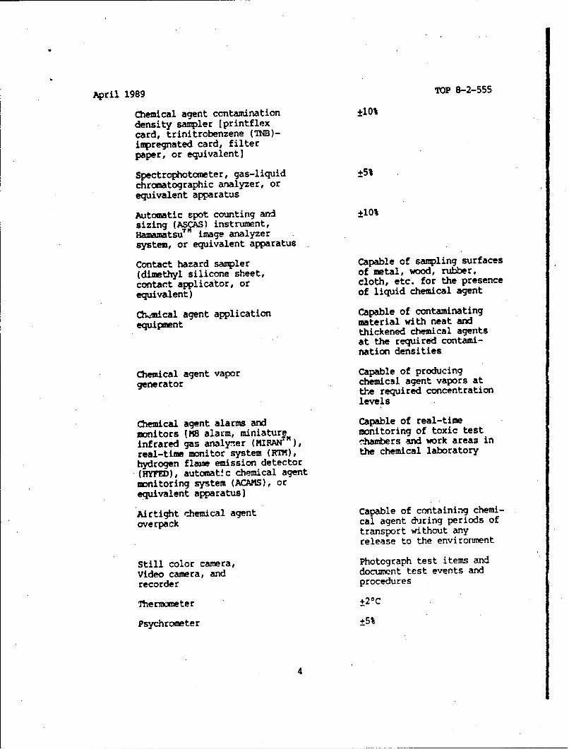
Chemical agent ccntamination ±10%density sampler (printflexcard, trinitrobenzene (TNB)-impregnated card, filterpaper, or equivalent)
Spectrophotometer, gas-liquid ±5%chromatographic analyzer, orequivalent apparatus
Automatic spot counting and +10%sizing (ASCAS) instrument,Hamamatsu!" image analyzersystem, or equivalent apparatus
Contact hazard sampler Capable of sampling surfaces(dimethyl silicone sheet, of metal, wood, rubber,contact applicator, or cloth, etc. for the presenceequivalent) of liquid chemical agent
Chmical agent application Capable of contaminatingequipment material with neat and
thickened chemical agentsat the required contami-nation densities
Chemical agent vapor Capable of producinggenerator chemical agent vapors at
the required concentrationlevels
Chemical agent alarms and Capable of real-timemonitors IM8 alarm, miniature monitoring of toxic testinfrared gas analyzer (MIRANT"), .Jhambers and work areas inreal-time monitor system (RTM), the chemical laboratoryhydrogen flame emission detector(HYFED), autcmat. c chemical agentmonitoring system (ACAMS), orequivalent apparatus)
Airtight chemical agent Capable of containing chemi-overpack cal agent during periods of
transport without anyrelease to the environment
Still, color camera, Photograph test items and
Video camera, and document test events and
recorder procedures
Thermometer +20C
Psychrometer +5%
4

April 1989 TOP 8-2-555
Rough handling test and As specifie? inenvironmental chamber MIL-STD-810instruments
Microsyringe ±0.5 UL
Equipment required for As specified in TOPsizing, dispensing, 8-2-111measuring density of,and decontaminatingzinc sulfide fluorescentparticles (FP)
Airdrop delivery test As specified in TOP
instruments 7-2-509
3. PREPARATION FOR TEST.
3.1 Project Officer.
The project officer will be responsible for all phases of test planning,coordinating, conducting, and reporting.
3.2 Documentation.
The project officer will ensure that the following are available at thework site:
a. Independcnt assessment plan (IAP)..
b. Approved detailed test plan (DTP).
c. Approved operations plan (OPLAN).
d. Safety assessment report (SAR).
e. Office of the Surgeon General health hazards assessment report (HHAR).
f. Funding document.
g. Basic issue item list (BIIL).
h. System support package (SSP) list.
i. Environmental impact assessment for life cycle (EIALC).
j. Record of envircnmental consideration iREC), or environmental assess-ment (EA) with a finding of no significant imvpact (FNSI), or environmentalimpact statement (EIS) (as necessary).
k. Standing operating procedures (SOPs).
I5

April 1989 TOP 8-2-555
3.3 Project Logbook, Project File, and Checklist.The project officer will establish and maintain a project logbook, project
file, and checklist as described in U.S. Army Test and Evaluation Command(TECOt) Pamphlet 70-3.
3.4 Familiarization.
The project officer will ensure that test participants are thoroughlyfamiliar with items to be tested, test procedures, support and test equipment,test measurement and diagnostic equipment (TMDE), repair parts and specialtools (RPST), precautions to be observed, technical manuals (Tms), and otherpertinent government and manufacturer publications. The project officer willensure that new equipment training (NET) is provided by the developer, asnecessary.
3.5 Safet2~
3.5.1 Safety Assessment Report (SAR).
Before a test is started, the project officer will ensure that a SAR hasbeen received from the developer and is understood. The SAR must includeinformation about operational limitations and hazards peculiar to the testitem. The SAR should include the Office of the Surgeon General's HHAR. Ifthe SAR is not received or is inadequate, testing will be deferred until thematter is resolved.
3.5.2 Safety.
The project officer will ensure that test operations will be conducted insuch a manner that test participants and nearby persons, property, and equip-ment will not be exposed to safety or health hazards beyond normal duty limits.All safety regulations, safety directives, safety requirements, and SOPs per-taining to the test item will be followed. Basic informa~Aon on industrial,range, and chemical agent safety 0s inc)uded ip AR 385-10 , U.S. Army MaterielCommand (AMC) Regulations 385-100 and 385-131 • U.S. Army Dugway ProvingGround (DPG) Regulation 385-1' and TOP 8-2-553
A safety officer will be responsible for the safety aspects of the test.The safety officer will be familiar with test item construction and operationand critical components. Before the start of testing, a safety inspectionwill be conducted by the safety officer and test personnel to identifypotential safety and health hazards. The safety officer will also review testprocedures for analyzing safety and health hazards and recomnending controlmeasures.
Each test participant will be informed of potential safety and healthhazards involved, and the precautions required to prevent accidents and agentexposures.
6

April 1989 TOP 8-2-555
3.5.3 System Safety Verification.
A syster I safety verification program, conducted in accordance with (IMW)TOP 1-1-060 , is required to ensure that adequate testing is conducted toprovide safety and health analysis of the system. This verification is theprocess by which systems that are to be fielded are tested and analyzed toensure that they can be safely operated and mjntained by field troops withoutcompromising mission requirements. AR 385-16 describes the safety verifi-cation program and lists the requirements that must be met.
3.5.4 Safety Equipment.
The project officer will determine the type of safety equipment and levelof protective clothing needed for each test procedure. The project officerwill also ensure that the required quantities of each type of materiel areavailable and that materiel handling devics meet the standards of theOccupational Safety and Health Act (OSHA)
3.5.5 Disposal Instructions.
The project officer will ensure the availability of approved proceduresand equipment for disposal of damaged, corrosive, or toxic materials. Basicguidanc? for disposal of chemical agent-exposed materiel is in AMC Regulation385-131
3.6 Instrumentation.
The project officer will ensure that all instruments ysed for data acqui-sition are calibrated or certified for use IAW AR 750-25
3.7 Envi ronmental Assessment.
In compliance with the National Environmental Policy Act (NEPA), theDepartment of the Army (DA) requires that an EIALC be prepared and thatpotential environmental impacts be assessed at the earliest practical stage inthe planning process of any new system. Test execution at TECOM agencies mustalso be assessed for environmental impact. To prepare the necessary environ-menta documentati on, refr to AMC Supplement 1 and TECOM Supplement 1 to AR200-2 '. First, evaluate the proposed test and materials against the criteriafor categorical exclusion frcm assessment documentation. If categoricalexclusion is possible, work with the installation envirormental coordinator toprepare and file the REC. If the test activities are not categoricallyexcluded, work with the installation environmental coordinator in preparing anEA. The outcome of the EA will indicate whether the test activity will resultin significant or insignificant impact. If insignificant impact would result,prepare an appropriate FNSi for local publication and filing before testing.If significant impact would result, a full EIS must be prepared. Preparationof an L.7S is complex and time consuming. Consult the installation environ-mental coordinator because state agencies, the U.S. Environmental Protection"Agency, ard interested/affected public groups will become involved duringcomiment periods built into the EIS approval cycle.
7

April 1989 TOP 8-2-555
3.8 Security.
If classified information or materiel is involved in the test program, theproject officer will ensure that all test participants have current securityclearances, test and storage areas have adequate physical protection, anddocument containers meet required standards (see publications in the AR 380and AR 539 series).
3.9 Surety.
The project officer will ensure that all test participants are currentlyenrolled in the Chemical Personnel Reliability Proqram (CPRP), that medicalrequirements are met, and that the DTP and OPLAN address all surety aspectsIAW regulatory requirements (see publications in the AR 50 series).
3.10 Logistics.
The project officer will review the DTP to establish support require-ments and ensure that test supplies and equipment are available in sufficientquantities to support the test. The project officer will carry out timelyscheduling to ensure that facilities and instruments are available for eachtest.
4. TFST CCNTROLS.
4.1 General.
Tests will be conducted in optimum sequence to make the most cost-effective and timely use of facilities, equipment, instruments, and people.The sequence of tests will be based upon a continual risk analysis and anestimate of those conditions under which it is suspected that the test itemmay not perform satisfactorily. High risk tests will be performed at theearliest practical stage.
4.2 Safety.
4.2.1 Documentation.
SOPs and OPLANs for all hazardous operations will be approved by theinstall~tion commander or his designated representative IAM AM(C Regulation385-100
4.2.2 Cperational Readiness Inspection (OR!).
An ORI will be performed before conduct of any test involving lethal orincapacitating chemical agents or other hazardous operations. The ORI willconsist of a complete trial, using all procedures as if agent were present oihazardous operations w&re being undertaken. The installation commander willbe briefed on the results of the ORI.
8

April 1989 TOP 8-2-555
4.2.3 Equipe nt Operat on and Support Hazard Analyses.
Operation and suppo t hazard aralyses will be performed during testing toidentify hazards associ ted with the test item, support equipment, and proce-dures. The results of ,azard analyses, accident investigations, inspections,interviews, and test int:idence reports (TIRs) of unsafe conditions will be usedas methods for accunmlating data. The project officer and test safety officerwill analyze the data b using the risk analysis procedures in MIL-STD-882Aý6.
4.2.4 Decontamination.
Facilities, test it ms, and equipment contaminated with chemical agentduring testing will be lecontaminated IAW the procedures in AMC Regulation385-131 . Procedures (for decontaminating facilities, test items, and equipj-ment contaminated with :hemical agent) not covered in AMC Regulation 385-131will be performed iAW p oposals made by the Chemical Laboratory Division andapproved by the Safety ¶ffice.
4.3 Test Chamber Operating Conditions.i
The DTP and OPLAN wil specify the operational limitations for storage andenvironmental chambers, including range and accuracy requirements for temper-ature, relative humidity , wind velojity, solar radiation, and other parametersspecified in AR 70-38 , MIL-STD-810 , and applicable TOPs. For laboratorytests performed to dete nmine detector kit agent sensitivity capabilities, theDTP, OPLAN, and SOPs will specify the range and accuracy requirements foLlaboratory hood temperature and relative humidity and the accuracy require-ments for the various p4ysical and chemical properties of specified chemicalagents.
4.4 Human Factors Engi eering (HFE) Tests.
HFE tests will incl~de the use of soldier/operator, maintainer, tester,and evaluator (SrMTE) personnel to provide data and iiiformation for the HFEtest and analysis. Selection of SOMTE personnel for test participation willbe based on primary military occupational specialty (PMOS) qualifications,experience, and skill levels. specific criteria for selecting SCMTE personnelwill be stated in the DTP and OPLAN.
4.5 Test Item History and Maintenance Data.
A logbook will be prepared for recording test item histories, includingstorage time and ronditions, and all appropriate information concerning theenvironmental and test conditions within which the test item is used. Inaddition, a maintenance log will be prepared to record all maintenance andservice. actions performed during the tost. The maintenance log will be pre-pared •d used LAW the ýrequirements of TECOM Supplement 1 to AMC Regulation700-15
9

April 1989 TOP 8-2-555
-5. mm RMANCE TESTS.
5.1 Receipt Inspection.
5.1.1 Method.
ReceiptI inspection will be performed IAW the applicable instructions inTOP 8-2-500 . All shipping containers will be irspected for damage, looseclosures, correct and legible markings, and the presence of unpacking emstorage instructions. Defects will be documented by TIRs and photographed(with metric scale), when applicable. All shipping containers, except thosedesigrated for use in the accelerated packaged storage and sequential roughhandling test (Paragraph 5.5) and the airdrop delivery test (Paragraph 5.9),will be opened. The type and condition of the blocking, bracing, and cushion-ing material -ill be recorded.
Individual detector kits will, be inspected for the following conditions:
a. Correct and legible identification mu~rkings.
b. An expiration date that cotresponds with the shortest shelf life ofany kit component.
c. Legible instructions.
d. All ccmponents present and 'individually identified.
e. Required vapor barrier bags for kit couponents present and sealed.
f. Defects, such as missing ccmponents, incorrect or missing identi-fication markings, broken ampoules, spillage, shortar's, and damaged vaporbarrier bags (holes, cuts, tears, and punctures).
Defects will be documented by TIRs and photographed (with -etric scale),iewn applicable. Detector kits that are judged to be so damaged that troopsin the field would not use them will be reim~ved from further testing. Thetemaining kits will be serial-numbered and the test identification and mnu-facturer serial numbers recorded. A minimna 3f 15 detector kits will berandomly selected and measured for conformance to the size and weight speci-fications. Consult statistician for guidance on valid randcm selection ofdetector kits.
5.1.2 Data Required.
The following data are required:
a. Shipping container:
(1) Type of material (wood, fiberboard, etc.).
(2) Means of closure (tape, metal bands, etc.).
10

April 1989 TOP 8-2-555
(3) Markings (present or absent).
(4) Marking legibility.
(5) Unpacking instructions (present or absent).
(6) Storage instructions (present or absent).
(7) Evidence of damage. Photographs, with metric scale, will betaken when necessary to clarify descriptions.
(8) Type and condition of blocking, bracing, and cushioning material.
(9) Number of intermediate packages.
b. Detector kit:
(1) Correct identification markirgs (present or absent).
(2) Marking legibility.
(3) Expiration date on components.
(4) Correct expiration date on kit (present or absent).
(5) Operating instructions (present or absent).
(6) Legible operating instructions.
(7) Results of inventory.
(8) Markings on kit components (present or absent).
(9) Legibility of markings on kit components.
(10) Required vapor barrier bags (present or absent; sealed orunsealed).
(11) Evidence of defects. Photographs, with metric scale, will betaken when necessary to clarify descriptions.
(12) Weights and dimensions of measured kits.
(13) A list of test identification serial numbers with correspondingmanufacturer serial numbers.
3.2 Safety Analysis.
5.2.1 Method.
5.2.1.1 Safety Analysis. The detector kit and components will be inspectedto ensure compliance wi the provisions outlined in the developer's SAR and
11

April 1989 TOP 8-2-555
that all hazards identified in the SKI have been eliminated or controlled/mitigated to a•, acceptable level. ThE requirements of the Office of theSurgeon General HHAR will be assessed IAW AR 40-10".
3.2.1.2 Test Item inspection. The detector kit and components will beexamined for any defect, omission, or condition that could be detrimental touser safety. Warnings, cautions, and procedires in the IM, on the operationinstruction cards, and on test items will be examined, to ensure that they areconspicuous and adequate to minimize operational and maintenance hazards.
5.2.1.3 Safety Release Information. A recommendation for a safety releasewill be prepared and submitted to TECOM Headqparters, Aberdeen Proving Ground,Maryland, LAW TECCM Supplement 1 to AR 385-16 at the completion of theoperator training and familiarization test (Paragraph 5.3).
5.2.2 Data Required.
a. Developer's SAR.
b. Office of the Surgeon General's HHAR, if not included in the SAR.
c. A detailed description of each safety and health hazard identifiedduring any test will be presented with the approprif~e hazard severity andprobability of occurrence category IAW MIL-STD-88ZA . Photographs, withmetric scale, will accompany the hazard description as necessary to clarifythe nature of the hazard.
d. Findings related to the adequacy of existing safety and warningdevices, or the need for additional or improved safety or warning devices.
e. Findings related to the adequacy of safety instructions, with recom-mendations for changes or additions.
5.3 operator Training and Familiarization.
5.3.1 Method.
5,3.1.1 New'Equipent Training. (NET). NET will be given to SCMTE personnelwho have been certified by a medical authority to be physically fit and tohave normal vision and normal color peryption. NET will be performed IAM theapplicable instructions of TOP 10-2-501 and the following guidance:
a. NET will be provided by the developer. Training will include safetyinstructions, operating instructions for the detector kit and the Simulator,Detector Tickets, Chemical Agent: Training M256 (TRAINS) during daylight andnight conditions, operations with CB protective and arctic clothing, care(maintenance and decontamination), and storage.
b. Copies of the draft Th and written safety and operating instructionswill be given to each test participant.
12

April 1989 TOP 8-2-555
c. Initial training will be conducted with TRAINS, using chcmical agentsimulants. The project officer will verify that each test participant canperform all required operations with TRAINS before proceeding to operationswith the detector kit.
5.3.1.2 Operations with the Detector Kit.
a. Each test participant *ill perform all of the detector kit positiveand negative agent sensitivity tests. Blanks (samplers with no chemical agentor with a blank level of chemical agent present) will be used in the negativeresponse tests. (NOTE: Blank levels are defined in Paragraph 5.4.1.1.) Eachtest participant will perform every test during daylight and night cnditionsat standard ambient temperature (25+10 0 C), as defined by MIL-STD-810 , and atthe extreme tempera-ure (-31*C) for the basic cold CDT of AR 70-38 . Whileperforming tests at standard ambient temperature, test participants will weara standard CB protective mask, hood, gloves, and overgarment. While performingtests at the extreme basic cold temperature, test participants will wear arcticclothing with the standard CB protective mask, hood, impermeable glove liners,and overgarment.
b. The project officer will verify that each test participant under-stands the instructions, can perform the required kit operations, and cancorrectly interpret the test results.
5.3.1.3 Maintenance and Decontamination. Test participants will be trainedin the methods of 1taintenance-Tiifapiable) and decontamination in the draftTh. During the NBC contamination survivability test (Paragraph 5.8) and thelogistic supportability test (Paragraph 5.11), these test participants willperf.rm maintenance tasks and decontamination using the methods providedduring training. Observations and measurements obtained during these testswill be used to evaluate the adequacy of the methods and training.
5.3.1.4 Questionnaire and Interviewi. At the end of this test, test partici-pants will-be asked a series of questions designed to provide information onthe adequacy of the NET and the TM, the readability of the instructions byperson wearing a CB protective mask, compatibility with CB protective andarctic clothing, and the ease of handling kit components, performing tests,and interpreting test results. The questionnaire •Nd interviews will beprepared and administered IAW TECOM Pamphlet 602-1
5.3.2 Data Required.
a. Comments on each of the following aspects of operator training andfamiliarization:
(1) Adequacy of NET.
(2) Suitability of the draft TM for training.
(3) Accuracy, completeness, and clarity of the draft TM and thedetector kit and TRAINS operating instructions.
13

April 1989 TOP 8-2-555
(4) Readability of detector kit and TRAINS operating instructioncards, while operator is wearing a CB protective mask.
(5) Compatibility of detector kit and TRAINS with CB protective andarctic clothing.
(6) Ease of handling kit samplers, performing tests, and interpretingresults.
(7) Use of detector kit and TRAINS at night.
(8) Use of detector kit and TRAINS at basic cold temperature.
(9) Adequacy of maintenance and decontamination instructions andprocedures.
b. Identification of procedural errors, if applicable.
c. Identification of incipient operator errors, if applicable.
d. Suggested imprcvements.
e. Time required to perform each sensitivity test during daylight andnight conditions at standard ambient and basic cold temperatures.
5.4 Initial Performance.
5.4.1 Method.
5.4.1.1 Test Conditions. Initial performance (control) tests of untreateddetector kits will be performed to determine if the detector kit samplers willrespond correctly to the specified chemical agents at the required minimumconcentration/density level within the required maximum time (see Appendix Bfor failure definitions). Every test for which the kit provides a detectioncapability will be performed with each assigned detector kit during day andnight conditions and at each of the CDT test conditions in Table 1. A blanklevel of chemical agent will be established. The blank level is the level ofagent that may be present but will not cause the kit sampler to indicate apositive determination. If the requirements document or IAP does not specifya blank level, the following will be used:
a. For water tests, the blank level equals 0.8 times the maximum permis-sible level specified in Technical Bulletin - Medical (TB MED) 577" for thelong-term water quality standard.
b. For tests intended to provide an unmask indicator, the blank levelequals 0.9 times the U.S. Army Nuclear-Che:,4cal Agency (USANCA), Springfield,Virginia, negligible risk level in mg-min/Wr divided by 720 b
c. For all other tests, the blank level equals 0.5 times the minimumdetectable level specified in the requirements document.
14

April 1989 TOP 8-2-555
Table 1. Climatic Design Types and Test Conditions for Initial PerformanceTest of Chemical Agent Detector Kits.
Climatic Design Type Operation Test Conditions
Standard ambient temperaturea 25_100C
Basic cold6 As described in MIL-STD>-810,Method 502.2, Procedure II,-31C.c
Basic hot 6 As described in MIL-STD 810,Method 501.2, Procedure II, Table501.2-1 Ynduced.c
variable high hbiudit9 As described in MIL-STD-810,Method 507.2, Procedure II, Table507.2-1, Cycle 3.c
":As defined in MTu-STD-810. 2
6 Reference 1.CReference 2.
NOTE: At least 50 percent of the blank tests will be done at the blanklevel. The remainder will be done with no agent present.
The number of replicate trials to be performed for positive (agent) andnegative (blank) response tests for each agent/sample type/C[tT test conditioncombination (e.g., nerve agent vapor tested at basic cold conditions) will bedetermined frcu the specified reliability and confidence level requirements.
An operator and an observer will be used. The operator, who may be acivilian employee, will operate the kit and laboratory equipment used in thetest. The operator will know the true response of the test (positive ornegative). SCMTE personnel will serve as observers. The observer will maketest determinations under conditions that represent expected field conditionsto the extent this is practicable in the laboratory. The observer will notknow the true response of the test. The duty of the observer will be rotatedamong a representative group of soldiers.
5.4.1.2 Test Hoods. Agent challenge tests will be conducted inside charcoal-filtered laboratoy hoods with transparent facings. The hoods are constructedto contain chemical agent during testing and to pass contaminated air througha certified filter system before release to the atmosphere. A separate hoodwill be used for each type of agent; however, if the kit is structured so thatmore than one agent is detectable with each sampler, then all agent and blanktests will be performed in one hood. The temperature and relative humidity of
15

April 1989 TOP 8-2-555
the atmosphere within the chamber will be controlled. Agent vapor concentra-tion, agent concentration in water, and contamination density will be control-led within the specified limits for the minimum detection concentration/density levels. Laboratory control samples will be taken and analyzed withappropriate laboratory instruments (Paragraph 2.2) to ensure that the agentconcentration/density is within the specified limits.
5.4.1.3 Pretest Inspection. The samplers will be removed from the detectorkit, unpackaged (if required), and inspected. A trained observer will performthe inspection. Samplers will be examined for physical and mechanical defectsthat would render the samplers incapable of making valid tests for thepresence or absence of chemical agent. Examples of defects that would renderthe samplers unusable are missing components, broken ampoules, and obstructedreagent passageways. The time required to perform the inspection and thenumber and type of samplers inspected will be recorded.
5.4.1.4 Sampler Response Test. The samplers will be prepared for agentexposure IAW the kit operating instructions. The vapor samplers will beinserted in the appropriate chamber and exposed to agent for the requiredtime. Surface contact samplers and samplers used to detect chemical agent inwater will be operated in the test chamber IAM the kit instructions. Blanks(samplers with no agent or with the blank level of agent present) will beprocessed under the same temperature and humidity conditions as samplers withagent present. Total processing time will be recorded for each positive(agent) and negative (blank) response test.
NOTE: For vapor, water, and material samples contaminated with chemicalagent and exposed to basic cold test conditions, additional timemay be reruired to heat the water, materials, and samplers beforeperforming the agent sensitivity tests.
5.4.1.5 Response Analysis. ."he response of each sampler will be independ-ently read and recordedby the operator and an observer. Both persons willhave been trained IAM the procedures in Paragraph 5.3. Using the kit instruc-tions, the operator and observer will classify the responses as positive,negative, or uncertain. Background light conditions in the laboratory will bemeasured and recorded periodically during operations under day and night con-ditions. The time required to analyze each response will be recorded foroperator and observer.
NMTE: Kit instructions may specify the use of a light sotrce for responseanalysis under night conditions. In that event, light conditionswill be determined within 1 m of the sampler.
5.4.2 Data ReLuirpd.
a. Detector kit and sampler identification numbers.
b. Test conditions: (1) CDT test conditions; (2) agent; (3) agentconcentration in vapor or water, or agent contamination density on materialsurface; and (4) type of material (wood, soil, concrete, glass, etc.), ifapplicable.
16

April 1989 TOP 8-2-555
c. Sampler inspection times.
d. Descriptions of all observed sampler defects. Photographs, withmetric scale, will be provided if necessary to clarify descriptions.
e. Light conditions (daylight or night) and luminance (light source) data.
f. Sampler exposure times.
g. Operator and observer response analyses (positive, negative, oruncertain).
h. Operator and observer response analysis times.
i. True analyses (positive or negative).
J. Category of operator and observer response analyses (correct, chemicalfailure, physical failure, or operational failure).
k. Color photographs, with metric scale, of typical sanpler responses.
1. Laboratory control data.
5.5 Accelerated Packaged Storage and Sequential Rough Handling.
5.5.1 Method.
a. This test will determine the capability of the packaged test item towithstand the combined effects of accelerated packaged storage and sequentialrough handling in CDT 'basic. The, accelerated storage test will expose thepackaged detector kit to higher and lower temperatures than it is expected toexperience in actual packaged storage. Coordination should be made with thedeveloper to ensure that the detector kit will endure these temperatures andto determine if a different shelf-life test is more appropriate.
b. Analysis will be on an indicative basis only. Success or failure inthe accelerated packaged storage test does not conclusively indicate that thepackaged detector kit has or does not have the specified storage life.
c. The sequential rough handling tests simulate transportation to a unitafter depot storage.
5.5.1.1 Accelerated Packaged Storage Test. Three level-A shipping containersof packaged test items willbe-useduinthis test. One shipping container willbe subjected to 12 weeks of accelerated basic cold storage conditions, oneshipping container to 12 weeks of accelerated basic hot storage conditions,and one shipping container to 12 weeks of accelerated variable high humiiitystorage conditions. The storage conditions are described in MIL-STD-810 asfollows:
17

April 1989 TOP 8-2-555
a. Basic cold: Method 302.2, Procedure I, -31*C.
b. Basic hot: Method 501.2, Procedure I.
c. Variable high humidity: Method 507.2, Procedure II, Table 507.2-I,Cycle 3.
After completion of the packaged storage test, the-detector kits in eachshipping container will be inspected for damage. A random sample (approxi-mately one-fourth) of the undamaged kits in each container will be removed andreplaced with dummy packages. Damaged detector kits will also be replacedwith dummy packages. The undamaged detector kits removed from the containerswill be tested for chemical agent sensitivity IAW Paragraph 5.4.1 and TableA.1.
5.5.1.2 Sequential Rough Handling Tests. The three shipping containers willbe subjected to the following Sequential rough handling tests, performed IAWthe indicated methods:
a. Low pressure (altitude): MIL-STD-810, Method 500.2, Procedure T2.
b, Vibration: MIL-STD-810, Method 514.3, Category 3 (loose cargo trans-port)
Ic. Shock: MIL-STD-810, Method 516.3, Procedure IV2 .
For test item- subjected to basic cold, basic hot, and variable highhumidity storage conditions, the vibration and shock tests will be conductedunder the conditi.ons shown in Table 2.
After completion of the law pressure test, the detector kits in eachshipping container will be inspected for damage. A random sample (approxi-mately one-fourth) of the undamaged detector kits in each shipping containerwill be removed and replaced with dummy packages. Damaged detector kits willalso be replaced with dummy packages. The undamaged detector kits removedfrom the container will be tested for chemical age'lt sensitivity IAW Paragraph5.4.1 and Table A.l. After the vibration test, aL detector kits will beinspected for damage. A random sample (approximatelv one-fourth) of theundamaged detector kits from each shipping container will be tested forchemical agent sensitivity IAW Paragraph 5.4.1 and Table A.I.
The remaining detector kits will be subjected to the shock test in theunpackaged configuration. The drop height will be- 1.5 m, unless otherwisespecified in the DTP. After the shock test, all Jetrptor kits will beinspected for damage. Undamaged detector kits will be tested for chemicalagent sensitivity IAW Paragraph 5.4.1 and Table A.I.
5.5.2 Data Required.
a. Test item identification numbers and record of treatment(s) for eachdetector kit.
18

April 1989 TOP 8-2-555
Table 2. Test. Conditions for Vibration and Shock Tests.
Test Item Storage Conditions Vibration and Shock Test Conditions
Basic cold MIL-STD-810, Method 502.2, Procedure I,
-310C.
Basic hot MIL-STD-810, Method 502.2, Procedure 1.a
Variable high humidity MIL-STD-810, Method 507.2, Procedure It,Table 507.2-I, Cycle 3.4
a Reference 2.
b. Temperature versus time data for basic cold, basic hot, and variablehigh humidity tests.
c. Relative humidity versus time data for basic cold, basic hot, andvariable high humidity tests, if applicable.
d. Low pressure test chamber data:
(1) Pressure versus time data.
(2) Temperature versus time data.
e. Vibration test data:
(1) Descriptions of test apparatus and test fixture.
(2) Vibration spectrum and intensity.
(3) Duration of exposure.
(4) Axes of exposure.
(5) Location of accelerometers.
(6) Temperature/relative humidity versus time data.
f. Shock, test data:
(1) Description of drop tester.
(2) Height of the drops.
19

April. 1989 TOP 8-2-555
(3) Number of drops per detector kit.
(4) Drop surface (face, edge, or corner) for each drop.
g. Results of package inspection.
h. Descriptions of damage. Photographs, with metric scale, will beprovided if necessary to clarify descriptions.
i. Detector kit sampler inspection times.
j. Descriptions of all observed sampler defects. Photographs, withmetric scale, will be provided if necessary to clarify descriptions.
k. Chemical agent sensitivity test conditions: (1) CDT test conditions;(2) agent type; (3) agent concentration in vapor or water, or agent contami-nation density on material surface; and (4) type of material (wood, soil,concrete, glass, etc.), if applicable.
1. Sampler exposure times.
m. Operator and observer response analyses (positive, negative, oruncertain).
n. Operator and observer response analysis times.
o. True analyses (positive or negative).
p. Category of operator and observer response analysis (correct, chemicalfailure, physical failure, or operational failure).
q. Laboratory control data.
5.6 Adverse Environments.
5.6.1 Method.
Determine the capability of the detector kit to withstand the effects ofadverse envirorments by performing the tests listed in Table 3.
After each test, perform detector kit sampler inspection and chemicalagent sensitivity tests lAW Paragraph 5.4.1 and Table A.1.
5.6.2 Data Required.
5.6.2.1 Low Pressure (Altitude Test).
a. Detector kit identification numbers.
b. Chamber pressure versus time data.
c. Chamber temperature versus time data.
20

April 1989 TOP 8-2-555.
Table 3. Test Methods, Number of Detector Kits, and Package Configurationsfor Adverse Environment Test of Chemical Agent Detector Kits.
Test Method Number ofAdverse (Procedures and Methods Items to be Package
Environment from MIL-STD-810)' Tested Configuration
High Temperatureb Method 501.2, Procedure I,Table 501.2-II Induced 5 Packaged
High Temperature Method 501.2, Procedure I,Table 501.2-II Ambient LUnpackaged
Low Temperatureb Method 502.2, Procedure I,-310C 5 Packaged
Low Temperature Method 502.2, Procedure I,
-31VC 5 Unpackaged
Temperature Shock Method 503.2, Procedure 1 5 Uripackaged
Solar Radiation Method 505.2, Procedure II 5 Unpackaged
Rain Method 506.2, Procedure I 5 Unpackaged
Humidity" Method 507.2, Procedure 1,
Table 507.2-I, Cycle 3 5 Unpackaged
Fungus Method 508.3, Procedure I 5 Unpackaged
Salt Fog Method 509.2, Procedure I 5 Unpackaged
Sand and Dust Method 510.2, Procedures Iand II 5 Unpackaged
Leakage Method 512.2, Procedure I 5 Unpackaged
:Reference 2.These tests may be omitted if the basic hot, basic cold, and variable highhumidity tests of Paragraph 5.5.1 were successfully completed.
d. Results of inspection of detector kits.
e. Detector kit sampler inspection times.
f. Descriptions of all observed sampler defects. Photographz, withmetric scale, will be provided if necessary to clarify descriptions.
21

April 1989 TOP 8-2-555
g. Chemical agent sensitivity test conditions: (1) CDT test conditions;(2) agent type; (3) agent concentration in vapor or water, or agent contami-nation density on material surface; and (4) type of material (wood, soil,concrete, glass, etc.), if applicable.
h. Sampler exposure times.
i.. Operator and observer response analyses (positive, negative, oruncertain).
J. Operator and observer response analysis times.
k. True analyses (positive or negative).
1. Category of operator and observer response analyses (correct, chemicalfailure, physical failure, or operational failure).
a. Laboratory control data.
5.6.2.2 High Temperature Test.
a. Detector kit identification numbers.
b. Packaging (present or absent).
c. Chamber temperature versus time data.
d. Chamber relative humidity versus time data, if applicable.
e. Results of inspection of detector kits and packages.
f. Detector kit sampler inspection times.
g. Descriptions of all observed sampler defects. Photographs, withmetric scale, will be provided if necessary to clarify descriptions.
h. Chemical agent sensitivity test conditions: (1) CDT test conditions;(2) agent type; (3)-agent concentration in vapor or water, or agent contami-nation density on material surface; and (4) type of material (wood, soil,concrete, glass, etc.), if applicable.
i. Sampler exposure times.
J. Operator and observer response analyses (positive, negative, oruncertain).
k. Operator and observer response analysis times.
1. True analyses (positive or negative).
m. Category of operator and observer response analyses (correct, chemicalfailure, physical fai.ure, or operational failure).
22

April 1989 TOP 8-2-555
n. Laboratory control data.
5.6.2.3 Low Temperature Test. Same as Paragraph 5.6.2.2.
5.6.2.4 Temperature Shock Test.
a. Detector kit identification numbers.
b. High and low temperature chamber test data and test item responsetemperatures.
c. Duration of each test.
d. Transfer times.
e. Results of inspection of detector kits.
f. Detector kit sampler inspection times.
g. Descriptions of all observed sampler detects. Photographs, withmetric scale, ;&ill be provided if necessary to clarify descriptions.
h. Chemical ageit sensitivity test conditions: (1) CDT test conditions;(2) agent; (3) agent concentration ir vapor or water, or agent contaminationdensity on material surface; and (4) type of material (wood, soil, concrete,glass, etc.), if applicable.
i. Sampler exposure times.
J. Operator and observer response analyses (positive, negative, oruncertain).
k. Operator and observer response analysis times.
1. True analyses (positive or negative).
a. Category of operator and observer response analyses (correct, chemicalfailure, physical failure, or operational failure).
n. Laboratory control data.
5.6.2.5 Solar Radiation Test.
a. Detector kit identification numbers.
b. Location of temperature sensors on detector kits.
c. Temperature versus time data for each cycle.
d. Solar lamp bank identification data.
e. Results of inspection of detector kits.
23

April 1989 TOP 8-2-555
f. Detector kit sampler inspection times.
g. Descriptions of all observed sampler defects. Photographs, withmetric scale, will be provided if necessary to clarify descriptions.
h. Chemical agent sensitivity test conditions: (1) CDT test conditions;(2) agent; (3) agent concentration in vapor or water, or agent contaminationdensity on material surface; and (4) type of material (wood, soil, concrete,glass, etc.), if applicable.
i. Sampler exposure times.
j. Operator and observer response analyses (positive, negative, oruncertain).
k. Operator and observer response analysis times.
1. True analyses (positive or negative).
m.. Category of operator and observer response analyses (correct, chemicalfailure, physical failure, or operational failure).
n. Laboratory control data.
5.6.2.6 Rain Test.
a. Detector kit identification numbirs.
b. Exposure durations of test item surfaces.
c. Rainfall rate.
-d. wind velocity.
e. Water and test item temperatures.
f. Surfaces of detector kits subjected to rainfall.
g. Results of inspection of detector kit inner surfaces and componentsfor water penetration and corrosion.
h. Detector kit sampler inspection times.
i. Descriptions of all observed sampler defects. Photographs, withmetric scale, will be provided if necessary to clarify descriptions.
J. Chemical agent sensitivity test conditions: (1) CDT test conditions;(2) agent; (3) agent concentration in vapor or water, or agent contaminationdensity on material surface; and (4) type of material (wood, soil, concrete,glass, etc.), if applicable.
24

April 1989 TOP 8-2-555
k. Sampler exposure times.
1. Operator and observer response analyses (positive, negative, oruncertain).
m. Operator and observer response analysis times.
n. True analyses (positive or negative).
o. Category of operator and observer response analyses (correct, chemicalfailure, physical failure, or operational failure).
p. Laboratory control data.
5.6.2.7 Humidity Test.
a. Detector kit identification numbers.
b. Relative humidity versus time data.
c. Temperature versus time data.
d. Results of inspection of detector kit inner surfaces and componentsfor water penetration and corrosion.
e. Detector kit sampler inspection times.
f. Descriptions of all observed sampler defects. Photographs, withmetric scale, will be provided if necessary to clarify descriptions.
g. Chemical agent sensitivity test conditions: (1) CDT test conditions;(2) agent; (3) agent concentration in vapor or -water, or agent contaminationdensity on material surface; and (4) type of material (wood, soil, concrete,glass, etc.), if applicable.
h. Sampler exposure times.
i. Operator and observer response analyses (positive, negative, oruncertain).
J. Operator and observer response analysis times.
k. True analyses (positive or negative).
1. Category of operator and observer response analyses (correct, chemicalfailure, physical failure, or operational failure).
m. Laboratory control data.
5.6.2.8 Fungus Test.
a. Detector kit identification numbers and orientations.
25

April 1989 TOP 8-2-555
b. Types of fungi (genus, species, and any other appropriate identifi-cation).
c.. Evidence of fungal growth at the end of 7 days of exposure and at theend of the test.
d. Location of fungi.
e. Description of growth, including colors, area covered, growth.patterns, density of growth, and thickness of growth. Photographs, withmetric scale, will be provided if necessary to clarify description.
f. Test duration.
g. Data and observations related to effects of fungal growth (refer toMIL-STD-810, Method 508.32).
h. Chamber relative humidity versus time data.
i. Chamber temperature versus time data.
J. Chamber air velocity versus time data.
k. Results of inspection of detector kit inner surfaces and componentsfor fungal growth, corrosion, and deterioration,
1. Detector kit sampler inspection times.
a. Descriptions of all observed sampler defects. Photographs, withmetric scale, will be provided if necessary to clarify descriptions.
n. Chemical agent sensitivity test conditi'ns: (1) CDT test conditions;(2) agent; (3) agent concentration in vapor or water, or agent contaminationdensity on material surface; and (4) type of material (wood, soil, concrete,glass, etc.), if applicable.
o. Sampler exposure times.
p. Operator and observer response analyses (positive, negative, oruncertain).
q. Operator and observer response analysis times.
r. True analyses (positive or negative).
s. Category of operator and observer response analyses (correct, chemicalfailure, physical failure, or operational failure).
t. Laboratory control data.
26

April 1989 TOP 8-2-555
5.6.2.9 Salt Fog Test.
a. Detector kit identification numbers and orientations.
b. Test duration or cycling schedule.
c. Chamber temperature versus time data.
d. Salt solution concentration.
e. Salt solution pH.
f. Salt solution specific gravity.
g. Salt solution fallout rate.
h. Type of water and resistance of initial water.
i. Results of inspection of detector kit inner surfaces and componentsfor water penetration, corrosion, and deterioration.
J. Detector kit sampler inspection times.
k. Descriptions of all observed campler defects. Photographs, withmetric scale, will be provided if necessary to clarify descriptions.
1. Chemical agent sensitivity test conditions: (1) CDT test conditions;(2) agent; (3) agent concentration in vapor or water, or agent contaminationdensity on material surface; and (4) type of material (wood, soil, concrete,glass, etc.), if applicable.
a. Sampler exposure times.
n. Operator and observer response analyses (positive, negative, oruncertain).
o. Operator and observer response analysis times.
p. True analyses (positiv-e or negative).
q. Category of operator and observer response analyses (correct, chemicalfailure, physical failure, or operational failure).
r. Laboratory control data.
5.6.2.10 Sand and Du'st Test.
a. Detector kit identification numbers and orientations.
b. Chamber relative humidity versus time data.
c. Chamber temperature versus time data.
27

April 1989 TOP 8-2-555
d. Chamber air velocity versus time data.
e. Sand and dust compositions.
f. Sand and dust concentrations.
g. Results of inspection of detector kit inner surfaces and componentsfor deterioration and sand and/or dust penetration.
h. Detector kit sampler inspection times.
i. Descriptions of all observed sampler fects. Photographs, with,metric scale, will be provided if necessary t clarify descriptions.
J. Chemical agent sensitivity test conditions: (1) CDT test conditions;(2) agent; (3) agent concentration in vapor or water, or agent contaminationdensity on material surface; and (4) type of M terial (wood, soil, concrete,glass, etc.), if applicable.
k. Sampler exposure times.
1. Operator and observer response analyses (positive, negative, oruncertain).
a. Operator and observer response analysis times.
n. True analyses (positive or negative).
o. Category of operator and observer response analyses (correct, chemicalfailure, physical failure, or operational failure).
p. Laboratory control data.
5.6.2.11 Leakage (Immersion) Test.
a. Detector kit identification numbers.
b. Detector kit initial temperature.
c. Water initial temperature.
d. Depth of imersion.
e. Duration of immersion.
f. Results of inspection of detector kit inner surfaces and componentsfor water penetration, corrosion., and deterioration.
g. Detector kit sampler inspection times.
h. Descriptions of all observed sampler defects. Photographs, withmetric scale, will be provided if necessary to clarify descriptions.
28

April 1989 TOP 8-2-555
i. Chemical agent sensitivity test conditions: (1) CDT test conditions;(2) agent; (3) agent concentration in vapor or water, or agent contaminationdensity on material surface; and (4) type of material (wood, soil, concrete,glass, etc.), if applicable.
J. Sampler exposure times.
k. Operator and observer response analyses (positive, negative, oruncertain).
1. Operator and observer response analysis times.
m. True analyses (positive or negative).
n. Category of operator and observer response analyses (correct, chemicalfailure, physical failure, or operational failure).
o. Laboratory control data.
5.7 Operation with Arctic and CB Protective Clothiny.
5.7.1 method.
ScOiE personnel wearing arctic clothing with CB protective masks, hoods,impermeable glove liners, and overgarments will perform all tests for whichthe kit has a detection capability. Each person will have been trained IAMthe procedures in Paragraph 5.3. Positive and negative response tests will beperformed during day and night conditions. The number of replicate trials tobe performed for each sensitivity test will be determined from the specifiedreliability and confidence level requirements. The test chamber will bemaintained at a constant temperature of -316C. At the end of the test, theobservers will be asked a series of questions designed to provide informationon the readability of the kit instruction cards while wearing a CB protectivemask; the compatibility of the detector kit with arctic and CB protectiveclothing; use of the detector kit during night conditions; and the ease ofhandling kit components, performing tests, and interpreting results. Thequestionnaire fpd interview will be prepared and administered IM TECOMPamphlet 602-1
5.7.2 Data Required.
a. Detector kit and sampler identification numbers.
b. Test conditions: temperature, chemical agent, type of sample (vapor,water, or surface-contact), and type of material contacted (wood, soil, con-crete, glass, etc.), if applicable.
c. Sample inspection times.
d. Description of all observed sampler defects. Photographs, with metricscale, will be provided if necessary to clarify descriptions.
29

April 1989 TOP 8-2-555
e. Light conditions (daylight, flashlight, or night).
f. Sampler exposure times.
g. Operator and observer response analyses (positive, negative, oruncertain).
h. Operator and observer response analysis times.
i. True analyses (positive or negative).
J. Category of operator and observer resonse analyses (correct, chemicalfailure, physical failure, or operational failure).
k. Human factors interview and questionnaire data.
1. Laboratory control data.
5.8 NBC Contamination Survivability.
5.8.1 Method.
Test will be conducted IAW the procedures in TOP 8-2-111.4 Character-istics of NBC contamination survivability to be determined are defined asfollows:
a. Decrntaminability. Capability of being rapidly decontaminated toreduce the hazard to a negligible level for unprotected persons who operate,maintain, and resupply the material (equipmert).
b. Hardness. Capability of withstanding the material-damaging effects ofNBC contamination and the procedures and material required to decontaminatethe test item. The detector kit must be hardened to ensure that exposure tofive contamination/decontamination cycles does not degrade the operationalperformance of the detector kit more than 20 percent in a 30-day period. Thefive-cycle requirement is defined as five exposures to one or more contami-nants (nuclear, bioloqical, or chemical) and the associated decontaminatingprocedures. Performance degradation will be determined and compared with thetest criteria and required performance characteristics.
c. Compatibility. Capability of being operated, maintained, andresupplied by persons wearing the full NBC protective ensemble in all CDTcategories for which the item is designed and for a period specified in therequirements document.
5.8.1.1 Chemical Agent Contamination Survivability. Twelve detector kitswill be used in this test. Three detector kits will be tested at standardambient temperature (25.100 C), three at basic cold conditions, three at basichot conditions, and three at variable high humidity conditions (Table 1). Thetest items will be preconditioned in the test chamber a minimum of 12 h beforecontamination begins. The contamination/decontamination cycle and detector
30

April 1989 TOP 8-2-555
kit testing will be performed three times. In two of the cycles, the detectorkits will be contaminated with chemical agent distilled mustard (HD) and in.one cycle with chemical agent thickened soman (TGD).
NOTE: In the NBC contamination survivability subtest, each detector kitwill be subjected to five contamination/decontamination cycles(three chemicals, one biological, and one nuclear). Each detectorkit will be tested at the same CDT test conditions (standardambient temperature, basic cold, basic hot, or variable highhumidity) in each of the five contamination/decontamination cycles.
Locations identified as likely problem areas for case penetration or de-contamination will be tested. A calibrated microsyringe will be used to applyagent to matched pairs of 4.0-cm2 areas on the exterior surfaces of the detec-tor kils. For HI) and TGD contamination, two 2-1L drops will be placed on each4.0"c area (HD and TGD contamination density approximately equal to 10 gimn).Detector kits will be aged for 1 h before decontamination begins. Duringaging, the wind speed at the surfaces of the detector kits will be no greaterthan 1 m/s. Decontamination will be performed on all exterior surfaces of thedetector kits IM the procedures in the draft TM.
After decontamination, standard detector paper (M8 or equivalent) will beused to sample one of the matched-pair areas on the exterior surfaces of thedetector kits for the presence of chemical agent contamination. Completenessof decontamination will also be measured by swab sampling each of the othermatched-pair areas and assaying the swab samples IAW the appropriate laboratorySOP. Vapor hazard sampling will be performed with appropriate samplingequipement (chemical bubblers, HYFEDs, MIRANs", etc.). Laboratory controlswill be used to ensure the required sensitivity and reliability of agentdetection.
Detector paper and swab samples will be used to sample the interiorsurfaces and Fontents of the detector kits for chemical agent. Matched pairareas, 4.0 cm each, located near likely places of agent penetration, will beidentified and numbered. Sampling and assaying will be performed as describedfor the exterior surfaces of the detector kits.
After each contamination/decontamination cycle, the detector kits will beinspected for deterioration and tested for agent sensitivity capability (asdescribed in Paragraph 5.4.1). All tests, for which the kit provides adetection capability, will be performed. Tests will be performed by personswearing the full CB protective ensemble. The CDT test conditions for theagent sensitivity tests for each kit will be the same as during contamination/decontamination. The number of trials for positive (agent) and negative(blank) response tests will be determined from the specified reliability andconfidence level requirements.
5.8.1.2 Sioloqical Agent Contamination Survlvability. Twelve detector kitswill be used in this test. Three detector kits will be tested at standardambient temperature, three at basic cold conditions, three at basic hotconditions, and three at variable high humidity conditions (Table 1). Each
31

April 1989 TOP 8-2-555
detector kit will be contaminated with biological agent simulant Bacillussubtilis var. niger [(Bacillus globigii) (BG)]. The test items t-obechallenged will be placed in the test chamber and preconditioned a minimum of12 h before contamination begins.
The exterior of the detector kit will be examined to identify areas likelyto allow BG prnetration or to present decontamination problems. A series ofareas, 4.0 cm each, will be selected and numbered. Each 4.0-cm area will beinoculated with 400 BG co}ony-forming units (CFUs) (a contamination densityequal to 1 x 10⁶ BG CFU/m ). Inoculation of culture plates will also beperformed to provide contamination density control data for the inoculationtechnique.
Detector kits will be aged for 1 h before decontamination begins. Duringaging, the wind speed at the surfaces of the detector kits will be no greaterthan 1 m/s. Decontamination will be performed on all exterior surfaces of thedetector kits LAW the procedures in the draft TM.
After completion of the decontamination procedures, swab samples will betaken from the sampling areas on the exterior and interior surfaces of thedetector kits. The swab samples will be identified and assayed lAW theappropriate laboratory SOP.
After each contamination/decontamination cycle, the detector kits will beinspected for deterioraticn and tested for agent sensitivity capability (asdescribed in Paragraph 5.4.1). All tests, for which the kit provides adetection capability, will be performed. Tests will be performed by personswearing the full CB protective ensemble. The CDT conditions for the agentsensitivity tests for each kit will be the same as during contamination/decontamination. The number of trials for positive (agent) and negative(blank) response tests will be determined from the specified reliability andconfidence level requirements.
5.8.1.3 Nuclear Fallout Material Contamination Survivability. Twelvedetector kits will be used in this test. Three detector kits will be testedat standard ambient conditions, three at basic cold conditions, three at basichot conditions, and three at variable high humidity conditions (Table 1). FPwill be used as the nuclear fallout simulant in this test.
The exterior surfaces of the detector kits will be examined to identifyareas likely to allow FP penetration or to present problems of decontamination.Each surface area will be sufficiently large so that it may contain a set ofthree 2-cm2 FP sampling areas. One 2-cm area in each set will be used as asampling site for measuring FP background contamination, one for FP challengecontamination density, and one for measuring the effectiveness of the decon-taminating procedures.
The detector kits to be challenged will be placed in a test chamber andmaintained at the specified conditins for at least 12 h before contaminationstarts. During this time, one 2-cm area in each set will be sampled with a2-cm patch of microtiter plate sealing tape. These patch samples will beused to measure the FP background contamination densities.
32

April 1989 TOP 8-2-555
An FP disseminator will be calibrated to determine the dissemination rateand time required to contaminate the air inside the chamber to a level ofapproximately 1 x 10⁶ FP particles/L of air. After completion of FP aerosolgeneration, the chamber air will be sampled for 1 min with 6-L/bin membranefilters oriented face-downward. Duplicate samples will be obtained at twosampling stations, one located at the front and one at the rear of the testchamber. The FP aerosol will be allowed to settle (fallout) for 1 h and, atthe end of this time, the test chamber will be airwashed for 1 h. The 1-hairwash will also serve as the 1-h aging time. Airwash will be controlled toensure that the wind speed across the surfaces of the detector kits does notexceed 1 m/s.
Before decontamination starts, a 2-cm2 patch of microtiter tape will beused to sample the second section of each set of FP sampling areas. Thesepatch samples will be used to measure the FP challenge cntamination dnsities.The desired FP challenge contamination level is 2.5 x 10 particles/cm
Decontamination will be performed IAW the instructions in the draft TM.The entire surfaces of the detector kits will be decontaminated. FP samplingareas will receive no more or no less attention, time, or effort than otherareas not selected for FP sampling. After completion of the decontaminatingprocedures, the exterior surfaces of the detector kits will be air-dried.When the surfaces are dry, a 2-cm2 patch of microtiter taperwill be used tosample the third section of each FP sampling area. These patch samples willbe used to measure the effectiveness of the decontaminating procedures.
After the contamination/decontamination cycle, the detector kits will beinspected for evidence of deterioration and tested for agent sensitivitycapability (as described in Paragraph 5.4.1). All tests, for which the kitprovides a detection capability, will be performed. Tests will be performedby persons wearing the full nuclear protective ensemble. The CDT conditionsfor the agent sensitivity tests for each kit will be the same as during con-tamination/decontamination. The number of trials for positive (agent) andnegative (blank) response tests will be determined from the reliability andconfidence level requirements.
5.8.2 Data Required.
5.8.2.1 Chemical Agent Contamination Survivability.
a. Detector kit and sampler identification numbers.
b. Test conditions: (1) CDT test conditions; (2) agent; (3) agent con-tamination density; and (4) descriptions of locations of contaminated areas ondetector kit. Photographs or diagrams, with metric scale, will be provided ifnecessary to clarify descriptions.
c. Description of decontaminant used and method of decontamination.
d. Aging time.
e. Vapor and contact hazard sampling results.
33

April 1989 TOP 8-2-555
f. Detector kit sampler inspection times.
g. Descriptions of all observed detector kit sampler defects. Photo-graphs, with metric scale, will be taken if necessary to clarify descriptions.
h. Detector kit agent sensitivity test results: sampler exposure time,response analyses (positive, negative, or uncertain), and operator and observerresponse, analysis times.
i. True analyses (positive or negative).
J. Category of operator and observer response analyses (correct, chemicalfailure, physical failure, or operational failure).
k. Laboratory control data.
5.8.2.2 Biological Agent Contamination Survivability. Same as Paragraph5.8.2.1.
5.8.2.3 Nuclear Fallout Material Contamination Survivability.
a. Detector kit and sampler identification numbers.
b. CT test conditions (standard ambient temperature, basic cold, basichot, or variable high humidity).
c. FP particle size distribution data.
d. Total quantity of FP dispensed and the contamination density on thedetector kit.
e. Descriptions of sampling areas on each detector kit.
f. Aging time.
g. Description of decontaminant used and method of decontamination.
h. FP contamination densities after decontamination.
i. Detector kit sampler inspection times.
J. Descriptions of all detector kit sampler defects. Photographs, withmetric scale, will be provided if necessary to clarify descriptions.
k. Detector kit agent sensitivity test results: sampler exposure time,operator and observer response analyses (positive, negative, or uncertain),and operator and observer response analysis times.
1. True analyses (positive or negative).
m. Category of operator and observer response analyses (correct, chemicalfailure, physical failure, or operational failure).
34
April 1989 TOP 8-2-555
n. Laborato control data.5.9 Airdrop Deli 4,y.
5.9.1 Method.
One level-A s ipping container of packaged detector kits and nine addi-tional packaged detector kits will be used in this test. Before the start ofthe airdrop tests all detector kits will be inspected IAW the procedures inParagraph 5.1.1. Damaged detector kits and samplers will be replaced withundamaged test it• s. The detector kits will be labeled for identificationand the shipping €ontainer repackaged to level-A conditions. After repack-aging, the shippirg container will be rigged for airdrop and airdropped IMthe procedures de cribed in TOP 7-2-509 . Two low-velocity (8.7 Vs) and twohigh-velocity (21.3 to 27.4 W/s) airdrop tests will be conducted. After eachairdrop test, the shipping container and packages will be inspected fordamage. Any damace to the shipping container and packages will be recordedand photographed, and items will be repaired. After each of the first threeairdrop tests, three detector kits will be randomly selected free theundamaged detectoz kits, removed from the shipping container, and replacedwith spare detector kits. The removeA detector kits wil1 be tested forchemical agent serisitivity at standaL ambient temperatuie (25±l0OC). Aftercompletion of the last airdrop test, three detector kits will be randomlyselected from the undamaged detector kits and tested for chemical agentsensitivity at st rd ambient temperature (25±100C).
5.9.2 Data Rec. ed.
a. Results ol pretest inspection of detector kits.
b. Detector it identification numbers.
c. Rigging t st:
(1) Type of container and parachute.
(2) Wight of container and load.
(3) Dimensions of load configuration.
(4) N&mber of shipping containers in load configuration. (NCT.E:Load complement may incl.ude shipping containers filled with wight ballast.)
(5) Numb•r of load sp,eaders required.
(6) Nt r of skid loads required.
(7) =Aurt of energy dissipater (honeycomb) required.
(8) Typelof overpack and ballast.
(9) Mateiials-handling equipment.
35

April 1989 TOP 8-2-555
(10) Type of aircraft used.
(11) Description(s) of damage, if any, sustained by the load duringmovement from the rigging area to the aircraft, loading aboard the aircraft,and during flight. Photographs, with metric scale, will be taken if necessaryto clarify descriptions.
(12) Type of tie-ýdown devices and other restraints.'
d. Airdrop tests:
(1) Type of drop.
(2) Method of extraction for each load.
(3) Meteorological conditions at time of release.
(4) Location of each force-measuring and shock-recording instrumentused for each airdrop.
(5) Extraction velocity (relative to delivery aircraft).
(6) Peak acceleration and impact velocity of each load.
(7) Photographic coverage of load from release to impact andimmediately after impact.
(8) Description of terrain at impact site, including slope,vegetation, soil type, and soil firmness.
(9) Description(s) of damage to shipping container and detector kits.Photographs, with metric scale, will be taken if necessary to clarifydescription(s).
e. Chemical agent sensitivity test:
(1) Detector kit sampler inspection times.
(2) Descriptions of all observed sampler defects. Photographs, withmetric scale, will be taken if necessary to clarify descriptions.
(3) Test conditions: CDT test conditions; agent; agent concentrationin vapor or water, or agent contamination density on material surface; andtype of material (wood, soil, concrete, glass), if applicable.
(4) Sampler exposure times.
(5) Operator and observer response analyses (positive, negative, oruncertain).
(6) Operator and observer response analysis times.
36

April 1989 TOP 8-2-555
(7) True analyses (positive or negative).
(6) Category of operator and observer response analyses (correct,chemical failure, physical failure, or operational failure).
(9) Laboratory control data.
5.10 Battlefield Interferents/Contaminants.
5.10.1 Method.
An interferent is a substance that when present with a chemical agent ator above the minimum detectable level causes a false negative when otherwise atrue positive would have resulted. A contaminant is a substance that whenpresent in the absence of chemical agent or the presence of chemical agent atthe blank level causes a false positive when otherwise a true negative wouldhave resulted. It is conceivable that a single substance could be both aninterferent and a contaminant. For this reason, all substances listed inTable 4 will be tested as both a potential interferent and a potential contami-nant.
Interferents will be tested to the extent possible under laboratoryconditions with chemical agents. All interferents will be tested under fieldconditions with all chemical agent simulants. All contamirants tested when ablank level of chemical agent is present will be tested to the extent possibleunder laboratory conditions. All contaminants will be test under fieldconditions. For those field tests requiring thi: presence of a blank level ofciiemical agent, an appropriate chemical agent s mulant will be used.
The operators and observers performing this test will wear the CB pro-tective clothing required for operation of the detector kit and for protectionaqainst exposure to the battlefield interferent/contaminr2.-. The operatorswill work independently and interpret the responses indepenlently. In addi-tion, the responses will be analyzed and recorded indepen-ntly by an observer.All tests, for which the kit has a detection capability, will be performed byeach operator in the presence of the potential battlefield interferent/contam-inant. Tests will be performed at standard ambient temperature (25±100C).The nuiter of replicate trials to be performed for positive and negativeresponse tests will be based on the specified reliability and confidence levelrequirements.
Procedures for testing the detector kit in the presence of potentialbattlefield interferents/contaminants are described in Table 4. The fieldtests will not be conducted during precipitation, or with wind speeds greaterthan 4.4 i/s. Before each test begins, the samplers will be inspected forphysical defects LAW the procedures in Paragraph 5.4.1.3.
5.10.2 Data Required.
a. Type of test (chemical agent, chemical agent simulant, or blank).
b. Pot-ential battlefiPI '"Ld I•fznt/contaminant.
37

April 1.989 TOP 8-2-555
Table 4. Procedures for Testing the Chemical Agent Detector Kit in thePresence of Potential Battlefield Interferents/Contaminants.
Battlefield Interferent/Contaminant Test Procedure"a
Burning brush and rubbish Test under inversion conditions in thepath of the smoke.
Exhaust fumes: Test 5 m downwind from the exhaust ofa. Gasoline two parked vehicles with their enginesb. Diesel fuel running. If exhaust interferes,c. Jet fuel conduct test at 10 m downwind. Repeat
until exhaust does not interfere.
Decontaminants: (1) Test 5 m downwind from shallowa. Supertropical bleach (ST9) pan containing a decontaminant. Ifb. High-test hypochlorite (EIni) decontaminant interferes, conduct testc. Calcium hypochlorite at 10 m downwind. Repeat until decon-d. Sodium hydroxide taminant does not interfere.e. Decontaminating solution (2) Expose detector kit to decon-
number 2 (DS2) taminant fumes for 1 h. Perform agentf. Soapy water Sensitivity tests.g. Diesel fuelh. Formalin solution
Riot control agent (CS2) Test under inversion conditions 25 mdownwind from two burning grenades.
Fumes from explosives: Test under inversion conditions 25 ma. Trinitrotoluene (TNT) downwind from 454 g of detonatedb. Small arms powder explosive.c. Artillery propellantd. Solid rocket propellant
Fuel vapor: Expose detector kit to fuel vapor fora. Gasoline 1 h. Perform agent sensitivity tests.b. Diesel fuelc. Kerosened., Motor oile. Antifreezef. Jet fuel
Smoke: Test under inversion conditions 25 ma. Hexachloroethane (HC) mixture downwind from burning grenades orb. White phosphorus (WP) thermally generated fog oil smoke.c. Fog oild. Red signaling smokee. Green signaling smokef. Yellow signaling smokeg. Violet signaling smoke
38

April 1989 70P 8-2-555
Table 4. Procedures for Testing the Chemical Agent Detector Kit in thePresence of Potential Battlefield Interferents/Contaminants (Cont'd).
Battlefield Interferent/Contaminant Test Procedurea' b
Decomposing waste Test within 1 m of dead animals andhuman waste.
Insecticide Test in path of spray from aerosol can(within 0.5 m of aerosol can).
"Contact samplers will be used on appropriate materials (wood, soil, metal,.
bglass, etc.).
Where safety prohibits simultaneous exposure of the sampler to the chemicalagent simulant and the potential battlefield interferent/contaminant, thesampler will be placed on a stake positioned to ensure exposure to thepotential battlefield interferent/contaminant. Immediately after exposure tothe battlefield interferent/contaminant, the sampler will be tested with theappropriate chemical agent simulant.
c. Type of material contacted with sampler, if applicable.
d. Descriptions of all observed sampler defects. Photographs, withmetric scale, will be taken if necessary to clarify descriptions.
e. Sampler exposure times.
f. Operator and observer sampler response analyses (positive, negative,or uncertain).
g. Operator and observer response analysis times.
h. True analyses (positive or negative).
i. Category of operator and observer response analyses (correct, chemicalfailure, physical failure, or operational failure).
J. Laboratory control daZ.d.
5.11 Logistic Supportability Analysis.
5.11.1 Method.
Basic guidance for conducting logi~tic supportability testing is in TECOMSupplement 1 to AMC Regulation 700-151 . It outlines the elements that wouldgenerally cover logistic supportability testing. This outline must be tail-
39

April 1989 TOP 8-2-555
ored to fit the test being conducted and the test item being analyzed. TheIAP or test planning directive prepared by TECOM Headquarters will indicatethe scope of logistic supportaiility testing to be conducted.
NOTE: Detector kits are usually expendable items requiring no logisticsupportability analysis other than analysis of the adequacy ofthe draft TM.
5.11.2 Data Required.
Appendix E, TECOM Supplement 1 to AMC Regulation 700-15'7 provides listsof required data for the elements of logistic supportability. These listsmust be tailored to fit the test being conducted and the test item beinganalyzed.
5.12 Human Factors Engineering (HFE) Analysis.
5.12.1 Method.
B??ic guidance for conducting HFE testing is in TECOM Supplement 1 to AR602-1 . It outlines the following elements that would generally cover HFEtesting and analysis. Primary emphasis is placed on testing and analyzing theeffectiveness and degree of safety with which the test item can be operated,maintained, and transported by users in the designated environment. Theprimary methods of analysis include observations and measurements, question-naires and interviews, and HFE analysis.
5.12.1.1 Human Factors Initial Inspection and Analysis. Start every HFEsubtest with a preliminary inspection and analysis of the detector kit. Theproject officer or human factors engineer should attempt to perform therequired tasks, using specially prepared checklists to analyze the aspects ofthe detector kit design and operation that may affect performance and safety.The checklists for this initial inspection should be developed from proceduresand data in the draft TM and in TOP 1-2-610".
5.12.1.2 Observation and Measurement of Task Performance. The projectofficer, human factors engineer, and/or observer/recorder will observe S(CTEpersonnel in the pretest inspection, sampler preparation, and response testingof the detector kit during actual or simulated item use conditions. To stand-ardize observations, a human factors checklist of required tasks will be usedto provide an orderly means of collecting data. The purpose of these measure-ments is to acquire data on human performance reliability in terms of thetypes of errors, error rates, and performance times. The information obtainedby the checklist will be summarized for incorporation in the final or testreport. A separate error report (see sample format in Section II, TECOMSupplement 1 to AR 602-1 22) will be prepared based on error-likelihoodanalysis. This form will be used to describe all test participant errors thatoccurred during preparation, operation, and maintenance (if applicable) of thedetector kit. Descriptions of conditions under which errors occurred and theconsequences of each type of error will be included in the error report.These data will be used to determine the severity of each type of error andwill be assessed and classified in terms of the following:
40

April 1989 TOP 8-2-555
a. Hazardous to people.
b. Degrades item performance.
c. Degrades component performance.
d. No effect on item performance.
5.12.1.3 Questionnaire and Interview of Test Participants. Subjectiveopinions of people who operate and maintain the detector kit will be collectedby us .of a structured interview, questionnaire, or both. TECC* Pamphlet602-1 will be used as a guide for preparing and administering interviews andquestionnaires.
5.12.1.4 Measurement and Recording. Preparation for obtaining quantitativedata on such factors as lighting, temperature, humidity, visibility, workspace,and force/torque will include development of data collection forms forrecording data. The forms will provide spaces for entries of all readingstaken.
5.12.1.5 Environmental Considerations. Environmental effects will bemeasured and analyzed in terms of the following:
a. Compatibility of CB protective and environmental clothing and detectorkit that may affect the mobility, reach, workspace, vision, and dexterity oftest participants preparing, operating, and maintaining the detector kit.
b. Reduced human performance (conditions that impair the ability of thetest participant to perform accurately and effectively).
c. Conditions that contribute to increased operating maintenance time,errors, or degradation in task performance.
d. Human or detector kit safety.
5.12.2 Data Required.
NOTE: The required data for HFE analysis will include completed check-lists and questionnaires, results of interviews, narrativedescriptions, photographs (with metric scale), charts, sketches,and other information as appropriate for the detector kit underconsideration.
5.12.2.1 Human Factors Initial Inspection and Analysis. Record appropriateHFE data for the following:
a. Uncrating or unpacking.
b. Chemical hazards checklist.
c. Physiological hazards checklist.
41
April 1989 TOP 8-2-555
d. Item preparation checklist.
e. Item operation checklist.
f. Item maintenance checklist.
g. Item malfunctions, failures, and accidents.
h. Special handling requirements.
i. Warning labels.
j. Instructional material and draft TM.
5.12.2.2 Observation and Measurement of Task Performance. Record appropriateHFE data for items a through j above and the following:
a. Anthropometric and demographic data for SCOTE participants.
b. Results of questionnaires and interviews.
c. Error reports.
5.12.2.3 Measurement and Recording. Record appropriate HFE data for thefollowing:
a. Lighting.
b. Temperature and humidity.
c. Visibility.
d. Workspace.
e. Force/torque.
5.12.2.4 Environmental Considerations. Record appropriate HFE data for thefollowing:
a. Climatic conditions.
b. Terrain conditions.
c. Compatibility of CB protective and environmental clothing andequipment with task pei'formance.
d. Conditions that impair test participant's ability to performaccurately and effectively.
e. Conditions that contribute to increased operating and maintenancetime, errors, or degradation in task performance.
42

April 1989 TOP 8-2-555
6. PRESENTATION OF DATA.
6.1 Receipt Inspection.
a. Present a description of the level-A shipping container, includingtype of material, means of closure, dimensions, and weight. State whetheridentification markings and storage and unpacking instructions were present orabsent. If present, state whether markings and instructions were adequate orinadequate. Describe inadequacies, if applicable. Use photographs (withmetric scale) to document illegible markings, instructions, and warninglabels. Describe type and condition of blocking, bracing, and/or cushioningmaterial.
b. Prepare a table showing the number of shipping containers received,type of shipping container (level-A or nonlevel-A), and the number of detectorkits per shipping container. Describe the condition of the shipping con-tainers upon receipt. L'se photographs, with metric scale, to document anydamage or deterioration.
c. Take photographs, with metric scale, of a typical leve'l-A shippingcontainer.
d. Prepare a table showing detector kit identification [national stocknumber (NSN), nomenclature, lot number, manufacturer, and expiration date].
e. Describe condition of detector kits and their contents. Usephotographs, with metric scale, to document any evidence of damage ordetetioration. State whether identification markings and expiration dates onkit components were present or absent. State whether instruction card waspresent or absent. If present, state whether identification markings,expiration dates, and instructions were legible and accurate. Describeinaccuracies. Use photographs, with metric scale, to document inaccuraciesand illegible markings, expiration dates, and instructions.
f. Provide a list of components given in the BIIL and SSP but not present,upon receipt.
g. Provide a list of shortages.
h. Take photographs, with metric scale, of a typical detector kit and itscomponents.
6.2 Safety Analysis.
a. Describe each safety and health hazard identified during any test.Describe the human error, environmental conditions, design inadequacies,peocedural deficiencies, component malfunctions, and/or other factors that aredirectly or indirectly associated with each hazard.
b. Describe the effects of each hazard, if applicable, and all potentialconsequences.
43

April 1989 TOP 8-2-555
c. Assign the proper hpzard level to each hazard IAW the hazard-severitycategories of MIL-STD-882A-
d. Prepare and submit a recommendation for s~fety releas to TECCMHeadquarters IAW TECOM Supplement 1 to AR 385-161
e. Provide suggested safety improvements and, if applicable, describeequipment, procedures, or other control measures that exist or can beimplemented to prevent the actual or potential hazard(s).
6.3 Operator Training and Familiarization.
a. Present results of questionnaires and interviews of test partici-pants. Analyze results and determine the following:
(1) Adequacy of the NET.
(2) Suitability of'the draft TM for training.
(3) Accuracy, completeness, and clarity of the draft TM and thedetector kit and TRAINS operating instruction cards.
(4) Readability of detector kit and TRAINS operating instructioncards while operator is wearing a CB protective mask.
(5) Compatibility of detector kit and TRAINS with CB protective andarctic clothing.
(6) Ease of handling kit samplers, performing tests, and interpretingresults.
(7) Adequacy and ease of use of the detector kit and TRAINS at nightand during basic cold temperature conditions.
(8) Adequacy of decontamination and maintenance instructions andprocedures.
b. Provide tables summarizing times required to perform each sensitivitytest during day and night conditions at standard ambient and basic coldtemperatures.
c. Describe procedural and incipient operator errors, if applicable.
d. Provide suggested improvements, if applicable.
6.4 Initial Performance.
a. Prepare a table sutmmarizing the times required to perform pretestinspection of each set of detector kit samplers.
b. Describe all observed sampler defects. Photographs, with metricscale, will be provided if necessary to clarify descriptions.
44

April 1989 TOP 8-2-555
c. Prepare tables showing the results of the agent sensitivity tests. Ineach table, provide the following information:
(1) Detector kit and sampler identification numbers.
(2) Type of sampler.
(3) Type of chemical agent or chemical agent simulant.
(4) Type of response test (positive, negative, or blank).
(5) CDT test conditions (standard ambient temperature, basic cold,basic hot, or variable high humidity).
(6) Agent concentration or contamination'density.
(7) Types of material contaminated, if applicable.
(8) Sampler exposure times.
(9) Operator and observer response analyses.
(10) Operator and observer response analysis times.
(11) True analyses.
(12) Category of operator and observer response analyses.
d. Provide color photographs, with metric scale, of typical samplerresponses.
6.5 Accelerated Packaged Storage and Sequential Rough Handling.
a. Prepare a table showing detector kit identification numbers andhistories, and a summary of posttest inspection.
b. Prepare tables and/or graphs summarizing the temperature versus timedata obtained from monitoring the chambers during test item storage.
c. Prepare a table and/or graph sum-iarizing the relative humidity versustime data obtained from monitoring the chambers during test item storage.
d. Prepare tables and/or graphs showing pressure versus time data, temp-erature versus time data, and relative humidity versus time dat-a obtained frommonitoring the chamber in the lRw pressure test.
e. Describe the vibration test apparatus, the axes of exposure of theshipping containers, and the locations of the accelerometers on the shippingcontainers. Use photographs, with metric scale, if necessary to clarifydescriptions.
45

April 1989 TOP 8-2-555
f. Prepare a table and/or graph showinq the vibration spectrum andintensity and the duration of exposure of the shipping containers.
g. Prepare tables and/or graphs showing the temperature versus time andrelative humidity versus time data obtained (luring the vibration tests.
h. Describe the drop test apparatus and list height of drops, dropsurfaces, and number of drops per detector kit.
i. Present results of posttest inspection. Use photographs (with metricscale), narrative comments, and other suitable means to report evidence ofdamage and deterioration of shipping containers and detector kits resultingfrom accelerated packaged storage and sequential rough handling.
j. Prepare a table summarizing the detector kit sampler inspection times.
k. Describe all observed sampler defects. Use photographs, with metricscale, if necessary to clarify descriptions.
1. Prepare tables showing the results of the agent sensitivity tests. Ineach table, provide the following information:
(1) Detector kit and sampler identification numbers.
(2) Detector kit history.
(3) Type of sampler.
(4) Type of chemical agent.
(5) Type of response test (positive, negative, or blank).
(6) CDT test conditions (standard ambient temperature, basic cold,basic hot, or variable high humidity).
(7) Agent concentration or contamination density.
(8) Types of material contaminated, if applicable.
(9) Sampler exposure times.
(10) Operator and observer response analyses.
(11) Operator and observer response analysis times.
(12) True analyses.
(13) Category of operator and observer response analyses.
46
April 1989 TOP 8-2-555
6.6 Adverse Environments.
For each adverse environment test, perform the following:
a. Prepare a table showing detector kit identification numbers and asummary of posttest inspection results.
b. Describe all observed damage and deterioration of shipping containers(if applicable) and detector kits. Use photographs, with metric scale, ifnecessary to clarify descriptions.
c. Prepare tables and/or graphs summarizing the required adverseenvironments data in Paragraph 5.6.2.
d. Prepare a table summarizing the detector kit sampler inspection times.
e. Describe all observed sampler defects. Use photographs, with metricscale, if necessary to clarify descriptiona.
f. Prepare tables showing the results of the agent sensitivity tests.
Provide the following information in each table.
(1) Detector kit and sampler identification numbers.
(2) Type of sampler.
(3) Type of chemical agent.
(4) Type of response test (positive, negative, or blank).
(5) CDT test conditions (standard ambient temperature, basic cold,basic hot, or variable high humidity).
(6) Agent concentration or contamination density.
(7) Types of material contaminated, if applicable.
(8) Sampler exposure times.
(9) Operator and observer response analyses.
(10) Operator and observer response analysis times.
(11) True analyses.
(12) Category of operator and observer response analyses.
6.7 Operation with Arctic and CB Protective Clothiny.
a. Prepare tables showing the results of the agent sensitivity tests.Provide the following information in each table.
47

April 1989 TOP 8-2-555
(1) Detector kit and sampler identification numbers.
(2) Type of sampler.
(3) Type of chemical agent.
(4) Type of response test (positive, negative, or blank).
(5) light conditions (daylight, night, or flashlight).
(6) Chemical agent simulant concentraticn or contamination density.
(7) Types of material contaminated, if applicable.
(8) Sampler exposure times.
(9) Operator and observer response analyses.
(10) Operator and observer response analysis times.
(14, True analyses.
(12) Category of operator and observer response analyses.
b. Prepare a table summarizing the results of questionnaires andinterviews concerning human factor aspects of operation with arctic and aprotective clothing.
6.8 NBC Contamination Survivability.
6.8.1 Chemical AMnt Contamination Survivability.
a. Prepare tables containing the following information on chemicdlcontamination:
(1) Identification numbers of detector kits contaminated withchemical agent.
(2) CDT test conditions (standard ambient temperature, basic cold,basic hot, or variable high humidity).
(3) Chemical agent used to contaminate the detector kits.
(4) Chemical agent contamination density.
b. Describe the locations of the contaminated sampling areas on theexterior surfaces of the detector kit and the sampling areas inside thedetector kit (used to measure case penetration and permeability). Use photo-graphs or diagrams, with metric scale, if necessary to clarify descriptions.
c. For each chemical agent type, describe the decontarninant used and themethod of decontamination. Specify the time allowed for aging.
48

April 1989 TOP 8-2-555
d. Prepare tables showing vapor and contact hazard sampling results.
e. Prepare a table showing detector kit sampler inspection times.
f. Describe all detector kit simpler defects. Use photographs, withmetric scale, to document any evidence of damage or deterioration.
g. Prepare tables showing the results of the agent sensitivity tests.Provide the following information in each table.
(1) Detector kit and sampler identification number.
(2) Type of sampler.
(3) Type of chemical agent.
(4) Type of response test (positive, negative or blank).
(5) CDT test conditions (standard ambient temperature, basic cold,basic hot, or variable high humidity).
(6) Agent concentration or contamination density.
(7) Types of material contaminated, if applicable.
(8) Sampler exposure times.
(9) Operator and observer response analyses.
(10) Operator and observer response analysis times.
(11) True analyses.
(12) Category of operator and observer response analyses.
6.8.2 Biological Agent Contamination Survivability.
Same as Paragraph 6.8.1.
6.8.3 Nuclear Fallout Material Contamination Survivability.
a. Prepare tables containing the following information on nuclear falloutmaterial contamination:
(1) Identification numbers of detector kits contaminated with nuclearfallout material.
(2) CDT test conditions (standard ambient temperature, basic cold,basic hot, or variable high humidity).
(3) FP particle size distribution data.
49

April 1989 TOP 8-2-555
(4) Total quantity of FP dispensed.
(5) FP contamination density on detector kits.
b. Describe the decontaminant used and the method of decontamination.Specify the time allowed for aging.
c. Prepare tables showing the number of FP particles on the exteriorsurfaces of the detector kits after completion of the decontaminationprccedure.
d. Prepare a table showing the detector kit sampler inspection times.
e. Describe all detector kit sampler defects. Use photographs, withscale, to document any evidence of damage or deterioration.
f. Prepare tables showing the results of the agent sensitivity tests.Provide tne following information in each table.
(1) Detector kit and sampler identification numbers.
(2) Type of sampler.
(3) Type of chemical agent.
(4) Type of response test (positive, negative or blank).
(5) CDT test conditions (standard ambient temperature, basic cold,basic hot, or variable high humidity).
(6) Agent concentration or contamination density.
(7) Type of material contaminated, if applicable.
(8) Sampler exposure times.
(9) Operator and observer response analyses.
(10) Operator and observer response analysis times.
(11) True analyses.
(12) Category of operator and observer response analyses.
6.9 Airdrop Delivery.
a. Prepare a table showing the detector kit identification numbers andthe results of pretest inspection. Use photographs, with inetric scale, todocument any evidence of damage or deterioration.
b. Prepare a table showing all pertinent rigging test data for eachairdrop test.
50

April 1989 TOP 8-2-555
c. Provide photographs, with metric scale, of the rigged shippingcontainer and load configuration.
d. Describe any damage sustained by the load during the rigging test.Use photographs, with metric scale, to document any evidence of damage.
e. Prepare a table showing the test conditions for each airdrop test(aircraft type, altitude, heading, and speed; meteorological conditions; typeof rigging used; type and location of sensors on load; type and location oftelemetry equipment; and a description of the terrain at the impact site).
f. Reduce, analyze, and summarize the telemetry data. Present results intables and graphs.
g. Describe any damage sustained by the load during the airdrop test.Use photographs, with metric scale, to document any evidence of damage.
h. Describe all detector kit sampler defects. Use photographs, withmetric scale, to document any evidence of damage or deterioration.
i. Prepare tables showing the results of the agent sensitivity tests.Provide the following information in each table:
(1) Detector kit and sampler identification numbers and history.
(2) Type of sampler.
(3) Type of chemical agent.
(4) Type of response test (positive, negative or blank).
(5) Agent concentration or contamination density.
(6) Type of material contaminated, if applicab]e.
(7) Sampler exposure times.
(8) Operator and observer response analyses.
(9) Operator and observer response analysis times.
(10) True analyses.
(11) Category of operator and observer response analyses.
6.10 Battlefield Interferents/Contaminants.
a. Prepare a table listing the potential battlefield interferents/con-taminants used, test procedures (methods of sampler exposure), and pertinenttest conditions (temperature, relative humidity, wind speed, meteorologicalstability category, etc.).
51

April 1989 TOP 8-2-555
b. Prepare a table showing the results of pretest inspection. Describeall detector kit sampler defects. Use photographs, with metric scale, todocument any evidence of damage or deterioration.
c. Prepare a table showing the results of the agent sensitivity tests.In each table, provide the following information:
(1) Detector kit and sampler identification numbers.
(2) Potential battlefield interferent/contaminant.
(3) Type of sampler.
(4) Type of chemical agent or chemical agent simulant.
(5) Type of response test (positive, negative, or blank).
(6) chemical agent or chemical agent simulant concentration orcontamination density.
(7) Type of material contaminated, if applicable.
(8)' Sampler exposure times.
(9) Operator and observer response analyses.
(10) Operator and observer response analysis times.
(11) True analyses.
(12) Category of operator and observer response analyses.
6.11 Logistic Supportability Analysis.
Prepare tables, graphs, charts, and other suitable forms o. lata presen-tation for the applicole required data in Appendix E of TEO Supplement 1 to
AMC Regulation 700-15 . Determine the required maintenance parameters IAWMthe instructions jtd formulae of Appendix E of TECOM Supplcment 1 to AMCRegulation 700-15 . Analyze, summarize, and discuss test results, comments,and questionnaire responses. Provide suggested improvements, if applicable.'.Inadequacies or suggested improvements to equipment publications will bereported on DA Form 2028 or instructional material adequacy guide andevaluation standards (IMAGES) forms, if IMAGES are used.
6.12 Human Factors Engineering Analysis.
6.12.1 Human Factors Initial Inspection and Analysis.
Present results of inspection and analysis for HFE checklists given inParagraph 5.12.2.1. Identify HFE design characteristics, maintenance andoperating procedures, and interface problems that may have an adverse effecton system performance and safety.
52

April 1989 TOP 8-2-555
6.12.2 Observation and Measurement of Task Performance.
Present observations and measurements in tables, error reports, graphs,and other suitable forms of presentation. Summarize and discuss resultsregarding compatibility, safety, ease of task performance, and acceptability.Determine system (soldier-test item) performance in terms of operating andmaintenance times, accuracy, and other appropriate measures of performance.
6.12.3 Questionnaire and Interview of Test Participants.
Present results of questionnaires and interviews of test participants.Analyze results and determine the adequacy of the NET, training aids, TMs, andoperating and maintenance procedures. Provide a summary of comments andsuggested improvements.
6.12.4 Measurements and Recordiny.
Provide tables, charts, graphs, photographs, and other suitable forms ofpresentation of measurements and information obtained during HFE testing.Reduce data, analyze, and determine whether factors (lighting, noise, etc.)constitute operational or health hazards.
6.12.5 Environmental Considerations
Provide tables, graphs, charts, narrative descriptions, and photographs ofclimate and te!rain conditions. Analyze data and determine whether envi-ronmental elements adversely affect performam.e by introducing physiologicalstresses. Determine whether CB and environmental protective clothing andequipment are compatible with task performance.
Forward comments, recommended changes, or any pertinent datathat may be of use in improving this publication to Commander,U.S. Army Test and Evaluation Command, ATTN: AMSTE-TC-M, Aber-deen Proving Ground, MD 21005-5055. Technical information maybe obtained from the preparing activity: Conmander, U.S. ArmyDugway Proving Ground, ATTN: STEDP-MT-TM-CB, Dugway, UT84002-5000. Additional copies are available from the DefenseTechnical Information Center, Cameron Station, Alexandria, VA2304-6145. This document is identified by the accession number(AD No.) printed on the first page.
53

April 1989 TOP 8-2-555
INTMMDM iY BLANK
54

April 1989 TOP 8-2-555
APPEN•DIX A. TEST FLOW
A-I

April 1989 TOP 8-2-555
ReceiptInspection
Evalatio ].Familiarization Pkae.Storage
1. Basic ColdInitial 2. Basic Hot
Performance 3. Variable HighHumidity
Aderse
EnvironmentsSequential
1. High Temperature. Rough2. Low Temperature Handling'3. Temperature Shock4. Solar Radiation 1. Altitude5. Rain 2. Vibration6. Humidity 3. Shock7. Fungus8. Salt Fog9. Sand and Dust
10. Leakage (Immersion)Sensitivity(PerformanceReliability)"
1. Ambientoperation with Arctic and 2. Basic ColdCB Protective Clothing 3. Basic Hot
4. Variable HighHumidity-- NBC Contamination Survivability •Hmdt
-- Airdrop,Dler Y
- Battlefield Interferents/•
Contaminants
aSee Table A.I.
Figure A.1. Test Flow Diagram for Chemical Agent Detector Kits.
A-2

LA
LO fA w
C44I 4J
EU4) Li
41>c- .. qAii
.14 .4 Id) )4) 410 ~ .4 0 0 0) 0
0a ., 4 .V) -4 c 00~ 1 U tjv -4 -4 - , , .4 .,q -4L
4.) EiU4
'Nl
41
LA. 40 0D 0 0o 0EU 41 0 LO Ln LA Ln LA
La -1
0 j0' 0'
41
La 041a
to 4 41La 4.)U' E
E-4)
-4Aj 41
0 Li
A-3

LA
Ln to0
14%
41> 4-7 z!.
4.)1 -4 E1 41
4.1 r. -'4-4.,4 0 01
00EU M .- 4 Li4 -4 - a L
00
L - La La.1 ,
'4?
r. W 4m C
La -.4 -4oto iJ S S- So' I .
-4-, -4,41.
o ~ ~ ~ ~ t 01 040 i a.4.L
E-'~~~ --t1 EtIE4-i1
,.~I J8 ~8
P- o 4 t 4
99 goEU E-4-. Ul EO A 0.
4.1>
.. 4 4J.-
5~~ 2 ,>l 4 ý-- 4 0 .1 1 4-I
04 * U'~-4~ -4 (0 -4 C: 4
14 4u cu(L
4-1 u> 0 > 0 (L)4-4.4" .01U4 4 U..4 1 -L.4 4 44.w L4J.) Ai tJ'~
A-4

U, 4L)
In aC44
I, >1'o 4J
41-1 -.4
E-4 41 41
01 00
'UP
-c 0
4J M .4
.0.
w 1100 1.4 c00C>0 coOCýj0` cooo 0r-
n Q~ Le w c rnw, *.:
Z 0iE0
-4-4-
0La4 Wýqa 'A 444, to'U 0M C:
4-44,4, 4J
LaA~
-,44
.4 -4- 04,)
4J 4J
~ W 0~ 4)0
4.4~ .- 44 J .- 4 41 4114(4wa La 0go 16 4UJOGAJ
u t 9 pU)l41 *A u v
A-5

April 1989 70P 8-2-555
INTMMTIcNALLY BLANK
A-6

April 1989 "OP 8-2-555
APPENDIX B. DEFINITIONS OF FAILURE
Relevant emical failures will provide ýhe basis for determining perform-ance. The sum of relevant chemical, physical, and operational failures willdetermine th overall operational reliability of the chemical agent detectoLkit, where c mical, physical, and operational failures are defined as follows:
a. Che cal Failure: A chemical failure is defined as the incorrectdetermination (as defined by the kit instructions) by a noncolorb!ind, prop-erly trained observer (representative of the user population) viewing thesampler at t~e time of sampler functioning when the sampler is operated prop-erly, and th. re are no physical or operational failures of the sampler asdiscerned by the operator exposing the sampler. A chemical failure can beeither an incorrect determination that agent is present when the sampler hasnot been e xpsed to agent or has been exposed to agent at the blank level(false positive), or an incorrect determination that agent is not present whenthe sampler has been properly exposed for the required time at concentrationsof agent equal to or above the specified minimum detection level (false nega-tive).
b. Physical Failure: A physical failure is defined as any physicaldefect or ica mage caused by a treatment that can be visually discernedby a trained operator and will render a sampler incapable of making a validtest for the presence (or absence) of agent.
c. Oer tional Failure: An operational failure is defined as anincorrect de~elinationade by a noncolorblind, properly trained observerthat results from an error made by the operator or observer (improper oper-ation or viewing) or from environmental conditions which the observer does notor cannot control. If the operator or observer realizes that an error wasmade and the' observer makes a correct determination on a retest, then thefailure will be reported as an operational failure-corrected. However, if theerror cannotl be corrected by a retest, as for example, because it is due toenvironmental conditions beyond operator and observer control, or the agentwould have dcissipated before the retest could be done, then the failure wouldbe reported 6s an operational failure-uncorrectable. If the retest is doneand also results in an incorrect determination, the failure will be reportedas an operational failure-uncorrected.
d. Nonrelevant Failures: Any chemical, physical, or operational failure
shall be cosidered as nonrelevant if the sampler is:
(1) Operated improperly by an untrained or colorblind operator.
(2) ýtored or operated in an environment that exceeds the specifieddesign requitrements.
B-I

April 1989 TOP 8-2-555
INTENTICNALLY BLANK
B-2

April 1989 TOP 8-2-555
APPEN•DIX C. ABBREVIATICNS
ACAKS - automatic chemical agent monitoring system
AMC - U.S. Army Materiel Command
AR - Army Regulation
ASCAS - automatic spot counting and sizing
BG - Bacillus subtilis var. niger (Bacillus globigii)
BIIL - basic issue item list
CB - chemical/biological
CDT - climatic design type
CFU - colony-forming unit
CPRP - chemical personnel reliability program
CS2 - riot control agent
DA'- Department of the Army
DPG - U.S. Army Dugway Proving Ground
DS2 - decontaminating solution number 2
DTP - detailed test plan
EA- environmental assessment
EIALC - environmental impact assessment for life cycle
EIS - environmental impact statement
FNWI - finding of no significant impact
FP - zinc sulfide fluorescent particles
KC - hexachloroethane
HD - distilled mustard
HFE - human factors engineering
HHAR - health hazards assessment report
HTH- high-test hypochlorite
C-1

April 1989 MOP 8-2-555
ma•Fm - hydrogen flame emission detector
IAP - independent assessment plan
IAW - in accordance with
IMAGES - instructional material adequacy guide and evaluation standaods
MIL-STD - military standard
MI.AN& - miniature infrared gas analyzer
MTP - materiel test procedure
mBC - nuclear/biological/chemical
NEPA - National Environmental Policy Act
NET - new equipment training
NSN - national stock number
OPLAN - operations plan
•S•A - Occupational Safety and Health Act
ORI -operational readiness inspection
PMOS - primary military occupational spetialty
REC - record of environmental consideration
RPST - repair parts and special tools
RTM - real-tin" monitor
SAR - safety assessment report
SCh= - soldier/operator, maintainer, tester, and evaluator
SOP - standing operating procedure
STr - supertropical bleach decontaminant
SSP - system support package
TB MW - technical bulletin- medical
TECCM -, U.S. Army Test and Evaluation Command
TGD- th.ckened soman
C-2

April 1989 TOP 8-2-555
TIR - test incidence report
TM - technical manual
TNDE - test measuremen't and diagnostic equinment
TB- trinitrobenzene
TNT - trinitrotoluene
TOP - test operations procedure
TRAINS - Sixmulator, Detector Tickets, Chemical Agent: Training M256
USANCA. - U.S. Army Nuclear-Chemical Agency
WP -white pho~sphorus
C-3

April 1989 TOP 8-2-555
INTENTICNALLY BLANK
C-4

April 1989 TOP 8-2-555
APPENDIX D. REFERENCES
REQUIRED REFERENCES
1. Headquarters, Department of the Army, Washington, D.C., Army Regulation(AR) 70-38, Research, Development, Test and Evaluation of Materiel for ExtremeClimatic Conditions, 1 September 1979.
2. Department of Defense, Washington, D.C., Military Standard (MIL-STD)-810,Environmental Test Methods and Engineering Guidelines, 19 July 1983.
3. U.S. Army Test and Evaluation Commiand, Aberdeen Proving Ground, Maryland,Test Operations Procedure (TOP) 7-2-509, Airdrop, 5 April 1979.
4. U.S. Army Test and Evaluation Command, Aberdeen Proving Ground, Maryland,Test Operations Procedure (TOP) 8-2-111, NBC Contaminration Survivability, tobe published.
5. U.S. Army Test and Evaluation Command, Aberdeen Proving Ground, Maryland,Pamphlet 70-3, Research, Development and Acquisition: Project Engineer'sHandbook, 16 June 1978, with Notice 1, 31 July 1986.
6. Headquarters, Department of the Army, Washington, D.C., Army Regulation(AR) 385-10, The Army Safety Program, 1 February 1979, with AMC Supplement 3,1 February 1980, and TECOM Supplement 1, 15 March 1983.
7. U.S. Army Materiel Command (AMC), Alexandria, Virginia, AMC Regulation385-100,Safety Manual, 11 January 1977.
8. U.S. Army Materiel Command (AMC), Alexandria, Virginia, AMC Regulation385-131, Safety Regulations for Chemical Agents H, HD, HT, GB, and VX, 9October 1987.
9. U.S. Army Dugway Proving Ground, Dugway, Utah, Regulation 385-1, AccidentPrevention Program, updated April 1984.
10. U.S. Army Test and Evaluation Command, Aberdeen Proving Ground, Maryland,Test Operations Procedure (TOP) 8-2-553, Safety Evaluation - CB Items, 1August 1979.
11. U.S. Army Test and Evaluation Command, Aberdeen Proving Ground, Maryland,Test Operations Procedure (TOP) 1-1-060, System Safety Engineering, 12September 1986.
12. Headquarters, Department of the Army, Washington, D.C., Army Regulation(AR) 385-16, System Safety Engineering and Management, 1 December 1980, with
AMC Supplement 1, 22 January 1982, and TECOM Supplement 1, 11 June 1982.
13. U.S. Department of Labor, Occupational Safety and Health Administration,Washington, D.C., General Industry Safety and Health Standards, 29CFR, Para1920.
D-1

April 1989 TOP 8-2-555
14. Headquarters, Department of the Army, Washington, D.C., Army Regulation(AR) 750-25, U.S. Army Metrology and Calibration System, 25 June 1971, with
TECOM Supplement 1, 9 April 1980.
15. Headquarters, Department of the Army, Washington, D.C., Army Regulation(AR) 200-2, Environmental Effects of Army Actions, 1 September 1981, withSupplements and Changes.
16. Department of Defense, Washington, D.C., Military Standard (MIL-STD)-882A,System Safety Program Requirements, 28 June 1977.
17. U.S. Army Materiel Command, Alexandria, Virginia, Regulation 700-15,Integrated Logistic Support (ILS), 26 November 1979, with TECOM Supplement 1,1 April 1985.
18. U.S. Army Test and Evaluation Command, Aberdeen Proving Ground, Maryland,Test Operations Procedure (TOP) 8-2-500, Receipt Inspection of Chemical-Biological (CB) Materiel, 1 July 1984.
19. Headquarters, Department of the Army, Washington, D.C., Army Regulation(AR) 40-10, Health Hazard Assessment Program in Support of the Army MaterielAcquisition Decision Process, 15 September 1983.
20. U.S. Army Test and Evaluation Command, Aberdeen Proving Ground,, Maryland,Test Operations Procedure (TOP) 10-2-501, Operator Training and Familiar-ization, 27 March 1967.
21. U.S. Army Test and Evaluation Command, Aberdeen Proving Ground, Maryland,Pamphlet 602-1, Vol. I, Man-Material Systems: Questionnaire and InterviewDesign (Subjective Testing Techniques), 25 July 1979.
22. Headquarters, Department of the Army, Washington, D.C., Army Regulation(AR) 602-1, Human Factors Engineering Program, 15 February 1983.
23. U.S. Army Test and Evaluation Command, Aberdeen Proving Ground, Maryland,Test Operations Procedure (TOP) 1-2-610, Human Factors Engineering, 30November 1983.
REFERENCES FOR INFORMATION ONLY
a. Office of the Surgeon General, Occupational and Environmental Health,Washington, D.C., Technical Bulletin - Medical (TB MED) 577, Sanitary Controland Surveillance of Field Water Supplies, March 1986.
b. Headquarters, Department of the Army, Office of the Deputy Chief of Stafffor Operations and Plans, Washington, D.C., Department of the Army ApprovedQuantitative NBC Contamination Survivability Criteria, 8 August 1988.(CON~FIDENTIAL).
D-2