AD-A09A 567 NAVAL POSTGRADUATE SCHOOL IED.3 … AD-A09A 567 NAVAL POSTGRADUATE SCHOOL MONTEREY CA...
243
AD-A09A 567 NAVAL POSTGRADUATE SCHOOL MONTEREY CA F/B 20/13 OPTI M IZATION OF A LOW DELTA T RANKINE POWER SYSTEM. (U) DE C ERCDCAUE UNCLASSIF IED. 3 EE0 hEEEE00sEI smhmmhhmml EohhohhEEEohhI mhmmhhhhhlo
-
Upload
nguyennhan -
Category
Documents
-
view
215 -
download
2
Transcript of AD-A09A 567 NAVAL POSTGRADUATE SCHOOL IED.3 … AD-A09A 567 NAVAL POSTGRADUATE SCHOOL MONTEREY CA...

AD-A09A 567 NAVAL POSTGRADUATE SCHOOL MONTEREY CA F/B 20/13OPTI M IZATION OF A LOW DELTA T RANKINE POWER SYSTEM. (U)DE C ERCDCAUE
UNCLASSIF IED.
3 EE0 hEEEE00sEIsmhmmhhmmlEohhohhEEEohhI
mhmmhhhhhlo

11111u I c IIII8 *2
11Ilk 11f1u2,2
MICROCOPY RESOLUTION IEST CHART
NAIKN- 1H F At, ' TA 'tAt' "

LEVEE-sNAVAL POSTGRADUATE SCHOOL
Monterey, California
DTIC" :
SELECTE9
THESISOPTIMIZATION OF A LOW A T RANKINE
POWER SYSTEM
by
Raymond C. Schaubel
December 1980
Thesis Advisor: R. H. Nunn
Approved for public release; distribution unlimited.
L
AW
81 5 04 148

S9Cum1TV CLASSIFICATION OF THIS5 PAGE Ge..1O D ae d' ____________________
RELAD 1WrtRUC10NSREPORT OCMENTATION PAGE 89vOu: COMPLETING FORMIREPORT NUNU111 2. GOVT ACCUSIaON N0. Of N 5 CATALOG IGN6BE
e, a0 COVEREO11
Otmization of a Low AT Rankine Fa aster's hesis,C ;Power System . 11 1980
41. PCmOmwguORO106 0R0. REPORtT IdNMBER1
4- *jt a. CONTRACT OR1 GRANT IU6161WOj
0/Raymond C.JIScha ubei.:PER GAMNDNG011N91A O0.NA1E0ANONAGORES% TROGR= T, TASK-
ARIA A WORE UNIT NUMIBERS
Naval Postgraduate SchoolMonterey, California 93940
it. CONTROLLING OFFICZ *NM AND ADGRMS J22B.AL...4
Naval Postgraduate School i fe"ga. gWO
Monterey, California 93940 23s14. MONiTORING AGENCV OINA A ADDRESSOI 411eeumII 1101 CmNS001100 001410) OIL. SCURITY CLASS. tel Ohio fte"
Naval Postgraduate School Unclassified
Monterey, California 93940 156U5AT614CArO73WGA~t
S. ISTRISGUTION STATEMEN1T (of101 41. ap.)
Approved for public release; distribution unlimited.
17. DIITRIBUTION STATEMENHT (00 Me 81116~ 4111141001 IN Week 0 15. II fV R E I e"If RePO
16. SUPPLEMENTARY NOTES
I(. C V WORS (Conmoe e " wpe #1I .eeeew md e*v or Week inM
OTECRankineCOPES/CONMIN
20. Ainet C? (CS, M Me@" od& of .,eee dd 9~1VU~ 6F 6ee1404e11-. The Ocean Thermal Energy Conversion (OTEC) uses the low
thermal energy potential available from ocean temperaturegradients. A method is presented to analyze such systems and,for this purpose, a comprehensive simulation is developed.The simulation includes parasitic power requirements, losssesdue to interconnecting lines, and heat exchanger pressuredrops. Cost functions are included and numerical optimization
Iis emploed to obtain 2Ljj Alla ~in a~Ainnm~im
D 1473 EG-nle OPF I Nov soto OSOelmze '-,SECU1111TY CLABPICAIN OF T1111 10AIeNI A~De

\ BLOCK 20. ABSTRACT (Continued)
The analysis is converted to a computer code and coupled tothe COPES/CONMIN optimization code to facilitate a fully-automated design where the computer makes the designdecisions and perfoymance trade-off studies. The finalproduct is an optimum power system module design for thedesignated net electrical output required and the speci-
4 Lied system and design constraints.
Preliminary results are presented for a range of systempower levels. Optimum designs are obtained and comparedfor systems in which either titanium or aluminum tubes areused in the heat exchangers.
Accer~son Fo r
1TIS GFA&IDTItC TAP,
unannfounnod
-Avail and/or
;.- •
-
147#3

Approved for public release; distribution unlimited.
Optimization of a Low AT RankinePower System
by
Raymond C. SchaubelLieutenant Commander, United States NavyB.S., United States Naval Academy
Submitted in partial fulfillment of the
requirements for the degree of
MASTER OF SCIENCE IN MECHANICAL ENGINEERING
from the
NAVAL POSTGRADUATE SCHOOLDecember 1980
Author $
Approved by: _ _ _ _ _ _ _ _ _ _ _ _ _ _ _ _ _ _ _ _ _ _
Thesis Advisor
Co -Advisor
Dean of Science and Engineering
3
,-40 4-

ABSTRACT
The Ocean Thermal Energy Conversion (OTEC) uses the low
thermal energy potential available from ocean temperature
gradients. A method is presented to analyze such systems and,
for this purpose, a comprehensive simulation is developed.
The simulation includes parasitic power requirements, losses
due to interconnecting lines, and heat exchanger pressure
drops. Cost functions are included and numerical optimization
is employed to obtain optimal designs based upon minimum cost.
The analysis is converted to a computer code and coupled to
the COPES/CONMIN optimization code to facilitate a fully-
automated design where the computer makes the design decisions
and performance trade-off studies. The final product is an
optimum power system module design for the designated net
electrical output required and the specified system and design
constraints.
Preliminary results are presented for a range of system
power levels. Optimum designs are obtained and compared for
systems in which either titanium or aluminum tubes are used
in the heat exchangers.
4
4
B

TABLE OF CONTENTS
I. INTRODUCTION - 11
A. BACKGROUND -- -i- -------------- 11
B. OBJECTIVES -- ---------------- 13
C. OVERVIEW OF THE OTEC POWER SYSTEMANALYSIS -- ----------------- 14
II. POWER CYCLE DESCRIPTIONS -- ----------- 17
A. INTRODUCTION -- --------------- 17
B. IDEAL OTEC RANKINE CYCLE -- --------- 17
C. ACTUAL OTEC RANKINE CYCLE - -------- 19
III. EVAPORATOR AND MOISTURE SEPARATOR - ------ 22
A. INTRODUCTION -- - - ------------- 22
B. ANALYSIS OF THE EVAPORATOR ANDMOISTURE SEPARATOR -- ------------ 24
IV. PARASITIC LOSSES -- --------------- 62
A. INTRODUCTION -- --------------- 62
B. ANALYSIS OF PARASITIC LOSSES ------------ 65
V. TURBINE AND ELECTRICAL POWER -- --------- 87
A. INTRODUCTION -- --------------- 87
B. ANALYSIS OF THE TURBINE AND ELECTRICALPOWER REQUIREMENTS -- ------------ 89
VI. CONDENSER - ------------------ 93
A. INTRODUCTION -- --------------- 93
B. ANALYSIS OF THE CONDENSER - -------- 94
VII. NUMERICAL OPTIMIZATION - ------------ 117
A. INTRODUCTION - --------------- 117
s

B. COPES/CONMIN - --------------- 118
C. DESIGNATED DESIGN VARIABLES, CONSTRAINTSAND OBJECTIVE FUNCTION - -I--------- 122
VIII. CONCLUSIONS AND RECOMMENDATIONS - -I------ 124
A. CONCLUSIONS - -i-------------- 124
B. RECOMMENDATIONS - -I------------ 126
TABLES - ----------------------- 128
APPENDIX A: SAMPLE INPUT DATA FOR OTEC ANALYSIS - - -150
APPENDIX B: SAMPLE OTEC ANALYSIS OPTIMIZATIONOUTPUT DATA - -------------- 152
APPENDIX C: SAMPLE COPES OPTIMIZATION AND
SENSITIVITY ANALYSIS DATA - ------- 157
NOMENCLATURE AND OTEC ANALYSIS CODE - --------- 160
LIST OF REFERENCES - ----------------- 231
INITIAL DISTRIBUTION LIST - -------------- 233
6
,--t

LIST OF FIGURES
1. Power System Sequential Analysis- ---------- 16
2. Idealized OTEC Rankine Cycle -- ----------- 18
3. Actual OTEC Rankine Cycle- -- ----------- 20
7

LIST OF TABLES
1. OTEC Power System Comparison (Titanium TubedHeat Exchangers) - ----------------- 128
2. OTEC Power System Comparison (Aluminum TubedHeat Exchangers) - ----------------- 134
3. OTEC Heat Exchanger Comparisons (Titanium Tubed)- -140
4. OTEC Heat Exchanger Comparisons (Aluminum Tubed)- -145
I. 8

PARTIAL LIST OF SYMBOLS
A heat transfer surface area
A, tube bundle frontal area
A f free-flow area
C? constant pressure specific heat
diameter
E power
friction factor
F correction to LMTD
mass velocity
acceleration of gravity
conversion factor . 2)
t h specific state point enthalpy
h average heat transfer coefficient
K thermal conductivity
Km mean salt water compressibility
L tube or pipe length
t mass flow rate number
Nt number of heat exchange tubes
Re Reynolds number
P static pressure
9 heat transfer rate
S specific state point entropy
T temperature
LMTD log mean temperature difference
9
i~

LI overall heat transfer coefficient
U specific volume
V velocity
X quality of working fluid
Z elevation
E heat exchange effectiveness
efficiency
density
1- absolute or dynamic viscosity
10
2!

I. INTRODUCTION
A. BACKGROUND
Ocean Thermal Energy Conversion (OTEC) is a concept
using the low thermal energy potential available from the
ocean temperature gradient that exists between warm surface
ocean water and cold water in deep ocean regions.
The idea of converting the stored ocean energy to useful
power originated with French physicist Jacques d'Arsonval in
1881 [Ref. 1]. It was nearly a half-century later that the
technical feasibility of ocean thermal energy conversion
could be demonstrated. In 1926, George Claude used an open
cycle power system to extract heat from surface water for
indirect conversion of the thermal energy of a working fluid.
Operating at a low pressure the working fluid was used to
drive a turbine providing electrical power generation.
Though Claude's limited power system produced only
22 kilowatts of electricity while requiring approximately
80 kilowatts of power to drive its equipment, it stirred
the scientific and research community to consider the
attractiveness of ocean thermal energy conversion [Ref. 2].
Claude called for immediate action on his ocean thermal
power system, because of the Federal Oil Conservation Board's
dire predictions that the United States had only six years
of oil production remaining. Obviously the dire predictions
ascribed to by the Federal Oil Conservation Board did not
11

come true, but the oil crisis of that period heightened
scientific interest in extracting energy from the ocean.
Now, 55 years later, the United States is faced with an
energy crisis because of increasing industrial and social
dependence on foreign petroleum. Dwindling supplies and
erratic price hikes have rekindled interest in ocean thermal
energy conversion, since it utilizes an inexhaustible supply
of fuel.
Currently, the United States Department of Energy is
attempting to develop the necessary technology and demon-
strate the feasibility of large-scale OTEC power systems.
However, there are major engineering development problems
which must be solved before OTEC can be standardized and
become a viable source of electrical power generation.
The single controlling factor which creates troublesome
technical encounters is low thermal power system efficiency
(one to four percent depending upon parasitic power require-
ments). Because the heat energy used by OTEC must be extracted
from a small ocean temperature difference, extremely large
volumes of surface water must pass through a proportionately
sized evaporator to provide sufficient indirect heat energy
tp convert the working fluid into vapor to drive a turbine-
generator for electrical power generation. Concurrently, to
convert the turbine exhaust to a saturated liquid, completing
the closed cycle, a condenser having compatible heat absorp-
tion capacity must be employed.
12

Economic handling of the volume of fluids required for the
heat absorption, expansion, and heat rejection phases of the
cycle requires close scrutiny of evaporator, turbine, condenser,
and pump design to minimize the parasitic losses with respect
to the generated electrical output. Because of the low
thermal efficiency, relative to nuclear or fossil fuel-fired
power plants, the margins for design and operating error in
OTEC plants will be narrow.
With the advent of high-speed computers, numerical
methods for solving these complex engineering problems with
multiple design variables and constraints are now possible.
The case for utilizing an optimizing scheme for not just
one system component, but rather the complete power generation
cycle, can easily be made. In effect, it would serve as a
systems analysis tool, to optimize component design and cost,
relative to a specific electrical output or to enable compari-
son and evaluation of competing OTEC designs.
B. OBJECTIVES
The objectives of this work are to develop a computer
code for the Ocean Thermal Energy Conversion (OTEC) power
system and to couple the analysis to a numerical optimization
code to provide an optimum system design capability, considering
both performance and economics.
This would create an optimum modular design relative to
a specified objective function for a desired net electrical
output, such as a 25 MW (net) power system. Such a design
13
I-

would permit construction of higher capacity power systems
using the optimized modules as substations of the total power
plant. Cost savings, improved plant performance, redundancy,
and reliability could be the immediate beneficiaries of such
a venture.
C. OVERVIEW OF THE OTEC POWER SYSTEM ANALYSIS
To analyze the closed-cycle OTEC power system, the
fundamental relationships of heat transfer, fluid mechanics
and thermodynamics are used to simulate a variety of system
component designs, which form the basis of the power system
algorithm. The scope of this analysis will be limited to
the OTEC power system and sea water systems only. Mooring
systems, power delivery, hull, and cold pipe design will not
be addressed.
The performance analysis will be divided into four
sequential sections as shown in Figure 1, and discussed
in detail in subsequent chapters of this thesis.
Input parameters (design constants) for the power cycle
analysis will include:
Required net electrical output.
Salt water inlet temperature to the evaporatorand condenser.
Length of hot and cold salt water pipes.
Heat exchanger tubing material (aluminum or titanium).
Heat exchanger tube orientation and profile.
Pump mechanical and motor efficiencies.
14

Turbine mechanical efficiency.
Generator mechanical and electrical efficiency.
Biofouling control factor.
* Piping absolute roughness.
* Projected annual inflation rate for aluminum heatexchanger retubing.
15
* - .

EVAPORATOR
PERFORMANCE£
PARASITIC
LOSSES
TURBINE AND
ELECTRICAL POWER
REQUIREMENTS
CONDENSER
PERFORMANCE
Figure 1. Power System Sequential Analysis
16

II. POWER CYCLE DESCRIPTIONS
A. INTRODUCTION
This chapter will provide a brief description of the OTEC
power system. First, looking at the ideal Rankine cycle,
the fundamental thermodynamic concepts will be enumerated.
Then the deviations from the ideal cycle will be presented,
creating the configuration assumed for the present cycle
analysis which will be amplified in detail by follow-on
chapters.
B. IDEAL OTEC RANKINE CYCLE
The closed-cycle OTEC concept is based upon a Rankine
power cycle that is driven by the low thermal energy potential
available from the ocean temperature gradient that exists
between warm surface water and cold deep water in ocean
regions. The power cycle consists of a working fluid circu-
lation pump, evaporator (heat absorption), turbine (expansion),
and condenser (heat rejection), as shown in Figure 2. The
majority of current OTEC designs are based upon ammonia as
the working fluid -- a design decision that is adopted for
this analysis.
Figure 2 also illustrates an ideal OTEC Rankine cycle,
plotted on temperature-entropy coordinates. In the ideal
cycle, the low pressure working fluid (state point 1) is
isentropically pumped to the evaporator operating pressure
(state point 2). The working fluid (ammonia) is then
17
%L -- I

23
EVAPORATO
201n
,- TUBN
NH3 CRC PUP ./
CODNE/-
T/
Figure 2. Idealized OTEC Rankine Cycle
18

converted to a saturated vapor in the evaporator by indirect
heat energy exchange from warm surface ocean water (state
point 3). Mechanical power is generated by isentropic expan-
sion of the saturated ammonia vapor through the turbine
(state point 4).
After exiting the turbine, the wet, low-pressure vapor is
converted to a saturated liquid in the condenser by indirect
heat absorption from cold ocean water (state point 1),
returning the cycle back to the working fluid circulation
pump.
C. ACTUAL OTEC RANKINE CYCLE
In actuality there are numerous deviations from the ideal
cycle which must be considered in this analysis. These are:
(1) Turbine, generator and pump efficiencies.
(2) Pressure drops in evaporator and condenser (tube-side and shellside).
(3) Pressure drop across moisture separator.
(4) Elevation change and frictional losses inpiping: (a) re-flux pump piping, (b) pipingfrom circulation pump to evaporator.
(S) Evaporator outlet quality (85 to 95%).
(6) Moisture separator outlet quality (99 to 99.5%).
The deviations from the ideal Rankine cycle described
above are depicted in the flow diagram and temperature-entropy
plot of Figure 3. In the actual OTEC Rankine cycle, the low
pressure working fluid (state point 1) is pumped up to the
evaporator operating pressure by the ammonia circulation pump
with an adiabatic efficiency (state point 2). The working
19
i2 I

MOISTURESEPARATOR
HOT \~~'EVAPORATOR
WOADWATE
TURIN
RE-FLU PUMP-
2/
T I,
S
Figure 3. Actual OTEC Rankine Cycle
20

fluid (ammonia) is then converted to a wet vapor with an
evaporator outlet quality (85-95%) acting under a shellside
pressure drop (state point 3). Evaporator outlet vapor then
passes through a moisture separator to improve vapor quality
(99-99.5%) creating a pressure drop (state point 4).
Mechanical power is generated by the expansion of the moisture
separator outlet vapor through the turbine with an adiabatic
efficiency (state point 5). After exiting the turbine, the
wet, low pressure vapor is converted to a saturated liquid
in the condenser acting under a shellside pressure drop
(state point 1), returning the cycle to the working fluid
circulation pump.
This figure forms the thermodynamic basis for the OTEC
power system analysis which follows.
21

III. EVAPORATOR AND MOISTURE SEPARATOR
A. INTRODUCTION
Several heat exchanger concepts have been proposed for
closed-cycle OTEC systems. Among these designs are:
• Conventional shell and tube heat exchanger.
• Plate type heat exchanger.
Within these basic concepts, variations in design have
been proposed, including:
Orientation of tubes (horizontal or vertical).
Heat exchanger tube material (i.e., titanium,aluminum).
Method of tube enhancement (i.e., fluted, porouscoatings).
Location of tube enhancement (i.e., internal and/or external).
Location of the vapor separator (i.e., internalor external).
Location of the heat exchangers relative to thesea surface.
Method of biofouling control.
The analysis to be presented for the evaporative heat
exchanger will be based on the following design characteristics:
Single-pass shell and tube heat exchanger.
Internal vapor separator with a gravity drain toevaporator inlet.
Horizontal orientation of tubes with an equi-lateral triangle or square tube profile.
Smooth plain-tube configuration (no enhancements).
I -

Tube material (titanium or aluminum based on a30-year life-cycle criterion).
Biofouling control based upon an achievablefouling factor.
* Heat exchanger centerline located on sea surface.
As an overview of the evaporator-moisture separator
analysis, the following major steps in the algorithm are
listed in order of their execution (numbers in parentheses
refer to equations developed in the subsequent analysis):
Specification of system constants (see I.C.).
Initialization of design variables (D.V.).
Tube length.
SW velocity through hot pipe.
Inner diameter of hot pipe.
Tube outer diameter.
SW velocity through evaporator tubes.
Inner diameter of NH3 piping.
Inner diameter of NH3 re-flux piping.
Tube profile pitch ratio.
Salt water mass flow rate (1).
Total number of tubes (2).
Total heat transfer surface area (3).
* Assume an initial salt water bulk temperature (6), andammonia heat transfer coefficient (9).
Overall heat transfer coefficient (4).
Number of transfer units (11).
Heat exchanger effectiveness (13).
Salt water outlet temperature (15).
23

* Revised bulk temperature (16); iterate with (6).
Amount of heat absorption (17).
Log mean temperature difference (18).
. Film temperature (19).
Initial ammonia mass flow rate (21) without theeffects of moisture separator.
. Initially assume state point 1 thermodynamicproperties are ideal (21).
Thermodynamic pump work (23).
Tube profile, flow parameters across the tubebank (24, etc.).
Tube sheet diameter (30).
Evaporator shellside pressure drop for two phaseflow (33).
* Moisture separator pressure drop (38).
* Properties at state points 3 and 4 (39-41).
Revised ammonia mass flow rate and velocity (50)includes the effects of the moisture separator;iterate with (31).
Revised ammonia heat transfer coefficient (51, etc.);iterate with (9).
Heat exchanger cost analysis.
In the following section, the basic steps summarized
above will be described in detail.
B. ANALYSIS OF THE EVAPORATOR AND MOISTURE SEPARATOR
1. Salt Water Mass Flow rate, m5,.
The salt water mass flow rate through the hot pipe
must be equivalent to the flow rate through the evaporator
(assuming no leakage)
24

12
and A' 1
where A = cross-sectional area of the hot pipe.
V =salt water velocity through hot pipe.
=density of salt water evaluated for an
average hot pipe salt water temperature.
As previously stated, the diameter of the hot
pipe and salt water velocity are among the initializing
conditions of the optimization and will be treated as design
variables.
2. Total Number of Evaporator Tubes,Nt
Using equation (1) , it follows that
1)1Z ' !EL v, N.. (2)4
where =salt water density evaluated at the average
bulk temperature initially assumed as the hot
pipe salt water temperature.
25

d = tube inner diameter.
Nt = the number of tubes required to maintain
the mass flow rate for an average salt water
velocity per tube.
The total number of tubes can be determined by solving
Eq. (2) for N.The diameter of the tube and average salt water
velocity per tube are initialized for the analysis and will
be treated as design variables by the otpimization code.
3. Total Evaporator Heat Transfer Surface Area (Outer),Ac
Having determined the number of evaporator tubes, the
total heat transfer surface area can be determined using
initializing values of outer tube diameter and tube length.
For tubes without extended surfaces
At = i-I , t(3)
As previously, the outer tube diameter and tuLe length
are initializing conditions and will be treated as design
variables.
4. Overall Heat Transfer Coefficient,
The quantity "U" provides a measure of the total
thermal resistance in the flow path, based on either inside
or outside surface area.
This analysis will be based on the value of U for the
outside surface area derived from Eq. (3).
26

Using a resistance analysis, assuming one dimensional
(radial) heat flow,
TS '1W
Tfs"w Tfh Th
f Tnh
TfnTfn3
Tsw ^ Tfs ^ Tw1 Tw2 _ , Tf nh- . Tnh3.
R 1 R 2 R R 4 RS
the overall heat transfer coefficient may be expressed as
A-InC1 /d (4)
-0 haw Ao & K w',h
where = tubeside heat transfer coefficient.
= salt water fouling heat transfer resistance.
K = thermal conductivity of the tube material.
cf0,c = outer and inner tube diameter.
= ammonia fouling heat transfer resistance
(assumed to be negligible).
= outer and inner total fin efficiency (for
plain tube analysis, total fin efficiency
equals 1).
AO = total outer surface area (including fin
and bare tube).
27

AZ = total inner surface area (including fin
and bare tube).'
Az
where Ar,. = total inner fin surface area.
AL= total inner surface area (including fin
and bare tube).
A =total outer fin surface area.
A = total outer surface area (including fin
and bare tube).
= fin efficiency of single interanl fin.
= fin efficiency of single external fin.
a. Tubeside Reynolds Number, hj
Since the heat transfer coefficient correlations
for the evaporator and condenser are dependent on tubeside
flow, Reynolds number must be calculated.
The tube Reynolds number is defined as
R (5)
'Note that this analysis will hereafter consider smoothplain tube configurations only.
28

where / = dynamic viscosity of salt water.
= density of salt water.
Initially, properties are evaluated for
Reynolds numbers greater than 2300 will be indica-
tive of turbulent flow [Ref. 3]. Transition flow was considered
laminar for numerical evaluation.
b. Salt Water Heat Transfer Coefficient, hj
The simple empirical relation proposed by Sieder
and Tate [Ref. 31, expressed as
Nu4 (7)
was used for laminar heat transfer in tubes as defined by
Eq. (5).
Nusselt and Prandtl numbers, M4_1 and P, are
defined as
where/c'.,, and K,. (dynamic viscosity, specific heat,
and thermal conductivity) of salt water are evaluated at salt
water bulk temperature.
29

The effect of the viscosity ratio term in
Eq. (7) ) o.1)
where/I, is salt water viscosity evaluated at tube wall
temperature, is considered negligible and will hereafter be
dropped from the expression of Eq. (7).
Relation (7) is based upon the following assumptions:
fully developed flow in smooth tubes.
* fluid properties are evaluated at the
bulk fluid temperature.
and is valid for the following condition
F', r >10
L
For fully developed turbulent flow in a tube as
defined by Eq. (5), the Dittus-Boelter correlation (Ref. 3]
expressed as
.3 0.4= c~o34=.j Pr(s
was used. Nusselt and Prandtl numbers, Nay and r , are
previously defined by Eq. (9).
Relation (8) is based upon the following assump-
tions:
fully developed flow in smooth tubes.
fluid properties are evaluated at the bulk
fluid temperature
and is valid for the following conditions:
30
- .-

* Prandtl numbers ranging from 0.6 to 100.
. moderate temperature differences betweenthe wall and fluid conditions.
c. Salt Water Fouling Heat Transfer Resistance
In this document, it will be assumed that the
fouling resistance coefficient for tubeside salt water can
be maintained at .00025 (hr it2 F/6UT) using one of the
following techniques:
* Chlorination.
H 4AN Brush System.
Amertap.
Chemical cleaning
Pressure drops associated with cleaning techniques
will not be considered in this analysis. Piping losses will
be a function of tube length, inner diameter, salt water
velocity and the absolute roughness of the tubing design
material only.
d. Ammonia Shellside Heat Transfer Coefficient, NN X
Initially, I will be assumed
since its value cannot be directly calculated during this
phase of the analysis.
Using the thermal resistance expressed as
31

f
an initial value for the overall heat transfer coefficient may
be calculated.
LF = "k(10)
S. NTU-effectiveness Relations
The NTU-effectiveness relationships will be used to
determine the evaporator outlet salt water temperature.
Currently, all salt water properties have been based upon
the initial assumption that
The expression for the number of transfer units (NTU)
which is a measure of the size of the heat exchanger is given
by
TLU = U. At/,,,
where COW! is defined as capacity rate of the single phase
flow in an evaporative or condensing two phase flow regime.
32
t -ilk

Evaporator effectiveness can then be expressed as
~-NrL')
for two phase flow regardless of the flow geometry.
Using the definition of effectiveness
actual heat transferEffectiveness = (13)
maximum possible heat transfer
z A 77iar", 7T1,-TFI (14)
The expression for 6_7-rn,nrepresents the single phase
(salt water) flow and I-_ represents ammonia inlet temperature
to evaporator taken at state point 3A.
6. Evaporator Salt Water Outlet Temperature andBulk Temperature
Using the relationships of Eqs. (12) and (14), the
following expression may be formulated for salt water outlet
temperature
(-T- 7)
33
| IL

Concurrently, a revised evaporator average salt
water temperature can be expressed as
7-UK= ( -t L-7t )/-?(16)
Using the revised value for average salt water
temperature,iterate with equation (1) until the revised and
current values of bulk temperature satisfy a specified
convergence criterion.
-. .Anount of Heat Absorption,C
Using the results of Eq. (16) and (12), the amount of
heat absorption by the evaporator may be expressed as
= -(17)
8. Log Mean Temperature Difference, LMTD
The NTU-effectiveness method can be used to determine
the mean effective temperature difference (LMiD) across the
evaporator (heat exchanger).
Using Eq. (17) and the definition of
Q AL. F LMTI)
with --,O ,
the log mean temperature difference across the evaporator
may be expressed as
34

(-Xrd TTLCL, T(1- (18)
where . = I;,3 evaluated at state point 3.
F = correction factor on LtITD, equal to I for
two phase flow.
9. Film Temperature for Property Evaluation,T4
In order to evaluate the shellside ammonia heat
transfer coefficient, working fluid properties (i.e.,
viscosity, specific heat, etc.) must be evaluated at the film
temperature to validate critical heat transfer expressions.
By modifying the expression in Eq. (10) multiplying
by a single tube outer area, a value for single tube con-
ductance can be expressed as
AA
Subsequently, the average amount of heat transferred
per tube would equate to
where T3 = T ;H evaluated at state point 3.
Again using the resistance analysis in Section 3,
shellside wall temperature may be derived from
35

Knowing shellside wall temperature and the free-stream
temperature, film temperature can be derived from their
arithmetic mean.
T. (1F)
10. Ammonia Mass Flow Rate, ,r. 5
According to first law of thermodynamics for steady
state, steady-flow conditions in the evaporator:
EVAPORATOR (ideal) (hot sw)
01 3 J + 111.~ 3 (20)
from which the ammonia mass flow rate, y. , may be determined
if the enthalpies at state points 2 and 3 are known.
I." we initialize the lower and upper bounds of the
analysis in terms of pressure P and P3? respectively, and
initially assume that a saturated vapor leaves the evaporator,
the following relations may be expressed
36

(21)
where hi = represents enthalpy at state point 1 at
the suction inlet to the working fluid
circulation pump.
13 = represents enthalpy at (ideal)/state point 3
as a saturated vapor.
fI--3 = represent the respective saturation
temperatures.
iL/ = represents the specific volume at state
point 1.
To summarize, the upper and lower pressure bounds of
the system ( Piand P3) will be initialized in the analysis
and treated as design variables by the otpimization code.
Temperature at state point 3 is initially assumed to be a
saturated vapor (ideal T3) ; however, the working fluid is
subject to a shellside pressure drop as it passes across
the evaporator with an outlet quality of 90-95'. Properties
at state point 3 (actual) will be assessed in follow-on
sections.
37
dj

AMMONIA CIRC PUMP
/2
01 Nm3 N 1 2(22)
Assuming steady state, steady-incompressible flow,
the change in kinetic and potential energies, and heat
losses are negligible for isentropic conditions, and the
isentropic pump work can be expressed as
, :~~~~ , (r2 - 5w.) i-- - _
After the isentropic pump work is calculated, the actual
(adiabatic) pump work may be determined using pump efficiency,
VJ , (CP . (23)
Actual outlet enthalpy at state point 2 may be deter-
mined using the results of Eq. (23) with Eq. (22) knowing the
enthalpy at state point 1 from Eq. (21).
Using the results of Eqs. (21) and (22), the mass
flow rate in Eq. (20) may be calculated as the average shell-
side mass flow rate for the working fluid (ammonia).
38

11. Tube Profile, Flow across Tube Bank, and Tube Sheet
Diameter
Since the heat-exchanger arrangements (evaporator
and condenser) involve multiple rows of tubes, the geometric
arrangement of the tube profiles is important in the
determination of the heat transfer coefficient, the tube
sheet diameter and the shell side pressure drop associated
with two-phase flow (homogeneous model) [Ref. 4].
The following geometric arrangements are used:
SP
IN- LINE FLOWS n
where Sn = pitch ratio x outer tube diameter, equal to Sp.
= pitch ratio; the distance between tube centers
with respect to outer tube diameter.
Ar = tube profile area (centerline to centerline)
per tube.
39 (24)
39
OIL-,

sJ~- s n
STAGGERED 30 Sn FLOW
r 2 ,-, (26)
i C o5C0 3o (27)
Therefore, the tube profile area (centerline to centerline)
per tube is equal to
, (28)
The ratio of minimum flow area to the frontal area can be
expressed as
A~~f.i - -_
A5 ri(29)
Using the selected tube profile geometry, either in-
line or staggered, and knowing the required number of tubes
by equation (2), the tube sheet diameter for heat exchanger
design can be assessed as follows:
40

z
4 (30)
where Ts, = tube sheet diameter.
To estimate the sheliside ammonia flow velocity the
following control volume is introduced (ammonia circulation
piping and the top portion of the evaporator).
TY9 BUNML.ERDTi 1
If the mass flow rate remains unchanged across any
boundary (continuity),
Furthermore, if we assume the evaporator has the
means to evenly distribute liquid droplets across the top
of the tube bundle (spray nozzles and baffling), the follow-
ing expressions can be applied to estimate the mean droplet
velocity approaching the bundle:
Let (A /A f I
where percent of tube frontal area which is occupied
by droplets.
The mass flow rates are
41

where Ae = ammonia pipe cross-sectional area.
Vp = average ammonia velocity in the pipe.
Therefore
and since
A
it follows that the average velocity of ammonia through the
circulation pipe is equivalent to the average velocity of
ammonia at the tube frontal area boundary.
ve- v= (31)
Thus the assumption that T'1=Ael/Af is equivalent to
the assumption of constant liquid kinetic energy in the
transition from the pipe exit to the bundle entrance. Con-
sidering the minimum free-flow area for shellside flow passage,
A4 can be derived from Eqs. (29) and (30):
Af: T-s Lt
Aff A f 51, _- ,) (32)
where A = represents the flow frontal area.
- tube length.
42

Using the calculated values of Eqs. (32) and (20),
the mass velocity for the minimum free-flow area can be
expressed
where INIepresents the average ammonia mass flow rate.
12. Pressure Drop of Two-Phase Flow across a Bank ofTubes, zA
This portion of the analysis will use an analytical
model for two-phase pressure drops applicable for a fog or
spray flow pattern occurring at high void fractions -- the
homogeneous model [Ref. 4].
The model asserts that if the pressure drop in the
two-phase flow for a liquid-vapor mixture is relatively small
compared to the absolute pressure, the flow is considered
incompressible. Subsequently, the density of each phase is
practically constant. During the process of phase change,
the phase and velocity distributions are changed, and so is
the momentum of the flow. Therefore, the pressure drop of
a vertical two-phase flow consists of three components:
friction loss, momentum change, and elevation pressure drop
arising from the effects of the gravitational force field.
The local pressure gradient for a two-phase flow
may be expressed as
~iF= (33)2HPfo q Em NiI , MLEvA4TiCA,
43

For a given channel length, Le , the pressure drop
components can be represented by
Z G (34)
ivi.
Z--A
/ P~oi tN 7u in c
and the total pressure drop,AF , is given by the sum ofEvAP
these expressions
where * = single-phase friction factor by Jakob expressed
in Eqs. (35) and (36).
Lc = channel flow length, defined for horizontal
tubed evaporators as Lc--TID (tube sheet
diameter).
P6 = equivalent diameter of flow channel, defined
by = i P 0 j. -Clo.
= mean specific volume defined by
where X = quality of mixture (state point 3).
Vi4 = specific volume of liquid (state point 1).
13 = specific volume of vapor (state point 3).
44
ij

The basic assumptions of the homogeneous model (fog
flow model) [Ref. 4] are:
(1) equal linear velocities of vapor and liquid,
(2) thermodynamic equilibrium between the two
phases, and
(3) a suitably defined single-phase friction factor
is applicable to the two-phase flow.
Using assumption (3) and the correlations by Jakob
[Ref. 3], a suitable single-phase friction factor can be
calculated from previously defined tube profile relationships:
for staggered tube arrangements:
(o ) R (35)
and for in-line tube arrangements:
C- C.4/ c.c.~ J (36(S C414o)/J 0.43 - I.f3 Jc / 5,,
where Reynolds number (max) is determined from the shellside
ammonia flow and the nozzling effect of the tube geometry as
expressed by
where = the ammonia velocity at the tube frontal area
boundary determined by equation (31).
45
S 1

Reynolds number for maximum shellside flow can be
calculated using the following expression
Eq. C37) and tube profile data can then be used to
evaluate the single-phase friction factor, required for
Eq. (34). All other components of the total pressure drop
Eq. (33) can be determined from previously calculated data.
13. Pressure Drop Across the Moisture SeparatorLP,.sFp
This portion of the analysis will simulate the use
of a cyclone separator to improve te evaporator outlet vapor
quality. The flow pattern in a cyclone separator is complex
and simplifying assumptions are inadequate to allow the
calculation of the corresponding pressure drop, which can
vary from 1 to 20 inlet velocity heads [Ref. 5]. Therefore,
the worst case condition will be applied with an approxima-
tion for the fluid flow inlet area to the separator banks.
By approximating the inlet area as a fraction of
the evaporator frontal area
A = C, Id T,
the inlet fluid velocity can then be determined using the
working fluid mass flow rate, Eq. (20).
where /. = density of ammonia at state point 3.
46
i
-S\

Therefore, if the pressure drop across the moisture
separator is equal to 20 times the inlet velocity head,
. (38)
14. Enthalpy at State Points 3 and 4
Since Eq. (33) represents the pressure drop across
the evaporator shellside, the actual pressure at state
point 3 or evaporator outlet may be determined from
where P was previously described as the pressure for a
saturated vapor.
Similarly the actual pressure at state point 4, the
moisture separator outlet, may be expressed as
P~4= P() ., (40)
Operating under the dome of the Temperature-Entropy
diagram, the following properties are defined
h3f (A1v)* Pf33(Njg) hI)P4f(4l)
f13(WV)IjIp 3 (NeV) H.4q~ b 4
47

The subscript sE 'v) representing a revised property
will hereafter be dropped from the expressions in Eq. (41).
Assuming an evaporator outlet quality of 90-95%, and a
moisture separator outlet quality of 99-99.5%, enthalpies
at state points 3 and 4 may be determined using the relation-
ships of Eqs. (41)
i 3 k3T-i-X3 (il31i - h3j)
1 1 1 +X4 ( 1141 114-F) (42)
15. Revised Ammonia Mass Flow Rate and Velocity
Till now, we assumed that the shellside mass flow
rate was given in accordance with the ideal system defined
by Eq. (20); however, in actuality this is not the case.
The diagramatic representation that follows better
illustrates the heat absorption phase of the OTEC power
system and will provide the basis for the analysis and
optimization.
Note, as in the previous control volume analysis,
the following conditions are assumed.
Steady state.
Steady-incompressible flow.
Change in potential and kinetic energies isnegligible.
48
AL-

QI
2 3 MOSTR
EVAPORATOR MSE T SEPARATOR
RE- LUXGRAVITY DRAIN
x PUMPWRIP
Analyzing the moisture separator as a separate
control volume,
3 4MOISTURE 14
If we assume that there is no carry-over of vapor in
the separator drain, then
and X4 -(43)
X3
However, for reasons of flow continuity, the mass
flow rate through the separator drain must be included in
the control volume analysis; therefore
1 3 f t 4 -?- ft I,) (44)
t 49

Substituting Eq. (43) into 41! and solving for *'Th,
the following expression can be derived
• 4 ) , 4
Looking at the evaporator as a separate control
volume,
the energy balance is
Assuming the change in enthalpy across the re-flux
pump and the difference between the separator drain outlet
and evaporator inlet are negligible, the energy balance
becomes
+ 112 t0
-- EVAPoRAO
I"L- - -4 - - - -

iere ,fluid drained from the separator is
assumed to be a saturated liquid.
-urthermore, a :7ass balance of the evaporator control
:oiume can be expressed as
~I! re W&&:C
solving Eq. I f~r tbe mass flow, rate at state
io nt 3 ind substituting into EQ. i h Eq. 3 yielse:foLcwing express-on
in addit ion, a ;iass S Ialance sf: 5toady -s tate, steady - lo ,
:z k~tes : at r h o a - ai , r: ie t tt2 no nt Ta Ind
P
5 n L):. S nd .1 , the rev.-ed mass flow
7'ae a, s-a-e o.n: t mav be determineJ. Concurrentlv, the
S :e\ I &ver:i..e ,im mo ri i eIoc2 iz i.n on ,e tube profile
0cone mv e ie1rmIned fre ( m s v d mat fo rate
"suv. tbe re 'sc1 ammonia ve t a,: t 1 en tric
*ue-'nrot i z,"?ometrrv nd lterat nI L:' r :iq. uil
;7'

an acceptable convergence criterion is achieved provides
the pressure drops across the evaporator and moisture
separator, and the properties at state points 3 and 4 for
a given film temperature. The result is more representative
of the heat absorption phase in the OTEC power cycle than is
the commonly used ideal analysis.
In addition, solving for the revised temperature at
state point 3,
T-3 = Tsar7- (50)
and iterating through Eq. (18) revises the film temperature
and subsequent working fluid properties.
16. Revised Shellside Ammonia Heat Transfer Coefficient
In the search for acceptable correlations to predict
the average evaporative heat transfer coefficient, two analyti-
cal treatments were found that lent themselves to OTEC
power system conditions.
The first of these correlations seeks to predict
thin film evaporation heat transfer coefficient for horizontal
tubes [Ref. 6]. Owens [Ref. 61 uses (1) the similarity
between evaporation and condensation, (2) the correlation
forms of local evaporation heat transfer coefficients for
water on a vertical tube developed by Chun and Seban, and
(3) the dependence of heat transfer on the vertical spacing
of the tubes as was experimentally demonstrated by Liu, to
arrive at the following correlations for non-boiling thin
film evaporation:
52

for laminar flow
H (c4 ) ( )
for turbulent flow
= ~ ( ) ( >Z\~3 I )(52)where ft vertical spacing with respect to tube outer
diameter.
r= tube flow rate per unit length.
The laminar-turbulent transition point is defined
by the intersection of Eqs. (51) and (52)
, ( ~ ,)
The pseudo-Reynolds number for horizontal vertical falling
film evaporation is defined by Ref, 7.
Re- 41
The second correlation combines boiling and evapora-
tion of liquid films on horizontal tubes, applicable for
vertical banks of plain and enhanced tubes [Ref. 8].
53

The overall model for a single tube is expressed as
I j L + 4- C - (53)
L L
where hb Rohsenow pool boiling correlation over the
entire tube length given by
/ -,
with Cs = function of the fluid-surface combination.
= wall temperature minus free stream saturation
temperature.
= surface tension
= heat transfer coefficient in the developing
region.
3 LdI
and h - fully developed heat transfer coefficient given for
laminar flow by
-3 -C.zz
54
-. I

and, for turbulent flow,
•-1/5 0.4 ,d
___ 1 ~' (56)
where L = circumferential length of heated surface.
-< = thermal diffusivity.
L, = developing length around tube circumference.
= flow rate per unit axial length of tube.
To apply Eq. (51) for a vertical bank of tubes, L
is expressed as
The laminar-turbulent transition point is defined by
the intersection of Eqs. (SS) and (56)
As before, the pseudo-Reynolds number is defined by Ref. 7
f~ 4 (S7)
After using Eq. (S7) to establish which flow regime
the system is operating in, the revised heat transfer coeffi-
cient for non-boiling thin film evaporation or nucleate
5S
i ..... IJ',mI i il~i' .il-l I

boiling may be calculated and then iterated with the initial
assumption for the shellside heat transfer coefficient, Eq. (9).
This will have a convergence effect on variables which are
a function of the shellside heat transfer coefficient, moving
them closer to actual OTEC system performance characteristics.
The user should be aware that the predictions for the
OTEC power system using ammonia have been for the case where
no boiling occurs in the film. This condition is dictated
by industrial preference for plain tube heat exchangers to
minimize fouling and the characteristic of ammonia to wet
surfaces well, flooding out nucleation sites. A number of
enhancement techniques have been developed to create
nucleate boiling, including a variety of tube configurations
and surface preparations; however, a preference for them
has not materialized. The nucleate boiling development in
Eq. (51) which would be indicative of tube enhancement is
provided for information only and will not be included in
the optimization or summary of conclusions.
Having described the methods used to predict the
shellside heat transfer coefficient, we can complete this
chapter of the OTEC power system analysis by constructing the
heat exchanger cost analysis.
17. Evaporator Cost Analysis
At the request of TRW, Wyatt Industries, a large
exchanger fabricator, prepared cost estimates for three
different sizes of vertically configured evaporators and
condensers, based upon initial design specifications prepared
56

by TRW. Based upon these estimates, TRW developed sets of
equations that represent the costs of various heat exchanger
component parts for shell diameters ranging from 10-35 ft
and 35-50 ft [Ref. 9].
The following are the TRW evaporator cost ($)
equations as a function of outer tube diameter (inch),
total number of tubes and tube-sheet diameter (ft) for
tube-sheet diameters of 10-35 ft.
Drilling time/tube sheet thickness
' . (. cdL- C. -) (58)
* Thickness of the tube sheet
1: 0S (59)
. Tube sheet labor cost
/4 (60)
* Tube sheet material cost
2.3CTSM q, 45 t fso (61)
* Tube installation cost
0.734 N t- c(62)
• Heat exchanger shell cost
z
1'7 ( Lt + )(T 0 /1~ (63)t1X157

-Ammonia distribution plate and battles cost
D il3 (64)
Bustle, flanges channels and flow plates cost
BFCF = 30es 6o0 ((65)
* Tube material cost
CT-H (EP Lt + EZ) N. - (66)
where ti curve fit of tube cost per foot.
E 2 tube machining cost if required
Heat exchanger head costs
' =5J24 0 (67)tXH
Water inlet, nozzles and supports cost
kAw (68)
Tube welding costs (Titanium tubes)
for Nt 4 3&CGCC.1
= 1441 Nt (a'./1.5-) (69)
C-,= C. g-'7Y7 A t ' 0i.&)
The sum of cost Eqs. (60) through (69) would equal
the cost to fabricate one OTEC evaporator with a tube sheet
diameter of 10-35 feet (all the preceding component costs
have been adjusted for current pricing at a 10% annual rate
of inflation).
58
. . ..

If our analysis is based on a 30-year life-cycle
criterion, no adjustments are necessary to any component
cost equation if titanium tubing is used due to its anti-
corrosive qualities; however, using aluminum tubing (i.e.,
Al-5052), the expense of retubing must be considered to meet
the criterion of a 10-year life cycle for aluminum tubing.
This implies Eq. (61) and (66) must be modified to reflect
the costs of retubing at the 10 and 20-year point in the cycle.
Aluminum tube installation cost
CAL rz ( f* * L)20 (70)
where L = projected inflationary rate (input by customer)
Aluminum tube material cost
0 (71)
For tube sheet diameters of 35-50 ft the following cost
relationships apply [Ref. 9]:
Equations for drilling time/tube sheetthickness (58), thickness of tube sheet (59),and tube material costs remain unchanged.
Tube sheet labor and material cost (titanium)
S 1N. T td (72)
5,014CT r : zq.sG " 66Ts o d (73)

Tube sheet labor and material cost (aluminum)
c.7t q1 0.
1.,61
3Sb , 5-4. 3 T5o &r5 (75)
Tube installation costs
&. N 7 C
3k' 42 J (76)
Heat exchanger shell cost2.06
12.44 (L 4( )t "o (77)
Ammonia distribution plate and baffle costs
1.&2 0,673"P = 1,-8 7~qT5 2.417 Alt d (78)
Bustle, flanges, channels, and flow plate costs
2.12ar< ,= 472. q77 /54) (79)
Heat exchanger head cost
fX4 = 1125,51 7a (80)
Water inlet, nozzles and support cost
1.1
s 745,2 7 F,0 (81)
60
I \-

Tube welding costs (titanium tubes)
for 3 , 1 _,CC,
T 4 73,,/C . (82)
for Nt . 1- 5C C1,03
C*7'V-7A~ (aq./6)
As indicated previously, the cost to fabricate one
OTEC evaporator with a tube sheet diameter 35 to 50 ft is
equal to the sum of component costs Eqs. (72) through (83)
(all the preceding component costs have been adjusted for
current pricing at a 10*) annual rate of inflation).
For an analysis based on a 30-year system life-cycle
criterion, the additional costs for aluminum retubing must
be considered and Eqs. (70) and (71) apply.
61

IV. PARASITIC LOSSES
A. INTRODUCTION
This chapter describes in detail the programming analysis
for parasitic losses which include: (1) pumping and pipe
requirements for both cold and hot salt water systems,
(2) pumping and pipe requirements for the working fluid
(ammonia) circulation and re-flux systems, and (3) turbine
generator losses due to inefficiencies. Hotel requirements
have not been incorporated into the analysis, but could be
included for the final design analysis.
Pumping power requirements will be determined through
the use of the general energy equation between the inlet and
outlet of the system control volume [Ref. 3].
J __ . = v0 + zo + + (Los SE-9
To determine the pumping power W 5 the following effects
will be evaluated:
1. Density head.
2. Friction losses.
Intake piping.
Heat exchanger tubing.
Exit piping (if employed).
3. Thermodynamic pressure head.
4. Elevation head.
62

5. Minor losses.
Intake piping inlet configuration (contraction).
Intake piping screen (obstruction).
Flow through valves, elbows, etc.
Outlet piping (expansion).
Inlet to heat exchanger tubing (contraction).
Outlet from heat exchanger tubing (expansion).
Outlet of exit piping (if employed).
In the above pump head evaluations, the following inputs
are specified:
Pipe lengths (hot, cold, ammonia circulation andre-flux piping).
Inner pipe diameters (initialized and treated as adesign variable by the optimization code).
Absolute roughness corresponding to piping/tubingmaterial (designer specified).
Fluid velocity. (initialized and treated as adesign variable by the optimization code).
Pump mechanical and electrical efficiencies.
As an overview of the parasitic pump loss analysis, the
following major steps in the algorithm are listed in order
of their execution:
Hot pipe salt water pump.
Inlet piping friction losses (86).
Minor piping losses due to inlet screen (87)and plenum design to evaporator core (88).
Evaporator core minor losses (89, 90) andtubeside friction losses.
Total pressure losses (92) and pumpinghead (93).
Pumping power requirements (95).
63

Pump cost analysis (96).
Cold pipe salt water pump.
Initialize cold pipe inner diameter and SWvelocity (design variables).
Minor losses due to inlet ducting (97) andplenum design to condenser core (98).
Inlet piping friction losses (99).
. Condenser core minor losses (100, 101) andtubeside friction losses (103).
Density head (104).
.. Total pressure losses (105).
Pumping power requirement (107).
Pump cost analysis (108).
Ammonia circulation pump.
Piping friction (109) and minor losses due tovalving/elbows (110).
Pressure drop across evaporator shellside (112).
Thermodynamic head (113).
Elevation head (114).
Total pressure losses (115).
Pumping power requirement (116).
Pump cost analysis (118).
Ammonia re-flux pump.
Piping friction (119) and minor losses due tovalving/elbows (120).
Thermodynamic head due to pressure drop ofsaturated liquid ammonia across evaporatorshellside (122).
Elevation head (123).
Total pressure losses (124).
64

. Pumpin; power requirements '1b'
. Pump cost analysis (I .
Parasitic pump 1Dsses.
In the following section, the hasic steps summarized above
will be described in detail.
B. ANALYSIS OF PARASITIC LOSSES
1. Hot Pipe Salt Water Pump, -'e
The pressure losses due to piping friction and
associated minor losses will be determined using the
Darcy-Weisbach correlation [Ref. 10].
K V (83)
where K. describes the resistance coefficient.
V fluid velocity.
(34)
where = friction factor.
L = equivalent length in pipe diameters.
TIn order to determine the friction factor, the pipe
flow Reynolds number must be calculated.
I , ' V, ,) d.
65
•zA
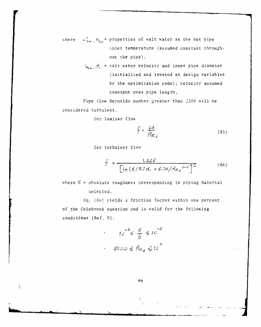
,,here & Q, properties of walt water at the hot pipe
inlet temperature (assumed constant through-
out the pipe).
= salt water velocity and inner pipe diameter
(initialized and treated as design variables
by the optimization code); velocity assumed
constant over pipe length.
Pipe flow Reynolds number greater than 2300 will be
considered turbulent.
for laminar flow
(,4 (S5)
for turbulent flow
."2 (86)i ( .z , .- 74/,<. "
where 6 absolute roughness corresponding to piping material
selected.
Eq. (86) yields a friction factor within one percent
of the Colebrook equation and is valid for the following
conditions [Ref. 9).
66
AIL,_

Considering the resistance coefficient for pipe minor
losses
Assume the inlet duct is the same size as thepipe inner diameter, but it is screened
k'= 1. (S-)
Assume piping enters evaporator through anarea which is abruptly changed [Ref. 11]
2
K ()]
where i~o = evaporator tube sheet diameter (assume tube
sheet diameter is twice as large as the inner
pipe diameter).
Summing the results of Eqs. (84), (S-1, and SS8 to
determine the total resistance coefficient, the pressure
losses due to piping can then be determined using Eq. '83).
If a variety of valves or fittings are to be included
with Eq. (84), Ref. 11 provides a representative listing of
equivalent length-to-pipe-diameter values.
To analyze the pressure drop across the evaporator
tubeside, we again use the Darcy-Weisbach correlation, but
for different design assumptions.
Assume inlets to evaporator tubing are wellrounded [Ref. 11]
67

Assume outlets of evaporator tubing expandto an infinite reservoir (Ref. 10]
SlIC (90)
Using the Reynolds number in the previous chapter,
Eq. (5), the corresponding friction factor Eq. (85) or (86),
and resistance coefficient can be determined
f L~ (91)
where Le,dL = evaporator tube length and inner tube
diameter and are initialized and treated as
design variables by the optimization code.
Summing the results of the resistance coefficient
in Eqs. (89), (90) and (91), the pressure losses due to the
evaporator design may be determined using the Darcy-Weisbach
correlation Eq. (83).
The results of the piping losses and core design
losses are equivalent to the hot pipe salt water pumping
system requirements
r" t p;' 6mVt- D~jSIcjN (92)
converting to pumping head
H, p ./ t (93)
68

Pumping power in terms of horsepower can be determined
using the following expression
- rH(~ (94)tip
where -' pump mechanical efficiency (designer input).
,r1,,=s salt water mass flow rate determined in
previous chapter, Eq. (2).
To equate parasitic pump losses to power input,
Eq. (94) is converted to the motor load requirement in terms
of megawatts electrical.
PHP( j)7PfP< C 1(95)
where - pump motor efficiency (designer input).
Because of the high salt water flow rates and rela-
tively low pumping heads, good engineering design would
dictate the use of axial flow (propeller) type pumps.
Using the algorithm developed by TRW [Ref. 9] from
data provided by Johnston Pump Co., and Process Equipment
Co. (distributors of Ingersoll Rank and Johnston Pumps),
the cost of salt water pumps can be expressed as
L )1 C.1 j X (96)
69

where
, '4
where dc, Vsw = inner hot pipe diameter, salt water velocity
(initialized for analysis and treated as
design variables by the optimization code).
The above algorithm is valid for the following con-
ditions
vertical, wet pit, propeller type pumps withcast iron steel columns with protective epoxycoating, stainless steel shaft and bronzeimpeller.
• pump size from 155,000 through 750,000 GPM
with total dynamic heads of 8 through 12 feet.
Eq. (96) has been adjusted for current pricing at a 10%
annual rate of inflation.
2. Cold Pipe Salt Water Pump.,,
Using Reynolds number
Z V Vs.
where properties of salt water at the cold pipe
inlet temperature (assumed constant through-
out the pipe).
= salt water velocity and inner pipe diameter
(initialized and treated as design variable
by the optimization code), velocity assumed
constant over pipe length.
70

Pipe flow characteristics and friction factor can be identi-
fied. A pumping analysis will be developed for the cold
pipe pump using the Darcy-Weisbach correlation, similar to
the development in the preceding section.
Considering the resistance coefficient for minor pipe
losses
Assume the inlet duct is well rounded [Ref. I1].
K= 0,6, (97)iN(.a-
Assume piping enters condenser through anarea which is abruptly changed [Ref. 10].
where T50 condenser tube sheet diameter (assume tube sheet
diameter is twice as large as the inner pipe
diameter).
Assume one ninety-degree elbow is required
in system [Ref. 11].
L5 0D
Summing the results of Eqs. (84), (97), and (98),
the total resistance coefficient can be expressed as
P L6#L)JtUk ' (99)
71
S---

where Lp = length of cold pipe.
c. = inner diameter of cold pipe.
Pressure losses due to piping can then be determined
using the Darcy-Weisbach, Eq. (83).
In analyzing the pressure drop across the condenser
tubeside, the Darcy-Weisbach correlation is used again, but
for different design assumptions.
. Assume inlets to evaporator tubing are wellrounded.
k C .5' (100)
* Assume outlet of condenser tubing expands toan infinite reservoir.
~ (101)
Defining Reynolds number for condenser tubeside
flow, while assuming
where / properties evaluated at condenser tubeside
bulk temperature (initially assumed equal to
cold pipe inlet temperature).
72
I I

average salt water velocity through
tubing, inner condenser tube diameter (both
are initialized and treated as design
variables by the optimization code).
The corresponding friction factor, Eq. (85) or (86), and
resistance coefficient can be determined
t (103)
where Lt,d , the condenser tube length and inner tube diameter
are initialized and treated as design variables by the optimi-
zation code.
Summing the results of the resistance coefficient
in Eqs. (100), (101), and (103), the pressure losses due to
the condenser design may be determined using the Darcy-Weisbach
correlation, Eq. (83).
A complete analysis of cold pipe losses must also
include the effect of density head and a corresponding increase
in pumping power requirements.
For most engineering problems involving the flow of
liquids through a pipe, where the temperature change in the
pipe is small, the density of the fluid is considered to be
a constant and the fluid is termed "incompressible." However,
the flow problem in OTEC cold pipe systems is unique. We can
continue to assume that there is negligible change in the fluid
temperature, virtually unaffected by the ocean thermal
gradients, because of the system's characteristic high mass
73

flow rates. However, the height of the water column (1500
to 3000 feet) inside the pipe requires the effect of fluid
compressibility to be taken into consideration.
The effect of an increase in density with depth
can be expressed by the integral
'-I
with a density head defined as2
e
Integrating the pressure-density variation, the
density head reduces to [Ref. 12]
H,, zz- F " Li (?e R)L K rM P4
where i( -- mean compressibility of wait water, f(salinity,
temperature and pressure).
reference density at which Km is evaluated.
Considering pressure at any depth obtained from the
integral,
-. e
the density head can be rewritten as follows
2Note that Z is measured as positive upward so that oceandepth values(ZL,,) are negative and (!Z- L)is a positivequantity.
74

Rigorous procedures for calculating the density
profile which is a function of temperature, salinity and
pressure may be found in Ref. 13; however, they will not
be discussed in this document.
For the purposes of simplification, the following
solution technique was developed:
(1) If the liquid in the pipe is taken to have a
constant density with respect to pressure, the compressibility
approaches zero; the density head can then be expressed as
(2) Converting the geometric term for elevation to
an equivalent integral expression
Zee
The reference density is taken to be the inlet value so that
and the density head can be rewritten as follows
(3) Assuming a linear distribution of density with
depth, due to temperature variations, as illustrated below
75

- L-
the following linear expression for density with respect to
depth may be formulated, where Z=O for convenience.
(4) Applying the equation developed in section 3 to
the density head integral above and integrating over the
range of values for sea water depth (z), the following
equation is derived as a linear approximation to the density
variation of sea water with respect to depth
/9
where ,e - curve fit evaluations of density for
specified depths of sea water. Data
extracted from Ref. 14.
The results of the piping losses, core design losses,
and density head are equivalent to the cold pipe salt water
pumping system requirements
76
- *H

Using Eq. (93), Eq. (105) can be converted to a
pumping head. Similarly, pumping power in terms of horse-
power can be determined using Eq. (44).
where
IIITr J,_ (106)
and /O5W = density of salt water evaluated for a
constant inlet temperature.
Vs.k 4;, = cold pipe salt water velocity, and inner
diameter (initialized and treated as design
variables by the optimization code). Note
salt water velocity through cold pipe is
considered to be constant.
Pumping power can then be expressed in terms of
megawatts electrical
P FCP X ~j~A FACTO' (107)
where 7_= pump motor efficiency (designer input).
Using the same arguments for the selection of an
axial flow (impeller type) pump, as used for the hot pipe
salt water pump, the pump cost algorithm developed by TRW
can be applied to the cold pipe salt water pump assuming
77
. . .. .. ... ., " - - !l l I~i am''
a . ......... . " ...

the required conditions are validated.
3f/,,= locc)c. r5 r. !].21,< (1 081
Equation (108) has been adjusted for current pricing at a
10% annual rate of inflation.
3. Ammonia Circulation Pump. ReC
The function of the ammonia circulation pump is to
circulate and lift saturated liquid ammonia from the condenser
hot well at state point 1 and increase its pressure to exceed
the operating conditions in the evaporator at state point 2.
In order to evaluate these characteristics, the
following pumping elements will be included in the analysis:
Piping losses (friction and minor).
Heat exchanger shellside pressure drop.
Thermodynamic pressure head.
Elevation head.
As in the preceding analysis, Reynolds number is used
Fto determine pipe flow characteristics
IV /
where 1 11 = saturated liquid properties of ammonia for
the temperature at state point 1 (assume any
temperature increase from pump work is negligible).
= inner pipe diameter (initialized and treated as
a design variable by the optimization code).
78

" =ammonia flow velocity determined from the pre-
ceding chapter, Eq. (50).
The ammonia pipe friction factor can then be deter-
mined from Eqs. (35) or (86), and the piping friction
resistance coefficient can be expressed as
L (109)
where L = ammonia circulation pipe length (designer input).
Considering the resistance coefficient for minor pipe
losses, assume there are four ninety-degree elbows in the
system
K= 4 L (110)
where - = equivalent length in pipe diameters for a standardp
elbow [Ref. 111.
Summing the results of Eqs. (109) and (110), piping
losses (friction and minor) can be determined using the Darcy-
Weisbach equation (93).
= F,,L,4 V (111)
The heat exchanger shellside pressure drop is also
included in the pumping head requirement because it serves as
a resistance to flow.
/9

Pressure drop across the evaporator shellside was
determined using the two-phase flow model (homogeneous)
expressed by Eq. (33)
AF~P AFRICriON 0 A1 C 4l r_ 'f.j LEVA7FICN (112)
Since the pump is required to lift the working fluid
to a higher elevation and increase its operating pressure,
the following elements must be included in the analysis:
Thermodynamic head
where z F, (113)
represents the difference in thermodynamic
operating pressure between state point 2 and
state point 1.
Elevation head
where Z - (114)
= datum.
. =elevation of the evaporator inlet above
datum (taken to be equal to evaporator
tube sheet diameter plus 25).
represents the lift head required to move the
working fluid to a higher elevation.
80

The results of piping losses (111), evaporator
pressure drop (112), the thermodynamic head (113) and
elevation head (114) are equivalent to the ammonia circulation
pump system requireements.
A ?p~r~ = ~ ~Th~frI ~AL~V4Tj\J(115)
Using Eq. (93) with ammonia properties, Eq. (115)
can be converted to pumping head and finally expressed as
pumping power (horsepower).
I'___ J )(116)
where / =1a = mass flow rate of ammonia determined by
Eq. (20) of the previous chapter.
" tj = pump mechanical efficiency (designer input).
Pumping power can then be expressed in terms of mega-
watts electrical
ffRCc)%: jS CON I~CNip-cc 1
where "'t= pump motor efficiency (designer input).
Because of high pumping head and moderate flow rates,
good engineering design would dictate the use of a single
suction centrifugal flow type pump.
81

Using the algorithm developed by Westinghouse Electric
Co. [Ref. 15] from data provided by Bingham Pump Division,
Portland, Oregon, the cost of the ammonia circulation pump
can be expressed as
=(kI +) 1.21 x , (118)
where M t = mass flow rate of ammonia r)
= specific volume of saturated liquid ammonia
at state point 1 (k'/fb,, J
Eq. (118) has been adjusted for current pricing at a 10',
annual rate of inflation.
4. Ammonia Re-flux PumpPME-_Lux
The function of the re-flux pump is to recycle
ammonia droplets which are not evaporated in the heat absorp-
tion process. Saturated liquid at approximately the heat
exchanger's operating pressure is lifted from the evaporator
d-ain to the ammonia feed inlet, for redistribution as droplets
across the evaporator tube bundle. (Drainage mass flow rate
is assumed to be equal to 30% of the evaporator inlet feed
mass flow rate.)
In order to evaluate these characteristics, the
following pump elements will be analyzed:
Piping losses (friction and minor).
82

Thermodynamic pressure head.
Elevation head.
As in the preceding analysis, Reynolds number is used
to determine pipe flow characteristics
where /-',V = saturated liquid properties of ammonia for the
average pressure across the evaporator.
/i = inner pipe diameter (initialized and treated
as a design variable by the optimization code).
V = ammonia flow velocity determined from the
evaporator drainage mass flow rate assumed
equal to 300 of the evaporator inlet feed mass
flow rate (assume velocity constant throughout
the pipe).
The re-flux pipe friction factor can be determined
from Eqs. (85) or (86), and the piping resistance coefficient
can be expressed as
(119)
where L ammonia re-flux pipe length (designer input).
Once again, considering the resistance coefficient
for minor pipe losses assume there are four ninety-degree
elbows in the system
83

4 -L (120)
where . equivalent length in pipe diameters from a standardD
elbow.
Summing the results of Eqs. (119) and (120), piping
losses (friction and minor) can be determined using the
Darcy-Weisbach, equation (83)
P = A-)[ (121)
In order to determine the thermodynamic pressure
head, the pressure drop across the evaporator for the
saturated ammonia liquid must be analy:ed. Since the
saturated vapor and liquid are in thermodynamic equilibrium,
the results of Eq. (11Z) apply. Therefore
AP P3 - Pa
Therefore, the thermodynamic pressure head is equal
to the pressure drop across the evaporator for the saturated
ammonia liquid.
6 (122)
Finally, the elevation head is equal to the elevation
of the evaporator feed inlet with respect to datum, the
drain outlet.
34

Therefore,
A ,F (123)
where ZI = datum, drain outlet.
Z2 = elevation of the evaporator inlet above datum
(taken to be equal to the evaporator tube
sheet diameter plus 10).
The results of piping losses (121), the thermodynamic
pressure head (122), and elevation head (123) are equivalent
to the ammonia re-flux pump system requirements.
AP =j /3? +-AP -. (124)
As before, using Eq. (93), Eq. (124) can be converted
to a pump head and finally expressed in terms of pumping
power (horsepower).
F/ IR~-LLJ~ ..~~j H(125)
where rf, = drainage mass flow rate.
= pump mechanical efficiency (designer input).
Pumping power can be expressed in terms of megawatts
electrical
, -FL~Ux(l = -u__X LONv ERSlCAi FACT CR (126)
85
-

where T' pump motor efficiency (designer input).
Using the same arguments for the selection of a
centrifugal pump, the pump cost algorithm developed by
Westinghouse can also be applied to the ammonia re-flux
pump.
0 b4 Sx,. 'o'/oo / f, 1 X 1 1 7
where r1] mass flow rate of evaporator drainage ammonia
V4 = specific volume evaluated at the average
evaporator pressure (ft/ib,)
Eq. (127) has been adjusted for current pricing at
a 10% annual rate of inflation.
5. Parasitic Pump Losses
Parasitic pump losses is the summation of electrical
auxiliary pumping requirements (hotel and maintenance loads
not included) determined by Eqs. (95), (107), and (126).
LOs PHP P P ' PC .C PRE-FLUX (128)
86

V. TURBINE AND ELECTRICAL POWER
A. INTRODUCTION
The turbine generator is one of the critical elements
of the OTEC power system. Its energy conversion efficiency
and efficiency of design have a major effect on the overall
system performance. To illustrate this point, Ref. 16
reported that a three-point change in turbine efficiency from
85 to 88% results in a 3.6% increase in gross power, and a 5%
increase in net power developed.
This chapter will describe the analysis to evaluate the
expansion turbine thermodynamic properties and generator
output. The use of these properties will determine the
internal turbine efficiency and outlet quality subject to
design and thermodynamic constraints. The relationship
between the condenser operating pressure (design variable)
and the turbine outlet quality will be used to initialize
the heat rejection characteristics of the condenser.
General literature on turbomachinery designed for OTEC
closed cycle systems indicates that a turbine having the
following characteristics
Double flow, axial inflow,
Four stages of expansion,
Operating at 1800 RPM,
provides the optimum aerodynamic design (Ref. 16]. However,
it is not the intent of this thesis to analyze the geometry
8 7

and performance parameters of the turbine. Turbine geometry
such as
Specific speed and specific diameter,
Wheel diameter,
Rotational speed,
Blade height,
Blade stresses,
should be treated as a separate systems problem using
optimization to improve state-of-the-art design.
Parasitic losses due to the following generator turbine
inefficiencies will be evaluated in this section.
Generator mechanical and electrical.
Turbine mechanical.
As an overview of the turbine-generator analysis, the
following major steps of the algorithm are listed in order
of their execution:
Gross electrical output with no parasitic losses(129).
Enthalpy at state point 5 (130).
Turbine outlet quality (131).
Entropy at state point from a specified outletquality (132).
Quality and enthalpy at state point 5s (133, 134).
Internal (adiabatic) turbine efficiency (135).
Turbine cost analysis (137).
Generator cost analysis (138).
In the following section, the basic steps summarized above
will be described in detail.
88

B. ANALYSIS OF THE TURBINE AND ELECTRICAL POWER REQUIREMENTS
1. Gross Electrical Output and Inefficiency Losses
If the net electrical output required is indicated
by (in terms of megawatts), the gross electrical load at
the turbine shaft can be expressed as
= + KOss (129)
Th-AI )L4AJ
where PLOS = parasitic pump losses determined by Eq. (128).
11TM = turbine mechanical efficiency (designer
input).
= generator mechanical and electrical
efficiency (designer input).
The loss of electrical output due to generator-
turbine inefficiencies is equal to
2. Turbine Efficiency
The power developed across the turbine is
where r = mass flow rate of ammonia given by Eq. (48).
h4= enthalpy at state point 4, Eq. (42).
From this, the enthalpy at state point 5 can be calculated.
If we initialize the operating pressure of the con-
denser in terms of PS, the following relations may be expressed
89

IiP6 (130)
Therefore, it follows that the turbine outlet quality,
XS, can be determined from
Ii +i x~(s-1 (131)
Having established the moisture separator outlet
pressure and temperature, Eqs. (40) and (41), the entropy
at state point 4 can be determined for a known separator
outlet quality (designer input) using the following
relations
S~ ~ ~ -4 -)141 1-454 - S4-f - X ( 54j- S4-) (132)
For isentropic turbine work,
54- S53 (133)
the quality at state point 5s may be determined using the
following relations
+ -' (134)
Having determined the quality at state point 5s, the
enthalpy can now be determined.
90

h~s -4-xs ~~--K (135)
Using the results of Eqs. (41), (130), and (132),
the internal turbine efficiency (adiabatic) can be deter-
mined, expressed by
r (136)
To ensure a realistic selection of internal efficiency,
the following constraints are attached to the optimization
code
* X5 <N
3. Turbine Cost Analysis
The ammonia turbine cost is based on an algorithm
developed by Westinghouse to estimate manufacturing costs
[Ref. 15].
24 2 0 6,,37 /f3/N F (137)
where = gross electrical output in KW.
A4 : 2 (for a double flow turbine).
= flow price factor (1.0 for single-flow, 1.447
for double-flow).
91

The above algorithm is valid for the folowing
conditions:
Double flow, axial inflow.
Multi-stage.
Operating at 1800 RPM.
The generator cost will be based on an algorithm
developed by TRW from data provided by selected manufacturers,
Al .C2 3 b14-J- *C.-J1.I x 1 (138)
and is valid for the following conditions
1800 RPM rotor speed.
• power factor 0.8.
Eqs. (137) and (138) have been adjusted for
current pricing at a 10% annual rate of inflation.
92

Vr. CONDENSER
A. I'TRODUCTION
As indicated in the introduction to Chapter III, several
heat exchanger concepts have been proposed for the closed-
cycle OTEC system, with variations in their design.
The analysis to be presented for the condensing heat
exchanger will be based upon the following design
characteristics:
Single-pass shell and tube heat exchanger.
Horizontal/vertical orientation of tubes with anequilateral triangle or square tube profile.
Smooth plain-tube configuration (no enhancements).
Tube material (titanium or aluminum based on a30-year life-cycle criterion).
Biofouling control based upon an achievable
fouling factor.
Heat exchanger centerline located on sea surface.
As an overview of the condenser analysis, the following
major steps in the algorithm are listed in order of their
execution:
Initialization of design variables (DV).
Tube length.
SW velocity through condenser tubes.
Outer tube diameter.
Tube profile pitch ratio.
Amount of heat rejection (139).
Tubeside bulk temperature (142).
93

Total number of tubes (143).
Log mean temperature difference (144).
Conductance (146).
Number of transfer units (145).
Heat exchanger effectiveness (147).
Initially assume a value for ammonia heattransfer coefficient (151).
Single tube conductance (148).
Average heat rejection per tube (152).
Film temperature (153).
Revised ammonia heat transfer coefficient (154, etc.);iterate with (151).
Tube profile, flow parameters across the tubebank (158, etc.j.
Tube sheet diameter (163).
Condenser shellside pressure drop for two-phaseflow (166).
Revised properties at state point 1 (171, 172);iterate with (21).
Overall heat transfer coefficient (173).
Total heat transfer surface area (174).
Revised condenser tube length (175).
Heat exchanger cost analysis.
In the following section, the basic steps summarized
above will be described in detail.
B. ANALYSIS OF THE CONDENSER
1. Amount of Heat Rejection,Q
Using the calculated value for enthalpy at state
point 5, equation (131) from the previous chapter, the ideal
94

values at state point 1, Eq. (211), and the steady-state mass
flow rate of ammonia, Eq. (S), the amount of heat rejected
by the condenser can be expressed as
N ~ (139)
2. Tubeside Bulk Temperature
As in condenser tubeside Reynolds number, salt
water properties will be evaluated at bulk temperature,
initially assumed equal to the cold pipe inlet temperature.
Using this premise, the -ondenser salt water capacity
rate can be evaluated
(140)
where Up. = specific heat of salt water initially evaluated
at the cold pipe inlet temperature.
, mass flow rate of salt water through the cold
pipe previously evaluated by Eq. (10").
Using the results of iqs. I.39) and (40), and the
known cold pipe inlet temperature, the condenser salt water
outlet temperature may be evaluated from the basic expression
where ] : = condenser salt water outlet and inlet
temperatures, respectively.
Having determined the condenser salt water outlet
temperature. the revised bulk temperature zan be expressed as
95

AA9B567 NAVAL POSTGRADUATE SCHOOL MONTEREY CA F/G 20/13! OPTIMIZATION OF A LOW DELTA T RANKINE POWER SYSTEM. (U)
DEC 80 R C SCHAUnEL
UNCLASSIFIED MmmmmmEmmmmnmmmuhfnnuunhEmnEEEmhmmEmmhEEEmhEmhmhEEmhIEmmmnEmmmnmhEEIEmmhEEmhmnnmnhE

II 11.01.IIIII
111111.8
1111 25 I2511 11.6
MICROCOPY RESOLUlJION HTI T CHARI
N I'll

2
Using the revised condenser bulk temperature and
iterating with Eq. (102) corrects the operating temperature
for salt water properties which are essential to the
analysis.
3. Total Number of Condenser TubesIJt
Since the mass flow rate of salt water through the
cold pipe is equivalent to the mass flow rate through the
condenser, according to the law of continuity,
it follows that the number of condenser tubes for a specified
tube diameter, can be evaluated using the following expression:
4
where = average salt water density evaluated at
bulk temperature.
= inner tube diameter (initialized and treated
as a design variable by the optimization code).
V = average salt water velocity through the con-
denser (initialized and treated as a design
variable by the optimization code).
96

4. Log Mean Temperature Difference,LMTD
Using the result of Eq. (141), the known pipe salt
water inlet temperature, and the inlet temperature of
ammonia evaluated at state point 5, the LMTI) of the condenser
may be expressed as
LMTD 7c. (144)
S. NTU-Effectiveness Relations
The number of transfer units which is a measure of
the condenser size can be determined from the basic
expression
NTU UoA. (14S)
where the conductance (UA.)of the heat exchanger is a
function of the heat absorbed and the LMTD.
c = ( LIA.)L D (146)
The condenser effectiveness can then be expressed as
N- r u )( 1 7
for a two-phase flow, regardless of the flow geometry.
97

6. Single-Tube Conductance, U.A.
Using the resistance analysis derived in Chapter III,
Section 4 for an initialized tube length
L=LL
the heat exchanger conductance for a single tube can be
expressed as
-.dL . L A . (148)
where w = tubeside heat transfer coefficient.
Rfs = salt water fouling heat transfer resistance.
= thermal conductivity of the tube material.
AoAi= total outer and inner tube surface areas
(including fin and bare tube); tube length
is initialized and treated as a design
variable by the optimization code).
= ammonia fouling heat transfer resistance
i, f=
1 *outer and inner total fin efficiency
a. Tubeside Reynolds Number
Since the salt water heat transfer correlation
is dependent on tubeside flow, Reynolds number must be
evaluated P? . o .u VW s,14S
where /O42,- salt water density and viscosity are
evaluated for the fluid's bulk temperature.
98

, inner diameter and average salt water tube
velocity.
Reynolds numbers greater than 2300 will be
indicative of turbulent flow [Ref. 31.
b. Salt Water Heat Transfer Coefficient, h,Once again the empirical relationship proposed
by Sieder and Tate [Ref. 3] will be used for laminar heat
transfer in tubes and as defined by
1/3 113 0.14
Nusselt and Prandtl numbers are defined as
= h w di (149)
cp., 115 (150)
where dynamic viscosity, specific heat, and thermal conduc-
tivity of salt water are evaluated at the salt water bulk
temperature.
The effect of the viscosity ratio in the
Sieder-Tate equation is considered negligible, and will
hereafter be dropped from the expression. The assumptions
and validity condition associated with the Sieder-Tate
equation were stated in Chapter III, Section 4, and will not
be repeated here.
99
. . . ,

For fully developed turbulent flow, again the
Dittus=Boelter correlation [Ref. 3] was used.= 0.8 0.3
c.C23RI
Nusselt and Prandtl numbers are previously
defined by Eqs. (149) and (150). Assumptions and conditions
for validity were stated in Chapter III, Section 4.
c. Salt Water Fouling Heat Transfer Resistance
As indicated previously, it will be
assumed that the foulding resistance for tubeside salt
water can be maintained at .00025(hr.tfF/ATU)
d. Ammonia Shellside Heat Transfer Coefficient,AN 3
Initially, kJ,, will be assumed
h41-- 10oo (BTU/h,.+F) (151)
since its value cannot be directly calculated during this
phase of the analysis.
Using the following single-tube thermal
resistance I
Z= I
7p3 I Ftoid;
Z iTKL
- o,,, d. L
100
;~1'~

an initial value for single tube conductance (outer tube
surface) may be calculated
L.A.= 1
7. Film Temperature for Property Evaluation, Tr
In order to evaluate the shellside ammonia heat
transfer coefficient, working fluid properties must be
evaluated at the film temperature.
This can be accomplished by using the results of the
single tube conductance, the tube side bulk temperature and
the working fluid saturation temperature, expressed in the
following equation for single tube heat transfer rate (average).
( UCA (TS-T8ULK) I)
Again using the resistance analysis as in Chapter III,
the shallside wall temperature may be expressed as
Twz~ = Tax (RI -f- z I+?3)
Knowing the shellside wall temperature and the free-
stream temperature, the film temperature can be derived from
their arithmetic mean
T1VV- Ts- (153)
For purposes of this calculation, saturated tempera-
ture conditions at state point 5 are taken to represent
101

free-stream conditions, when in fact the two-phase process
will experience a pressure drop and a corresponding drop in
temperature.
8. Revised Shellside Ammonia Heat Transfer Coefficient,
This analysis will include correlations for both
horizontal and vertical heat exchangers.
In the horizontal-tubed condenser, Nusselt's
correlation was used as a predictor [Refs. 7 and 17],
for laminar flow
= q(Kf L) (154)
where W - estimate of ammonia mass flow rate across
each tube.
= properties evaluated at film temperature.
L = tube length (initialized and treated as
a design variable by the optimization code).
This correlation is probably conservative, since it
does not consider turbulence due to high vapor velocity
or splashing of condensate [Ref. 7].
For turbulent flow, Nusselt's correlation is increased
by 10% as recommended by Jakob [Ref. 17]
04 L/1 (155)
102
4.j

The laminar-turbulent transition point is defined by
a Reynolds number of 2100, where the pseudo-Reynolds number
for.film-type condensation on horizontal tubes is defined
as [Ref. 7]
where r = mass flow rate of condensate per tube over its
length.
In the vertical tubed condenser, both Nusselt's and
Kirkbride's correlations were used as predictors [Ref. 7].
For laminar flow, Nusselt's correlation is increased
by a factor of 1.28 as recommended by McAdams [Ref. 7]:
P71.~ 747( 4 'jz) () (156)
where r= mass flow rate of condensate per tube over itsdiameter.
For turbulent flow, Kirkbride's correlation is applied
-Z / 0.4
\ 0,.0077 (1S7)
The laminar-turbulent transition point is defined by
a Reynolds number of 1800, where the pseudo-Reynolds number
for film-type condensation on vertical tubes is defined as
[Ref. 7]
103
v '

After using the pseudo-Reynolds number to establish
the flow in which regime the system is operating, the revised
heat transfer coefficient for film-type condensation may be
calculated and then iterated with the initial assumption
for the shellside heat transfer coefficient, Eq. (151).
Once again this will have a convergence effect on variables
in which the shellside heat transfer coefficient is a
function, moving closer to actual OTEC system operating
point characteristics.
9. Tube Profile, Flow across Tube Bank, and TubeSheet Diameter
Since the condenser tube bundle involves multiple
rows of tubes, the geometry of the tube profile arrangement
is important to determine the shellside heat transfer coeffi-
cient, the tube sheet diameter and the shellside pressure
drop associated with the "homogenous" two-phase flow model
[Ref. 4].
Using the same arrangements shown in Chapter III,
Section 2, S
IN-LINE Sn
~,= P~ ~(158)
A=: 5n (159)
104
1IV- b

where Sri = pitch ratio x outer tube diameter.
t = pitch ratio (initialized and treated as a
design variable for the optimization code).
Ap = tube profile area per tube
STAGGERED 30.S FLOW
where
!n -2 Pe, do sim 3c" (160)
5P PR d, cos53c (161)
Ap = Sp(162)
the ratio of minimum flow area to the frontal area can be
expressed as
-- (163)
Using the selected tube profile geometry and know-
ing the number of condenser tubes by Eq. (143), the tube sheet
diameter for the condenser design can be evaluated from the
following expression
i
105 _

NtJA 7 JTFSO2 (164)4
where Tp = Tube sheet diameter.
To analyze the shellside ammonia flow velocity, the
following control volume is introduced (turbine generator
discharge and top portion of the condenser).
I YI'".
Mf
Since the mass flow rate remains unchanged across
any boundary
Furthermore, if we assume the condenser has the
capability to evenly distribute vapor across the tube bundle
(distribution baffles), the following development applies
to the vapor coverage:
Let (Af)V AP
where ?P1 = percent of tube frontal area which is covered
by vapor.
106

where As = condenser inlet cross-sectional area.
V7 = turbine discharge ammonia velocity.
Therefore .vs.
If it follows that the turbine discharge
velocity is equal to the average velocity of ammonia at the
tube frontal area boundary. A determination of the distri-p
bution fraction requires a detailed knowledge of the
design of the turbine/condenser interface. In the absence
of this information it is assumed that
v+ = \15
A similar argument could be presented for a vertical
tubed condenser where turbine discharge is admitted to a
distribution ring that bands the condenser tube bank.
Exhaust vapor would travel radially through the tube bundle
and then collect at the bottom after vertical film-
condensation. I . . .
I Is
Vside S
I I
',-- I
L[__Again, in the absence of a detailed design, it is assumed
thatV',E= vs-
107

Considering the minimum free-flow area for a horizontal
tubed condenser, A~f can be derived using Eq. (163) and the
projected frontal area.
A '~i Lt
Aff= ( Sdr )s. (16S)
where Af = the flow frontal area.
Lt = tube length.
For vertical condensers
A; = 1.s- FROAITAL LGN'6rH OF VAPOR? IkLEF FLOW,
Using the previously calculated value of the ammonia
flow rate and Eq. (165), mass velocity for the minimum free
flow area can be expressed as
Al'1 (166)
10. Pressure Drop of Two-Phase Flow across a Bank of
lubes,/AP
The pressure drop in the two-phase flow condensing
heat exchanger will be determined using the homogeneous
model introduced in Chapter III. The model will consist of
three components -- friction loss, momentum change, and
elevation pressure drop arising from the effects of gravity.
The local pressure drop for a two-phase flow may be
expressed as
108
LM -

C&4 ~ j~iF/CJ ij\JTJH ~ j~A~lI'J(167)
For a given channel length, Lc , the pressure drop
components can be expressed by
F FITO L,: (168)
,1 E&1 rum . (169)
7. Lc (170)
where = single phase friction factor by Jakob expressed
in Eq. (35) or (36).
= mass flow velocity determined from Eq. (166).
LC= channel flow length, defined for horizontal
tubed condensers as LC=TsD (tube sheet
diameter) and for vertical tubed condensers
as Lc=Lt (tube length).
D. = equivalent diameter of flow channel, defined by
- mean specific volume defined by
109

where X = quality of mixture (state point 5).
4 = specific volume of liquid (state point 1)
if = specific volume of vapor (state point 5).
All components of the pressure drop model Eqs. (168, 169,
and 170) can be determined using the preceding information.
11. Revised Properties at State Point 1
Since Eq. (167) represents the pressure drop across
the condenser shellside, the actual pressure at state point 1
or condenser outlet may be determined from
'PI (NeVV) = I - A6 C 0 i (171)
where P, is previously described as the condenser operating
pressure for the ideal cycle.
Operating on the saturated liquid line on the
Temperature-Entropy diagram, the following properties
are defined:
hi EVV hf~pNw Pa~ sr(P (172)
The subscript tNew) representing a revised property
will hereafter be dropped from the expression in Eq. (172).
Until now, we assumed the condenser outlet tempera-
ture and pressure were designed to operate as an ideal system,
without a pressure drop. Therefore, using the revised
temperature at state point 1 and iterating over the range
from Eq. (21) until an acceptable convergence criterion is
achieved, all the preceding variables as function of T,
110
'- 2t

will be reevaluated to complete the closed-loop cycle of the
simulated OTEC power system.
12. Overall Heat Transfer Coefficient, LL
The quantity "U" represents a measure of the total
thermal resistances in the flow path. Therefore, using the
tube conductance expressed in Eq. (148) which is divided by
the outer heat transfer surface area of a single tube, the
overall heat transfer coefficient for the condenser can be
determined.
The thermal resistances are now expressed as
hR,-4 .
R.3 =~I~ La
and the overall heat transfer coefficient for the condenser
may be calculated using
U0 Ri R z 4-R +Fs (173)
I,-- -. ,-

13. Total Condenser Heat Transfer Surface Area,At
Having determined the corrected number of condenser
transfer units (145), salt water capacity rate (140) and
overall heat transfer rate (173), the total condenser heat
transfer area can be calculated from the NTU expression
NTLJ= LJ0 t (174)
14. Revised Condenser Tube Length
Using the total heat transfer surface area calcu-
lated from Eq. (174) and the total number of condenser
tubes (143), the revised condenser tube length can be deter-
mined from the basic expression
A~ N+T J Lt(-v !ep~) (175)
At this time, it is necessary ot iterate the condenser
design until the two values (initial and revised) of the
tube length converge. This iteration may be accomplished by
the COPES routine if the following constraint is defined
Minimization of this difference will cause continual
adjustment of the required tube length, already treated as
a design variable by the optimization code.
112

15. Condenser Heat Exchanger Cost Analysis
As indicated in Chapter III, TRW developed sets of
equations to represent the costs of various heat exchanger
component parts for shall diameters ranging from 10-35 feet
and 35-50 feet [Ref. 9].
The following are the TRW component cost equations
for the condensing heat exchanger. Prior equation reference
numbers will be substituted where equalities exist with the
evaporative heat exchanger component cost expressions.
for tatbe sheet diameter 10-35 feet
Drilling time/tube sheet thickness. (58)
Thickness of the tube sheet. (59)
Tube sheet labor cost. (60)
Tube sheet material cost. (61)
Tube installation cost. (62)
Heat exchanger drill cost. (63)
Ammonia distribution plate and bafflescost.
-X 4 N, T 2,. (176)
• Bustle, flanges, channels and flowplate cost.
2#
=3C f i es"Z e TSO (177)
Tube material cost.
fr L () .C t)N d/1,6 (178)
113

where c1 curve fit of tube material cost
per foot.
= tube machining cost if required.
* Heat exchanger header cost. (67)
• Water inlet, nozzles and support cost.
Tube welding costs (Titanium tubes). (69)
The sum of the preceding costs would equal the cost
to fabricate one OTEC condenser with a tube sheet diameter
of 10-35 feet (all the preceding component costs have been
adjusted for current pricing at a 10% annual rate of
inflation).
If our analysis is based on a 30-year life-cycle
criterion, no adjustments are necessary to any component cost
equation if titanium tubing is selected. However, using
Al 5052-0, the expense of retubing must be considered to meet
the 30-year life-cycle criterion, as in the cast of the
evaporation. For convenience, and possible subsequent
modification, these considerations are repeated here.
Based upon the utility of Al 5052-0, two complete
condenser retubings will be required to meet the basic 30-year
criterion. This implies Eqs. (62) and (178) must be modified
to reflect the costs of retubing at the 10 and 20 year point
in the cycle.
114

Aluminum tube installation cost.
C~4- Lr )i IC (1-) ( (180)
where L = projected annual inflationary
rate (input by customer).
Aluminum tube material cost.
Cq rM~ CrJsit(tL L2 J(11
for tube sheet diameter 35-SO feet.
Drilling time/tube sheet thickness (58)
* Thickness of the tube sheet. (59)
* Tube sheet labor and material costs(titanium). (72, 73)
Tube sheet labor and material costs(aluminum). (74, 75)
Tube installation cost. C76)
Tube material cost. (178)
Heat exchanger shell cost. (77)
Ammonia distribution plate andbaffles cost.
r LpN+ O.qTJ (182)
Bustle, flanges, channels andflow plate.
;.1,f (183)
C FF= 32. e24 T50 Ve 13
Heat exchange head cost.'.43
CJE q3q. zYS (184)
i 15

• Water inlet, nozzles, and supporterscost.
Tube welding cost (titanium tubes). (82)
As indicated previously, the cost to fabricate one
OTEC condenser with a tube sheet diameter of 35 to 50 feet
is equal to the sum of component costs (note, all the
preceding component costs have been adjusted for current
pricing at a 10% annual inflation rate).
For an analysis based on a 30-year life-cycle
criterion, the additional costs for replacing aluminum
tubing must be considered and Eqs. (180) and (181) apply.
116

VII. NUMERICAL OPTIMIZATION
A. INTRODUCTION
Nearly all design processes attempt the minimization or
maximization of some parameter or design objective. For
the design to be acceptable, it must satisfy a set of con-
straints which impose limits or bounds on design parameters.
For the stated problem a computer program can be written
to perform the basic analysis of the proposed design. If
any parameters fall outside the prescribed bounds, the design
engineer changes the parameters and re-runs the program. In
effect, the computer code provides the analysis with the
engineering making the actual design decisions.
A logical extension to the computer-aided approach is a
fully automated design, where the computer also makes the
actual design decisions and performs trade-off studies. The
COPES program provides this automated design and trade-off
capability by the use of the optimization program COPES/CONMIN
[Ref. 18]. COPES is an acronym for Control Program for
Engineering Synthesis, and CONMIN is an acronym for CONstrained
function MINimization. Subsequently, a FORTRAN analysis
program simulating a closed-cycle OTEC power system can be
coupled to the COPES program for automated design, using
some basic programming guidelines [Ref. 18].
117

B. COPES/CONMIN
There are many numerical optimization schemes available
to the engineer. Methods employed by these schemes fall
into four basic categories: random search, sequential
unconstrained minimization, optimality criteria, and direct
constrained optimization. The optimization program,
selected for automated design analysis of the simulated
OTEC power system, is based upon direct constrained
optimization.
Before any discussion of the optimization technique,
basic definitions are summarized for convenient reference
[Ref. 19]:
* Design variables - those parameters which the
optimization program is per-
mitted to change in order to
improve the program.
Objective function - the parameter which is to be
minimized or maximized during
the optimization process.
Inequality constraint - one-sided conditions which
must be satisfied for an
acceptable design.
Equality constraint - condition which must be
equaled for the design to be
acceptable.
118
I *

Side constraints - upper and lower bounds in a
design variable.
Assuming that the FORTRAN analysis program has been
developed and a particular objective function has been
selected, the general optimization problem can be stated
as [Ref. 20]:
Find the vector of design variablesX, to
Minimize FC') (186)
Subject to the constraints:
i,,Nc,; (187)
H ±(0) j=I,NEQ (188)
VL B- 1XVUB L=iNOV (189)
where X = the vector containing the set of independent
design variables.
F(9) = the objective function to be minimized.
j(<) = inequality constraint (NCO4 is the number
of such constraints).
Hj(x) = equality constraint (NEQ is the number
of such constraints).
VL13/VUBL= lower and upper bounds, respectively,
on the design variables.
If all inequalities of Eqs. (187) and (189) are satisfied,
the design is said to be feasible if any constraint is not
satisfied, the design is infeasible. If the objective function
119

is a minimum and the design is feasible, it is said to be
the optimal design.
In order to start the optimization algorithm, the
initial set of design variables,X , must be specified. It
is desirable, but not essential, that the initial design
variables provide a feasible solution. The optimization
algorithm will then proceed in an iterative fashion using
the following relationship
where = the iteration number.
scalar quantity which defines the move in the
search direction.
vector search direction which will reduce
the objective function (useable direction)
without violating constraints (feasible
direction).
To solve this problem, the optimization program
COPES/CONMIN is used (Ref. 18]. CONMIN uses the Fletcher-
Reeves algorithm for locally unconstrained problems [Ref. 20]
and Zoutendijk's method of feasible directions (modified to
improve efficiency and reliability and to deal with designs
which do not initially satisfy all the constraints) for
locally constrained problems [Ref. 21].
However, CONMIN does not handle equality constraints
directly, but rather by means of penalty parameters. To
achieve this, the objective function is augmented as follows
120

[Ref. 19]
haq
(>.K (190)j= I
and the equality condition of Eq. (188) is treated as an in-
equality constraint
The penalty function approach effectively satisfies the
equality constraint while maintaining the rapid convergence
characteristics of the CONMIN program.
The numerical optimization problems of equations (186)
through (190) are very general, allowing for any number of
design variables and constraints. In assessing the value of
optimization, the automated design provides a very attractive
approach to numerical optimization; however, there are both
advantages and limitations to these techniques [Ref. 203.
Advantages:
Reduction in design time.
Systematic design procedure.
Applicable to a wide variety of design variablesand constraints.
Virtually always yields some design improvement.
Not biased by engineering experience.
Requires a minimal amount of man-machine interface.
Limitations:
Computer times may increase dramatically as thenumber of design variables increases. A practicallimit imposed by the current state of the art formost problems is 30 design variables.
121

Optimization techniques have no stored experienceto draw upon; the validity of the result islimited to the validity of the analysis program.
The results of the optimization are as correctas the analysis program is theoretically precise.
Optimization algorithms used here cannot deal withdiscontinuous functions.
* The optimization program will not always obtain aglobal design optimum and may require restartingfrom several different points to acquire reason-able assurance of obtaining the global optimum.
The analysis program must be properly structuredto couple with the COPES/CONMIN optimization code.
C. DESIGNATED DESIGN VARIABLES, CONSTRAINTS AND OBJECTIVE
FUNCTION
To assist in the interpretation of the enclosed OTEC
power system FORTRAN analysis, the following summary identi-
fies the design variables, constraint functions and objective
function used in the analysis and subsequently operated
upon by the COPES/CONMIN optimization code. These parameters
are all contained in a labeled COMMON block in the computer
code, referred to here as "GLOBAL COMON." Specific
GLOBAL COMMON location numbers and upper/lower bounds for
operating parameters summarized below can be located in
Appendix C.
Design Variables
Inner cold pipe diameter
Inner hot pipe diameter
Inner ammonia circ pipe diameter
Inner ammonia re-flux pipe diameter
122

* Evaporator operating pressure
* Condenser operating pressure
Outer condenser tube diameter
Outer evaporator tube diameter
Evaporator tube length
Condenser tube length
* Condenser tube salt water velocity
Cold pipe salt water velocity
Evaporator tube salt water velocity
Hot pipe salt water velocity
* Evaporator tube profile pitch ratio
Condenser tube profile pitch ratio
Constraint Functions
Operating system pressure ratio
Upper temperature bound of ammonia
Lower temperature bound of ammonia
Satisfactory enthalpy at state point 5
Satisfactory quality at state point 5
Satisfactory condenser tube length
Internal turbine efficiency
Evaporator tube sheet diameter
Condenser tube sheet diameter
Objective Function
Cost of major power system components
123
i17%,1 7

VIII. CONCLUSIONS AND RECOMMENDATIONS
A. CONCLUSIONS
1. The use of an analysis code for OTEC power systems
coupled to COPES/CONMIN optimization code provides a power-
ful tool to design an optimum power system for the desired
net electrical output, measured against the objective
function. Such a design could permit construction of higher
capacity systems using the optimized modules as substations
of the total power plant.
2. The analysis code coupled to COPES/CONMIN provides
an excellent vehicle to evaluate proposed designs relative to
a true optimum. Tables 1 through 4 illustrate the result of
preliminary calculations using the analysis code with an
objective function to minimize system cost. From these, the
following conclusions can be drawn concerning horizontally
oriented aluminum (Al-5052) and titanium-tubed heat exchanger
power systems:
a. The cost/KW output is nearly constant over the
range of optimum designs for both titanium and aluminum tube
heat exchangers.
b. During testing for feasible plant designs in
increments of S MW (net) electrical output, it was observed
that a higher megawatt output plant could be achieved with
titanium-tubed heat exchangers than for aluminum (Al-5052).
For titanium-tubed heat exchangers, a 25 MW (net) power
124
WIN771
system is a feasible design; however, aluminum-tubed systems
could not provide a feasible design for the same output.
Titanium tubed plants failed to produce a feasible design
for a 30 MW (net) output power system. In both cases of
infeasible design, the constraint which was consistently
violated was turbine internal efficiency, set at 90% for
current state-of-the-art design.
c. The energy conversion and efficiency of design
of a turbine-generator has a major effect on the overall
system performance as indicated in paragraph b above.
d. The cost/KW output for titanium-tubed heat
exchangers is one third the cost/KW output for aluminum-tubed
heat exchangers using a 30-year life-cycle criterion, with a
10% annual inflation rate and retubing at 10 and 20 year
marks with AL-50S2 tubing.
e. Aluminum-tubed heat exchangers have larger tube
bundle volumes, with volumetric differences between aluminum
and titanium varying from 26.1 to 11.8% for evaporators and
23.2 to 7.4% for condensers over the range of net power
levels considered. In both cases volumetric differences
diminish as the system's net electrical output increases to
20 megawatts.
f. COPES/CONMIN has provided optimum designs for
each incremental output power level. By manipulating the
specified design variables, subject to imposed constraints,
COPES/CONMIN has created designs whose geometry and operating
125

parameters cannot be scaled on the basis of net power output
(10 MW). Therefore, designs for component geometry at
increasing power levels based upon such simplistic scaling
criteria will not achieve an optimum design with respect to
the cost objective function.
B. RECOMMENDATIONS
1. Evaluate additional objective functions including:
a. Minimize heat exchanger volumes.
b. Minimize parasitic power losses.
c. Maximize thermodynamic efficiency.
d. Maximize net electrical output.
2. Perform a sensitivity analysis on power system design
variables to evaluate their influence on component and system
performance. This allows the designer to prioritize system
components which can provide improvement in the objective
function for a corresponding improvement in component design.
3. Considerahle uncertainties are associated with the
expressions used to estimate component performances (two-phase
pressure drops, film coefficients, etc.). The code should be
tested to determine the sensitivity of system design to these
uncertainties.
4. Expand the code to include the use of enhanced heat
transfer techniques and evaluate the influence of increased
piping friction factors on pumping power requirements.
126
wak"-l

5. Evaluate proposed OTEC designs using proposed system
parameter inputs, comparing both the basic analysis and the
optimization output.
6. Select other analytical expressions for heat transfer
coefficients to validate the performance and output of the
existing code.
7. Evaluate the effect of a smaller thermal difference
seen by the power system and its influence on a feasible
design for a specific net electrical output.
8. Evaluate the cost aspects of using variable-pitch
pumps versus fixed-blade for a variable thermal gradient
environment.
9. Evaluate and verify the influence of incremental
improvements (percent) in turbine internal/adiabatic efficiency
with respect to gross and net electrical outputs and compare
with the results reported in Ref. 16.
127

= ;L rn - U,- - 0 l Vn (D
tfl LLn Vc %D tn LM L" (N(N U
$4 q ~ V0 Ln U, LA0 0
x
;", J4 ;4 - Oa) r" Ln 0n rU- U, tn
(N -I U, - V) V-0 0-~~ ) N-
N--
0N 00 \ N ,
** t') r-4 N- *1 ElNl-
0
m <
o- U, N- U, -1V
-t " (N N C; 14 N7 C -OI
r= (N ( 0 ~ 0 0 e tn -4 LnN
0N Z C4N D D " -T
- Z -4
E.-. E- (
<4 E- wO 0
E- > E- -
E- z/ E0 E- E -N - -
128

t A 0 0 LAO ' 0
r - t n - 0 1
LA t' 00 LA * L LO L
00 LAtn 0 0- L
:9 o r - LA \ LA
- ~\ 00 On~* \ L C )C- C- * - O
LA C ~ - 0 0 ~ -4 ~t- t'~ * CO A7!
-SL SL SL C,~'. *
-n tdI r- r4~t I A N L
0
0. ton LA LA r- 00
S cq C LA LA 00 01*0ON C
- N N 00 LA n LAM t
tA0
Uu
N ~ Z -
Z- Z -W "S U
U,~c E-- =,~- - -
-~E C6 0~
Z ~ -~0~ -N 0 -129

-4%
3t -4L fr
-c rL - re: 0 tn
00 co V) 0 -
00
<= LA oo~0 '
0
0.0
C r-- 00 cl % c =~ Cc
4-)
14 E-
C..
o- t41. 0 W4 4 0 4.4 ;L n V
w > c o i > LL: cn.z
o -1 0 z m~z 0 L. L0;.
0 A. U C. >
- - ~ 130

LO - !gS0 N
Nr -f - *
N- tn
3 00*o 2 0 N *
* ~ * o Z.
0 Q - N II~~ 0 N.NN
- ~ ~ '1 NM
zzLz LL
3L .
o ~ ~LL.-W
- 2 - 2L
- 0 '~ '-
2 ~o-
2 _ 131

3 1(4 It~ 1- 00 00 IN W) LIn en I~ r0 '4
C) C) r, 0 m~ Ltn IJ
eq -,I ('0 L2 00 0n CD~ 14 (
*r- c- ('4 Lrl tv) LPll
4- 3 00 r- W, en~ C
-- t
1)j
>
Z4 i-
3 ~ ' ~ q * - ** (A

%0 00 m O ' Lfn ~2: 14 Ln mr CD t14 '~ C14C ul V, t~ 0 -
0'4 to "4- - -
a; C; c;N A LA t00 0 -1" 0 Ln 0z 0 '
'0 C 0 r.- t LA t.0 t. Ln en
-'4 .4 '0 "J V, Cc '00Ln 00 '0 - (- 4 Ln
C14 - 14 '
(1- LA (N t , 'L0 - r- (J14(N
r-I 0 It r14 LA
3o -to - C%^~ o 'J
' ~ - i- LM -)
(14
'A0
rnJ o 1,- (0 '4 10 0
to) '0 0 .J (- r 4(0
3f -4 ('4 00 00 t 0 0 (N
CD)3 -o z- 46
z LL;o -L;. -~2
z--
>''
LL;3 ~ :
~ Z =~ 'A A -~~133

~ TNFEASIBLE DESIGNr14
x
SL S SL .LO L11 -li t I 0
00r\ LJn t- C 0 l
-oq Po t -i-r- .
SL SL IQr-
-~~~0 00 \ - - I~0 0 0 Q~
ls. SL I&
:i ) LI Ln 'C e-l -4J 0l -0 r
9.
C Z ~ -'..d E= -~ '-' '-.4t/)
j4~ )4( .
= ~ 134

Ln INFEASIBLE DESIGN
cc -!, 1:.-
3~r Ifl 0 - Lf
rq ,l L cc *n 0 rc -
I& a Lu
-c r" t.n (j -4 n -4 "T
o) cc 0 * 0 0
L4 r- -4
o 2 LA~' i ~ *c-. -4
0 * co LPn L(n * 0*0c=- -l ,-0 T icc ul 1- 0 0 - ' '
4-
Z Z -
oL L"' - - -
L/ cn C6- LL;L 4-z -. L.. u cc
CI LL: L--3 LL.-' -
nc 2 - - '-o LL-': ~0/ LL; LL - E E
Cfl - '- ~ -~tnZ 3~ <~ - ~ Z 0
(1 ~ 0 0 -135

Ln INFEASIBLE DESIGN
rn r- tO LM~ 00 a> C
00
%0 Lu CC Ln C - Ll '
-V 4
A
Ln 00 '- 00 C t. tn tl 00o . 00 ru N Lfl MT N- = C
N- C \O- - L NJ
LI) > V)L .; UL; L: V-l NJ - NJ I-z L- ;
Z: Z 31 z
- - - -136

INFEASIBLE DESIGN
r-- m
Ln Lfn O( O0N 0 0 tt * n
000
-4'0E- LJj Ln V)
C) >.. 'T * c-4 0n Ln IT C r14 - u -
cc cc-z
_ -,
cc c
26,

U,) INFEASIBLE DESIGN
cl :T Cr~- \0 00 C~ fnr.- Cl- -4 Ln 0
-.1 00 C C c; M,10 C '
_ z
4J~U U, CI \0 !TC
U L z CC c C '4 C C ('
0o m
In~~- , (' ~
-r-C C. E Cn 1- ( C Cn C14 (
il- m Ln c - 13t
0 an
~= -.E- E- F- U:4 '- U a.
u -
o: 6- CY U Z r
z - - E-- W :9 cn
w -4 < n t1
LW u z z - -
C >- C~ L~ 138
6m ~ I~r

Ln INFEASIBLE DESIGN
CO "t 00L 0 00
CD 0n 0) olQ M' ~~~~o - N- CO -N
CD It LJnr14 lq- uLn Lf
c; 0 n C;~O flO ~'T r, 0 n " LIn
-Z 00 vi t- CO- CD0
rl- -n tn
1 0 0 V)C - f
-n m0 00 Ic :T 00C s ~C~te 00 m a 0 C
00 V) so 00 0) r- It V NS3 It t-1 m Ln 0D C) -4 Ln L
0 0 1 -n COT co
Fo
(J~E --- ~C) Q ~ =)
- ~ ~ k 3c ECO~ U < ZJt~
E- ~ L Q Z ~Z ~L'z z
139

I3 -S II O S fL ~
Co c "* .' ". a; :* -
r" ~ 0 N -to r- Ln Un C] r-
r- 0 0 N -C
1-4 r- W0 0 n -. n '0 Lfq N. L
4-) C"] *0 *" t. 14 *- r- a)
0 00
r-4 -. n n
0fN Z Q Co -
rq 0 r-'-~ -4 r- r- C% c
3 ~ ~ ~ ~ - Z. E .3 - .
C~~~c E- ~E. -- ~ 0. c C 3 E-. L E- E- V) C.) =
a. c Co -Z M. E-~ E- gy~ . U -
< > LLU. -*4 .
E-- 3 = A. =V- z 0 C Z E--
140

3~- Pn~.
-1 r- tn -13 - go 0 C,
- N 0 U a~~ - r- ~*- tn
*n r 0- -
0 0 ~ * * * 0 CD N
- U N 0 - '0 0 - '0- tn
0)0
C) r-- oo 0"-4 0 *C '0 0r-4 -4.J LA z -4 L4 a; %o - -
0
0~ 0 N
r-. - E* 0 -U
- ~ * ~ * * 4
o - Cf 0 N N - 0 0'
Qr
i C. <
U. >
>14

\Q) C)~ C
Inn *00
tn n -: P
Ln r-c
00 c n C1
0'0
2 ~~t -o 0 n000
-44 00 0. m t
'- c- ' -4 r. 0'
0
N-V-4
C-
as s~ - \ C. U-4
wjW_ z~
~~ra
E4- 06. W- -
126 t4)~. - -
~-' -= CC-
~ -~Z C i~ C~ E-0' 142.

m -- n Ln CD Lm
Ltn 00 M
0 Ln~
00 0D CD LA- C C
cl 00 LfA 00- 0 0 L
IC*f 'C C; 'C:J /
Ln 00 0t~ 0c Ln rJ~
to 'C
~ 0 'C 00 VT. 0' **
00
C) ()
000)0__ -.!T cI
o0 z d
as ~ -_
t - 4 -. " 0
Z) E-'_ ~a 0- -1~0~ ) C
Z- Lg E-- z
00~ Z E- l - E ~ '~ 0 3 - - 0
143

001
00
~~-00 t- l n
V * N 4 z U 00 -*n 00 00 * 0
cc 00 cc c0 r-'
00 te 00 N 0 0 0
bn *. 00 0000 N
0) 0 Ln tn 0-~~~~c -,Oi f Ll
-C -f C- 0 -tN
0
3 M 00 t VtnN 00 m~ Vo I- tn uL co
* * 00 LM ~ -d' ' 00 r ,
cc 0 A : .
z4 z
LLn
wL z V) ~ - -
Q >~' ~ -C~
-T z-
144

Ln INFEASIBLE DESIGN
0 _ 0
cc r- Ltn - ~
B~~~ r- \.
r - "T 00 TrCI
0 m 00 \10
0 rq 0.~~ 0 r- . -'
o1 E-. q ' c - ~ N- N
ad CL NJ :mw E- cow~t 0 cc
U4 L- C6- F= ,~ r~ '-' ''
cn U)C uj -go
= -, - c
F- '-~ -~ C.~ ' 1 -5

Ij ~ INFEASIBLE DES16N
Lr. ~ r~ r"
CZ zz ~c ~ *'Ln
< ~~ . *z
uj 00
02 -ILI-
146

l\VE:\SIBLE DUSIGN
~ 2Z ~ -~J~ -~
- - -~ ,z -
r-- ~ -~ -. ~~1
- -
- - -~ -.- ~
-~ -. -J x- -r -
- - - - -
., -
F.
J-.~ -
-j ~r. -
- -. - -- -
-
z7
-~ I-a-.--
- I- -~- a-
--.1 - - .1' -.
- - _ z -~ .1' 7--a. -
- - -~ - - - - z -
-- -a-
- - - .-- -
-a- - .z - - - 7-~ - .7 -
1-I-

INFEASIBLE DESIGNLO~
r - 00 00 , n t
00 0 0 -
Tr - z 00 N- -!T L * n
SLS
00 *r C7 N-n
'S SLU4 =Z J NJ c~~~~*~1 00 rLnL~ U fl c - ~
-, n L^ * n * n -
- -l 00 -,i .!r
U 0 CIA
x -.- -
- ZZ- i
cr -zz
L:4- - C-
o ~ Z ~ ~ - ~ E- E-
'- n
148

INFEASIBLE DESIGNU,
rn 1-4-3
00 -T
U, o . r-0 cct
00'
C) * U, '
00 LnLLn 00 Ln
U, ~ U,
Pe 0u q t) 0ln :O
- ~ - *~-*'~*'~ '0 ~ ~ r* L
U, n
'AnC~L
co~ ~00AL * C-
-n (. !T
rZ~~J~ ) '

-APPENDIX A
SAMPLE INPUT DATA FOR OTEC ANALYSISEVAP0O(ATGFR - r1UgIZUNTAL
TUBE O.C. 1.u 10 ( I NJ) 25,..
TUBE LENGTH -t9.3J0(FT) 12. 1;2 (M)
SW TUBE IEL 6. 0 "00(F T/ S) 1&(m4/S IOPER PRESSJRE L 3 0. 0 00( Lt3F/ 1*2TUBE MATERIAL - T[TAAIU!4
THERM4AL COJND(;04 9.5JOHTUj/Hk.FT.F-) 10.5 j2C ~MCTUBsE PRCF ILE - ST kG._REJ E-,J 1-L.ATEP.L
PITCH AArIG 1. 50
ENH-ANCEM&NT - PLALN TU3E
CO'NENSER - riUKI/L']NT4L
TUBE 0.0. L.JJU(1\fl
TUBE LENuTH 56.5 O(FT) .2l)
SW TUBE iEL ).UJOIFT/S) 1 .3 2H4 A/ S
UPER PREiSUME d).0OjO(L3F/L',q2 I004mA
TUBE 4ATERIAL - TITA,41JM
THERMAL COND(K) 9.5J0(d3TJ/HR.FT.F) 652M.C
TUBE PROFILE - STA7%~RED EJI-LATIL -A
PITCH RATiJ 1.50
ENH-ANCEMENTd - PNAir ru3E
SALT WATERHO iT PIPE
PIPE 1.0. 19. 3 )Q (FT) 5. 333 A)
PIPE LENGJTH 3,.j3.00I(F T)I
SW PIPE VEL 5 )() (F T/ S) 1.372(,4/S)
SW INLET TEMP 8J.QSOCUEV F) 26. a1(UEGY C)
SW SALINlTy 35. (JiUUU
SALT WATER COLD) PIPE
P IPE 1 .0.I). b fb (F T) 5 . y 7,t 4)
PIPE LEN'~GTH 3JJ3.0JOCFT) 4ej (
,W PIPE VEL 5. 5 3J(F T/ S I1SW INLET TEAP '4.0)JD' F) .-- +UGC
SW SALINITY 3i. /0

AMA4ONIA CIAC PIPE
PIPE I.0d. 2.000(FT) 0.61004l)
PIPE LENGTH 15).OCO(FT) -t5.11OC(4I
PLMONIA RE-FLJX PIPE
PIPE 1.0. 2.OOO(FT) 00V4
PIPE LENGTH- 50.0CJ(FT) 15.2'tO (1)
PUAP AND GEN-TURt3 PERFi]RAANCE
EVAP Sw PUM4P
EFFICIENCY M E H 3.U3(pCtf) TC -- 8.))(PCTJ
CONO S" Pu;4P
EFFICIENCY YIECH 35.00(PCT) 4 3TO.J4 98*.JJ(PC T)
AM4MONIA GIrAC PU:IP
£JEt-TURB EFFICIENCIE3
GEN MEt;H&ELECT )o.j(PCT)
TJRB1 MECHI ~ ~ ~ OT
POWER PECUI1&EMENTS
N4ET POWER JJTPJT
151

APPENDIX B
SAMPLE OTEC ANALYSIS OPTIMIZATION OUTPUT DATA
EVAPCRATCR - ?CRILO:4JIAL
HT ABSORi3 Z)5I37o0.(3Tl/HA) 537.6UL('4o)
Sri FLOW 3340Ul~iO.O(LR81/HR) 1515359-.J)( ('%/HR)
S4 TEMP IN 83.OCOtDEG F) 26.-b713E ZC)
sA rEM,' OUT 73. 72-t(0E, F1 23.13j(]E' C?
OPER PRESSJRE 3)b31Lf/~ .-)87(.KPA)
EVAP SAT T&6)' 70.535(JE, F) 21.43 )E. C)
OUTLET TEAl' 7).5L'.(DE F) 21.i,97'JE ; C)
OUTLET QJALITY )2.30(PCT)
NH3 PRESsi DRU-P U).162(L8F/lN2) 1.ii,(KPIX)
TUBE CHAKACTERISTILS
OUTTER 3LA 0.9:)( IN)4 2 4. 13 4)
LENGTH t.132(FT) 12.357(4)
MATERIAL - TITANIUM
TUBE PROFILE - STA-,GERED '-QuI-LAT& AL
PITCH- RATIO 14
ENHANCE4E'd - PLAIN TUcdf
SWr VEL ;CITY 6.02'IFT/S) 1374S
T AALL( SHELLS LJE ) 71.-tob(DElp' Fl I1. 4 C)( JE; C)
IFILM TEMP 70,QCIO(L)EI F) 21.661(3E'A C)
OELTA T iJJLLING 0. 952(DE~p F) '.2(EiC)
L.A. T. 0. 3.757(LE,: F) 3.198J. C)
EVAP EFFECTIVE-4ESS .6
NR OF TRA~NSFER UNITS L.,)Q3
OL HT CUEF b12.97(BTU/HR.FT2.F) LO5'1/~C
r-H~ATEA) il5t.qr(rrjfHR.FT2.F) b336.?1(.4/42.CJ
H(FOULI'46) 3/3,3.TJ/+riJri.FT2,F) 2L5L2.J)( i/42.C)
H41METAL) -+44.i2huTJ/M,4.FT2.F) ~3.~/!0
H(AMMUNIA) -+Qda4(3T/RF2.FI 23215.J)4.*/42.C)
152

AT SuRFACE 5724J5i. J(FT2) 53178.12(-421
TU6E SHEET OIA 27.213(Fr 3.B.A
TJT NR OF 1'J3ES 5+tq
SW PRESS .)R0P 4. Ool (LBF/11\2 ) 3JiKA
,AOISTURE SEPARATOR- INSI DE EVAP SHELL
OPER PRESSUAE 129.935(LBF/IN2) 395.872(KPA)
OUTLET TEMP 7O.333(DEG F) 21.296(JEG C)
OUTLET QUALITY 39.50(PCr)
NH3 PRESS DROP J.416(LBF/I'C2) 2.3ai(&PA)
CO4DENSER - HiU-<t1JNT.NL
T REJECT 1935472346.J(3TJ/HR) it)7.22(41A)
Sw FLOvo 33487L532.J(L3'/HR) 151894363.0(KG/4R)
Sm TEMP IN 4d.0O(DEG F) 4..t-*-(JEG C)
S5i TEMP OUT +6.0550)EG F) 7.iOS(3E-. C)
NH3 FLCW 37337J)a.0oLc3/Hk) 1713514.J(&G/HR)
OPER PRESURE o.151(LBF/IN2) 6)7.731(KPA)
CLJND SAT TE'IP 4:+-.351(DEG F) I.u-t5(JEG3 C)
OUTLET TEMP 49i.23c3(DEG' F) 9.,77(DEG C)
,%H3 PRESS DROP J.206(LOF/1N2) l.-+23(KPA)
TU13E CHARACTERISTICS
OUTTER DIA ).972( IN) 24.o83( 144)
mALL THICK J.2(N .~i :42 1I)
LENGTH >7.'iL6(FT)175J')
MATER~IAL - TITAN[J4
TUBE PROFILE - STAGGERED EQXII-LATERAL
PITCH R~ATIO 1.40
ENHANCEMENT - PLA[4 TUBE
S4 VELOCITY b.017(FT/S) 1.634(14/S)
T 'MALL(SHELLSIOE) '4.331(OEG. F) Q.073(DEG C)
FILM TEMP~ 46.785(DEG F) ).325(JEG C)
LOELTA T C0.140 J.907(DEG F) 0.5O'tIJEG C)
L.M.T.Do 5.683(DE, F) 3. 15 7(OEi C)
CONO EFFECTIVENESS J.b35
NR OF TRANSFER JNLTS 1.0b5
153

C\IL HT Ci)EF -t4.33 ( TJ /HR FT2 F- 2537.11( v/'42.C)
H (FOUL ING) .3792 .J0 TJ /HR. .FT2.F 21531 .7j(4112.C)
H(METAL) .5-J .63 (3TJ/HR .F TZ.F) 2494)41. i'J( r~A2 .C
H(AMMC.NIA) 3 u53 .a5 ( TJ /HR .FT2.F) 17367. o3 ( W/. C I
HT SURFACE 7b219 ).25(FT2) 70d09.69(.42)
TUBE SHEET L)IA 27.1.q4(FT) 9.289('4)
TOT NR OF TUBES 52L79.
SW PRESS JiROV 5. 636 (L3F / 1 NZ 3.o()
SALT WATER HOT PIPE
PIPE 1.0J. 2J.077(FT) o. L.)j(MI)
PIPE LENGTH 3'JO.0'JO(FT) 91 4AA
SW PIPE VEL 4.537(FT/S)1.4L( /3
SW FLOo 334O8I2~iO.0(LBl4/HR) 1515359O4.')(Ku'/H-:)
SW INLET TEMP dO.OJO(DE, F) 26.667(DEG C)
SW SALINITY 35. J/0)J
SW PRESS DROP J.322(LBF/IN42) 2.211(KPA)
SALT WATER COLD PIPE
PIPE 1.0. 13.622(FT) 5.b7o(*A)
PIPE LENGTH 306J.JOO(FT) 14. 4O 0 ( A
SW PIPE VEL 5.334(FT/S) L .62 a( A/ iI
Sfi FLOW 33'td71552..J(LtY4/HR) 1513'q43bd.J(t 6/HR)
SW INLET TE'4P .tO.000(DE3 F) 4.t'i4(DE. C)
SW SALINITY 35. J/OQ'J
SW PRESS DROP O.508(LBF/IN2) 3.301(KPA)
AMMONIA CIRC PIPE
PIPE 1.0. 2.001(FT) J.6LJ(M)
PIPE LENGTH 1.5JOCO(FT) 45. 72 J( 4)
NH3 FLOW 3788708.0(LB4/MiR) 1TI3519.J(( G/HR)
NH3 PRESS DROP 15.033(LBF/1N2) 103.05'JC.PA)
AMMONIA RE-FLJX CIAC PIPE
PIPE 1.0. 2.OOOCFT) 0.bIJ( A)
PIPE LENGTH 5J.DCO(FT) 15.24.J('I)
A'H3 FLOW 113662.0(LdA/HR) 515555.34,(G/HR)
NH3 PRESS OROP 9.874(LBF/1N42) 68.-)71(KPA 1
154

PU AP A 140 G cA JB1 P L NF ,A A. 4C F.
HEAD PK4ESi 3. 8 4 6( T 3 1 Tr(MI
EFFICIENCY AE~ri 3, ). CT) 14,DT J R 98.J)( PCTJi
COND Sw P'UMP
HEAD PRESS 20.753(FT) ?o227( A)
CAPACITY oijell9.Z(GAL/MI:4) 24,j3271.J( LI T/MIN)
EFFICIE-1CY A ECH 3:).JO(PCr) 46 TJrZ 98. J)I( t-C T)
AMMON LA 1 IRC. PUMP
HEAD PR.ESS 2L2.327(FT) b+774
~EFFICIENCY AEC 7 l. )3 ( CT '1 T JR 49 . J( PC T)
AMMONIA iE-FLJX PU-AP
HEAD PRESS 33.UIb(FT) lilA
cApkclry .fjZ. 4(,AL /4 1i) ]4127.1(LIT/MINI
EFFICIENCY IECH 75. JD(PC T)4 MTB,' ~8.J3P~C T)
;EN-TUkB EFFICIENCIES
GEN MECH&ELECT )b.b3(PLT)
TURI3 MECH 9.30(P'OT)
TURB INTERNAL 39.d3(PCT)
TURd OUTLET QUALITY 36.77(PCT)
PQ.4ER rALMULEMENTS
TUR13-GEN GIAOSS 27bc3.3131HP) 2.3(41
EFFICIENiCY LJSSES 0. 5 5 ( Avo)
EVA? Skq PU4P 19o4t. 8 31(HP) 1. 6(40
CONOI Sw PUAP 4 L24. 313 (HP )3. 1,+4 1.vio
NH3 C[RC PUMP 5'.i.714(HP)0.-12(lo
NH3 RE-FLUX PU:4P 2-J.097( HP) .0214
NET POJWER OUTPJT 15.ojU(%4WJ
PERCEAT PARASITIC POnE .5?(PCT)
THEMOYNAMIC LYCLE EFFICIENCY 2.65( PC T)

CJST JF CO.4PC.NE.rS
EVA PC AT OR il 23 6 12. )( DCLL4RS)COND ENSEA 3 6 713 4.J ( DOLLARS)
GENERATOR 3720 5.06 C ) OLLARS IEVAP Sw ?Um4p 6 53 332.94(CUOLLARS)CONJ SW~ PUM4P 5 5 2 29 8.36 (DOLLARS)%Hk3 C.IRC PJ14P )36824.94IJDOLLAIS)NIH3 RE-FLUX PUMP a4443.34(3OLLA.;S)
CPrIM'ul~ COST ZOS-i+921a.J)( )0LLAA')COST PER N'ET Km~ 3jTPUT 1369.951OLLA.ZSI
156

APPENDIX C
SAMPLE COPES OPTIMIZATION AND SENSITIVITY ANALYSIS DATA
$BL'JCK A (rimL: rAROJCC-EA~4 THEiRAAL tNER-Y CONVERSiY14 (OTEC) P3m4 SYST'4SbLUCK 3 (P)uGAM~ CONTRI3L PARA4ETERS)2,I616b
2 16bLSIoL3CK (INTE;ER OPT CC)NT.UL PARAMETRS)5,,),3, 5
5 0 5SBL3CK J (FLLJArI.4G PT OPTr PR2.J P4AAEE3.3
S6LOCjc E ror-' AR Lk &w VA~tDE.3IGI' jij* Lc4 4',40 SliH
16 27 -1.3St3L3CI( F (DE31IJN VARIABLE 3OUi3S,I:4I VALJES S &OALE FrCTC''-'
1. .3+2j*J, 1.J+20
1.3 1.3+231.3 1.0+2)
1.3,1...2+2o11. J+202
d5. Jv,13.J35.3 146.J
J.5,2.53.., 2.53.5 2.5
10.0, 1.3+2013.3 L. 3+2)
IU.3 .. 2313.3 1.0+2j
2.3, lu.32.3 3.
2..),13.32.0 10.3
2.3, 10.32.0 13.0
2.3,13.02.3 10.0
1.-t, 3.31. 3.3
1.',,3.01. 3.J
S6LtJCK G (0 5S1 vN VARIABILE IIDE'4)
it 11 1.
3,3#1.0
3 .
5,,,t 1.J
157

7,7, 1.07 7 1.1
88,.0
13 1 . i
1,9, 1.J1 1.3
15,15, 1. J
11,11,I .0
15 11 ..
12, 12, 1 ..12 12 1.3
14J, 13, 1.0 13 13 1.314,14 ,1 .
14 14 1.315,15,1.3
15 15 1.916, 16,1.3
16 Lb 1.3$5LUCK H (IR 3F CONST.AtNEJ ?trAMET2RSi5 5SbLJCK I (CONSTRAINT IOENT AND BOUNDS)17 17
1.,J.J, 3. ,0. 01. 0.0 3. 0.018,2313 20
C.1 ,3.3, 1.0+20,0.0u.1 3.0 1.0+2) 0.3
21,23 21 230.,0.U, L.0+20,J. 0
0. 0.0 1. J+20 O.J24
24
3). 0.0 9). 0.325,26
25 2610.,,.J,1.0,23,3.O
1j. J.3 1.0+20 .S13LQCK P (SENSITIVITY 05JECTIVES)27,3
27 0l,2,3,4,5,6,7,3,9,LOll, L2,l3, 14,15,16,7,13,19,20,
1 2 3 4 59 Lo 11 12 13
17 L8 I 20 2125 26 27
21 ,22,23,24,2 5,26,2 767
14 15 Lh22 e3 24
SBLOCK Q (SENSITIVITY VARIA6LE 80UNOS)1,0
1 618., 3. ,15., ld.,2J.,25.
13. 10. 15. 18. 20. 25.
2 618.,10.,1. , 13.,20.,25.
13. 1O. 15. 1 J. 20. 25.3,6
158

3 o2. ,0., L. ,2. ,3. ,4.
4 62..,0.5, 1.,2. ,3. ..
2. 0.5 1 . 2. 3. 4.5 6
30. .128. , 29., 130. ,13 1. .132.
L30. 123. 129. 13). 131. 132.6,5d9.*,dl/. , 88. , 9., ) , 9j.
89. 87. 33. 8". 90. 91.7,o77 6
L., .5, .75, .9, .25, L.51. .5 .75 1. 1.25 1.5
8,
1. .5 .75 . 1.25 1.59,5
9 640.,30.,35.,43.,45.,53.40O. 3j. .35. 4j.. 50.10,3
1055. 945. ,50.,55.,60.,o5.55. 4j5. 53. 5.3. 60. 65.1 , 6 L
7.7. 5. 5. 7. 3.12,o
12 64. ,2..3.,4.y5.,6.
2. 3. . 5. 6.13,6
7.,5.,6.,7.,B.,9.1. 5. o. 7'. 3.14,6
I,+ b4.,2.,3.,4.,5.,b.
!. 2 3. ,.5. 6.15,56 15 1I.oo .4,1.5L.o ,l.7,1.8
1.6 1.4 1.5 i. 1.7 1.31696
16 b1 .0, 1.4, 1.59 1 .6, 1 .7, 1. 31.6 1.4 1.5 1.0 1.7 1.3ENt)
159
I-Af-

9 %. - %4.
d -V i2 i.
V)~-~~~) t^-o N co NWt..-. 9 01.- Q <0i - U.C>. uU.L4 Z4N.jw-Z CLW A .-J.ww U. CD :
-j4 wl- 9.Wt4 - ()-W 0 j ML) 0O'M MLZM NW t*I- cownu ..Ji
cc ~ ~~ ~ ~ z77...- --O 4 u
n -if-) moL 7w WU CCO I-:)U- -0- O 0 cr -0. 9-0-04 I4--- ~-.. -- 4
LL LU OW U> :3 :D- 00 0oza4w (LWL41f .IA.-(3% -J(Lu~ -JJ.J~m N 4Zv).j~tW 4'- <&..~ - 3A-Q 4<z<WZC< 4<ow P-- zw..ju. MO 9.-WUC9L..ufto0wL'
LA >4-w --- LNOWUW Z--*W4.JW .W-.i&7- i MCL0.W<XLL .. O.. -AI2120 zoml-Wcw42 0oIn.Lnou(z l< =42 ZI 20z-a tu 4 u.iZZ-a <W ..J00..o -I Ou~ 0>wO~w~zo>..-*%<<WW W..JZa.J-qZw .oww j.
-. J2ow- UW W W"L)WO '7 uw= 0 Uj
4 1-cia I-..-u .- 4Wm mwm ma.J04 1300Uu w *I- C0-4LU -j WuwuW~-9- ZWo9 MzJWU...J2 m~ 9.1-Li4U4
4~LU>t U ~ 0NOX-0JN U..oww <.J0. u .0 vl ~ mw wwu
0z 009- c9-- Co ot-w(36I- mox -o OWXC0< Z b--Wl- Z W-~ UM"WWLL. 9()~C~WLU: N W-O<W Z9- .014.5 I % MU Q ILL-UiW
U U WWWJ2DV7t *mb.-QL9.. .jt. -U. 49-
-2J zno 40zo Qz -in. w- 0O'-.ciCo Wt"U...Lfl 4 0
Z..JO wwofZwJt.4h..0.j LU 1-0. Vo O04tnLUZU4Z U')V I -d) ZLUV *rtvzj< 4~~-c I )-zaZwi --Z~t
WL4 cor if 01 ow9 I I J~lO~00~O-0~l0WW=-%c -a.cLXUi wNOO-- -Uuw t'-4J z002z40d.=9~aPO if I 0100000>U-Cc wwazw> m w all~g $III I IjQ~ uuWi
(.17 Q 0O0WoII QQCIU 1- 00 - I I I-z4L 00- Q- iza I <WUU.WLOUJW..>0WII IIfA9 .1 -- II-HI-OzaQ I IL W U W w u-zju -- 'U Z '.ZZ )4 u wg
160

-ramU~ O w~r (NM(EO MJC-JO ~ OcNwM-t Qa.tO' 0 Q,()Nfj .
zzzzzzzzzzzzzzzzzzz ZZZZZZZZZZZZZZZZZzzZZzZZZZZz
U. - U. M
0 Q -q ALL j U. U. I.- - U. - I %Z - LUj *% 0 z %, LL~- i Lw LA. CO-r= Xr X:l' LW. .L U
Q .) M wi wjZW- co u ".=w- U. O*xW ZQ..) _j 0 1-W.J u jc j..j cc x 0LU LUJ U. - l1- ZL)%- .%- 0OUIaZLuj
1-t 03 2 ZI-wu :Do Mmz1- ZZZ- *03:_Z WWW M I.-t)0- .- W uj -WLU u = I.- 'r"W -._z2- Ma-W ~ ~ ~ Ui
a (jAn W LMl 0 M-L-Y.r- 0 I-,-4. = ~.ee .-xx--o,-0o-- 7 W-O- T=u.- WU C2:a44U.. Z- LU.U~Z s..-r' --
W-U -O 4'*-Z ZL LW.>4-mUWWWU.. WI_ -- c 0 <1- f44
- WZU.Z .- i-ZOZ Wu.WZw i--J OXMWWL - <M LA'f b- MA*-%c= .j&M OOO0W.W 1-4'%2: OWW 1 0-4 o-fl.-U.J0 f.1- W
6f)W-M *'ACa.. 02: < Z 4 W OCA M.010-..0 MMWOI-I IJWIW 1-.J QJ.JW . - 00..JOiAMM3L. Q0j X:
WWLUefuJn CL U.1-M>)w I W< OA-0r..- a~l
.5 I 0.0Z -0 QW 14W -ZLfLCL W 4Z 1 -QJ4LiJJ
k~ZI-czI-% j I *-cZO-(M-ZXQWZ4 00.U---<.Iw~
0WI-4Z:Luc~u. -WW u WL.1ZW 0.~ UA~I- ww4Jwwj -4 J 0 W WU> =WW.ou.OZL)WLLU. 3II). WI-C OCu~WW ce z..j<<ZZZZWWWW(i IAZw x 01-1-4-1--- 3W WWC-,ZZ1-2:Z4- -I<WW LL -W - ZWZ-i.W --- Zm.U~1 ~4~l11W W..=x3.JOcWIJW ZOO0Z< .JWW W"'aLfl-..- I-CfLl. 01W LU 1-.j I~)(WLL..JZ4O.U. Y*XnAXJ nZWwDW Z A I TwUon 00a4W 0-1 0Jl'--Www wL1-
W.c- QJ -9 V)C0 tflOtJ - (AMM .4wW0L~f>L U.U.W -WW "M tU ==WWWAWcW WLW M uC l
w-z..u0Z OIAWLLU1 Io A W44444Z1DUCOJ--Ji-.-Z- OIAD^=L
M0Z4M.Ml.-IAW M.WWIWI Z.) WUW I LU W00.1LM. *l-.Z0.4< I IA0CO Cr00Me& L;LW--Mc amoO.am.LWLUWWWWW Z< Z<AO41- 00<4>O U 10 ~ -~ zzrr000>wowU tjWM'OLJ MOO00> -Iw0~001I1111UUUWWLZ I -- t I ZQJ UQ I IU.0 -iJ..JI QWQW L)>0 1 1I 1 1- 1 1 WUj I Coco U.uU Q 0.1 11I OLUw -1I 111<
1 000W I Mo U. -ZMM I QW.. Iw Lu QUWWWWQWWW
161

o0CC0000000 0c Ono000 00 0000000000000000 000000000a
zzzzzzzzzzzzzzzzzzzzzzzzzzzzzzzzzzzzzzzzzzzzzzzz
;Z ; N u* 12z
-4.L- -=L zN. i- *.q. U. I-Z 2 0
- Lfl-WML. -e'iui..L M- UN. c '.. -JNU. 0u'30- NZa2'W UL _j -L. NJ Z
03 00 W- J 6"w - afW
(:3~ )Z.~s~%~l 00>0-M W-c<W - -- Mt^ LLW WZ
WZ. 0j~ P.-4 0.JfC.WXW&..* -W . 0 0..WLL ZVN u4 *...J Z.0U w- w-;v <MW _JZZ
U m~p L Z~W~L~-t W...J -Z <-~- (A= 4l L~w xZ j W M.X-
4fl-Wn<cc " W4W~~O4.O~ W4LjWZj a%~W f I< j Lm U c LJ..0 ZZ Z-EZUZ 0 em- <-m4A Z14 J0 Ln 9- 0Qz:Ot I. LUd'JW A 9JI )O Z1-Z :DW8~ Otr9 mcx= -'Z < .Jow Uwo knZ%.04 0 ~ 0 4o^ . 2WW1-Z <.w qf^I'-.WrjOL * /1w_ IALUW0W~o 1-C -i.-.-4L -J..JJ > 0 OJWI. -. 2s" *ZO(Z(A 0 .Jw0-..J l-AZww(ZC .. J0 W-W W3CLJ <. XmwL-1-O W-J WU.4
WL-WWW3...0Z-0ru..J CC O- 000 n0C 3LLjL.ALJ3Z-JoMJAI- -4)A2-O stU (A Q.JcAW Zl00t"C L 4jmm =CC(OZ - WZZZuJ Wu.c l-4 t O.0. xIL.W.L. w.. .~UZw f
.J..W-O.Wm .- WOW Mw wx-I-00Cmm U.0LLLWLLU.. OuC(0nv~t,.w0cccj U. M I- V~lW(UJ4_W Wju =M W -- uZcW0LJu I (^%L07C~
~W4WW ~ an7 00 U. .LLO.fWt/Iqf 0I0-IU'- (lUMW(,33,M-cz0-WZcWW _J00LU.0ZOXWI.6mWOZ W4~4u
Lflr.M: =W WW0OLfl000 00 w wwo w ~WWLJLZWZ20OL.J>Q0.MW0 0 000M.>W0Z0~v..W>W <ZCLJ64zz4(^iA o-Co--Z<ZZC<42Wv)( >0).>ozxz4xkZww<h
aJ0 4 <w< wc 4ax4l 4- I Zj 04j0L..< W -t_) Qtl I iljww mI I I10 IMr lz II I 20 =i.. Z 11101l
I II I i t I J I 1 1I IWQ Q QVWI 0=1 11 LWWQ.JI QUo JE-eM I UWW.)j>
U~~~~ mf'l-40w t i4<Q(w m.0. lam= tU Qm WWWQ
Z3~UJUO00wWL~wuJWWWWWWLm 1 . .0 .0.(60.
162

00 a 000 OO coO~o C C DC)10 ~0 0 000oo000 Ooc00
N OM%, 00-,00m o N--OO-4L- - -0-A0~ O N t' L 4 Nd- -.- .- (j enm YAN300000000000000NI %C 0 000 000%00000 OO~nr o, . N oO rt- -,oO mr
(La4LLOCLL ~aLMQ.a.C a a a.a.a.a.O-LCO.O-L La CM oa6.0- a.o 0- a.0.0 0 0 L oa. C MCzzzzzzzzzzzzzzzzzzzzzzzzzzzzzzzzzzzzz zzzzzzzzzz
z (Iz- - z% -N
NI %U.- U.N NZ WL C
"- M\J LLp- -.. ~ ~ N 0a N Z.. .J-LL -% 1.u. Z ZZ NZ
N Z "W4L -O.4- tL. LLM - -- M LL L. ZWLZ - ,W 04-0 LUC M.JN '-.-ZZOO- -
-,<%U.< Mf--W=<WN utj4 P.-O%% m Vic<4NaLLMMflTnX WZZ- CCAaM 0z 0u W-
a.~cJT-u-W= .- I-- .. JW <LJU.-- WWWW-ZZ -O
U.W~UZ~d~0..'-z O.0ZZ-)Vn/AI-I-CWUZ ce ZU" zIt/)tZwnZZa W4 Z= CZ mo- Cam OWL.-
ZO-(^cMn-JM W1J%('WowuoLZm -=XMMW uxa(ooo n ' Qlntl .j 0 %<Ya.wcr<=M. 91-t/)cVm = * -X ZZw*J-O LucnW
OUJ)-J0 *^ #CI:uj W" .. )UJ on Uww<4e L- U.NCWZI-CALu.J -UJUJ"4W * aXC. =W W - a-WOW.)U-~LM I1I mcem9I- *-.-Ox
SCAL/1Z *IX A *L/0 FCfLO.X 0. =M U otCX J OtA(/e.. ^IWILa U...fl5
I-Z ~ ~ ~ w (EbI ^bZ. O W CL I-- O WI- - mm.zzm.0ZI-( 0 w t.Moz c W Mwuwm. UJQ~. w umxZx wmwwmTjww.0..J-ewuww
U.-~O.UU ZW Z~Za~r0wd~ WWWcw'%.U4 03l,-Z
0~00~00..J~-0j -~440- 4I-izwW W4=)-QLLW L/)cwoo- M. -000 - O- .-.mJ4 -<x<4 wU mxc _jt' ZU. I CO-M
U. U. m . U .z MOLLOLJO=Q. Z=Z LLZ-=WLZU.-OQU.U.I-- U.C-') W<LoCOw OWQCL0u..OQ = ~~Wv~ .LZ - wUO.wi- w xo-o%- m mucaxgxxc XCu.0. 1. OjW
tA0Zw~O' LU4ud ZXwLn 00 rZZZ Ci l PJl-. a- 0jz' W LLAJ 0- 4ce -s-- - -www-Wi- L
Z 4ZOZI> ozzoza.~oz, x I>z I Z4~zZ-ZZOZ c-0WU..LZW
Q(UcOO~9 0oX(OL>wX< < C W.MCQWQa.UUQ-d<Z4 a.4M<0.0 9 ux W L 4 w 0m>-z
I I I II o i l I I fi l f i l I I1,> I I I I .~I 4 u 1 0I I I I I I I I 1W J> w II Qw
Q= u 4ic Q.WQ U 0j ujo.0.L QUWL UMI.U -4NMuIrnIWWI. IOWW=ZZZUQZZUjtWZWQQWW=XX<M Ia.Ma6a. n I <'j I. a . - M UM"- Z M.CL& L 0 zmmn C T W > M7-"mxo 1 1 u.W(/
163

cot O C- nCN trLOW 0 4t(YO r-(3,O C)1oOoO U-,O~or ooOO OO0oOOAo
zzzzzZZzZZZZZZZZZZZZZZZZZzZZZZZZ zzzzzzzzzzzzz
N aN Z
a. :Y J-. CLco L4 -4 -- ;: w-
0 . z. ZZ- 0. uZU z 0U-4 -L we Q
P ...j 4 LUW .DLi ui o Wi iw Z 4 0%-.W .4-z-Z Li U u. . 0. (LiN 1-) Lu (4
- U. 0- j~j xU 0i P"-j 00 a . 0ZQi - <1-aCou ac.)4 . -LU- L )- >. - i-Wz Li - M. ULL..J- LiZwx- a~wm1- M U. =i Li). >- W ZU W Z-- LL. W-004L L)06 Li-LiI - Z p 0 ce U. Ln WU _j
O '.ZLL MLJ-i- z~ t^.0 m Q >. LU Z .. LU ;F wuOL W - <uw-Luj ... WwW M 0. W-LL. w4 L I- w 0 w Li w
wOOuUc-.- WCt CMW-- U Xi O - Z LL a-a...4 -wJ- I- .j fn--- 0=zl -Wzoi)-L - 0144 L U. _.j I--JMNLL Li
-XLW4 -.>^A-W - LU..JOULZ Li U. r')>U. .LiUWW 4 <-.ZU. LU-4>L U ~i-Qm0 A3Li'Wu. wU Z QLLU- WWLLL LL ft'- -Li-ccxtA'W 0
CtW ZZZ' V1( -<IX *-- LU 4..JW..JZ LU LL LUZ...l.JI.j b -C0WCWM " 0u-.LUCw0 w..-.-L U.4f 40mIe LUW44J<Z4LiCW.J')l
U1 n Inu - * "-ZUM0:= 0- 0 L .(%XWOOj ii4LiC.lLi-.j U-0) IU I Li0.LL.o0 =0 aO.O 4...4. L4Z
L~wW.4>->-44 -UWc LU.L LILiC ij4ZWL~L4Ci-Z7W,4J4tLLiAUcLL>-a. L4L4WW 4i.6 WW.(l-Z.=Z7>wU ;U..LA-LWWJ *CZ-I- XWX0ZO4 (A2 LiCOO ' 4QU
O<2w "ZWWWW W..4~ M.-.-w4Zw-) -w4wZw-4n=4 4LD- -~ LL- LiW C 0iLCZi4EWmIMX..JZW0.L.OU.OWLO. LJ*-*-Z~Uo. GWI--O(LJXX zCL.. Oi-U Cu>40W-
M <ULL U.I-M w-4flz..Jr WO- Ww - L.LJCXTI-UM 0LL LL LiI-I-OMM OLUW LiIWZW WU (W LiXW MXW L~ cW
Li'W~WuJLU4. a - CLX xm X( I-Mu.0.. x.- )( .LOZWZCU...JUZWLA. W WUCJU W-U.j W0.WZW0.L.=w~l~j(LjUCMU. Wu- - --J L U.L< ZC)ZCUL.W Z= 42CC X O..JCWU Z= x O CWJ)LU.UW~~aU.CCOU u.ZU.LU WOv*lUJ.U.=L3u-4 il.LLU.Li U. LU.WJ40CL -3U.-. L3 LL MU- -jK OV00flWjMiLLU LA. XnSO-LUZ MCLOofMI -- a. MmnWuJ-CZ g Z=Wi~-*M nwoI LU '- CCWW MWMW~X .. w0mWm.4Im iun-Owcl.. OLLI-Zb-<AW~2:LnwuQ l-Zl-ic~cjp- -E 3 Li4- 0. LZ32 U-c 'Lio ~00
-j 0A O..JUJ-w4 ow WQO 0C col~w L6 C'AO.in (4oc<W-
i40.i -iwxwcw I Wli-WWW0.LO(LfI CLO0O.U.C0 .M W-4wazaZ0.wmw.w-WczoZwoZ CC >W
.JOWLP 742P49 >-j i-<0o ~ I >0>mfrTonm>mwZb-cc0jWZ>2O-0.2lh.cuOW~L0Z ZXQZQOZXCI0 ZLwizuiZui0wl.-2Z..JzlU-204Liuiww <0w-jcQZw .JO-o< < 34=0-0->- < < 4> Lu i-00= LL>- I >(JiQ4 IDOL II-- ZOQLi I I Ig>WI"t1OLitjulgW11igi L4=iI Uii= I I 1 0 = I IU I1
.. I L I I Qii u I 1 0 iLQ 1W4i
111 I LIWLiLI I 1 30-00 1 1 mm 0.C I I I-ZmmwzI LJW QM
164

00000000000000000000000C000000000000000000000000
a .E U.
XX (X %..J U. %. CO - _ U. 0= - caU. = z%% %* - Z Urf ..N _j
L aU Z Ot -- -< Na *a.
(.w " 0-Z. - I-- MX- u
aCI. (3 Z% " ZZZ % ..e.~Z Z
(3Wg~e 0( 2 LX-.. 6-1~ * I)(Itu W-I -I...-- 91U %C6ZI XX4
-<W -su.3a.-. 0 wnl...e)WIj Ou -~~n W<
I-Cw.0ZZ(A-.J< -WOC3J 4 --IW I oue4%,0. CL x 400
0~<M a Q.0.MMO<XM~ . A4 OflMC0,.J..JZ > >~w11-0.3Z33 0. n -- 77 T-'W4 WLJWLUJ$I-
M -JN4.L<- LU Coo OU.03Xu.0O L) < 1 44_ 4 wA~k4t4dOCtA=M 44<LL.-.- U U. ...I..13.. -jo Cy y -(A %nAQULoU.flA
W 4 U. U ~ 4~ (AULJ0.0. -W<4- CL I- LL U.L04%3W~ O0.0 0 C _.I VA 6L-00 a -. W..j0.e..J0 w4ix U. 0..Zm
LLM <X W X)-U.U.U..U.4U. Z)-U. L.OWWZII (LZ O.wm Ccwu.Uk.LLL40a WLU.x4wx3Oo OEO(AoL 041-40I-4I-3U.L.ZWJCw0>.L.
W00Z-0IC)-4 3 (Z4~ 44~E4>4 -C) C)~ Z--UU.ZZ(AZ32ELL flI.-II- r~n (A I--..JWWIU-tiZL Z WwL0~tA~u.0t~4 on0 rnM4 I-N.I- %AuA-C 6-< W-( ZZM 0 CMZZ0E4_cx xu.4U.Z-"W- "" Z UUU.coj P-U.4 UL OLC <-.
LMW..J..e MU. U. O4^nClO.At4XC 0 4W WU.40(,-k < AU.0(tA 0(AZ(A0I-,-C~vCCW(A/ Z< Z Z"CC6" L~t:-4ULfl..j 0>.440 0 x a m
IJww <.JUJWUU..~_I I I II I I . Z2Z,-ZZ.-ZZI I II owixu. U. I I (.. *.NZZZWWWZWWUZt UW 2 I I uJZ
0.1I I.U Q UiM N mzwww i WU a-0 U UCa ml I I I I I I IIt QQ wuj iI
mm3xd"WwuwmzzzZ coa QOLI. 4U.03 U.03~l (-
165

000000000000000000000000000000000000000000000000
x zLLI- U..
-i U. U. L N o j -. 0.
Z LL1- U.. -LL NN-:.L3 U.=LL *,O- w . N LL
. J.U U. vN% 9 DCej-. - U0 zc - N
CI . .u. .u&#U..LI-. - -a=0ej 1-Iju go . -. -.J % U.w NN\ ON 0 9 WJZ L)..)lI- u. *N&L at - .
w I.MWW ow Ou. &-sQ3U. * ex- *-Z U.N w W <4.J4 3 00 (..%~ -. Nj -N=- 0 @(0.CCQ--%.- m2 z 0 _.J&~-06 0 x ~CL Q- fjx o *M O -% b" -)~-0 0...J 4
-JZ-n CC ZLL.(%- -- 7 M CI -- CC W l-4. W
0I-Z4Z '. ~ 00.0.-WU.WZcZ -. 3 Uo
o~c- Z zo - Wz=zwJOOeUwz '.e e-zt w x -j <Z 4 j 0.. ce
ot.. *0 .O O>- -JZJ- CLUJ.J%~( U~..Z '01 -w 0
<.4x(.JW LA.I Wj- S.- mc-U)...Jd .LUJ3 04 Z". 4 * 0.0000. = L WQ 0OI9-. - m MU >. 09- u- 0 w- 4i- sl-0i U I- 1- 4 Z-3C
00IZ C W ZW0 3 f ZO(2 CTW0 0 U.O w 000-U"'mLLLU.. UI4 I aLu~~ >-U.2CL4 U.1-0~ UV 4 -0 1-00.00. U.AJLUI-U Q
-.- 0 In I U01-WOWa t..>) a W? u 0 QuOu..-i-4A. v K0W0." -
co10 w xm 0 =4I ~ LI0 0 W04 0 arm o000...jZ00--. m-M Mut)CL 0 L oL WLZLZ1U U.~Z-~..tZ I.- Z
OOU.1-.-- 3.JU.. 0L=~a 04~c cx. ".-I Q O ItA U.U.40
0ZOW0WILn..JL0 U."ULLO - ~w*-IAZI <> omom wI-WN..oJ. wwwon0> 0'- * 10-'OWWZ Li0.9/WLLLLLU- T X.0LC Ce ('.Wflf04>>Q03 CC CC)
O.6-ZOZ 1-L~-W0>0> 0.4.40O0WWX4 ZZnZZ W
-~~~~.0.-=W 0. 0<~JIL> rwwLLnt Z U~.44 O tt -40.0. .C 0mwa0.1 WM= n IOl=f (A<O0(ALL Twoo 0 O1- ww" -oWW0W I I. W-Q
o>.)U MI I I Iwu F ( 110.0.0. 1 , l 11
UWUQWWUWI Q Q MMMMMQIWI I I I ..jowoamml.wQwI Vfl00.0.~~~v1~~ -. w.iw 1~~3 . 1 l1<0OZ244 mm33 LL).U
166

4--- " 0 % , 0'CwoO 0 11- * 0r-Nw%0 4 r% -41- r-r-wwN0
zzzz zzzzzzzzzzzzzzzzzzzzzzzzzzzzzzzzzzzz zzzzzz
-U. x cc. -
-Jazz-> ~~% . LL N CC- W -U .. JCZ2:-)- - U. x AV
Wel M .JW 6-LL.JLL AJ.JI-a- ZWZ -(0 -eZ- tl..J S . w0. W..J'-~ W.-.w ZZO en .j- I- W
cc -.. -- Zu2:'-.Z0 0 JOO(Am W.LL-Zzz.E-.4 r 2:0- 3-Z Z3=-I.-Wz = X. -i ZZ w-oU.Luw.J. I--.WLLXU.J
-I- -Z0.-02: 0.m)-00 x0ww40mQJ L.U.c~J~
w 0..-0( 0%4- SCLCOfA OU *U. I LLLL Z<<C>U. LUW 0).~.I.I)gCona"L M.-Z (A-0 0a- 4 WW
x. xx.%-. I-O 31- <AU .. ~.-.: W OU - t~- -- ~n0~00u Z0-Ow wwZ04Z4wZO~0.zcuo~-ZL'~ZW
3 2. 00.W I- I 0.-b-I-4m..jLwex2 z 41-4077 V)-WwzwowX 2Z X - U I- d .4l 0 -CC1OI Li2)0Ik~ 4 -nmwo 0
-0-0~Z-Z4~L):.-ZX 4:n.I-I 0 RuL.0.r0.0(0.0L0.0 0Q.w L>W -0.20Z< 4,( .J2:Z-00UQ(AV)ZW3W M(
U-W-Z.LJ ZZI-.12: xx0: 4~wnZCxarl0~Wa.Q0~um.UL-. 0. m. mom. 0.2:2I- moo01- -WCww4A)XZZ U-0~ lxz22:3 XI lWUL.L-wU.WWWZU.Ce4W0.C U.U4W^ 0-wW2:WWW LUWLL
0.W.1W-000I-00coca< >Wwc (4z 0 0w0 <0ZWWZAI^0.- ~~I~0.- 0 WOOLLOLWw -uV-Z0-* Z 7 Z
U. U..ZU. MWQWU. <LUu.Wo41U.UI- U.ZZw Ww~zUl-4C0 3I-=-UW..
X 000 Luc-0~1- ow- C -- ww-=0 -1-- om00Z ZXZZZw -WZi .. 2ZW=7de7& woolmeml 70u000<00OZ40 cw40c ujWO 0 WCiI-Y commmo b.:g0~0
V)>V)L~~=0t~W> (DIVIO300Z "1WOLW .. J<l-WuCr Cn
m. 0. 10.0=Za 4dZ 040 0 0 > N. ->34>011 00 IwooCI wx I I I <I WIWUA--W>W%> I I I COQX-I I
1 112:01 XZw I MAC I I W owl--. W W~< 0 < U U14 VOIM -- I I gI mm0QW--0w=
0..00..20. m 0.1 100. 10.000. I IMWZXMXM33QuWWZZ~eC-I Tx: I XT2 2:2:2TT442:0. OO. :UIU fA
331323 0O0WWMwWX% ZZZU 0Ww-ZO0COZZZ
167

-000000000OOOO00000000000
(In rfc-:o'(n
0- a T -aJaWW a.w A. 0~~o
I. j 9C- -%* %. ga
o- .: oM .- s2U. W = =W 0 u
<W 0 -j -I M * *1=L-g.I Jmc W.J w IL a XZ -. Z $-( 1-Q
c0c. C.U. M' WU%LL. -- 6 W GO CLWM 4 -0 W I-- -JE% WM a - i-MD U -"-4)4>X&WxQ LL Zcoz aLL. p * *4 - L. '.%II -Z LL uWZ:>wOa 00.-. *% *.JCO U. wx - W 0 M=2-pcaZ0 - *I- -W.W ..J4-...Jtfl- x J 0. *co c%. re (N 4 1 - h.-m -Lorao WLL-V).WjM M M>.- Dw X-J..JMn mm ww 1- ~Wu( L01-e
M."0M 0-W JMML v aa.jmmO>wzm W I fe
*Wo< WW WM L..~ % 4 <WZ 1-(A- 4%-Z~xWOWZW Z~-I4 * .0<.,u A .WW--
wZ0~4~-lW.J~l~ ~ W~~-1 uJ-U-= (0-U.LLLLU.U.LfLV W -. C4Z>I-U -Z wO.--a- mw,-WWCA MMaWW WoW(Wm00000WZM u Zo.--
OuLwoo -< ),-Wa.0~ZWMZ-Ji- '-Me0owwow ~ww.- uWc& I LL W~c w
U. 0U-Wc>XwZnl- >wW-1w ir~Z000I- WAI-. W0 C. U W CXM02cfLw 0.>4- Wci1i w Zl-W W~CZLW(3 *L.U..
ZZZw.0w.OU.04wo00a-M Y -- <xw-d U.ZZZZZZW ZU. W <0 0 0 - -4 2TZ tAl.J..JU.L 0wwwWw-..a0c
Lo^) %c e~z. .4 .... J0Z~wCI- <<ce-ZZOO U. -IW-W00~WW~04-1..J..W &1 ~- 0 wO W M CzwuL.w Q
.jJJWMWwWwX>aZ<WxQo <a 4~aWoxZwmwo W0 0 x100ZX~Z=< U 0OMWW C"4bdZX.L.U.U.U.U.6 1-0 M 1-<W
o>).ZnZMZ u.-Jw1- cev0>4-404 4WJWW<.-LWLAwLZ Z Z Qe0-J4w"00 WQ....jw4- >ZZZZ22C')M0 Zoa.ce
u0 (A~ 'w W (Al.J- W Z&jA W W W-'a--. ED~
co-j.jo..jow- .jWo-Aou(W< =-aMm00ooo~o 1-..jur)<4com >1:3m0ZCZaZomnAMu 0Omun -- u^ 4 .IJOJ JZ nfo
WWWZ'.Z>.-Zl-ZZ4 I M~Z Z1->-)w 6 <CO ~0W 0WW4
cc11-- 4c4W 4 1.04O Z>0III I I IIIIIIIIIIII -zzzz I I I II I I 0UJL. 41I-0U
II I Izww~ww II wZ=> 49LJOZM. A. a.w.n>~.W Q - 4 .. a..a <~
U.C~44444w~.-.UWWLI. Ua
168

U- -L
LU z z L.0'-L 9 9
0- U~L-a -- M- em -N -
W LULU- LL -(2U..2LLZ 2: X0. -Z WNLLL2 Owam< 4-4 -(.20-0 LL UW WZZ- I T 0N- _- WU W 2I--a
MOU- .2 ( 000--000 ZVc0U.(.nLLO 0>.0M2-cm 0 nfl W~( LU W - - VIZ Vd~W O>IUb-Mb---W- -- i-)
0.w~-I--. - iO-I)-Z ..- CI- 42u.ZW-o- -4
wi--i W W M W~.~IWc w mu ww~ 4 <ZZ 21-lXw-
42)- n---.-~-.) I.-O I.- ow 9-4.JZZ -c~itO- MLWZZUO<~4-442l.. *InQ6ZI- LU LU NOW -. Z-4<U *4 O.W4 *0=
O=CMAlCC.UO-C SW 90>Qx 4c < tA OflWZZd cc 4fLW *U. 00 4 Z1-4 .. < 0.W.-i0l.UU -4 a ZWWLU.WCZC0. (AtJM--JO
0. *f1- x ~iW.w-i~l~ u O-'JiwI*04 =Ictu
Xo)<V<1 Y.Wl- OCOMwWwW -ft w- zwxxzw444lWI- 0- -ci .. JldJ LJI-UuwL WuizwI-Z;81-WO aIi W0wolO4
tZ . uZ u W LUJ LWL U.WZ WU.4U.L LU Z ZI.-2 1-<44-40 L.d0(WZUWZO lAW0.UbL404cu. CC 0.1 V) 0 022 OMCOOOC no "".Zzz X qdZcOWos--:z,IrOLL..WLLLLL4tZ ZtUg 39 m.-.- I M~- 21-fl'-..Wz ZI- -j 7'~ (X 00.o00c o Zn--Z 2-Z0 20=Z1--0r,0.0W =I--70Oci
ZQos-wx I I 0 0i IQ w04UZ0Liw0I wv-I I I U0i400e. U
tm kal Q iWI I I II- I 14JWO I I I 1 0 OWJI I (i La (L I0 - 0- W e I I COO I I Q 1 L0I100 0 tim I I QiuW-
I I I I UiU LUWJI ui U001- Li ui QQ~ QQI.- 00LiLwww Li wmmmmo)ki I I' ~ i iW i i iW W - . 4 4 WL L rZ 1
44Liw Li >.---wp-O0L-----0000 OOQZ.--)-- - 0z zZZf
169

0000000r- 4N% 00 0000 0000N00WNW"000woo0 00000%NotWM M M"6 M)MAM M M. t4 N N nMM6
ui- -I- uu-Z cN
ou SQ Lu - 331 - a *NNiXW WWZKJUX3
-- OL- 9 90e* ~ = -o
I.-(~qfl 0OZL-Ja > 8ZZu
MXM - M
z 0 W OC0 Z .Zal :I-- w -flO Z, IZAO*Z" LL-w1-oJ JO> Z wwzwwwww.-. O
*Lf eo @ Z 9> o*Z 9d 9Q
z~LW .ZW0U 0LL(5C CL CL00 W L4 c U 0 6
U-.2- OOO LU Q Z _i-..j ~LU~jUJWLLJWWUJW000= 0- -
xi.X Io.wzwww 4 -LW01-.-W0>0 woo U44400O i
=W= = -iLJ0WZ0L 00 ZZM wwZ >- JO0COOTJ~~K X >0 .A i - I mo gUUUU Ij I-u--I- 0>w cocaso -I-
mojwwpCL I Il- I IU I4j g j
LUI I u I LI I I ULU II. 00 IOU
wto I-I-QI QI- 0 Q l-1 c I-WN U
170

zzzzzzzzzzzzzzzzzzzzzzzzzzzzzzzzzzzzzzzzzzzzzzzz
-3E0 - - -
X-jl .c.ja anW3- U L U. LL
- %I.U~m~ I.-fli - I--Z
N LO-Z CCW -W>LL%LJUfl M--- O..jw 41... x O7.-W Wa.jI-.J- - - WJ* . "4/ U- I-. * .. J/)-.'su.) ZU. t4-' W . A
a UJC 1L .J1t jrr. U.L U- Z..J..J:ILL 04cf -* u j L
#I- 0- *(,nW2.JcOr--- X1-. OLLMLJLWWTI-- WZ(/%.00 7 TA4/.rVT %.
~~~~%.ce%*.:1. @coca 0-..J% I.
ZC"4DU I-J-fld) Lf4.lU7W0.c-W 0ZOb * - .'X IM 0..
zoz. us -ZOL) =,-O )-.aw-tw-..>Z 1-O.Z""m- >-&.W U. 4r-440.J.JOO wU
w~0~-~ L0#14fl3 0. WW4W.- cLZWO"- >U~> W=j.-c0=) - c^(LL)>- (/0 Z >0=(A >C<OCCW>Q m LU>M<W
w OI-.Ou. Z - Ovtll.'-WW -JO-Q0 ~w-tA 0 w-LLXUcL0 33xfl3m tflxa..j ZII-WI-Q U.l-..-o-. ZZWOOZ,-W Ln ow< Z ~n>C^xoc0LWQWO4>O. ac 0- z0.DZ-Z4xz Z Z.j LL.&. -Ju.I--
)0' wm mtAf o~W4mXQ=-U.U. w uJ>00. Z-u.e.u.OLU. 0 uU..0.O.J<LL-UjA Qi WXM OA00..COJ.JM).=WX X~l-Cj.-0T 03 30 uL C
0A.C=UM n n.= JV)Lc CocWw .. e top24-1/) oun<"" 0 -I1 mi t z n a
z~ Z'/)0UrOW- ZZ-SZ uw Li l-Zt WIA34fl Wfl .Q0 O W I =0).AMAm 4AMW
W~~W0~~~00W II COLL 4~U~)LlI10W~W
ZL.ZW>W- WLL(L.^WZ-- OIUWP".- 0 >a I Z 1 1 41 W>OZC> Z-u
zWZceZ0.Z0.0.44W=V7i ..- j.. 0n0Z4 > Z I- t- 000 >Ux a.0 0WO40cflVA a.*. I ICOO=I I I I ILLIW II 4W u I Ujo
QWI U> > I Iw V 0 I I U IWI0IJIWI0I I u LC I00 I I I0.
WWJU I I QLjWCf-p)I
0.0.0 Li Q0Q. vuutiZ~Z2ZZZ3333
171

Co-Go
cc==
I.- I-- wnuw
4z 4 4
WU..QO.al- xc c -4x
O-JUOZM 44 0
ZWWsJWW
tD -) I m a 0 a -
o o M~x I I I IUL/D 1=4 I4 1O.tf
XXXAMN:RZxZ0Wxx
~-O0 ZWOZ172

NNNN M"im mr m~mm r~ t
444~44 444 4 44
wan
011.0-
ON 0
LU Ow 4
o 00I ZWI
L Ox. -
wlI- 4W -IVitf) >I- LAC> WOcoc
CL~f w. (3 0
LUWJ f(~ 0
-m =0 VIE
(a- -iz
(A. MAwL 01I
-.JOLM -W C - ie~~(Av U.1.- I- (MZ(0 (A L440
0CD<Z '..Wo(~W1
ZC.D .. J%. 6 't i- WOODafl)w~.9 04 ZC 0fI%
I-Z <MQMI-- '0 (NJ LU . j~<w0o am0. 0 0% 0. 4zoI- zw.j.J-f-1 Ln : LU 0 *x~
LUcz~w 0 w -4 -4 w *OM 0 0r. LI .In 0)- fttla *.. I- o * N~f in 0 9 u 0
4 3I- LL)4 1LLsI-40d 00 0 OkoN it Co-$ 0 * * L *.ULA '
CeLWCCOOLM-W vi It II r- 0s%JrI-tnmr WA it Rf pq to Ii rmr'I0.1 1 ' I II 0. Ii QL- OLUWJO.M C~>Q I.- OUX~II NMII III) I- QLW A- d. rzZ4L)W III 11(tW0ml II 1-LuWj
P aeo 0 Z 0:zz~r'm it ... w -4 -j .. =LZZZ>O0LIw~33xww 40..0 ooc0oanu. 4 -O0Ilw40" x <Z 4 4 "WWOO-vu,0.0. AV -)
wwL ... -=L)*.0 4Z
UQQQQ uw OUQ

z0
I-
U 0 a
zz 0
0 (c
Oc c rZ .
Oct LUCOI0 1i 4
0.OZ O1.4WW!
<ZwL 0.0Q I- 4>100 Czce -LIZ >OWWLL z
00 LJ~ z -
44LUU.LZ7 20( 4 0z coccoo COW UZZ
224 0 =Oflcac *-iw 0- iCOLi -4100..s-WtuJ ae .12-
I- IIL)wz b- 10 w'-Zui ZZWWUJ zL Z 0e-0 WU a
W3uj - 4..J.- W< 0 0000 w * jj(A M CL -j -1 0000 VIP (.DL IIIL 00 .000 4
LLD ww 000 .Lt"I0
11 11 If 1 if II .- 4i'JN P- LU it If 11 11 CV--%Jd M ULn0& 0 IfIf NF' $ 60 . I.- If If ifgWJQ QO L 1 1 g if It f If Nl WWL i u .ZI lif 1 -' k- s n3UCL 11 11 MCC <..j .11'--wwwuu WWu 2: WWLu LW Z -00'-o OLU.U. CL 11 if It If 0M(L(LX= Xf-f- 1- i0.0.0 M.Q. WUJL.LLU.AA. U.L 1.6 U.LLU.Lh ctOOO L0w0.ccZ~ixZZ 4o 4 43
I- -. - Z wwwLA Wil JLWWW CL.0 Il WWWWWW.LLIA.1-1--- Zl0-I- om.
wi l' - V)I-
iUQU QiLJQLXut.L.)L Liuiu uuoui QQUL QLJUUi~
174

UU
Cy L
z I.--cc U. 9 C 0
M z >Cy LU 0 U-
LU ULULL L0U.1z m m0 m
cc 1- 0 U = O
z cr .)IC It .~ L5
-' z w -w
U. LU O UO 0 0 >..n*flrtv
Z- I U. a z 0 (00 t na( A M >, e"O-a0 l 00 -P 07 mU Z $14IC1.C n if 0 ln e~ f
I, I- 0 A. U. z QZ QZ WI 0 UXZOON Nx wx4 X M %r X 3 < M _L VWr J3 0.
o 4 %.X A w w w w w P.- U U0. I_ 0. n
4 _j 2: I,_ C U L ~ tI O
U. LU (1 0 3 z * -0 * O~i
QQ QU Q~LAU 0 u UU0~ UV .0 L.Q ri(i**Q rJ *.04
- ~ * 0 LU ** ~O * ~~Q ~ ~ * N i i gLNlIA175~ 1
~- raO'~ * .. ~ ~ IIII AIA I UQ~ I- U 4 IIU U ULJ UUU -- glowI

w~ U-0 C-4 WW 11m 0% 0 wJ c
C)( 0wL n . 3 X 0-j I..> .4-~ e Cd 0
-.0. 1.-303 3 1-- 0- C--w -i 4C 0.fl O~~D 39 0 CQ3~f
ZCLUWMM - LU
_- Ul Xa a a < - 0
00 000000 0 eJ0 0 0tJO 0 .0 0 000M***MW LnaClo P- WOO0(\ (1 0r L 0 0 p- co aOO 0 -'*j~4
-w--'U4.-4 -4 'JNWN N, ON N NON N WN m~ fMlrlr0-~.oo 0.~ -4 ~ 44 - -4 .-4 - 6.*4 -0 *
(nco mmel~ Z -WU - . ft 0 .. J 0 ft * cj -0 0. --*(,n4~nM * * - OU,1uOL ,,%1,OJ LL.O LJLOL~~OUU o j uo -
If o 0 oi 11Iuit IIsIII.) LL >- z z x zctZ z Z- z z
ZQ3xm33 >. Z-Z".-.- - Z-Z Z.-Z- Z-Z - Zw"
(A.410 L 0
00 00 0 0 0 0QQQ N mV -r LM 10 r- co (%
176

Z-40 UL J L.) )i TZL cc
0-lb QUo.- Z... --m .oz M ..... >r -i>t 0. a - LU Ci Lu
. Y z 0 0 "o..- - 0 -- - Cr.. : 2! -o .C - -- . . -. . LIm LU fnwzo MM=00~W= 0.0.(i(iJ . . = a.Cox 3r 0=M~ U .- Z m ".Z Z Z Z Z wU ti) Z 0.CLi d 0- -.CLO-."~i -j 0. 0. CLW.
0..I ~-LU 0.>-i 0-*L k 01- wU wU w Lww
00 a No a ONO aa b fbfo. 'rn 0 0 NO 0 O 0 000 tL 0 1- 0 (0 -0N00 It000 f00m0400040000m 000n
10 -o .r- WO 0 .0 -
-~ -- -- - -. -U -.. -4 -d~ - -.4d - -
i: z e* Z 2 Z
0 0 0n 0
177

-4
U-
wl
*i I 0 .
- -4 0 N
00 0- i-- N-C0-4 ZC 1- 9- I.. ) - Q.') I-- W C ii : :LJ iLJ CW4. ~Z (.D : L 0 .DC C OU 0 0 ot~J 0- 00 n 0 )0 o C
0, L L'7S *fL4- LA C NUI-- (.n WW-O
-- M L u-- -4- u-- j NnZ = - % u
-'-ar Q - -L30W 00 <U O(.~ 00 4( 00 Z I- tWOW 00 -U O W
:3 - i -fl 4 - 1 -40-. flLL..I- if..-. N1 <()- 0 ti t
ccw 0 L % 1- N zw0z0 -4 0 0 -4 o 0 .1-- 0U. 0-4
0*1- 0 0 0 0. 0 0l0' 0N N
UULJ)~.) - -~ O0)C'7N8

C(
I.- 4I.-
z~c 0. 41 0 1
La Z L U
LU LJA C1 ca 0-4 A 4tA LU 1LU C. L -J 41 4
LI~C W. L LL .- 4
z. 41 U 4
LU U- LU v . LU LU
uu LU C 0 000 ~ ~ ~ ~ ~ L -1 ZLiLU I LU c>C C I anoUL cnIL LIIL WIIL LILIIL)LLILIIL
LL M LL079 . -

LU
U.1,
= It
0 LU.1
- 0..I- MJ
-U = I -
ILU co 0 I
C3 -.1 0 0 -00) - * 1L %j I- C)I' LU *U (A Ix cc
CL I. .- LU *%. 0 NCL.0 O 0 -. CI -1- 1
.4> c~ - - M, 0 0 Qw U>= j <(d LI i,- o qc O
0- *x I. IJ M M 00 "(U 0L^ c0 LU LU - *UA LU C *d >
0. I. -W> LU m LU- N* CC I aN1 cLU. CA 0.* U.). LU *L*L L IJ I.- -U <4 .L4>O 0 * X .J 00,- ON O O *0 -CM LJ U.
=00 <W 00 U.I C, 0 j4 U * -dc * -ja- i-ar 0 0 - - =.i LL - I., U. < 0 <~ %
Z w..JU 40 -WY w -. *u) 0WW LU WZWO Z4 w11 mUt z~ I,-0 11 -.DI 1 U 0 1 = cl 11 M * W If CC 0. W 1 I- CC
u.; V) CL 11 -. 11 .Z1 LU LU ItO XC i *0 Z a . if 0 .0W 1 44 <f"0 U, CL * )- -3u. m, L 0 u Z .J 001- ON ..J *p ZL-OONU If W 0oI
000 00x LU0 0R m .. I- ~ - 1O N1 l- - LU 1.1.1 -' 1.jL) Z M 0 M -JO Z U. IL cc *I-<<ILU%..Z iLo a.1 01 .I~c'.. 4 .<UI, b-4 C .1 (A C0=1 z 0 LL M--M o m.aww~ 0 Lza.W-ww-4o
."<4 LU 31 0JU3 0 I UL4 I,%ILl- U0 4IU W I
10 1, C 0
QQQ.. C..IJL (J(JU N QUOJI. (.)JLUJQ "UQQC. N uCJ
180

coa~~Qo 000000000QDC
I-
w c
Z~ - L U
w z 0
~~~~ c 3o~~ j ~ i ~ . - M w L
11)

4-4r4 s -444 .tr44.t44444 rr4rrI t444 -4r4
N- L6 NL
LL 3 3 L
N1 z ccf .
U- N U-L- a
-u -: 3 - I- Un
a~ -dw * .
a. L i U VI N LL I- V jC-~ 0 cc = a oc. J -4 X
0 u4 = Z 4N -ZV nUj
I- Of + Z L L I -U- -A 0 O-Lw m X LUI &
C) (3- -d U. * N I
Oi =AL (A. 0- 0 =- -L =d - -I t.6 u. J W LLO N L. u2 %nL W - I* .O 0) U. Y - od LU o .Lu LUCJ U- w w- 0L I. U. m~ U. wJ a. l-0 c6% lo U- .- 0 ..6 a "U I4 _j "
0 -L zJ m4 U U w4 LU 6 UJ L U 6( 4 4 4 IIt -U N QI - 4 LU $.-
X - x U1 -U- LU U N 0- U.- ui .9<. LA . it LU -1 it I-*j WA oc cu- =. LU =W cfl I- ZOi L 4 . - 0LrnLU J a.W LLU - fU1-LU LU LU Cc 11 w- 0 aU LUW >O9= LLW 0 .0n0 LL CD - .m QI a. > m Ij cz 4.- L0- 40W 4 I.- . Im = *: Im =4J% 0 LV L j i V) Cf.
'4' wZ LU IA A LU 1j <a qf >-. I
V) (A tfl tn > > LUCL a 0. CL (L LU LU a.t
J0LI~~~~JUQ LiJ)LLL JiJL~L LuLw) QjuO wuO wcuL QUL) U
182

LI
co L-
= 0 - LI. =n 6 - on
-. 1 -. 1 w (A cc ( ~4f -j LU .. c
~LU .-.D c z 0 I.. m~ + -
LU~~ 0 0LI. w 2 I U. %Vif C3 =-4 z US -U I.- U-* -j I'- r U. .J w 0 .
Wj LUJ -.1 .4 0 - -.1 w = +4<4+m. zl 4d0 >-.J U- X 3 <~ 0 wLU ~Wx. -1 (0 W4 (< (A X LL d LU -4Lu 00 (A LU (A w .wI.- I.- - )P0 LU LU LU LUJ LU LU LU l'-
!.d I--coo e-z Z zi Z z z z.1WLLU 0 wcll u r" . 4x 41 4 49 4< ~ 4
c j OO0 (A * LA0(AO LM0 (A (A t .lo- CO IOI-A o LU UJCrLU L - 4 " " U <w 4
l 0. x (A Wj (A N. (A t% A n (A (A%. U. I m I-i M-.J.J . LU- 0 LU LU LU LU LU LU WJLU LU LU (A LU Lu
4~ncy *cA~eoo ca (acv W-. 0 C9-4a N cc cn cc -j cc Lr LUJ
444 oojoa~cc U.4 -Joe * .J-i -1 Jow -1 CC 001 -I c-.4 11IILIOUIIt Z 1 = 4 % 84 < i 4 i 40 411 1, V I
CL.,) NOW0W - CL)P X,. " x LuxL LU X-4 x .,. j iW~ W:)1 0. a: -4c N ce M~ CC. _j Ln -I -J (V
0 .14 <. ..1 Z.. Wz W- LU- uj-I LU LU W.1 (~ LUQ Lu W I-- LU 3CLL COULUU.O000 0-4 =C 0 = I-= l'- = l- = Il =l- wU w = I-
(A .110- 0 U.
183

LU
- I-
L.
>- -U
Ll. ~ ~ 0 CD t o ocUL UJ W4 w1 < %b-
>- LU Z e Q - 0u- we Z - o o j L
1--~~ =. 44 M-
L UJu4 LU 4 W- _W N - .- - w< : -4o
LU L) 0 1- Zrw w% oz wjI- N LI Wm I . -'> M- M LAA U M CL -(
CL:em ni* 01-U -W -4w (L 4A4i LU XJ m I.-. a -. m M e%0-
LU C7 0j ZW-. 4%X W W M. OW MM W MM3c 00 00 WC M N W= IM -4 z z z
Z d X4 w. 1- 4 * mo MO . Q MO -- U..NL L
-C j . W W W MO ZO.M "-L w& 0. UW>Uw CL LaJ cow 0 - x it = -Z. uj 1 x ~ if mv LU #1 -111 4
V) 1 * 3- W U. x Za-4 ZZ MMZZLI.-I-> VZU N QU I- 4~ if 0.' >- X'A U.. 0 .A 0 .Ar~~'~ A L
LU .4- x.J 0.WLU -41A a' z>- 0 >tc 0.z 0L C Z44> cnwI r i W< -j 4 %iIm 0 mm~ :, III I I- N -
I- U. L LU UI- I I . cc te i e . UW . L'All ~C 00U.Z - Lug. -4 Zc U L-4J
LUL x. Oz0 o-J I- z.. lI ZZ - I~~C 39 4 I-I I41 1 0.J-uj0 Z Z Z 0 .
1- Q U L WQ -UQQ QQU ..J u QQ4 Qf0. 0w 0.0. Z .A0 .J u
I- L LU U 4 0 Z 1.- LU 184> U ~ i- -

<444444444 4444 4 44 4<
U.1
Lu
0
cc 10 14
0 - 4-4
-I c *
N *) uj LLLU )- : * %.~
(n X C0 en (mU. a Z 00 0 -
co z -0 w .) ..~ * wix - *L
a. * 3 0 #1 LU LU=L Ul -. 0 0=7:
1'" QZ .- ' 0 -- 3 L LUW4
= fW m -) I.- -Ja*.4 -4 * m N% I.9 -W *%. I 0~li ;-r 16- LU I I.j* 1- cc 0 * W .0 U. wL 0 LLuO c
. -4 VIL * , - m 9- 36 Woo W%. *
ms 1o~ .0 Q 1- LflU. a 4-j :Dtu> f-- x -M C) I Wa. >z (aL
It I to u - %04 OM '.-X. Co <-, * Ln owu (A w . -.
_j J= 0-W tn cc 0 sO -% 03 aws*O% .
(%j -j 4m ~ ~ %- - M ZU 0. a - + ~* 4 - -LU 0 Zi I- 40 W 0 U- IMU. Li0 O-w o-41-.w -Lo-c LL 09 Q 6-4 0. I'D L9- 1 M-0> +A I*. t
Q .J -. U% LL 000 aZw Oi-W.L**w 99C'% ZW Z-- 9.~i 0 I..1 +4 0 #'O t0 I('...( -0
>.W ( AQ LL * x 4n . *InaO -~ 0 **= ".W * 'c-UJWU- 0dWJOW U 00 (% oZ (A) 0 4c LU.N'*Wuj .Wu ..J LUUAZ 1-.= (Zo --a. it n Q).4 if -t> 0 M) 0. 0 orri:D a I = u.) 0 0c 4<f.. 00-..4 *> if U.1- it ~
a.n CL ()W a. 99 11 -j9 if - X0 z20-Z > d)u..J .j .W 99 99.1 -- ifIL .WL 0 X aw "o Iw It LAo~* - . m -4-4.11.1 J t14
it0C20 x Z=4 )-Z .x W Zu..'Z (Ai U-4.1,1 -a*"- 4Wjs-I.>zO.U a.MCjc0 W< Ozx LU LUW U.U.OcLL,4 4 < -0 40i MQO 4wxU.Wf -4
~UU'A1 ~ ~ ~W-4WOQWIQ X WWW on xw> .>Www0 -
0c 0
ki rmvUQw QUQ Q 0 M'LuQQ WUU)LM
185

aj -.
CL 0. N
0. LU Z- .A10x 0.- W 1- C
U. in 4 - -,-LI cc 'r 0
LU *a 0 Ci %. x LU(A* in 0 - a
4 caL Ill x% - 1 -.1 (z 0trftwZ w'I~0 it ~ U~~'n
Q C Z (0.-Z > U.1 Vacni < at Il m-
=d LU I- Mf tf
Id V) LUmz wI CL w 1wU1 u4 0 mm> W 4.I- xZwTO
>JL > 4J~ UIJ JLL ItI. x Ln.L Z=: "n
1.1 LL) "ta 1860>Z- q
OV I *M .04U >Jf-

-dI-
0 *LUki=
UJOW z LLcieza d 0
Ll- 0 Z (3 i f0f- w~ 0 m~ x 0(
qZ 4 UXO NAZ3 iruJ -Cc D *OV). w *L 2.4(A w1 >4 am .- 0-J 0 Da m V LU ID -
-<0 cZ Z 0 Z jcLD f_0a( LUZZ zU Q. c 41W W-o > 0S 00o 20. U 00 M &
w 0--o- m l c 0 1 W- 39- 0 4M- 0- (- 63 rXCOO z z - 0-4 mk W - 030 Z.~ >0XX m en @J1.
0z m .- LU CO .. 0 tn Xr N CY-W - U.C is 4-ca..j f-4 = 7. Q " 0 Z Z ir i 2-U w- -440 4 ZP-I- 0 Z -
m - z m L60 -Q.W >> U- 0 W Z-. *0
0c 10~ P-** ~ *0 L - ~ Ll. nm Qu QVU UU(U uwvu QQ~ Qu 41K w
w I. l n - J 0. .j(~ C ~ cy ~ * -18 7 4

4444 4444~<444 444444
= *
*n N* C
LL LU
z * co wL L4. i lC* :3 M I)"iC
o 0 Of 0 2
oj *A r - -4
me ::-mu n=4z cc N( - - -. C LL) <
C) C Q3 -j .6 W a*J MN LL z C3 Z L- =MZ0*
2 N w u 4 9i <w 4 LJ0 it Co -I 0 0 acJ -u cc 0 oC
-u LU - =l w z.) m z ) 1-zU oL 4 40Q IW 02
LU M cc ~ -o 0 . LL C : 7 - O W b LA- U
C = 0i X _j 24- W-o 0 c *i0* 0 ..J -ji C 00j a I.- 0
2 06Z > 2 9-Z 2 uj A uju -(j
"" ** 2J * 0 NO QJ MW tA* QUJ w4~IA - L *u W9 Z W LU m.s 2J > i J M.
~w M 0 4 0.-a 0~ Z - - W w 3 =f" (Y meF. 00 .mm o * Nn I.. LU w N.
C3 -M L >C -4 w W. U. ftl>0 C. -. j N z
U. 0'2I U 0. 4 W 9 Z.) -r q C .. 0 9-
00 * u m uC 0- O%.W 0 cm. o~ ouif * 3U. 4.Z * % Li.t 3U 1-- Z . ZL LUJ Z .. j IC0 VI 2>M LU . 0
CJ ite -%t: -w Z *1 U-1 LU Zf tA =Z i = (
a: ~ - 0 C *N - O J - J d J W ;- - M U , ifl0 ul() -i LU LU* LU N C- U..r z.W IL ". OW - .9r
M~ * )-. 3 ZW * 11'9lt~ l - Z ui Z U. 3- > cW ~ w 9-0. ZI IA. C3. 91 0 1C* 00. CL I Z * L
9- o -*O 4j W .. *J* . -LU O U 0 W . L)=MO* W I-- U. X -VA M *W 0- F4 I-- X %po -. * Q
LU 9-.t 4 4 4 *~LU 4 U Z. - A 9 79- . -X .L0UL ~ U. ~ 9> . I 4 > ) 9
QUO ilO- .4QW 3Q QQ * ( 9- QUQ49 NCQ QQQQ ZW 1WQ

*j M
W V)
C) M*z
-en -
ce n *U
o: of en
* . LJ Ca ce -
en 0~ 0 L * 0(. LM 10 LLM- z 11 J * 7t
PU 2i m "N4 < LuJ a. -L ce 0 .J 00 w ce (a c 4 u
0i fAO iw w n 2- -3 0 4 N 0f r > 0 - U ) 0Z
- .LU *J U uO 0 L W
ZO 0 2z m j" Mf V U0 0 * jL LCC 00 w4 A= 4 a 0 -j ~ ,I 0 x z > w - n* Q0
_j 0 mW Z Z0 L - * -a w .:M: =LL *. U. 0. LL Z -M -M Z 44 U. Z* 0C
z. Ml% zu.5~ 0 Z u w >e- M Z..
ci LA c z 0 Lu acr -i M> *9 0 Mu *. 0I-0 0Z > .o. z 0 * z*> j zC CLOz -I
U. 0. . 0 W> ..j Zo a -u LA C -.. 0 N- m=N- ow z =N v-en 0 It 0 - C- * -m *
cc 11i t:DIJ -. l m- 2W J U t s 2!! Ca Mu it =-l X j L
*1 x >~ wu m4 &Wl Ze w - > Wn > 0 _j..S w-c z 0d z U. wA =A z4 a 4 Z x. ZZ 2 n > L6 -
- 14 0O - 0 L 0 M2 U C 0 0 e W W - L < - u 0 - 0m -4 =OWI. Q N X. or u2 0 .5 * .
-(7 C) ~ * ~ . 0 u . . u A
N 2 2 2 t 0 2 Z ~ 2 ~ 189

"M NN ()M nmM m(n~ 0'U%'u),L 000D
a_ - CL
- *
* M
LU Q C
z I.- * =.z4N Z
o * 0Zz c U
Z U 10 z I
-LU 2 1- wL)Z'
0 0 0 10Z* U- Zj Z*J
* n* r0 m w
m * w*j w 10 j**L w
MMO M m~ 2j-= 0e vM -- 0ZTz.- uCA. W 0. + U. z ( L W - + I -. Io-
;-m W M 06 ZUL W * ~ i V) -- M W Ca0-OZLOrmx L 10 1- W> mC*. 2 110 m l~- l- CV=
2*O11Z =N - * - Lu xw I- 2* 4 I=Zto1 .IU c it r:7 0. l- J 0 f- en* (n 0 it C1"z j 1 C i 1"
r s*I- Z LUC 0 0U It L * WZ M 1 0 I :n Lu 0= t t M=:V Is J z > 0J >-Ow 2j ==Al itu c U- cc (
zz uml =U LU w- LU 4 .. Z~ LUL Z LLOMW MZ 1- 1, Z0 'fW(AI - < zoo m U 0 .0 -- Q(Al '- m 0 r0rf Lo
Q.0. *W 0 4 -tQU Q 2 W * Q - .0Q*W U- - -I*
~ W~ .J~ 2 0. 2 * A ~i~ Lrf ~ 190-J

10-
100Lj-d
U-4
LU -L
ne U-4.LLU 4U4 = wv
Z- 4. j
Z'0UL I-<U z. Z a LA
-z - 0*
-. 4 L LA LU
U.. 00 M OU 1 n 0a . - w u
4n L- : zM V- - (* -r wu wZ_
= L LU 0. CL LL) ( ) w n m .- (A 0m 0it < 11 . 0 7 1 L -4 =--dc < 0i -t n 0U ~U > w >>( -W 0 z m (A 11 -0 ) 1- x Z- : I-
fn- *l Ui LU 11 -U- -1 0 -1 U LU - 1Ce 0 -0 w LU L. -. W 0 0 CO 0 *o X:m- Z *OLw. LU 0j =- -(X (X I- = . LL D m LUC D
Z) '- )1 CZ. 0 LU -j .0Q Q.)4-A I U
we2 LU LU o- > - A - 0
r ~ ~ ~ ~ Q QQ. CeA S.LUI UQ -*4 U-*

AA98567 NAVAL POSTGRADUATE SCHOOL MONTEREY CA F/6 20/13OPT IM IZATION OF A LOW DELTA T RANKINE POWER SYSTEM.(U)DEC 80 R C SCHAUBEL
UNCLASSIFIED N
,
11

I I40 111112.0
11111.25 jlJ~~J 11*11.6III( L T A
MICROCOPY RESOLUTIION TE$l CHART

CMOO ~N 0 i - O
*4
* LU
.00o 0;
a 0.+ L%46 LU
I-I-M tnU
* CL*0L LU a0d Z 04 5c .
*i 0 - A G -C ) L
*" L U V c LU L iLL 0 -J- 0L 0U
o 1% LLU m I- 4f x uCO I- Z U A U t-
a- w 2 0 an j .0 LZ *l~ inJ V0 -0 0-. W = 0c
I. 081..0 F4 F 0 *c *i w I- I
* i LU W CA V) 0 O)K4*u z L) X *0 w- 0N 4c I..z 0 m IAu
L* = U 0 tn LU 0n (7 0- -jw 0-jz ^ Ln -i0* I LI- r-44
(0 _j 0 . 0 j @?-a 'Ow LU4A *U L)t -n LL.2* - N j e ofACLjni (5- %I- O
Z : P-AQ .L 04 U~ X0 NL"NUUz4woMZ Lu11L.JJL mi '11 x~ *I-4 4 -Nz z
1O MA4 %w j U la( N0 4-4L 0 J a Id Lw* W-I- w0 . Z ) CO 0n- UO it LtA Z Z0* -Oz 40 M w& 0 L6 O n 0u wec .3ZZ -44 0= L U x+ 0Z-- c L0x c c 1L-.D.-00 * LUC ccceI.
- ...j = Q* z/ 0~P 00b LU I- Qa 31u 1* 1- itmn .0 anO o 'O 20 % WL
4~- * a- -W 04 -Z0 flIZ a- 4 'flW.1W *4 t~in ~ *( ~.I 41WKOgo
WJZ inwlfi Z n * riQZ UJI- UMQQO tjt.J U
'O8'0 0 w0 ~ .j4' O192I-

%0%0%00 %0". CO OCm )")% " acoOOOO00NO 0 00 00000%00OQV 0 Oka (P 00% 0O0000 0
C5 41
Laia
40 L0
104 04 0-
4c ~~~ tnn 0 0P-t--t * 0 L 1. * 0 -j m .9 4
0%. -- 4 4
10~~~ * 0* -0 ZU0z Ua*zW
"* 1-Uj4 zf^ ** 1a 4a: _2 .L 0 *U-a L
LU -v I- z 0I- Ja 4 .** * 041+ 4 . w I- t -
(A OV -0**L 41 *U UJ 4 ,CD(4- 4 04c *A J4 8 _ M-
*I dn 0 qC I-4 0r *~ 0- 41 t L 9C-0 U 0 to *- _0 a Z*I- n i*- t n OD 1
tA I -n % LCtLp- n . "j I 0IA e *U U - tn L6 -t0 on) J 0 4 a. af 4
o a#Z Z Z1 fn Zn X n 4n Z LUW 13
WP- WM w- W4 -4 P- 0 IL .
0) ca o aZ c Oa ax0C dfz 4f 0 L
Q D* * I. -5- 1-I.- O I.- WN x 0 Q Z 2 0 Q n
0u It *in tt* WO* IU* Z41j muow %.X 41fl0
41 ~ w~ -Wa~ OI- Oa 1- L 4 193'

I-
zz
LU
U 0
tL CLUU -
IA 0"4* W 414*L44 CL 1
CL f~. *A "* CA 2 0. a aoIl . 0 CAQ * .9 0
0A -d - 0 a u Z cc 4 L CLzI
in z x1
LU 4 * 0 00 U 1 I. 41z~0..-4V u 0- - + 0-0 (L 00- W.- WW *qmd 0 =
LI P4* 0 01 01K W cc 0.LOC~ IA m0 Fa - 0 001- LU$- f 4 1 1-Z 0 .= Zu Ge o M
ft w4 0 * 0 -3 L at 4Cl o- 41 "w do 1-n0 0 LU * .- , j 1 0-9 I M1 ~0 49 O
M1 Wu Ur 4143c" 0%W (A j4A w4 I. z 0200CLCit1 _j9 0*- P- 1-- 49 =*1" 0W~ W u.0 I
P-4 i 01 O 9-nLK.L 41LC=: = 0 wo(.o.n Z 1 pF- dj 3 O0- WI-N aC3 .2W 0 3 J L - Z
cg V~) 0O 20b 0. 0--~90 WN -"b mzel zW Z W ~ 0--414 39LU3194 99-
04p1l 41%b woI ccW 41 41-U.0K.~i
*~~ 0, LU 0 .Jr- ' - - 0 ".in ~ ~ ~ ~~~- In~ . 99 ~~u I0~~2 I f eu C.q W~j .W UN~ *tn41-I 0 InIt
9- w 022.I ZO ~ 194

r4 44 -NM .4r4Mo44 44 4 4 4 44 4 4 44n4 4 4
41 2 LUZ
c r LU0 ZOk- At oW
QIO WUC. Z 2-0 u: Mo.- *
ww1 o- 4.(D 2iuj* QJQ" 4 CL wI- CL fl4cz "W LL 0.
*U V) _izWi z-n. LZ .jp"
W 4/) WUOU. 0 1" -j Lu0- z .i ca 9L*0.1n (z Z-..j %t 04 - I Z
'.%. bw= Nr CL N 2 r 0"It ccZ 00 4
410-c4 -j C. 0- 001 I- N L)W %L ~ . 11 N LUJ
0fI LU.UJW (a L.j U. 0. '.iz z+ t. 4 (N*. * co J9 %I- N b"
x CL 0=0 = N0 - i WAn 41 201 =~3 .4a wt z .j Kz Ow 0.j we N4fl C- 0- 0 M< u4 L%b 390U. 0 !IdGW *:,I Z (M z n VILC m LL Lu 0 %nh
41 C0. *4 41 " 0 LO)( f^ ca 0 jP- Lu>e4 -ft.% -. 1 LU 4 '4Wu > _j U.0
Z 0 Xw0. '- . 3L mN 41 0. 0--LUcf M.3 ca m m zzin LLU 1 C.J fAOL =4 W Qff.j I "I WP-4 3 w > 40z tM- bnl o - (A in -j Lw. in 1n 0 wJ 2 0W0 4 4091- ace n >4 4 XLL VinU L
= c *41 wU 0.4 UI = Mm obLUI inUI 0- L .n 0 A 0
%W iwWu NW in '-= LU An IL in ON 410 U. .. 00 VIC Id 003 04A OnZ IZZ 00 V)~-s %., -i %v ON L-00 -c .
II-. old .4 CL 1- 4-1 I >-Z 0.KL Ow
LL tA LUJO %wCI-*1=. 0 " W 49 U. OZN M-AI- I = M0. n m. OM I-- L WgO
M ~ ~ ~ ~ ~ ~ 0 0 em C W 1c .C 40 Wjz'4 tm 0.C (3 0 h ln=Z 0 w UV)U04w LLl ULU 41 04 *-Z4 0 -U'00.-.
- WI0.- 4wz '-'LU LU 0.. _.j 0. = OWU a "- I-Z LI O-Pl-
0 U-0 Zxx MCO N* U& LU CL 4 "zU d0.LULWUW .U.00W U.WLI W')TWO CL XQ0 a a40 K-acato 0 MW .00I
00 3c 0
195

00000NNNNNNNCJ
44 4 4 4 4 44 4 4 4 4
0' z
CC 0zU f- Z cc -0 z
N1 0 cc N 0
* . 0 CIO z %. *. 43 > $AU03 *l -1 U 0 cf. 41C.02
~.~0 * 001- (A03
' U-- 0 NLU' 4 3nw
* 9 U. tj ZWA L3 L -t In CzL ..I ow M ~ (. -. b-4 C -*I- (z NAouu a LU 2 m .)* 0.10 9 r'j
1- ( .- 4 QW 3 jm 10 x z x uL)wM* 4 *i (A 4ZU 0%U %,e "0 L) Mcc .J < > U .~ CL + 0 c W 0-1_Cie Ll u UL 4Z I88.. 4 * L
wLL M 4 ) 8 84%. 4 at 0L U. I-- LU 8. 04.. L CL 2 ML #4
I-uj L LU X 0 K m22 *u L 0 CA N* 0~ *-ClU Uat -4A~ .. L 8 -Z = & z* * 0m~-0 cc &- wM CL 0.2 V1 *..I- .L I
Q4 CL LU* 8. LU 0.2 4 * ~ 0. LJ pod. 239 j W4 *4 I. 4 .Jt 4 Z -C CL am 8.0 L Ow 02 3t CL t1lA4A * 0
U. S u X uZ L =. -4 0 3 *- M~ LU *3. t- LUU I- xQ- Q04Nit Lu*cW CL 0- o'dZ & " C I%3-W a..jWZ ,'0
OZ U..WJ a aU.W u 8.i LLUZ NU > U 04L N CL N39-l" 4 N U 4 8. 4C LW 4 N1& 4 118 IL U 8.8 LU 0. ce UUaCI8. #0
I 8.- u 0- 4 .. U ~ J ~ E lo- RO>L) >ui0 l 3 U 09WZ ix J>Qx a wWCmU o4OC
w U.0 w U w w w8mm 8.3 x 24WW W 0U. O-.iLL IQa g a0 a a MW& Wmx8 0 Q J4M)-U. 4
LUJ LU Q I- a I.-39 39 0 0 Z0 0 0 aW LU u
0 8. a. In 0 Q 0 0Qk
000 MQljij L.Xuu U (IU 00 4000 000U WOOJ# QUUQQ u
196

L00 00LU0~
4 444 444
0N n UL
I- . OIL ~-CC t ..IU *
Iz 30-M
0. ccUb.. N *N N 2LD ( t 00) wZ %-. Z
VZ P" 9~ it Cf0..)Q40 )L "L N - 8 o"0
N -U.lf - z. * a.U N I"
w. "4 0 0 L i A0.*I Z - i CU .L
0 CL* 1 q-f -9 *q *J Z* *%t --i CL LL .9 = fL 0*> 490 -
> U . U- = f C44.' -0 - +WJ _j 404.-r4 ow ~4 L 5% N OWL * wU UQ -, -% ZW~4u
fdl0 0 n.O 0 .j WZ 0 . - tA bUU 0. L 0 w0 =-I 43-
U 0 U N- & cc - qc %Nm -i W~ f^ 03 mW 4 I T 49 W coUU3.-2~ I~0~ -Q 0.0Wu K-wQ 0.0.0+0I.-* 3-J
U %A U:%U20. 4 ":tJ >W 0. FS1-* U -.It3Uj
4 a j%, 19 C UC W 4cWe0AQ N0 W4 0 0M LOOUCoNc L -3ZA-~
No j 9L O Z* Z0- -l iIP *P L .i a = NN 0LJu 0I U w " ~OUU CUUUU *-MUw O Nt wta ULU 30U U 0
I .V) U Z o Z .W4 9197 LV" i; j jut L J

4 4444 4 <C4 Or 94 44<C4 44oo444-4<4<44C4 49444
zI- - N .1Oz 0"
.JZ cc)
LU (A) U
49 P.0 w -Ulf No I.- N00 1.--tN Z Z
w LU 0, In ~LU I-0 + LL (0.j LU t
LUCA * N (A) 1% I.) -.1 ZM4 j I U3 b 0 W~
9^0. Is m we C) % 0 0- %0 MOx L. 1.0 a jI I- - N u (A
4W 1.-, 1 * 41 an cc.- cc- 0- 41 I- P.J :D * .
14t. c m LUUW
'wUQ~.J LU Ow 0()%i -ZN .Ujv) 0 of 6-4 U1 ixwIncc-49z UWLA ce O2f cc 0"0C004/ 0 L) Irb- X-4 9z UIl. 02 W N 0 LJ)-X Z ax z2
+.w WWu%. ce LU cc V I.- .j %a tu. LUL 0Mfix%4Jui. a0 z3 -u 0 U*0 0 ICO loZC #A ~ 0 49 z V ZI- Z
.,12~ C9%jLcU.O o 0 0. l-4 0co- Z-: ac u 0 21 Waco UN ud. 0 * b u ,o0 u
:) o LU-*In I I 0 Of 0U)(A C~.L U 1 LIga-= O.O u"O= 0 IL
"Oux cc~ 4b04 1 0 30 1- ~o"- 4 NoW 4 I-woma '.Z W"~ oO-WO OWW Nt s-. I-- Z $AM2 t.. P-0- NI- I- OW I- w..-0--w..O-
00=-=wgvmW u- WL6L00w 9% wU.IO w a
ulo I- I00W l .-. uw0z 00 "00V 0O
198I

U.0
1. CL 4. C
oL uwj *
M V)) 0.0 0
0* CL I. <; 0.49 (JI 0. -.% CA U1
0. n 0 X C
t . '0 QV QN 1- 0 wR.f
.0. -a -CLM c
UW M .0 0.3 4L 0 N* 9L uCL M. U. MZ .a
+0 X ci LL Q* C Lc CeI- oQ~~ 0 0j MW 4Lw-. mIOM L%0
CA, 0 .0w 0 UC 40 04a ba )
CU 0.U of .I CLL ) r U UUU CCUU CLU UU 0U Z c 1 0 en 9
It J L 0 a jz " 0 -=CCL=0199jZC

U.1 00 0 0 N N N N ~ t~
I.-4 44 4 4 4 4 4 4 4444
NL 1
U.1 --cc z
(A 0J iDLu. .coccC
o*N .1L U.1
3c w -. =
0 LU u8 m* NJ N- Q . U *-. LU ZO. -4 0 L3 f" x J .J*D
- 'mJ 0wZtl *. z O U.I.-4~ .4I 0 ZC .9 O WU.U 0.O0>0.
z (6 U -m - c z ... ja4ajox IL-. -.1 41 . L. O Z ) A
m* zf - fLO. 4 U 4 a.-L. lo. U CL,- c. =~ CLra
ac m =CL ccw0L N j +(D x Z UZ~ um 0 UA Uz aI 0 ." LU U 2-4 Lu z0 UJ cc1--Z Wh(A J= 0 ta~ Q Z IL la. ea~U . X 1%. ft
-. 1 0 s .- ox CA~ z 4Ai LU 0i X. U I OiL U Z Il U lii
I- U ~ Z0 *n.. cl C . 49 CL 0 CL ZZZZZC.wDQ00* (L U. - CL a. za%0 1a 00 0.2 *2 :) 4.
Ma. a.~49 49 LMw> L Q M 00C0.L mm ZIL C" Z= w 4 =0>- =4 Zz Q Ua
OD..J ... "J -.1. 29 W 2jr L o L ( .LW ( w & ILU LU LU) 0 0 N
0 0 0 0 . 0-C 0 ~ a. a. 0XOi) OQQ C6 J UUU ILX QlJ mU U*Nw UUU m .U&UUZZ Z
00 U0 XC C 11-4L UC CL (L. LX200 4
ou .I UU . o t 4 ww c 40 9 c c CL4%FI

W4-44WW4WWWWwoooq7
<< oo .494d Nq
cf
Ln~ CL.
+ z
-rx>j* x a10 cc 3 -tN c
m. Luz 0." 0 + *oo M~ C5o - C -
4. 2ft z x 0. C" z MI
-4 ZAZ4 O0L' _j 9 Ua. .I <-. W . C" z L. Z
-40 ILL U. I xWN0U; oQ* ~f 111z < C O..14j *%.. >
>_ - -t "3 ca LU *A O. CC S A (-
CL - L L%.>- M% C 0 CA *NZ *X -L6 UJ CLO 0'-J> I- ** z. u"X-1 -
M- 0* t z0 W Z 3 ..x C * CL.
>Z*J 0m m< .0+4 fv JZ * - 0- '4% 5 LCL ) m 00.x 8...0 a~m LA. -j 0 Of U W- ocl CL m
03CW x I1cvx W* a~W wZ 4c9 ~00 4c N9 0"lZ Lo** . - XU LC&.-(9>( 0 IL% CL 00 1-. m f I. Z (9 -
(Xn6 CC. Ihl'- 0U ".J LA * I- -' I4L 1Z VIU. IUj~~ io U itU. il 0 it0 X 11 P- N if mn cc lfe U;
*If UPM il a I = ICXI . cf21-Z J ICL -09 Z. C. L U. CC DZ 0 4Z
lwZ 0 LLn. OWcr 4IwOUOd es Z M o U U i Zx N- +
001 >Q OX4M-W ZI>O "#A~0.~..CZ.ZC .U..0. W. 4 WO
ZZV.Z A o- NjC
0 >lfl WV) LU
UL)UQu OL~JU UUQU U 'OLJ) IQ~uL WOO
201
Al

Z
W *j
0 s 4.41 -
0 Lu *n I- *cU0 0 0 Ci Q U. *
xx 2! N. *l Nb *
a *LU l'- I* *oC
>C I.L.Z0l u cc C 0N OM Z0. to Z 0 cc I
Zvi~ ~ ~~ *.. 0.: :)-Cw ~ ~ ~ L Z.u NNa% CL 0: = * -j CL* x+ L
tL LU 5JC- *U 2: tUJ Z U. N414 x. C3U. xA Li *
(A X(A ICU. CL LUZ 0. o1 X 41 A* (L OL #-W CL .4 LA >0. CLC =1 OI* '.c > LJ QV) 0...JZ-U.. X . *: M*I .0C m * (
-i Z WWuZ* w Z-*U. ZZ LLZac 410*WCL .I0.W 41 410-
WO C (D ON1 0-4 WW..j L LZ~~ 49 *0 Ce *.Is C9 55 >u. = si CCU. U. 05 U I ofu 0 .0. 41 4
CL Z U Z cZ 0Z %C94L~ ("~ *c *uCLZ-4C
M. 00. 0.0. 0.32 XX W U.Z-~*14*1< cc w 00w. w WCLX >W CA L0l'--~ I. Lu Lu Ui l'-
j 31 : n A cLU LIM Lu 0 CD 0 4(m e0 0. C. CL Qi 0
QUOi~ LiU~iu LiQiU LiQiQ LiJiU QUOi~ LiQiQ QUOi~ LiQiiQiiUiU
202
-ma&&L

4WA:-e .- 4 -4 4-4-4 .4-4.4-4 -. 4 -6-6 W 6..4."~ -. 44 "4
LU
w4 LuV)
LL 0 U
-LU
-J COWa - LU
U)/ a- = L
ULU l 0.1 .0 - -CO.-Q 4. - I.- WN tn
W L LU .I- m LL M.xfl LL z % CL .
~LU LL a j Lcot0
cc Z CL LU Ln LU 4t l-.4 -.1 1.- Z 4 - V) U.
X m LkU i.a - LU Lei I LA. z LA3c M..; * t- 0 C. 3: t) Lc% cn U
-4-C 0 u z Atz 0 * I- xU..a 3-Z C.WW cr.I wm I- I x 44 1- " W.jO < aLX~ 0 (f) (5t. LUJ (A iO b- a eLUWU 4 C. Ci _j 4c + Ln I 4A...j .. jz4 -C 0 a+ n w I- W m 0
4- 0 0NI.-jI-t- 3U N 0 It 14 e. ~-.1 1 .1 0-.4- Q u o U. Z L 0 z 0%. z tA -0
4 "Z 0%.L)W l'- wW w - N Z z -a LL. 0U WO -J -dC.W.J U ..J 0 d-4 4 . i OLAN U- OLLO U- aa -atg." t- 4 %W LU LU wl- -t 0 Q. x 0 oLAO 0 .LA U*
L-ULW - ULU 1 it U 11 QC .4 UA. L0. 4w ... I- * >. w...w... UNU j.o w w it,-4n 0 Lu i ItU. .. i I cg If I ULAIA t- u-.A.U.Ltfl
LU WJ- it MUU4) V) U Z cc Lu 4c t I- ZZ XZX -4 t~AqAtU(A f-. 1 > U UMIWC ) ILI ILU I- (A Iit -J 11l 1 -J ItIt A 1 It CLLU 0- LU M 9x j..j 0 -j 0 WLU -I Z OLIN C U. 11C 49 U.0 11LLLOU)U)
Wic .5 Cf.UW LU m Z Z tA 0 IA x M LLk m Lr~t LALALA1(1) 20. LJ U WW3I (D 3 r CL -o Lu = U ZO3 (3 XXX a U)U)U)U)UxX(A LU to0 M cc
203

4d4~ ~ ~~~~~~ - NOINi %0.4i~~.... . ~ 4 4~
0.0
LUU
LA. 3- . .
a. 4 - ("*--1 L i d
10 z 0 * 1 L Cu -4C 3 -mI.- X - 0.- * * $ - 0
0) 0 ** 3 + wt wOLL * z InC OLU +t - .
4 . C cc f-uO * -& *. (C(A -0 *n UL I* "JL iM 0 Ca.x >- +4 *L Qt *LI A.J J " *
I- M L w- If M w t Wm *1 = Zf a LI )L4 4g4 * 0.0 *a ZO w 4*olQL j I)j 0 3
to4n c m ti. 0.. * ML- to 8 - b 3C O Z
-4 x w *nmCI-l-I- u ZL *. = z
4 O oQu U Zu wQUUQQU QU. *U 0Q *
Z )- (~ U* 2 '- ~204Q

0
U.-
LU
z
e Lw o ?J w
0O(. f%- IL C ) C3
*1 1,_ co tI 01 1 - etU).. j* w - LL lj 0% coe.~
.- 49 0 c fl( 1 4c W4L) Z CC _c. fl 0 w - LULL Uz _ 1C U I C 1 - "4 0 A
LA toi CL L2, cc - X - O2aoOc~~~c~ 0 0U 4A 0 )Z42 U u I~e u0 I
LU ~ ~ - N 4U4O * s-jU I.L - IO 9 aI. * J C W * JcU.0 4 l af-% 0J( E..U 1.-U U
UJ U oj j L CXPdXC - IdQ _ Q205 U

mom-0N *' 0 N( O .E r.0 O-N
z U
u mmui ce " Mf'
co cc LLS 6
(a tu L -0- I IC
IL~ ~~~ -W~aR (AI fl t) .
2 . Zu) ki 0 Ltn x~ ~LU2 - I 0f d ON) (3 UA zJ it >. tuJ
WWW4U ** N1 %Z* ""-- "Wez z I04 2u) 0. 2 4 0 ~ f ~e K U U.Nc Ozo P" Cc )I a x
CLm ic L IY3 -9L 0 Zil tA~tlI * QI
a- UJ U-W Z 0 W U * co III 12 f P- .- 1 1.-Z 40UQ LU x I.-. a ZL. 00i0 UUU 233 k~t 20 J- " Q m'- LI.
>J LU W l- Z ow -=C Z. )I.. ZLL Q 2CU .0 NU MI
o~ 0 z 0 j 0w to0 Ou.1- 4 04. In- MO*M-O 2 Q O Q4 C
Q0 0000 =I--U 0 UC. 00m0 00 !000 - -W0I-OjUM
I--U.(A J " Z wW fA W 4 4A O 1- 0 0 206w
m 4 Z a w -=Zw C39Mwo U -c 00 m
4- = W- MM

I.-c-
U.. %.La
0L _j OPL
V ) . ccI"
.j :1 1.) - z CI UPUP Li * Z %. e
UPJ~ * - 4 Li . Q cj9a
m P p. - iW 5 *
u- i 0 1.. (L a C9 UP La.w ~ * U. +t- + L L Lu
0 I * . = - * - Wi l: ccw 0
CLc Pw 0 m Mt# +. -% +. +- -C U* 0 0- l- . P L L UP wj16
LfA UP L. Vfl IL - .~ L0 IL = . - -4- - = UL.3 U. 0 8-0 z - 4w
4* z * z l 4(i 4 z% * Na I- ILQILIL
o,. UP- I.- Lie 1-- 0 W JI-J S.%. N 49LLJU
fLL U . 0-0 1--W 0j" "0 L L .j 3 43a 4 (7 w - Li mOWUJ -W L 0W W LL -i +i L + I- M U Z%ft w 0 ww W CA - LUP UP K z l
.. - AJ Ii a 4 J1 .J Wd o - - >=LO I-*
4 H 9 0Li 4 " -- 1 4 V-4 1,--If .I Q W Li QJu~ic r MW x iK Zqi x Q o 9 1 olfcc a:. ON at( ce CC tA o.f - 11 Lu - .J N 0 Ng Lu I- U jmLU CC U .LOCW J Ua W4 1-CO39 A39Z 1, 0J Z z!
I--~~. =i O LO IP. 0 u.Z 0 t0
207

*y m
z *3d 00-
0 ce
Z Of 0
0 0 *
No tl cm. t-0
Zu 001 #^ Id4 i UN % 0a 0 4A Z
U Nt C4 0 Z LnL 4*f" 1UA 41j a- Z * Z >f
&A *41ZU -0 3sC iC 00 Q0Z 0 L 0 b I. N 4Z
we .U - 00 * "4Cie Z 0 u*c A - J 4
cc cc 0C 10 41 0 0 0 *z _j Z K( jAC 0 ONAJ iP
m 0-.39 Z 0 -2 0 zLL -t ) C at LDP-Z %* 4cZ0Z 1 C ZO QC= -
0 ~ l =N)000W( .- O L * 0 OOLD *e odo- o az
.. iJ I-c L 0 Co Lu N o c.00*Cn U0= j >-2 .WU )11 '0 a - ofU Z .41ac-
LUJtj0 UW .. JU0 o- NJ cc 41 u w1 00N .wm o
)pwo N= ..w = O..a ac 31 Ito .- ' z~ a,0o "
0j QZ u 0 N It U. aZ &L 4 0 ~ ("0 NA U. 4 oz.imos LMetJ 09~0 4 Z.i ZwJZ4
Z~~~ ~~ LUUJM W w w w .~~~~~' ~ ~ C CZ~ Z aL4N K Z 2W U 0Z O Z
vuQ ?%AZt LUtw~ 2-A~ ZN"". A. iZ
208

L)
19 49
U) W j 0- 01U.U
Z0 0U w
0. LL ~ 0 I 0 %.IL . * Z 0 0 or
o" a0 0 de~
-j uj CC 0 3WU lo IAl4 Q- 2
L4 j0 U) $. 0 QU0 .
co Ci O ZU T* 2 03 L. W-OIAi I. Cgs lU O x tLIJ c c
on 0- ZV) * o- K z Go 01r ujz 1 .9 Z x 0240 ( 00 zow r>~0 a- o
I.- Q ZW n02 - * CU 1.04A) CZ X-40) -Q 00
- Qui-m-4~U M wLcj- J~ 0ZZW%16z x4 0% L4 z
4.W4.O -0%. Z J. b" *f z4 ".405 or2 zwmz a 0 -c 0o- 2 c
mi"u. 0~ 4.U02.iCi
0- -Z-%A 49-1 x Owu acfl~ 0. U-0 .jn. of".ax S? w iK C0W+Um C* qU~t.uhiz oz gwi -Z~O~ 0A U - U 4..o U*
z>bi 0- q9=JZ* WUJ 00 loa *Z ICMC U.N0tU44'*W I- WUO nA* Uoz 4 " 44T.,jWP'-M Ir0 -~ N A& 02 ew0." 0,: - ~0u0c..jWcM2 f) UUocwu ZWO a 8M 2 U3 c~c 2xz )P.U)0 2t-uJZ
~Z0 24 UJj 94U j(RaxQU uwx* 4O1*0 U. =wuliul-0 T LU a -1 u L 0UQ LX . 044.40
Wj 099 4 240ac x J 00 0 0
0 - N l) 4' IA
209

?--1-mmozwww00p00%0300 coo 00004N~r~e
.444 44<<<4 -d44 44444444444444444
-L-j IL
oz LU
NU 0- Lwr *1 U.0
10 1.- a; U
LUX* UUH 0-. 1.. (%w M #
LI UJ 6 II- - LU U. fIilLL 4AI N at4.44%%.U. 0. w 4* I( 0
-4 cf 3 OL 4^1 .4 LA L6U. UQQ LJPW- ac Q*- *L0* IA QIZtflNwoJz I- -f 0 4 LU LU0e 6zw) Cln0x*.D.-40 a., U. - 0-J U.- U. UI L Qt-0o wm asI-Q +* >-Z t- 6 40 = w4 j z Z1 0 00 i--a. oLLE%uL 0 1-ou 6 Ob m- 4 9oI.0 ZW 1 b-.qC~ h. L U War o'l Uw tA $- Li
OZ w f% *_. 4 0 0 o..404%.Oq fi%% (AUi-4 NOW0X**NLIIJ U L - Zw w-J 2 u1 LU MI -
(, OLZLIU6* *ow 0j IA4 -4 . -w o*a.4 4 o Cc 0 IA 1-- 0~ 1-M~ w10 I-WouIL* LC 0 L .- flUS.dZ a-% Or N LU a I LU v
1. 0 ce e*%...a-tDLI 4 .4-.i - IOU mou. *0
6I.4 0 Q a 4 *I-.wNO a i OwIA V) *-KJNW a~ Wj 0a -w 4 L 4 LvILNu W Q WLN uwINoz US (IU.I- W CLO-.-- wZ a
U. .4L -CO. ~. V C>x -j 1 1 N C0WL49 NS 0 N JLU1.-0w.A4 WNcocco .j O.44qu.KLUU) w .4-11 LL -L"uLwUJU.004 40 M 4 X a X MLsiL no Wj>>LILIL0 LU CXI- Z-o0~L . 0 LI t- 0- -
LIZ ag 4-0 '4 LUO.-
41 LU
210
-. \ 4L-

4 4444 4444 'qCC4444 44449 44 94C9449-944w
co N
U. . U. N N
N N% LL u
I.- N . U. x
u.. *.z N ac a . 0 l-
1. 0- aY 6..).0zL U..S
-~~U %4b .. U
LU~ - .. 16 Io- CID o U. 4 U. o-N
UPL - t- 0 a
ne cr. .. U. (A0
LLZ 0 L- 6- I. 6-u kj- 9 cc t
z ~ ~ ~ ~ ~ uU UW- 4i t o z I-L
4ca 49L LA.j Na 49 z I.. U. 4c .4I.- L34u I.L U 4A cf cc Cie Hi ad u a4
k" a 1. 0- in %% 0 0a I-a- - L
If LU r txI- N I-U 1- LU Z u Q 21Z N 0 1M in wn UN JN Of 3 0 1.- 0 0 a
00 0. 0. 0. 0. - l U
QUO UwuUU QQUU Qu4L QUUU QuU uolU U)UU WOO wu UUU U
211

4 4 4 44 44499 44 444 40444<(444444
04
C2 *YV
*
-. UL.
-i -C
Im. j I-. r- o 1- - M ULu~~~ ~ ~ ~ 2j u A0f- 0 * %tU
Ln* X * 0*0*C
4A . 0 - A 4
0u 0t 00
co*V Z 0 0 * U-0- 4 L0N W . . q 9
-j b. * ** Li I- L. _2 4i4 ( + 4+ : * L"
a 0% 0u - -j 4jZj - % ioLb- .0 0 c 1. cc - Z91. . m m 9
-ot u u %j " I-*0 L - I. *.w X 2n -= A k 0 Cl- 0 eou - -0 IA O-Q4W -0 U .
- LI 'D LI*X X .o c ~o C 1^- * 0Z LI 0 -4 % "Ze Z z -w f Lu -d u.
cc 4. If " 1t--cL f* wL" Q * u - LIV u 14 LI tS U) 0t cIA ow IA CC I C 90 0 c 0 c -Z *c IA M Q.
z~~ ~ w . -= 0- m -. : . -c : .0 m I.w *u 4 C
LuW0 a 0 LU - 0 0 I- 0 wo"I- Q - Q* * 0- ti $-% Zx x j c
QWQ QLIL 4LI 0-o Q LI Go -1-t 0Q 0400-4Q
0~ W 0Z 0 U* ZO U1* O L212O

_____* - - . I... ~ * (A
~z
Q -
U.
(Az L
U. LfALOr n
0 L
CA 0 (Mz 4#0
m 70-- - i - a
0*m= u - e0 0 ?, %0 1.
CA 0A 0N 0 44
w 0 40 C- C* O- C)
14. 1 * 1- 0* U.( 0 (A * t0
10 C (n P- M 601- U (A aA oLU l oL
OD In $A iz *d4- 0 uZAo9 qM 0 UI 4K ** *_
= 1-0. LUU- P- 0i OLIn 10 .mu
OD AJ.4 000" 0 1^ -u .JN** cc- c
N * Z1 ow w I- 4-- co ( 0 w ~ -j-* L
za 4 4 00* OO*DLU~ mU 0 Z0o- 0 nO I
a X (A v. -N .J 4 (a W 0 ON 4c
&L ula 0 * * a o" aw o 0.0 0 X* J
* 0UJU (A~ ZO 1 %~0 (A 0 0 Z(AO)c
x0 0 1P.O U $.-a )1-- 00 I I- m U Si 0 .0 ( Z 4 u-i'0U k~ Z J4 0 aU Q I-- o- --- Zf
Q Qu. QQ (A 0 OD MQU0* 0( ~0 u.o (A U ( OJ0 *
in Z* ~ Z I-*P.41-O- LO'213M

4 0 0O~OO~'000O00+
z aU
0 ~~~ 0 AC Z'
V) I- .- V 444 l'z. 0 .
* 4C 0 L 4 n 4 --O
C ~ 4*0 a0 1- C aZ --- 'ot 4. L -
z ~ ~ 4 0 i+Zt V l1- 0
N u j Z S.* L J1. a"L) ~ ~ z o6 ^&aI 40-
o 9 1- L N 9 Z Qez
It- 0x 4c4I L c o nI o
&no Ln I- I 1G - 0 X ' j 0 - l
( * - InZ L - - Uf 0 9O O4Z
9 P t* 4 P" it W S.0 w 0 a fo
0 aa Z oz 4 0 mC . In m
InI in4 ' t 0IQ* O 04u QU 0QU toi~ 1. w ukO UQ
-. - -. 0 214

U
U
C.
zzW U
zU 3 L
U. +.
oW * * . *3;- *j 0- *
+C W * * LA *L zO ON-.0 *L 2- *" > 2 *0x x 0 U JO 0U*4.
V* UU U* <- + * --I) *W W *CW * ) (nU I 49
0* Q > 1 N- n U-io 1-0--rtUr-4 41 4c1 o 0* 41 J- .44. In0ofc0% V) Ci- 41-~f +. q ZU 41ICD 0.Uk C. 0 41 O- 41%. 0 0 W0QOLLQ 41C -J U *xI 41U' O- 41 In00- <1 I-% *1 co 4c =- 41"L NW1Io1i4. 41C 4c MU ZJO *L4 Ut 4U U
11-0 - 41 4 41 0-' Q 41 b"41 U I-- QQ% WQ*l- l 11 :hp I- of It. 11 41* Oc *
I.-OU ZM 4 U 1 00 44-U cc CL 61 1 - 0 W 0o ~ ~ ~ ~ C z- 41I. OQ4 w w ~41 4 1 0- *~ l'0I42~~~~~~ Uc1c 1 1..J ~ 4% 1 L 4 0 ~ oc-1-4. ~ ~ ~ ~ o W1~ 4 ~ U C. 1 ) 4 W Il-'...J41~L U 41 Iz1t3~ N 1 ~ 4 .J- 11.J-.~ W
?I CID ~ ~- 1 0 4 W- U ~ ~ 0Q% ~ ~ ~ ~ QQ uu~ Q in 4 1U N 141 *. 041U4*
p..1- 41 1 44 UW~215 14 .0 O1Se

N(%NN NNN N NN(N NN NNNNN N N NNNN4NNNM NNN Nf.r NNN% NN N N NNN
0.0 m~OO
* 0> clmmm..0 a #*. 0 o 9 0 9
O.ZZC300Z(L.0.0o.00 om~%,.JJJ-ju.u.ZZ~l CL 0.O+CL.C.C~rz%. *%%(~MMMCCL*.r00*** MW ZWLL V=flL) *W* +WL uWZwu -N I
Socl~ -to *f~Oc * w '4't -'v~ r .e
M~ 0 #,444. *rMrw 0 *.O'O.* SOf a 0 **UtiSl~f wgW ** w
11 Qqugu ifit 11 Qu i If u Q~jQQ utJUL) 1 In OW*%U~i UWJt.JUU ItI u eliA 0 * 11 Ium~x ~ Q~z~ 1I U0(mc0.0.1..Joi.ti.. II .00 If ifO)UQ Q.. III.tum~uu
216

tj LU -J CL)J a 0L0 q<CL. X O M 0U <
WaO. - al.- -I--a.t . 0 OwwuuZ.4 #A- > wu - =0q ** In. -00cC>-4 .oou OWWLCNC%JN ZUW UZ CL wwmcfrJL~~rrln,no-.
uuejfl00o- M. CLzIMo u Wj~r l'- .J*(C I ,C3 o 1 Iid u ..J4/tA :r:tA)( M
~~ % 0 .0- 0 OOO-OOo~ .0
NN 0 aNt.0 a. 0 0-4 -r-fm 40.-4~ *. LOI~ o00,, ,o00o~ .4
i~~~~W~~> * * 0Z 0-ce ZzW- - - - -S-4 . . ~CSN* *O0%P0MO~* ** * cc
g g ~flu ~ g *g *c * Hooum .~o * * i VIUU IU.- ol*I..H Ur% Ol I~Q) UO )- Z
JUJW~IiU Q. U iiiLr&~UJaa C WI- 0~.4 W WWW217W I..

-4o~ 0.o o0 0.4~o 0%)0,a000c
NNNANNN~r4 JNCJNNNNr4NN(%NNNJNNNNNN
WAL) 0 Q)L Q 00O u
aA 00 ..- Im 03J LL4L 4 W C
o0 WUN LUX LUCA TIW > 0-.-4 3LJ..i 3ELuoZZo wjJ
V*- I. -W WALL=-(7 in 00 LJU00 >U.JALWU 0 .um M w "- 00u .4- L0.-
I- I- O.u40 LU .. ww X. rA'. C fit X oCLftWUN .- *-W=W:3 uvf4nw-4 Md- wo 0000t
0 cc0 X3V-..ZEVI- .3:V)WZXI--OW> - .00o( -OC-- 00 MLD 0~-u.W...SoZWIALU.3zZxflw M~lL jL
- *" 0- an lo % a01 . a .- INf a a a a m raa a a 7 - ~ I n% O - 0 O o
O% 00% aI Ocy a. LA 4(O-4yy
0 W'0 -o.4-d .4 .. 4NCJNJN N( N N 'JO N N NN"'o '.oW
00 0 00 00
218

NNNNNNN NNN NNNNNNNNN NNNNNNNNkNNNN NNN NNNN NNN NNN NN
-j v cyLI QN 0u 0 UI = . 0 mm_.
"CA. * ati.-l0 '7 -U V)) o -V) a -- I1>M -JUu 11--- o >)UL 0 LIZ .39 a 0- 0 01- f
=Ln(%4Z -I- - w- v.U- W 'LI0 U U L) - 0 .00zzI---0 QI 6-Wo UN *-1-ummLI "<UvlII-Z mmm-00 - eLI CUQUIL a o xxt--ITXln1- oxtomlcu xxx_tu.0-I- f-4-_- 0 CLO V)PLLIO-L=UWnZZzm110 0->I
00000000 '00 NO 0 ONO 0 0000000000
(%*fNNNNt%j%C *NO N WJNO N (%IUN0 N NNNNNNNNNN
w Z19 zZ zmZ Z
WW WW W WI W.4W w0W.-W.W W m-W-'JW UWLJIaWWW219W WWJ

L. Q UU0 MM W&U OL LU LXJ (U0. z 6L M=a. == LUX a.= zxm w QC=U m. uouuU m. ZZO ZZZZ X&. X0. zm= z0Z Wu WO~w " .CLMOU " Z-J..jo ".-o CLLW 06) 0.zz 0wz -J cc.J m. Jwf.j" C 0. -U.CL 0--L0 co 00Y Cox 0ox XuLL.Z 0 .-J>LU C-00 0 04. a a-t0 'S. 0SW.U 0 *.t 04 C.
.4- a Q0.- 0 . - W(Lm- .WC)(JIUZ UUX) UJ - UL) ft 0. 'Sed) '
CL' ft - 9-.0.. U (%Icn=Z Mre=Z W0.w ULW Z0.m wm coc A=wZO. &M.Luuoum0 =Zm0 =Z. 0.1 0. &Z - .1 ZIZ 0.IX I-CW0...Zm-o QU30.eZ'- ZZQO- ZZ0- Z0.W M0.U z0.Z 0.0Z 0.WM. Z.J
U.1-L)0 O->.I-L)0 MI-U.0 ni-LLO cowco coW maW 00W x WWC 0.3
UN000Qa0000000wow000000000000 0%0 00 0000
101 N 000140400 o. 0 .1. aNl 00440004"Q11 4%1%1- 04
WLJU O UUWLLM O 'OUUUU JJ U ut OLLUUW 0 0 0 0 0 0OJ UU JJULLU UULLL
"c~~ 70"oo 7lx W W7 C C"7 7c oCQ 7 oe"t"9;Cc"20cC
220

NNNN NNN NNNN NNNNNNNN NNNN NNNN C%J WNNN NNNNN"NNNNN f^NN44<.44 4 4 <44494<4 q 49< 4- 44 <4f4 4 W44 4
z z z z
<ZL di -ZZU o f-
Xf4MM9 Lu ZLUf a~ LU LUw a. *)Z 4 we) a ox X
XMi0JZ0 PE_:. I xmwIII. I->,ig OL - = X uj4 PJ- * -=
e -OZ J *n~ Owoz &
=.41-4 x I~~.E P" 1 mI> .U"Ifl x
-oomL&X XM-O LUW 6UU4LULfl X-C
jZ.J _ .A c -144-ZXO - ZL-Leu - i- ZzZW.WO
0.0. .0.0. t~ -4 GUUWL*L L .4U 44 w -~ oz.M*< a . *. Z44Wr~)Vd LU -J a~ fta * ZZ LU
0.0.0.: 6. 0.O. 0.0.0.cq 1o~ 0 osZZOout e. _3-
ZOL eU.L aOW/4l am I-.f-Z I F-- ZIIIZII o- -V% I t*-0.0.0. W0.I-(Ox L.Lt.L aq~ -1O-4-- IIN CN NOXX - a
00 L4NN N -400000 0eO O O O 00-c~~o--IIx -: (D
00001000 0 0 0000000 000 0MMIL"ML 0p-0O0- N LW n.Ce-00 WoN-M Wfl.0
4. ft a CL .4C<LUNN NA CO o N NNM9D( eccl-= Z~o U ooCCU .mmM& >MMM-M-n=Zom no.-=
QZ1 0 Z(%MMM 3 uju~o.q~c 221,
=MWWQ. >OWO== l) d -=I==XM S 07= XI-M X -=

Lnz M - x z Wx xZ. 0 = . 0 p p- r
i -mm.o x-zG -. wen 0~ a at- M
-C -W S. o. "W 0 . - . . - M *Ef'n 0*i X0 M* o. Mc -=M=( b I- 04 *Go
LIom f *IL) x W M UX M1 o M1
0 Q Q 0 COocu.1-o ec 0 -.. ~ 0 0. 0-. WACO CL CL U.-rL s.<kW M P- --- %. - Mt. M -ea@O-JO3 *0 c. om *.0 0 .. .0 a 7 - 3x
Ia X-4.I 0 WX-OU. 0 O'( z) Ln tn Ln x P- *-C s0.ft4.LN a C LLN CV 0 U.N U. NW a ob I.- O o
n I( %% --- 1.. 6-4. *-4' -4 N N N 0 oam~om&cyb. W X OCW O X 0AW a X0.X &Z * 0 * 0L Of 4.wUin N-qko = N-%0 Nm N... %n IAl Ln a =-
0 .0 md4.Oft tn .do.A - wb.. U. U. U. M'. %, Ou-0WU LIZ *U.UL - .4.. * .&U.LL= w- UQ a a UN IA om D=WO.WU 00o - X )( -W .. w )( x 94- 0 JJUW r I-LZ =-e 1--=Z a -- 1-Xu. N N N NO U. og-wz-ouez I-C. U..iOrf -- L4%OEM ft U. U#.to a W a 0Q. S. -..- 0P
ZOWA- I *..t t OUW- a 0. 0 - 9.W ftL3J = x IA- ) Z4=.J- a... JNZWW=MMW~ *0.Z4Mmi0 * Z=n0.Zr'I0 Q u U -t..Z.. OWC~w of"IX-0 I sb.Oo.L * OL IA -.,f OL .U. A-. 00-t~ 0 W -W Lu % 4 No"U 0%J =f. 0Z-- ZUn4Z%" .00W a U.0 -00C - U.WU 940C. .0t x x 0Z LUX -.- a.-'e-I .40
=4A-LL.moCLLLW - M.U.X .0.MLL M Z W Z= -Mr~Izl-ifl~c 0 .0u.r'- .Q.,,J 0~ 10 m X0 0* a~ am . *b 0x 0 am n.t u a * CU:JLWW4..4u.
alI -aa)( - f 0dx)( - P'.0xncoxo CL 0. 0 -X0~7.ex
U. 1 cZZ tn. M-O4'-g-w- I-.I-4-woI -X~) - X JWW- -4ltxqLUU. = 4 a z UaWW 4.7j PeW b(- 04L Q - 0.1..) 0.E.J QL0 -U) Oaen O0 I
XOO.WrxI- *Z I- Z$-- oz 4- Z OZ .20 Z Z 2 U.ZZWWUOI-0fCCr"cc~cW~u40WW~ .- 49(WWWU -.4Wq40W2u3Wu 3W 4WL Wuju~3m-.o4x4r 0.0.
- ZZ - z 4 o04 -z- Z kZ u' Uu Cozi ZL 49 0 .400iLA0.WL)44 WO.- Aifl W0.LO flO LUC W0.0.'-. oft* Os-s CC W L 00..
~.Z4.-334-c.M OL XU U. 4-WCCOWZ > 33MU.--- WW0UJ(AftdflOk l ~md.LtlA Cf4ZC.4-1md&.wW UWL 4W IO (~oUJ-3f4
a a ma f a 0 a zazz ft ~ zozz az zz zza ftaa mf aaa zftSa t a0a = f 00
ft ft a ft 000 a ova0000. oft00000mama0a000000f
(VN N N
0222222 2222 22 222J2U.U 222222
- -WALL~~

NN NNN NN NfNN NNNN NNN NNNN N NN N N .NN NNN NN NN NN NN N N NNN4 44 4 4444 44 C44
2 w4 W4.I j-
W a he0N W L.ownN wt 4 W 0 Z 0
%%W% L O* i4 Q I CcCI 00 .3 *2c W% W0- M0 o -- U. . 6 a. .0 5 2M .0
0 X - P N LL .N U.ZZfX cc xx 2 m W * 0~ XC CO x fl
xW F- Z. 21 20 0cw ccx a Xl Cc to0 O-1- s- . --- WA -U. 0 IAU. - N -' f" U U. LL
-"X U. *0 %a 49~ ("L4-z4;S :.
-rlpX .- tlnmI2 Wj Cc Go . N N *b . LU fNt . . L0* CO S N . 0%0 I- U. lb M - - N .4x( X..
U.NY X Z 0 (*Co -CU -CO. LL U. U L6 U--t-4 N U)N X.z LU.C"f ..JO )U. U. co 0 0 L L aU. ." Z z C
X- LL a t . I- " ~ (3%U - LL a N 0 N 0 CL".e.W% -0U. XX(" .. f -0 . X~W W -2 I.- W I.- Q 0- A%%,
0 w &.-J ..4..i a". wo o- On* 0 -U%. &. cc W)O
-. wx W22 a -0)-- ILP- - O.U0 l- X l- t- 2.w Uww wx oncil0 ZZX ow w2U.IPa- L 0.1,-.00 U.4020Z0=P0 w*. W 0"00-4 W cc0w - O.m uL.XXc Z ft Oa w * 0%
CID - ZNMn -Ww4 jxw ~~mc W a 0~ &&A -r I- p- (Ic o-N W a) =.J(I f") P-. 0 2 * wxZ s-G.0. Oo W X 0-- 4D W V Ltf.i% * fI r"MO
-A C O I ar .. - I. oP-U) 1 - - - d .01.L o S 04"0 ~U.U. u - &4LZzOJNwmvU T - - .- N @.*I NIL'0 I 0c en
COu. 1. *L31 .. fn m,. I *.~m0 . -W Mtn"* * 4 N% 4 N 6 .)(U. CCLL aO-*~ -** Z.~l 4 0 *d f--4lZ0 .--o .4 0 N XP- S. 0 ft O
SU. 4 0 VlWfl002ZU W%..Jft..U. M a- vAUML. e- 0 - 0 -ON mX lg2( UOEVI *L 1.44 .Q...j .0 -0~ 412 * N LL N LLU. ILSAIW 4eP ft4.-C t% -.O 61 W:)) I I .wX .P- CO . * a aq4WJ a .CKa
24 .- zd 44cu.1---ZZI-W P-0 XUZW X - X- Wal- 0 W"hj rNyup Lm4 W rIfl s a L u.I.-WW'-s2 Ove 0140 10 0 '0 4 QL.JU(A. Ul
I.- P-c 4o")EJ.JO042uU) M. -4LCCU - Z - 4ttwOCA UWw4 w T ZI4.~J~w2- OU6'- - - - z ILL T1 (AW
-- c .- ab""O.0 JU.J.j wU 0J P- W .J .j 0 WL'P'WU M&.aWwC. w2~ =i ZZW...lb-9 *U.2W"A =- xz z%- W
0..C .Ji. Wim- .jl-WWwUWLJ49>4 I.- 1-9L 0 0- 0 1.. z v1W 0. vaW -j.wj 4 P-I..fl cWg.J~f-C0.-2= :3 X - 049 j 4 U. W Colo- -ow I--
MC. > :):) 4Z4ZZ Ju 3c~c> 3 W 2 O~ w .- 0I0000Z 2-O t Z l,& wM =0 OW11 0AOOZ- M03WZP'-W0.Wwtfla- -0 .4m
M0 .4 -. 4-4 N%- W04~41'N O .- aN-' 0 -40 -4 ... 4-4 Mow. -4
*4 0t 104-- -t .'0'00'@0.0.Oo 4 40 . 0 4 0 N4 '4
000 co 0000000 c0 0020 a 0 0 0 0000 00 0
44 44 44444444 49 44 444 44 4 .4444 44o 49
00-0-000-0000 a00000-0 0 000390 oO.O-0~q0 000-00-0U.U.%.1LILL4MLu~u ILLL6 i1 U&Uh.L LL U..U.&L.NWU. -L U.&L.U LIU.1i
00 0 000 0000000000000 00 0000 0 0 a 0 0000 00 000 -4 N1414 CA004~44A -00% 0-4NM 4t '% 40 t- DO%0.. Nm4 'tr-cc o 0 00 000 @0 040' 0000 0 0 P3 0 00-4-4 W4.4 -4
-4--4-4.O NNNN N N N N NNN44 NY N4
223

44 4441c4 C4414 .. tgd4 4 W44 4 444 4 49 94 4444q44449
4 -. 'J-~~ U 3 N do
W iWU%.tn LU Cc Cc 0 0 3 *-
3I .LQ" aW ~ w a( . c - O N
X(Ow0 .0 X tO.UN .Z .x*ZPtvx- 9L Ma * x b mI Wp- 0 X IL S. NO .4 M.
WxpI)(xw 11Z 00Z 4 M 0 00. L"0 *04tU.=.C O-. a. LLIOW -M LI I 0 t0 N U. .IL r
ON 9#1. ( 04" ft a. CC (qmL xN 'N 0-Z mX - -W% L6 0,0 M mtlf - rxLI -I.~ I-~ .U'-. 9,L L. .0 '- CO ft OXa 00 p ~I. L U. U. O-
W LL .4 - X LU. c"" i-O a- MCCO MWi - N~ a 0 0 C4
Qo L~I.Itt -. to -* 0.. U.~ - Uen 0- Z- N - N -*Z.ftI xZw ox Mw 00' LC ZZa U. LL - U0 .0 0 U. 0 . 94amN I-%0 oW W' .. LL *AN. 0 .f I.X @ W LL c N 0 XfNz.. WK ZO am* xxm W -- (D X~4 LL' f .. ;X I.- CC I- CC %
%.)" - -U && 0 L. -6.4 = IZ a-e.cU CO x *%. L X LL wo-Ifi . &L cc '0 h444 ~CO. *P*o 0f MP-t On o d -. .4 -LU_%L 40 5. (D; 0 (42.I OLL *i KK-.JNW4IU ZU 6 - ac = at NI
XO %.J.dOtux .0 0 ft( 4. SY *W--oU -x *U0 W- &L CO x - * - I.tn~.-dU m m o.l .4 00, 1AU..Z *C.. .r oX U. O N %. N U. c U..
NX~ ~ ~ _jC d~x-=cD Me" cc Xh..= AJ 04. . 04 r I~ men
iLWLW*-Wl-Jk 40 CO KK0f a a .^t cb_ Iwr m n~A-P O
a. OCQ fjI. *C~-U U- 0 t W~f-.~.=M9-w #"waftwwp - N~ - N tw
*4.OW O-WM O a l ft 4 000 COX l- a4 OLN P00..4 - 0 P4 0 04xM&LsNO- w4-4 X -d N tAcD"*Z-6lW.-iNN-- " a'. 0-W..- 0 - 0 - G 4 N
- "cdc~t d. -*OM -4 -- **L ** **. *-_ aO * " s-V U. N . LA.s
00000000 0 0 0 00000000000. 00 0000 0 W t*~C 0 ft0 6.od
.JIM I I ---- 64- 03 4 CL -4- ewe44-44- .-- CO--440.. -44-4tL- ft a ft ft f
4444W 44444 4 44 X 444444444444 44.. 4,0 N4- . we Z 4
-4~ju-OUL~ -4 -4 -i=CC Z 4 1-4 I.06 -4 -4 -4.M
000000i Ocu~p-- 00 00000000 00_JIULW W 0000 0 0 00 0
-44--4.NNN N N N~-6-4ll~4 0%4. W...44-4 .4 QD W -d.NNNNNNNe. Nf NNof NfNtNNN N aN NaNNft N
xxxxxxxxx x xxxxxxxxx W xxxx 224 x
O~ ~ ~ I *_ *% 4 0 a Q .

NNNNNNNNNNNNN NNNNl .NNNNNIN N NN"NNNCNNC14NNNNN4.444-W.4 944 44 -44 we4444c-4 444 9494- 4O4444I 94o49
qdL) .9 0 4 0. CL Z Z wCL CL 0. .woc
cea w -402 A0 20
,* w ft 'e of O.-C; *z Z 0 ~ Ao A f.-o_&
f ow X ~ flwo Xf -. -
*o OD ~ CI E..=,. * L ICwO x- 'Z x
U. -=AM% * i. ... Ztfl * . ft - r-s - o . P ?
)( w 64" tL x ( t w G*U, xC w'.' &.-O% 4) s
= 04o 4 m0 0u.-4 a Xf * a- fN I.* n sc**o ex ft M 604.. ox" 'r4 0 mw~*- 0
WMA 0u CtO ou.'tco W-N .0 OU. 0. ou. 0.N (n~u. o. o. N fl'U. 8- - NCl ("U.U.Z f" LL u.Z 0o a CO ft
WXY O 6(0 u O*Uo 0 % w4A .t. 0o$" 0(X)x%.. 00 X X% - N U% ". IA
U. .. d..40. %U. ""4-4,0 %uu. o- o ow u -- " "-co x *4 W oco x "ftw 00o X *%jx - z .-*Z 6 -iz
XJ-.-0 Z.J -4 . =.J mf4~a 4 644A eaftk-~-~ Aw f etw mi. -. 4-= W-'o-mZ K -Z LL -2 U.O U.LLZZ o*z eLLU.= -M OUw4'C%0 0. -4.,O W 0-. *b -%.
*O a.w d . XQ' ww% 4o0 - --- 3 a 0 U.., X Li. _J XN* -Z2.-$ . I.-ZK -4 . I-Z0m 0.1-ZOm U. -. 9 N c NV
L-ODm t. -mf (11 am or I N U..i*._j s U_ -**j o CC MO TOD&_.w .j a 0 o Wu- ft .. j o 0 e - w Uj. -- w W 0- tsw
.0eco WZ-X lM-0 @0o I0.ZClf l.- .D ZMZU. WI4%ZU. CL _= tj *X QXU. 0.-t 0 *ZU. LLU P-.-t e *ZU. U. -0 .C0 w "%t .O a MI% Wi EI~ a-f- -$ s.0cco . IL.. a @-oco* f U.. - .. uj owa jwww 0 e*. X o. a3
*X I.L~iLLL -XC ax (vNW.u. -X -X (LmtfL.-4N V"U.-We eC- NCAMf e*44 "( oO..4(l XM" aS ' *' * s. a-rIL'w to" .6 .= 4 U. 6'tIUl a I-0C(X * a . a .. JO)(2 o - F d 9L0.( . = X rgL I- *AV & 8.N. a
mc= 8*. -IC 0 Q . m -43C 0 Q a 4L C L.L~ agX 411ft. -49 0.tu. -
o cgfr-- ."- 0-0 acreo-w 6-- P-0 mup.I-X Wjl*_o-x u Onn X sl )
Ou f-- oz MO.- Z4 I- o2 Mi- ztn &Z .u, oz -A C3 LUs - Z w - ZIn -C0WWU 64 .Cfk 40LUL "M -4Af 40WJMLL 40wU3w 2RX . wU 2001- w
z~u 3 .. JO.3.J ..JU IC .. JO.2..J ..JU -4 o..O - e-OI 4fL0Q.1- w" CnQ.P- .
zac No ;OZ AZ Z0uzcnz .94 Z- JZL Z-.Z -Ja. we %J t we
XX X *XXXn X =X L=l MXXX =X XXXXXl =Mxz MXE M =XQ X-
00 -4000 00 -4M 0000 000000 00000 -00 ONO= a0No 0...w_4 i~ .4 4 Nm.4 e4 -4.r N .o -4 -0-4ei -a-4
4 N 4 - 4 *4 ~~~4 4 -4tol -~o 4 -',4 -C4 4 -4u
00 000000 00 000000 00 00000 00000 0000 0 000 0
'% AAAA. '0. -00.40 10 '014f- I'-r-P-1'-f% r-rr-t4-- MWWW 0 W00 0NN N"NNNN "N NNNNNN N" NNNNN "NNNN NNNN N NNN N
225

44.0 0 Q,0,0,0,00.0.%00Comm0Woo
=o =o -r
X(% 9x IT cp --
r0 0 - Me q 0~- -- L
Mz*-4 0 1- W-o.W -A1-lw-fU. CL. LQ .- Im.'. s-a 0.N O Q. 0
Co 0 a0CL 09a x N - p egg% 49 J
Xn. ft. o- 0 10 .- tA4L =G a -p-.
-ZL U. -Z .6 =--JU% U.U X 9==e 0 - =Xll~js1. .
I.- - .N%% ft ZA=U NwftJN-i. Mil -U 0 00 ..i .X.- x 4L _j X 0- &A - uX -~ LU.)- X00ka & &N- ..w z
M-f- N 0- WO I)0 041y*- *4 N& v~4 4 ZOcY o. *COC -- CL 0. ON 0.ffI0.0.Z ('10W Wtj..
U3 9w C )( a.- T( .6-I w oms Z4 Lu64 & L -0~ sL s N a. -x a.-L04 XU -4 N -0t. ) 0 W 4 .44 -#XX *3 CL-WIfU. -4: -CN 0~N
CL oN a- :3 N LJ iI U ). 'N . '00t - 40) - S e .I .4.4I. -M -it- wI
-sS% LU O )ft Lu Q ea ujtf mloe U.LL * W sfl%9dU.Ih .0oz- U.. KI-C *mr-i 0 .L C U 0,' *wJC Uid -J Lu.4Q -il 4CL -J 1~ * 9
4&N. w o- w 9Lc..Zu..mw 1 1)A MwP.ZU. 6-0-(4a 1( 2
)C- "o-4 --is' I TU.J0 l Z .0 LOU, 0-? .. Laa a- I WO 0Z4 L6 U. Z44 %Lw .4 ~aXW.4ZMM. Uj04LJ..I~o.( eW(g" hnO LU a
Xf)Q. U. WLUC)( L L U 0. ujjrmc u> = rzjJuz~x Ic .0jL9X=%j4.l =) =IAU =.. =J ZNu.J LO.0 31. 110 4.0...
.#444UJ U-4 -W~ OWN 034 Jfto-a a a 94L a ft a a1ZZ~~1~u.4Zostt ccA0Z4cn~ *
c**c mccaa*e j Z * ~f
. 4 4 A .4 4g 44444444444.......... .4 1W -
wwwq(% "" t~ P- L6w~ W W w W ~ 0-2~N N NfM 0N
444414444a444444444444444444226 -

o 4 0
I fnLU Ln0 ~%0 I 4
N 41 en0.
en IA 0 een
-LU I .in41 N LU 4
oD e% 0% 10I Go 0 I '
0 I nN
a; N L.4L4
41L 41 LA. A0 n ~ 004 Kl (4 9
S10 0 .Z i 0 co 41 0 CL0- I m WV 0% 0 .ja.LL 1 0- LU4 0 .. l z1 co
II. U.t cc 0 I.- f- 0 . 'j
cc P- goI NN - 4 0 .
0~~~~~4 0 . ~ *0 0 N - ... j 0 I.- I- A 0 > 0 0
41 go 0 cc *A &M d- IL 0 NL ftIA "r- IA i- I j NM No a.z0 0 X Lu 4 P. 4t z . 0 0w m lo cc Q 0o P0 0 co T.
0. LU N- - m 41 %a w AIOC~ P. LU I j ?. IA - 10 49
LL. -c fn 1- -C - o 6N0 4- -4 s0 r. t4 UL CL K o 0% 1.-
a. I 0 A -4o 4G I- *Al - t 4 L6 I0'd .M 0 -0 ld-j 0.0 U. 0- 0. LL -
ae cc Ix Wp- U~ >Ol ... 4 K-o 49 l1n =CDZ 3 Lu 4t AIA CD* IA LU* vi 40. Go.LUI- a. 0 (34 m Z %*0 lo 3r. I- i-n o- z, 17A100 0 Lf d. ACn 0 1fl4c- W C) 4IA cr I *
oe ~ ~ ~ ~ ~ ~ P 0-3o I--c -3WI . c I- IL a ~ IL -0% o I- Ci 0m L M I.-JP VCO= I.- UVM o-= %A OZ 0(%M
LUz- . w w 4 0*-Wq M uWW s = CW* MOZ sZ 0 P.Waw .ZMW WWMW 20%ww U.1moz41 t-ZNI-w ZO ZIA wZ
40K 0. 00i. 4041 4 N 00. a 0e
Qv qZ-0z3mQu3 QW Iz.'eenZ w--in
2-WZ 'uiwZ 7W Z~.

1ZZZ~ZZZ coca00Caommo.O mmm0000
wi 0 M4
Lw aN 0,
o A. I
0% 00 %
-4 0 ?-1 .
U-* L. 41I I IY N 00 1-* - LU Li wi 0% 0
- - 410% P'- 0" *no 4 U. t- -t Co -4 0 0
I'0 10 0o a0 + LnWU 0 I-4 N N
LLU I Lu 0 * 4o * 0% N r- &*S N N +1 + .40- .-t N N N N
- ~ Ln 37 f"~ w - - 9 Io - 0 N 1LU
S 0 1' .J ~ '0 .4 '0-a -. j I 0o 0 t A-
*~~ ~C 00 m ~ 4 -jI0 I - L
NO Ln I- cc N % 0 . CLA . -rN0 P" Co 00 Go ~ Goo~ 0 . 0~ .
N .0 Z - 0 0 cc 0 j4 .. J 0' I- - '0 0 0 Co 0 .. j I '
0r W4 k 4 1.- 4. 00w * 0 0 -0A 4 0 1. CL ?- * 1 u,
-4 WA .4' 4 1-- z,eA x 00 0% 0% Co Q . 9 . a-o <5 4 U, N W I- 4 * 1 4
*~~ tz z' 10, 41z~-J N ~ ~ 'Z 4. 0 ' 0 C, NVo 4N Vm 0 0 4 A4N40 '
* I- t > -4 x 2 % x CL a' " 2 c j - r
LL U-U% -- 4 0+I ~ 4C 0Co 0 N P-a- 4n 2.0 L
a%' t-%' Z0 4 -UN xZ4 4Z1 W 0%if"' OZa- W -r 4A (Al UIn (A ZN cc %n
CACO U4 9LN z ld-4 LL04 (5-4 UP Olt, m .>N ~ 0 -1 U. 'flO' U. (Am~ LL Wr U. rN N- 0-,.0
LA 0f"C 0 .4 0 a'- 0 * 0 . 10-tztm Q Z. z mVt- Zr- 24 2- 0 x Zo'%*
"NzU. "a Z 4 '-N990L -0'z &. mz.~ 9- Z -a=29 - -CMI.-m14a " )4mm z 0-fmm 0 I-ow 0 a- ow 9-ae - -Q z Z 1-04
!XMC X*ZW QMC Ue~ ;Ma UZ Q= (A Q=:2 A 4 f
Z* I. 2.Z -Cuz -I-Z0 -1 I-OZ ZZI-ozZZ-k Z a4zwwowza. mmI-wzZ MXWZZ =uwZZ =O.WZw muwwzw mowz'- .Ln
>.OCWl/M U.(.)41WWI- L16l-OLUJ U.%AflUJL U.LAC~tU0 U.CCCLU0 U. C W9U - U.I-.N

v
oom w am >>>>>x4NxxMMu'.0-4N >
co 0' 0o
.0 7. Pfl
41-
eV0 0 O0
N L * I-aI j a UI 00 L
- 1. 0 W
X 0 X * *o C P. "-1-- 0 I
W in- N N. Lcc - *
I- IA j M% 0.- O 0 U... N 10 N -. U .0 1 0 aN0 LU P." - *f -- Z a 0.M-
Qt -4 a~* NN 1 00 I- * - *
04 0 0 ' 4 - 0
N~~t a.i N '
*L LUz * . N5 U. .4 Z 0. 0 LL1% 0n 0 0 %%.I i- *0- LI I- Go a , w 0.- L
LI N'0 0 N 0 M.JU - 0
LA u .4 u I. It0.- co N I L 0 IU N In 0% 0' .J
4 0' - In 0 A NA n P- ca0tj 0% 31 -0 1- 01 1-- Oco MU -J M I N I-
a(% 0 -*% 0f1 0 0 0IL 4 LiJ * - I A te% N J i -. t i 0 I w
cc N0 to P.t Mn WN M N ca ca no ccIn1- * Z- Z 0 ' -O cc 404 b"~
r"'t I- . i 4 L Ox I- 4c 40 Go xZ -4D 0 p.. - F zO x ZI : " 3 i:- OM =. 0- P CI LU0 0 LU M C.5 M- Ca = 0' LU
Z "PA t N .Ot IA I, p" OZ 0 f1 ..JA ZA NwZ Z -0 Z
CC' Z 1-O .0 CC . -I W 01. eP" 0 C 0-4 .--M U we LUM < I Q .0 D ~ I LUO XU LU ni M nC
0-01.1. ZLL 11i Z If It-- Nw.O Zu-a 1 Oz 1-i-z Z
QZ j WOO utZ- Z it OZL Ow Z'
~0n ~0e s.0 ~ 0e 0.O~ O0 229

co 0
4. No NN .0
tA 10
LA L- 0
* LL *
co 0.0 j '(A
10 .0
+ 0 .
'r C In
%* 00 2 a
.4-t - I~.0A Z47%L
u If m* 1
* LWu *6=
U4.0 ) '
-4 0230

LIST OF REFERENCES
1. Office of Technological Assessment, Renewable OceanEnergy Sources, Part 1 OTEC, p. 7, May 1978.
2. Claude, Georges, "Power from Tropical Sea," MechanicalEngineering, v. 52, No. 12, Dec. 1930.
3. Holman, J. P., Heat Transfer, 4th ed., p. 204-223,McGraw-Hill, 1976.
4. Tong, L. S., Boiling Heat Transfer and Two-Phase Flow,p. 76-79, Wiley, 1965.
5. Perry, J. H., and others, Chemical Engineers' Handbook,4th ed., p. 18-82, 83, McGraw Hill, 1969.
6. Owens, W. L., "Correlation of Thin Film EvaporationHeat Transfer Coefficients for Horizontal Tubes,"Proceedings of the Fifth Ocean Thermal Energy ConversionConference, 'Vol 6 of 8, Miami Beach, Florida (February20-22, 1978).
McAdams, W. H., Heat Transmission, 3rd ed., p. 325-343,McGraw-Hill, 1954.
8. Lorenz, J. J. and Yung, D., "Combined Boiling andEvaporation of Liquid Films on Horizontal Tubes,"Proceedings of the Fifth Ocean Thermal Energy ConversionConterence, Vol 6 ot 8, Miami Beach, Florida (February20-22, 1 8).
9. TRW Contract No. EG-77-C-03-1570, OTEC Power SystemDevelopment Utilizing Advanced, High-PertormanceHeat Transfer Techniques, V. 2, p. 1 1-36, 30 Jan 78.
10. Streeter, V. L. and Wylie, E. B., Fluid Mechanics, 7thed., p. 23S-239, McGraw-Hill, 1979.
11. Baumeister, T., and others, Marks' Standard Handbookfor Mechanical Engineers, 8th ed., p. 3-57, 58, McGrawHill, 1978.
12. Metrek Division of the Mitre Corporation Contract No.ET-78-C-01-2854, OTEC Power System Performance Model,by H. Abelson, P. 74-81, August 1978.
231

13. Neuman, G. and Pierson, W. J., Jr., Principles ofPhysical Oceanography, Prentice-Hall, 1966.
14. Sverdrup, H. V., Johnson, M. W., and Fleming, R. H.,The Oceans Their Physics, Chemistry, and GeneralBiology, p. 1053, Prentice-Hall, 1949.
15. Westinghouse Electric Co. Contract No. EG-77-C-03-1569,Ocean Thermal Energy Conversion Power System, Phase 1:Preliminary Design, p. 9-9, 4 Dec 1978.
16. Kostors, C. H. and Vincent, S. P., "PerformanceOptimization of an OTEC Turbine," Proceedings of theSixth Ocean Thermal Energy Conversion Conterence,Vol 1 of 2, Washington, D.C. (June 19-22, 1979).
17. Olsen, H. L., and others, "Preliminary Considerationsfor the Selection of a Working Medium for the SolarSea Power Plant," Proceedings, Solar Sea Power PlantConference and Workshop, June 27-28, 1973.
18. Vanderplaats, G. N., COPES - A User's Manual preparedfor a graduate course on "Automated Design Optimization"presented at the Naval Postgraduate School, Monterey,Calif., March-May 1977.
1). Vanderplaats, G. N., Numerical Optimization Techniquesfor Engineering Design, Class notes for a graduatecourse on "Automated Design Optimization" presentedat the Naval Postgraduate School, Monterey, Calif.,May 1978.
20. Vanderplaats, G. N., "The Computer for Design and Opti-mization," Computing in Applied Mechanics, AMD-Vol. 18,ASME Winter Annual Meeting, New York, Dec. 1976.
21. Vanderplaats, G. N., Method of Feasible Directions,Class notes for a graduate course on "Automated DesignOptimization," presented at the Naval PostgraduateSchool, Monterey, Calif., July 1978.
232
LIM.,

INITIAL DISTRIBUTION LIST
No. Copies
1. Defense Technical Information Center 2Cameron StationAlexandria, Virginia 22314
2. Library, Code 0142 2Naval Postgraduate SchoolMonterey, California 93940
3. Department Chairman, Code 69Department of Mechanical EngineeringNaval Postgraduate SchoolMonterey, California 93940
4. Assoc. Professor R. H. Nunn, Code 69 Nn 2Department of Mechanical EngineeringNaval Postgraduate SchoolMonterey, California 93940
5. Asst. Professor G. H. Vanderplaats, Code 69 MeDepartment of Mechanical EngineeringNaval Postgraduate SchoolMonterey, California 93940
6. LCDR Raymond C. Schaubel14673 Charter Oak BoulevardSalinas, California 93907
7. Dr. Harvev Abelson IArgonne National LaboratoryWashington OfficeSuite 185400 N. Capitol Street, N.W.Washington, DC 20001
8. Mr. Gene BarsnessOTEC Project ManagerWestinghouse Electric Co.Lester BranchBox 9175Philadelphia, PA 19113
9. Dr. James W. ConnellDirector, Thermal SciencesEnergy Systems DivisionAlfa-Laval Thermal, Inc.South Deerfield, MA 01373
23

INITIAL DISTRIBUTION LIST (CONTINUED)
No. Copies
10. Mr. Bruce E. Dawson 1Foster Wheeler Energy Corp.110 South Orange Ave.Livingston, NJ 07039
11. Dr. Jeff HorowitzDept. of EnergyChicago Operations OfficeArgonne National Laboratory9700 South Cass Ave.Argonne, IL 60439
12. Mr. John MichelP.O. Box YBldg. 9204-1Oak Ridge National LaboratoryOak Ridge, Tennessee 37830
13. Mr. Charles RabidartLockheed Missiles and Space Company57-02 150 1P.O. Box 504Sunnyvale, CA 94088
14. Mr. Dan RossardWestinghouse Electric Corp.Lester BranchBox 9175Philadelphia, PA 19113
15. Mr. J. M. ShojiOTEC Project EngineerRocketdyne, Dept. 545-1136633 Canoga AvenueCanoga Park, CA 91304
16. Dr. J. E. SnyderOTEC Project ManagerTRW Defense and Space Systems GroupMail Station 81/1538One Space ParkRedondo Beach, CA 90278
17. Dr. Jerry TaborekHeat Transfer Research, Inc.1000 South Fremont Ave.Alhambra, CA 91802
234

INITIAL DISTRIBUTION LIST (CONTINUED)
NO. Copies
18. Mr. Lloyd Trimble 1OTEC Power System DevelopmentProject ManagerLockheed Missiles and Space Company57-02 150 1P.O. Box 504Sunnyvale, CA 94088
235
' ' -A


![Naruto 567 [manga-worldjap.com]](https://static.fdocuments.us/doc/165x107/568bde631a28ab2034b94c77/naruto-567-manga-worldjapcom.jpg)