AD-A028 219 SMALL BOAT HF RADAR CROSS SECTIONS
23
U.S. DEPARTMENT OF COMMERCE National Technical Information Service AD-A028 219 SMALL BOAT HF RADAR CROSS SECTIONS NAVAL RESEARCH LABORATORY JULY 1976 i1 I
Transcript of AD-A028 219 SMALL BOAT HF RADAR CROSS SECTIONS

U.S. DEPARTMENT OF COMMERCENational Technical Information Service
AD-A028 219
SMALL BOAT HF RADAR CROSS SECTIONS
NAVAL RESEARCH LABORATORY
JULY 1976
i1
I

230123
NRL Me mrandum Report 3322
Sm'all Boat HF Radar Cross Sections
ROBERT W. BOGLERadar Division Staff
AND
DENNIS B. TRIZNA
Radar Techniques Branct.
I~1i July 1976
S R7PRODUCED BY
NATIONAL TECHNICAL 1iýINFORMATION SERVICE
U.S. DEPARTMENT OF COMMERCESPRINGFIELD, VA. 22161
NAVAL. RESEARCH LABORATORYWashingon, D.C.
Approved for pubI~c release: distribution unlimited.

IECURITY CLASSIFICATION OF THIS PAGE ("4
oen Data Entered)READ INSTRUCTIONS
REPORT DOCUMENTATION PAGE BEFORE COMPLETING FORM
1. REPORT NUMBER 2. GOVT ACCESSION NO. 3. RECIPIENT'S CATALOG NUMBER
NRL Memorandum Report 3322
4. TITLE (and SubtiItp) S. TYPe OF REPORT 6 PERIOD COVERED
SMALL BOAT HF RADAR CROSS SECTIONS A finai report on this phase of theNRL problem.
6. PERFORMING ORG. REPORT NUMBER
7. AUTHOR(S) 5. CONTRACT OR GRANT NUMBER(@)
Robert W. Bogle and Dennis B. Trizna
9. PERFORMING ORGANIZATION NAME AND ADDRESS 10. PROGRAM ELEMENT. PROJECT, TASK
Naval Research Laboratory AREA & WORK UNIT NUMBERS
Washington, D.C. 20375 NRL Problem R02-96PAF 4010-330, WR3-1103 (59602)
I1. CONTROLLING OFFICE NAME AND ADDRESS 12. REPORT DATE
Pacific Missile Test Center July 1976Point Mugu, California 13. NUMBER OF PAGES
2214. MONITORING AGENCY NAME & ADDRESS(I! different from Controlling Office) 15. SECURITY CLASS. (o* this report)
UNCLASSIFIED
1S5. DECL ASSI FIC ATI ON/DOWNGRADINGSCHEDULE
IA. DISTRIBUTION STATEMENT ,of thli Report)
Approved for public release; distribution unlimited.
17. DISTRIBUTION STATEMENT (of (he abetract entered In Block 20, if different from Report)
IS. SUPPLEMENTARY NOTES
19. KEY WORDS (Continue on rererse elde If neceseary and tdenttfl by block number)
Over-the-horizon radarRadar cross sectionTarget cross section
20. ABSTRACT (Continue on reaerse aide If naceear-y and Ider lify by block number)
The HF radar cross section of three small acean-going craft were measured in full scale with theSEA ECHO radar. The measurements were made over a wide band of frequencies. Care was takenin the calibration of the system to insure accurate absolute values of cross section. This work wasdone in support of studies of the use of surface were over-thi.horizon radar for ocean range safetysurveillance. The results demonstrated a severe fall-off of cross section for these typical craft atfrequencies below 4 to 5 MHz.
FORM
DD I JAN 73 1473 EDITION OF I NOV6S IS OBSOLETE iSIN 0l102-014-6601
SECURITY CLASSIFICATION OF 1-41S PAGE (W"en Data Entered)

CONTENTS
Introduction . . . . . . . . . . ....... I
Objectives . . . . . . . . . . . . . . . 2
Field Measurements .................. 3
Cross-Section Calibration. . . . . . . . . . . 3
Nonresonant Monopole Cross Section . . . . . . 4
Radar Calibration ...... ...... . 5
Test Targets . . . . .......... . 5
Test Procedure .................. . 6
Results ............... .................... 7
Discussion ....... .................. 7
References . . ........ . . 9
Teo Us "to s
.,.e.t........ ...................... ... .....
m f.................... . ....... ........... ..........
UfI' UTION/AVAI, WI TY COM
IPrcdn aI.e bl; saIk
Preceding page blank iii

SMALL BOAT HF RADAR CROSS SECTIONS
Introduction
Tactical Navy cruise-missile systems now currently in developmentare approaching a phase where the Pacific Missile Test Center and otherocean ranges must provide test-range facilities to cover greatly ex-tended offshore distances. Instrumentation and range-safety surveil-lance requirements for such testing will reach to ranges which arewell beyond the horizon-limited capability of ground-based microwaveradar.
To fulfill the requirement for extended range safety coverage,PMTC has undertaken studies of possible approaches. These approachesare essentially limited to airborne systems and high-frequency over-the-horizon (OTH) radar. In the examination of the OTH approach, theNaval Research Laboratory conducted full-scale radar cross-sectionmeasurements of several small surface boats which are representativeof the class of range-safety threat which would put maximum stress onthe PMTC range safety function, namely fishing boats. In the languageof the range safety function, "threat" describes the population ofunwanted (if innocent) and uncooperative intruders for whom the mili-tary system test would be a hazard. In this sense the most seriousthreat class is the smallest, i.e., the least easily detected. LrI thePMrC studies, fishing craft were identified as the most difficult todetect of the threat population, in part because of their small size,and also because accurate prediction of their courses is more difficultthan with heavy shipping.*
Most range safety criteria - and those of PMrC are no exception -are established with the objective of a very small probability of"incident" (the operative euphemism for injury to incidental craft orpersonnel in a weapon system test area). The guarantee of a smallprovability of incident requires an equivalent assurance of a highprobability of detection by the range safety sensors. While for landranges there may be -.onsiderable redundancy among various sensors, in thecase of a remote large-area ocean coverage, such as that of PMTC, costswill most likely mandate a single system, e.g., HF OTH radar. In acareful balance between assured high detection probability and costs,all parameters must be known with accuracy and confidence.
* An equally threatening set of intruders pointed out by NRL but notincluded in original studies is the population of small, low-flyingfish-spotting aircraft.Note: Manuscript submitted June 28, 1976.
_=I

Objectives
The Naval Research Laboratory was tasked in mid-1975 with the
determination of values for the following:
* Radar cross section of fishing craft typical of the PMTC
waters as a function of frequency.
" Noise and interference signal levels in the pertinent HFspectrum.
The frequency dependence of intruder radar cross section is im-portant since the selection of a radar operating frequency (or fre-quencies) is critical to the selection of design parameters which willmeet performance specifications and minimize cost. Some of theseparameters are as follows.
1. The selection of a surface-wave propagation mode has theadvantage that the choice of operating radio frequency isless restricted than it might be if a long-range (iono-spheric) propagation mode were chosen. In either case,there are quantitative restrictions, however. For theground-wave mode, propagation losses increase rapidly withincreasing frequency, but target radar cross section willgenerally increase with increasing frequency. While theionospheric propagation mode is not as subject to thisdifficulty, there are other, cost-related problems.
2. The sea itself as a source of backscatter tends, for agiven sea state, to produce less clutter at low fre-quencies.*
3. For either mode there will be some minimum frequency atwhich the radar cross section of a given target willdecrease rapidly with decreasing frequency, i.e., in che
Rayleigh scattering region where the electrical dimensions
of the target become small compared with the radarwavelength.
The SEA ECHO OTH radar facility at San Clement-a Island is ad-mirably suited for the purposes of measuring target cross section overa wide range of radar frequencies. SEA ECHO is deployed in closeproximity to the PMTC test area and was designed with a facility forrapid acquisition of data over the full RF OTH radar spectrum. Inearlier applications of the system, facilities and techniques weredeveloped for accurate calibration of absolute values of radar crosssection.
* While a quantitative description of sea clutter as viewed with a co-
herent HF radar is complex, it is well understood: the generalizationabove is proper in this description.
2

Field Measurements
The SEA ECHO radar is located on the north shoreline of SanClemente Island with a scan sector lying between the azimuth of 3000
and 3400 (true). The antenna is electrically steered within this sec-tor in 2-degree increments. Beam width is 2 degrees at approximately15 MHz and above and is proportionately broader at lower frequencies.For the target cross-section measurements, the system was operated inthe unchirped mode with a pulse length of 50 microseconds (15-kmrange gate). For the measurements, targets were operated at a range ofapproximately 22.5 km. The radar was run pulse-to-pulse at 25 fre-quencies, spaced logarithmically f£om 2.01 to 24.54 MHz. Data wereprocessed for all frequencies in the form of Fourier transforms of 25seconds of data (256 samples) and is presented as radar cross sectionin dB above a square meter (dBsm) vs. doppler frequency. Sea clutteras seen by a doppler radar appears in the processed output as twospectral lines spaced symmetrically around zero doppler. These linesrepresent the coherent cross section of approaching and receding oceanwaves of wavelength exactly one-half of the radar wavelength. In orderto provide an identifiable target signature which is clearly distin-guishable from the clutter lines, the boat targets were run on coursesradial to the radar and at speeds which separated their doppler velccity.from that of the sea.
Cross-Section Calibration
A monopole calibration source was used in these measurements toprovide a quantitative reference for the determination of absoluteradar cross sections of the targets of interest. Figure 1 is a photo-graph of this monopole. It consists of a single vertical quarter-wavelength antenna of adjustable length mounted in a small aluminumrowboat. The antenna is grounded to the boat - hence to the water -by a coaxial RF switch. The periodic closure of this grounding switchis controlled by a crystal-oscillator, frequency-divider circuit whoserate can be chosen so as to produce pseudo-doppler signals in theradar signal processor output. When the monopole is situated in anappropriate radar spatial resolution cell, a predetermined and iden-tifiable Doppler shift will be produced without the necessity formotion of the calibrator. The radar cross section of a tuned monopoleis m= X G /4 rt where G = 0.141. The dopple: signal from the switchedmonopole is distributed ino_2 sidebanda. The effective cross sectionof each sideband is o•M = XG /4r 3 . Based on this value for absolutecross section, a quantitative value for the cross section of the testtarget - when passing close to the location of the calibrator - can bedetermined without a precise quantitative knowledge of the radar systemparameters.
Extensive tests have been performed on the calibrator in the past,including measurements made with the carefully calibrated surface-wavesystem of the NRL MADRE radar. Onthe basis of these and other
3

extensive measurements made at San Clemente Island over the past three
years, it is estimated that the monopole calibrator represents an in-trinsic cross section whose accuracy is within ±1 dB. In use at sea,some slight modulation of the calibrator signal has been observed -possibly due to the lateral bending motion of the whip antenna. Thismodulation introduces possible errors of interpretation which slightlydegrades the absolute accuracy obtainable. The consequences of thisdegradation are discussed in a later section.
The monopole calibrator's range of resonant radio frequency set-tings is from 6.7 to approximately 20 MHz, where the lower limit isdetermined by the maximum adjustment length of the antenna and theupper limit by an antenna length which begins to approach the verticalboat dimensions and/or surrounding ocean wave height. The monopole isstill useful as a calibrator below 6.7 MHz, insofar as the nonresonantcross section is well understood in this region.
Nonresonant Monopole Cross Section
In past work the monopole has been used for cross-section cali-bration at the frequency for which it was adjusted to resonance: formeasurements over the range of frequencies it was successively adjusted(i.e., the height of the antenna) to quarter-wave resonance, one fre-quency at a time.
In the measurements for PMTC, frequencies of interest extendeddown to approximately 2.0 MHz, a frequency for which the monopole, tobe in quarter-wave resonance, would have had to be extended to animpractical length, i.e., higher than the 6.7-MHz limit imposed by theavailable whip antenna. Accordingly, the calibrator was utilized inthese tests in both resonant and nonresonant modes. In the nonreson-ant regions, the c:'oss-section behavior of a monopole is a somewhatcomplex function since it is proportional to the difference in crosssection between an unswitched monopole and dipole. In the Rayleighand resonance frequency region of the moncpole, the dipole cross sec-tion is a very small value, so that the crows section of the switchedmonopole is just ir-2 times the unswitched value as a function of fre-quency. In these tests the experimental monopole was simply tuned inlength so that a comparison with target amplitude could always be madein the Rayleigh region of one of the tuned monopole settings.
Figure 2 is a plot of log of the cross section of an unswitchedmonopole tuned to a quarter-wavelength resonance of 10 MHz as a func-tion of log frequency( 1 ). The cross section actually maximizes atslightly less than a quarter wavelength, i.e., 0.235, and exhibits anf 8 -slope behavior in the Rayleigh region of scatter. The next reson-ance at 3X/2 is also shown in the figure. The solid line with f-2slope is the locus of resonant monopole cross section as a functionof frequency.
4

Also shown as a dashed line in Figure 2 is a plot of the expectedcross section in the Rayleigh and resonance region for a switchedresonant monopole as a function of frequency. A monopole tuned to10.27 MHz is shown as an example.
The validity of the assumed off-resonant Rayleigh region monopolecross section was tested in the field by making simultaneous multi-frequency measurements of the monopole with the SEA ECHO radar and withthe calibrator on station at a typical test range of approximately22.5 km. With the radar sampling at all 25 frequencies, cross-sectionmeasurements were made with the monopole successively adjusted toresonance at several of the sample frequencies. The measured ratiosof cross section, e.g., 6.95/8.18, 8.18/10.27 and 10.27/12.02 werecompared with the theoretical prediction of King and Wu. Agreementof within 1-2 dB was found and the extrapolation accordingly wasassumed to be appropriate.
Radar Calibration
As noted in the foregoing, the determination of target absolutecross section is based on Che known characteristics of a calibratorplaced in proximity to the test target. That is, quantitative radarand propagation characteristics (e.g., transmitted power, antenna gain,surface wave loss, etc.) were not invoked. Ar internal calibrationcapability is built into the SEA ECHO system, however, and a schedulefor establishing absolute parameters is currently under way. Duringthe PMTC measurement program in fact, an absolute calibration of thesystem was assayed with the monopole on a single frequency.
Test Targets
Cross sections of three targets were determined. These targetsincluded two typical commercial fishing boats, chartered from southernCalifornia ports, and a Naval Undersea Center torpedo retrieval boat.
Figures 3, 4 and 5 are scaled in-board profile drawings of thethree sample boats measured.
The BILL KETTNER is a 65-foot commercial fishing boat based inLong Beach which operates in coastal waters between Baja Californiaand Oregon. The significant radar features are an HF communicationantenna and two trolling booms which are stowed port and starboard ina vertical position. These booms are wood but a series of metaltrolling lines are attached along their length and hang vertically inthe stowed position.
The SOUTHERN COMFORT IT is a 42-foot, day-party boat operatingout of Newport Beach. Whi .t is equipped with an HF antenna, the
5

HF gear is out of use and it is believed that the antenna is notgrounded. (Communications are accomplished with VHF equipment.)
The Naval Undersea Ccnter TRB-10 is a Navy craft designed for the
recovery of test and exercise torpedos. It is also used extensivelyfor utility work. TRB-10 and its sister craft, TRB-4, were used exten-
sively as a target for earlier NRL work with the SEA ECHO system andwas included for convenient comparisoTL with this earlier data. TRB-10is 65 feet overall. All antennas, including HF, are actively used.The aft-deck structure shown in the figure is a hydraulic lifting boomshown in stowed positieno
Test Procedure
The physical positioning of the test targets and monopole wasaccomplished in the initial measurement series with aid of a NavalUndersea Center instrumentation radar facility on San Clemente Island.To insure position accuracies of the order of a few meters, a radartransponder was used on the operating craft. In those measurementsit was found that the SEA ECHO radar could detect the target in threeadjacent azimuthal beams, and thercby keep it centered within themiddle beam, so that the instrumentation radar wa• not used in thelater measurement series.
Prior to a measurement, the test target - with ttie monopole boatstowed on board - was vectored to a convenient SEA ECHO resolutioncell either by the NUC radar or by SEA ECHO. When on station the mono-pole was deployed and secured against wind drift with a drogue anchor.The position was also marked with a man-overboard buoy, also providedwith a drogue. Test runs were made on headings radial to and from theradar over courses of about one mile, centered at the monopole. Pas-sage of the monopole was marked in time by a VHF voice communicationlink with the radar. Some wind drift of the monopole was experiencedas marked by the MOB buoy and some current drift as measured by bothshore radars. However by keeping the target course in proximity tothe monopole, consistency was maintained in their comparative crosssections.
The SEA ECHO antenna produces a 20 beam width at 15 MHz and aboveand proportionately broader at lower frequencies. A 50-microsecondrange resolution was used for these tests.
Sea and .,riu conditions were fortuitously mild for all tests.Wind velocities were estimated at five knots or less, swell at one totwo feet maximum and wind waves were essentially in Zhe capillaryclass. The surface current was variable but, at most, approximately0.3 kt from the northwest. The measurements were conducted at a rangeof approximately 22.5 km from the radar.
6
Results
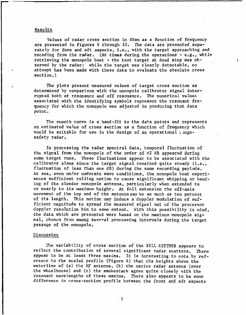
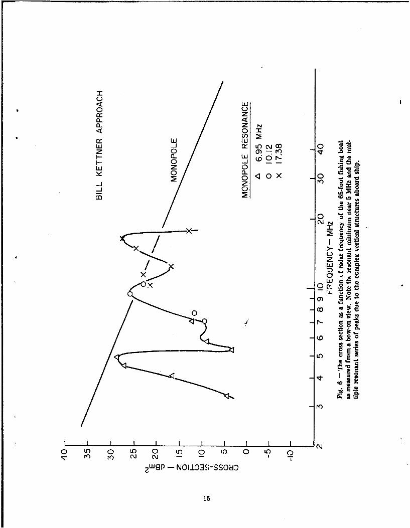
Values of radar cross section in dBsm as a function of frequencyare presented in Figures 6 through 10. The data are presented sepa-rately for fore and aft aspects, i.e., with the target approaching andreceding from the radar. (At times during the operations - e.g., whileretrieving the monopole boat - the test target at dead stop was ob-served by the radar: while the target was clearly detectable, noattempt has been made with these data to evaluate the absolute crosssection.)
The plots present measured values of target cross section asdetermined by comparison with the monopole calibrator signal inter-rupted both at resonance and off resonance. The numerical value&associated with the identifying symbols represent the resonant fre-quency for which the monopole was adjusted in producing that datapoint.
The smooth curve is a hand-fit to the data points and representsan estimated value of cross section as a function of frequency whichwould be suitable for use in the design of an operational [inge-safety radar.
In processing the radar spectral data, temporal fluctuation ofthe signal from the monopole of the order of ±2 dB appeared duringsome target runs. These fluctuations appear to be associated with thecalibrator alone since the target sigral remained quite steady (i.e.,fluctuation of less than one dB) during the same recording periods.At sea, even under moderate wave conditions, the monopole boat experi-ences sufficient rolling motion to cause significant whipping or bend-ing of the slender monopole antenna, particularly when extended toor nearly to its maximum height. At full extension the off-axismovement of the top end of the antenna may be as much as ten percentof its length. This motion may induce a doppler modulation of suf-ficient magnitude to spread the measured signal out of the processordoppler resolution bin to some extent. With this possibility in mind,the data which are presented were based on the maximum monopole sig-nal, chosen from among sevPral processing intervals during the targetpassage of the monopole.
Discussion
The variability of cross section of the BILL KETTNER appears toreflect the contribution of several significant radar scatters. Thereappear to be at least three maxima. It is interesting to note by ref-erence to the scaled profile (Figure 4) that the heights above thewaterline of (a) the HF antenna, (b) the marine radar antenna (overthe wheelhouse) and (c) the smokestack agree quite closely with theresonant wavelengths of these maxima. There also appears to be somedifference in cross-section profile between the front and aft aspects
7

of the boat. This effect may possibly be due to resonant interactionsbetween the radar-significant structures and their relative phase-delay along the line of sight.
In the case of TRB-IO, some structure can also be seen in thecross-section profile although it is not as prominent as with the BILLKETTNER. This might be expected in view of the more broadband RFnature of the TRB prominences.
The SOUTHERN COMFORT II shows the characteristics of a bulkreflector rather than one with resonant characteristics. It seemsclear that the HF antenna, which had long been out of service, was notgrounded, hence not playing a significant role in the overall crosssection.
In summation, several generalizations are reasonable:
1. A small surface craft whose highest vertical projection isan electrically-connected structure will produce a back-scatter which is closely representative of that of a monopoleof the same height; multiple structures will produce additiveeffects.
2. Small craft without significant vertical structures willdemonstrate small cross sections and be the most difficultto detect.
3. Based upon the three targets represented in this work, targetcross sections for the largest fishing craft begin fallingoff rapidly in the 5 to 7 MHz region, and the smallest boats'cross section will exhibit this behavior at even higherfrequencies. However, the sea clutter cross section falls offin this lower range of radar frequencies as well, althoughstill being a function of see state. Since target detectionsunder low external noise conditions would depend upon thesignal to clutter ratios encountered, the choice of a rangeof operating frequencies in the design of a range safety radaris not an obvious one at this time.
Finally, and as a matter of interest to other Navy users, it isinteresting to speculate that on the evidence of the BILL KETTNER asrepresentative of larger vessels with complex superstructures, a multi-frequency OTH radar might be capable of performing target classificationgiven an adequate catalogue of HF radar cross-section profiles.
8

REFERENCES
1. R.W.P. King, T.T. Wu, Scattering and Diffraction of Waves, HarvardUniversity Press, Cambridge, Massachusetts, 1959.
9

Ph to ra h o r^ the cres n n test ,o nl~ ~ e was ali rat o n f o r th e c r ss s ec tio n ne a sOp ol e W ic h W s U eaueets wsue
10

00
I 0 WWI,,
/ ~0
z w4o ~Lo
I 0
C'JN
/ ~z
- 0 c .
0 N-
020.W
2 0 WC "~
mI w 0 00
zw
N0 t 0 ') 0 LO 0 t'0 0 '0 0
ZU 8P -NOiZ03S-SSO8:

IL
0 NI
SCALE-FEET
B!LL KETTNERLENGTH OVERALL 65
MAX HEIGHT 54.5
Fit. 3 - A line drawing to scale of the largest fishing boat measured in these tests
12

I
SCALE-FEET0 5 10
SOUTHERN COMFORT ITLENGTH OVERALL 42'MAX. HEIGHT 29.5'
Fig. 4 - A line drawing to scale of a representative small fishing boatwhich was measured Ir, these tests
13

SCALE-FEET0 5 IOL , , ,, I
NAVAL UNDERSEA CENTERTORPEDO RETRIEVAL BOAT 10LENGTH OVERALL 65'MAX, HEIGHT 36'
Fig. 5 - A line '4zawing to scale of the Torpedo Retrieval Boat which was measured in these tests
14
Iw
0 ucr- z0-. Z N
< 01
w 0dz 0 a)-ro n
I-0 -J --
w Z 0 E0 0 -z re) O
C) 'o
Z
0 .- 2.35
a,
aD
Nr)
0 n 0~ Q O 0 '0 0 LO 0 LOC- r ~ C- - I
ZWP- NOIJ3JS-SSO80
15

Lii Lii
Lii 0wl 0
z0<
I-J 0
0L ,: Eý-
0~ di
a. 0
rl) o +
-~
?W B -NO±~3ssso
16E

Lu
Luu
I- z0 z 00
0- 0 Po-4 % 0
0 --LU 0r 0 -Nz 0 u 0 C\x+
0 0 CL
zz0'-
LL a
Q:,
+ ~-0
)Kt
sx
0 toC 0 it) 0 ito 0 to) 0 LO~~~.C~ T' r ~ N N
?W6P -NOI.L3S-SS08dC
17

/ N
z0<
< 0U0 0
< -)
oLL ox (612
0-0.1\ N0
E-)'
0-
LU6/z wLA-
XV
00
0 :00
<1 0
LA toL 0 LA) 0 LA to LAV) r'o N~ N~ - -- I I
zweP- NOU33S-SS080
18

Lii-J
wL 00 L 0wU 0 Iwd 0
0 LiJ 0U) r4)z
I-~ir
LI. p"~- CJCJr
.-J (D OD 0 C\000
ZZ
00
ui2
+ NL-
o ao (.0
to)
0 0C LO) 0 tfl 0 tf) 0 'CO 0ct r C'J C~j - - I
Zwgp -NOI110X-S-SSO80
19