AD-A021 139 AH-1 CANOPY - Defense Technical ... 139 DEVELOPMENT OF A BACKUP COVER FOR THE AH-1...
36
AD-A021 139 DEVELOPMENT OF A BACKUP COVER FOR THE AH-1 CANOPY CREMOVAL SYSTEM Donald R. Duffy Teledyne McCormick Selph Prepared for: Army Aviation Systems Command 31 October 1975 DISTRIBUTED BY: NaioalTchnca Iumfemtm Seric U. S. DEPARTMENT OF COMMERCE
Transcript of AD-A021 139 AH-1 CANOPY - Defense Technical ... 139 DEVELOPMENT OF A BACKUP COVER FOR THE AH-1...

AD-A021 139
DEVELOPMENT OF A BACKUP COVER FOR THE AH-1 CANOPYCREMOVAL SYSTEM
Donald R. Duffy
Teledyne McCormick Selph
Prepared for:
Army Aviation Systems Command
31 October 1975
DISTRIBUTED BY:
NaioalTchnca Iumfemtm SericU. S. DEPARTMENT OF COMMERCE

0 63158
La
REPORT USA AVSCOM TR-75-49
QDEVELOPMENT OF A BACKUP COVER=FOR THE AH-1 CANOPY REMOVAL SYSTEM
Donald R. Duffy
TELEDYNE MCCORMICK SELPH3601 UNION ROAD 4 J'XHOLLISTER, CA. 95023
12 DECEMBER 1975
FINAL REPORT APPROVED FOR PUBLIC RELEASE
DISTRILUTION UNLIMITED
Prepared for
U.S. ARWY AVIATION SYSTEMS C.3MANDP.D. ?ox 209 - AMSAV-PSSIST. LOUIS, mo. 63166
le*du~ by
NATIONAL TECHNICALIN-ORMATION SERVICE
US e.. of CoImmc eS5-4hold. VA 2 15I1

SICCUITY CLASSIFICATION OfP TNiSS dU . Due D .49.E___o_
I NUU T D0CUMEWTAT1ON PAGE Mme S omR"cTO ;U O*
I USA AVSCOM TR-75-49 _. " !a rIT.S (W lums) a. IArve " OF 90 ftIII P OVgugD
DEVELOPMENT OF A BACKUP COVER FOR 51275 REP -1TTHE AH-i CANOPY REMOVAL SYSTEM
TM2/S 660197
1 UO* Q 9;z COOTPACY r*AT Mr-.-Donald R. Duffy DAAJ01-75-C-0770 (PIC)
Teleuyne McCormick Selph3601 Union RoadHol.'ister, California 95023it. c.,,xT •,,,o .. ,€.N, OFIC WO MO ,OW IS t C A T9SU.S. Army Aviation Systems Command 31 October 1975P.O. Box 209, AMSAV-PSSI I. iIONPMIS O PA ...St. Louis, Missouri 63166 3b
I's 001100*6 £CEU MENI ZAXIMh~jh Z=w P Weai) I.SCW CLASSi. W 000 9Ws)
Unclassified
ft. 01TIS~mU1V0 StTmIMUT(- JIW* 1;. p;
Approved For Public Release Dis,-ribution Unlimited
_ ._________________________________________,______ -- -- . .." ---
18 5.PLIOU3TANy NOTES
AH-1 Canopy Removal SystemWindow Cutting Assembly•- Window Cutting Assembly Backup CovezWindow Cutting Assembly Shell
& LST RAC? &~a (Ceme" am,. to..W .etee ~Imi#* tow P by9WThis development program was funded to develop and test a backupcover for the Window Cuttinq Assemblies of the AH-i CanopyL f Removal System. The purpose of the backup cover is to extendthe service life of a Window Cutting Assembly which has develcpela crack in the polycarbonate retainer. The function of the back-'up cover (or shell) is to aid the damaged retainer in directing1! explosive energy and fragments from a Window Cutting Assemblyouýboard away from the crewmen. (cortinued)
DD 1473 01 TION or Iuove soI B It Unclassified
S4UIiC~~~ar~ oF -ru'ts

UnclassifiedSecurity Classification of this page (When !,ata Entered)
Blo-k 20. Abstract (Continued)
This report defines the desicn of the backup cover, the testingperformed to substantiate the desiqn and documents thesuccessful completion of this testinG. The testing includedtwenty-one (21) subscale tests to verify the environmentalcapability of the shell design and two (2) full-scale canopyremoval tests of the right side of the airframe from a simulatedcrash attitude.
Unclassified

INTRODUCTION
This program was funded under contract DAAJOl-75-C-0770 (PIG)
as a product improvement effort on the Window Cutting Assemblies
for the All-1 helicoptez Canopy Removal System. The principal
goal was to design, develop and test a shell type cover
for the Window Cutting Assemblies which would extend the
service life cf assemblies which had developed cracks in
the polycarbonate housing. The contract Work Statement
defines the design requirements and the testing philosophy.
The Work Statement is included as Appendix A.
HISTORY
The Canopy Removal System (CRS) for the A11-i Hrlicopter
as defined by Bell Helicopter Company Procuremert Specifi-
cation 209-030-711 has been in service for approximately
five (5) years. During this time a number of successful
escapes have been achieved in emergency situations. The
CRS was designed to provide a suitable means for rapid
ground egress from the helicopter in crash or emergency
landing situations. While the CRS has successfully provided
emergency egre- exits for crewmen in instances where the
system was call,!- upon, minor problems have developed in
the installation and maintenance of parts of the system
which have caused some concern. The main concern centers
around cracks which have developed in the polycarborate
(LEXAN) retainers of the installed Window Cutting Assemblies
(IWCA) which contains the cutting charge (LES).
The WCA is mounted around the periphery of the windows and
cdoors and contains the linear explosive which cuts the
transparency (to provide the emergency exit). The retainer
is the inboard surface of the WCA and resembles the window
--1--

SIISTORY (Continued)
rimolding around an automobile windshield. The purpose of theretainer is to position and maintain the linear explosive(LES) in contact with the window and to direct the explosive
energy and window fragments outboard when the system isfunctioned. The retainer is attached to the door or window
frame by means of rivets.
The cracks which have been detected in the installed retainersare caused by two (2) problems. One is a crack in a section ofretainer which has been highly stressed during installation to
force it to conform to the canopy sill and support structure.
This type of crack is usually found around the corners of thewindow or emanating from mounting rivet holes. The second type
of crack is found in sections of retainer which have been exposedto solvents such as naphtha or acetone. Cracks cf this type
usually develop in stressed areas around rivet holes.
The concern over these retainer cracks deals with the abilityof the cracked retainer to direct the explosive energy andwindow fraoments outboard away from the crewman. Whilethere are no reported cases of injury to cr-wmen caused
by inboard traveling fragments, cracked retainers certairlylower the safety factor prohibiting this problem. As a
temporary fix, in some instances, sheet metal doublers have
been riveted over the cracked area of a retainer to avoidrepldcing the WCA.
The purpose of this program was to develop and test a suitable
backup cover or shell to be installed over the inboard surface
of a cracked a'etainer. The shell was reauired to exhibit thesame cosmetic appearance as the original retainer except that
it nmay be segmented into up to four sections for ease ofinstallation. The shell was designed to be riveted on thecanopy support structure over the original WCA.
-2-

No-Pow
HISTORY (Continued)
r_ The test program consisted of a subscale series and a full
"scale window removal phase. The subscale phase consisted of 21
assemblies which utilized retainers which had been cracked
in various maziers, subjected to various solvents and
tested at temperature extremes. The full scale tests were
perforated in a mockup of the forward canopy fuselage ofthe AH-l. Two tests were conducted where the right sidewindows were ejected from a simulated crash attitude.
16mm motion picture coverage of these two tests was performed
in accordance with the Work Statement.
SUBSCALE TESTS
A series o, tests on subscale window cutting assemblies
with backup shells was devised to simulate worst case
conditions of retainer cracks, solvent deterorization
and functioning temperature. The test objective was to
evaluate the ability of .062 thick DKE-450 (acrylic/PVCalloy) shells to support damaged retainers and prevent
inboard directed fragments during functioning of thesubscale WCA.
The subscale WCA's with shells were fabricated according
to Figure 1. Tae retainers were intentionally damaged in
two ways. 11alf the retainers were cut through with a saw
while tne renmaining retainers were treated with acetone
until they cracked. To verify the solvent resistance of
the DKE-450, each subscale shell was wiped with either
acetone, naphtha or M-142. Examples of retainer cracks
are shown in Figure 2 with the saw cut at the top of the
photograph and the acetone crack at the bottom. Figure
3 illustrates a typical t est specimen.
-3-

CO4
nw -, '
INaa
z C6.
mop1!t-

6h4
u
E-4
(14

IN
•_• _ '- • .••,•,• • I . . ...• . .. I.L •, • ... ...
SI
1*
*1
-6-

SUBSCALE TESTS (Continued)
The functional test results are presented in Table Ifor the 21 subscale specimens. The largest number of
samples (11) was tested at 160°F since the high temperature
was deemed the more severe test due to the nearness
of the softening temperature of the DKE-450. One sample
was sustained at 180OF for 72 hours before dropping to
160°F for the functional test to verify the high temperature
storage capability of the DKE-450.
The test results show that all subscales performed
satisfactorily in that the acrylic panel was severed and the
DKE-450 shell did not fragment or allow the fragments to be
directed inboard. One shell cracked when fired at low
temperature but no fragments were ejected or allowed
to pass inboard. Cracking of the retainer or shell
is acceptable as long as fragments are not released
which could injure a crewman.
FULL SCALE TESTS
Two full scale window removal tests were conducted subsequent
to verification of the DKE-450 material in the subscale
tests. The tests were performed utilizing a forward fuselage
section fitted with a gunner windcw and a pilot door. The
WCA's used were each liberally treated with acetone to cause
cracks in two one foot long sections. The DKE-450 shells
were fitted over the damaged WCA's and both of these
riveted to the canopy support structure. Before functioning
of the WCA's, the fuselage section was tilted at 200 on
one side to simulate a crash attitude.
-7-

r
J TABLE 1. SUBSCALE SHELL TESTS
InducedTemperature Crack Solvent
(F) Type Treatment Test Results
160 Acetone Acetone Satisfactory Performancea160 Acetone Acetone Satisfactory Performance
160 Acetone Naphta Satisfactory Performance
160 Acetone Naphta Satisfactory Performance
160 Acetone M-142 Satisfactory Performance
160 Saw Acetone Satisfactory Performance
160 Saw Acetone Satisfactory Performance
160 Saw Naphtha Satisfactory Performance
160 Saw Naphtha Satisfactory Performance
160 Saw M-142 Satisfactory Performance1 6 0 b Acetone Acetone Satisfactory Performance
-65 Saw Acetone Satisfactory Performance
Cracked Shellc
-65 Saw Naphtha Satisfactory Performance-65 Acetone M-142 Satisfactory PerformanceAmb Acetone Naphtha Satisfactory PerformanceAmb Acetone Naphtha Satisfactory Performance
Amb Acetone Mh-142 Satisfactory Performance
Amb Saw Acetone Satisfactory Performance
Amb Saw Acetone Satisfactory Performance
Amb Saw Naphtha Satisfactory Performance
Amb Saw Naphtha Satisfactory Performance
SSha

I
TABLE 1 (Continued)
J FOOTNOTES
a"Stretched acrylic test panel separated from frame and
shell remained intact.
bReferenced test unit conuc .ioned at ld10F for 72 hours before
testing at 1600 F.
CShell remained intact but exhibited a crack over 30% of
length.

PRIMARY TEST
The first full scale test specimen is illustrated in Figure 4,
showing the gunner window and pilot door with window, WCA and
shells installed. The fit and appearance of the gunner
window shell is shown in Figure 5, while Figure 6 illustrates
the pilot door shell. Figure 7 shows in detail Lie canopy
support structure between the gunner window and the pilot
door. Note the joint between the shell segments visible in
this view.
The two WCA's on one side of the canopy structure were
functioned simultaneously. Figure 8 catches the action
an instant after detonation of the WCA. Note the position
of engineer showing safety to external personnel. The
engineer was positioned 10 feet forward and 10 feet to the
side of the WCA.
Both the gunner window and the pilot door transparencies
were severed from the support structure, although part of
the pilot door transparency remained propped upright as
shown in the motion picture coverage. The motion picture
shows the effort required to remove the portion of trans-
parency blocking thu pilot's exit.
One anomally occurred as a result of this test; part of
the shell was ripped loose from the canopy support
structure and dropped across the exit. This situation
is shown in Figures 9 and 10. The slell did not crack
or fragment, but was ripped loose at one end of one
segment. To meet schedule requirements, only approximately
one-third of the standard number of rivets were used.
Normal rivet spacing is two (2) inches; the test installation
SL spacing was approximately six (6) inches.
- 10-

A& A
- *mimM-7
2t -E
<4 -4-
-,0-
~"
-- of

WARM:&' -½- :1 ~---- ~~- ~ ~ --
;p i _
MIN
U'I!kzN
__ t In
43 M3ýT R --4
- -,-Q;0- ini___ __~ -- ~Ž-- M5
C. -No-. r ~-
12--

iqp
-- m Yo M
4 _ Mt
~lmevRM-MyýW~
c~am
VI, W-A
~~-MW
~vg
-- W
ev~

17 f-
....... 9.
-
4 ;1AWN____
-
-&-rb t
~IMM
-sit-
MOW -7
In-S
~~y-~
r- - - l -k4-
FI~tRZ 7 SHLL& INSTALLATION

_________ 01F
Sw____
4mRR
x=
&gmgg-
ala
gtt_
AN ; J W1
VttR liw ,-N,
AMyr-
1-17 _11 ' 't t _
t*4t
±¶S'-4- *~~r W ~<0~- -
c ~
-. =.,~~__________ s$~' -j~*-ME~A-A t ý -
-ý -o ~ t~- ___ E~ 3~z-e AM--"-"'-M
NM____ -aA k _WA-C- -~--M7 -r~ ~$A~jP- 44-.4, 9k".
Z-0 F4 L
-~~_ - N týitR4< %WVA - "- .,a----
___ ~ r=K-7
_____ ___ _____4m
ZPM:___-5-.~tr--)r' __
~~~~~ZL '. 1,44 t~f $ t¾
5_ -' exz~~Fn p R 2Q~l S4'A

544
I4%
Up
1U.
V 4,
MA - -ow
kg;,
A ~ i Arg g-'
B~r -ON_____ al_______

4MN.
ý W-S
'-ko~ zk'V -E
~Wtz
- ~4 ~4 ~~&
RM 'A
-gs
"'*a __ __
/ 44r
-- 9-1-k
'MWp-S
U"U
4 7-5

FINAL TEST
Installation of the WCA's and shells for the second and
final full-.scale test was identical to the first setup
with the exception of the rivet spacing. Rivet spacing
on the WCA and shell installation was two (2) inches.
The installation is documented in Figure 11 for the
gunner window and Figure 12 for the pilot door.
The WCA's were initiated as in the first test and the
action is captured in Figure 13. The action is stopped
an instant later than in the first te4t. Both windows-;ere cleanly removed providing two unobstructed exits
from the airframe as illustrated in Figure 14.
The shells remained intact without cracks or pulling
through the rivets as in the first test. Figure 15
shows the post test condition of the gunner shell while
the pilot docr shell condition is documented in Figure 16.
Motion picture coverage of both tests was successfully
obtained and has been edited intc one 16mm film consisting
of approximately 100 feet of film. The film contains
pretest views of the shell installation, the canopy
removal event, and post test coverage of shell condition.
The motion picture is a part of this final report.
LESIGN
The shell desiqn proposed and verified through subscale
and full-scale testing consists of vacuum formed DME-450
acr-y ,ic/• • a~loy) conforming to the inboard surface
shape of thc WCA retainer. DKE-450 is a DuPont plastic
rmateriaA. tnat is easily vacuum formed and has mechanical
properties sirzilar to polycarbonate.
Is-

S t -- '--t
-a -1 -- i-g ýe K ,
'M Uz-g L -
MrN 2
rm Ajr~z-4 '-r- -92Ž> ~ : ~ C. _- t2
~ ~- A-, -NuM-,
-- -
-Q -. J- 0
Vo Oe zt-W-
M4RA
LIEAflu a
* ~ ~ ~ ~ ~ ~ ~ ~ ~ ~ ~ ~ ~ 1 ýM$ ~FGR 1 UNRWNO SELISALTOJo, R09u A

rAM
~~ONAl5MWmi
NEN
-~ Zs~Z -5..
_MU3I
SOE 1ý MEN
-- 20-IWI

-7-A
N~ -5- -2
-4- -='-~ -- -- -~ --- 4- --Z Iml, c__n
4--5
7ýkr7, 45~ -~ - - _
-75 2F --f
-~~ -ýW -
ozv 44----- V-
N- -pM AF-
V 5 --- 4ý_F - - 4- _--
-- W- -PV
-4~~~~~~~~~~~~~ R~~~-.-r- ~ - -- A'' ---- --- Of- --~p _ 44--- 4 4~-4V, -- 4-~-3 4'-2N -
V44-4~- --- 4---
;t- -- 4RI-NES~-~-4
--- w--_
-~ ~ ~ R -- i-ik-V--', AMA
-'n-r -pF,i27 NE
---- -3 -4
- ~ ~ ~ ~ ~ ~ ~ ~ ~ ~ ~ ~ ~ ~ ~ ~ S -ý -4--ýF!. - -- 4 4 ---- --- 44---.- ',ý-
__~~~ -A--- ~ p---~--~ z
vm.4 -'-44-

- P - - - aM;7- __________________________
IMP'-
-4 4 ~ a-a ~ a AMR.
-- --- as' -~ a4 '~ Ž~' ½~- -
-a 2~ M,, -
'4-44- 4 "~ ~ 4 4-'- -~ -~ Ar a
-N---M-=~~ a ~ at2~ -- 4-'~$- 4 t--
I M - ~ ~ 4--44 5 3 -- '4-4-4 -aA - --.- 4w4
'-4-- 9'MOM N'-4_ K- "-5 .--.---- 4 '
- ---- 45r~~~-ý---gtx3
s ýos->W4-=v -or-
-V-W¶ 34-4-44-- >-4-----lr-= -
-_ 7a
-.- -
0- "A4--- 34%5a¶ ~ a
-7 ss3-44 a--, ~ --
-5 -- t- a454--1As'-~4c>- a~
44-'-~J'4--344 ~ ~ 3
4-4-443
J 42 - >4# 4

24--
-i -;_ 50 4R5ý
M-3~ 2- -"M
45 .
0,
_M 42 .-.- s
22 ~ -
Ell~
-- --
m
ýi !Pi
M~ 4tvz g ý-- -- '
'M9 -g -
g, ~ -~--
Ri~
R'~ 01 wONE nfw~a~fOAM4 72-3

- -~'~ - - -- -- -4
, -~ -' -~~.
- -~ -''
- ~ - - - - - - - - - - - - _ _ _ _ _ _ _ _ _ __R
iL -R~ -e M-0
0. '---
'4~ r-u _ag_
- -c a -
__qý Y--B4:1
gg -- 4-'--- M-.MMMý
____'g m '"-
'R-A
MM- ®R -4 - --
~'-4n~ 1 r-
- "~f
UR
3 -,MR
MM ft-,'-
VON T' 4-
- M~
c-, AAWT:V'
122-Se4

DESIGN (Continued)
Shells were formed from flat sheets of 0.062 thick
DKE-450 and trimmed to fit the appropriate WCA and
associated canopy support structure. Each shell con-
sists of four segments which, when fitted to the WCA,
provide complete coverage of the WCA with the exception
of the doubler area and a maximum gap of 0.25 inch
between segments.
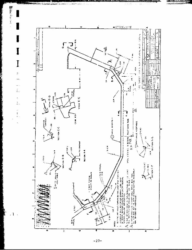
The TMc/S fabrication drawing for the shells is included
as Drawing Number 815478.
CONCLUSIONS
The subscale environmental tests combined with the full-
scale canopy removal tests have demonstidted the shells
are capable of performing their intended purpose of
supporting a damaged retainer during functioning of the
WCA. The shells have been shown to prohibit the release
of fragments from the WCA in an inboard direction.
The subscale test series has demonstrated that the DKE-
450 shells are able to function properly over the tempera-
ture extremes defined for the canopy removal system by
Bell Helicopter Specification 209-030-711. The shells
have also been shown to withstand contact with the same
solvents that normally damage the WCA retainer.
As a result of this successful test program, TMc/S
recommends the installation of four (4) sets of shells
in AH-I Helicopters for actual service use and evaluation.
-25-

l Aa
'lD
'0fol . 'I< - lI,,,r- rr, ,-,.3.i '
" " ""'!11:!- U' c '! I-
t ; I i: , a II :. .
* . I..
I II
I'
4, Ii
400
N.w'
-26-,•.• -
II.11.i-ii 2
-4 1'- ;. -
U 4� f T�
.4 C,
r -
ii.11 j % 4
II! �, .% 0�n4 go
* -
/ ¶1I ___ ':�''�4- .11 N
t * 4:� - � L�..A:.I
�- S.- 'HL� �
00,
/ I) a
4
(� \\ �IL
�-�'� - S -
-,� .j�
�
� ftA�0
) 4--
3:" '�
'I -r --
- p.'
4,
Ii .. ,-
'Jrft 4 4- - -'4 -... �.
I..,..o U 0 4

I;0 U .E:�.�-;-�I 4
�iII -
-Ii � a 7iii .� is
HI4- H 4,-- � a �
4e-�Z
A �a.,- A
- -.- � 4 ii 4�'4.4 . -,
H � / �.? 4, 04,
�
liii
a
''-'(41 i.4 I 4-
'- �.
;� 3 t�-. ;
�.? 4.
a -' �
� a �4-.. . 0 - ,*,,. ..
a
af a4%�
I�4, C --'� a2 -� � 2
a00-
C- 1 a
*1 -� � t-, 2
S
4.
-0 o� �
- k-d '.4 4- -,
>� - -' a.e z' a -
'-4-- �1,4- -J 415' �
ii-' 3*� -�
31 -,
�- 4 I
� 1 ,e � 0' .- O-0
-. Z . .�-.
C U * I 4
-26-

* IL1
.......... L
/ 'S' i .1i "- 'j,
a4Q
ItI
"a -- 4:" .:,
SI ,_J"" ">
*1 -'
00 16
a I * ... .
"C I *<
-29-

Alid
A~lA' 0.
-.0
-30-1
APPENDIX A
STAIZMENT OF WORK
The Contractor, as an independent contractor and not as an
agent or employee of the Government, shall provide
engineering services to deliver Window Cutting Assembly (WCA)Backup Retainers for AH-I Canopy Removal System (CRS).
i. Fabricate two each segmented (door and window sets)
backup covers for the pilot's door and gunner's window. A
set will consist of a minimum of four sections which will
meet at the corners of the door. There will be no inter-
ference with the present CRS. The contractor is responsiole
for securing the sections of the backup cover to the door
with an acceptable fastener which has the approval of Army
Engineering. The segmented backup will be approximately
0.40 fiberglass or an equivalent material which passes all
of the test criteria. The weight will not exceed one pound
per door. The space between the corners will not exceed
0.25 inches. The backup covers and WCA will conform to thepresent Bell Helicopter Company Procurement Specification
209-030-71 Rev. D, and Teledyne McCorminc Selph (TMc/S)
Quality Test Procedure 813656, Rev. A. The mockup airframe ofthe F1D canopy fuselage will be used for motion pictures to
depict actual anticipated crash landing of the aircraft.
These photos sequences will be in the final report. The full
scale door firing will have at least a foot section applied
with several caustic solvents on the LEXAN WCA. These fourfirings are to demonstrate integrity when the backup cover
is used.
2. Fabricate 20 subscale WCA qual specimen assemblies similar
' L to P/N 150224 (18 inch test with linear explosive substance
against a simulated canopy stretched acrylic).
-31-

I
Ii APPENDIX A - STATEMENT OF WORKW (Continued)
a. This portion of the development will utilize material
DKE 450 or equivalent.
b. The twenty subscales with DKE 450 (or equivalent)
backup covers will be fired at the temperature extreme
L" specified in BHC Procurement Specification 209-030-711
-- Rev. D, per the TMc/S Ouality Test Procedure 813656,
I. Rev. A.
c. Prior to subjecting the subscales to the test enviorn-
ments they will be wiped with various caustic solvents
to determine if cracking or crazing occurs and if the
fragmentation retention of shrapnel is impaired. A
selection of material shall be made upon successfully
passing the development phase.
3. Fabricate one complete shipset (a complete shipaet consists
of TMc/S P/N 814280-101, -102, -103, -104) of WCA with silver
sheathed pyrotechnic using the selected material This WCA
shipset will be installed on a Cobra Helicopter to provide
service life data. The new material for a new WCA will not
* exceed the weight of the LEXAN WCA. The WCA shipset shall be
* • delivered to Fort Rucker, Alabama. Four (4) shipsets of backup
covers (a complete shipset consists of TMc/S P/N 815478-1, -2,
-3 and -4) shall be fabricated. These backup covers shall be
_.. •c a'::t w2ie'; "<a::. r:,:c/'s .ill -rovido a liaison
r .... :•, ' ... Gc i. :i Q,,:.j ornoc! installation at a
"site selected by the Army. T~c/S will provide written instruc-
tions for installation of the backup retainer WCA. A target"goal is to reduce the weight of the present CRS without reducing"system integrity.
4. The service life of the WCA will have a design goal service
life of at least ten (10) years.
e- Av',abl3.-st