
Acura 2.5TL 3.2TL (1995-1998) Body Repair Manual
152
Preparation of Work Description 1-2 . . . . . . . . . . . . . . . . . . . . . . . . . . . . . . . . . . . . . . . . . Checkpoints 1-3 . . . . . . . . . . . . . . . . . . . . . . . . . . . . . . . . . . . . . . . . Correction of the Damaged Area 1-4 . . . . . . . . . . . . . . . . . . . . . Measurement (Excluding small damage) 1-6 . . . . . . . . . . . . . . Positioning Jigs 1-7 . . . . . . . . . . . . . . . . . . . . . . . . . . . . . . . . . . . . .
-
Upload
candieapple -
Category
Documents
-
view
339 -
download
3
description
Original Acura 2.5TL / 3.2TL (1995-1998 model) Body Repair Manual. Total 154 pages
Transcript of Acura 2.5TL 3.2TL (1995-1998) Body Repair Manual
Preparation of Work
Description 1-2. . . . . . . . . . . . . . . . . . . . . . . . . . . . . . . . . . . . . . . . . Checkpoints 1-3. . . . . . . . . . . . . . . . . . . . . . . . . . . . . . . . . . . . . . . . Correction of the Damaged Area 1-4. . . . . . . . . . . . . . . . . . . . . Measurement (Excluding small damage) 1-6. . . . . . . . . . . . . . Positioning Jigs 1-7. . . . . . . . . . . . . . . . . . . . . . . . . . . . . . . . . . . . .

Welding Methods / Repair Tools
Spot Welding 2-2. . . . . . . . . . . . . . . . . . . . . . . . . . . . . . . . . . . . . . . Gas Welding 2-4. . . . . . . . . . . . . . . . . . . . . . . . . . . . . . . . . . . . . . . . Carbon Dioxide Arc Welder (MIG Arc Weld) 2-5. . . . . . . . . . . Examples of Repair Tools 2-6. . . . . . . . . . . . . . . . . . . . . . . . . . . .

General Information
Zinc-plated Steel Plate Repair 3-2. . . . . . . . . . . . . . . . . . . . . . . . Door and Bumper Reinforcement 3-4. . . . . . . . . . . . . . . . . . . . .

General Information
Construction 4-2. . . . . . . . . . . . . . . . . . . . Front Fender
Replacement 4-3. . . . . . . . . . . . . . . . . Front Bulkhead
Description 4-4. . . . . . . . . . . . . . . . . . Mass Production Body Welding Diagram 4-4. . . . . . . . . . . . . Replacement 4-5. . . . . . . . . . . . . . . . .
*Front Wheelhouse/Damper HousingDescription 4-8. . . . . . . . . . . . . . . . . . Mass Production Body Welding Diagram 4-8. . . . . . . . . . . . . Replacement 4-10. . . . . . . . . . . . . . . .
*Front Side FrameDescription 4-14. . . . . . . . . . . . . . . . . Mass Production Body Welding Diagram 4-14. . . . . . . . . . . . Replacement 4-16. . . . . . . . . . . . . . . .
*Front Side Outrigger/Front Side Extension
Description 4-21. . . . . . . . . . . . . . . . . Mass Production Body Welding Diagram 4-21. . . . . . . . . . . . Replacement 4-23. . . . . . . . . . . . . . . .
*Front Pillar (Outer Panel)Description 4-26. . . . . . . . . . . . . . . . . Mass Production Body Welding Diagram 4-26. . . . . . . . . . . . Replacemen t 4-27. . . . . . . . . . . . . . . .
*Windshield LowerDescription 4-30. . . . . . . . . . . . . . . . . Mass Production Body Welding Diagram 4-30. . . . . . . . . . . . Replacement 4-30. . . . . . . . . . . . . . . .
Side Sill/Outer PanelDescription 4-32. . . . . . . . . . . . . . . . . Mass Production Body Welding Diagram 4-32. . . . . . . . . . . . Replacement 4-33. . . . . . . . . . . . . . . .
Roof PanelDescription 4-36. . . . . . . . . . . . . . . . . Mass Production Body Welding Diagram 4-36. . . . . . . . . . . . Replacement 4-37. . . . . . . . . . . . . . . .
Rear Side Outer PanelDescription 4-40. . . . . . . . . . . . . . . . . Mass Production Body Welding Diagram 4-40. . . . . . . . . . . . Replacement 4-41. . . . . . . . . . . . . . . .
Rear PanelDescription 4-45. . . . . . . . . . . . . . . . . Mass Production Body Welding Diagram 4-45. . . . . . . . . . . . Replacement 4-46. . . . . . . . . . . . . . . .
Rear FloorDescription 4-49. . . . . . . . . . . . . . . . . Mass Production Body Welding Diagram 4-49. . . . . . . . . . . . Replacement 4-50. . . . . . . . . . . . . . . .
Rear Floor Cross MemberDescription 4-55. . . . . . . . . . . . . . . . . Mass Production Body Welding Diagram 4-55. . . . . . . . . . . . Replacement 4-56. . . . . . . . . . . . . . . .
*Honeycomb Floors (2.5TL)Replacement 4-58. . . . . . . . . . . . . . . .
Items marked with an asterisk (*) include SRS components; special caution is required when servicing.
Body Welding Symbols

The symbols in the mass production body welding diagrams and in the replacement illustrations carryfollowing meaning:
: Spot welding: MIG welding
NOTE: The welding symbols in the illustrationsdon't show exact welding locations. For exactwelding locations, refer to the mass productionbody welding diagrams.
Spot weldingMIG welding2-plate welding3-plate welding4-plate welding
P= Spot welding pitchUnit: mm (in)
( ) The number of the spot welding
Cross Section of Body and Sealants
2.5 TLEngine Compartment/Front Wheelhouse 5-2. . . . . . . . . . . . . . Front Pillar Inner Panel, Front Floor/Rear Floor and Roof Panel 5-3. . . . . . . . . . . . . . . . . . . . . . . . . . . Outer Panel, Rear Floor/Rear Panel, Rear Wheelhouse 5-4. . . . . . . . . . . . . . . . . . . . . . . . Under Floor/Frame 5-5. . . . . . . . . . . . . . . . . . . . . . . . . . . . . . . . . . Hood, Door, Trunk Lid 5-6. . . . . . . . . . . . . . . . . . . . . . . . . . . . . . .
3.2 TLEngine Compartment/Front Wheelhouse/Under Floor 5-7. . . . . . . . . . . . . . . . . . . . . . . . . . . . . . . . . . . . . . . . . Spot/Mastic Sealers 5-8. . . . . . . . . . . . . . . . . . . . . . . . . . . . . . . . .
Body Dimensional Drawings
Upper Body Measuring DimensionsEngine Compartment2.5TL 6-2. . . . . . . . . . . . . . . . . . . . . . . . . . . . . . . . . . . . . . . . . . . . 3.2TL 6-3. . . . . . . . . . . . . . . . . . . . . . . . . . . . . . . . . . . . . . . . . . . . Passenger Compartment 6-4. . . . . . . . . . . . . . . . . . . . . . . . .
Under Body Measuring Dimensions2.5TL 6-5. . . . . . . . . . . . . . . . . . . . . . . . . . . . . . . . . . . . . . . . . . . . 3.2TL 6-6. . . . . . . . . . . . . . . . . . . . . . . . . . . . . . . . . . . . . . . . . . . .
Opening Repair Chart 6-7. . . . . . . . . . . . . . . . . . . . . . . . . . . . . . .
Frame Repair Chart2.5TL 6-8. . . . . . . . . . . . . . . . . . . . . . . . . . . . . . . . . . . . . . . . . . . . 3.2TL 6-10. . . . . . . . . . . . . . . . . . . . . . . . . . . . . . . . . . . . . . . . . . . .
Rust-preventive Treatments
General 7-2. . . . . . . . . . . . . . . . . . . . . . . . . . . . . . . . . . . . . . . . . . . . . Diagram 7-3. . . . . . . . . . . . . . . . . . . . . . . . . . . . . . . . . . . . . . . . . . . . Area to be Covered by Anti-rust Agents 7-4. . . . . . . . . . . . . . Undercoating Diagram 7-10. . . . . . . . . . . . . . . . . . . . . . . . . . . . . . .

Body Paint Repair
Color Chart Painting Specifications 8-2. . . . . . . . . . . . . . . . . . Paint
General 8-3. . . . . . . . . . . . . . . . . . . . . . . . . . . . . . . . . . . . . . . . . . Intermediate Coat Colors 8-4. . . . . . . . . . . . . . . . . . . . . . . . . Paint Refinishing 8-5. . . . . . . . . . . . . . . . . . . . . . . . . . . . . . . . . Defects and Refinishing Processes 8-5. . . . . . . . . . . . . . . . Refinishing Processes 8-6. . . . . . . . . . . . . . . . . . . . . . . . . . . . Refinishing Procedures 8-7. . . . . . . . . . . . . . . . . . . . . . . . . . .
NH-585P (Cayman White Pearl) PaintRefinishing Procedures 8-11. . . . . . . . . . . . . . . . . . . . . . . . . . . Color Matching 8-13. . . . . . . . . . . . . . . . . . . . . . . . . . . . . . . . . .
Soft Chipping Guard Primer CoatGeneral 8-15. . . . . . . . . . . . . . . . . . . . . . . . . . . . . . . . . . . . . . . . . . Coating Diagram 8-16. . . . . . . . . . . . . . . . . . . . . . . . . . . . . . . . . Repair Material and Tools 8-17. . . . . . . . . . . . . . . . . . . . . . . . . Coating Procedures 8-18. . . . . . . . . . . . . . . . . . . . . . . . . . . . . .
Resin Parts Paint Repair (Exterior)
Types and Materials of Exterior Resin Parts 9-2. . . . . . . . . . . Polypropylene (PP) Resin Parts
General 9-3. . . . . . . . . . . . . . . . . . . . . . . . . . . . . . . . . . . . . . . . . . Repair Materials and Tools 9-3. . . . . . . . . . . . . . . . . . . . . . . . Refinishing Porcesses 9-5. . . . . . . . . . . . . . . . . . . . . . . . . . . . Repair Procedures 9-6. . . . . . . . . . . . . . . . . . . . . . . . . . . . . . . Refinishing Procedures 9-7. . . . . . . . . . . . . . . . . . . . . . . . . . .
ABS/PC Resin PartsGeneral 9-12. . . . . . . . . . . . . . . . . . . . . . . . . . . . . . . . . . . . . . . . . . Repair Materials 9-12. . . . . . . . . . . . . . . . . . . . . . . . . . . . . . . . . . Repair Procedures 9-13. . . . . . . . . . . . . . . . . . . . . . . . . . . . . . . Refinishing Procedures 9-13. . . . . . . . . . . . . . . . . . . . . . . . . . .
Glossary 9-15. . . . . . . . . . . . . . . . . . . . . . . . . . . . . . . . . . . . . . . . . . .
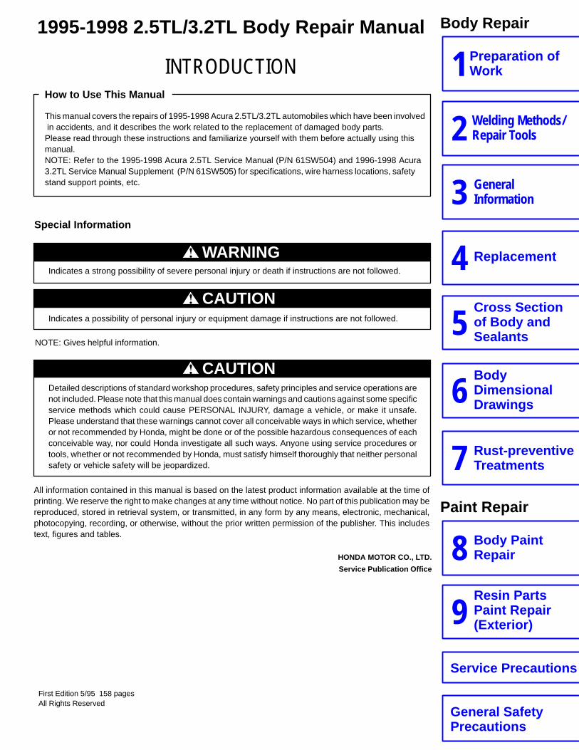
CAUTIONDetailed descriptions of standard workshop procedures, safety principles and service operations arenot included. Please note that this manual does contain warnings and cautions against some specificservice methods which could cause PERSONAL INJURY, damage a vehicle, or make it unsafe.Please understand that these warnings cannot cover all conceivable ways in which service, whetheror not recommended by Honda, might be done or of the possible hazardous consequences of eachconceivable way, nor could Honda investigate all such ways. Anyone using service procedures ortools, whether or not recommended by Honda, must satisfy himself thoroughly that neither personalsafety or vehicle safety will be jeopardized.
CAUTIONIndicates a possibility of personal injury or equipment damage if instructions are not followed.
WARNINGIndicates a strong possibility of severe personal injury or death if instructions are not followed.
Special Information
All information contained in this manual is based on the latest product information available at the time ofprinting. We reserve the right to make changes at any time without notice. No part of this publication may bereproduced, stored in retrieval system, or transmitted, in any form by any means, electronic, mechanical,photocopying, recording, or otherwise, without the prior written permission of the publisher. This includestext, figures and tables.
This manual covers the repairs of 1995-1998 Acura 2.5TL/3.2TL automobiles which have been involved in accidents, and it describes the work related to the replacement of damaged body parts.Please read through these instructions and familiarize yourself with them before actually using thismanual.NOTE: Refer to the 1995-1998 Acura 2.5TL Service Manual (P/N 61SW504) and 1996-1998 Acura 3.2TL Service Manual Supplement (P/N 61SW505) for specifications, wire harness locations, safety stand support points, etc.
How to Use This Manual
NOTE: Gives helpful information.
HONDA MOTOR CO., LTD.
Service Publication Office
First Edition 5/95 158 pagesAll Rights Reserved
Preparation of Work1Welding Methods/ Repair Tools2GeneralInformation3
Replacement4Cross Sectionof Body andSealants5
INTRODUCTION
Body Repair
BodyDimensionalDrawings6
Rust-preventiveTreatments7
Body PaintRepair8Resin PartsPaint Repair(Exterior)9
Paint Repair
Service Precautions
General SafetyPrecautions
1995-1998 2.5TL/3.2TL Body Repair Manual

Preparation of Work Description
• Most monocoque bodies are composed as a single unit by welding together pressed parts made of steel plates which come ina variety of different shapes and sizes. Each part is responsible for displaying a certain strength and durability in order that itmay play its role in meeting the functions of the body as a whole.
Damage to the exterior of the body can be inspected visually, but where there has been an external impact, it is necessary to inspectthe extent of the damage. In some cases, the deformation has spread beyond the actual areas which were in the collision and sothis has to be inspected closely.
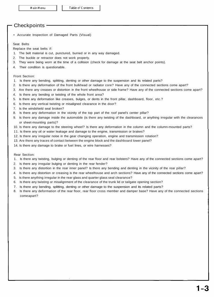
Checkpoints• Accurate Inspection of Damaged Parts (Visual)
Seat BeltsReplace the seat belts if:1. The belt material is cut, punctured, burned or in any way damaged.2. The buckle or retractor does not work properly.3. They were being worn at the time of a collision (check for damage at the seat belt anchor points).4. Their condition is questionable.
Front Section:1. Is there any bending, splitting, denting or other damage to the suspension and its related parts?2. Is there any deformation of the front bulkhead or radiator core? Have any of the connected sections come apart?3. Are there any creases or distortion in the front wheelhouse or side frame? Have any of the connected sections come apart?4. Is there any bending or twisting of the whole front area?5. Is there any deformation like creases, bulges, or dents in the front pillar, dashboard, floor, etc.?6. Is there any vertical twisting or misaligned clearance in the door?7. Is the windshield seal broken?8. Is there any deformation in the vicinity of the top part of the roof panel's center pillar?9. Is there any damage inside the automobile (is there any twisting of the dashboard, or anything irregular with the clearances
or sheet-mounting parts)?10. Is there any damage to the steering wheel? Is there any deformation in the column and the column-mounted parts?11. Is there any oil or water leakage and damage to the engine, transmission or brakes?12. Is there any irregular noise in the gear changing operation, engine and transmission rotation?13. Are there any traces of contact between the engine block and the dashboard lower panel?14. Is there any damage to brake or fuel lines, or wire harnesses?
Rear Section:1. Is there any twisting, bulging or denting of the rear floor and rear bolsters? Have any of the connected sections come apart?2. Is there any irregular bulging or denting in the rear fender?3. Is there any distortion in the rear inner panel? Is there any bending and denting in the vicinity of the rear pillar?4. Is there any distortion or creasing is the rear wheelhouse and arch sections? Have any of the connected sections come apart?5. Is there anything irregular in the rear glass and quarter glass seal clearance?6. Is there any twisting or misalignment of the clearance of the trunk lid or tailgate opening section?7. Is there any bending, splitting, denting or other damage to the suspension and its related parts?8. Is there any deformation of the rear floor, rear floor cross member and damper base? Have any of the connected sections
come apart?
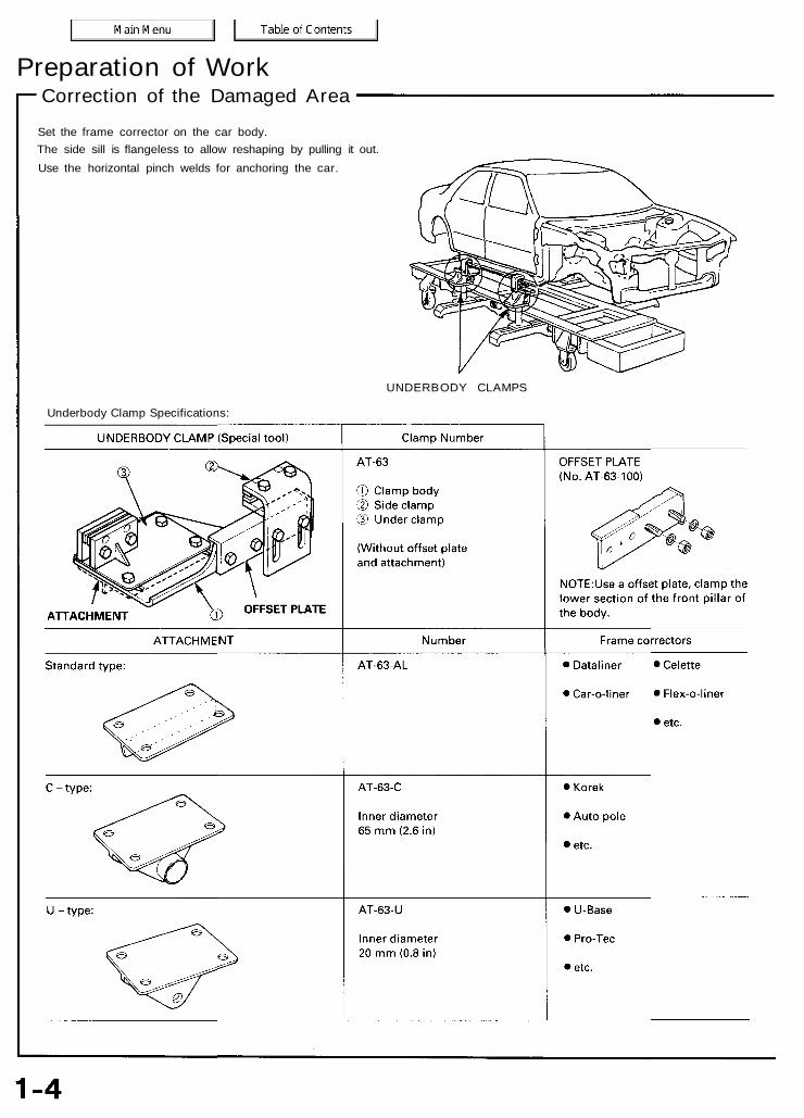
Preparation of WorkCorrection of the Damaged Area
Set the frame corrector on the car body.The side sill is flangeless to allow reshaping by pulling it out.Use the horizontal pinch welds for anchoring the car.
UNDERBODY CLAMPS
Underbody Clamp Specifications:
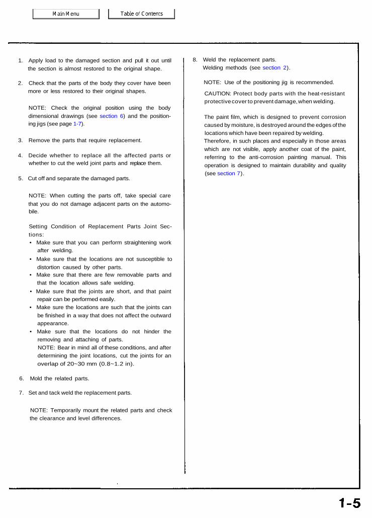
1. Apply load to the damaged section and pull it out untilthe section is almost restored to the original shape.
2. Check that the parts of the body they cover have beenmore or less restored to their original shapes.
NOTE: Check the original position using the bodydimensional drawings (see section 6) and the position-ing jigs (see page 1-7).
3. Remove the parts that require replacement.
4. Decide whether to replace all the affected parts orwhether to cut the weld joint parts and replace them.
5. Cut off and separate the damaged parts.
NOTE: When cutting the parts off, take special carethat you do not damage adjacent parts on the automo-bile.
Setting Condition of Replacement Parts Joint Sec-tions:• Make sure that you can perform straightening work
after welding.• Make sure that the locations are not susceptible to
distortion caused by other parts.• Make sure that there are few removable parts and
that the location allows safe welding.• Make sure that the joints are short, and that paint
repair can be performed easily.• Make sure the locations are such that the joints can
be finished in a way that does not affect the outwardappearance.
• Make sure that the locations do not hinder theremoving and attaching of parts.NOTE: Bear in mind all of these conditions, and afterdetermining the joint locations, cut the joints for anoverlap of 20~30 mm (0.8~1.2 in).
6. Mold the related parts.
7. Set and tack weld the replacement parts.
NOTE: Temporarily mount the related parts and checkthe clearance and level differences.
8. Weld the replacement parts.Welding methods (see section 2).
NOTE: Use of the positioning jig is recommended.
CAUTION: Protect body parts with the heat-resistantprotective cover to prevent damage, when welding.
The paint film, which is designed to prevent corrosioncaused by moisture, is destroyed around the edges of thelocations which have been repaired by welding.Therefore, in such places and especially in those areaswhich are not visible, apply another coat of the paint,referring to the anti-corrosion painting manual. Thisoperation is designed to maintain durability and quality(see section 7).

Preparation of WorkMeasurement (Excluding small damage)
POINTER A
When measuring body dimensions, use a universal tram gauge.
Whenever possible, make judgements and conclusions based on measurement. Measure the wheel alignment (see page 1-2) so as toprevent any future trouble like unsymmetrical wear of the tires or catching of the steering wheel.
If there are any deviations, use a tram tracking gauge and measure parts of the body.
If there is any twisting to the body, measure using a frame centering gauge.
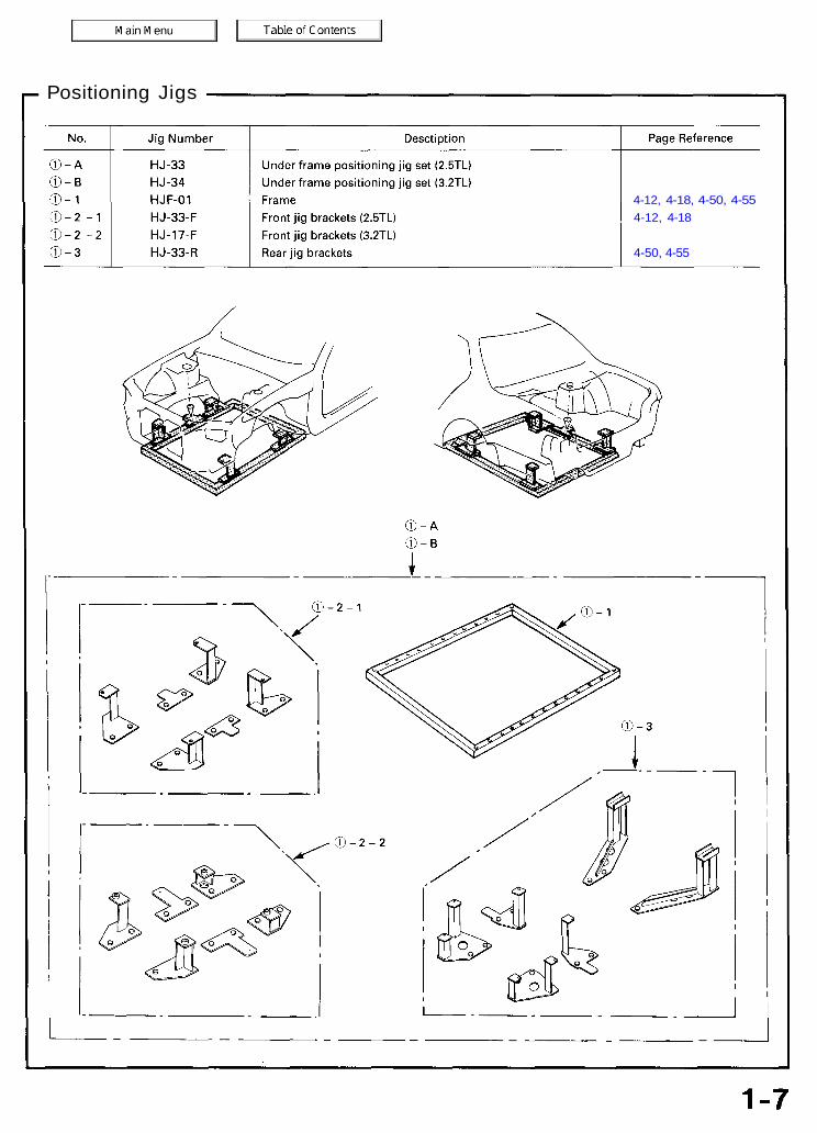
Positioning Jigs
4-12, 4-18, 4-50, 4-554-12, 4-18
4-50, 4-55
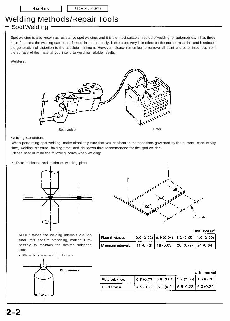
Welding Methods/Repair ToolsSpot WeldingSpot welding is also known as resistance spot welding, and it is the most suitable method of welding for automobiles. It has threemain features: the welding can be performed instantaneously, it exercises very little effect on the mother material, and it reducesthe generation of distortion to the absolute minimum. However, please remember to remove all paint and other impurities fromthe surface of the material you intend to weld for reliable results.
Welders:
Spot welder Timer
Welding Conditions:When performing spot welding, make absolutely sure that you conform to the conditions governed by the current, conductivitytime, welding pressure, holding time, and shutdown time recommended for the spot welder.Please bear in mind the following points when welding:
• Plate thickness and minimum welding pitch
NOTE: When the welding intervals are toosmall, this leads to branching, making it im-possible to maintain the desired solderingstate.• Plate thickness and tip diameter
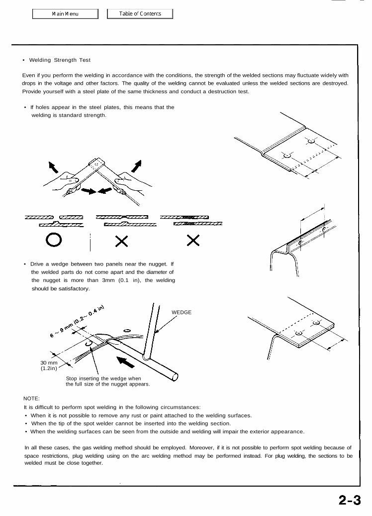
• Welding Strength Test
Even if you perform the welding in accordance with the conditions, the strength of the welded sections may fluctuate widely withdrops in the voltage and other factors. The quality of the welding cannot be evaluated unless the welded sections are destroyed.Provide yourself with a steel plate of the same thickness and conduct a destruction test.
• If holes appear in the steel plates, this means that thewelding is standard strength.
• Drive a wedge between two panels near the nugget. Ifthe welded parts do not come apart and the diameter ofthe nugget is more than 3mm (0.1 in), the weldingshould be satisfactory.
30 mm(1.2in)
WEDGE
Stop inserting the wedge whenthe full size of the nugget appears.
NOTE:It is difficult to perform spot welding in the following circumstances:• When it is not possible to remove any rust or paint attached to the welding surfaces.• When the tip of the spot welder cannot be inserted into the welding section.• When the welding surfaces can be seen from the outside and welding will impair the exterior appearance.
In all these cases, the gas welding method should be employed. Moreover, if it is not possible to perform spot welding because ofspace restrictions, plug welding using on the arc welding method may be performed instead. For plug welding, the sections to bewelded must be close together.

Welding Methods/Repair ToolsGas Welding
Gas welding is indispensable for body repair because of the broad range of its applications for joining the body panels, cutting thematerials that construct the body, and applying heat to reform panels, and also because it is easy to get hold of the tools.However, this method requires experience.
Welders:Gas regulator
Gas regulator
Welder
Cutter
Oxygen/Acetylene tanks
Welding Methods:
Butt welding Fillet welding or soldering
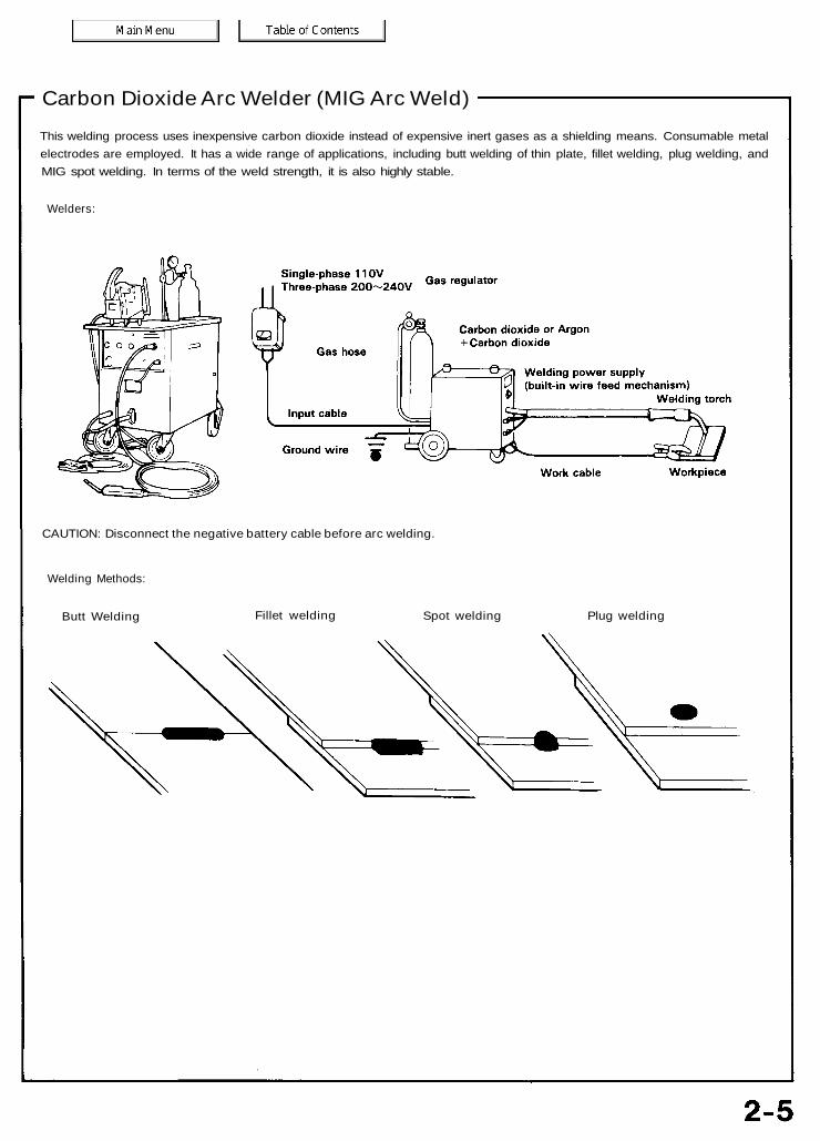
Carbon Dioxide Arc Welder (MIG Arc Weld)This welding process uses inexpensive carbon dioxide instead of expensive inert gases as a shielding means. Consumable metalelectrodes are employed. It has a wide range of applications, including butt welding of thin plate, fillet welding, plug welding, andMIG spot welding. In terms of the weld strength, it is also highly stable.
Welders:
CAUTION: Disconnect the negative battery cable before arc welding.
Welding Methods:
Butt Welding Fillet welding Spot welding Plug welding
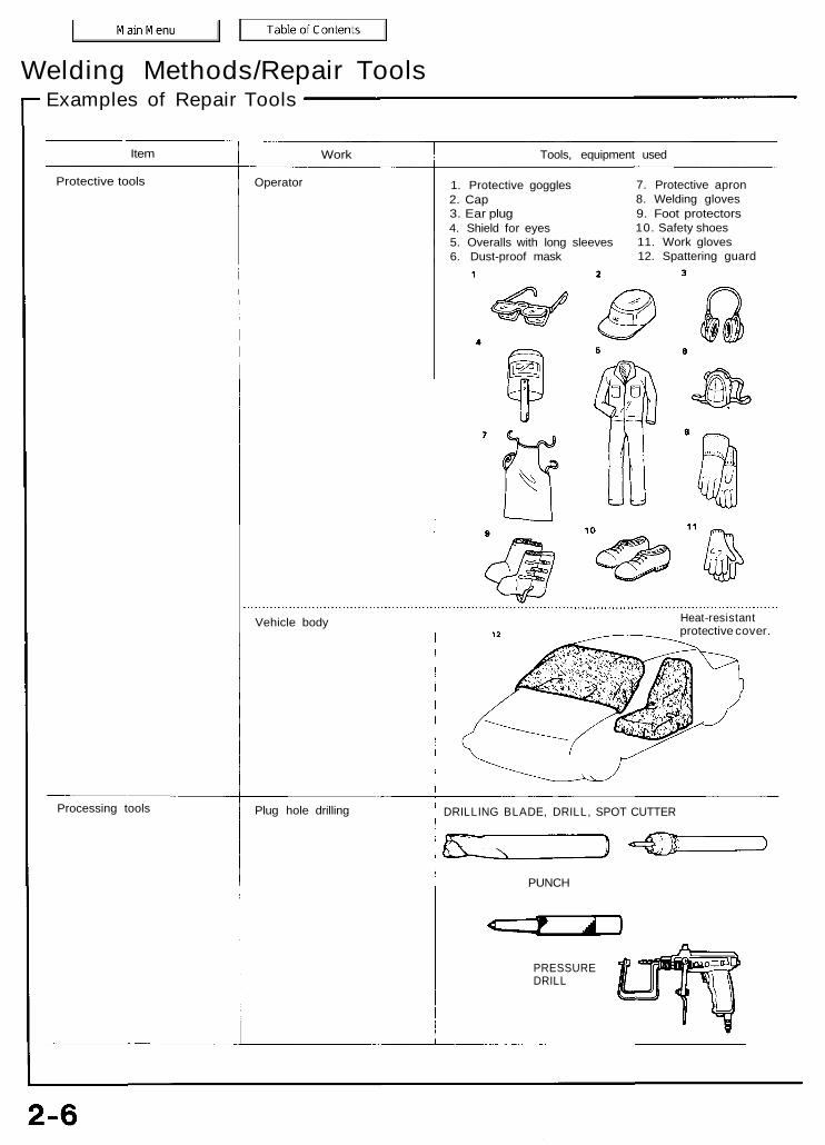
Welding Methods/Repair ToolsExamples of Repair Tools
Item Work Tools, equipment used
Protective tools Operator
Vehicle body
1. Protective goggles2. Cap3. Ear plug4. Shield for eyes5. Overalls with long sleeves6. Dust-proof mask
7. Protective apron8. Welding gloves9. Foot protectors10. Safety shoes11. Work gloves12. Spattering guard
Heat-resistantprotective cover.
Processing tools Plug hole drilling
PUNCH
PRESSUREDRILL
DRILLING BLADE, DRILL, SPOT CUTTER
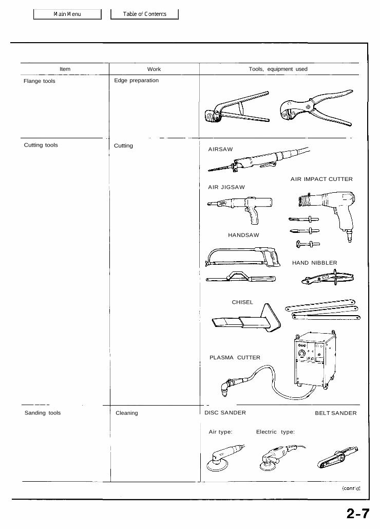
Item Work Tools, equipment used
Flange tools Edge preparation
Cutting tools Cutting AIRSAW
AIR IMPACT CUTTERAIR JIGSAW
HANDSAW
CHISEL
HAND NIBBLER
PLASMA CUTTER
Sanding tools Cleaning DISC SANDER
Air type: Electric type:
BELT SANDER
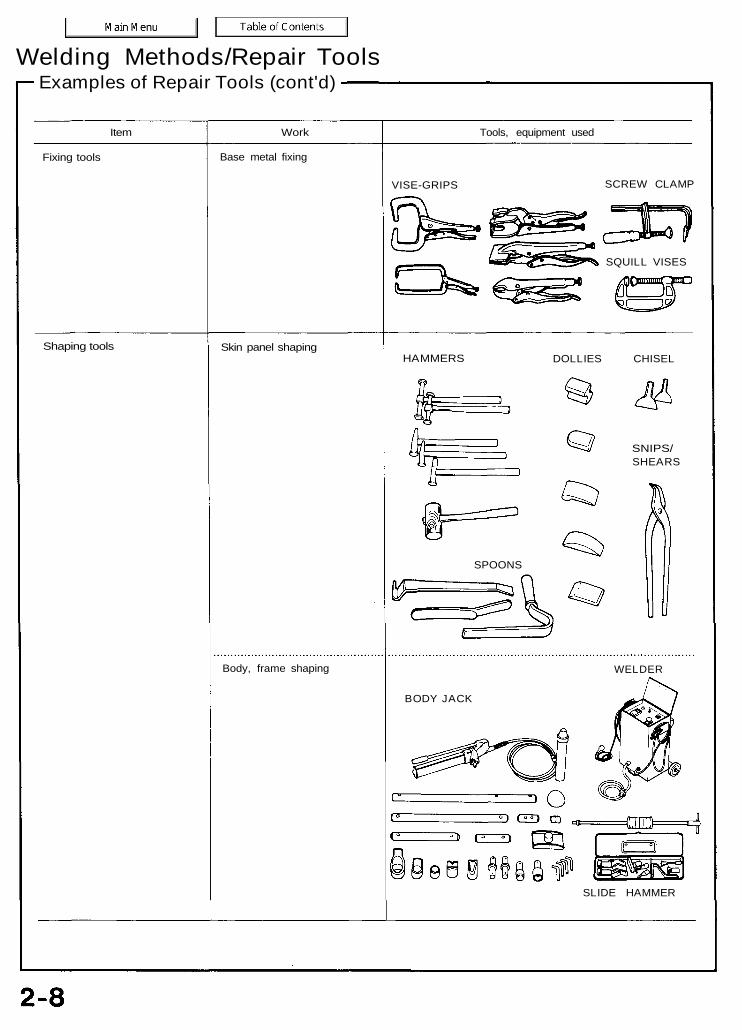
Welding Methods/Repair ToolsExamples of Repair Tools (cont'd)
Item Work Tools, equipment used
Fixing tools Base metal fixing
VISE-GRIPS SCREW CLAMP
Shaping tools Skin panel shaping
Body, frame shaping
HAMMERS DOLLIES CHISEL
SNIPS/SHEARS
SPOONS
WELDER
BODY JACK
SLIDE HAMMER
SQUILL VISES

General InformationZinc-plated Steel Plate Repair
The zinc-plated steel plate used in some panels of the Acura 2.5TL/3.2TL requires different repair techniques than ordinary steel plate.Refer to "Body Construction" (see page 4-2) for the location of the zinc-plated panels.
ZINC PLATING (5~6 microns)
Steel plate
1. Before spot welding the zinc-plated steel plate, remove the paint from both sides of the flange to be welded. Apply sealer tothe flange after welding.
To prevent eye injury, wear goggles or safety glasses whenever sanding, cutting or grinding.NOTE: Seal the sanded surfaces thoroughly to prevent rust.
2. The electric continuity properties of zinc-plated steel plate is different from ordinary steel plate. When spot welding, increasethe current by 10-20%, or increase the resistance welding time.Increase the number of weld spots by 10-20% also.
NOTE: The MIG welding procedures for zinc-plated steel plate are the same as for ordinary steel plate.
To prevent eye injury and burns when welding, wear an approved welding helmet, gloves and safetyshoes.
3. Before applying putty or body filler to the zinc-plated steel plate, sand the zinc plating thoroughly to promote adhesion andprevent blistering.
NOTE:• Use only epoxy-based putties and fillers on zinc-plated steel plate.• Follow the manufacturer's specification.
4. When performing paint work, apply caulking to the ground wiremounting position to mask the body.
SPECIALBOLT
GROUNDWIRE
CAULKING
GROUND WIREMOUNTINGHOLE

Avoid puttying as much as possible when repairing a new car. Use alternative methods as much as possible.
• Most paints contain substances that are harmful if inhaled or swallowed. Read the paint label before opening thecontainer. Spray paint only in a well ventilated area.
• Cover spilled paint with sand, or wipe it up at once.• Wear an approved respirator, gloves, eye protection and appropriate clothing when painting. Avoid contact with skin.• If paint gets in your mouth or on your skin, rinse or wash thoroughly with water. If paint gets in your eyes, flush with
water and get prompt medical attention.• Paint is flammable. Store it in a safe place, and keep it away from sparks, flames or cigarettes.
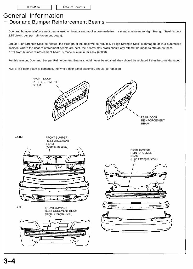
General InformationDoor and Bumper Reinforcement Beams
Door and bumper reinforcement beams used on Honda automobiles are made from a metal equivalent to High Strength Steel (except2.5TLfront bumper reinforcement beam).
Should High Strength Steel be heated, the strength of the steel will be reduced. If High Strength Steel is damaged, as in a automobileaccident where the door reinforcement beams are bent, the beams may crack should any attempt be made to straighten them.2.5TL front bumper reinforcement beam is made of aluminum alloy (#6000).
For this reason, Door and Bumper Reinforcement Beams should never be repaired, they should be replaced if they become damaged.
NOTE: If a door beam is damaged, the whole door panel assembly should be replaced.
FRONT DOORREINFORCEMENTBEAM
REAR DOORREINFORCEMENTBEAM
2.5TL: FRONT BUMPERREINFORCEMENTBEAM(Aluminum alloy)
REAR BUMPERREINFORCEMENTBEAM(High Strength Steel)
vffMr/////////////////////^Wmmm/mmm//////^/),
3.2TL: FRONT BUMPERREINFORCEMENT BEAM(High Strength Steel)
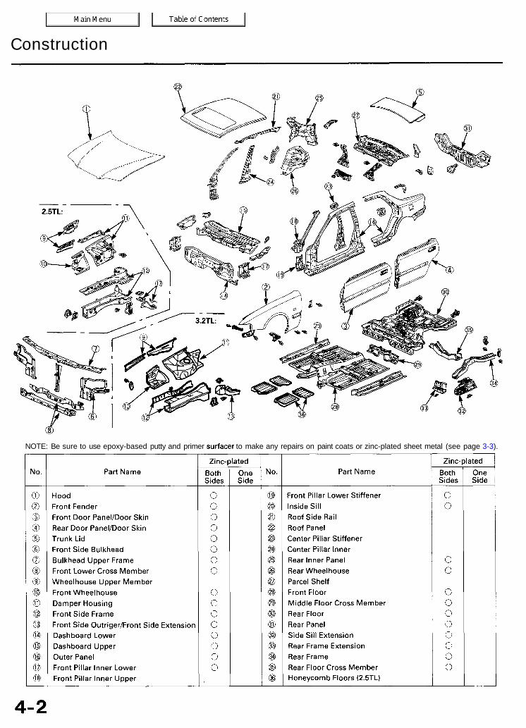
Construction
NOTE: Be sure to use epoxy-based putty and primer surfacer to make any repairs on paint coats or zinc-plated sheet metal (see page 3-3).
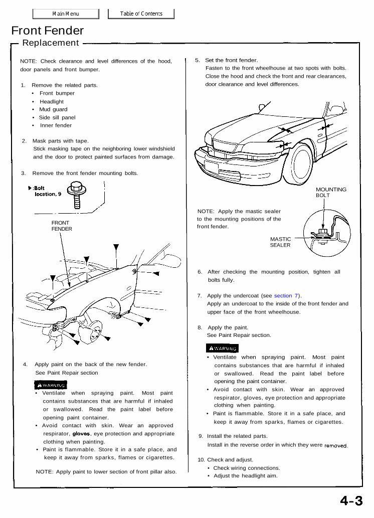
Front FenderReplacement
NOTE: Check clearance and level differences of the hood,door panels and front bumper.
1. Remove the related parts.• Front bumper• Headlight• Mud guard• Side sill panel• Inner fender
2. Mask parts with tape.Stick masking tape on the neighboring lower windshieldand the door to protect painted surfaces from damage.
3. Remove the front fender mounting bolts.
FRONTFENDER
4. Apply paint on the back of the new fender.See Paint Repair section
• Ventilate when spraying paint. Most paintcontains substances that are harmful if inhaledor swallowed. Read the paint label beforeopening paint container.
• Avoid contact with skin. Wear an approvedrespirator, gloves, eye protection and appropriateclothing when painting.
• Paint is flammable. Store it in a safe place, andkeep it away from sparks, flames or cigarettes.
NOTE: Apply paint to lower section of front pillar also.
5. Set the front fender.Fasten to the front wheelhouse at two spots with bolts.Close the hood and check the front and rear clearances,door clearance and level differences.
MOUNTINGBOLT
NOTE: Apply the mastic sealerto the mounting positions of thefront fender.
MASTICSEALER
6. After checking the mounting position, tighten allbolts fully.
7. Apply the undercoat (see section 7).Apply an undercoat to the inside of the front fender andupper face of the front wheelhouse.
8. Apply the paint.See Paint Repair section.
• Ventilate when spraying paint. Most paintcontains substances that are harmful if inhaledor swallowed. Read the paint label beforeopening the paint container.
• Avoid contact with skin. Wear an approvedrespirator, gloves, eye protection and appropriateclothing when painting.
• Paint is flammable. Store it in a safe place, andkeep it away from sparks, flames or cigarettes.
9. Install the related parts.Install in the reverse order in which they were removed.
10. Check and adjust.• Check wiring connections.• Adjust the headlight aim.

Front BulkheadDescription
The front bulkhead is joined to the front wheelhouse and front side frame. It forms the base for the headlights and other parts andmaintains the rigidity of the front section of the body. Pay particular attention to twists and parallelism and check mounting ofrelated parts when welding.
Mass Production Body Welding Diagram
2.5TL: 3.2TL:
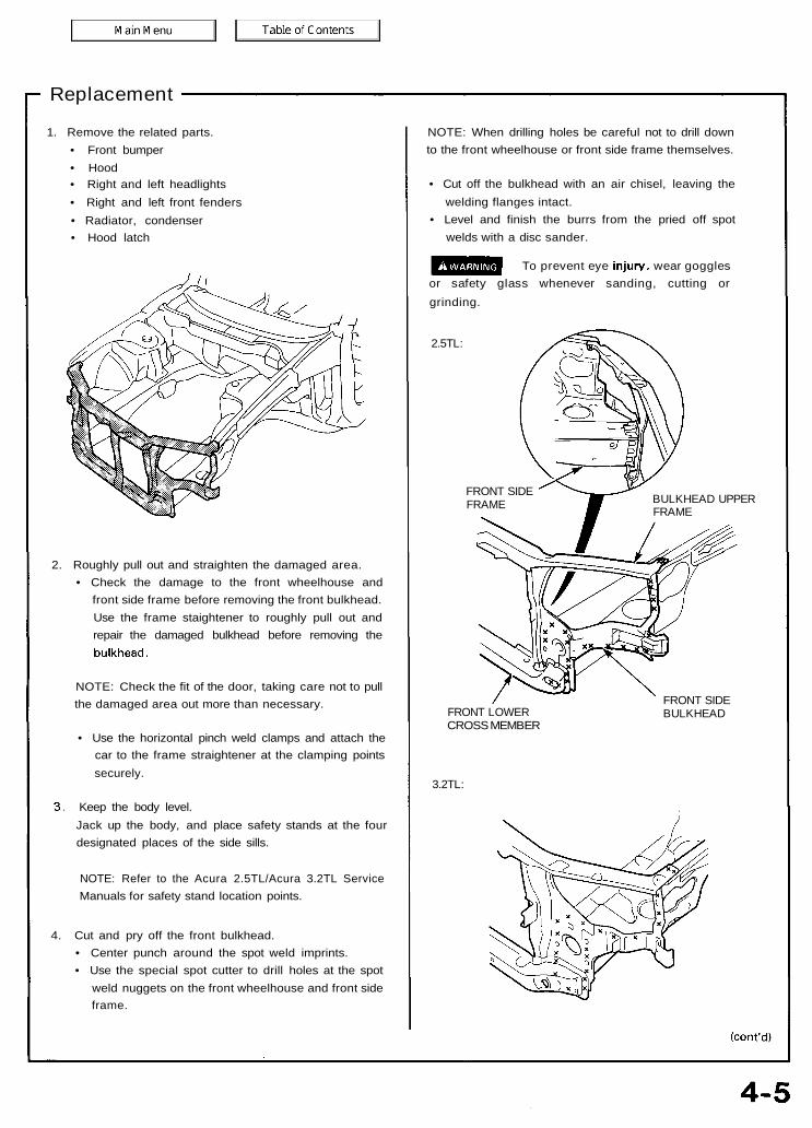
Replacement
1. Remove the related parts.• Front bumper• Hood• Right and left headlights• Right and left front fenders• Radiator, condenser• Hood latch
-1
2. Roughly pull out and straighten the damaged area.• Check the damage to the front wheelhouse and
front side frame before removing the front bulkhead.Use the frame staightener to roughly pull out andrepair the damaged bulkhead before removing thebulkhead.
NOTE: Check the fit of the door, taking care not to pullthe damaged area out more than necessary.
• Use the horizontal pinch weld clamps and attach thecar to the frame straightener at the clamping pointssecurely.
3. Keep the body level.Jack up the body, and place safety stands at the fourdesignated places of the side sills.
NOTE: Refer to the Acura 2.5TL/Acura 3.2TL ServiceManuals for safety stand location points.
4. Cut and pry off the front bulkhead.• Center punch around the spot weld imprints.• Use the special spot cutter to drill holes at the spot
weld nuggets on the front wheelhouse and front sideframe.
NOTE: When drilling holes be careful not to drill downto the front wheelhouse or front side frame themselves.
• Cut off the bulkhead with an air chisel, leaving thewelding flanges intact.
• Level and finish the burrs from the pried off spotwelds with a disc sander.
To prevent eye injury, wear gogglesor safety glass whenever sanding, cutting orgrinding.
2.5TL:
FRONT SIDEFRAME BULKHEAD UPPER
FRAME
FRONT LOWERCROSS MEMBER
FRONT SIDEBULKHEAD
3.2TL:
Front BulkheadReplacement (cont'd)
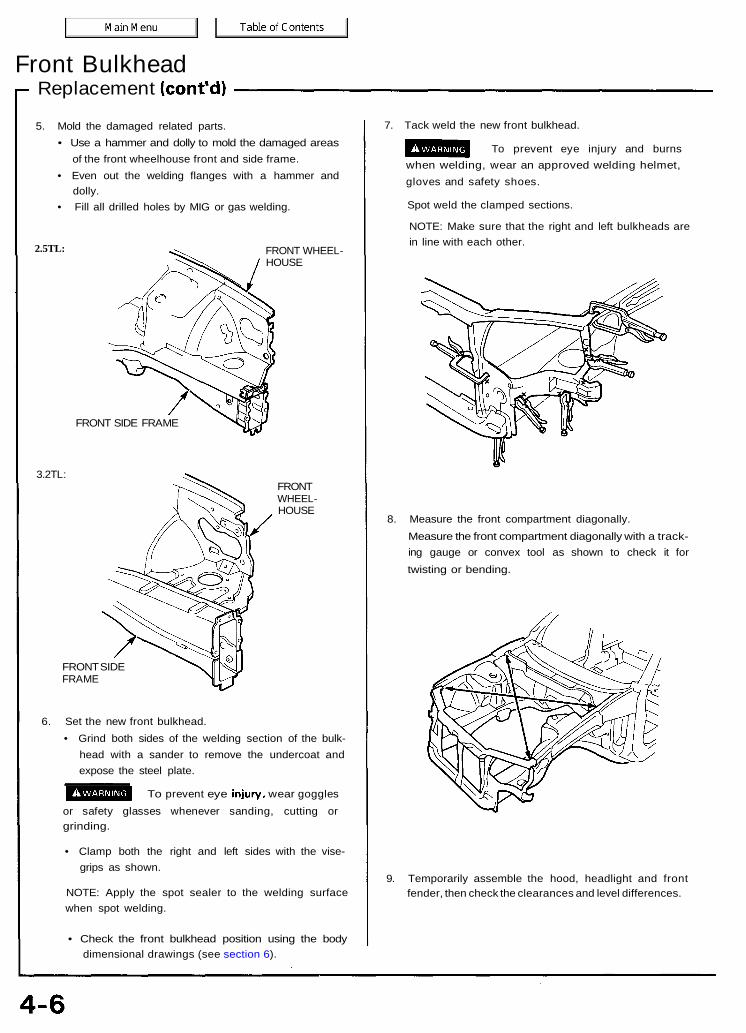
5. Mold the damaged related parts.• Use a hammer and dolly to mold the damaged areas
of the front wheelhouse front and side frame.• Even out the welding flanges with a hammer and
dolly.• Fill all drilled holes by MIG or gas welding.
2.5TL: FRONT WHEEL-HOUSE
FRONT SIDE FRAME
3.2TL:FRONTWHEEL-HOUSE
FRONT SIDEFRAME
6. Set the new front bulkhead.• Grind both sides of the welding section of the bulk-
head with a sander to remove the undercoat andexpose the steel plate.
U^̂ JQQ To prevent eye injury, wear gogglesor safety glasses whenever sanding, cutting orgrinding.
• Clamp both the right and left sides with the vise-grips as shown.
NOTE: Apply the spot sealer to the welding surfacewhen spot welding.
• Check the front bulkhead position using the bodydimensional drawings (see section 6).
7. Tack weld the new front bulkhead.
To prevent eye injury and burnswhen welding, wear an approved welding helmet,gloves and safety shoes.
Spot weld the clamped sections.
NOTE: Make sure that the right and left bulkheads arein line with each other.
8. Measure the front compartment diagonally.Measure the front compartment diagonally with a track-ing gauge or convex tool as shown to check it fortwisting or bending.
9. Temporarily assemble the hood, headlight and frontfender, then check the clearances and level differences.
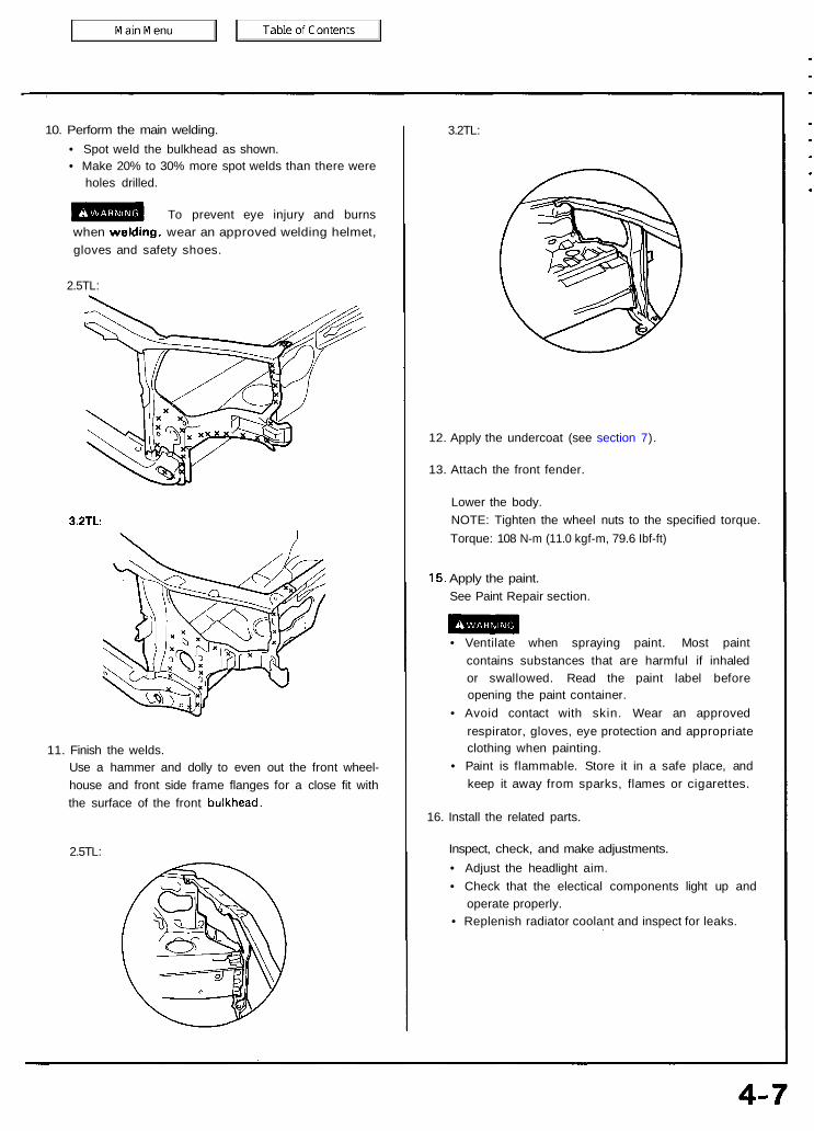
10. Perform the main welding.• Spot weld the bulkhead as shown.• Make 20% to 30% more spot welds than there were
holes drilled.
To prevent eye injury and burnswhen welding, wear an approved welding helmet,gloves and safety shoes.
2.5TL:
3.2TL
11. Finish the welds.Use a hammer and dolly to even out the front wheel-house and front side frame flanges for a close fit withthe surface of the front bulkhead.
2.5TL:
3.2TL:
12. Apply the undercoat (see section 7).
13. Attach the front fender.
14. Lower the body.NOTE: Tighten the wheel nuts to the specified torque.Torque: 108 N-m (11.0 kgf-m, 79.6 Ibf-ft)
15. Apply the paint.See Paint Repair section.
• Ventilate when spraying paint. Most paintcontains substances that are harmful if inhaledor swallowed. Read the paint label beforeopening the paint container.
• Avoid contact with skin. Wear an approvedrespirator, gloves, eye protection and appropriateclothing when painting.
• Paint is flammable. Store it in a safe place, andkeep it away from sparks, flames or cigarettes.
16. Install the related parts.
17. Inspect, check, and make adjustments.• Adjust the headlight aim.• Check that the electical components light up and
operate properly.• Replenish radiator coolant and inspect for leaks.

Front Wheelhouse/Damper HousingDescription
The front wheelhouse component is constructed as a unit with the front damper housing. Therefore, replacement of thecomponent affects the front wheel alignment. When assembling it, either use a positioning jig or follow dimensions on theframe repair chart for positioning. Weld carefully.

Mass Production Body Welding DiagramFront Wheelhouse/Damper Housing
2.5TL:
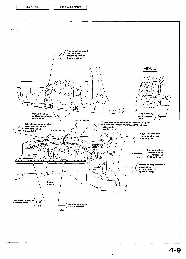
3.2TL:
Front Wheelhouse/Damper HousingReplacement
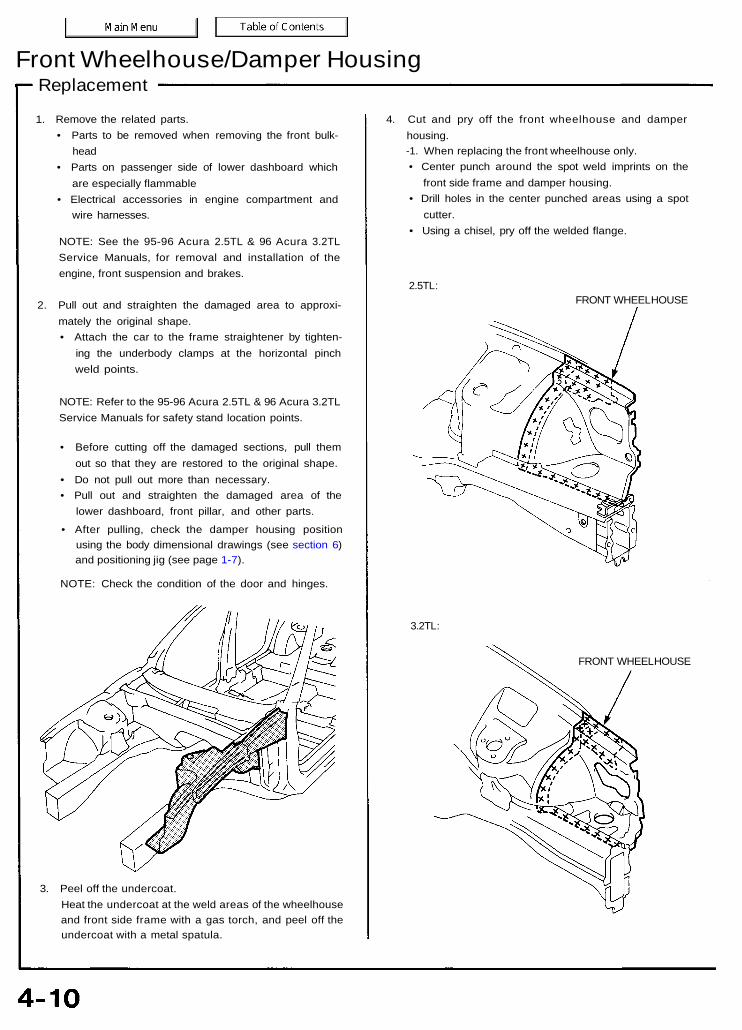
1. Remove the related parts.• Parts to be removed when removing the front bulk-
head• Parts on passenger side of lower dashboard which
are especially flammable• Electrical accessories in engine compartment and
wire harnesses.
NOTE: See the 95-96 Acura 2.5TL & 96 Acura 3.2TLService Manuals, for removal and installation of theengine, front suspension and brakes.
2. Pull out and straighten the damaged area to approxi-mately the original shape.• Attach the car to the frame straightener by tighten-
ing the underbody clamps at the horizontal pinchweld points.
NOTE: Refer to the 95-96 Acura 2.5TL & 96 Acura 3.2TLService Manuals for safety stand location points.
• Before cutting off the damaged sections, pull themout so that they are restored to the original shape.
• Do not pull out more than necessary.• Pull out and straighten the damaged area of the
lower dashboard, front pillar, and other parts.
• After pulling, check the damper housing positionusing the body dimensional drawings (see section 6)and positioning jig (see page 1-7).
NOTE: Check the condition of the door and hinges.
3. Peel off the undercoat.Heat the undercoat at the weld areas of the wheelhouseand front side frame with a gas torch, and peel off theundercoat with a metal spatula.
4. Cut and pry off the front wheelhouse and damperhousing.-1. When replacing the front wheelhouse only.• Center punch around the spot weld imprints on the
front side frame and damper housing.• Drill holes in the center punched areas using a spot
cutter.• Using a chisel, pry off the welded flange.
2.5TL:FRONT WHEELHOUSE
3.2TL:
FRONT WHEELHOUSE

-2. Replace the damper housing with the frontwheelhouse.
• Remove the wheelhouse upper rear member.• Remove the MIG weld flange with a disc sander.
To prevent eye injury, wear goggles orsafety glasses whenever sanding, cutting or grinding.
• Using a chisel, pry off the welded flange form thefront pillar and damper housing.
NOTE: Remove the wheelhouse upper rear membercarefully so they can be reused.
2.5TL:
3.2TL:
WHEELHOUSE UPPERREAR MEMBER
WHEELHOUSE UPPERREAR MEMBER
2.5TL:
DASHBOARDUPPER SIDEMEMBER
3.2TL:
DAMPERHOUSING
FRONT SIDE FRAME
DASHBOARD UPPER SIDE MEMBER
FRONT PILLARINNER LOWER

Front wheelhouse/Damper housingReplacement (cont'd)
5. Mold the related parts.• Level and finish the burrs left on the welding
surfaces with a sander.• Fill all drilled holes by MIG or gas welding.
Use a hammer and dolly to even out the welded areas ofthe lower dashboard, front side frame and dashboardupper side member.
2.5TL: 3.2TL:
WHEELHOUSE UPPERMEMBER DIAGONAL
WHEELHOUSEUPPEREXTENSION
FRONT SIDE FRAME
DASHBOARD UPPERSIDE MEMBER
DASHBOARD LOWER
DAMPER STIFFENER
FRONT SIDE FRAME
6. Set the new front wheelhouse and damper housing.
• Apply body paint to both sides of the new frontwheelhouse and damper housing.
• See Paint Repair section.
• Ventilate when spraying paint. Most paintcontains substances that are harmful if inhaledor swallowed. Read the paint label beforeopening the paint container.
• Avoid contact with skin. Wear an approvedrespirator, gloves, eye protection and appropriateclothing when painting.
• Paint is flammble. Store it in a safe place, andkeep it away from sparks, flames or cigarettes.
• Remove the undercoat from both sides of the weld-ing section and expose the steel plate using a discsander.
To prevent eye injury, wear gogglesor safety glasses whenever sanding, cutting orgrinding.
• Clamp to the front side frame with vise-grips andsquill vises.
NOTE: Apply the spot sealer to the welding surfacewhen spot welding.• Clamp the front bulkhead with vise-grips.• Measure the front compartment diagonally.
NOTE: Use of a positioning jig is recommended (seepage 1-7).
POSITIONING JIG
• Spot weld several points in the clamped sections, andtemporarily attach the front wheelhouse and damperhousing.
To prevent eye injury and burnswhen welding, wear an approved welding helmet,gloves and safety shoes.
7. Check the dimensions, temporarily install the hood, frontfender and headlight, and check for differences in leveland clearance.
DAMPERHOUSING
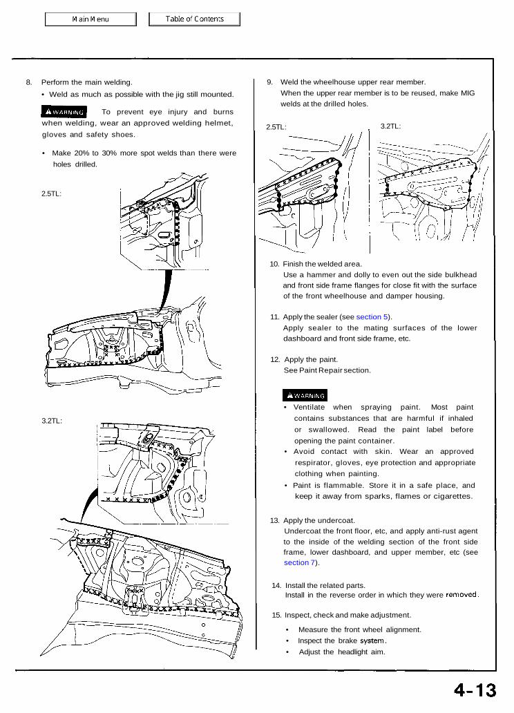
8. Perform the main welding.• Weld as much as possible with the jig still mounted.
To prevent eye injury and burnswhen welding, wear an approved welding helmet,gloves and safety shoes.
• Make 20% to 30% more spot welds than there wereholes drilled.
2.5TL:
3.2TL:
9. Weld the wheelhouse upper rear member.When the upper rear member is to be reused, make MIGwelds at the drilled holes.
2.5TL: 3.2TL:
10. Finish the welded area.Use a hammer and dolly to even out the side bulkheadand front side frame flanges for close fit with the surfaceof the front wheelhouse and damper housing.
11. Apply the sealer (see section 5).Apply sealer to the mating surfaces of the lowerdashboard and front side frame, etc.
12. Apply the paint.See Paint Repair section.
• Ventilate when spraying paint. Most paintcontains substances that are harmful if inhaledor swallowed. Read the paint label beforeopening the paint container.
• Avoid contact with skin. Wear an approvedrespirator, gloves, eye protection and appropriateclothing when painting.
• Paint is flammable. Store it in a safe place, andkeep it away from sparks, flames or cigarettes.
13. Apply the undercoat.Undercoat the front floor, etc, and apply anti-rust agentto the inside of the welding section of the front sideframe, lower dashboard, and upper member, etc (seesection 7).
14. Install the related parts.Install in the reverse order in which they were removed.
15. Inspect, check and make adjustment.
• Measure the front wheel alignment.• Inspect the brake system.• Adjust the headlight aim.
DescriptionFront Side Frame
The front side frame acts as a base for the front suspension and is highly important in maintaining the rigidity of the front section.Pay careful attention to the position and dimensions of the weld joints and weld carefully.

Mass Production Body Welding Diagram
2.5TL:
NOTE: Replace the front side frame and front side outrigger as an assembly.
Front Side Frame
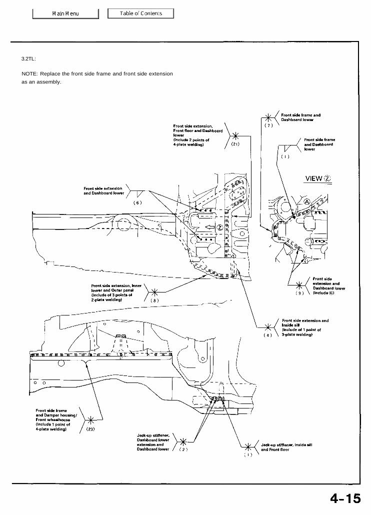
3.2TL:
NOTE: Replace the front side frame and front side extensionas an assembly.

Front Side FrameReplacement
1. Remove the related parts.• Front suspension related parts• Brake hoses and pipes• Engine compartment electrical components• Fittings in passenger compartment, etc.• Steering gearbox.
2. Remove the sub-frame.
NOTE: With the front bulkhead removed.
3. Roughly pull out and straighten the damaged area.• Attach the car to the frame straightener by tighten-
ing the underbody clamps located at the horizontalpinch welds.
NOTE: Refer to the 95-96 Acura 2.5TL & 96 Acura 3.2TLService Manuals for safety stand location points.
• Before cutting off the damaged sections, pull themout so that they are restored to the original shape.
• Cutting off the front side frame before roughlypulling out the damage makes repair of the relatedfront floor, lower dashboard, and other related partsdifficult.
4. Peel off the undercoat.Heat the undercoat at the weld areas of the lowerdashboard, front floor and side sill with a gas torch andpeel off the undercoat with a metal spatula.
CAUTION: Be careful not to burn the fittings insidethe passenger compartment when heating.
5. Remove the front side frame.NOTE: It's not necessary to separate the front wheel-house from the front side frame if the wheelhouse/damper housing is to be replaced also.
• Center punch around the spot weld imprints on thewheelhouse, damper housing, lower dashboard, frontfloor and floor frame.
• Using a spot cutter, drill holes in the spot weldedareas.
• Peel off the welding flange using the chisel.

Remove the burrs from the drilled sections with adisc sander.
To prevent eye injury, wear gogglesor safety glasses whenever sanding, cutting orgrinding.
NOTE: When drilling holes and be careful not todrill down to the inside sill.
2.5TL:
• Center punch around the spot weld imprints on thefront side frame and front side outrigger from insidethe passenger compartment.
• Drill holes in the spot welded area with a 5 mm (0.2 in)drill.
NOTE: Drill holes completely through the parts since thereplacement front side frame, front side outrigger and jack-upstiffener will be welded by MIG welding.
• Remove the MIG welds of the front side frame-and-lowerdashboard with a disc sander.

Front Side FrameReplacement (cont'd)
6. Mold the related parts.
• Reshape the front wheelhouse and damper housinglower dashboard-to-front floor joint using a hammerand dolly.
• Fill all drilled holes by MIG or gas welding.
7. Set the new front side frame.• Remove the undercoat from the both sides of the
welding section, and expose the steel plate using adisc sander.
To prevent eye injury, wear gogglesor safety glasses whenever sanding, cutting orgrinding.
NOTE: Apply the spot sealer to the welding surfacewhen spot welding.
• Tighten the front side frame against the front floorand side sill using vise-grips or pliers.
• Place a jack under the front side frame end andsupport it, and measure the positions for temporaryattachment.
NOTE: Use of a positioning jig is recommended (seepage 1-7).
• Clamp the front bulkhead and front wheelhouse/damper housing with squill vises and vise-grips.
• Measure the front compartment diagonally.
• Spot weld several points in the clamped sections,and temporarily attach the front side frame.
To prevent eye injury and burnswhen welding, wear an approved welding helmet,gloves and safety shoes.
• Check the body dimensions (see section 6).

8. Perform the main welding.• Make 20% to 30% more spot welds than there were
holes drilled.• Weld as much as possible with the jig still mounted.
To prevent eye injury and burnswhen welding, wear an approved welding helmet,gloves and safety shoes.
• Weld the front side frame, wheelhouse, damperhousing and bulkhead.
• and make 5 mm (0.2 in) holes in the MIG weldholes with the outrigger, and plug weld the inside sillwith a MIG welder.
2.5TL:
3.2TL:
• From the passenger compartment side, plug weldthe holed areas of the lower dashboard and frontfloor with a MIG welder.
2.5TL:
Front Side FrameReplacement (cont'd)
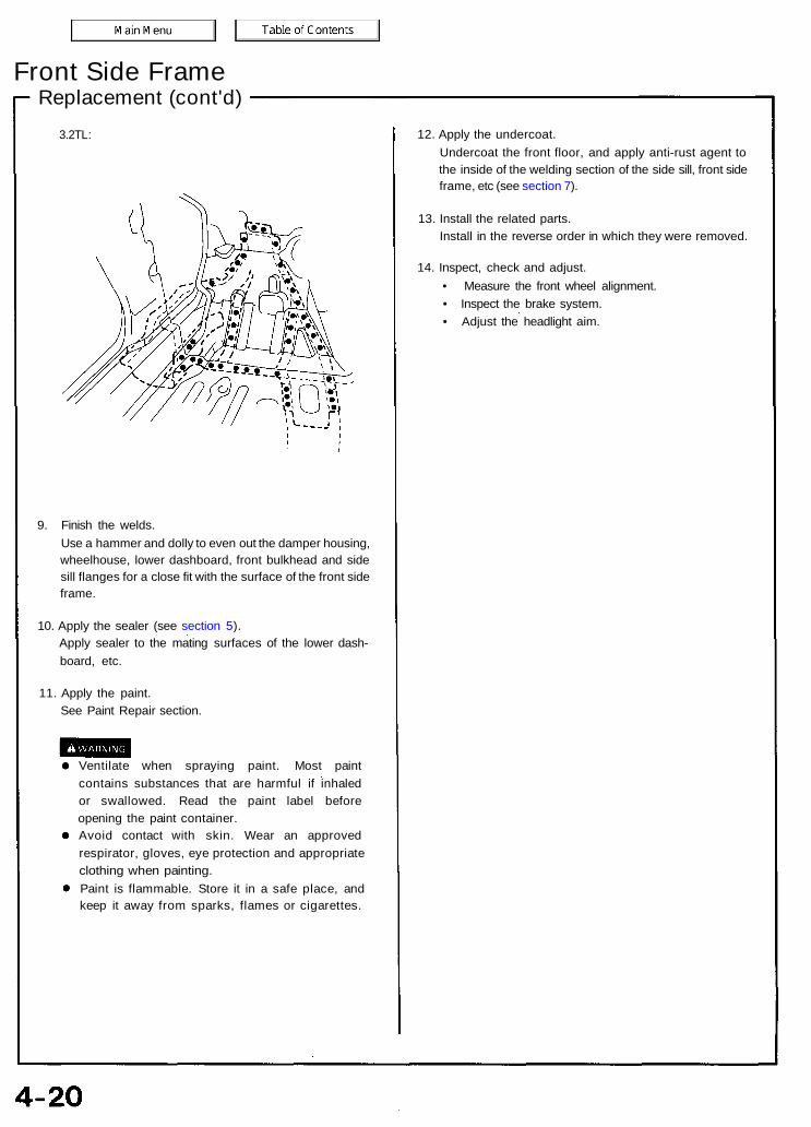
3.2TL:
9. Finish the welds.Use a hammer and dolly to even out the damper housing,wheelhouse, lower dashboard, front bulkhead and sidesill flanges for a close fit with the surface of the front sideframe.
10. Apply the sealer (see section 5).Apply sealer to the mating surfaces of the lower dash-board, etc.
11. Apply the paint.See Paint Repair section.
Ventilate when spraying paint. Most paintcontains substances that are harmful if inhaledor swallowed. Read the paint label beforeopening the paint container.Avoid contact with skin. Wear an approvedrespirator, gloves, eye protection and appropriateclothing when painting.Paint is flammable. Store it in a safe place, andkeep it away from sparks, flames or cigarettes.
12. Apply the undercoat.Undercoat the front floor, and apply anti-rust agent tothe inside of the welding section of the side sill, front sideframe, etc (see section 7).
13. Install the related parts.Install in the reverse order in which they were removed.
14. Inspect, check and adjust.• Measure the front wheel alignment.• Inspect the brake system.• Adjust the headlight aim.
DescriptionFront Side Outrigger/Front Side Extension
The front side outriggers connect the front side frames to the body and are vital to the rigidity of the entire body frame. Payparticular attention when welding the front side outriggers from beneath the front floor and side sill.
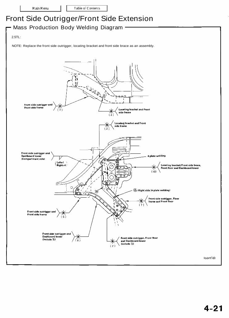
Front Side Outrigger/Front Side ExtensionMass Production Body Welding Diagram
2.5TL:
NOTE: Replace the front side outrigger, locating bracket and front side brace as an assembly.

Front side Outrigger/Front Side ExtensionMass Production Body Welding Diagram (cont'd)
3.2TL:
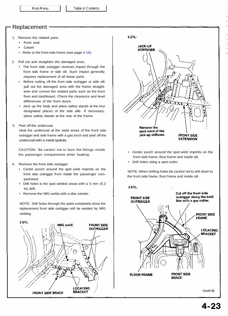
Replacement
1. Remove the related parts.• Front seat• Carpet• Refer to the front side frame (see page 4-16).
2. Pull out and straighten the damaged area.• The front side outrigger receives impact through the
front side frame or side sill. Such impact generallyrequires replacement of all these parts.
• Before cutting off the front side outrigger or side sill,pull out the damaged area with the frame straight-ener and correct the related parts such as the frontfloor and dashboard. Check the clearance and leveldifferences of the front doors.
• Jack up the body and place safety stands at the fourdesignated places of the side sills. If necessary,place safety stands at the rear of the frame.
3. Peel off the undercoat.Heat the undercoat at the weld areas of the front sideoutrigger and side frame with a gas torch and peel off theundercoat with a metal spatula.
CAUTION: Be careful not to burn the fittings insidethe passenger compartment when heating.
4. Remove the front side outrigger.• Center punch around the spot weld imprints on the
front side outrigger from inside the passenger com-partment.
• Drill holes is the spot welded areas with a 5 mm (0.2in) drill.
• Remove the MIG welds with a disc sander.
NOTE: Drill holes through the parts completely since thereplacement front side outrigger will be welded by MIGwelding.
• Center punch around the spot weld imprints on thefront side frame, floor frame and inside sill.
• Drill holes using a spot cutter.
NOTE: When drilling holes be careful not to drill down tothe front side frame, floor frame and inside sill.

Front Side Outrigger/Front Side ExtensionReplacement (cont'd)
3.2TL:
FRONT SIDEFRAME
FRONT SIDEEXTENSION
FLOOR FRAME
Level off and finish the burrs of the pried off spotwelds with a disc sander.
To prevent eye injury, wear gogglesor safety glasses whenever sanding, cutting orgrinding.
5. Mold the related parts.Reshape the lower dashboard, front side frame, frontfloor, inside sill and side sill inner joint using a hammerand dolly.
2.5TL:
Remove the remains ofthe front side outrigger.
FRONT SIDE FRAME
6. Set the new front side outrigger.• Remove the undercoat from both sides of the areas
to be spot welded with a sander to expose the steelplate.
• Clamp the weld flanges with the side sill using thevise-grip pliers. Set the front side outrigger on theside frame using a jack.
• Drill 3 mm (0.12 in) holes, and screw 5 mm self-tapping screws into the drilled holes at the areaswhere the front side outrigger does not fit closely.
• Even out the welded flange and damaged area witha hammer and dolly.
7. Perform the main welding.
To prevent eye injury and burnswhen welding, wear an approved welding helmet,gloves and safety shoes.
• From the passenger compartment side, weld theholes in the lower dashboard, front floor and floorframe with a MIG welder.
• Weld the front side frame and front side outriggerusing MIG welds.
2.5TL:
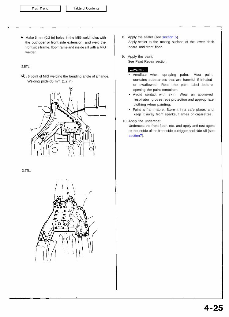
Make 5 mm (0.2 in) holes in the MIG weld holes withthe outrigger or front side extension, and weld thefront side frame, floor frame and inside sill with a MIGwelder.
2.5TL:
6 point of MIG welding the bending angle of a flange.Welding pitch=30 mm (1.2 in)
3.2TL:
8. Apply the sealer (see section 5).Apply sealer to the mating surface of the lower dash-board and front floor.
9. Apply the paint.See Paint Repair section.
• Ventilate when spraying paint. Most paintcontains substances that are harmful if inhaledor swallowed. Read the paint label beforeopening the paint container.
• Avoid contact with skin. Wear an approvedrespirator, gloves, eye protection and appropriateclothing when painting.
• Paint is flammable. Store it in a safe place, andkeep it away from sparks, flames or cigarettes.
10. Apply the undercoat.Undercoat the front floor, etc, and apply anti-rust agentto the inside of the front side outrigger and side sill (seesection 7).
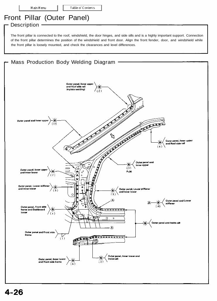
Front Pillar (Outer Panel)Description
The front pillar is connected to the roof, windshield, the door hinges, and side sills and is a highly important support. Connectionof the front pillar determines the position of the windshield and front door. Align the front fender, door, and windshield whilethe front pillar is loosely mounted, and check the clearances and level differences.
Mass Production Body Welding Diagram

Replacement
1. Remove the related parts:• Hood• Front fender• Front door• Windshield• Front side trim• Door opening trim• Side cowl lining• Dashboard• Front pillar trim• Wire harness, etc.• Steering column• Steering hanger pipe
NOTE: Make sure that the right and left pillars areparallel with the windshield surface. Check the door forproper opening and closing.
2. Pull out and straighten the damaged area.• Pull out the damaged area with the frame straight-
ener before cutting off the front pillar extension andfront pillar.
NOTE: Pull out until the pillar is lined up with thesurface of the windshield.
• With the pillar pulled out, pull out and straighten therelated lower dashboard and floor section.
• After pulling, check the inner pillar position using thebody dimensional drawings (see section 6).
3. Remove the wheelhouse upper rear member.
WHEELHOUSEUPPER REAR MEMBER
4. Cut off the front pillar.• Cut off the front pillar along the bold line shown in
the figure to the right with a gas cutter.• Use a handsaw to cut the windshield and side sill
areas.
NOTE: Be careful not to cut the inner section.
• Center punch around the spot weld imprints.• Drill holes using a spot cutter.• Chisel off the weld flanges.• Finish the burrs at the drilled areas with a disc
sander.
To prevent eye injury, wear gogglesor safety glasses whenever sanding, cutting orgrinding.
OUTERPANEL
INNERUPPER
OUTER PANEL
Repair the front pillar lower stiffener if necessary.
FRONT INNER UPPERPILLAR
FRONT PILLAR LOWERSTIFFENER
UPPERSTIFFENER
INSIDE SILL
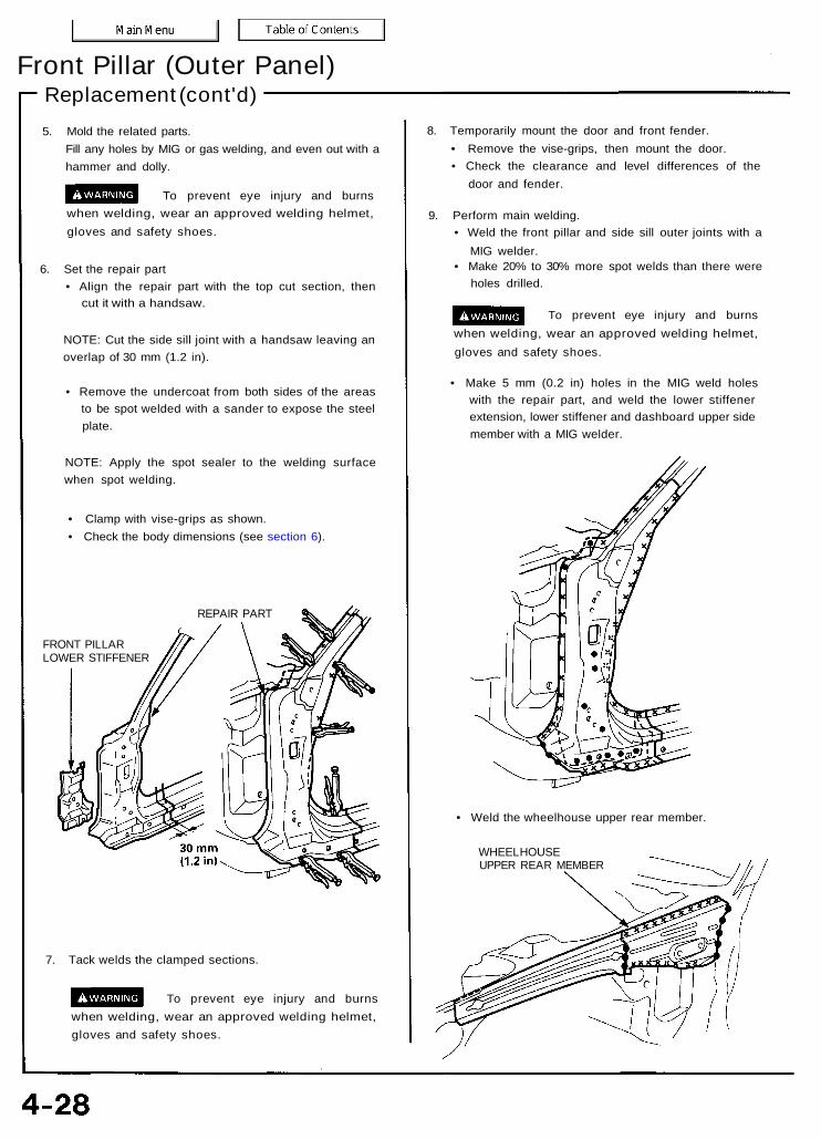
Front Pillar (Outer Panel)Replacement (cont'd)5. Mold the related parts.
Fill any holes by MIG or gas welding, and even out with ahammer and dolly.
To prevent eye injury and burnswhen welding, wear an approved welding helmet,gloves and safety shoes.
6. Set the repair part• Align the repair part with the top cut section, then
cut it with a handsaw.
NOTE: Cut the side sill joint with a handsaw leaving anoverlap of 30 mm (1.2 in).
• Remove the undercoat from both sides of the areasto be spot welded with a sander to expose the steelplate.
NOTE: Apply the spot sealer to the welding surfacewhen spot welding.
• Clamp with vise-grips as shown.• Check the body dimensions (see section 6).
REPAIR PART
FRONT PILLARLOWER STIFFENER
7. Tack welds the clamped sections.
To prevent eye injury and burnswhen welding, wear an approved welding helmet,gloves and safety shoes.
8. Temporarily mount the door and front fender.• Remove the vise-grips, then mount the door.• Check the clearance and level differences of the
door and fender.
9. Perform main welding.• Weld the front pillar and side sill outer joints with a
MIG welder.• Make 20% to 30% more spot welds than there were
holes drilled.
To prevent eye injury and burnswhen welding, wear an approved welding helmet,gloves and safety shoes.
• Make 5 mm (0.2 in) holes in the MIG weld holeswith the repair part, and weld the lower stiffenerextension, lower stiffener and dashboard upper sidemember with a MIG welder.
• Weld the wheelhouse upper rear member.
WHEELHOUSEUPPER REAR MEMBER
10. Finish the welding areas.• Finish grind the finishing allowance with a disc
sander until it is smooth.
To prevent eye injury, wear gogglesor safety glasses whenever sanding, cutting orgrinding.
• Smooth the flanged section of the door openingwith a hammer and dolly.
11. Apply the sealer (see section 5).
12. Apply the paint.See Paint Repair section.
• Ventilate when spraying paint. Most paintcontains substances that are harmful if inhaledor swallowed. Read the paint label beforeopening the paint container.
• Avoid contact with skin. Wear an approvedrespirator, gloves, eye protection and appropriateclothing when painting.
• Paint is flammable. Store it in a safe place, andkeep it away from sparks, flames or cigarettes.
13. Apply anti-rust agent to the inside of the front pillar,wheelhouse upper member and side sill (see section 7).
14. Install the related parts.• Install in the reverse order of removal.• Check the door for proper installation and level
difference from the fenders.
15. Clean and check.• After installing the dashboard, check the lights and
gauges for proper operation.• Clean the passenger compartment and check for
water leaks.

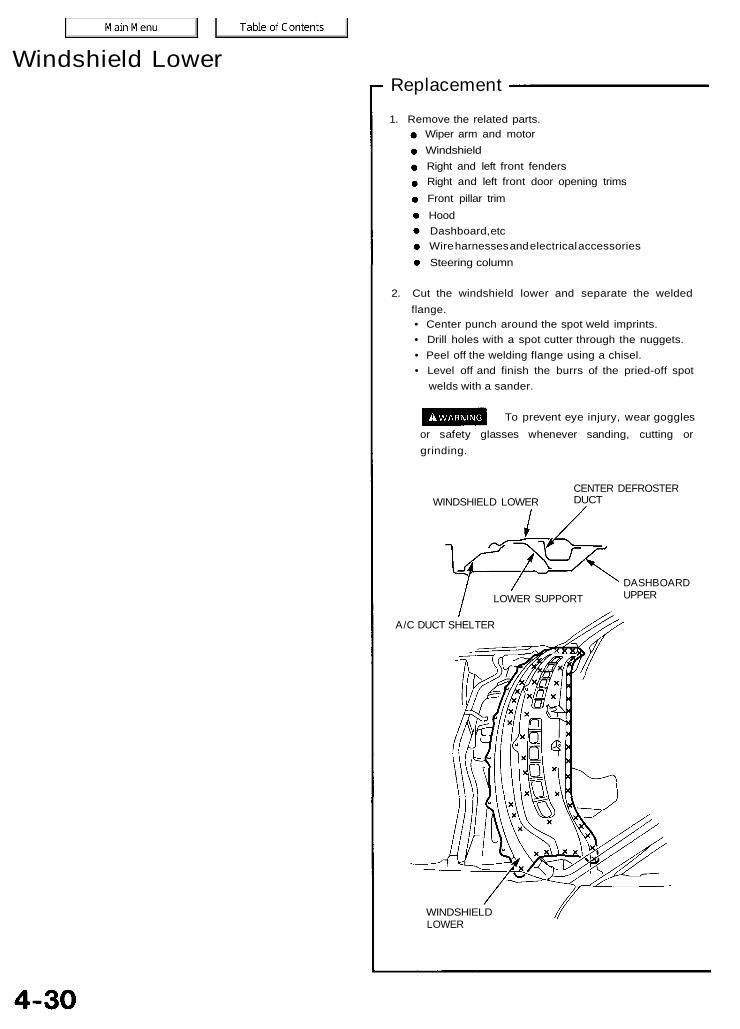
Windshield LowerDescription
Impact damage to the windshield lower area may spread tothe back of the panel and wiper mounting area, calling forreplacement of the affected skins.
Mass Production Body Welding Diagram
Windshield LowerReplacement
WINDSHIELD LOWERCENTER DEFROSTERDUCT
DASHBOARDUPPER
A/C DUCT SHELTER
WINDSHIELDLOWER
1. Remove the related parts.Wiper arm and motorWindshieldRight and left front fendersRight and left front door opening trimsFront pillar trimHoodDashboard, etcWire harnesses and electrical accessoriesSteering column
2. Cut the windshield lower and separate the weldedflange.• Center punch around the spot weld imprints.• Drill holes with a spot cutter through the nuggets.• Peel off the welding flange using a chisel.• Level off and finish the burrs of the pried-off spot
welds with a sander.
To prevent eye injury, wear gogglesor safety glasses whenever sanding, cutting orgrinding.
LOWER SUPPORT
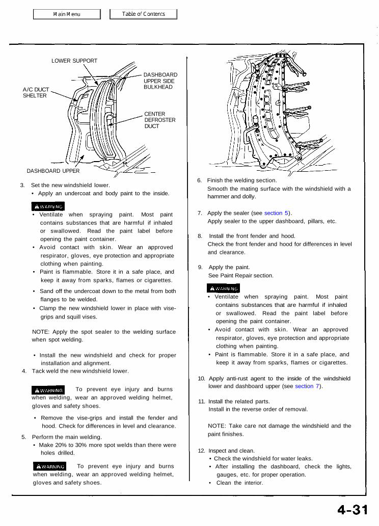
LOWER SUPPORT
A/C DUCTSHELTER
DASHBOARDUPPER SIDEBULKHEAD
CENTERDEFROSTERDUCT
DASHBOARD UPPER
3. Set the new windshield lower.• Apply an undercoat and body paint to the inside.
• Ventilate when spraying paint. Most paintcontains substances that are harmful if inhaledor swallowed. Read the paint label beforeopening the paint container.
• Avoid contact with skin. Wear an approvedrespirator, gloves, eye protection and appropriateclothing when painting.
• Paint is flammable. Store it in a safe place, andkeep it away from sparks, flames or cigarettes.
• Sand off the undercoat down to the metal from bothflanges to be welded.
• Clamp the new windshield lower in place with vise-grips and squill vises.
NOTE: Apply the spot sealer to the welding surfacewhen spot welding.
• Install the new windshield and check for properinstallation and alignment.
4. Tack weld the new windshield lower.
To prevent eye injury and burnswhen welding, wear an approved welding helmet,gloves and safety shoes.
• Remove the vise-grips and install the fender andhood. Check for differences in level and clearance.
5. Perform the main welding.• Make 20% to 30% more spot welds than there were
holes drilled.
To prevent eye injury and burnswhen welding, wear an approved welding helmet,gloves and safety shoes.
6. Finish the welding section.Smooth the mating surface with the windshield with ahammer and dolly.
7. Apply the sealer (see section 5).Apply sealer to the upper dashboard, pillars, etc.
8. Install the front fender and hood.Check the front fender and hood for differences in leveland clearance.
9. Apply the paint.See Paint Repair section.
• Ventilate when spraying paint. Most paintcontains substances that are harmful if inhaledor swallowed. Read the paint label beforeopening the paint container.
• Avoid contact with skin. Wear an approvedrespirator, gloves, eye protection and appropriateclothing when painting.
• Paint is flammable. Store it in a safe place, andkeep it away from sparks, flames or cigarettes.
10. Apply anti-rust agent to the inside of the windshieldlower and dashboard upper (see section 7).
11. Install the related parts.Install in the reverse order of removal.
NOTE: Take care not damage the windshield and thepaint finishes.
12. Inspect and clean.• Check the windshield for water leaks.• After installing the dashboard, check the lights,
gauges, etc. for proper operation.• Clean the interior.
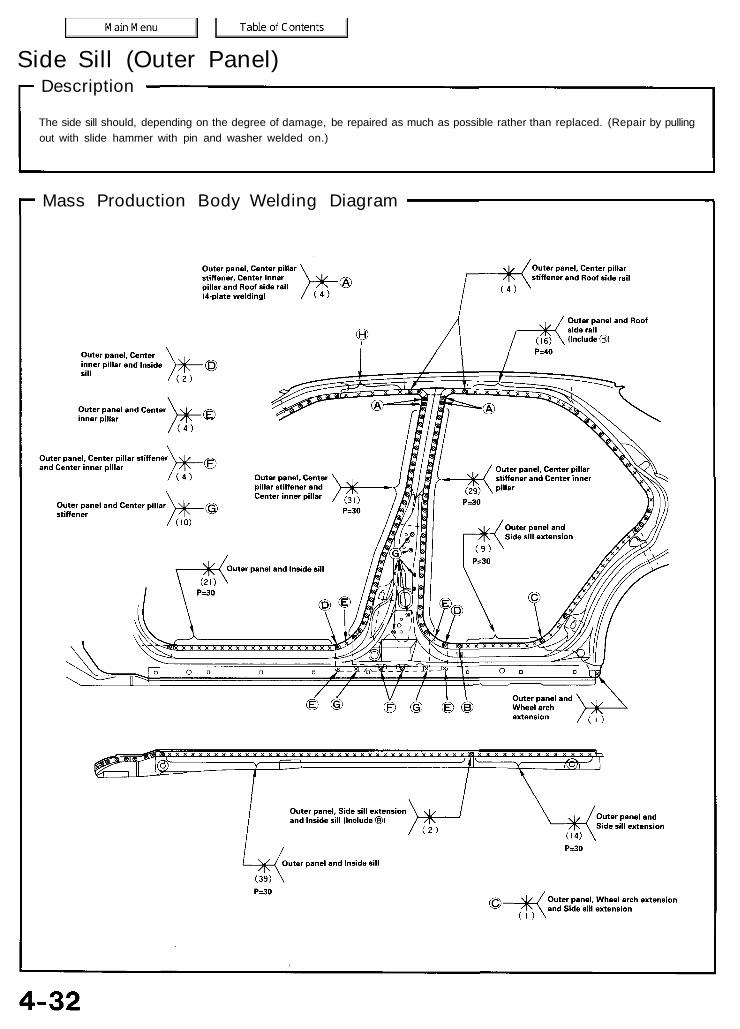
Side Sill (Outer Panel)Description
The side sill should, depending on the degree of damage, be repaired as much as possible rather than replaced. (Repair by pullingout with slide hammer with pin and washer welded on.)
Mass Production Body Welding Diagram

Replacement
1. Remove the related parts.• Front and rear doors
(remove according to part damaged)• Side and center pillar trim• Door opening trim• Carpet• Door switch• Seat belt
2. Pull out and straighten the damaged area.Damage may extend to the inner pillar, the inside sill andfloor. Determine the extent of the damage first, so thatthe frame can be pulled out properly.
3. Cut and pry off the side sill.• Check the damage on the outer side sill, then cut the
repair outer side sill so it will overlap by 30 mm (1.2 in)in the front and back.
• Cut the side sill with a handsaw along the bold lineshown in the figure to the right.
NOTE: Be careful not to cut the inside sill. This couldresult in extensive repair.
REPAIRPART
REPAIRPART
30 mm(1.2 in)
REPAIRPART
• If the damage involves part of the center pillar andrear wheel arch, cut them as shown with a handsaw.
• Cut the side sill with a chisel leaving the weld flangesintact.
• Center punch around the spot weld imprints on thewelded flange.
• Drill holes using the spot cutter.• Pry off the welded flange with a chisel.
NOTE: Be careful not to let the holes penetrate down tothe inner section.
SIDE SILLOUTER PANEL
OUTERPANEL
CENTER PILLAROUTER
CENTER INNERPILLAR
30 mm(1.2 in)
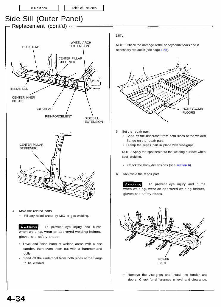
Side Sill (Outer Panel)Replacement (cont'd)
BULKHEADWHEEL ARCHEXTENSION
INSIDE SILL
CENTER INNERPILLAR
BULKHEAD
REINFORCEMENT SIDE SILLEXTENSION
CENTER PILLARSTIFFENER
4. Mold the related parts.• Fill any holed areas by MIG or gas welding.
To prevent eye injury and burnswhen welding, wear an approved welding helmet,gloves and safety shoes.
• Level and finish burrs at welded areas with a discsander, then even them out with a hammer anddolly.
• Sand off the undercoat from both sides of the flangeto be welded.
2.5TL:
NOTE: Check the damage of the honeycomb floors and ifnecessary replace it (see page 4-58).
HONEYCOMBFLOORS
5. Set the repair part.• Sand off the undercoat from both sides of the welded
flange on the repair part.• Clamp the repair part in place with vise-grips.
NOTE: Apply the spot sealer to the welding surface whenspot welding.
• Check the body dimensions (see section 6).
6. Tack weld the repair part.
To prevent eye injury and burnswhen welding, wear an approved welding helmet,gloves and safety shoes.
REPAIRPART
• Remove the vise-grips and install the fender anddoors. Check for differences in level and clearance.
CENTER PILLARSTIFFENER

7. Perform main welding.
To prevent eye injury and burnswhen welding, wear an approved welding helmet,gloves and safety shoes.
• Weld the side sill and rear side outer joints with a MIGwelder.
• Spot weld the side sill flanges.• Make 20% to 30% more spot welds than there were
holes drilled.• Make 5 mm (0.2 in) holes in the MIG weld holes with
the repair part, and weld the center pillar stiffener andwheel arch extension with a MIG welder.
• Level the weld beads at the front and rear with a discsander. Hammer down the projections, then fill withsolder or putty to finish it.
8. Apply the sealer.Apply sealer to the mating surfaces of the floor andinside sill (see section 5).
9. Apply the paint.See Paint Repair section.
• Ventilate when spraying paint. Most paintcontains substances that are harmful if inhaledor swallowed. Read the paint label beforeopening the paint container.
• Avoid contact with skin. Wear an approvedrespirator, gloves, eye protection and appropriateclothing when painting.
• Paint is flammable. Store it in a safe place, andkeep it away from sparks, flames or cigarettes.
10. Apply the undercoat.Undercoat the front floor, and apply an anti-rust agentto the inside of the side sill and center pillar (see section7).
11. Install the related parts.• Install in the reverse order of removal.• Check the door for proper installation and level
differences from the fenders.
12. Clean and check.Clean the passenger compartment and check for waterleaks.
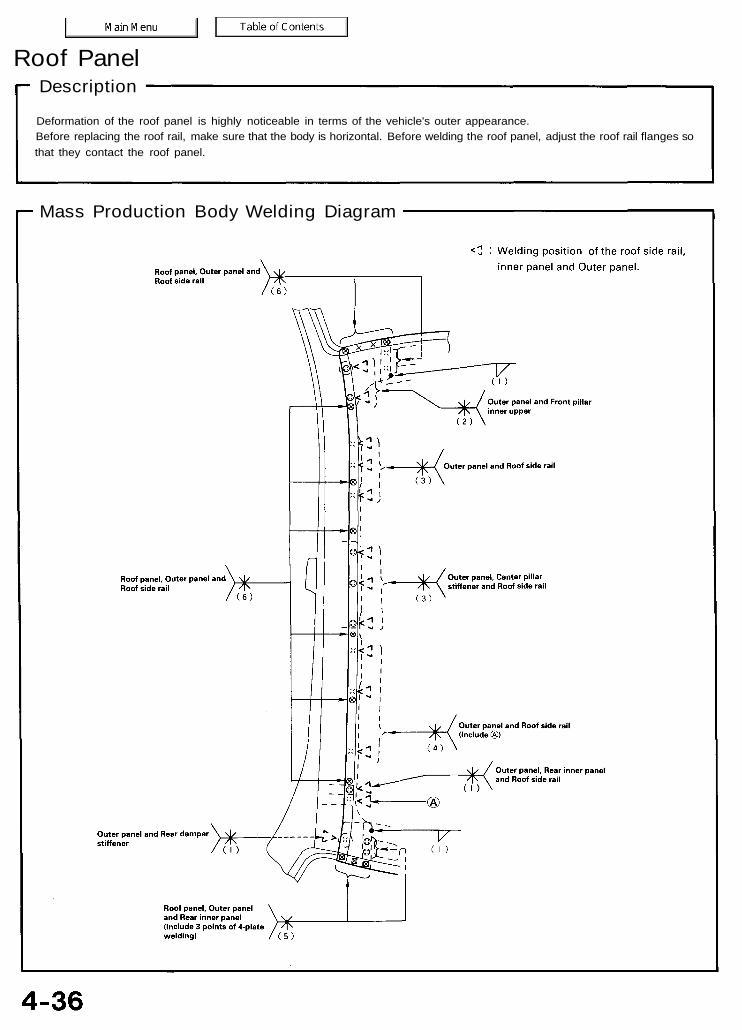
Roof PanelDescription
Deformation of the roof panel is highly noticeable in terms of the vehicle's outer appearance.Before replacing the roof rail, make sure that the body is horizontal. Before welding the roof panel, adjust the roof rail flanges sothat they contact the roof panel.
Mass Production Body Welding Diagram

Replacement
1. Remove the related parts.
WindshieldRear windowSunvisorCeiling lightsHeadlinerMoonroof frame (For some types)
2. Pull out and straighten the damaged area to approxi-mately the original shape.
NOTE: Check the inner front pillar and the inner centerpillar for position and damage.Cut the roof panel and pull out the pillars if necessary.
• Pull out the damaged area with the frame straight-ener before removing the roof panel.
• Attach the car to the frame straightener by tighten-ing the underbody clamps located at the horizontalpinch welds.
3. Keep the body level.
NOTE: Refer to the 95-96 Acura 2.5TL & 96 Acura 3.2TLService Manuals for safety stand location points.Jack-up the body at the front and back. Place safetystands at the four designated places of the side sills.
NOTE: Make sure that the right and left pillars areparallel with the windshield surface. Check the door forproper opening and closing.
4. Cut off the shaded areas of the roof panel.• Cut the roof rail weld flange with a handsaw at the
four corners.• Using a chisel, pry off the roof panel along the bold
lines as shown.• Center punch around the spot weld imprints of the
roof gutter welded flange.• Drill holes using the spot cutter.• Using a chisel, pry off the welded flange.
OUTER PANEL
ROOF PANEL
FRONT ROOFUPPER RAIL
ROOF PANELREAR ROOFUPPER RAIL
ForwardREAR ROOFLOWER RAIL
• Weld the holed areas with a MIG or gas welder.
To prevent eye injury and burnswhen welding, wear an approved welding helmet,gloves and safety shoes.
ROOF SIDE RAIL
Roof PanelReplacement (cont'd)
Level and finish burrs on the welded flanges with adisc sander.
To prevent eye injury, wear gogglesor safety glasses whenever sanding, cutting orgrinding.
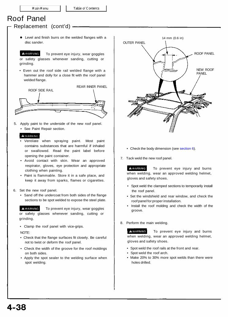
• Even out the roof side rail welded flange with ahammer and dolly for a close fit with the roof panelwelded flange.
REAR INNER PANELROOF SIDE RAIL
5. Apply paint to the underside of the new roof panel.• See Paint Repair section.
• Ventilate when spraying paint. Most paintcontains substances that are harmful if inhaledor swallowed. Read the paint label beforeopening the paint container.
• Avoid contact with skin. Wear an approvedrespirator, gloves, eye protection and appropriateclothing when painting.
• Paint is flammable. Store it in a safe place, andkeep it away from sparks, flames or cigarettes.
6. Set the new roof panel.• Sand off the undercoat from both sides of the flange
sections to be spot welded to expose the steel plate.
To prevent eye injury, wear gogglesor safety glasses whenever sanding, cutting orgrinding.
• Clamp the roof panel with vice-grips.
NOTE:• Check that the flange surfaces fit closely. Be careful
not to twist or deform the roof panel.
• Check the width of the groove for the roof moldingson both sides.
• Apply the spot sealer to the welding surface whenspot welding.
14 mm (0.6 in)OUTER PANEL
ROOF PANEL
NEW ROOFPANEL
• Check the body dimension (see section 6).
7. Tack weld the new roof panel.
To prevent eye injury and burnswhen welding, wear an approved welding helmet,gloves and safety shoes.
• Spot weld the clamped sections to temporarily installthe roof panel.
• Set the windshield and rear window, and check theroof panel for proper installation.
• Install the roof molding and check the width of thegroove.
8. Perform the main welding.
To prevent eye injury and burnswhen welding, wear an approved welding helmet,gloves and safety shoes.
• Spot weld the roof rails at the front and rear.• Spot weld the roof arch.• Make 20% to 30% more spot welds than there were
holes drilled.

• Smooth the spot weld areas under the windshield andrear window with a hammer and dolly.
NOTE: After welding the pillars, grind and finish thewelded areas flat and blend them into the roof panel.
Weld the roof rail from the inside by MIG welding asshown.
To prevent eye injury and burnswhen welding, wear an approved welding helmet,gloves and safety shoes.
<Front> Forward
9. Apply and level the sealer to the welded areas.
10. Apply the paint.See Paint Repair section.
• Ventilate when spraying paint. Most paintcontains substances that are harmful if inhaledor swallowed. Read the paint label beforeopening the paint container.
• Avoid contact with skin. Wear an approvedrespirator, gloves, eye protection and appropriateclothing when painting.
• Paint is flammable. Store it in a safe place, andkeep it away from sparks, flames or cigarettes.
11. Apply an anti-rust agent to the inside of the roof side rail.
12. Install the related parts.Install in the reverse order of removal.
13. Check and clean.• Check the windshield and rear window for water
leaks.• Make sure the moonroof operates smoothly.• Clean the passenger compartment thoroughly.

Rear Side Outer PanelDescription
The rear side outer panel is a conspicuous part of the vehicle. It is especially important for body line continuing from the door.Therefore, pay particular attention to it when conducting work. This part also is next to the trunk lid, door and rear window and otherparts and must be aligned with them.
Mass Production Body Welding Diagram
Replacement
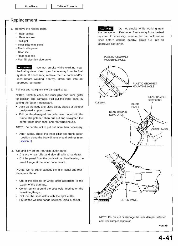
1. Remove the related parts.
• Rear bumper• Rear window• Taillight• Rear pillar trim panel• Trunk side panel• Rear seat• Rear seat belt• Fuel fill pipe (left side only)
Do not smoke while working nearthe fuel system. Keep open flame away from the fuelsystem. If necessary, remove the fuel tank and/orlines before welding nearby. Drain fuel into anapproved container.
2. Pull out and straighten the damaged area.
NOTE: Carefully check the inner pillar and trunk gutterfor position and damage. Pull out the inner panel bycutting the outer if necessary.• Jack-up the body and place safety stands at the four
designated support points.• Pull out the damaged rear side outer panel with the
frame straightener, then pull out and straighten thecenter pillar inner panel and rear wheelhouse.
NOTE: Be careful not to pull out more than necessary.
• After pulling, check the inner pillar and trunk gutterposition using the body dimensional drawings (seesection 6).
3. Cut and pry off the rear side outer panel.• Cut at the rear pillar and side sill with a handsaw.• Cut the panel from the body with a chisel leaving the
weld flange at the inner panel intact.
NOTE: Do not cut or damage the inner panel and reardamper stiffener.
• Cut at the side sill or wheel arch according to theextent of the damage.
• Center punch around the spot weld imprints on theremaining flange.
• Drill out the spot welds with the spot cutter.• Pry off the welded flange sections using a chisel.
Do not smoke while working nearthe fuel system. Keep open flame away from the fuelsystem. If necessary, remove the fuel tank and/orlines before welding nearby. Drain fuel into anapproved container.
PLASTIC GROMMETMOUNTING HOLE
PLASTIC GROMMETMOUNTING HOLE
REAR DAMPERSTIFFENER
Cut area. INNERPANEL
REAR DAMPERSEPARATOR
OUTER PANEL
NOTE: Do not cut or damage the rear damper stiffenerand rear damper separator.
OUTER PANEL
Rear Side Outer PanelReplacement (cont'd)
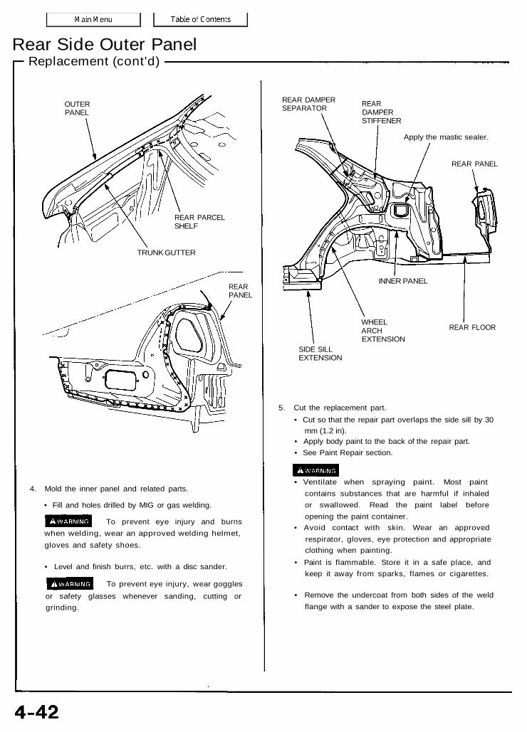
OUTERPANEL
REAR PARCELSHELF
TRUNK GUTTER
REARPANEL
4. Mold the inner panel and related parts.
• Fill and holes drilled by MIG or gas welding.
To prevent eye injury and burnswhen welding, wear an approved welding helmet,gloves and safety shoes.
• Level and finish burrs, etc. with a disc sander.
To prevent eye injury, wear gogglesor safety glasses whenever sanding, cutting orgrinding.
REAR DAMPERSEPARATOR REAR
DAMPERSTIFFENER
Apply the mastic sealer.
REAR PANEL
WHEELARCHEXTENSION
REAR FLOOR
SIDE SILLEXTENSION
5. Cut the replacement part.• Cut so that the repair part overlaps the side sill by 30
mm (1.2 in).• Apply body paint to the back of the repair part.• See Paint Repair section.
• Ventilate when spraying paint. Most paintcontains substances that are harmful if inhaledor swallowed. Read the paint label beforeopening the paint container.
• Avoid contact with skin. Wear an approvedrespirator, gloves, eye protection and appropriateclothing when painting.
• Paint is flammable. Store it in a safe place, andkeep it away from sparks, flames or cigarettes.
• Remove the undercoat from both sides of the weldflange with a sander to expose the steel plate.
INNER PANEL

REPAIR PART
6. Set the repair part.• Install the outer panel and clamp it with vise-grips.
NOTE: Apply the spot sealer to the welding surface whenspot welding.
• Check the body dimensions (see section 6).
7. Tack weld the repair part.
To prevent eye injury and burnswhen welding, wear an approved welding helmet,gloves and safety shoes.
Temporarily spot weld the panel at the clamped posi-tions.
8. Remove the vise-grips and check the alignment of thedoor and trunk lid.
NOTE:• Check for flushness of the front fender, door, and
the rear fender and make sure the body lines flowsmoothly.
• Check the rear window openings.
9. Perform the main welding.
To prevent eye injury and burnswhen welding, wear an approved welding helmet,gloves and safety shoes.
• Weld the outer panel at the rear pillar and side sill witha MIG welder.
• Make 20% to 30% more spot welds than there wereholes drilled.
• Make 5 mm (0.2 in) hole in the MIG weld hole with therepair part, and the wheel arch extension with a MIGwelder.

Rear Side Outer PanelReplacement (cont'd)
10. Finish the welded areas.
• Level the MIG welded areas with a disc sander.
To prevent eye injury, wear gogglesor safety glasses whenever sanding, cutting orgrinding.
• Even out high areas with a hammer. Be careful not todeform them.
• Even out the spot welded flange areas with a ham-mer and dolly.
• Fill in deformations and level differences of thewelded areas with solder or putty, then finish.
11. Apply the sealer (see section 5).
Apply sealer to the fuel fill section, trunk lid openingjoint and around the taillight area of the rear panel.
12. Apply the paint.See Paint Repair section.
• Ventilate when spraying paint. Most paintcontains substances that are harmful if inhaledor swallowed. Read the paint label beforeopening the paint container.
• Avoid contact with skin. Wear an approvedrespirator, gloves, eye protection and appropriateclothing when painting.
• Paint is flammable. Store it in a safe place, andkeep it away from sparks, flames or cigarettes.
13. Apply the undercoat.Apply undercoat to the wheelhouse and apply anti-rustagent to the inside of the outer panel (see section 7).
14. Install the related parts.Install in the reverse order in which they were removed.
15. Inspect, check, and clean.• Adjust the clearance with the door and trunk lid, then
adjust the level differences and fit. Check operation.• Test for leaks in the trunk and passenger compart-
ments.• Clean the trunk floor.

Rear PanelDescription
The rear panel is joined to the rear outer panel and rear floor, and maintains the rigidity of both sides of the rear body. It mustbe welded carefully.
Mass Production Body Welding Diagram

Rear PanelReplacement
1. Remove the related parts.
• Rear bumper• Rear bumper upper beam• Trunk lid lock and its attachments• Other related parts• Rear and side trim panels• Taillights
2. Pull out and straighten the damaged area.• Pull out the related rear side inner panel, rear floor,
rear side frame and other damaged parts with theframe straightener.
• Attach the car to the frame straightener by tighten-ing the underbody clamps located at the jack-uppoints on the bottom of the side sill and the side sillside flanges.
3. Cut and pry off the rear panel.• Cut along the bold line shown with a gas cutter or an
air chisel and remove the rear panel.
• Center punch around the spot weld imprints with therear side outer panel and rear floor.
• Drill holes using the spot cutter.
NOTE: Be careful not to let holes penetrate through tothe rear floor.
• Remove weld flange with a chisel.
REARPANEL
JACK-UPSTIFFENER
4. Mold the related parts.
• Repair the rear floor upper stiffener if necessary.
• Repair all cracks, holes or other defects by MIG orgas welding.
To prevent eye injury and burnswhen welding, wear an approved welding helmet,gloves and safety shoes.
REAR FLOORJACK-UPSTIFFENER
REARFRAME
SILENCER MOUNTBRACKET
REAR FLOORUPPERSTIFFENER
5. Set the new rear panel.• Paint the inside of the panel with the body color.• See Paint Repair section.
• Ventilate when spraying paint. Most paintcontains substances that are harmful if inhaledor swallowed. Read the paint label beforeopening the paint container.
• Avoid contact with skin. Wear an approvedrespirator, gloves, eye protection and appropriateclothing when painting.
• Paint is flammable. Store it in a safe place, andkeep it away from sparks, flames or cigarettes.
• Remove the undercoat from the welding section ofthe panel and expose the steel plate using a discsander.
To prevent eye injury, wear gogglesor safety glasses whenever sanding, cutting orgrinding.
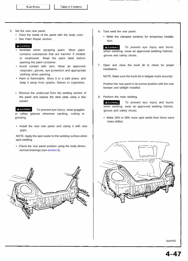
• Install the new rear panel and clamp it with vise-grips.
NOTE: Apply the spot sealer to the welding surface whenspot welding.
• Check the rear panel position using the body dimen-sionnal drawings (see section 6).
6. Tack weld the rear panel.
• Weld the clamped sections for temporary installa-tion.
To prevent eye injury and burnswhen welding, wear an approved welding helmet,gloves and safety shoes.
7. Open and close the trunk lid to check for properinstallation.
NOTE: Make sure the trunk lid or tailgate locks securely.
Position the rear panel in its correct position with the rearbumper and taillight installed.
8. Perform the main welding.
To prevent eye injury and burnswhen welding, wear an approved welding helmet,gloves and safety shoes.
• Make 20% to 30% more spot welds than there wereholes drilled.
Rear PanelReplacement (cont'd)
9. Finish the welding areas.• Level the welded acres with a disc sander, then even
out high areas with a hammer. Be careful not to de-form them.
To prevent eye injury, wear gogglesor safety glasses whenever sanding, cutting orgrinding.
• Even out the spot welded flange area with a hammerand dolly.
10. Apply the sealer (see section 5).• Apply sealer to the rear side outer joint and around
the taillight areas of the rear panel.• Apply sealer to the rear panel and rear floor joint.
11. Apply the paint.See Paint Repair section.
• Ventilate when spraying paint. Most paintcontains substances that are harmful if inhaledor swallowed. Read the paint label beforeopening the paint container.
• Avoid contact with skin. Wear an approvedrespirator, gloves, eye protection and appropriateclothing when painting.
• Paint is flammable. Store it in a safe place, andkeep it away from sparks, flames or cigarettes.
12. Apply anti-rust agent (see section 7).• Apply agent to the outer panel, rear panel and rear
floor joint.• Apply agent to the inside of the jack-up stiffener.
13. Install the related parts.Install in the reverse order in which they were removed.
14. Inspect, check, and clean.• Adjust the clearance with the trunk lid, then adjust the
level difference and fit. Check operation.• Test for leaks in the trunk compartment.• Clean the trunk floor.

Rear FloorDescription
The rear floor is the base of the rear body and it is critical for the rigidity of the rear body. During replacement, refer to the bodydimension chart or body correction chart and determine the position to set the rear floor properly. Be sure that the rear floor isnot bent or deformed. Weld securely following the welder manufacturer's instructions to maintain the rigidity of the body.
Mass Production Body Welding Diagram

Rear FloorReplacement
1. Remove the related parts.• Rear seat• Trim and other luggage compartment fittings• Left and right rear suspension assembly• Parking brake parts• Muffler• Wire harness• Other parts as necessary• Fuel tank and fuel pipes
Do not smoke while working nearthe fuel system. Keep open flame away from the fuelsystem. If necessary, remove the fuel tank and/orlines before welding nearby. Drain fuel into anapproved container.
2. Remove the rear suspension cross beam.
3. Remove the rear floor upper extensions.
4. Pull out and straighten the damaged area.• Check whether the damage extended to the rear
floor cross member, rear wheelhouse and the pas-senger compartment, and pull out the damagedparts using the frame corrector.
• Impact damage to the rear floor spreads to relatedparts such as the rear frame, rear floor cross memberand rear wheelhouse.
• Therefore, pull out the damaged areas with theframe straightener and measure in reference to bodydimensional drawing.
NOTE: Use of a positioning jig is recommended (seepage 1-7).
5. Peel off the undercoat.Heat the undercoat at the weld areas of the lower rearfloor with a gas torch and peel off the undercoat with ametal spatula.
CAUTION: Be careful not to burn the fittings inside thetrunk compartment while heating.
6. Cut and pry off the rear panel (see page 4-45).
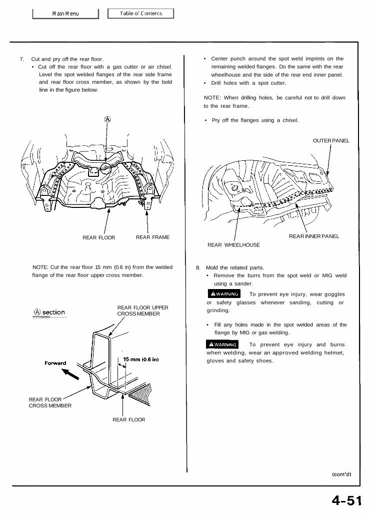
7. Cut and pry off the rear floor.• Cut off the rear floor with a gas cutter or air chisel.
Level the spot welded flanges of the rear side frameand rear floor cross member, as shown by the boldline in the figure below.
REAR FLOOR REAR FRAME
NOTE: Cut the rear floor 15 mm (0.6 in) from the weldedflange of the rear floor upper cross member.
REAR FLOOR UPPERCROSS MEMBER
REAR FLOORCROSS MEMBER
REAR FLOOR
• Center punch around the spot weld imprints on theremaining welded flanges. Do the same with the rearwheelhouse and the side of the rear end inner panel.
• Drill holes with a spot cutter.
NOTE: When drilling holes, be careful not to drill downto the rear frame.
• Pry off the flanges using a chisel.
OUTER PANEL
REAR INNER PANELREAR WHEELHOUSE
8. Mold the related parts.• Remove the burrs from the spot weld or MIG weld
using a sander.
To prevent eye injury, wear gogglesor safety glasses whenever sanding, cutting orgrinding.
• Fill any holes made in the spot welded areas of theflange by MIG or gas welding.
To prevent eye injury and burnswhen welding, wear an approved welding helmet,gloves and safety shoes.
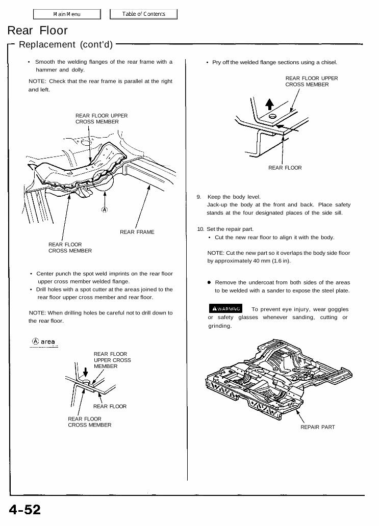
Rear FloorReplacement (cont'd)
• Smooth the welding flanges of the rear frame with ahammer and dolly.
NOTE: Check that the rear frame is parallel at the rightand left.
REAR FLOOR UPPERCROSS MEMBER
REAR FRAME
REAR FLOORCROSS MEMBER
• Center punch the spot weld imprints on the rear floorupper cross member welded flange.
• Drill holes with a spot cutter at the areas joined to therear floor upper cross member and rear floor.
NOTE: When drilling holes be careful not to drill down tothe rear floor.
REAR FLOORUPPER CROSSMEMBER
REAR FLOOR
REAR FLOORCROSS MEMBER
• Pry off the welded flange sections using a chisel.
REAR FLOOR UPPERCROSS MEMBER
REAR FLOOR
9. Keep the body level.Jack-up the body at the front and back. Place safetystands at the four designated places of the side sill.
10. Set the repair part.• Cut the new rear floor to align it with the body.
NOTE: Cut the new part so it overlaps the body side floorby approximately 40 mm (1.6 in).
Remove the undercoat from both sides of the areasto be welded with a sander to expose the steel plate.
To prevent eye injury, wear gogglesor safety glasses whenever sanding, cutting orgrinding.
REPAIR PART

• Insert the repair part between the rear floor and rearfloor upper cross member.
• Check that the weld flange surfaces fit closely.
REAR FLOORUPPER CROSSMEMBER
REPAIRPART
REAR FLOORCROSS MEMBER
REARFLOOR
• Check the position of the rear floor and rear frames usingthe body dimensional drawings (see section 6) and thepositioning jig.
REAR FLOORUPPER CROSSMEMBER
REPAIRPART
REAR FLOOR REAR FLOORCROSS MEMBER
11. Set the rear floor upper stiffener, and check the rear panelposition.
REAR FLOORUPPERSTIFFENER
12. Perform the main welding.
To prevent eye injury and burnswhen welding, wear an approved welding helmet,gloves and safety shoes.
Spot welding:
NOTE: Apply the spot sealer to the welding surface whenspot welding.
• Recheck the position of the rear frames and rear floor,then weld the repair part and rear frames.
• Make 20% to 30% more spot welds than there wereholes drilled.
MIG welding:
• Drill the holes for welding the repair part.• Check the rear frame position and weld the repair part
to the rear frames.

Rear FloorReplacement (cont'd)
• Make 5 mm (0.2 in) hole in the MIG weld hole with therepair part.
• Weld the rear floor, repair part and rear floor uppercross member.
REARFLOOR MIG
welding REPAIRPART
• Weld the rear wheelhouse and outer panel.
• Weld the rear panel and install the rear floor upperextension.
13. Finish the welded area.Even out the welded area with a hammer and dolly, andfit the flange surfaces closely together.
14. Apply the sealer.Apply sealer at the overlapped area of the rear floor, andthe welded surfaces of the rear wheelhouse and rearend inner panel. Seal gaps completely (see section 5).
15. Apply the paint.See Paint Repair section.
• Ventilate when spraying paint. Most paintcontains substances that are harmful if inhaledor swallowed. Read the paint label beforeopening the paint container.
• Avoid contact with skin. Wear an approvedrespirator, gloves, eye protection and appropriateclothing when painting.
• Paint is flammable. Store it in a safe place, andkeep it away from sparks, flames or cigarettes.
16. Apply the undercoat.Apply anti-rust agent to the inside of the jack-up stif-fener and jointed areas of the rear floor (see section 7).
17- Weld the rear panel and install the related parts.Install in the reverse order in which they were removed.
18. Inspect and clean.• Measure the rear wheel alignment.• Clean the inside of the trunk compartment.
REAR FLOORUPPER CROSSMEMBER

Rear Floor Cross MemberDescriptionThe rear floor cross member position is critical for rear wheel alignment. During replacement, check the position of the rear beamand rear damper base and position the rear floor cross member properly.Weld securely following the welder manufacturer's instructions to maintain rigidity. Use of the positioning jig is recommended.
Mass Production Body Welding Diagram
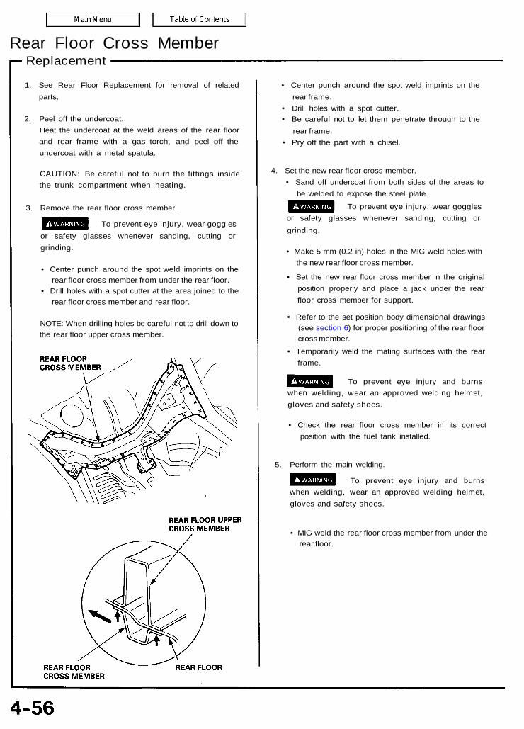
Rear Floor Cross MemberReplacement
1. See Rear Floor Replacement for removal of relatedparts.
2. Peel off the undercoat.Heat the undercoat at the weld areas of the rear floorand rear frame with a gas torch, and peel off theundercoat with a metal spatula.
CAUTION: Be careful not to burn the fittings insidethe trunk compartment when heating.
3. Remove the rear floor cross member.
To prevent eye injury, wear gogglesor safety glasses whenever sanding, cutting orgrinding.
• Center punch around the spot weld imprints on therear floor cross member from under the rear floor.
• Drill holes with a spot cutter at the area joined to therear floor cross member and rear floor.
NOTE: When drilling holes be careful not to drill down tothe rear floor upper cross member.
• Center punch around the spot weld imprints on therear frame.
• Drill holes with a spot cutter.• Be careful not to let them penetrate through to the
rear frame.• Pry off the part with a chisel.
4. Set the new rear floor cross member.• Sand off undercoat from both sides of the areas to
be welded to expose the steel plate.
To prevent eye injury, wear gogglesor safety glasses whenever sanding, cutting orgrinding.
• Make 5 mm (0.2 in) holes in the MIG weld holes withthe new rear floor cross member.
• Set the new rear floor cross member in the originalposition properly and place a jack under the rearfloor cross member for support.
• Refer to the set position body dimensional drawings(see section 6) for proper positioning of the rear floorcross member.
• Temporarily weld the mating surfaces with the rearframe.
To prevent eye injury and burnswhen welding, wear an approved welding helmet,gloves and safety shoes.
• Check the rear floor cross member in its correctposition with the fuel tank installed.
5. Perform the main welding.
To prevent eye injury and burnswhen welding, wear an approved welding helmet,gloves and safety shoes.
• MIG weld the rear floor cross member from under therear floor.

6. Finish the welding area.Roughly grind the welds in the trunk compartment witha disc grinder. Be sure to leave the finishing allowance.
NOTE: Take care not to grind excessively.
7. Apply the sealer (see section 5).
8. Apply the paint.See Paint Repair section.
• Ventilate when spraying paint. Most paintcontains substances that are harmful if inhaledor swallowed. Read the paint label beforeopening the paint container.
• Avoid contact with skin. Wear an approvedrespirator, gloves, eye protection and appropriateclothing when painting.
• Paint is flammable. Store it in a safe place, andkeep it away from sparks, flames or cigarettes.
9. Apply the undercoat (see section 7).
10. Install the related parts.Install in the reverse order of removal.
11. Check and clean.• Check the rear wheel alignment.• Clean the trunk compartment.

Honeycomb Floors (2.5TL)
NOTE: What is known as "honeycomb" construction is employed for the front floor. Properly designed and applied, it plays animportant role in maintaining the structural rigidity of that section of the car's floor. The honeycomb floor is installed with an epoxyresin adhesive. Care must be exercised when installing a new honeycomb floor as seepage of water into the honeycombconstruction will adversely affect its performance.
Replacement
1. Remove the related parts.• Front and rear seats.• Carpet, others
2. Removal of honeycomb floors.• Scrape off the dust sealer all the way around the
floor.• Separate the floor from the body by using a pair of
pliers.
3. Flattening of melt-sheet• Heat the surface of the melt-sheet with a torch or heat
gun until it becomes soft and pliable.• Finish the surface smooth and flat with a steel spatula.
NOTE: In order to take full advantage of the honeycombfloor, its face must contact the base fully.
CAUTION: Be careful not to burn the fittings insidethe passenger compartment when heating.

4. Application of adhesive.• Apply adhesive all over the melt-sheet.
NOTE: Use CEMEDINE EP-330 or equivalent (epoxyresin adhesive designed to harden quickly at normaltemperature). Follow the adhesive manufacturer'sinstructions.
6. Application of dust sealant.• Apply dust sealer all the way around the floors.
NOTE: It is essential to make the floor completely imper-vious to water as seepage into honeycomb constructionwill adversely affect its performance. Use sufficient dustsealant to seal the floor.
• Using a bristle brush or spatula, spread the dustsealant all over the surface until it becomes smoothand flat.
• Check that the dust sealant is applied to the seatbrackets thoroughly.
5. Installation of new honeycomb floors.• Install the new honeycomb floors.• Clamp the floor in place using a clamp at the front
and rear as shown.
NOTE: Place weights on the floor for 30-60 minutesuntil the adhesive hardens.
7. Apply the paint (body color).• See Paint Repair Manual.
• Ventilate when spraying paint. Most paintcontains substances that are harmful if inhaledor swallowed. Read the paint label beforeopening paint container.
• Avoid contact with skin. Wear an approvedrespirator, gloves, eye protection and appropriateclothing when painting.
• Paint is flammable. Store in a safe place, andkeep it away from sparks, flames or cigarettes.
8. Install the related parts.
9. Check and clean.Check the electrical parts for proper operation.
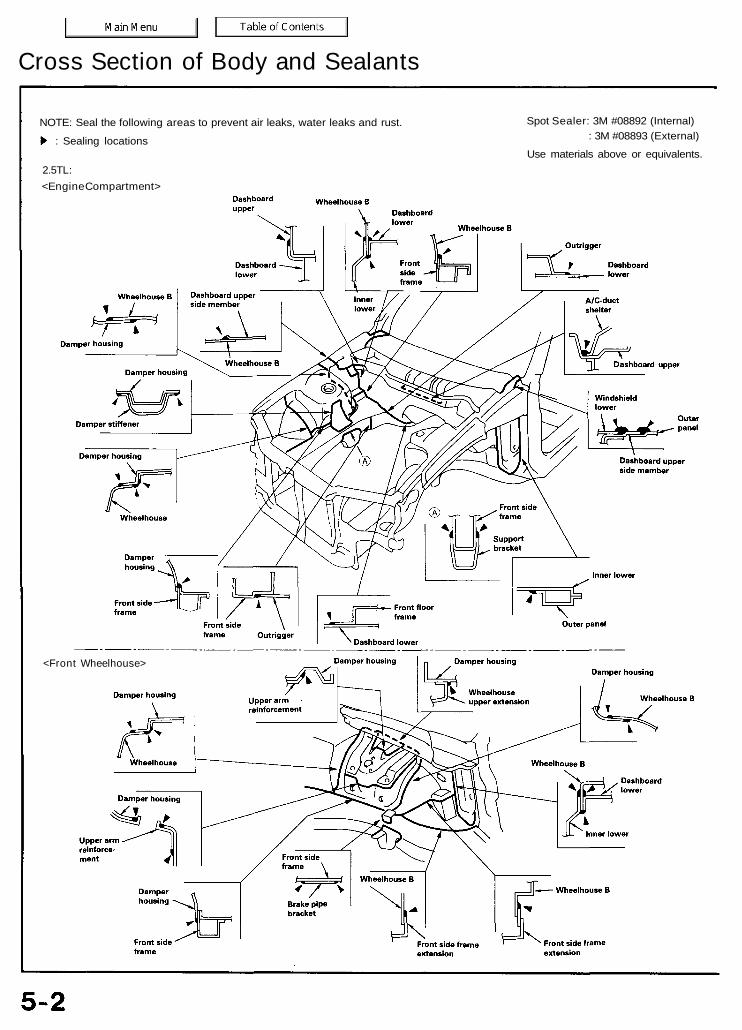
NOTE: Seal the following areas to prevent air leaks, water leaks and rust. Spot Sealer: 3M #08892 (Internal): 3M #08893 (External)
Use materials above or equivalents.: Sealing locations
2.5TL:<Engine Compartment>
<Front Wheelhouse>
Cross Section of Body and Sealants

<Front Floor/Rear Floor><Roof panel>
<Front Pillar Inner Panel>

2.5TL:<Outer Panel, Rear Floor/Rear Panel>
(cont'd)Cross Section of Body and Sealants

<Under Floor/Frame>

(cont'd)2.5TL:
<Hood>
Cross Section of Body and Sealants

3.2TL:
< Engine Compartment >
<Front Wheelhouse/Under floor>
NOTE: The sealing locations of except those above are the same as 2.5TL.

Spot/Mastic Sealers
NOTE: Seal the following areas to prevent air leaks, water
leaks and rust.
: Sealing locations
Cross Section of Body and Sealants
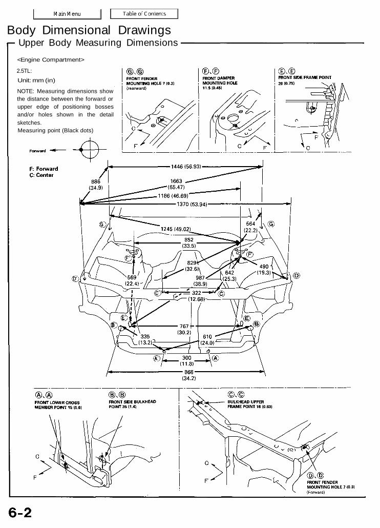
Upper Body Measuring DimensionsBody Dimensional Drawings
<Engine Compartment>
2.5TL:Unit: mm (in)
NOTE: Measuring dimensions showthe distance between the forward orupper edge of positioning bossesand/or holes shown in the detailsketches.Measuring point (Black dots)
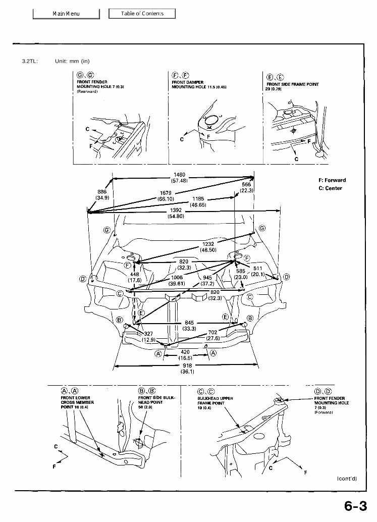
3.2TL: Unit: mm (in)

Upper Body Measuring Dimensions (cont'd)Body Dimensional Drawings
<Passenger Compartment>
Unit: mm (in)

2.5TL:
Unit: mm (in)
Under Body Measuring Dimensions
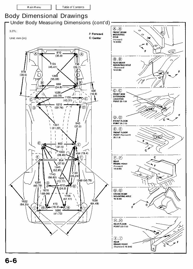
Under Body Measuring Dimensions (cont'd)3.2TL:
Unit: mm (in)
Body Dimensional Drawings
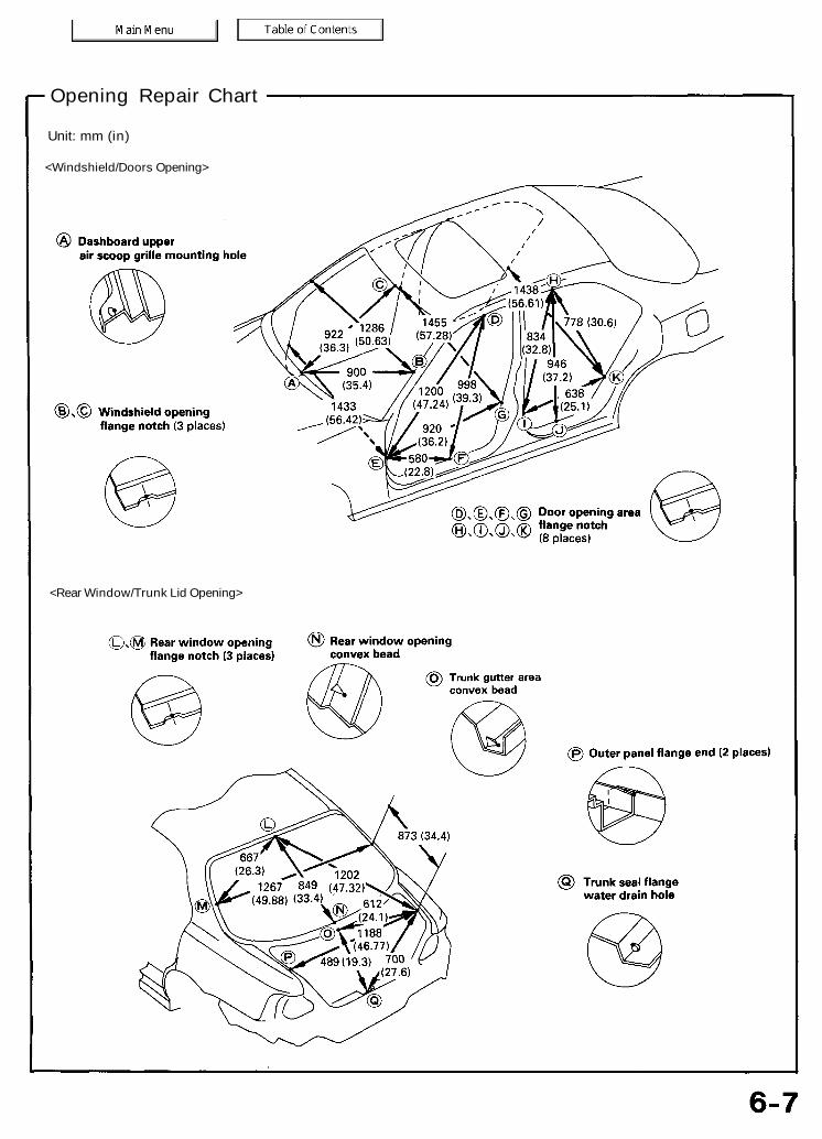
Opening Repair Chart
Unit: mm (in)
<Windshield/Doors Opening>
<Rear Window/Trunk Lid Opening>
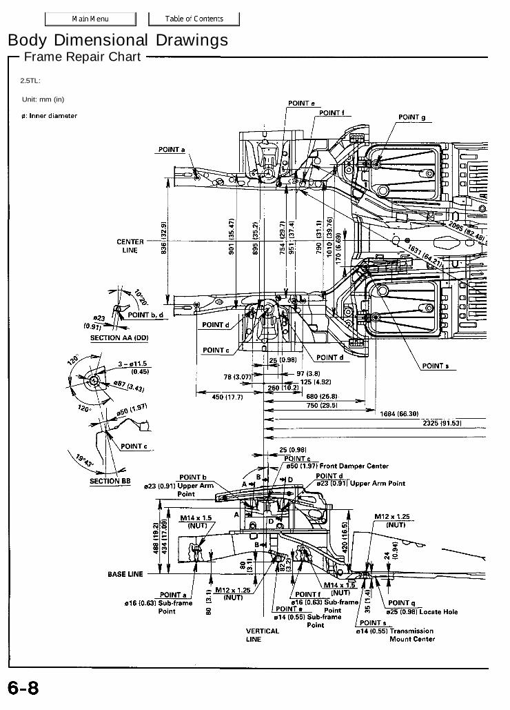
Frame Repair ChartBody Dimensional Drawings
2.5TL:
Unit: mm (in)


NOTE: The dimensions of the rear floor area are the same as the table on page 6-9.
3.2TL:
Frame Repair chartBody Dimensional Drawings
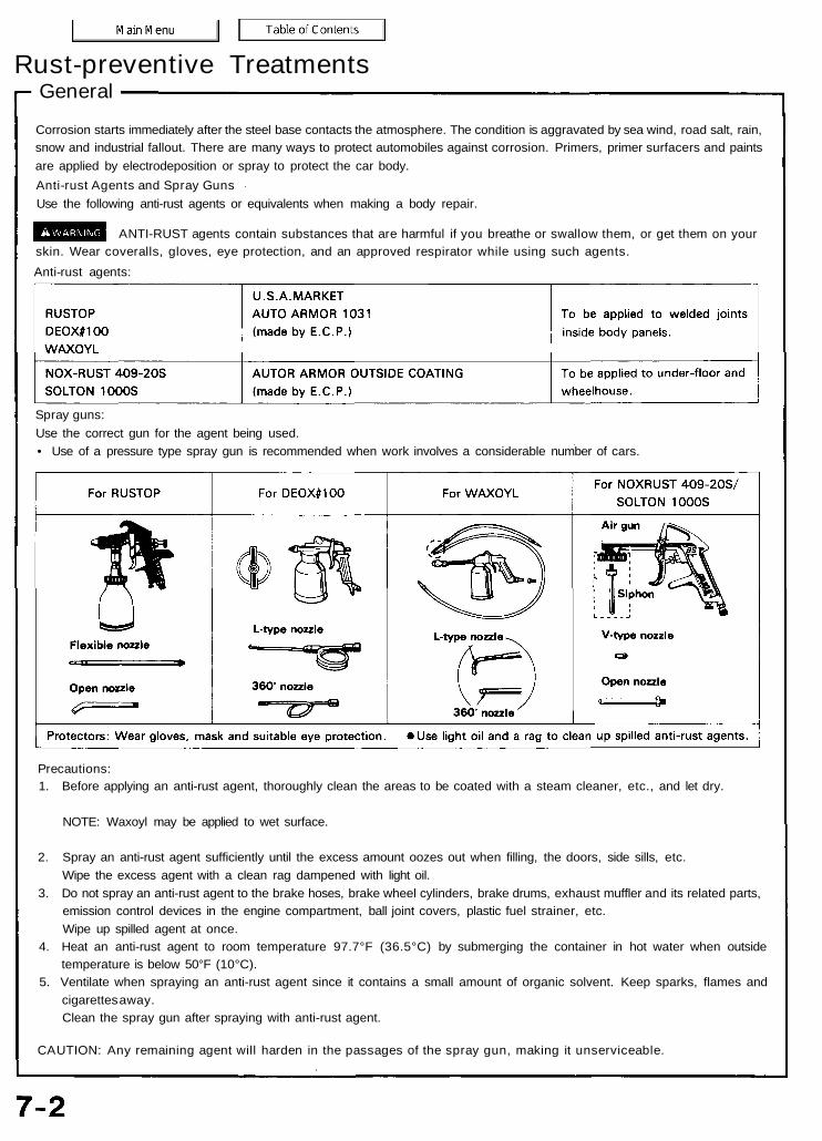
GeneralRust-preventive Treatments
Corrosion starts immediately after the steel base contacts the atmosphere. The condition is aggravated by sea wind, road salt, rain,snow and industrial fallout. There are many ways to protect automobiles against corrosion. Primers, primer surfacers and paintsare applied by electrodeposition or spray to protect the car body.Anti-rust Agents and Spray GunsUse the following anti-rust agents or equivalents when making a body repair.
ANTI-RUST agents contain substances that are harmful if you breathe or swallow them, or get them on yourskin. Wear coveralls, gloves, eye protection, and an approved respirator while using such agents.Anti-rust agents:
Spray guns:Use the correct gun for the agent being used.• Use of a pressure type spray gun is recommended when work involves a considerable number of cars.
Precautions:1. Before applying an anti-rust agent, thoroughly clean the areas to be coated with a steam cleaner, etc., and let dry.
NOTE: Waxoyl may be applied to wet surface.
2. Spray an anti-rust agent sufficiently until the excess amount oozes out when filling, the doors, side sills, etc.Wipe the excess agent with a clean rag dampened with light oil.
3. Do not spray an anti-rust agent to the brake hoses, brake wheel cylinders, brake drums, exhaust muffler and its related parts,emission control devices in the engine compartment, ball joint covers, plastic fuel strainer, etc.Wipe up spilled agent at once.
4. Heat an anti-rust agent to room temperature 97.7°F (36.5°C) by submerging the container in hot water when outsidetemperature is below 50°F (10°C).
5. Ventilate when spraying an anti-rust agent since it contains a small amount of organic solvent. Keep sparks, flames andcigarettes away.Clean the spray gun after spraying with anti-rust agent.
CAUTION: Any remaining agent will harden in the passages of the spray gun, making it unserviceable.
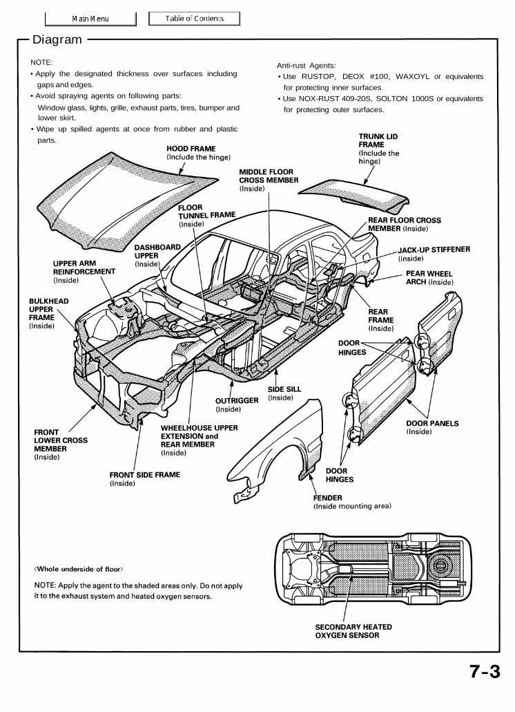
Anti-rust Agents:• Use RUSTOP, DEOX #100, WAXOYL or equivalents
for protecting inner surfaces.• Use NOX-RUST 409-20S, SOLTON 1000S or equivalents
for protecting outer surfaces.
NOTE:• Apply the designated thickness over surfaces including
gaps and edges.• Avoid spraying agents on following parts:
Window glass, lights, grille, exhaust parts, tires, bumper andlower skirt.
• Wipe up spilled agents at once from rubber and plasticparts.
Diagram

Areas to be Covered by Anti-rust AgentsRust-preventive Treatments
Rust-preventive Treatments:
Hood, Underside• Coat the entire panel and seams all the way around.• Spray sufficient anti-rust agent to the front area and
each corner.• Apply rust-preventive agent or grease to the hood
hinges.• Also coat the bulkhead upper frame and hood frame with
anti-rust agent.
Nozzles used: A and B
Front Bulkhead Area• With the hood opened, coat the joints of the bulkhead,
wheelhouse and side frame and around the back of theheadlight assembly.
Nozzle used: B
• Coat the inside of the front lower cross member.
Nozzles used: A and B
Dashboard Upper/Windshield Lower• Coat the windshield lower and dashboard upper water
drain with anti-rust agent at front, right and left.• Spray anti-rust agent completely over the rear of the
dashboard upper (windshield side).
NOTE: To insert the nozzle in the dashboard upper, removethe air scoop grille for easier, more thorough spraying.
Nozzles used: A and B

Front Fender, UndersideApply anti-rust agent to the end of the fender, wheelhouse,and side sill installation.
NOTE:
• Apply a coat of agent to the front door side, wheel archend.
• If the fender is to be removed, care take to avoid damagingthe paint finish. Apply agent to the entire surface of theback of the fender.
• Apply agent to the front fender filling pillar.
Nozzles used: B and C
Outside Panel (Front Pillar and Center Pillar), Inside• Remove the door harness grommet and insert the nozzle
facing down.NOTE: Make sure that the nozzle is not interfering with thedoor hinge bracket. Spray thoroughly.• Coat the door checker bracket.
Nozzles used: A and B
Front Pillar
Wheelhouse Upper Member, Inside
• Remove the front fender.• Remove the air scoop grille in the dashboard upper and
coat the inside of the wheelhouse upper member withanti-rust agent.
Nozzles used: A and B
Center Pillar
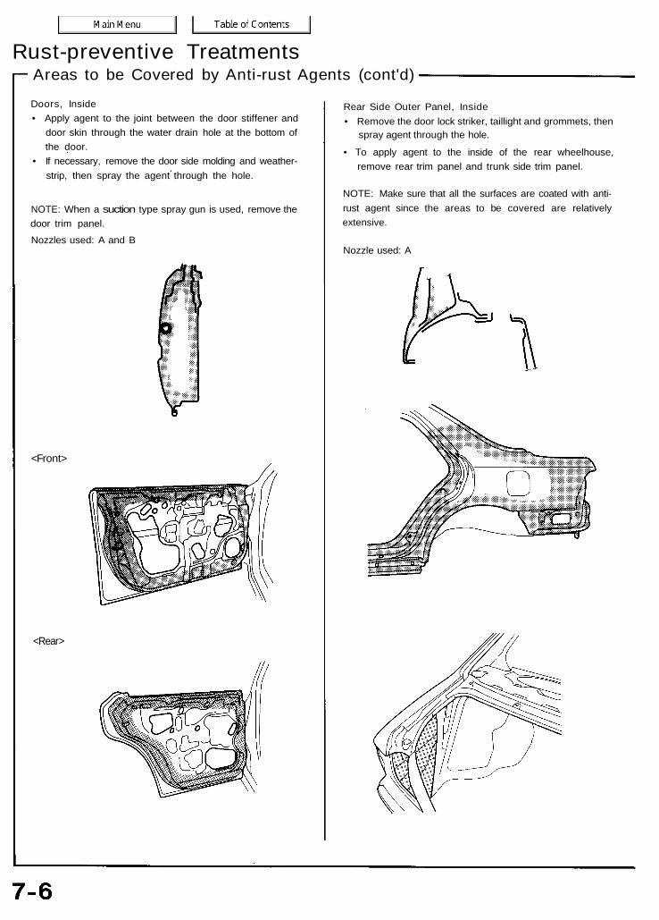
<Rear>
<Front>
Doors, Inside• Apply agent to the joint between the door stiffener and
door skin through the water drain hole at the bottom ofthe door.
• If necessary, remove the door side molding and weather-strip, then spray the agent through the hole.
NOTE: When a suction type spray gun is used, remove thedoor trim panel.Nozzles used: A and B
Rear Side Outer Panel, Inside• Remove the door lock striker, taillight and grommets, then
spray agent through the hole.
• To apply agent to the inside of the rear wheelhouse,remove rear trim panel and trunk side trim panel.
NOTE: Make sure that all the surfaces are coated with anti-rust agent since the areas to be covered are relativelyextensive.
Nozzle used: A
Areas to be Covered by Anti-rust Agents (cont'd)Rust-preventive Treatments

Rear Panel, Inside and Outside/Rear Floor End• Apply the agent to the gap between the rear panel and
rear floor.• Apply the agent to the inside of the rear panel upper and
center frame.• Undercoat may be used on those areas of the rear panel
that are concealed from view when parts are installed.• Apply the agent to the inside of the jack-up stiffener.
Front Side Frame, Inside• Remove the grommets from inside the front
compartment and coat the inside of the front sideframe.
• Coat the battery mount bracket base.
Nozzles used: A and B
Nozzle used : BTrunk Lid Inside• Coat the trunk lid skin, and frame seams all the way around.• On the trunk lid, apply the agent to the inside of the
reinforcement frame.
Nozzles used: A and B
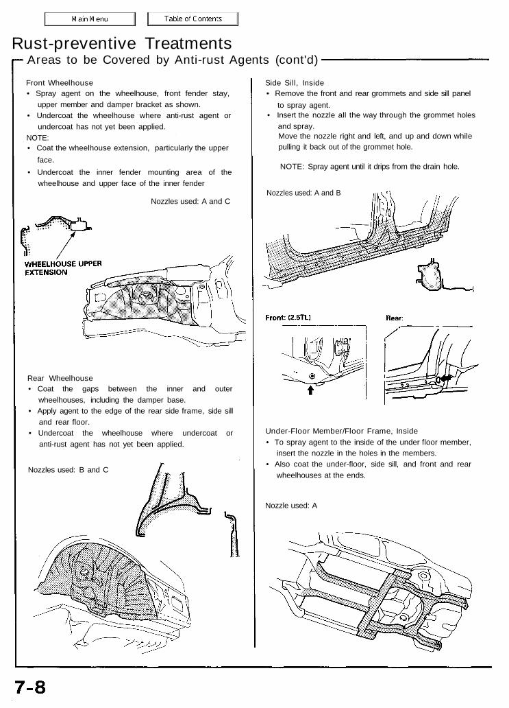
Areas to be Covered by Anti-rust Agents (cont'd)Rust-preventive Treatments
Front Wheelhouse• Spray agent on the wheelhouse, front fender stay,
upper member and damper bracket as shown.• Undercoat the wheelhouse where anti-rust agent or
undercoat has not yet been applied.NOTE:• Coat the wheelhouse extension, particularly the upper
face.• Undercoat the inner fender mounting area of the
wheelhouse and upper face of the inner fender
Nozzles used: A and C
Side Sill, Inside• Remove the front and rear grommets and side sill panel
to spray agent.• Insert the nozzle all the way through the grommet holes
and spray.Move the nozzle right and left, and up and down whilepulling it back out of the grommet hole.
NOTE: Spray agent until it drips from the drain hole.
Nozzles used: A and B
Rear Wheelhouse• Coat the gaps between the inner and outer
wheelhouses, including the damper base.• Apply agent to the edge of the rear side frame, side sill
and rear floor.• Undercoat the wheelhouse where undercoat or
anti-rust agent has not yet been applied.
Nozzles used: B and C
Under-Floor Member/Floor Frame, Inside• To spray agent to the inside of the under floor member,
insert the nozzle in the holes in the members.• Also coat the under-floor, side sill, and front and rear
wheelhouses at the ends.
Nozzle used: A
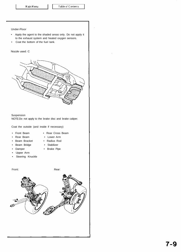
Under-Floor
• Apply the agent to the shaded areas only. Do not apply itto the exhaust system and heated oxygen sensors.
• Coat the bottom of the fuel tank.
Nozzle used: C
SuspensionNOTE:Do not apply to the brake disc and brake caliper.
Coat the outside (and inside if necessary)
• Front Beam • Rear Cross Beam• Rear Beam • Lower Arm• Beam Bracket • Radius Rod• Beam Bridge • Stabilizer• Damper • Brake Pipe• Upper Arm• Steering Knuckle
Front: Rear:

Undercoating DiagramRust-preventive Treatments
indicates PVC coating areas.
NOTE:• Coating thickness: 0.5 mm (0.02 in) MIN.• Follow the above instructions for paint repair or refinishing.• Avoid coating on the front and rear suspensions, and exhaust
system mount area.• Items marked with an asterisk (*) on the important control areas.
Coating thickness 1 mm (0.04 in).
Unit: mm (in)
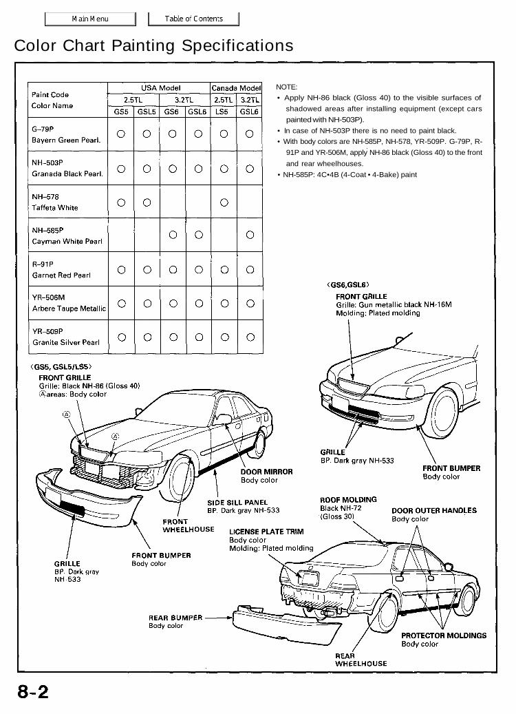
NOTE:• Apply NH-86 black (Gloss 40) to the visible surfaces of
shadowed areas after installing equipment (except carspainted with NH-503P).
• In case of NH-503P there is no need to paint black.• With body colors are NH-585P, NH-578, YR-509P. G-79P, R-
91P and YR-506M, apply NH-86 black (Gloss 40) to the frontand rear wheelhouses.
• NH-585P: 4C•4B (4-Coat • 4-Bake) paint
Color Chart Painting Specifications
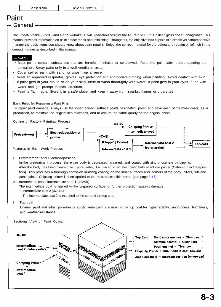
GeneralPaint
The 3-coat•3-bake (3C•3B) and 4-coat•4-bake (4C•4B) paint finishes give the Acura 2.5TL/3.2TL a deep gloss and stunning finish. Thismanual provides information on paint defect repair and refinishing. Throughout, the objective is to explain in a simple yet comprehensivemanner the basic items you should know about paint repairs. Select the correct material for the defect and repaint or refinish in thecorrect manner as described in this manual.
• Most paints contain substances that are harmful if inhaled or swallowed. Read the paint label before opening thecontainer. Spray paint only in a well ventilated area.
• Cover spilled paint with sand, or wipe it up at once.• Wear an approved respirator, gloves, eye protection and appropriate clothing when painting. Avoid contact with skin.• If paint gets in your mouth or on your skin, rinse or wash thoroughly with water. If paint gets in your eyes, flush with
water and get prompt medical attention.• Paint is flammable. Store it in a safe place, and keep it away from sparks, flames or cigarettes.
Basic Rules for Repairing a Paint FinishTo repair paint damage, always use the 2-part acrylic urethane paints designated; polish and bake each of the three coats, as inproduction, to maintain the original film thickness, and to assure the same quality as the original finish.
Outline of Factory Painting Process:
Features in Each Work Process
1. Pretreatment and ElectrodepositionIn the pretreatment process, the entire body is degreased, cleaned, and coated with zinc phosphate by dipping.After the body has been cleaned with pure water, it is placed in an electrolytic bath of soluble primer (Cationic Electrodeposi-tion). This produces a thorough corrosion inhibiting coating on the inner surfaces and corners of the body, pillars, sills andpanel joints. Chipping primer is then applied to the most susceptible areas (see page 8-16).
2. Intermediate coat / Intermediate coat 1 (4C•4B)The intermediate coat is applied to the prepared surface for further protection against damage.• Intermediate coat 2 (4C•4B)
The intermediate coat 2 is matched to the color of the top coat.
3. Top coatEnamel paint and either polyester or acrylic resin paint are used in the top coat for higher solidity, smoothness, brightness,and weather resistance.
Sectional View of Paint Coats:
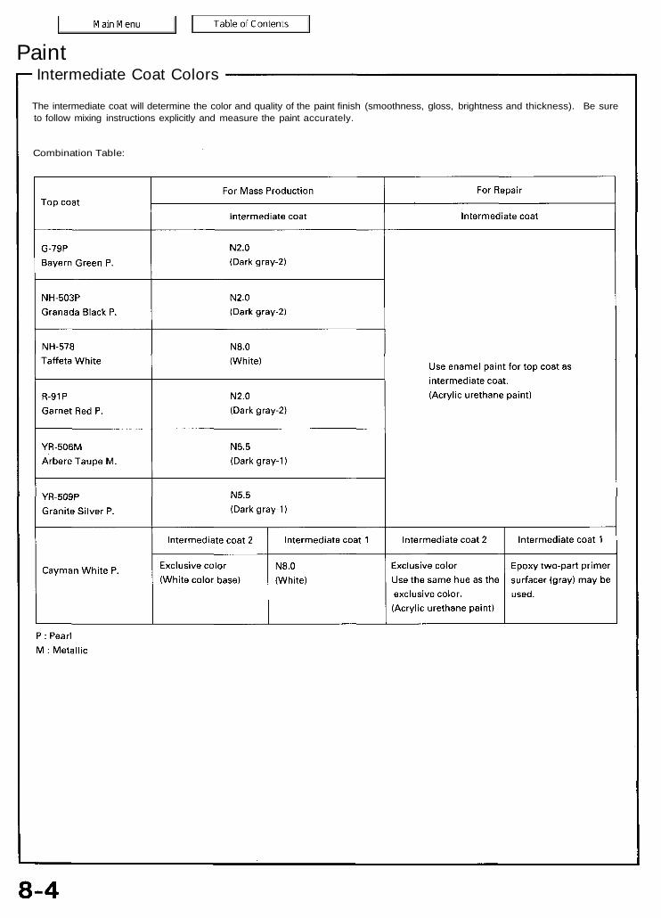
The intermediate coat will determine the color and quality of the paint finish (smoothness, gloss, brightness and thickness). Be sureto follow mixing instructions explicitly and measure the paint accurately.
Combination Table:
Intermediate Coat ColorsPaint

Paint Refinishing
Paint damage can appear in any form. Before making a repair, check the damaged area carefully, and determine the procedure bestsuited to the type. The following relates paint refinishing methods to various types of paint damage of damage or defects.
Defects and Refinishing Processes
• Ventilate when spraying paint. Most paint containssubstances that are harmful if inhaled or swallowed.Read the paint label before opening the paint contain-er.
• Avoid contact with skin. Wear an approvedrespirator, gloves, eye protection and appropriateclothing when painting.
• Paint is flammable. Store it in a safe place, and keepit away from sparks, flames or cigarettes.
A. Damage or defects that have gone through to themetal surfaceRusting or deformation:Steps:
Featheredge the damaged area.Prepare the metal surface.Apply a chemical coating to metal surface.Metal conditioner, Precoat, A.C.P treatmentApply an undercoat (primer surfacer)
NH-585P :-1 Apply intermediate coat 1 (surfacer and primer
surfacer)Apply an intermediate coat (color matched to topenamel paint).NH-585P : Intermediate coat 2
(Exclusive color paint)Apply a top coat (body color paint).Solid color: Enamel top coat paintMetallic color: Metallic enamel paint + Clear top
coatPearl color: Pearl enamel paint + Clear top coat
B. Damage or defects up to undercoat or intermediatecoat/intermediate coat 1 (NH-585P)External damage or blisters:(1) Perform Steps through under Item A.NH-585P :Damage or defects up to intermediate coat 2External damage(1) Perform steps through under Item A.
C. Damage or defects that have not gone through tointermediate coats (only in top coat)Shallow scratches or score marks:(1) If damage has gone through to the metallic paint,
spray metallic enamel, then apply top coat wet onwet.
(2) If damage has not reached the metallic color paintand remained in the clear top coat,polish the damagedsurface or spray only the clear top coat.
NOTE: Try to repair by polishing as much as possible ifthe damage has not reached the metallic color paint.
D. Replacement of Parts-1 Welded parts
Rear side outer panel, etc.(1) Perform Step through if the damaged area is
covered with filler or welded with reinforcementplate.
(2) Perform Steps and for undercoats exceptthose on joints (Intermediate coat for replacementparts).
(3) On inner panels, apply paint where the undercoat isburned by heat of welding. Follow this with a rustpreventive treatment (see section 7).
-2 Single Parts• Painting of outer and inner hood, door, trunk, lid,
etc.Perform Steps and under Item A.
• Painting of inside of front fender.Only enamel top coat paint may be used:Solid color enamel. Metallic enamel or Pearl enamel.
• After spraying enamel paint, perform rust preventivetreatment (apply inner or outer rust preventiveagent).

Refinishing ProcessesPaint
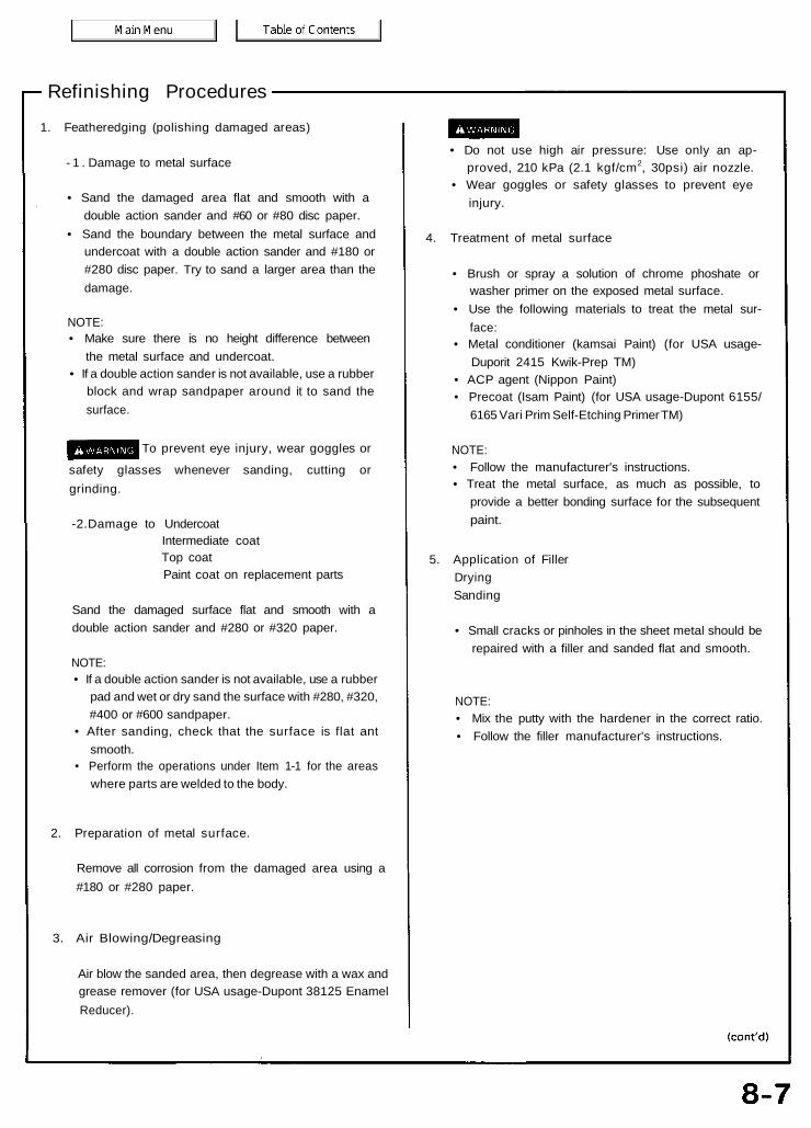
Refinishing Procedures1. Featheredging (polishing damaged areas)
- 1 . Damage to metal surface
• Sand the damaged area flat and smooth with adouble action sander and #60 or #80 disc paper.
• Sand the boundary between the metal surface andundercoat with a double action sander and #180 or#280 disc paper. Try to sand a larger area than thedamage.
NOTE:• Make sure there is no height difference between
the metal surface and undercoat.• If a double action sander is not available, use a rubber
block and wrap sandpaper around it to sand thesurface.
To prevent eye injury, wear goggles orsafety glasses whenever sanding, cutting orgrinding.
-2.Damage to UndercoatIntermediate coatTop coatPaint coat on replacement parts
Sand the damaged surface flat and smooth with adouble action sander and #280 or #320 paper.
NOTE:• If a double action sander is not available, use a rubber
pad and wet or dry sand the surface with #280, #320,#400 or #600 sandpaper.
• After sanding, check that the surface is flat antsmooth.
• Perform the operations under Item 1-1 for the areaswhere parts are welded to the body.
2. Preparation of metal surface.
Remove all corrosion from the damaged area using a#180 or #280 paper.
3. Air Blowing/Degreasing
Air blow the sanded area, then degrease with a wax andgrease remover (for USA usage-Dupont 38125 EnamelReducer).
• Do not use high air pressure: Use only an ap-proved, 210 kPa (2.1 kgf/cm2, 30psi) air nozzle.
• Wear goggles or safety glasses to prevent eyeinjury.
4. Treatment of metal surface
• Brush or spray a solution of chrome phoshate orwasher primer on the exposed metal surface.
• Use the following materials to treat the metal sur-face:
• Metal conditioner (kamsai Paint) (for USA usage-Duporit 2415 Kwik-Prep TM)
• ACP agent (Nippon Paint)• Precoat (Isam Paint) (for USA usage-Dupont 6155/
6165 Vari Prim Self-Etching Primer TM)
NOTE:• Follow the manufacturer's instructions.• Treat the metal surface, as much as possible, to
provide a better bonding surface for the subsequentpaint.
5. Application of FillerDryingSanding
• Small cracks or pinholes in the sheet metal should berepaired with a filler and sanded flat and smooth.
NOTE:• Mix the putty with the hardener in the correct ratio.• Follow the filler manufacturer's instructions.
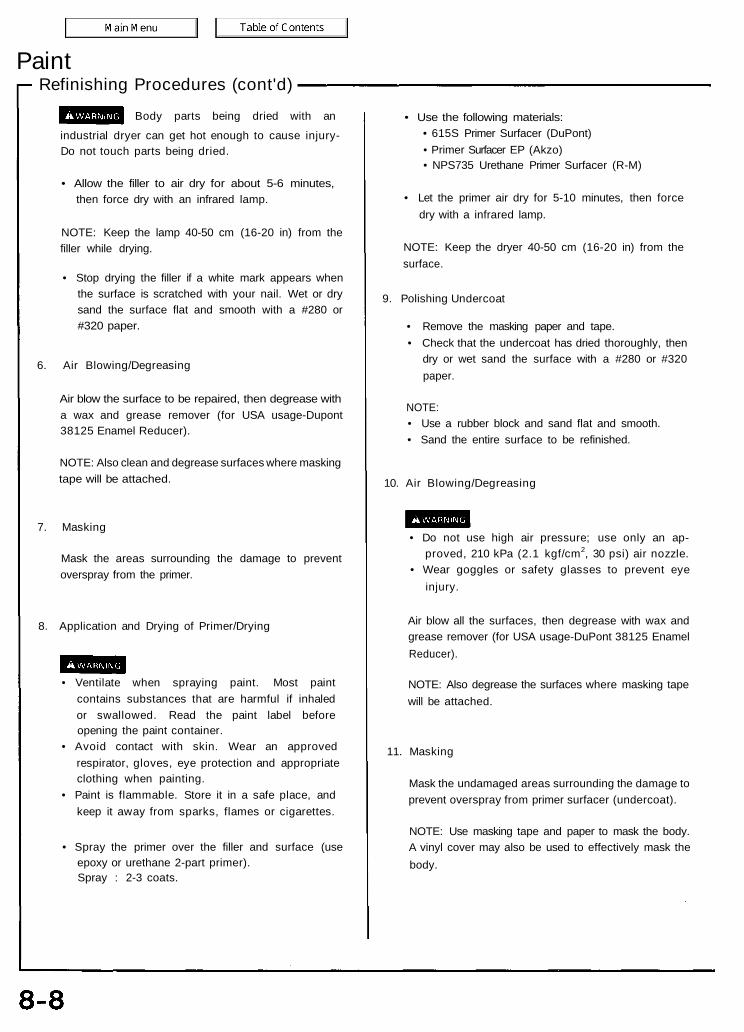
Refinishing Procedures (cont'd)Paint
Body parts being dried with anindustrial dryer can get hot enough to cause injury-Do not touch parts being dried.
• Allow the filler to air dry for about 5-6 minutes,then force dry with an infrared lamp.
NOTE: Keep the lamp 40-50 cm (16-20 in) from thefiller while drying.
• Stop drying the filler if a white mark appears whenthe surface is scratched with your nail. Wet or drysand the surface flat and smooth with a #280 or#320 paper.
6. Air Blowing/Degreasing
Air blow the surface to be repaired, then degrease witha wax and grease remover (for USA usage-Dupont38125 Enamel Reducer).
NOTE: Also clean and degrease surfaces where maskingtape will be attached.
7. Masking
Mask the areas surrounding the damage to preventoverspray from the primer.
8. Application and Drying of Primer/Drying
• Ventilate when spraying paint. Most paintcontains substances that are harmful if inhaledor swallowed. Read the paint label beforeopening the paint container.
• Avoid contact with skin. Wear an approvedrespirator, gloves, eye protection and appropriateclothing when painting.
• Paint is flammable. Store it in a safe place, andkeep it away from sparks, flames or cigarettes.
• Spray the primer over the filler and surface (useepoxy or urethane 2-part primer).Spray : 2-3 coats.
• Use the following materials:• 615S Primer Surfacer (DuPont)• Primer Surfacer EP (Akzo)• NPS735 Urethane Primer Surfacer (R-M)
• Let the primer air dry for 5-10 minutes, then forcedry with a infrared lamp.
NOTE: Keep the dryer 40-50 cm (16-20 in) from thesurface.
9. Polishing Undercoat
• Remove the masking paper and tape.• Check that the undercoat has dried thoroughly, then
dry or wet sand the surface with a #280 or #320paper.
NOTE:• Use a rubber block and sand flat and smooth.• Sand the entire surface to be refinished.
10. Air Blowing/Degreasing
• Do not use high air pressure; use only an ap-proved, 210 kPa (2.1 kgf/cm2, 30 psi) air nozzle.
• Wear goggles or safety glasses to prevent eyeinjury.
Air blow all the surfaces, then degrease with wax andgrease remover (for USA usage-DuPont 38125 EnamelReducer).
NOTE: Also degrease the surfaces where masking tapewill be attached.
11. Masking
Mask the undamaged areas surrounding the damage toprevent overspray from primer surfacer (undercoat).
NOTE: Use masking tape and paper to mask the body.A vinyl cover may also be used to effectively mask thebody.
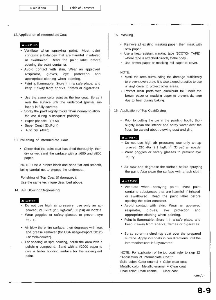
12. Application of Intermediate Coat
• Ventilate when spraying paint. Most paintcontains substances that are harmful if inhaledor swallowed. Read the paint label beforeopening the paint container.
• Avoid contact with skin. Wear an approvedrespirator, gloves, eye protection andappropriate clothing when painting.
• Paint is flammable. Store it in a safe place, andkeep it away from sparks, flames or cigarettes.
• Use the same color paint as the top coat. Spray itover the surface until the undercoat (primer sur-facer) is fully covered.
• Spray the paint slightly thicker than normal to allowfor loss during subsequent polishing.
• Super ponacle II (R-M)• Super Centri (DuPont)• Auto cryl (Akzo)
13. Polishing of Intermediate Coat
• Check that the paint coat has dried thoroughly, thendry or wet sand the surface with a #600 and #800paper.
NOTE: Use a rubber block and sand flat and smooth,being careful not to expose the undercoat.
Polishing of Top Coat (if damaged):Use the same technique described above.
14. Air Blowing/Degreasing
• Do not use high air pressure; use only an ap-proved, 210 kPa (2.1 kgf/cm2, 30 psi) air nozzle.
• Wear goggles or safety glasses to prevent eyeinjury.
• Air blow the entire surface, then degrease with waxand grease remover (for USA usage-Dupont 38125Enamel Reducer).
• For shading or spot painting, polish the area with apolishing compound. Sand with a #2000 paper togive a better bonding surface for the subsequentpaint.
15. Masking
• Remove all existing masking paper, then mask withnew paper.
• Use a heat-resistant masking tape (SCOTCH TAPE)where tape is attached directly to the body.
• Use brown paper or masking roll paper to cover.
NOTE:• Mask the area surrounding the damage sufficiently
to prevent overspray. It is also a good practice to usea vinyl cover to protect other areas.
• Protect resin parts with aluminum foil under thebrown paper or masking paper to prevent damagedue to heat during baking.
16. Application of Top Coat/Drying
• Prior to putting the car in the painting booth, thor-oughly clean the interior and spray water over thefloor. Be careful about blowing dust and dirt.
• Do not use high air pressure; use only an ap-proved, 210 kPa (2.1 kgf/cm2, 30 psi) air nozzle.
• Wear goggles or safety glasses to prevent eyeinjury.
• Air blow and degrease the surface before sprayingthe paint. Also clean the surface with a tack cloth.
• Ventilate when spraying paint. Most paintcontains substances that are harmful if inhaledor swallowed. Read the paint label beforeopening the paint container.
• Avoid contact with skin. Wear an approvedrespirator, gloves, eye protection andappropriate clothing when painting.
• Paint is flammable. Store it in a safe place, andkeep it away from sparks, flames or cigarettes.
• Spray color-matched top coat over the preparedsurface. Apply 2-3 coats in two directions until theintermediate coat is fully covered.
NOTE: For application of the top coat, refer to step 12"Application of Intermediate Coat."Solid color: Color enamel + Color clear coatMetallic color: Metallic enamel + Clear coatPearl color: Pearl enamel + Clear coat

Refinishing Procedures (cont'd)Paint
Body parts being dried with anindustrial dryer can get hot enough to cause injury.Do not touch parts being dried.
• After spraying, allow the paint to settle for about10 minutes, then force dry with an infrared lamp.
NOTE: Follow the paint manufacturer's instructions.
17. Polishing/Buffing
• Let the paint dry gradually, then polish the surfacecarefully using a polishing compound and spongebuff.
• To remove lint or dirt, wet sand the surface with#2000 paper or finer first, then polish withcompound.
NOTE: Polish all roughness caused by sanding thor-oughly. To do this, first polish with very fine com-pound, then with ultra fine compound.
• After polishing, remove the masking paper andtape, then wash the entire vehicle thoroughly.
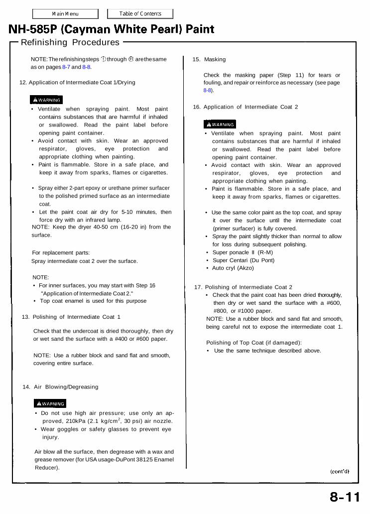
Refinishing Procedures
NOTE: The refinishing steps through are the sameas on pages 8-7 and 8-8.
12. Application of Intermediate Coat 1/Drying
• Ventilate when spraying paint. Most paintcontains substances that are harmful if inhaledor swallowed. Read the paint label beforeopening paint container.
• Avoid contact with skin. Wear an approvedrespirator, gloves, eye protection andappropriate clothing when painting.
• Paint is flammable. Store in a safe place, andkeep it away from sparks, flames or cigarettes.
• Spray either 2-part epoxy or urethane primer surfacerto the polished primed surface as an intermediatecoat.
• Let the paint coat air dry for 5-10 minutes, thenforce dry with an infrared lamp.
NOTE: Keep the dryer 40-50 cm (16-20 in) from thesurface.
For replacement parts:Spray intermediate coat 2 over the surface.
NOTE:• For inner surfaces, you may start with Step 16
"Application of Intermediate Coat 2."• Top coat enamel is used for this purpose
13. Polishing of Intermediate Coat 1
Check that the undercoat is dried thoroughly, then dryor wet sand the surface with a #400 or #600 paper.
NOTE: Use a rubber block and sand flat and smooth,covering entire surface.
14. Air Blowing/Degreasing
• Do not use high air pressure; use only an ap-proved, 210kPa (2.1 kg/cm2, 30 psi) air nozzle.
• Wear goggles or safety glasses to prevent eyeinjury.
Air blow all the surface, then degrease with a wax andgrease remover (for USA usage-DuPont 38125 EnamelReducer).
15. Masking
Check the masking paper (Step 11) for tears orfouling, and repair or reinforce as necessary (see page8-8).
16. Application of Intermediate Coat 2
• Ventilate when spraying paint. Most paintcontains substances that are harmful if inhaledor swallowed. Read the paint label beforeopening paint container.
• Avoid contact with skin. Wear an approvedrespirator, gloves, eye protection andappropriate clothing when painting.
• Paint is flammable. Store in a safe place, andkeep it away from sparks, flames or cigarettes.
• Use the same color paint as the top coat, and sprayit over the surface until the intermediate coat(primer surfacer) is fully covered.
• Spray the paint slightly thicker than normal to allowfor loss during subsequent polishing.
• Super ponacle II (R-M)• Super Centari (Du Pont)• Auto cryl (Akzo)
17. Polishing of Intermediate Coat 2• Check that the paint coat has been dried thoroughly,
then dry or wet sand the surface with a #600,#800, or #1000 paper.
NOTE: Use a rubber block and sand flat and smooth,being careful not to expose the intermediate coat 1.
Polishing of Top Coat (if damaged):• Use the same technique described above.
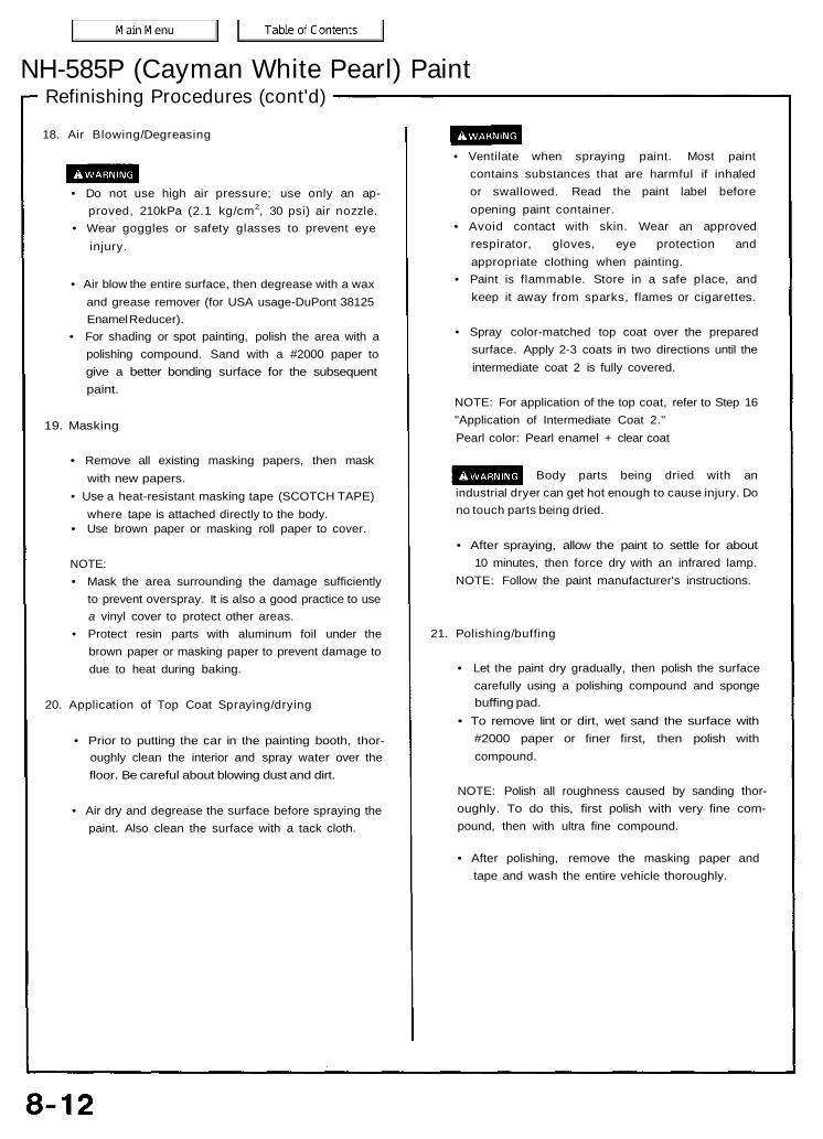
Refinishing Procedures (cont'd)NH-585P (Cayman White Pearl) Paint
18. Air Blowing/Degreasing
• Do not use high air pressure; use only an ap-proved, 210kPa (2.1 kg/cm2, 30 psi) air nozzle.
• Wear goggles or safety glasses to prevent eyeinjury.
• Air blow the entire surface, then degrease with a waxand grease remover (for USA usage-DuPont 38125Enamel Reducer).
• For shading or spot painting, polish the area with apolishing compound. Sand with a #2000 paper togive a better bonding surface for the subsequentpaint.
19. Masking
• Remove all existing masking papers, then maskwith new papers.
• Use a heat-resistant masking tape (SCOTCH TAPE)where tape is attached directly to the body.
• Use brown paper or masking roll paper to cover.
NOTE:• Mask the area surrounding the damage sufficiently
to prevent overspray. It is also a good practice to usea vinyl cover to protect other areas.
• Protect resin parts with aluminum foil under thebrown paper or masking paper to prevent damage todue to heat during baking.
20. Application of Top Coat Spraying/drying
• Prior to putting the car in the painting booth, thor-oughly clean the interior and spray water over thefloor. Be careful about blowing dust and dirt.
• Air dry and degrease the surface before spraying thepaint. Also clean the surface with a tack cloth.
• Ventilate when spraying paint. Most paintcontains substances that are harmful if inhaledor swallowed. Read the paint label beforeopening paint container.
• Avoid contact with skin. Wear an approvedrespirator, gloves, eye protection andappropriate clothing when painting.
• Paint is flammable. Store in a safe place, andkeep it away from sparks, flames or cigarettes.
• Spray color-matched top coat over the preparedsurface. Apply 2-3 coats in two directions until theintermediate coat 2 is fully covered.
NOTE: For application of the top coat, refer to Step 16"Application of Intermediate Coat 2."Pearl color: Pearl enamel + clear coat
Body parts being dried with anindustrial dryer can get hot enough to cause injury. Dono touch parts being dried.
• After spraying, allow the paint to settle for about10 minutes, then force dry with an infrared lamp.
NOTE: Follow the paint manufacturer's instructions.
21. Polishing/buffing
• Let the paint dry gradually, then polish the surfacecarefully using a polishing compound and spongebuffing pad.
• To remove lint or dirt, wet sand the surface with#2000 paper or finer first, then polish withcompound.
NOTE: Polish all roughness caused by sanding thor-oughly. To do this, first polish with very fine com-pound, then with ultra fine compound.
• After polishing, remove the masking paper andtape and wash the entire vehicle thoroughly.
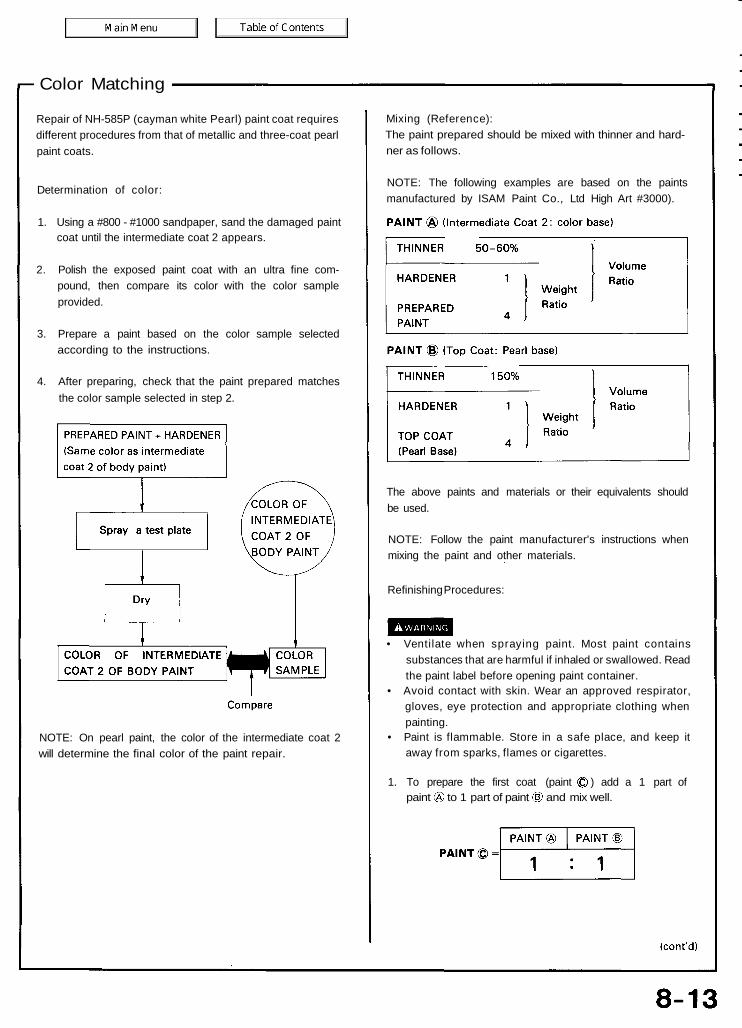
Color Matching
Repair of NH-585P (cayman white Pearl) paint coat requiresdifferent procedures from that of metallic and three-coat pearlpaint coats.
Determination of color:
1. Using a #800 - #1000 sandpaper, sand the damaged paintcoat until the intermediate coat 2 appears.
2. Polish the exposed paint coat with an ultra fine com-pound, then compare its color with the color sampleprovided.
3. Prepare a paint based on the color sample selectedaccording to the instructions.
4. After preparing, check that the paint prepared matchesthe color sample selected in step 2.
Mixing (Reference):The paint prepared should be mixed with thinner and hard-ner as follows.
NOTE: The following examples are based on the paintsmanufactured by ISAM Paint Co., Ltd High Art #3000).
The above paints and materials or their equivalents shouldbe used.
NOTE: Follow the paint manufacturer's instructions whenmixing the paint and other materials.
Refinishing Procedures:
• Ventilate when spraying paint. Most paint containssubstances that are harmful if inhaled or swallowed. Readthe paint label before opening paint container.
• Avoid contact with skin. Wear an approved respirator,gloves, eye protection and appropriate clothing whenpainting.
• Paint is flammable. Store in a safe place, and keep itaway from sparks, flames or cigarettes.
1. To prepare the first coat (paint ) add a 1 part ofpaint to 1 part of paint and mix well.
NOTE: On pearl paint, the color of the intermediate coat 2will determine the final color of the paint repair.

7. Spray 2-3 light final top coats over the damaged area.
4. Pour the mixture through a filter, then spray 2-3 lightcoats of the filtered mixture over paint Start at the center,then work toward the edge.
NOTE:• Check that the painted coat matches the color
of the body paint while spraying.• Application of the mixture will determine the final
color of the paint repair. Do not spray the mixtureexcessively as this may alter the final color of therepair.
5. Apply 1-2 light coats of paint over the repairedsurface.
6. For the final top coat, add 15% thinner to a 4 : 1mixture of the clear paint and hardener.
Color Matching (cont'd)NH-585P (Cayman White Pearl) Paint
2. Pour the mixture through a filter, then spray 2-3 lightcoats over the damaged surface.
NOTE: Spray the mixture until the intermediate coat 2is thoroughly covered.
3. Prepare paint for graduation by mixing 1 part ofPaint with 19 parts of the paint Stir the mixturewell.
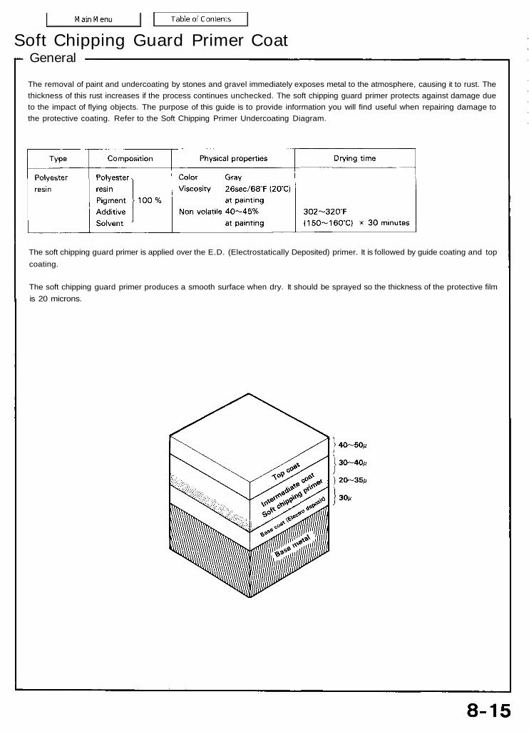
GeneralSoft Chipping Guard Primer Coat
The removal of paint and undercoating by stones and gravel immediately exposes metal to the atmosphere, causing it to rust. Thethickness of this rust increases if the process continues unchecked. The soft chipping guard primer protects against damage dueto the impact of flying objects. The purpose of this guide is to provide information you will find useful when repairing damage tothe protective coating. Refer to the Soft Chipping Primer Undercoating Diagram.
The soft chipping guard primer is applied over the E.D. (Electrostatically Deposited) primer. It is followed by guide coating and topcoating.
The soft chipping guard primer produces a smooth surface when dry. It should be sprayed so the thickness of the protective filmis 20 microns.

Coating DiagramSoft Chipping Guard Primer Coat
The diagram shows the areas to which softchipping primer is to be applied.NOTE: Make sure to coat the flange on frontand rear wheel arches.
Unit: mm (in)

Types of Soft Chipping Guard Primer (Reference)
Repair Materials and Tools
Gun and brushes:• Spray gun
NOTE: Any gun having a tip of more than 1.0 mm(0.04 in) in diameter may be used for spraying theprimer.
• Viscosity measureIwata-type (IMS) cup, Ford cup
• Beaker1-2 (1.05-2.10 US. qt, 0.9-2 Imp. qt) in capacity
• Stirring stick
Tools:• Air or double action sander• Sandpaper (#240-#400)
Thinner and cleaner:• Use the thinner specified for the primer.• Any commercially available lacquer thinner may be used
to clean the gun.
Materials:• Use primers equivalent to the ones shown in Types of
Chipping Guard Primer (Reference).• Make sure to keep the thickness of the coat at 20
microns.
Masking:• Masking tape, paper, vinyl sheet and plate (veneer and
steel).• Masking plates are not necessary when spraying in a
booth.
Protectors:• Wear an approved respirator or dust mask, gloves,
safety goggles and other protective clothing.• Rags.
• Most paints contain substances that are harmful if inhaled or swallowed. Read the paint label before opening thecontainer.
• Spray paint only in a well ventilated area.• Cover spilled paint with sand, or wipe it up at once.• Wear an approved respirator, gloves, eye protection and appropriate clothing when painting. Avoid contact with skin.• If paint gets in your mouth or on your skin, rinse or wash thoroughly with water. If paint gets in your eyes, flush with
water and get prompt medical attention.• Paint is flammable. Store it in a safe place, and keep it away from sparks, flames or cigarettes.
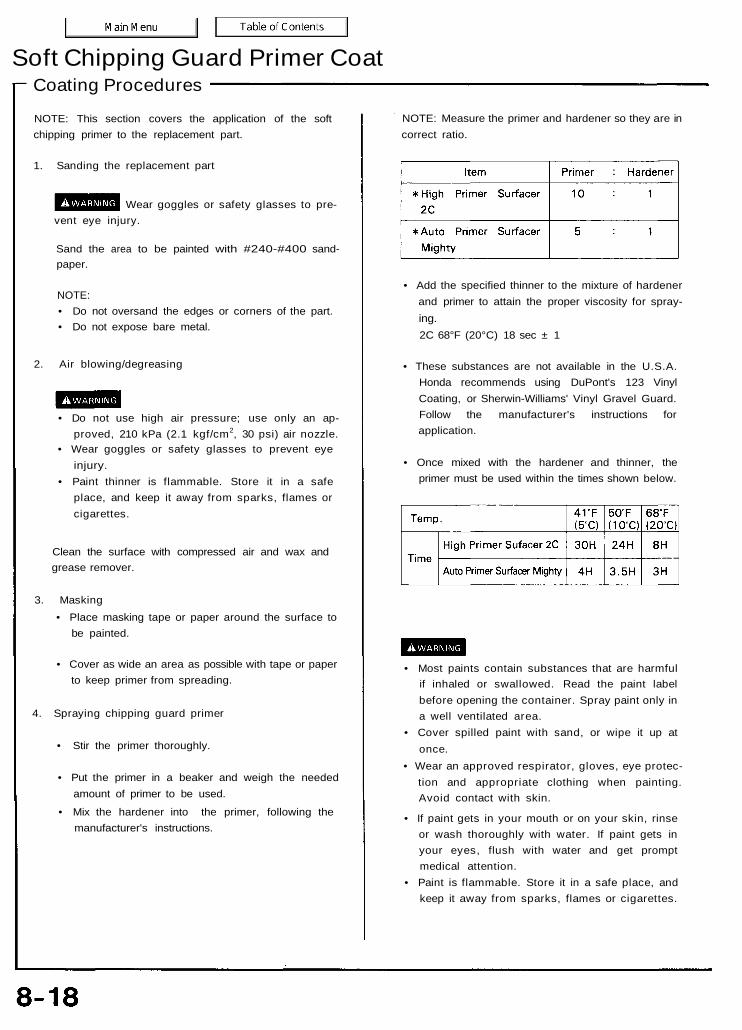
Soft Chipping Guard Primer CoatCoating Procedures
NOTE: This section covers the application of the softchipping primer to the replacement part.
1. Sanding the replacement part
Wear goggles or safety glasses to pre-vent eye injury.
Sand the area to be painted with #240-#400 sand-paper.
NOTE:• Do not oversand the edges or corners of the part.• Do not expose bare metal.
2. Air blowing/degreasing
• Do not use high air pressure; use only an ap-proved, 210 kPa (2.1 kgf/cm2, 30 psi) air nozzle.
• Wear goggles or safety glasses to prevent eyeinjury.
• Paint thinner is flammable. Store it in a safeplace, and keep it away from sparks, flames orcigarettes.
Clean the surface with compressed air and wax andgrease remover.
3. Masking• Place masking tape or paper around the surface to
be painted.
• Cover as wide an area as possible with tape or paperto keep primer from spreading.
4. Spraying chipping guard primer
• Stir the primer thoroughly.
• Put the primer in a beaker and weigh the neededamount of primer to be used.
• Mix the hardener into the primer, following themanufacturer's instructions.
NOTE: Measure the primer and hardener so they are incorrect ratio.
• Add the specified thinner to the mixture of hardenerand primer to attain the proper viscosity for spray-ing.2C 68°F (20°C) 18 sec ± 1
• These substances are not available in the U.S.A.Honda recommends using DuPont's 123 VinylCoating, or Sherwin-Williams' Vinyl Gravel Guard.Follow the manufacturer's instructions forapplication.
• Once mixed with the hardener and thinner, theprimer must be used within the times shown below.
• Most paints contain substances that are harmfulif inhaled or swallowed. Read the paint labelbefore opening the container. Spray paint only ina well ventilated area.
• Cover spilled paint with sand, or wipe it up atonce.
• Wear an approved respirator, gloves, eye protec-tion and appropriate clothing when painting.Avoid contact with skin.
• If paint gets in your mouth or on your skin, rinseor wash thoroughly with water. If paint gets inyour eyes, flush with water and get promptmedical attention.
• Paint is flammable. Store it in a safe place, andkeep it away from sparks, flames or cigarettes.
• Fill the gun's paint cup with the primer. Use astrainer when pouring the primer into the cup.
• Primer should never be applied to a dirty or greasysurface. Before spraying, blow dust and dirt off thesurface and clean with wax and grease remover.
(Method of spraying)
• Do not try to cover the surface with one heavycoat. Apply several thin coats.
NOTE:• Spray coat 4-5 coats to get 20 microns of thick-
ness, as one coat deposits 5-7 microns.• Spray the primer at 250-300 kPa (2.5-3.0 kgf/
cm2, 35.6-42.7 psi) pressure. Spraying with im-proper air pressure will cause imperfections.
• Open the gun 3-4 turns.• Wipe up unwanted primer immediately with
thinner.
5. Cleaning spray gun
• After spraying, be sure to clean the spray gunthoroughly with thinner or solvent.
• The gun will be permanently clogged if the primer isallowed to dry.
6. Drying
• After spraying the chipping guard primer, air-dry for7-10 minutes to evaporate the thinner in theprimer. Then dry it with infrared lamps at 176°F(80°C) for 30-40 minutes.
NOTE: Insufficient baking may cause pinholes if theprimer coat is too thick.
• The temperature lamps and drying timerecommendations should be followed closely.
NOTE: The upper line of time shows specifications for High Primer Surfacer 2C, and the lower line Auto Primer Surfacer Mighty.
7. Intermediate and Top coating
• Sand the chipping guard primer film with #280-#400 sandpaper.
• Follow the intermediate/top coating procedures (seepages 8-9 and 8-11).
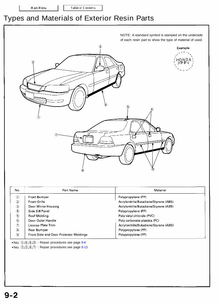
Types and Materials of Exterior Resin Parts
NOTE: A standard symbol is stamped on the undersideof each resin part to show the type of material of used.
: Repair procedures see page 9-6: Repair procedures see page 9-13
• No.• No.

GeneralPolypropylene (PP) Resin Parts
The front bumper, rear bumper, protector moldings, and side sill panel are made of polypropylene (PP) resin. They can be repaired if thedamage or deformation is minor in nature. This section covers PP repair. Repairing PP is different from other resins such as ABS andurethane.
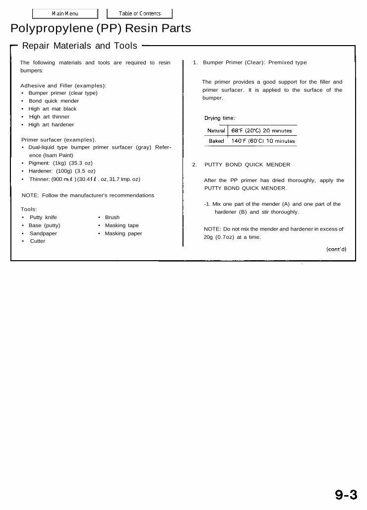
Repair Materials and ToolsThe following materials and tools are required to resinbumpers:
Adhesive and Filler (examples):• Bumper primer (clear type)• Bond quick mender• High art mat black• High art thinner• High art hardener
Primer surfacer (examples).• Dual-liquid type bumper primer surfacer (gray) Refer-
ence (Isam Paint)• Pigment: (1kg) (35.3 oz)• Hardener: (100g) (3.5 oz)• Thinner: (900 ) (30.4 . oz, 31.7 Imp. oz)
NOTE: Follow the manufacturer's recommendations
Tools:• Putty knife • Brush• Base (putty) • Masking tape• Sandpaper • Masking paper• Cutter
2. PUTTY BOND QUICK MENDER
After the PP primer has dried thoroughly, apply thePUTTY BOND QUICK MENDER.
-1. Mix one part of the mender (A) and one part of thehardener (B) and stir thoroughly.
NOTE: Do not mix the mender and hardener in excess of20g (0.7oz) at a time.
1. Bumper Primer (Clear): Premixed type
The primer provides a good support for the filler andprimer surfacer. It is applied to the surface of thebumper.
Polypropylene (PP) Resin Parts

Materials and Tools (cont'd)Polypropylene (PP) Resin Parts
-2.Hardening starts immediately after mixing.Practical hardness will be obtained within 60 min-utes. The surface will be tacky within 5 minutes andnearly hardened after 15 minutes. It takes 12 hoursfor the surface to harden thoroughly 68°F (20°C)
-3.Sanding can be done after:
• Ventilate when spraying paint. Most paintcontains substances that are harmful if inhaled orswallowed. Read the paint label before openingthe paint container.
• Avoid contact with skin. Wear an approvedrespirator, gloves, eye protection and appropriateclothing when painting.
• Paint is flammable. Store it in a safe place, andkeep it away from sparks, flames or cigarettes.
Drying time:
NOTE: The HIGH ART MAT BLACK SURFACER is adual liquid type. If mixed, it will harden in a matter ofhours.
3. Primer Surfacer
NOTE: Use a dual-liquid type bumper primer surfacer(gray).
• The primer surface is used to protect the PP resinsurface and to fill cavities or flaws in the intermediateand top coats.
• Mix 10 parts of primer surfacer and 1 part of har-dener. Add the specific thinner (30-60%) to themixture of the hardener and primer to attain theproper viscosity for spraying.
4. Intermediate and Top Paint Coats (Body color)
NOTE:• The paints are the dual liquid type based on the color
chart.• Measure the pigment and hardener as described so
they are in correct ratio.
• Use the acrylic urethane paint prepared according tothe mixing chart as the intermediate coat.
Mixing Ratio:Mix 5 parts of body color pigment to 1 part of additive.Mix 4 parts of the mixture of the pigment and additivewith 1 part of the hardener.
NOTE:• Dilute the mixture with 40-50% of the specified
thinner (Highart Thinner).• Be sure to mix the correct amount of the additive.
• Use a spray gun to apply the paint. Do not use abrush.
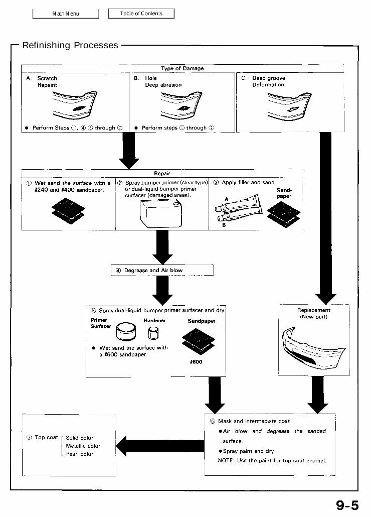
Refinishing Processes
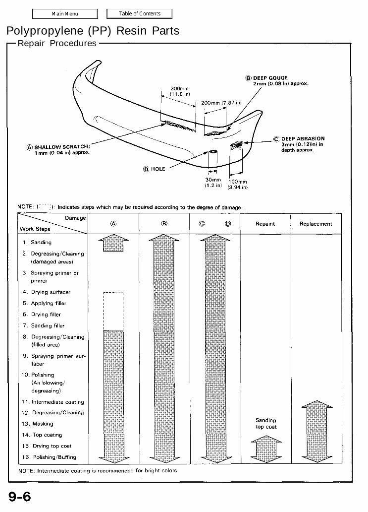
Repair ProceduresPolypropylene (PP) Resin Parts
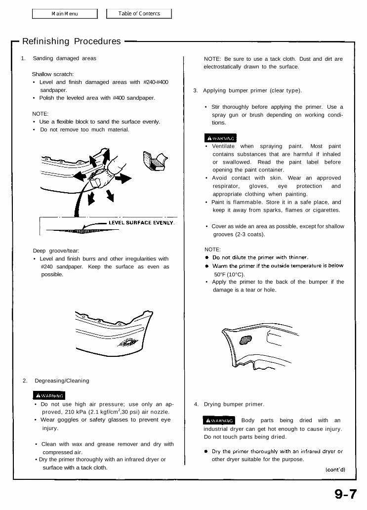
Refinishing Procedures
1. Sanding damaged areas
Shallow scratch:• Level and finish damaged areas with #240-#400
sandpaper.• Polish the leveled area with #400 sandpaper.
NOTE:• Use a flexible block to sand the surface evenly.• Do not remove too much material.
NOTE: Be sure to use a tack cloth. Dust and dirt areelectrostatically drawn to the surface.
3. Applying bumper primer (clear type).
• Stir thoroughly before applying the primer. Use aspray gun or brush depending on working condi-tions.
• Ventilate when spraying paint. Most paintcontains substances that are harmful if inhaledor swallowed. Read the paint label beforeopening the paint container.
• Avoid contact with skin. Wear an approvedrespirator, gloves, eye protection andappropriate clothing when painting.
• Paint is flammable. Store it in a safe place, andkeep it away from sparks, flames or cigarettes.
• Cover as wide an area as possible, except for shallowgrooves (2-3 coats).
NOTE:
50°F (10°C).• Apply the primer to the back of the bumper if the
damage is a tear or hole.
Deep groove/tear:• Level and finish burrs and other irregularities with
#240 sandpaper. Keep the surface as even aspossible.
2. Degreasing/Cleaning
• Do not use high air pressure; use only an ap-proved, 210 kPa (2.1 kgf/cm2,30 psi) air nozzle.
• Wear goggles or safety glasses to prevent eyeinjury.
• Clean with wax and grease remover and dry withcompressed air.
surface with a tack cloth.
4. Drying bumper primer.
Body parts being dried with anindustrial dryer can get hot enough to cause injury.Do not touch parts being dried.
• Dry the primer thoroughly with an infrared dryer or other dryer suitable for the purpose.
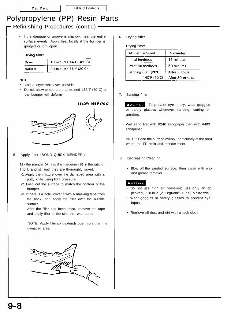
Refinishing Procedures (cont'd)Polypropylene (PP) Resin Parts
• If the damage or groove is shallow, heat the entiresurface evenly. Apply heat locally if the bumper isgouged or torn open.
NOTE:• Use a dryer whenever possible.• Do not allow temperature to exceed 158°F (70°C) or
the bumper will deform
5. Apply filler (BOND QUICK MENDER.)
Mix the mender (A) into the hardener (B) in the ratio ofI to I, and stir until they are thoroughly mixed.-1 .Apply the mixture over the damaged area with a
putty knife using light pressure.-2. Even out the surface to match the contour of the
bumper.-3. If there is a hole, cover it with a masking tape from
the back, and apply the filler over the outsidesurface.After the filler has been dried, remove the tapeand apply filler to the side that was taped.
NOTE: Apply filler so it extends over more than thedamaged area.
• Do not use high air pressure; use only an approved, 210 kPa (2.1 kgf/cm2,30 psi) air nozzle.
• Wear goggles or safety glasses to prevent eyeinjury.
• Remove all dust and dirt with a tack cloth.
7. Sanding filler
To prevent eye injury, wear gogglesor safety glasses whenever sanding, cutting orgrinding.
Wet sand first with #240 sandpaper then with #400sandpaper.
NOTE: Sand the surface evenly, particularly at the areawhere the PP resin and mender meet.
8. Degreasing/Cleaning
• Blow off the sanded surface, then clean with waxand grease remover.
6. Drying filler
Drying time:
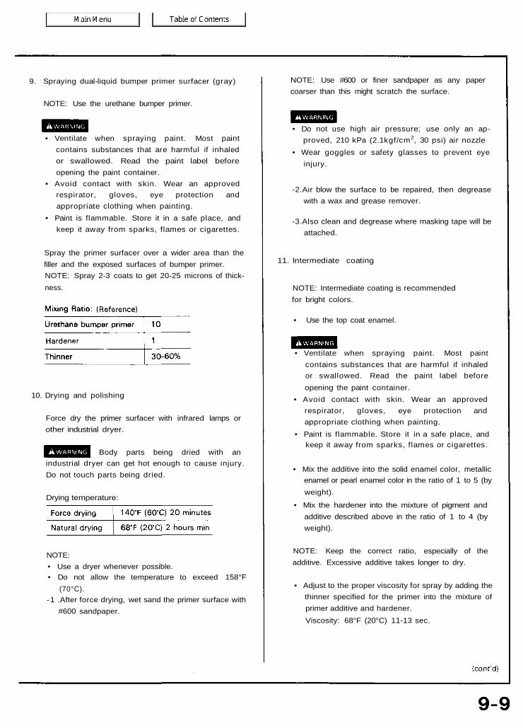
NOTE:• Use a dryer whenever possible.• Do not allow the temperature to exceed 158°F
(70°C).-1 .After force drying, wet sand the primer surface with
#600 sandpaper.
10. Drying and polishing
Force dry the primer surfacer with infrared lamps orother industrial dryer.
Body parts being dried with anindustrial dryer can get hot enough to cause injury.Do not touch parts being dried.
Drying temperature:
9. Spraying dual-liquid bumper primer surfacer (gray)
NOTE: Use the urethane bumper primer.
• Ventilate when spraying paint. Most paintcontains substances that are harmful if inhaledor swallowed. Read the paint label beforeopening the paint container.
• Avoid contact with skin. Wear an approvedrespirator, gloves, eye protection andappropriate clothing when painting.
• Paint is flammable. Store it in a safe place, andkeep it away from sparks, flames or cigarettes.
Spray the primer surfacer over a wider area than thefiller and the exposed surfaces of bumper primer.NOTE: Spray 2-3 coats to get 20-25 microns of thick-ness.
NOTE: Use #600 or finer sandpaper as any papercoarser than this might scratch the surface.
• Do not use high air pressure; use only an ap-proved, 210 kPa (2.1kgf/cm2, 30 psi) air nozzle
• Wear goggles or safety glasses to prevent eyeinjury.
-2.Air blow the surface to be repaired, then degreasewith a wax and grease remover.
-3.Also clean and degrease where masking tape will beattached.
11. Intermediate coating
NOTE: Intermediate coating is recommendedfor bright colors.
• Use the top coat enamel.
• Ventilate when spraying paint. Most paintcontains substances that are harmful if inhaledor swallowed. Read the paint label beforeopening the paint container.
• Avoid contact with skin. Wear an approvedrespirator, gloves, eye protection andappropriate clothing when painting.
• Paint is flammable. Store it in a safe place, andkeep it away from sparks, flames or cigarettes.
• Mix the additive into the solid enamel color, metallicenamel or pearl enamel color in the ratio of 1 to 5 (byweight).
• Mix the hardener into the mixture of pigment andadditive described above in the ratio of 1 to 4 (byweight).
NOTE: Keep the correct ratio, especially of theadditive. Excessive additive takes longer to dry.
• Adjust to the proper viscosity for spray by adding thethinner specified for the primer into the mixture ofprimer additive and hardener.Viscosity: 68°F (20°C) 11-13 sec.

13. Masking
• Remove all existing masking paper, then mask withnew paper.
• Use a heat resistant type masking tape (SCOTCHTAPE) where tape is attached directly to thebumper.
• Use brown paper or masking roll paper to cover.
NOTE:• Mask the area completely to prevent overspray.• Protect resin parts with aluminum foil under the
brown paper or masking paper to prevent damagedue to heat during baking.
NOTE: It is not necessary to apply the clear coat.
• Spray 2-3 coats of the top coat enamel to get 15-20microns of thickness. The primer surfacer (gray)should not show through the top coat.
NOTE:• Apply the top coat enamel to the repaired surface.• Apply the top coat enamel to the entire surface of
the primer surfacer when replacement is necessary.
12. Degreasing and Cleaning
Air dry the entire surface, then clean with wax andgrease remover (for USA usage-Dupont 38125 EnamelReducer).
NOTE: For shading or spot painting, polish the areawith a polishing compound. Also sand with a #1500paper to make a better bonding surface for the paint.
Refinishing Procedures (cont'd)Polypropylene (PP) Resin Parts
14. Top Coating
• Air dry and degrease the surface before spraying thepaint. Also clean the surface with a tack cloth.
• Ventilate when spraying paint. Most paintcontains substances that are harmful if inhaledor swallowed. Read the paint label beforeopening the paint container.
• Avoid contact with skin. Wear an approvedrespirator, gloves, eye protection andappropriate clothing when painting.
• Paint is flammable. Store it in a safe place, andkeep it away from sparks, flames or cigarettes.
• Remove dust and dirt from the surface to be coatedwith compressed air, then use a tack cloth.
• Use a strainer when filling the cup with paint.
• Spray the paint evenly over the surface so thereplacement part is completely covered.
• For application of the top coating refer to step 11" Intermediate coating."
NOTE: Do not try to cover the surface with one heavycoat. Apply several thin coats.
• With solid color (2-coat type), metallic color andpearl color enamels, allow final coat to flash-off(5-20 minutes) before applying clear coat.
• Mix the additive into the clear in the ratio of 1 to 5.Adding the hardener and adjusting viscosity shouldbe done the same way as described on the previouspage.Viscosity: 68°F (20°C) 13-15 sec.
Mixing Ratio (weight)
15. Drying top coat
Body parts being dried with anindustrial dryer can get hot enough to cause injury.Do not touch parts being dried.
• Before force drying, let it air dry for 5-10 minutes.• Force dry the sprayed surface under the infrared
lamps for 60-90 minutes.• Keep the drying temperature between 140°F (60°C)
and 158°F (70°C).
NOTE: Take care not to let the heat deform the partduring the drying process.
16. Polishing and Buffing
• Let the paint dry gradually, then polish the surfacecarefully using a polishing compound and spongebuff.
• To remove lint or dirt, wet sand the surface with#2000 or finer paper first, then polish with com-pound.
NOTE: Polish all roughness caused by sandingthoroughly. To do this, first polish with very finecompound, then with ultra fine compound.
• After polishing, remove the masking paper andtape and wash the entire vehicle thoroughly.
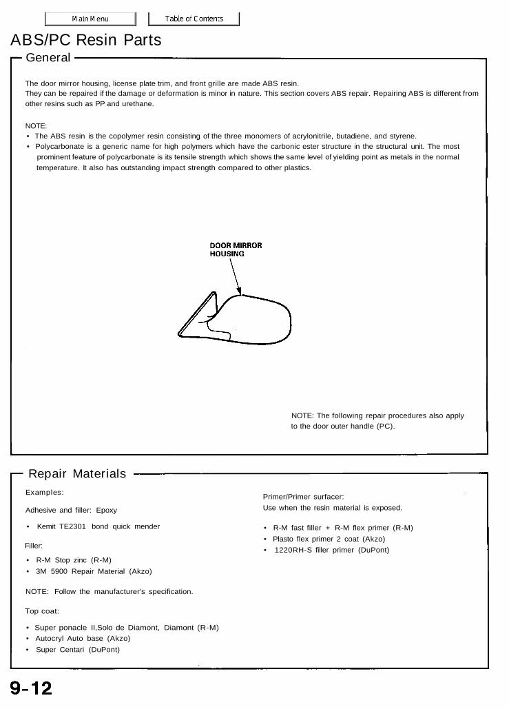
The door mirror housing, license plate trim, and front grille are made ABS resin.They can be repaired if the damage or deformation is minor in nature. This section covers ABS repair. Repairing ABS is different fromother resins such as PP and urethane.
NOTE:• The ABS resin is the copolymer resin consisting of the three monomers of acrylonitrile, butadiene, and styrene.• Polycarbonate is a generic name for high polymers which have the carbonic ester structure in the structural unit. The most
prominent feature of polycarbonate is its tensile strength which shows the same level of yielding point as metals in the normaltemperature. It also has outstanding impact strength compared to other plastics.
GeneralABS/PC Resin Parts
NOTE: The following repair procedures also applyto the door outer handle (PC).
Repair MaterialsExamples:
Adhesive and filler: Epoxy
• Kemit TE2301 bond quick mender
Filler:
• R-M Stop zinc (R-M)• 3M 5900 Repair Material (Akzo)
NOTE: Follow the manufacturer's specification.
Top coat:
• Super ponacle II,Solo de Diamont, Diamont (R-M)• Autocryl Auto base (Akzo)• Super Centari (DuPont)
Primer/Primer surfacer:Use when the resin material is exposed.
• R-M fast filler + R-M flex primer (R-M)• Plasto flex primer 2 coat (Akzo)• 1220RH-S filler primer (DuPont)
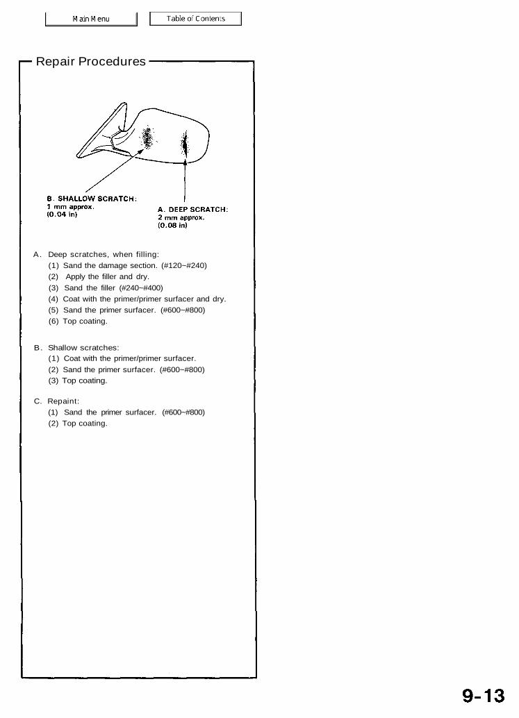
Repair Procedures
A. Deep scratches, when filling:(1) Sand the damage section. (#120~#240)(2) Apply the filler and dry.(3) Sand the filler (#240~#400)(4) Coat with the primer/primer surfacer and dry.(5) Sand the primer surfacer. (#600~#800)(6) Top coating.
B. Shallow scratches:(1) Coat with the primer/primer surfacer.(2) Sand the primer surfacer. (#600~#800)(3) Top coating.
C. Repaint:(1) Sand the primer surfacer. (#600~#800)(2) Top coating.
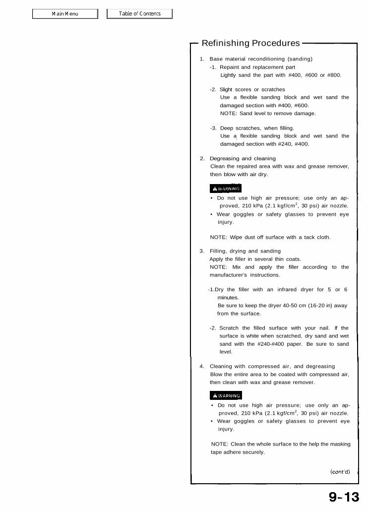
Refinishing Procedures1. Base material reconditioning (sanding)
-1. Repaint and replacement partLightly sand the part with #400, #600 or #800.
-2. Slight scores or scratchesUse a flexible sanding block and wet sand thedamaged section with #400, #600.NOTE: Sand level to remove damage.
-3. Deep scratches, when filling.Use a flexible sanding block and wet sand thedamaged section with #240, #400.
2. Degreasing and cleaningClean the repaired area with wax and grease remover,then blow with air dry.
• Do not use high air pressure; use only an ap-proved, 210 kPa (2.1 kgf/cm2, 30 psi) air nozzle.
• Wear goggles or safety glasses to prevent eyeinjury.
NOTE: Wipe dust off surface with a tack cloth.
3. Filling, drying and sandingApply the filler in several thin coats.NOTE: Mix and apply the filler according to themanufacturer's instructions.
-1.Dry the filler with an infrared dryer for 5 or 6minutes.Be sure to keep the dryer 40-50 cm (16-20 in) awayfrom the surface.
-2. Scratch the filled surface with your nail. If thesurface is white when scratched, dry sand and wetsand with the #240-#400 paper. Be sure to sandlevel.
4. Cleaning with compressed air, and degreasingBlow the entire area to be coated with compressed air,then clean with wax and grease remover.
• Do not use high air pressure; use only an ap-proved, 210 kPa (2.1 kgf/cm2, 30 psi) air nozzle.
• Wear goggles or safety glasses to prevent eyeinjury.
NOTE: Clean the whole surface to the help the maskingtape adhere securely.
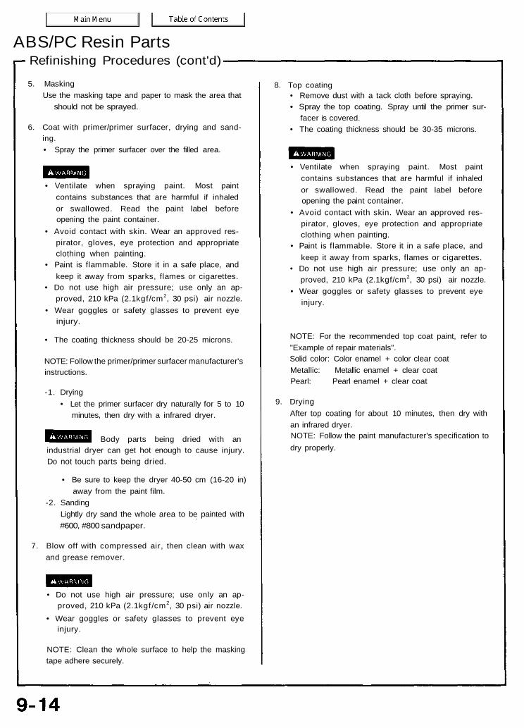
Refinishing Procedures (cont'd)ABS/PC Resin Parts
5. MaskingUse the masking tape and paper to mask the area that
should not be sprayed.
6. Coat with primer/primer surfacer, drying and sand-ing.• Spray the primer surfacer over the filled area.
• Ventilate when spraying paint. Most paintcontains substances that are harmful if inhaledor swallowed. Read the paint label beforeopening the paint container.
• Avoid contact with skin. Wear an approved res-pirator, gloves, eye protection and appropriateclothing when painting.
• Paint is flammable. Store it in a safe place, andkeep it away from sparks, flames or cigarettes.
• Do not use high air pressure; use only an ap-proved, 210 kPa (2.1kgf/cm2, 30 psi) air nozzle.
• Wear goggles or safety glasses to prevent eyeinjury.
• The coating thickness should be 20-25 microns.
NOTE: Follow the primer/primer surfacer manufacturer'sinstructions.
-1. Drying• Let the primer surfacer dry naturally for 5 to 10
minutes, then dry with a infrared dryer.
Body parts being dried with anindustrial dryer can get hot enough to cause injury.Do not touch parts being dried.
• Be sure to keep the dryer 40-50 cm (16-20 in)away from the paint film.
-2. SandingLightly dry sand the whole area to be painted with#600, #800 sandpaper.
7. Blow off with compressed air, then clean with waxand grease remover.
• Do not use high air pressure; use only an ap-proved, 210 kPa (2.1kgf/cm2, 30 psi) air nozzle.
• Wear goggles or safety glasses to prevent eyeinjury.
NOTE: Clean the whole surface to help the maskingtape adhere securely.
8. Top coating• Remove dust with a tack cloth before spraying.• Spray the top coating. Spray until the primer sur-
facer is covered.• The coating thickness should be 30-35 microns.
• Ventilate when spraying paint. Most paintcontains substances that are harmful if inhaledor swallowed. Read the paint label beforeopening the paint container.
• Avoid contact with skin. Wear an approved res-pirator, gloves, eye protection and appropriateclothing when painting.
• Paint is flammable. Store it in a safe place, andkeep it away from sparks, flames or cigarettes.
• Do not use high air pressure; use only an ap-proved, 210 kPa (2.1kgf/cm2, 30 psi) air nozzle.
• Wear goggles or safety glasses to prevent eyeinjury.
NOTE: For the recommended top coat paint, refer to"Example of repair materials".Solid color: Color enamel + color clear coatMetallic: Metallic enamel + clear coatPearl: Pearl enamel + clear coat
9. DryingAfter top coating for about 10 minutes, then dry withan infrared dryer.NOTE: Follow the paint manufacturer's specification todry properly.
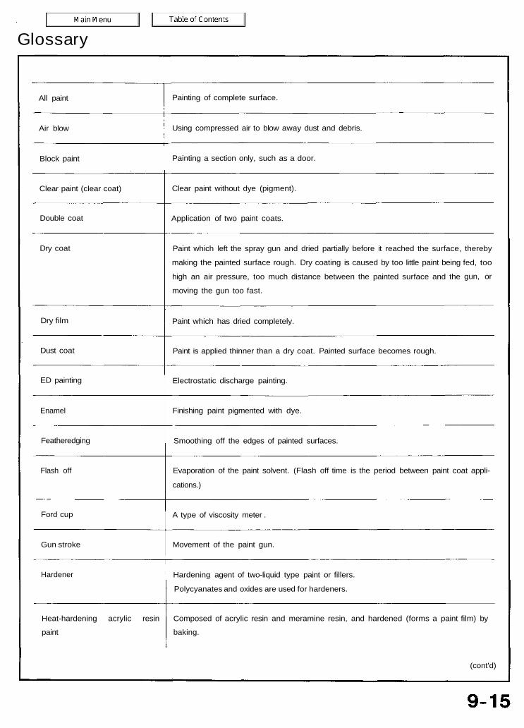
Glossary
All paint
Air blow
Block paint
Clear paint (clear coat)
Double coat
Dry coat
Dry film
Dust coat
ED painting
Enamel
Featheredging
Flash off
Ford cup
Gun stroke
Hardener
Heat-hardening acrylic resin
paint
Painting of complete surface.
Using compressed air to blow away dust and debris.
Painting a section only, such as a door.
Clear paint without dye (pigment).
Application of two paint coats.
Paint which left the spray gun and dried partially before it reached the surface,
making the painted surface rough. Dry coating is caused by too little paint being
high an air pressure, too much distance between the painted surface and the
moving the gun too fast.
thereby
fed, too
gun, or
Paint which has dried completely.
Paint is applied thinner than a dry coat. Painted surface becomes rough.
Electrostatic discharge painting.
Finishing paint pigmented with dye.
Smoothing off the edges of painted surfaces.
Evaporation of the paint solvent. (Flash off time is the period between paint coat appli-
cations.)
A type of viscosity meter .
Movement of the paint gun.
Hardening agent of two-liquid type paint or fillers.
Polycyanates and oxides are used for hardeners.
Composed of acrylic resin and meramine resin, and hardened (forms a paint film) by
baking.
(cont'd)
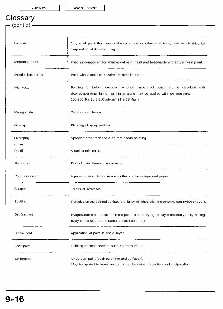
Glossary(cont'd)
Lacquer
Meramine resin
Metallic-base paint
Mist coat
Mixing scale
Overlap
Overspray
Paddle
Paint dust
Paper dispenser
Scrapes
Scuffing
Set (setting)
Single coat
Spot paint
Undercoat
A type of paint that uses cellulose nitrate or other chemicals, and which
evaporation of its solvent agent.
dries by
Used as component for aminoalkyd resin paint and heat-hardening acrylic resin paint.
Paint with aluminum powder for metallic tone.
Painting for fade-in sections. A small amount of paint may be dissolved with
slow-evaporating thinner, or thinner alone may be applied with low pressure.
150-200kPa (1.5-2. 0kgf/cm2,21.3-28. 4psi)
Color mixing device.
Blending of spray patterns.
Spraying other than the area that needs painting.
A tool to mix paint.
Dust of paint formed by spraying.
A paper posting device (masker) that combines tape and paper.
Traces of scratches.
Particles on the painted surface are lightly polished with fine emery paper (#600 or over).
Evaporation time of solvent in the paint, before drying the layer forcefully or
(May be considered the same as flash-off time.)
by baking.
Application of paint in single layer.
Painting of small section, such as for touch-up.
Undercoat paint (such as primer and surfacer).
May be applied to lower section of car for noise prevention and rustproof ing.
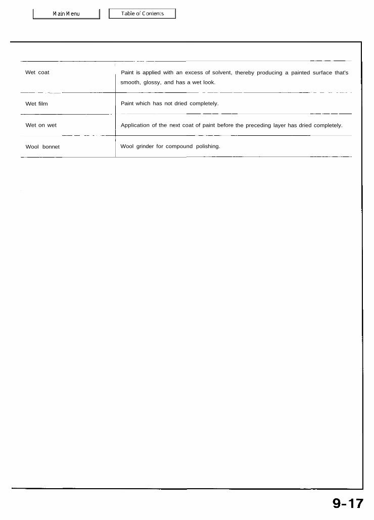
Wet coat
Wet film
Wet on wet
Wool bonnet
Paint is applied with an excess of solvent,
smooth, glossy, and has a wet look.
thereby producing a painted surface that's
Paint which has not dried completely.
Application of the next coat of paint before the preceding layer has dried completely.
Wool grinder for compound polishing.
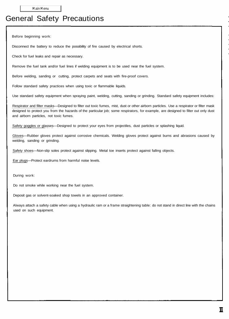
General Safety Precautions
Before beginning work:
Disconnect the battery to reduce the possibility of fire caused by electrical shorts.
Check for fuel leaks and repair as necessary.
Remove the fuel tank and/or fuel lines if welding equipment is to be used near the fuel system.
Before welding, sanding or cutting, protect carpets and seats with fire-proof covers.
Follow standard safety practices when using toxic or flammable liquids.
Use standard safety equipment when spraying paint, welding, cutting, sanding or grinding. Standard safety equipment includes:
Respirator and filter masks—Designed to filter out toxic fumes, mist, dust or other airborn particles. Use a respirator or filter maskdesigned to protect you from the hazards of the particular job; some respirators, for example, are designed to filter out only dustand airborn particles, not toxic fumes.
Safety goggles or glasses—Designed to protect your eyes from projectiles, dust particles or splashing liquid.
Gloves—Rubber gloves protect against corrosive chemicals. Welding gloves protect against burns and abrasions caused bywelding, sanding or grinding.
Safety shoes—Non-slip soles protect against slipping. Metal toe inserts protect against falling objects.
Ear plugs—Protect eardrums from harmful noise levels.
During work:
Do not smoke while working near the fuel system.
Deposit gas or solvent-soaked shop towels in an approved container.
Always attach a safety cable when using a hydraulic ram or a frame straightening table: do not stand in direct line with the chainsused on such equipment.
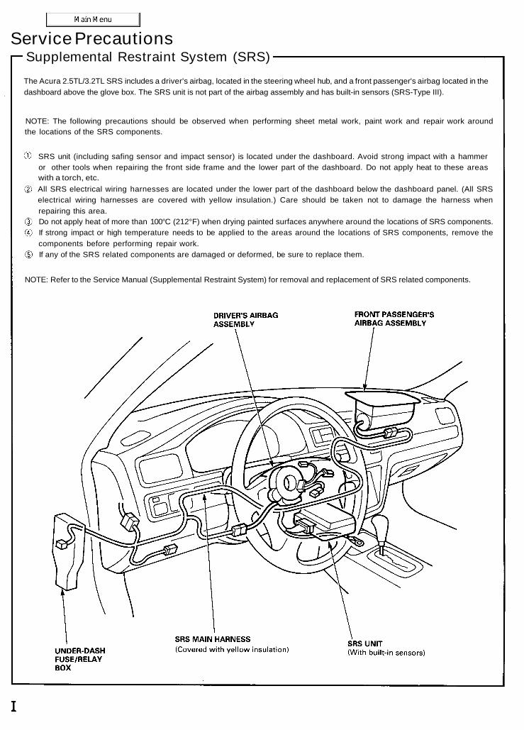
Service PrecautionsSupplemental Restraint System (SRS)
The Acura 2.5TL/3.2TL SRS includes a driver's airbag, located in the steering wheel hub, and a front passenger's airbag located in thedashboard above the glove box. The SRS unit is not part of the airbag assembly and has built-in sensors (SRS-Type III).
NOTE: The following precautions should be observed when performing sheet metal work, paint work and repair work aroundthe locations of the SRS components.
SRS unit (including safing sensor and impact sensor) is located under the dashboard. Avoid strong impact with a hammeror other tools when repairing the front side frame and the lower part of the dashboard. Do not apply heat to these areaswith a torch, etc.All SRS electrical wiring harnesses are located under the lower part of the dashboard below the dashboard panel. (All SRSelectrical wiring harnesses are covered with yellow insulation.) Care should be taken not to damage the harness whenrepairing this area.Do not apply heat of more than 100°C (212°F) when drying painted surfaces anywhere around the locations of SRS components.If strong impact or high temperature needs to be applied to the areas around the locations of SRS components, remove thecomponents before performing repair work.If any of the SRS related components are damaged or deformed, be sure to replace them.
NOTE: Refer to the Service Manual (Supplemental Restraint System) for removal and replacement of SRS related components.


