Actuation and Control systems for Petrochemical process ... · reliability during normal and...
22
Actuation and Control systems for Petrochemical process valves Best practice and new trends Alberto Pedrini IMI REMOSA Actuation and Controls Engineering Manager
Transcript of Actuation and Control systems for Petrochemical process ... · reliability during normal and...

Actuation and Control systems for Petrochemical process valvesBest practice and new trends
Alberto PedriniIMI REMOSA
Actuation and Controls Engineering Manager

2
HPCU
Actuator
Process Valve
‣ HPCU provides accurate valve positioning control for process through hydraulic valve directed by a control system.
‣ The system should provide full redundancy of the most critical items and functionalities in order to guarantee high
reliability during normal and emergency operation
Actuating system for process valve

3
Hydraulic Units description
‣ HPCU: Hydraulic Power Control Unit
‣ Power
‣ HPU transforms electric energy supplied to pump motors, into the
hydraulic pressure needed for valve operation. Furthermore, it ensures oil
cleanliness and temperature control
‣ Control
‣ Hydraulic power (pressurized oil) is stored in the accumulators, and
directed to the hydraulic cylinder to change the slide valve disc position.
This position can be changed automatically (DCS and PLC control system)
or manually by the field operator.

4
‣ HPCU: Block Diagram
Hydraulic unit description

5
PLC cabinet
HPCU layoutCurrent state – integrated HPCU
HPU+HCUPLC cabinet/EJBs
HPU
HCU
Especially old installations are
based on integrated layout
Each valve has its own control
system, HPU and HCU
Advantages
‣ Commissioning
‣ Logistics
Disadvantages
‣ Ex-proof installation (Exd Exp)
‣ Dimension of HPCU
‣ Limited Choices

6
HPUInstalled on ground or
with HCU
HCUInstalled on platform
PLC cabinet rackInstalled in safe area
HPCU layoutAlternative and new trends – Splitted HPCU
New installation prefers to have control system splitted to hydraulics and installed in safe area
This solution is applied especially when a package with more than 4 valve is provided
Disadvantages
‣ Commissioning
‣ Logistics
Advantages
‣ No Ex-proof
‣ Dimension of HPCU
‣ Numerous Choices

7
Control system – From Old to New Technology
Available Features:
‣ Valve positioning control
‣ Monitoring HPCU by means of analog transmitters and digital switches
‣ Management of main equipment (pumps, reservoir, accumulators)
‣ Generating alarms
‣ High performance valve positioning control and advanced system
management
‣ Providing user with detailed informations about HPCU status
‣ Dealing with faults and abnormal events by actively adjusting HPCU
operation in real time
‣ Touch screen HMI
‣ Increased diagnostics and remote assistance
An
alo
g c
on
tro
ller
PL
C

8
PLC vs analog controller
PLC System key features (vs analog controller)‣ Performance
‣ Easy reprogramming and updating of software to provide system upgrade or
optimization
‣ Interchangeability (simple spares procurement) and scalability
‣ Easy Maintenance and Troubleshooting
‣ Low Power Consumption
‣ Small physical size
‣ Several Communication Options
‣ Human Machine Interface
‣ Communication module to remotely monitor HPCU status!
PLC has
become a MUST
for HPCU
control system

9
HPU – Current technology
Purposes‣ Stores the hydraulic fluid and protects it against contamination particles and moisture
‣ Pressurizes the oil to be used in the HCU for valve positioning / ESD
‣ Controls the oil temperature
Main Elements:
Oil Reservoir Pressure pumps
Variable displ. type Filter-PSV
manifold
Cooling&Recirc. system

10
Increase the system pressureIn the past normal hydraulic pressure was 100-120 barg.
E.g. Some licensors still require system pressure <125barg in its specs
HPU – Alternative and new trends
System pressure can be increased up to 160 bar without any negative impact and with
the following benefits:
• Smaller cylinder (means small flow rate)
• Smaller components in general (servo, accumulators, valves, etc)
• HPCU are smaller and more standardized
11
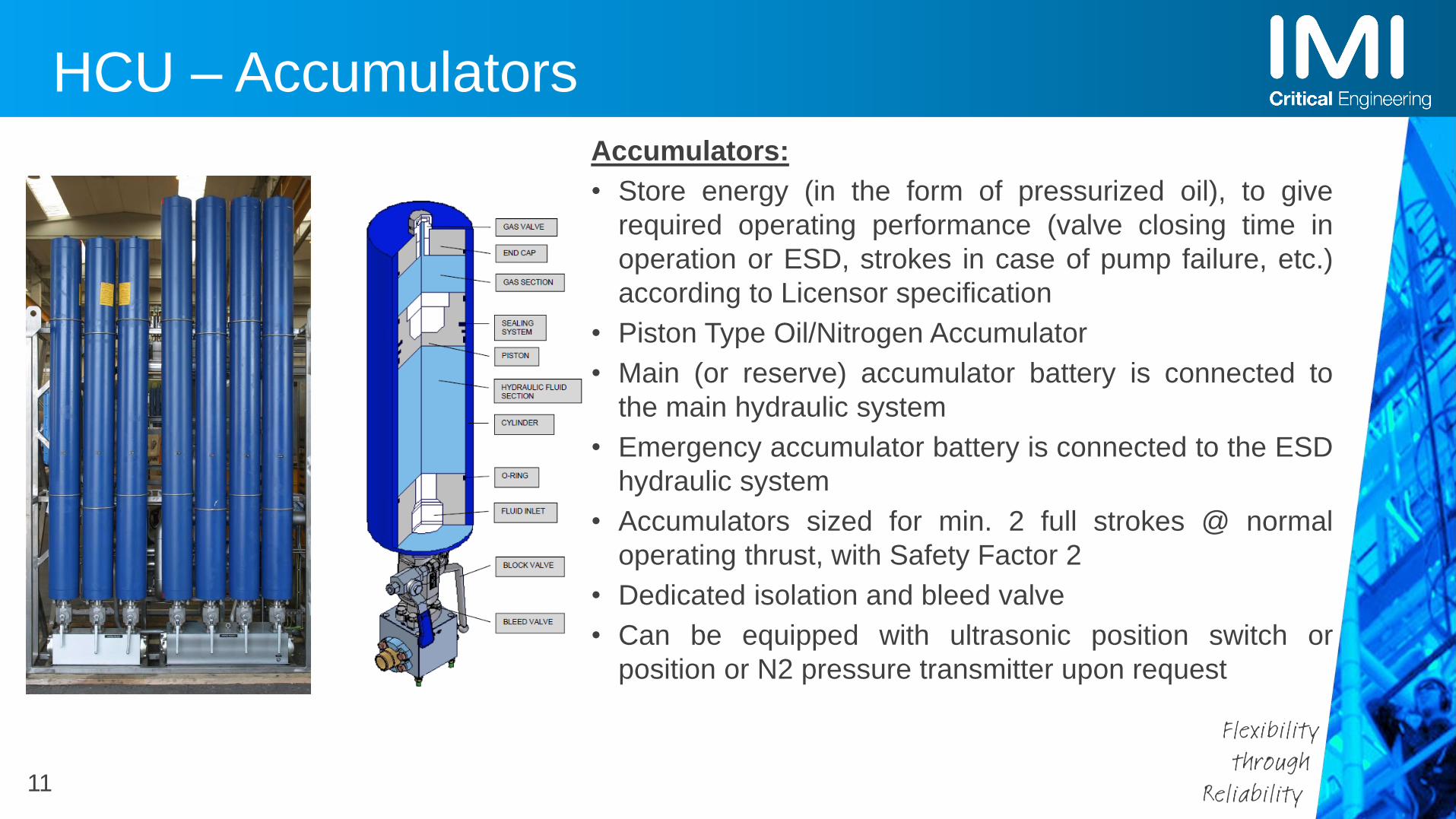
HCU – Accumulators
Accumulators:
• Store energy (in the form of pressurized oil), to give
required operating performance (valve closing time in
operation or ESD, strokes in case of pump failure, etc.)
according to Licensor specification
• Piston Type Oil/Nitrogen Accumulator
• Main (or reserve) accumulator battery is connected to
the main hydraulic system
• Emergency accumulator battery is connected to the ESD
hydraulic system
• Accumulators sized for min. 2 full strokes @ normal
operating thrust, with Safety Factor 2
• Dedicated isolation and bleed valve
• Can be equipped with ultrasonic position switch or
position or N2 pressure transmitter upon request

12
HCU – Manifolds
Control Manifold
‣ The “heart” of the HPCU, transforming the electrical command into oil flow
regulation to the actuator
‣ The control is provided by a servovalve
‣ Manual Operator 3-Position Valve (Open-Auto-Close)
‣ Solenoid Valve for lock in position and energy saving mode
ESD Manifold
‣ Solenoid operated, fail to close, ESD action.
‣ Solenoid valve poppet type. possible configuration in 1oo1, 1oo2, 2oo2, 2oo4
‣ SOV powered by Emergency Interlock System or independent power source
‣ Manual ESD Test Valve
‣ Design ESD closing time is normally less than 2 secs for SV
Cylinder I/F manifold
‣ Provide interface connection to the actuator cylinder
‣ Equipped with block and bleed of the main cylinder hydraulic line

13
Servovalve vs Proportional Valve
HCU – Alternative and new trends
The spool is hydraulically piloted by a jet pipe or similar
Existing from 1940s
Zero overlap
Response time < 18ms
Max current 300mA
Hysteresis 0.5-3%
High sensibility to oil contamination
Solenoid is used to provide infinite positioning of the spool
It is required dedicated electronics to drive the solenoid
Positive overlap
Response time < 60ms
Max current 2.5 A
Hysteresis < 5%
Less sensibility to oil contamtination
There is no clear distinction between servovalve and proportional valve. Different vendors tend to give different definition
Are you asking if proportional valves are suitable for FCC control valve application? The answer is yes!

14
Actuator – Current Technology
Linear Actuator
Rotary Actuator
Slide valve and butterfly valve are equipped respectively with linear and rotary actuator.
IMI Remosa designs and manufactures several sizes of actuator in order to meet the most stringent
customer performance requirements

15
LINEAR ACTUATOR
Position switch Redundant Position transmitters
Hydraulic piston
Emergency handwheel
Position indicator
Handwheel engagement lever
Actuator – Current Technology

16
Actuator – New trends
Although hydraulics is still the best solution for providing high force at high speed,
the technology of electrical cylinder is growing fast.
Main concerns remain:
‣ Force vs speed
‣ Accumulation method for emergency function (big batteries needed!)
‣ High current to be provided very close to the FCC valve
Servo-motorLead screw

17
1) Fluid Cleanliness **
✓ HPCU Malfunctioning
✓ Limited functionality of the HPCU
✓ Shortened lifetime of Equipment
2) Component Malfunctioning
✓ HPCU Malfunctioning
3) No OEM Spare Parts on Stock
4) Hydraulic Leakage
✓ HPCU Malfunctioning
✓ Fire Risk
5) Erosion Corrosion
✓ HPCU Malfunctioning
✓ Fire Risk
6) Other
Actuation & Control Systems - Common Issues
Oil Not Clean25%
Component Malfunctioning
21%
No Spare Parts19%
Leakages13%
Erosion / Corrosion
12%
Other10%
IMI Remosa Statistics of last 5 Years (based on Customer Emergency Field Service calls)
** fluid cleanliness level of ISO 17/14/11, 85% of all types of hydraulic system failures are a direct consequence of fluidcontamination.

18
Control Systems - Common Issues
No Spare Parts on Stock in Refinery
Defective / Worn Out of HPCU Equipment & Hoses/Pipes
Hydraulic Leakages

19
Defective / Worn Out Equipment
Before After

20
5) Erosions & Corrosions
Before After
«Cilinder Bellow», a Special Solution for Severe Service

21
Typical maintenance schedule
PERIODIC CHECK DESCRIPTION FREQUENCY
Visual inspection for major leaks Every month
Start for 1 minute the back-up main pump to verify functionality Every month
Start for 1-minute back-up recirculation pump to verify functionality Every month
Start for 1-minute back-up heater to verify functionality Every month
Verify accumulator nitrogen pre-charge pressure.
(This check shall be performed isolating one accumulator from the other in order to
maintain the system in operation)
Every 3 months or every TA
(whatever occurs before)
Replace oil tank breather When silica gel become “pink”
Replace filter (high pressure, return line, recirculation line) Every TA or with “High” alarm for filter differential
pressure
(whatever occurs before)
Hydraulic oil analysis Every 2 months or when new oil is introduced in the
system
(whatever occurs before)
Replace all Flexible hoses Every TA or 4 years
(whatever occurs before)
Replace hydraulic system O-rings When leakage occurs
Or every TA
Or every 4 years
(whatever occurs before)
Replace solenoids, control valve Every 2 TA or 10 years (whatever occurs before)

Thank You!