Activity 3.1.3 Basic Inputs Programming –...
18
Activity 3.1.3 Basic Inputs Programming – VEX Introduction Inputs are devices which provide a processor with environmental information to make decisions. These devices have the capacity to sense the environment in a variety of ways such as physical touch, rotation, and light. An engineer can design a system to respond to its environment through the use of input sensors. In this activity you will use ROBOTC and VEX robotics platform components to sense the environment. Equipment Computer with ROBOTC software POE VEX ® testbed PLTW ROBOTC template Procedure 1. Form groups of four and acquire your group’s POE VEX Kit under your teacher’s direction. 2. Within your four student group, form a two student team known as Team A and a two student team known as Team B. a. Team A will use the VEX Testbed without the ultrasonic and the light sensor. Project Lead The Way, Inc. Copyright 2011 POE – Unit 3 – Activity 3.1.3 Basic Inputs Programming – VEX – Page 1
-
Upload
nguyenthien -
Category
Documents
-
view
214 -
download
0
Transcript of Activity 3.1.3 Basic Inputs Programming –...
Activity 3.1.3 Basic Inputs Programming – VEXIntroduction
Inputs are devices which provide a processor with environmental information to make decisions. These devices have the capacity to sense the environment in a variety of ways such as physical touch, rotation, and light. An engineer can design a system to respond to its environment through the use of input sensors. In this activity you will use ROBOTC and VEX robotics platform components to sense the environment.
Equipment Computer with ROBOTC software POE VEX® testbed PLTW ROBOTC template
Procedure1. Form groups of four and acquire your group’s POE VEX Kit under your teacher’s
direction.
2. Within your four student group, form a two student team known as Team A and a two student team known as Team B.
a. Team A will use the VEX Testbed without the ultrasonic and the light sensor.
b. Team B will use the VEX Testbed without the servo motor and flashlight.
c. At the appropriate time, both teams will exchange testbeds.
3. Connect the POE VEX testbed Cortex to the PC.
Project Lead The Way, Inc.
Copyright 2011
POE – Unit 3 – Activity 3.1.3 Basic Inputs Programming – VEX – Page 1

POE VEX Testbed
Project Lead The Way, Inc.
Copyright 2011
POE – Unit 3 – Activity 3.1.3 Basic Inputs Programming – VEX – Page 2
Parts 1 and 2: Using the Bump Switch 4. Open the PLTW ROBOTC template. Click File, Save As, select the folder that
your teacher designated for you to save your ROBOTC programs in, then name the file A3_1_3_Part1.
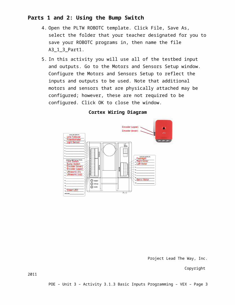
5. In this activity you will use all of the testbed input and outputs. Go to the Motors and Sensors Setup window. Configure the Motors and Sensors Setup to reflect the inputs and outputs to be used. Note that additional motors and sensors that are physically attached may be configured; however, these are not required to be configured. Click OK to close the window.
Cortex Wiring Diagram
Project Lead The Way, Inc.
Copyright 2011
POE – Unit 3 – Activity 3.1.3 Basic Inputs Programming – VEX – Page 3

6. Copy and paste or create the program below in the task main() section of the program between the curly braces.
untilBump(bumpSwitch);
startMotor(rightMotor, 67);
Project Lead The Way, Inc.
Copyright 2011
POE – Unit 3 – Activity 3.1.3 Basic Inputs Programming – VEX – Page 4
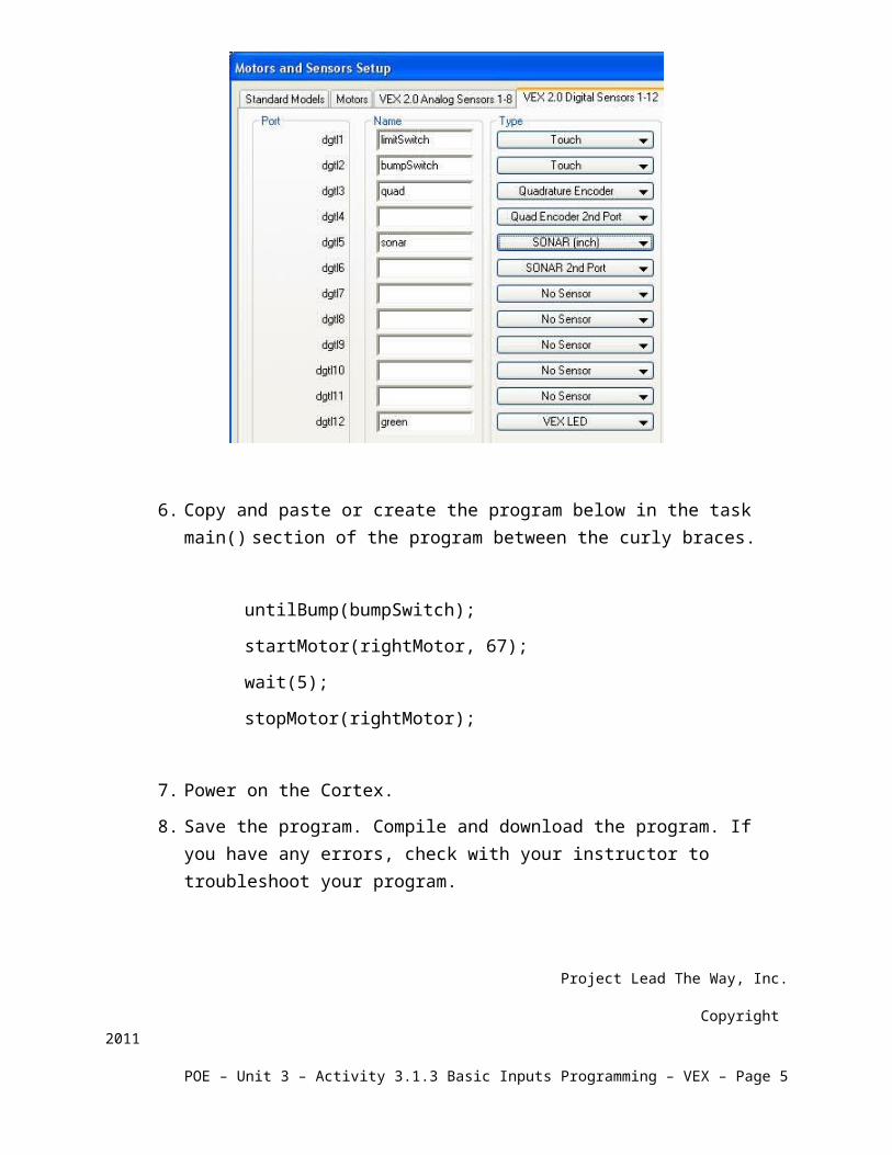
wait(5);
stopMotor(rightMotor);
7. Power on the Cortex.
8. Save the program. Compile and download the program. If you have any errors, check with your instructor to troubleshoot your program.
9. Press Start to run the program and observe the behaviors.
10.Document what this program would look like as pseudocode simple behaviors.
Project Lead The Way, Inc.
Copyright 2011
POE – Unit 3 – Activity 3.1.3 Basic Inputs Programming – VEX – Page 5

11.Open the PLTW ROBOTC template. Click File, Save As, select the folder that your teacher designated, then name the file A3_1_3_Part2.
12.The wiring configuration and motors and sensors tabs should be the same as above.
Project Lead The Way, Inc.
Copyright 2011
POE – Unit 3 – Activity 3.1.3 Basic Inputs Programming – VEX – Page 6

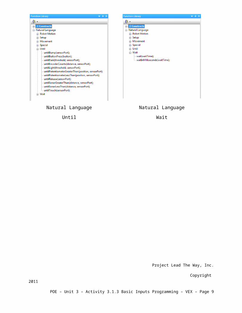
13.Write a program that performs the following simple behaviors. Use the natural language functions where appropriate as shown below. Add comments at the end of each command line to explain the purpose of each step.
a. Wait for the bumper switch to be bumped. Note that bump means that a switch is pressed and released and not simply pressed and held.
b. Both motors turn on at half power until the sensor is bumped again.
c. Both motors should then move in reverse at half power for 3.5 seconds.
d. Both motors will stop.
Natural Language
Movement
Natural Language
Special
Project Lead The Way, Inc.
Copyright 2011
POE – Unit 3 – Activity 3.1.3 Basic Inputs Programming – VEX – Page 7

Natural Language
Until
Natural Language
Wait
Project Lead The Way, Inc.
Copyright 2011
POE – Unit 3 – Activity 3.1.3 Basic Inputs Programming – VEX – Page 8
14.Test the program and troubleshoot if needed until the expected behavior has occurred. Save the program.
Part 3: Using the Potentiometer15.Open the PLTW ROBOTC template. Click File, Save As, select the folder that
your teacher designated, then name the file A3_1_3_Part3.
16.The wiring configuration and motors and sensors tabs should be the same as above.
17.Copy and paste or create the program below in the task main() section of the program between the curly braces.
turnLEDOn(green);
untilPotentiometerGreaterThan(2048, potentiometer);
turnLEDOff(green);
startMotor(leftMotor, 63);
wait(3.5);
stopMotor(leftMotor);
18.Download and run the program. Observe the behaviors and document what this program would look like as pseudocode simple behaviors.
19.Modify your program to perform the pseudocode below.
a. Verify that the potentiometer is at a value of less than 2048.
b. Turn on the greenLED until the potentiometer value is greater than 2048.
c. Turn off the greenLED.
d. Turn on the leftMotor at half power until the potentiometer is less than 2048.
Project Lead The Way, Inc.
Copyright 2011
POE – Unit 3 – Activity 3.1.3 Basic Inputs Programming – VEX – Page 9
e. Turn leftMotor off.
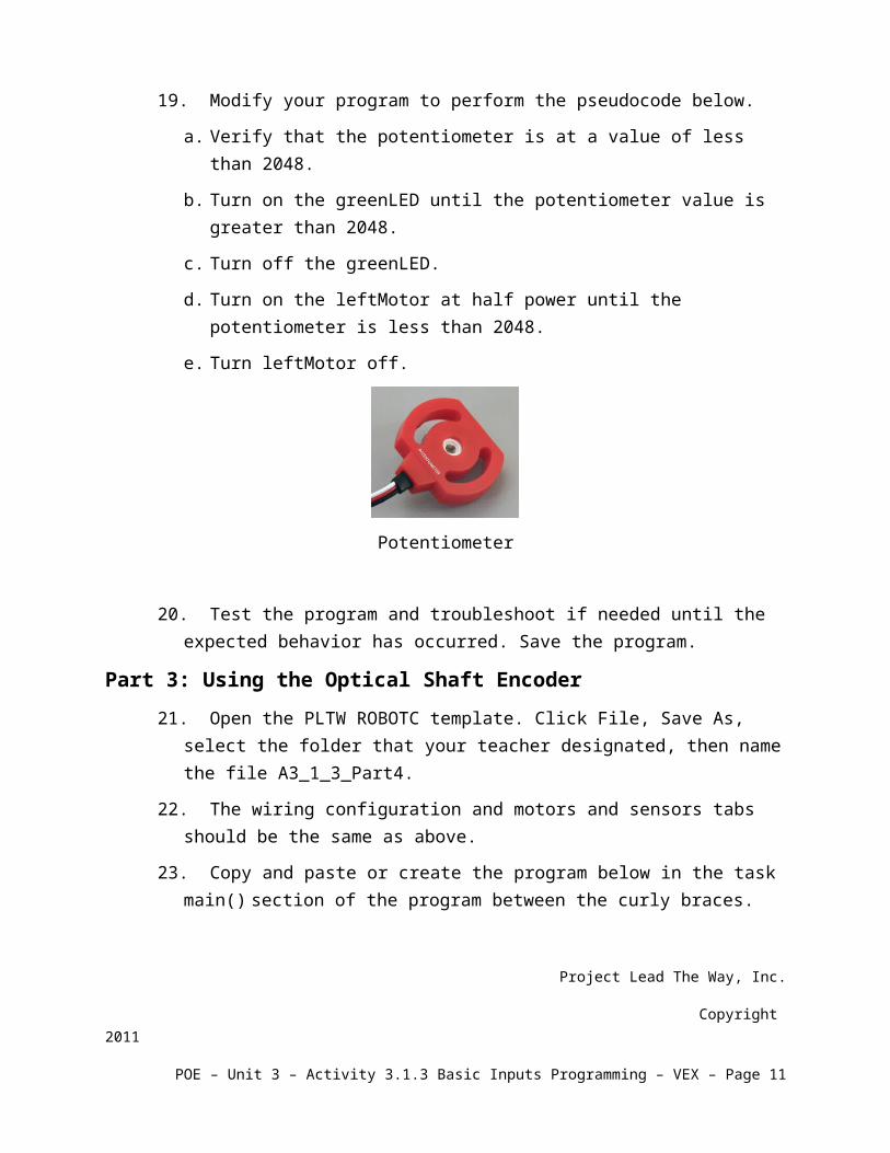
Potentiometer
20.Test the program and troubleshoot if needed until the expected behavior has occurred. Save the program.
Part 3: Using the Optical Shaft Encoder21.Open the PLTW ROBOTC template. Click File, Save As, select the folder that
your teacher designated, then name the file A3_1_3_Part4.
22.The wiring configuration and motors and sensors tabs should be the same as above.
23.Copy and paste or create the program below in the task main() section of the program between the curly braces.
startMotor(leftMotor, 63);
startMotor(rightMotor, 63);
untilEncoderCounts(480,quad);
stopMotor(leftMotor);
stopMotor(rightMotor);
24.Download and run the program. Observe the behaviors and document what this program would look like as pseudocode simple behaviors.
25.Modify your program to perform the pseudocode below.
Project Lead The Way, Inc.
Copyright 2011
POE – Unit 3 – Activity 3.1.3 Basic Inputs Programming – VEX – Page 10
a. Turn on both motors forward until the encoder has counted 480 degrees
b. Turn on both motors in reverse until another 3.5 rotations of the encoder have passed
c. Turn off both motors
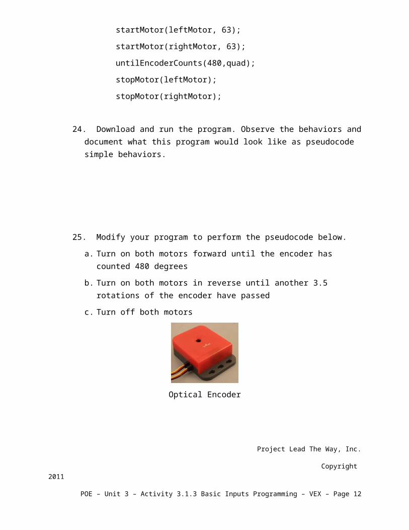
Optical Encoder
26.Test the program and troubleshoot until the expected behavior has occurred. Save the program.
Part 5: Using the Infrared Line Follower27.Open the PLTW ROBOTC template. Click File, Save As, select the folder that
your teacher designated, then name the file A3_1_3_Part5.
28.The wiring configuration and motors and sensors tabs should be the same as above.
29.Set the line follower threshold. Thresholds allow your robot to make decisions via Boolean Comparisons
a. Calculate an appropriate threshold with the aid of the Sensor Debug Window.
b. Open the Sensor Debug Window
Project Lead The Way, Inc.
Copyright 2011
POE – Unit 3 – Activity 3.1.3 Basic Inputs Programming – VEX – Page 11
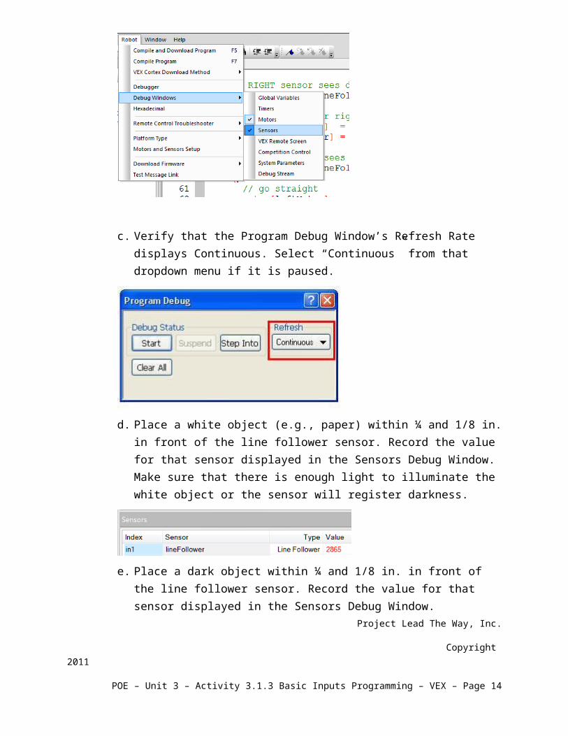
c. Verify that the Program Debug Window’s Refresh Rate displays Continuous. Select “Continuous” from that dropdown menu if it is paused.
d. Place a white object (e.g., paper) within ¼ and 1/8 in. in front of the line follower sensor. Record the value for that sensor displayed in the Sensors Debug Window. Make sure that there is enough light to illuminate the white object or the sensor will register darkness.
e. Place a dark object within ¼ and 1/8 in. in front of the line follower sensor. Record the value for that sensor displayed in the Sensors Debug Window.
f. Add the two values and divide by two. The result is the threshold for that sensor.
30.Copy and paste or create the program below in the task main() section of the program between the curly braces.
Project Lead The Way, Inc.
Copyright 2011
POE – Unit 3 – Activity 3.1.3 Basic Inputs Programming – VEX – Page 12

setServo(servoMotor, 127);
untilLight(1425, lineFollower);
setServo(servoMotor, -127);
31.Download and run the program. Observe the behaviors and document what this program would look like as pseudocode simple behaviors.
32.Modify your program to perform the pseudocode below.
a. Move the servo to position 127 until a dark object is detected
b. Move servo to position -127
Line Follower
33.Test the program and troubleshoot until the expected behavior has occurred. Save the program.
34.Teams prepare to share testbeds. Team A will install one ultrasonic sensor on the testbed. Team A completes the following steps related to the ultrasonic sensor then exchanges testbeds with team B. Team B completes steps associated with the ultrasonic sensor.
Part 6: Using the Ultrasonic Distance Sensor35.Open the PLTW ROBOTC template. Click File, Save As, select the folder that
your teacher designated, then name the file A3_1_3_Part6.
36.The wiring configuration and motors and sensors tabs should be the same as above.
Project Lead The Way, Inc.
Copyright 2011
POE – Unit 3 – Activity 3.1.3 Basic Inputs Programming – VEX – Page 13
37.Copy and paste or create the program below in the task main() section of the program between the curly braces.
startMotor(leftMotor, 63);
startMotor(rightMotor, 63);
untilSonarLessThan(20, sonar);
stopMotor(leftMotor);
stopMotor(rightMotor);
turnLEDOn(green);
wait(6.25);
turnLEDOff(green);
38.Download and run the program. Observe the behaviors and document what this program would look like as pseudocode simple behaviors.
39.Modify your program to perform the pseudocode below.
a. Wait until an object is detected within 20 cm to turn both motors on.
b. Wait for the object to move more than 25 cm away before turning the motors off.
Ultrasonic
40.Test the program and troubleshoot until the expected behavior has occurred. Save the program.
Project Lead The Way, Inc.
Copyright 2011
POE – Unit 3 – Activity 3.1.3 Basic Inputs Programming – VEX – Page 14

41.Exchange testbeds. Team B will complete the ultrasonic steps.
42.Follow teacher direction and either print the programs or submit electronically with this activity.
Project Lead The Way, Inc.
Copyright 2011
POE – Unit 3 – Activity 3.1.3 Basic Inputs Programming – VEX – Page 15

Conclusion1. Describe any challenges that you encountered while developing the program.
2. Describe three applications for the use of sensors that you worked with in this activity.
Project Lead The Way, Inc.
Copyright 2011
POE – Unit 3 – Activity 3.1.3 Basic Inputs Programming – VEX – Page 16