Activities in Cigré in the Field of Surge Arresters - an...
55
1 SC A3 High Voltage Equipment WG A3.17 / WG A3.25 October 16 th 2012, San Diego, US Activities in Cigré in the Field of Surge Arresters - an overview - Bernhard Richter (Switzerland)
Transcript of Activities in Cigré in the Field of Surge Arresters - an...

1
SC A3 High Voltage EquipmentWG A3.17 / WG A3.25October 16th 2012, San Diego, US
Activities in Cigré in the Field of Surge Arresters
- an overview -
Bernhard Richter (Switzerland)

2
A3.17Evaluation of stresses of Surge Arresters and appropriate test procedures
First meeting: October 2003 in Darmstadt / GermanyLast meeting: August 2008 in Paris / France(in total 11 meetings)20 members (15/5) representing 13 countries
A3.25MO varistors and surge arresters for emerging system conditions
First meeting: August 2009 in Stellenbosch /South AfricaNext meeting: March 2013 in Beatenberg / Switzerland22 members (18/4) representing 10 countries
3
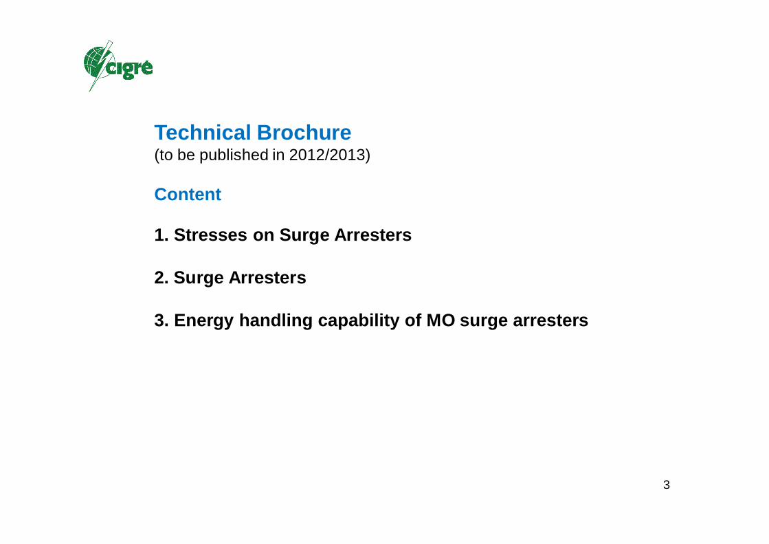
Technical Brochure (to be published in 2012/2013)
Content
1. Stresses on Surge Arresters
2. Surge Arresters
3. Energy handling capability of MO surge arresters
4
1.Stresses on Surge Arresters- Stresses from three phase systems
- Stresses from HVDC networks
- Stresses in traction systems
- Stresses from lightning
- Stresses from ambiance

5
Stresses from the power system network- temporary overvoltages with power frequency (TOV)
=> mainly a problem in medium voltage systems
- voltage increase due to load rejection
- switching overvoltages
Voltage stresses generated in the system can be calculated if the system parameters and characteristics of the circuit breakers etc. are known (mostly worst case scenarios).

6
Example: TOV in a MV system with isolated star point
Symmetric load
Earth fault in phase L3

7
HVDC networks
The voltage waveforms in HVDC networks require other dimensioning rules for the continuous voltage and some specific tests on the MO arresters (e.g. the accelerated ageing procedure).

8
Lightning stresses- lightning categories
- summer and winter lightning
Lightning overvoltages and the energy content of a surge depend on the lightning current only and are pure statistically.
But only a fraction of the lightning current will stress the MO arrester, depending on the system voltage and line configuration.

9
Lightning categories (acc. Berger)
Negative
downwards
Positive
downwards
Positive
upwards
Negative
upwards

10
Annual number of days with thunderstorms
Source: Martyn D., Climates of the World, Elsevier, Amsterdam, 1992

11
Probability of lightning currents
Statistical evaluation of lightning measurements all over the world. Described is the probability of occurrence above the lightning currents‘ peak value.

12
Winter lightningJapan as well as Norway and some other countries experience rather often thunderstorms during winter. Typical weather conditions to create the winter thunderstorms are strong winds from the west which bring rather warm air from the ocean to the mountains of the main land.
Example of a positive lightning current in a winter lightning at Fukui in Japan in February 1983. Winter lightning flashes have typically one discharge only, but with a very high charge lowered to earth.

13
In low voltage (LV) and medium voltage (MV) power systems (0,23 kV Us 52 kV) distribution lines are generally of lower height and less exposed to direct flashes than transmission lines. Most of the occurring overvoltages are due to induced voltages coming from lightning to or in surrounding structures.
High voltage (HV) systems in the range of 52 kV < Us 245 kV consist both of distribution and transmission lines which pass through rural areas. Direct strokes, back flashovers and induced voltages will statistically result in a higher stress for the installed arresters than in other voltage systems.
Transmission lines in extra high voltage (EHV) with 245 kV < Us 800 kV and ultra high voltage (UHV) systems above 800 kV have steel towers with shield wires and are in spite of their height above ground well protected against direct lightning strokes to the phase wires. Only shielding failures and back flashovers will cause a critical surge in the phase wire.

14
Stresses from ambiance
Ambient stresses can be very different in the different regions of the world.
Very cold climates with ice and snow load have to be considered as well as climates with high temperature and high relative humidity.
Mechanical stresses like seismic loads influence strongly the structure and materials used for the design of the MO arresters. Vibrations as well as static loads have to be considered and appropriate test procedures have been developed accordingly.
Observations of biological growth on the surface of polymer insulation have been made worldwide. Three types of organic growth have been identified: Algae, Fungi and Lichen. Despite all the reports of biological growth on the insulation in some areas of the world there are no known failures of MO arresters caused by it.

15
107
012
Hokkaido
116
025
Tohoku
205
432
Kanto
93
37
Chubu
17 13
Hokuriku
95
117
Kansai
13 01
Chugoku
13 01
Chugoku
58
04
Kyushu
Sismic intensity scale[Acceleration (Gal)][25-80] [80-250] [250-400]
Seismic records in the past 75 years from 1921 to 1995 in Japan
Seismic test of GIS arrester, horizontal
installation
16
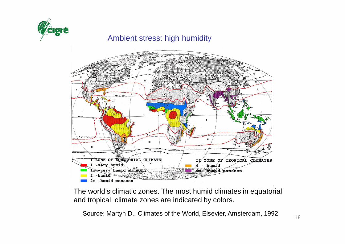
The world’s climatic zones. The most humid climates in equatorial and tropical climate zones are indicated by colors.
Ambient stress: high humidity
Source: Martyn D., Climates of the World, Elsevier, Amsterdam, 1992
17
0102030405060708090
100
0 100 200 300 400 500 600 700 800
Testing Time (days)
Leak
age
Cur
rent
(A
) Group IGroup IIGroup III
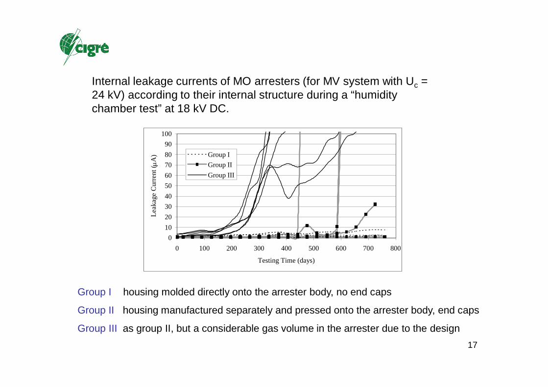
Internal leakage currents of MO arresters (for MV system with Uc = 24 kV) according to their internal structure during a “humidity chamber test” at 18 kV DC.
Group I housing molded directly onto the arrester body, no end caps
Group II housing manufactured separately and pressed onto the arrester body, end caps
Group III as group II, but a considerable gas volume in the arrester due to the design

18
0
50
100
150
200
250
300
0 20 40 60 80 100 120 140
Testing time (days)
Leak
age
curr
ent (
nA)
Type AType B
Change of leakage current due to diffusion and recovery
Type X
Type Y

19
3
2
1
Risk of "internal"partial discharges,degradation of theMO resistors anddeterioration of thesupporting structure
Risk of partial heating of the activeparts (see Annex F of IEC 60099-4)
Risk of externalflashover (seeIEC 60507)
33
22
11
Risk of "internal"partial discharges,degradation of theMO resistors anddeterioration of thesupporting structure
Risk of partial heating of the activeparts (see Annex F of IEC 60099-4)
Risk of externalflashover (seeIEC 60507)
Possible risks due to pollution
MO column
Conductivelayer
Gas
Solid
Uax
ial,
int
Uradial
MO column
Conductivelayer
Gas
Solid
Uax
ial,
int
Uradial
Possible voltage distributions of an arrester unit under polluted condition
Ambient stress: pollution of the arrester housing

20
Ambient stress: biological growth (examples)

21
Ambient stresses: animal attack

22
2. Surge Arresters- Function and relevant parameters
- MO-Varistors: state of the art and actual trends
- Design of surge arresters
- Special designs of surge arresters
- SF6 gas insulated MO surge arresters
- Integrated arrester systems
23
Function and design of MO arresters
MO arresters have basically two parts:
- the active part => stack of MO resistors => electrical characteristic
- the housing, providing insulation and mechanical support

24
Insulation co-ordination
Main criteria for selecting MO surge arresters:
Protection level Upl and maximum continuous operating voltage Uc
Energy capability W and highest temporary overvoltage UTOV
Economic and safety margin aspects

25
A Pre-breakdown region B Breakdown region C Upturn region1 DC voltage characteristic 2 AC voltage characteristic 3 Residual voltage characteristicE Field strength J Current density UG Continuous operating voltage (DC)UB Breakdown (or switching) voltageUv Continuous operating voltage (50 Hz)Up Residual voltage at In
Resistivity Non-linearity exponent (U)
Log-log plot of the normalized E-J
characteristic of a typical MO resistor

26
Fracture surface,2000 times enlarged
Electron microscope image of the MO structure
Schematic view of the structureA: ZnO-crystalB: triple point, phase Bi2O3C: mono atomic layer of O- and Bi-atomsD: electrical active grain boundary
(voltage controlled “switch”)

27
Band diagram scheme of the hole induced breakdown mechanism

28
0
0.2
0.4
0.6
0.8
1
1.2
0 100 200 300 400 500 600 700 800 900 1000
time [h]
pow
er lo
ss ra
tio P
/ Po
stable
unstable
0
0.2
0.4
0.6
0.8
1
1.2
1.4
0 100 200 300 400 500 600 700 800 900 1000
time [h]
pow
er lo
ss ra
tio P
/ Po
stable varistor in air or N2unstable varistor in airunstable varistor in N2
Long term performance of MO resistors
Power loss ratio vs. time for stable and unstable MO resistors during accelerated ageing tests at 115 °C and slightly elevated AC operating voltage.left: AC stress only right: influence of the surrounding medium

29
MO Surge Arrester Design – Polymer Housed
Due to their simple internal structure, MO arresters were amongst the first apparatuses in electrical power systems equipped with polymerhousings:
• Mid 1980s – first polymer housed distribution arresters
• End 1980s – first polymer housed high-voltage arresters
In the meantime, three basic design principles have emerged:
• "tube" design
• "wrapped" design
• "cage" design
30
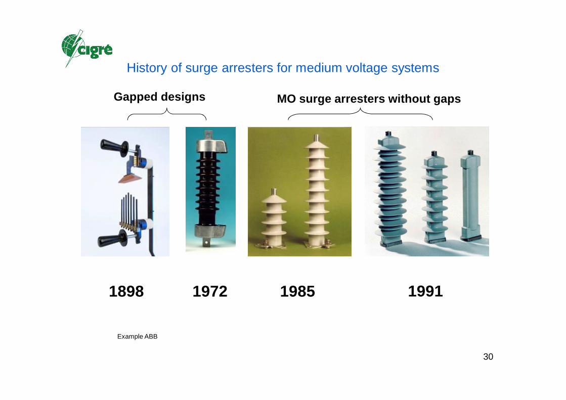
History of surge arresters for medium voltage systems
1898 19911972 1985
Gapped designs MO surge arresters without gaps
Example ABB

31
MO Surge Arrester Design – Porcelain Housed
Compression spring
MO column
Pressure relief vent
Porcelain housing
Pressure relief diaphragm
O-ring
Sulfur cement bonding
Supporting rod (FRP)
Fixing plate (FRP)
Aluminum flange
Example: Siemens
Insulating base

32
Polymer Housed – "Tube" Design
Examples: Siemens
Porcelain housedPorcelain housed Polymer housedPolymer housed
33
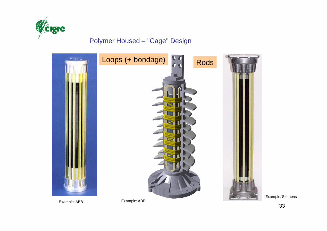
Polymer Housed – "Cage" Design
Loops (+ bondage)Loops (+ bondage)
Example: ABB
RodsRods
Example: SiemensExample: ABB

34
Progress in arrester designHV arresters station class for Us = 145 kV
Left: SiC arrester with gaps and porcelain housing (about 40 years ago)
Right: completely molded MO arrester without gaps
Both arresters have the same ratings.
Example ABB

35
HV: Uc = 174 kV
MV: Uc = 44 kV
Tertiary winding: Uc = 18 kV
HV substation 245 kV
Example ABB, Switzerland
36
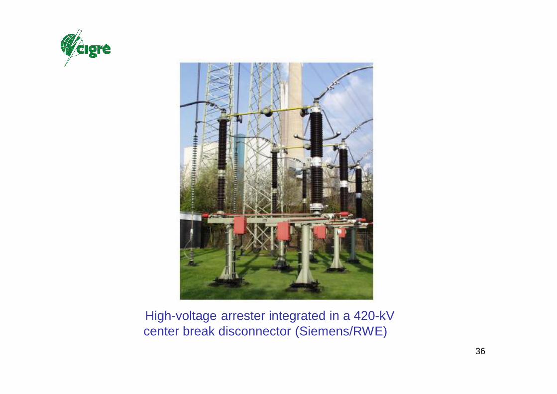
High-voltage arrester integrated in a 420-kV center break disconnector (Siemens/RWE)

37
Polymer housed arresters serving as post insulators:EnBW/Germany (left), Powerlink /Australia (right)
38
3. Energy handling capability of MO surge arresters
- The different aspects of “energy handling capability”
- State of the knowledge about energy handling of MO arresters
- Energy handling capability in international arrester standards

39
"Thermal" vs. "Impulse" Energy
U If the arrester is permanently connected to power frequency voltage no use can be made from single impulse energies that are higher than the thermal energy limit (else: thermal runaway!)
Station arresters, distribution arresters
But there are (more and more!) other applications, e.g. Externally Gapped Line Arresters
Here, only impulse energy limits are of interest.
EGLA

40
Thermal: Loss of thermal stability
Energy Handling Capability

41
Examples of MO resistors, mechanically failed by single impulse energy overload.
Left: failed by thermo-mechanical cracking. Right: failed by flashover of the coating.
42
OutlookWG A3.17 will publish the outcome of the WG in a TB
MO Surge Arresters Part 1
– Stresses and Test Procedures –
Follow Up working group A3.25 (Metal oxide varistors and surge arresters for emerging system conditions is working on
- Further aspects of energy handling capability such as durability or combined stresses
- UHV arresters
- consequences of increasing field strength of MO resistors
- consequences of axial temperature distribution in an MO arrester
-The outcome of WG A3.25 will be published in an additional Technical Brochure (Part 2)
43
Publications of the working group A3.17 (or in the name of the working group)
Integrated Surge Arrester SystemsCigré colloquium, Tokyo /Japan, September 2005, paper No. 201
A critical review of the actual standard IEC 60099-4: Metal Oxide surge arresters without gaps for a.c. systemsCigré colloquium , Rio de Janeiro, 2007, PS3-06
Energy handling capability of High Voltage Metal-Oxide Surge Arresters: A Critical Review of International Arrester StandardsCigré colloquium, Rio de Janeiro, 2007, PS3-08
MO-surge arresters for voltage systems above 550 kV - Experience and challenges for the future -B. Richter (A3.17), M. de Nigris (A3.21), V. Hinrichsen (IEC TC 37 MT4)IEC/CIGRÉ UHV Symposium Beijing 2007, paper 2-5-1

44
Publications of the working group (or in the name of the working group)
Energy handling capability of High Voltage Metal-Oxide Surge Arresters, Part 2: results of a research projectCigré 2008, Paris
Long Term Performance of Polymer housed MO Surge ArrestersB. Richter et.al., Cigré 2004, Paris
45
Tutorials given in the name of the working group A3.17
Concapan XXIV/IEEECosta Rica, 10. November 2004
Brazilian Cigré NC (contributions of several working group members)Rio de Janeiro, 6./7. April 2005
SC A3/B3 meeting Tokyo, Japan, September 2005
SC A3/B3 meetingSomerset West, South Africa, 17.-21. August 2009
CIREDPrague, 8.-11. June 2009
SC A3 meeting (outcome of A3.17)Vienna 2011

46
Structure of A3.25 (intended TB to be published in 2013)
EXECUTIVE SUMMERYForewordIntroduction
1 History of Surge Arresters
2 Energy handling capability of MO surge arresters
3 Ageing of MO varistors
4 High Field MO varistors
5 Simulation5.1 Simulation of MO varistors5.2 Simulation of MO arresters5.3 Electro-thermal and temperature distribution

47
Structure of A3.25 (intended TB to be published in 2013)
6 Indirect means for determining insulation withstand
7 MO surge arresters for UHV systems
8 EGLAs and NGLAs
9 Mitigation
10 Monitoring
ConclusionReferencesAnnexes

48
13 m
eter
s
MO arresters for UHV systems
Examples Siemens Example ABB

49
GIS arresters for 550 kV systems with MO resistors with «normal» field strength (left) and high field MO resistors of 400 V/mm (middle) and
600 V/mm (right), courtesy Toshiba.

50
Possible executions of line arresters (description in principle)
MO arrester in parallel to an insulator in an overhead line. These so-called NGLAs (Non
Gapped Line Arresters) can be installed with or without
disconnectors.
MO arrester with an external spark gap in series parallel
to an overhead line (EGLA = Externally Gapped Line
Arrester)

51
Technical Brochures from various working groups dealing with surge arresters
TB 60METAL OXIDE ARRESTERS IN AC SYSTEMS1991
TB 287PROTECTION OF MV AND LV NETWORKS AGAINST LIGHTNINGPART 1: COMMON TOPICS2006
TB 441Protection of Medium Voltage and Low Voltage Networks against LightningPart 2: Lightning protection of Medium Voltage Networks2010
TB XXProtection of Medium Voltage and Low Voltage Networks against LightningPart 3: Lightning Protection of Low-Voltage NetworksTo be published 2012/2013

52
Technical Brochures from various working groups dealing with surge arresters
TB 440Use of Surge Arresters for Lightning Protection of Transmission Lines2010
TB 362TECHNICAL REQUIREMENTS FOR SUBSTATION EQUIPMENT EXCEEDING 800 KV2008
TB 456Background of Technical Specifications for Substation Equipment exceeding 800 kV AC2011
TB 455Aspects for the Application of Composite Insulators to High Voltage
72 kV) Apparatus2011

53
Thank you for your attention !

54
And
? ? ? ?
55