
ACTIVITIES GROUP B - VASA · Prepared for WIRE & GAS 2012 Training Convention ACTIVITIES Group A...
12
Oscilloscope waveform Types and interpretation Prepared for WIRE & GAS 2012 Training Convention ACTIVITIES GROUP B Sam Nazarian Jack Stepanian Long Reef Garage All recorded measurements are believed to be true representation of and are based on unproblematic motor vehicle management. ALL rights are reserved to make changes without prior notice. ALL conditions prescribed under the copyright act are reserved. No part of this document may be reproduced or transmitted in any form or by any means, electronic or mechanical without prior expressed written notice, it is an offence For Circuit diagrams, connector Location/end views and pin configurations please see TAT, Rellim Bookworks, Repco Auto Tech Encyclopedia, Auto Data, and Automotive Service Solution Accompanied waveforms illustrated in these activities are captured with ‘Pico’ oscilloscope with varying time base and voltage scale settings
Transcript of ACTIVITIES GROUP B - VASA · Prepared for WIRE & GAS 2012 Training Convention ACTIVITIES Group A...

Oscilloscope waveform Types and interpretation
Prepared for
WIRE & GAS 2012 Training Convention
ACTIVITIES GROUP B
Sam Nazarian
Jack Stepanian
Long Reef Garage
All recorded measurements are believed to be true representation of and are based on unproblematic motor vehicle management. ALL rights are reserved to make changes without prior notice. ALL conditions prescribed under the copyright act are reserved. No
part of this document may be reproduced or transmitted in any form or by any means, electronic or mechanical without prior expressed written notice, it is an offence
For Circuit diagrams, connector Location/end views and pin configurations please see
TAT, Rellim Bookworks, Repco Auto Tech Encyclopedia, Auto Data, and Automotive Service Solution
Accompanied waveforms illustrated in these activities are captured with ‘Pico’ oscilloscope with varying time base and voltage scale settings

Prepared for WIRE & GAS 2012 Training Convention ACTIVITIES Group A – Oscilloscope waveform types & interpretation Authors: Sam Nazarian & Jack Stepanian
All Rights Reserved Long Reef Garage PTY LTD All recorded measurements are believed to be true representation of and are based on unproblematic motor vehicle management. ALL rights are reserved to make changes without prior
notice. ALL conditions prescribed under the copyright act are reserved. No part of this document may be reproduced or transmitted in any form or by any means, electronic or mechanical without prior expressed written notice, it is an offence – All intellectual materials are the property of the authors.
For Circuit diagrams, connector Location/end views and pin configurations please see TAT, Relim Bookworks, Repco Auto Tech Encyclopedia, Auto Data, Automotive Service Solution
2 of 12

Prepared for WIRE & GAS 2012 Training Convention ACTIVITIES Group A – Oscilloscope waveform types & interpretation Authors: Sam Nazarian & Jack Stepanian
All Rights Reserved Long Reef Garage PTY LTD All recorded measurements are believed to be true representation of and are based on unproblematic motor vehicle management. ALL rights are reserved to make changes without prior
notice. ALL conditions prescribed under the copyright act are reserved. No part of this document may be reproduced or transmitted in any form or by any means, electronic or mechanical without prior expressed written notice, it is an offence – All intellectual materials are the property of the authors.
For Circuit diagrams, connector Location/end views and pin configurations please see TAT, Relim Bookworks, Repco Auto Tech Encyclopedia, Auto Data, Automotive Service Solution
3 of 12
1 b - How to calibrate ‘Y’ axis
Whilst using channel A of the oscilloscope, connect
rechargeable battery across both terminals of the
oscilloscope wires (Red and Grey)
What setting must you have to ‘see’ the
accompanied waveform to the right?
X-axis / time base setting = ………milli second / Division
Y-axis / voltage scale =…………………volts / Division
1 a– How to calibrate ‘X’ axis
Start Pico Scope software
Familiarize yourself with X and Y axis
Hold active probe and observe waveform
Freeze frame by clicking on red and green buttons
(bottom left corner of screen)
Analyze snap frozen waveform
What setting must you have to ‘see’ the
accompanied waveform to the right?
X-axis / time base setting = ………milli second / Division
Y-axis / voltage scale =…………………volts / Division
Explain captured waveform……!

Prepared for WIRE & GAS 2012 Training Convention ACTIVITIES Group A – Oscilloscope waveform types & interpretation Authors: Sam Nazarian & Jack Stepanian
All Rights Reserved Long Reef Garage PTY LTD All recorded measurements are believed to be true representation of and are based on unproblematic motor vehicle management. ALL rights are reserved to make changes without prior
notice. ALL conditions prescribed under the copyright act are reserved. No part of this document may be reproduced or transmitted in any form or by any means, electronic or mechanical without prior expressed written notice, it is an offence – All intellectual materials are the property of the authors.
For Circuit diagrams, connector Location/end views and pin configurations please see TAT, Relim Bookworks, Repco Auto Tech Encyclopedia, Auto Data, Automotive Service Solution
4 of 12
3 a –Air conditioning pressure sensor supply voltage
Locate ACP under hood
Locate 5 volt supply wire (brown yellow)
And back-probe wire without disconnecting
connector
Turn Ignition switch ON, what do you observe
Turn Ignition OFF, how long does it take before 5
volt supply drops out!
Explain the significance of delay in ‘drop-out’!
What setting must you have to ‘see’ the
accompanied waveform to the right?
X-axis / time base setting = ………milli second / Division
Y-axis / voltage scale =…………………volts / Division
2 –Fuel ump current Draw
Whilst ignition switch in the OFF position, locate
fuel pump relay (under hood)
Identify terminals 3 and 5 - PLEASE – Be extra
cautious.
Insert 0.1 Ohm 5 watt ceramic resistor in-place of
fuel pump relay in terminals 3 and 5onto base of
fuse box assembly
Explain as to why the fuel pump is now ON
…………!
Connect Oscilloscope’s Red probe to terminal 3and
Grey probe onto terminal 5 (whilst resistor in place)
What setting must you have to ‘see’ the
accompanied waveform to the right?

Prepared for WIRE & GAS 2012 Training Convention ACTIVITIES Group A – Oscilloscope waveform types & interpretation Authors: Sam Nazarian & Jack Stepanian
All Rights Reserved Long Reef Garage PTY LTD All recorded measurements are believed to be true representation of and are based on unproblematic motor vehicle management. ALL rights are reserved to make changes without prior
notice. ALL conditions prescribed under the copyright act are reserved. No part of this document may be reproduced or transmitted in any form or by any means, electronic or mechanical without prior expressed written notice, it is an offence – All intellectual materials are the property of the authors.
For Circuit diagrams, connector Location/end views and pin configurations please see TAT, Relim Bookworks, Repco Auto Tech Encyclopedia, Auto Data, Automotive Service Solution
5 of 12
3 c –Air Conditioning and cooling fan relays removed
Locate FAN1, FAN2 Fan3 relays under hood
Start engine and whilst monitoring ACP signal
waveform observe operating voltage range
What setting must you have to ‘see’ the
accompanied waveform to the right?
Why does the signal oscillate
At what voltage does compressor clutch cut-out!
Refit relay FAN3 and observe change in waveform
Refit relay FAN2 and observe change in waveform
Refit relay FAN1 and observe change in waveform
Do cooling fans ever stop ‘working’! Why and at
what voltage! (turn ignition off)
3 b –Air Conditioning pressure sensor signal voltage
Locate ACP signal output wire (middle wire –
brown)
Back-probe
Start engine
Turn Air Conditioning ON
Observe waveform
What setting must you have to ‘see’ the
accompanied waveform to the right?
Does waveform change as A/C cuts in and out!
Please explain observed waveform
What happen to the waveform when ignition is
turned OFF!

Prepared for WIRE & GAS 2012 Training Convention ACTIVITIES Group A – Oscilloscope waveform types & interpretation Authors: Sam Nazarian & Jack Stepanian
All Rights Reserved Long Reef Garage PTY LTD All recorded measurements are believed to be true representation of and are based on unproblematic motor vehicle management. ALL rights are reserved to make changes without prior
notice. ALL conditions prescribed under the copyright act are reserved. No part of this document may be reproduced or transmitted in any form or by any means, electronic or mechanical without prior expressed written notice, it is an offence – All intellectual materials are the property of the authors.
For Circuit diagrams, connector Location/end views and pin configurations please see TAT, Relim Bookworks, Repco Auto Tech Encyclopedia, Auto Data, Automotive Service Solution
6 of 12
5 –Supply voltage – Battery post to post
Locate battery under hood & connect red and grey
probes to respective battery posts
Crank engine and allow to start, idle then turn
ignition OFF
Explain observed waveform
What setting must you have to ‘see’ the
accompanied waveform to the right?
X-axis / time base setting = ………milli second / Division
Y-axis / voltage scale =…………………volts / Division
What is meant by the term ‘AC coupling’ and what
effect will it have on captured waveform – please
explain
4 –Primary ignition pattern at idle
Identify connector A (orient ECM such that
connectors facing you – left blanked out connector
C and to the right connector A)
Identify and back-probe terminal A46
Whist engine at idle observe and explain 3 spikes!
What setting must you have to ‘see’ the
accompanied waveform to the right?
X-axis / time base setting = ………milli second / Division
Y-axis / voltage scale =…………………volts / Division
Hint: select top left ms/div and bottom left trigger Auto
Rev engine to 3,000 rpm, does waveform / spikes
alter!

Prepared for WIRE & GAS 2012 Training Convention ACTIVITIES Group A – Oscilloscope waveform types & interpretation Authors: Sam Nazarian & Jack Stepanian
All Rights Reserved Long Reef Garage PTY LTD All recorded measurements are believed to be true representation of and are based on unproblematic motor vehicle management. ALL rights are reserved to make changes without prior
notice. ALL conditions prescribed under the copyright act are reserved. No part of this document may be reproduced or transmitted in any form or by any means, electronic or mechanical without prior expressed written notice, it is an offence – All intellectual materials are the property of the authors.
For Circuit diagrams, connector Location/end views and pin configurations please see TAT, Relim Bookworks, Repco Auto Tech Encyclopedia, Auto Data, Automotive Service Solution
7 of 12
6 b –Throttle actuator motor control (at 2,500rpm)
Repeat above settings however whilst observing
waveform raise engine speed from idle (700rpm) to
slightly above 3,000rpm.
At what engine speed the pulsed waveform ceases to
exist! And what happens as you keep on increasing
the speed of the engine!
Does the pulse width change at all!
If so, please explain why!
What setting must you have to ‘see’ the
accompanied waveform to the right?
X-axis / time base setting = ………milli second / Division
Y-axis / voltage scale =…………………volts / Division
6 a –Throttle actuator motor control (at idle)
Locate throttle actuator motor (throttle body)
Identify colors of connector
Connect red oscilloscope probe to upper terminal
Connect grey oscilloscope probe to lower terminal
Start car and allow idle
What setting must you have to ‘see’ the
accompanied waveform to the right?
X-axis / time base setting = ………milli second / Division
Y-axis / voltage scale =…………………volts / Division
Turn ignition OFF, observe and explain waveform
when ignition is turned ON, engine crank, start then
idle

Prepared for WIRE & GAS 2012 Training Convention ACTIVITIES Group A – Oscilloscope waveform types & interpretation Authors: Sam Nazarian & Jack Stepanian
All Rights Reserved Long Reef Garage PTY LTD All recorded measurements are believed to be true representation of and are based on unproblematic motor vehicle management. ALL rights are reserved to make changes without prior
notice. ALL conditions prescribed under the copyright act are reserved. No part of this document may be reproduced or transmitted in any form or by any means, electronic or mechanical without prior expressed written notice, it is an offence – All intellectual materials are the property of the authors.
For Circuit diagrams, connector Location/end views and pin configurations please see TAT, Relim Bookworks, Repco Auto Tech Encyclopedia, Auto Data, Automotive Service Solution
8 of 12
8 –Manifold Absolute Pressure sensor (MAP)
Identify connector A (orient ECM such that
connectors facing you – left blanked out connector
C and to the right connector A)
Identify and back-probe terminal A38
Whist engine at idle snap throttle twice, observe and
explain waveform. What setting must you have to
‘see’ the accompanied waveform to the right?
X-axis / time base setting = ………milli second / Division
Y-axis / voltage scale =…………………volts / Division
Hint: explain the ‘hash’ (noise) on signal waveform and
how one may reduce it without whilst maintain the fidelity!
7 –Injector pattern
Locate injector under hood (most convenient /
exposed) and identify supply connecting terminal
Identify trigger terminal and measure waveform at
idle and note settings
X-axis / time base setting = ………milli second / Division
Y-axis / voltage scale =…………………volts / Division
Explain the significance of the ‘hump’ on the
trailing edge of the spike!
Increase speed of engine (slowly) does pulse width
change! Is it any different if ‘snapp-throttled’!
Hint: Move yellow diamond on trace –( middle of trace) to
stabilize waveform

Prepared for WIRE & GAS 2012 Training Convention ACTIVITIES Group A – Oscilloscope waveform types & interpretation Authors: Sam Nazarian & Jack Stepanian
All Rights Reserved Long Reef Garage PTY LTD All recorded measurements are believed to be true representation of and are based on unproblematic motor vehicle management. ALL rights are reserved to make changes without prior
notice. ALL conditions prescribed under the copyright act are reserved. No part of this document may be reproduced or transmitted in any form or by any means, electronic or mechanical without prior expressed written notice, it is an offence – All intellectual materials are the property of the authors.
For Circuit diagrams, connector Location/end views and pin configurations please see TAT, Relim Bookworks, Repco Auto Tech Encyclopedia, Auto Data, Automotive Service Solution
9 of 12
10 –Automatic transmission range switch (PRNDL)
Identify connector A (orient ECM such that
connectors facing you – left blanked out connector
C and to the right connector A)
Identify and back-probe terminal B41
Turn ignition ON and by moving selector ‘T’ bar
slowly select Park, Reverse, Neutral, Drive and
Low! (Active select!), observe and explain
waveform.
What setting must you have to ‘see’ the
accompanied waveform to the right?
X-axis / time base setting = ………milli second / Division
Y-axis / voltage scale =…………………volts / Division
9 –Crank Shaft Position Sensor (CKP)
Identify connector A (orient ECM such that
connectors facing you – left blanked out connector
C and to the right connector A)
Identify and back-probe terminal A41
Whist engine at idle slowly increase engine speed,
observe and explain waveform.
What setting must you have to ‘see’ the
accompanied waveform to the right?
X-axis / time base setting = ………milli second / Division
Y-axis / voltage scale =…………………volts / Division
Prepared for WIRE & GAS 2012 Training Convention ACTIVITIES Group A – Oscilloscope waveform types & interpretation Authors: Sam Nazarian & Jack Stepanian
All Rights Reserved Long Reef Garage PTY LTD All recorded measurements are believed to be true representation of and are based on unproblematic motor vehicle management. ALL rights are reserved to make changes without prior
notice. ALL conditions prescribed under the copyright act are reserved. No part of this document may be reproduced or transmitted in any form or by any means, electronic or mechanical without prior expressed written notice, it is an offence – All intellectual materials are the property of the authors.
For Circuit diagrams, connector Location/end views and pin configurations please see TAT, Relim Bookworks, Repco Auto Tech Encyclopedia, Auto Data, Automotive Service Solution
10 of 12
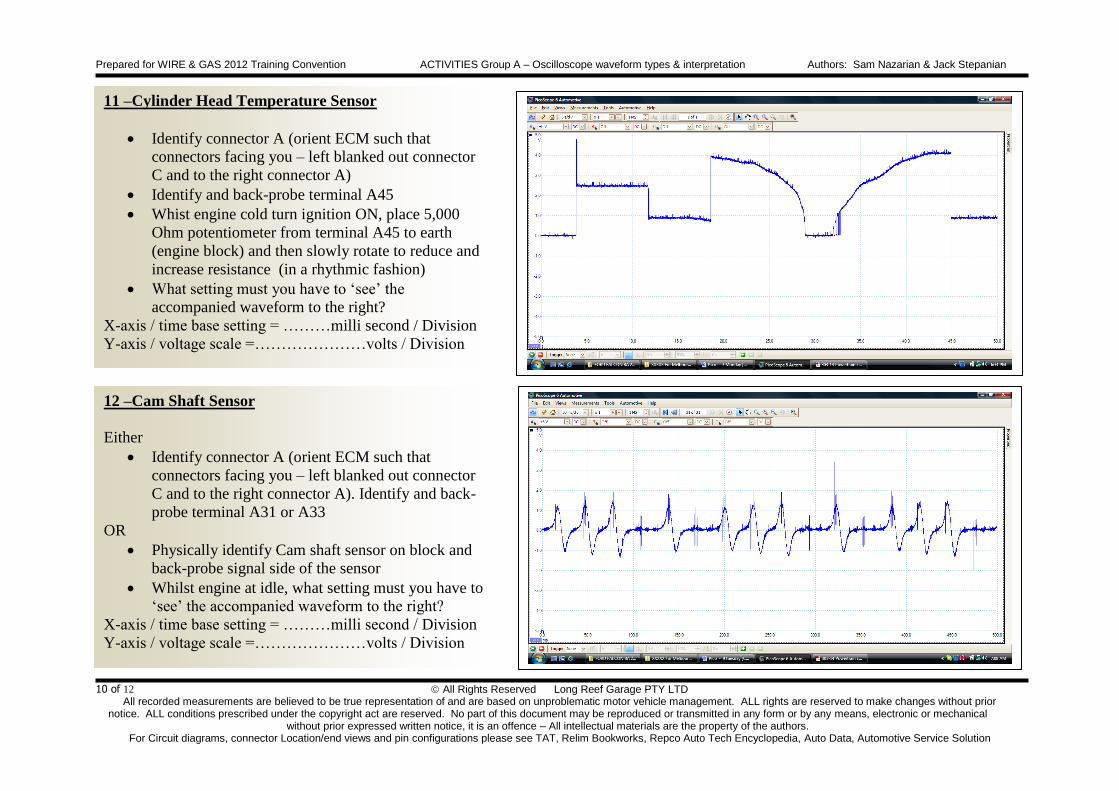
12 –Cam Shaft Sensor
Either
Identify connector A (orient ECM such that
connectors facing you – left blanked out connector
C and to the right connector A). Identify and back-
probe terminal A31 or A33
OR
Physically identify Cam shaft sensor on block and
back-probe signal side of the sensor
Whilst engine at idle, what setting must you have to
‘see’ the accompanied waveform to the right?
X-axis / time base setting = ………milli second / Division
Y-axis / voltage scale =…………………volts / Division
11 –Cylinder Head Temperature Sensor
Identify connector A (orient ECM such that
connectors facing you – left blanked out connector
C and to the right connector A)
Identify and back-probe terminal A45
Whist engine cold turn ignition ON, place 5,000
Ohm potentiometer from terminal A45 to earth
(engine block) and then slowly rotate to reduce and
increase resistance (in a rhythmic fashion)
What setting must you have to ‘see’ the
accompanied waveform to the right?
X-axis / time base setting = ………milli second / Division
Y-axis / voltage scale =…………………volts / Division

Prepared for WIRE & GAS 2012 Training Convention ACTIVITIES Group A – Oscilloscope waveform types & interpretation Authors: Sam Nazarian & Jack Stepanian
All Rights Reserved Long Reef Garage PTY LTD All recorded measurements are believed to be true representation of and are based on unproblematic motor vehicle management. ALL rights are reserved to make changes without prior
notice. ALL conditions prescribed under the copyright act are reserved. No part of this document may be reproduced or transmitted in any form or by any means, electronic or mechanical without prior expressed written notice, it is an offence – All intellectual materials are the property of the authors.
For Circuit diagrams, connector Location/end views and pin configurations please see TAT, Relim Bookworks, Repco Auto Tech Encyclopedia, Auto Data, Automotive Service Solution
11 of 12
Waveform of your own choice
Capture a waveform and note X and Y axis
Explain captured waveform - Ignition On, Crank,
Start, Run, Snap-throttle, back to idle then ignition
OFF (if applicable)
Thank You
13 –Cam Shaft Actuator
Either
Identify connector A (orient ECM such that
connectors facing you – left blanked out connector
C and to the right connector A). Identify and back-
probe terminal A5 or A6
OR
Physically identify Cam shaft sensor on block and
back-probe signal side of the sensor
Whilst ‘snap throttle, what setting must you have to
‘see’ the accompanied waveform to the right?
X-axis / time base setting = ………milli second / Division
Y-axis / voltage scale =…………………volts / Division

Prepared for WIRE & GAS 2012 Training Convention ACTIVITIES Group A – Oscilloscope waveform types & interpretation Authors: Sam Nazarian & Jack Stepanian
All Rights Reserved Long Reef Garage PTY LTD All recorded measurements are believed to be true representation of and are based on unproblematic motor vehicle management. ALL rights are reserved to make changes without prior
notice. ALL conditions prescribed under the copyright act are reserved. No part of this document may be reproduced or transmitted in any form or by any means, electronic or mechanical without prior expressed written notice, it is an offence – All intellectual materials are the property of the authors.
For Circuit diagrams, connector Location/end views and pin configurations please see TAT, Relim Bookworks, Repco Auto Tech Encyclopedia, Auto Data, Automotive Service Solution
12 of 12
Notes