Active Integrator for Rogowski Coil Reference Design … the output of the Rogowski coil is...
47
Copyright © 2016, Texas Instruments Incorporated 5-V DC supply input Rogowski coil output Precision measurement output LDO (LP2951ACSD/NOPB) LDO (TPS72325DBVT) Charge pump (TPS60403DBV) +V + R1 RI RF +V + RI RF C Precision measurement Amplifier (OPA2188-1A) Active integrator (OPA2188-1B) +V + R1 R2 RF R3 Level shifter (OPA188) +V + R1 R2 RF R3 Level shifter (OPA188) Fast settling Active integrator (OPA2188-1B) Amplifier (OPA2188-1A) +V + RI RF C +V + R1 RI RF Fast settling output V+ V V+ V 2.5 V 2.5 V 2.5 V 2.5 V 2.5 V VE_UNREG 2.5 V 5 V V+ V GND Voltage reference (LM4040AIM3-2.5/NOPB) +V + Buffer (OPA188) 5 V GND GND Jumper selection REF_2.5 V TIDA-00777 1 TIDUBY4A – April 2016 – Revised September 2016 Submit Documentation Feedback Copyright © 2016, Texas Instruments Incorporated Active Integrator for Rogowski Coil Reference Design With Improved Accuracy for Relays and Breakers TI Designs Active Integrator for Rogowski Coil Reference Design With Improved Accuracy for Relays and Breakers All trademarks are the property of their respective owners. Design Overview The TIDA-00777 is an op amp-based active integrator design that covers a wide input of current range measurement using a Rogowski coil with excellent accuracy, linearity, stability, and repeatability. The integrator uses a precision amplifier with very low offset and temperature drift. Two configurations of the integrator are shown: one for precision measurement with less than 3° phase error, and the other for fast response time (< 15 ms). While the output signal is bipolar, an optional level shifting stage can be used when unipolar output is required. Design Resources TIDA-00777 Design Folder OPA2188 Product Folder OPA188 Product Folder LM4040-N Product Folder LP2951-N Product Folder TPS60403 Product Folder TPS723 Product Folder ASK Our E2E Experts Design Features • Current Measurement Using Rogowski (di/dt) Coil- Based Current Sensor: – 0.5 to 200-A for Precision Measurement Within ±0.5% Accuracy – 0.5 to 200 A for Fast Settling Within ±1% Accuracy of Final Measured Value • Integration Achieved in Hardware With – RC, Low-Noise Density Op Amp Based Integrator Design – Parallel Paths With Low-Phase Shift Error and Fast Output Response Time • Phase Error < 3° for 50 and 60 Hz for Precision Measurement • Phase Error < 15° for 50 and 60 Hz for Fast Settling • Op Amp Gains Designed for Integrating Rogowski Coil (Pulse, PA3209NL) Specification: 463 μV/A at 50 Hz; 556 μV/A at 60 Hz • Operates With a Single DC Input • AFE Output Type: – Bipolar: V OUT = ±2.5 V – Unipolar: V OUT = 0 to 5 V, V CM = 2.5 V • Interfaced to MSP430F6779 Metering SoC for Accuracy Measurement and ADS131E08 Featured Applications • Protection Relays and IEDs • Circuit Breakers
Transcript of Active Integrator for Rogowski Coil Reference Design … the output of the Rogowski coil is...

Copyright © 2016, Texas Instruments Incorporated
5-V DC supply input
Rogowski coil output
Precision measurement output
LDO(LP2951ACSD/NOPB)
LDO(TPS72325DBVT)
Charge pump(TPS60403DBV)
+V+
í
R1
RI
RF
+V+
í
RI
RF
C
Precision measurementAmplifier (OPA2188-1A) Active integrator (OPA2188-1B)
+V+
í
R1
R2
RF
R3
Level shifter (OPA188)
+V+
í
R1
R2
RF
R3
Level shifter (OPA188)Fast settlingActive integrator (OPA2188-1B) Amplifier (OPA2188-1A)
+V+
í
RI
RF
C
+V+
í
R1
RI
RF Fast settling output
V+ Ví
V+ Ví2.5 V í2.5 V
2.5 V í2.5 V
2.5 V
íVE_UNREG
í2.5 V
5 VV+
VíGND
Voltage reference(LM4040AIM3-2.5/NOPB)
+V+
í
Buffer (OPA188)
5 V GND
GND
Jumper selection
REF_2.5 V
TIDA-00777
1TIDUBY4A–April 2016–Revised September 2016Submit Documentation Feedback
Copyright © 2016, Texas Instruments Incorporated
Active Integrator for Rogowski Coil Reference Design With ImprovedAccuracy for Relays and Breakers
TI DesignsActive Integrator for Rogowski Coil Reference DesignWith Improved Accuracy for Relays and Breakers
All trademarks are the property of their respective owners.
Design OverviewThe TIDA-00777 is an op amp-based active integratordesign that covers a wide input of current rangemeasurement using a Rogowski coil with excellentaccuracy, linearity, stability, and repeatability. Theintegrator uses a precision amplifier with very lowoffset and temperature drift. Two configurations of theintegrator are shown: one for precision measurementwith less than 3° phase error, and the other for fastresponse time (< 15 ms). While the output signal isbipolar, an optional level shifting stage can be usedwhen unipolar output is required.
Design Resources
TIDA-00777 Design FolderOPA2188 Product FolderOPA188 Product FolderLM4040-N Product FolderLP2951-N Product FolderTPS60403 Product FolderTPS723 Product Folder
ASK Our E2E Experts
Design Features• Current Measurement Using Rogowski (di/dt) Coil-
Based Current Sensor:– 0.5 to 200-A for Precision Measurement Within
±0.5% Accuracy– 0.5 to 200 A for Fast Settling Within ±1%
Accuracy of Final Measured Value• Integration Achieved in Hardware With
– RC, Low-Noise Density Op Amp BasedIntegrator Design
– Parallel Paths With Low-Phase Shift Error andFast Output Response Time• Phase Error < 3° for 50 and 60 Hz for
Precision Measurement• Phase Error < 15° for 50 and 60 Hz for Fast
Settling• Op Amp Gains Designed for Integrating Rogowski
Coil (Pulse, PA3209NL) Specification: 463 µV/A at50 Hz;556 µV/A at 60 Hz
• Operates With a Single DC Input• AFE Output Type:
– Bipolar: VOUT = ±2.5 V– Unipolar: VOUT = 0 to 5 V, VCM = 2.5 V
• Interfaced to MSP430F6779 Metering SoC forAccuracy Measurement and ADS131E08
Featured Applications• Protection Relays and IEDs• Circuit Breakers

Key System Specifications www.ti.com
2 TIDUBY4A–April 2016–Revised September 2016Submit Documentation Feedback
Copyright © 2016, Texas Instruments Incorporated
Active Integrator for Rogowski Coil Reference Design With ImprovedAccuracy for Relays and Breakers
An IMPORTANT NOTICE at the end of this TI reference design addresses authorized use, intellectual property matters and otherimportant disclaimers and information.
1 Key System Specifications
Table 1. Key System Specifications
NO PARAMETERS SPECIFICATION1 Current sensor type Rogowski coil
2 Rogowski coil output specificationPulse part number PA3209NL:
• 463 µV/A at 50 Hz• 556 µV/A at 60 Hz
3 Number of input currents One4 Measurement frequency 50 or 60 Hz5 Integrator type Active
6 Integrator outputTwo options:
• Measurement path for reduced phase error• Fast settling path for fast response
7 Output voltage scalingSelectable unipolar or bipolar output:
• 0 to 5 V with VCM = 2.5 V• ±2.5 V
Precision measurement Fast settling (±5% of finalmeasured value)
8 AC current measurement range 0.25 to 200 A 0.5 to 200 A9 Accuracy < ±0.5% < ± 1.0%10 Current measurement linearity (from 1 to 200 A) < ±0.3% < ± 0.3%11 Phase angle error < 3° < 15°12 Temperature drift (–10°C to 60°C) < ±150 PPM/°C < ± 300 PPM/°C13 Repeatability σ max (%) < ±0.2% < ±0.2%14 Integrator time constant ~100 ms ~15 ms15 External DC power supply input 5 V ± 0.1 V, ≤ 20 mA

IP
VS
www.ti.com System Description
3TIDUBY4A–April 2016–Revised September 2016Submit Documentation Feedback
Copyright © 2016, Texas Instruments Incorporated
Active Integrator for Rogowski Coil Reference Design With ImprovedAccuracy for Relays and Breakers
2 System DescriptionGrid infrastructure applications cover protection, control, and monitoring of systems that generate,transmit, and distribute power. These systems incorporate various sensor elements for measuring inputvoltages and currents accurately.
2.1 Protection RelaysProtection relays provide protection to grid equipment during fault conditions by monitoring multiplevoltages and currents. If the relays detect a stressed condition, a trip signal is sent to the circuit breaker toisolate the faulty section from the power system. Protection relays accurately measure current inputs usingcurrent transformers (CTs), Rogowski coils, or shunts and voltage inputs using potential transformers(PTs) or potential dividers. Additionally, protection relays do precise measurement. They have auxiliarypower (AC or DC).
2.2 Circuit BreakersCircuit breakers use trip elements to provide circuit protection for different applications. These tripelements protect against thermal overloads, short circuits, and arcing ground faults. The trip unit is thebrains of the circuit breaker. The function of the trip unit is to trip the operating mechanism in the event ofa short circuit or a prolonged overload of current. Electronic trip units measure RMS current providingimproved trip performance compared to conventional trip units.
Circuit breakers have a making current release (MCR) feature. MCR enables an instantaneous trip when abreaker is closed on a faulted circuit to open with no intended delay. The making current releasefunctionality is active for only a short preset time after the circuit breaker is closed. In such a case, thebreaker must power on, quickly detect the fault, generate trip signal, and disconnect. Fast settling is a keyrequirement.
Current sensors with a wide range is needed to measure currents from amperes in normal conditions to100's of amperes in short-circuit conditions. A Rogowski coil is suitable because of its linear output rangeover a wide input current.
2.3 Rogowski Coil-Based Current SensorA Rogowski coil is an air cored (non-magnetic) toroidal windings placed round the conductor. Analternating magnetic field produced by the current in the primary conductor (IP) induces a voltage (VS) inthe coil. Due to its non-magnetic core, the output of the coil does not saturate for a large primary current.
Figure 1. Rogowski Coil Operating Principle

System Description www.ti.com
4 TIDUBY4A–April 2016–Revised September 2016Submit Documentation Feedback
Copyright © 2016, Texas Instruments Incorporated
Active Integrator for Rogowski Coil Reference Design With ImprovedAccuracy for Relays and Breakers
The output voltage of a Rogowski coil is proportional to the rate of change of the current in the primaryconductor, and it does not get affected by the DC current.
Rogowski coils with a wide current range can be used for both measurement and protection applications.They provide galvanic isolation from the primary circuit. Because Rogowski coils convert input current toan output voltage, no burden resistor is needed. This in turn reduces power consumption. Unlike currenttransformers, Rogowski coils are electrically safe when open.
Rogowski coils are of two types—rigid or flexible:• Rigid Rogowski coils are wound on a toroidal shape core made of epoxy, plastic, or other non-
magnetic materials.• Flexible Rogowski coils are wound over flexible material such as silicone or a rubber tube.
Figure 2. Rigid (Left) and Flexible Rogowski Coils (Right)
2.4 Rogowski Coil SelectionWhile rigid coils have better accuracy, flexible coils are convenient for measuring current in large or non-round shaped conductors such as bus bars. Flexible coils are preferred when current carrying conductorinterruption (electrical or mechanical) is not an option. The current measurement range of flexible coils canrun into 1000's of amps.
Whether rigid or flexible coils are used, some of the key parameters to consider include:• Dynamic range: Minimum to maximum current range that is required for the application• Linearity: Linear output voltage for a specified range of current• Accuracy: Output voltage accuracy for a specified range of current• Secondary output voltage: Sensitivity of the coil specified as µV/A for a given frequency (for example:
PA3209NL Rogowski coil from Pulse specifies 463 µV/A at 50 Hz, 556 µV/A at 60 Hz)• Phase shift error: Specifies the phase difference between the output voltage and input current• Primary-secondary isolation: Specifies the isolation barrier potential that the Rogowski coil can handle• Inner diameter: Specified in mm depending on the current

Copyright © 2016, Texas Instruments Incorporated
VIN VOUT
R
C
IT
VC = VO VT = VIN VIT
VIR VRR
XC
J
( )( )P
S
dI tV t M
dt= -
www.ti.com System Design Theory
5TIDUBY4A–April 2016–Revised September 2016Submit Documentation Feedback
Copyright © 2016, Texas Instruments Incorporated
Active Integrator for Rogowski Coil Reference Design With ImprovedAccuracy for Relays and Breakers
3 System Design TheoryThe voltage (VS) induced at the output of a Rogowski coil is proportional to the time rate of change ofcurrent flowing in the primary conductor (IP). The output voltage has a 90° phase shift and lags input for asinusoidal input current.
Because the output of the Rogowski coil is proportional to the derivative of the instantaneous primarycurrent, an integrator is required to retrieve the original current signal. The output voltage is linear, whichcan be used without integration in applications requiring only current measurement. For applicationsrequiring measurement of power, the phase difference between current and voltage is important andrequires phase shifting of the Rogowski current sensor output. This is done using an integrator. ARogowski integrator can be implemented in two ways:• Digital (software) integration: In a frequency domain, integration can be viewed as –20 dB/decade
attenuation and a constant –90° phase shift. The phase angle correction can be highly accurate whendone in the digital domain. This is because the phase and magnitude response of a digital integrator isvery close to ideal. The limitation of such architecture is that this requires a high-performance MCUwith digital filter implementation. This may delay processing during the start-up.
• Hardware integration: A hardware integrator can also be used for correcting the Rogowski currentsensor phase shift. This can be achieved using a passive integrator (resistors, capacitors) or an activeintegrator (combination of active (op amp) and passive elements). This TI Design implements a stableop amp-based active integrator that can be used over the useful temperature range.
An ideal hardware integrator would introduce a 90° phase shift; however, there are practical limitationswhen designing a hardware integrator that results in a phase error with respect to the expected phase shiftof 90°. Carefully choosing components minimizes the phase error variations.
3.1 Passive IntegratorA series resistor-capacitor (RC) network acts as an integrator for a larger output range Rogowski coil. Thevalue of an RC is dependent on the phase error that is acceptable for the application. The relationshipbetween the RC and the phase error can be established using the phasor diagram of an RC network asshown in Figure 3.
Figure 3. Passive Integrator (Left) and Phasor Diagram (Right)
As shown in the phasor diagram in Figure 3, VR and VC represent the drop across the resistor (R) andcapacitor (C). The drop across the resistor will be in phase and the capacitor will lag by 90° with regard tothe net current (IT) in the network. The output voltage (VO) is the voltage across the capacitor, and theinput voltage (VIN) is the vector sum of voltage drop across the resistor and capacitor.
The phase angle between VO (VC) and VIN (VT) is the phase difference between the integrator’s input andoutput, which should be close to 90°. The phase error, which is the deviation from an ideal value of 90°, isrepresented by φ in Figure 3. The larger the drop across the resistor (V'R) compared to the capacitiveimpedance, the smaller the phase angle error will be.
Phase Error
Line
Cyc
les
0 0.5 1 1.5 2 2.5 3 3.50
10
20
30
40
50
D005
1R C
2 f tan´ =
´ p ´ ´ F
CX 1tan
R 2 f C RF = =
´ p ´ ´ ´
System Design Theory www.ti.com
6 TIDUBY4A–April 2016–Revised September 2016Submit Documentation Feedback
Copyright © 2016, Texas Instruments Incorporated
Active Integrator for Rogowski Coil Reference Design With ImprovedAccuracy for Relays and Breakers
The values of R and C can be estimated based on the following equations:
(1)
where• φ = Target phase error for the design• XC = Capacitive impedance• R = Resistance• f = Input mains frequency
(2)
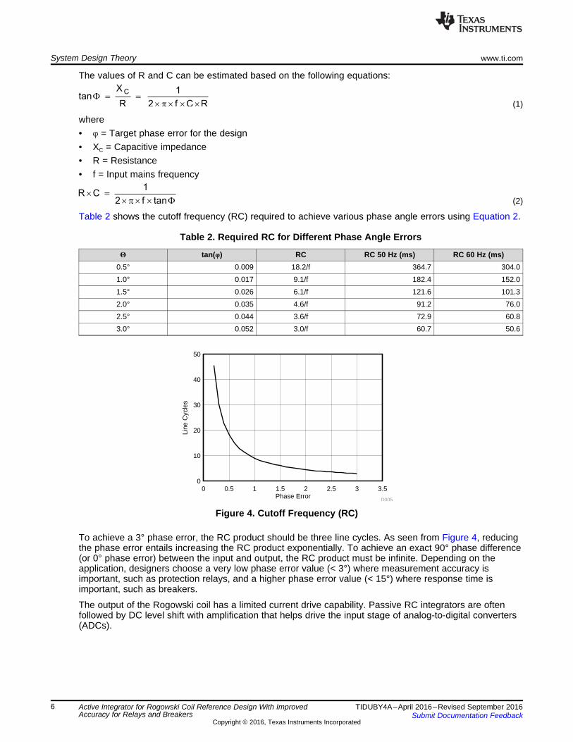
Table 2 shows the cutoff frequency (RC) required to achieve various phase angle errors using Equation 2.
Table 2. Required RC for Different Phase Angle Errors
Θ tan(φ) RC RC 50 Hz (ms) RC 60 Hz (ms)0.5° 0.009 18.2/f 364.7 304.01.0° 0.017 9.1/f 182.4 152.01.5° 0.026 6.1/f 121.6 101.32.0° 0.035 4.6/f 91.2 76.02.5° 0.044 3.6/f 72.9 60.83.0° 0.052 3.0/f 60.7 50.6
Figure 4. Cutoff Frequency (RC)
To achieve a 3° phase error, the RC product should be three line cycles. As seen from Figure 4, reducingthe phase error entails increasing the RC product exponentially. To achieve an exact 90° phase difference(or 0° phase error) between the input and output, the RC product must be infinite. Depending on theapplication, designers choose a very low phase error value (< 3°) where measurement accuracy isimportant, such as protection relays, and a higher phase error value (< 15°) where response time isimportant, such as breakers.
The output of the Rogowski coil has a limited current drive capability. Passive RC integrators are oftenfollowed by DC level shift with amplification that helps drive the input stage of analog-to-digital converters(ADCs).

MAX MIN F C
INV
MAX MIN 1
VOUT VOUT R XGAIN
VIN VIN R
-
= = -
-
www.ti.com System Design Theory
7TIDUBY4A–April 2016–Revised September 2016Submit Documentation Feedback
Copyright © 2016, Texas Instruments Incorporated
Active Integrator for Rogowski Coil Reference Design With ImprovedAccuracy for Relays and Breakers
3.2 Active IntegratorTo target a 3° phase error, the design uses a RC of 100 ms as per Table 3, which shows variouscombinations of R and C values for a 100-ms RC as an example.
Table 3. R and C combinations to Achieve 100-ms RC
RC RESISTOR CAPACITOR XC at 50 Hz XC : R100 ms 100 kΩ 1 µF 3.2 kΩ 1:31100 ms 500 kΩ 200 nF 15.9 kΩ 1:31100 ms 1 MΩ 100 nF 31.8 kΩ 1:31
The RC network acts as an attenuator. The drop across the capacitor gets attenuated by a factor of 32.This is a problem, especially at low-current levels when the output voltage of the Rogowski coil will be lessthan 100's of µV. This results in poor signal levels at the input of the ADC, causing accuracy andrepeatability issues at low-input current levels.
This problem can be solved using an active integrator as shown in Figure 5 where the RC element is inthe feedback path of an amplifier. Additionally, the –90° phase shift caused by the Rogowski coil can becorrected and the output scaled using R1.
Figure 5. Active Integrator
The equations for computing the integrator elements (RF, C) remain the same as shown in Section 3.1.
The gain of the amplifier can be adjusted using Equation 3, such that the output of the amplifier swings fullscale for the entire input range.
(3)

MAX MIN F
NON INV
MAX MIN 1
VOUT VOUT RGAIN 1
VIN VIN R-
-
= = +
-
System Design Theory www.ti.com
8 TIDUBY4A–April 2016–Revised September 2016Submit Documentation Feedback
Copyright © 2016, Texas Instruments Incorporated
Active Integrator for Rogowski Coil Reference Design With ImprovedAccuracy for Relays and Breakers
3.2.1 Inverting Amplifier ConfigurationThe input impedance of the amplifier is now dependent on the resistor R1, which in turn is dependent onthe previously mentioned gain requirements. For the parallel combination of RF and XC shown inEquation 3, the capacitive impedance dominates (see Table 3) as it is much smaller compared to theresistance. This parallel combination translates to a much smaller feedback resistance at line frequency.This lowers the value of R1 that is required to meet the gain requirements of the circuit.
A typical Rogowski coil does not have enough drive capability at its output. If the value of R1 is too low (in10's of kΩ), it introduces a gain error at the output of the coil. This can be partially addressed byincreasing XC, for a given RC cutoff frequency, thereby increasing R1. Not all Rogowski coils are able todrive such loads.
3.2.2 Non-Inverting Amplifier ConfigurationA non-inverting amplifier is introduced in this design between the output of the Rogowski coil and theinverting amplifier. The high-input impedance of a non-inverting amplifier is used to overcome thechallenge mentioned in Section 3.2.1. Additionally, the highest possible gain that is attainable isintroduced in this stage for better noise performance.
The gain of this stage can be computed using the maximum output swing that the amplifier can handle(based on the loading from the next stage) and the maximum input swing. For better linearity, ensure thatthe output does not exceed the datasheet specification on how close it can go to the rail under maximumloading condition.
(4)
Arriving at the system gain of the circuit (GAINNON-INV × GAININV) is an iterative process that involves• Optimizing the capacitance and resistance value for a given RC cutoff frequency• Selecting R1INV such that the GAININV is able to handle the overall output swing and input swing
requirement and that the Rogowski coil is able to drive it• Introducing a non-inverting amplifier between the Rogowski coil and the integrator if R1INV is too low.
This stage should handle most of the gain.• Adjusting R1INV such that the combined gain (GAINNON-INV × GAININV) meets the output and input swing
requirements
3.3 Component Selection
3.3.1 Integrator R and C Selection for Precision Measurement PathThis design has a target phase error of 3°.
Using Equation 2:• RC ≥ 3.0/f (3° phase error)• RC ≥ 60 ms (50-Hz line frequency being the worst case)
Considering a design margin for component tolerances, an RC time constant of ~100 ms is selected. A150-nF standard capacitor and a 680-kΩ resistor that results in 102 ms are used for this integrator.
Integrator capacitor should have low (< ±5%) tolerance and lower temperature drift. Polyester filmcapacitors have good frequency response and temperature stability. This design uses polyester filmcapacitor with ±5% tolerance. The resistors used in precision measurement path have a ±0.1% toleranceto improve accuracy and repeatability.

www.ti.com System Design Theory
9TIDUBY4A–April 2016–Revised September 2016Submit Documentation Feedback
Copyright © 2016, Texas Instruments Incorporated
Active Integrator for Rogowski Coil Reference Design With ImprovedAccuracy for Relays and Breakers
3.3.2 Integrator R and C Selection for Fast Settling PathFor the fast settling signal path where response time has to be minimized, this TI Design has a targetphase error of 15° to have integrator time constant of less than a cycle.
Using Equation 2:• RC ≥ 0.6/f for 15° phase error• RC ≥ 11.8 ms (50-Hz line frequency being the worst case)
Considering a design margin for component tolerances, an RC time constant of ~14 ms is targeted. A100-nF standard capacitor value and a 137-kΩ resistor that results in 13.7 ms are used for this integrator.
As explained in Section 3.3.1, this design uses the same polyester film type capacitor with a ±5%tolerance. However, to optimize cost for fast settling branch, ±1% tolerance resistors are used in thedesign except integrator feedback resistors (±0.1%).
3.3.3 Gain for Precision Measurement Path (Non-Inverting Amplifier + Inverting Integrator)Some of the amplifiers have approximately 100 to 250 mV of non-linear region of operation close to therail. This design uses an output swing of ±2.5 V – 0.35 V (with a 100-mV margin). For a current range of0.25 to 200 A, the Rogowski coil gives output of 115 µV to 92.6 mV. This design uses an input swing of100 µV to 100 mV, which results in an overall system gain of less than 15.
3.3.3.1 GAINNON-INV
To improve AC performance at a lower current, the Rogowski coil output is amplified before applying tothe integrator. Most of the gain is achieved in non-inverting amplifier stage.
Using Equation 4:• GAINNON-INV < 15• A 150-kΩ feedback resistor (RF) and 11.3-kΩ gain resistor (R1) that result in 14.3 for GAINNON-INV.
3.3.3.2 GAININV
GAININV must be < 1.05 to have a system gain (GAININV × GAINNON-INV) of 15.
Using Equation 3:• R1 > 20.2• A 680-kΩ integrator resistor (RF), a 150-nF integrator capacitor (C), and a 20.5-kΩ gain resistor (R1)
that result in 1.04 for GAININV.
As a result, GAINNON-INV × GAININV = 14.8 for precision measurement.

System Design Theory www.ti.com
10 TIDUBY4A–April 2016–Revised September 2016Submit Documentation Feedback
Copyright © 2016, Texas Instruments Incorporated
Active Integrator for Rogowski Coil Reference Design With ImprovedAccuracy for Relays and Breakers
3.3.4 Gain for Fast Settling Path (Inverting Integrator + Non-Inverting Amplifier)The combined system gain of all two stages will be same as the explanation in Section 3.3.3 for theprecision measurement path.
3.3.4.1 GAININV
Peak current during fault condition will be higher. In order to capture the current peak, the invertingintegration stage is introduced first. To minimize the Rogowski coil gain error because of R1, R1 is selectedas 30.9 kΩ.
Using Equation 3:• GAININV = 1.0• A 137-kΩ integrator resistor (RF), a 100-nF integrator capacitor (C), and a 30.9-kΩ gain resistor (R1)
that result in 1.0 for GAININV.
3.3.4.2 GAINNON-INV
GAINNON-INV must be < 15 to have a system gain (GAININV × GAINNON-INV) of 15.
Using Equation 4:• GAINNON-INV < 15• A 150-kΩ feedback resistor (RF) and a 11-kΩ gain resistor (R1) that result in 14.6 for GAINNON-INV.
3.3.5 DC Level ShifterIn case unipolar measurement is required, the DC level shifter stage is needed. The DC level shifter isafter the integrator stage for precision measurement and after the amplifier stage for fast settling. Thebipolar (±2.5 V) output needs to be DC level shifted to have unipolar (0 to 5 V) output with outputcommon-mode voltage (VCM) of 2.5 V.

Copyright © 2016, Texas Instruments Incorporated
5-V DC supply input
Rogowski coil output
Precision measurement output
LDO(LP2951ACSD/NOPB)
LDO(TPS72325DBVT)
Charge pump(TPS60403DBV)
+V+
í
R1
RI
RF
+V+
í
RI
RF
C
Precision measurementAmplifier (OPA2188-1A) Active integrator (OPA2188-1B)
+V+
í
R1
R2
RF
R3
Level shifter (OPA188)
+V+
í
R1
R2
RF
R3
Level shifter (OPA188)Fast settlingActive integrator (OPA2188-1B) Amplifier (OPA2188-1A)
+V+
í
RI
RF
C
+V+
í
R1
RI
RF Fast settling output
V+ Ví
V+ Ví2.5 V í2.5 V
2.5 V í2.5 V
2.5 V
íVE_UNREG
í2.5 V
5 VV+
VíGND
Voltage reference(LM4040AIM3-2.5/NOPB)
+V+
í
Buffer (OPA188)
5 V GND
GND
Jumper selection
REF_2.5 V
TIDA-00777
www.ti.com Block Diagram
11TIDUBY4A–April 2016–Revised September 2016Submit Documentation Feedback
Copyright © 2016, Texas Instruments Incorporated
Active Integrator for Rogowski Coil Reference Design With ImprovedAccuracy for Relays and Breakers
4 Block Diagram
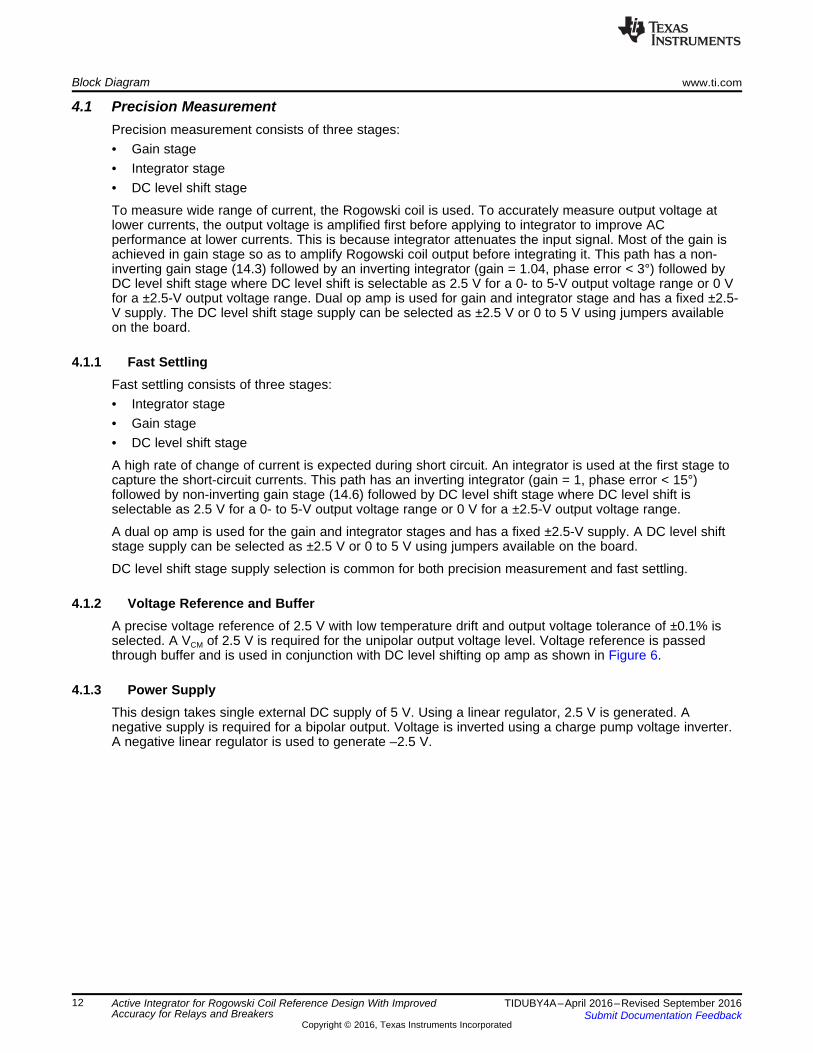
Figure 6. TIDA-00777 Block Diagram
The TIDA-00777 consists of four sections:• Precision measurement• Fast settling• Voltage reference and buffer• Power supply
Block Diagram www.ti.com
12 TIDUBY4A–April 2016–Revised September 2016Submit Documentation Feedback
Copyright © 2016, Texas Instruments Incorporated
Active Integrator for Rogowski Coil Reference Design With ImprovedAccuracy for Relays and Breakers
4.1 Precision MeasurementPrecision measurement consists of three stages:• Gain stage• Integrator stage• DC level shift stage
To measure wide range of current, the Rogowski coil is used. To accurately measure output voltage atlower currents, the output voltage is amplified first before applying to integrator to improve ACperformance at lower currents. This is because integrator attenuates the input signal. Most of the gain isachieved in gain stage so as to amplify Rogowski coil output before integrating it. This path has a non-inverting gain stage (14.3) followed by an inverting integrator (gain = 1.04, phase error < 3°) followed byDC level shift stage where DC level shift is selectable as 2.5 V for a 0- to 5-V output voltage range or 0 Vfor a ±2.5-V output voltage range. Dual op amp is used for gain and integrator stage and has a fixed ±2.5-V supply. The DC level shift stage supply can be selected as ±2.5 V or 0 to 5 V using jumpers availableon the board.
4.1.1 Fast SettlingFast settling consists of three stages:• Integrator stage• Gain stage• DC level shift stage
A high rate of change of current is expected during short circuit. An integrator is used at the first stage tocapture the short-circuit currents. This path has an inverting integrator (gain = 1, phase error < 15°)followed by non-inverting gain stage (14.6) followed by DC level shift stage where DC level shift isselectable as 2.5 V for a 0- to 5-V output voltage range or 0 V for a ±2.5-V output voltage range.
A dual op amp is used for the gain and integrator stages and has a fixed ±2.5-V supply. A DC level shiftstage supply can be selected as ±2.5 V or 0 to 5 V using jumpers available on the board.
DC level shift stage supply selection is common for both precision measurement and fast settling.
4.1.2 Voltage Reference and BufferA precise voltage reference of 2.5 V with low temperature drift and output voltage tolerance of ±0.1% isselected. A VCM of 2.5 V is required for the unipolar output voltage level. Voltage reference is passedthrough buffer and is used in conjunction with DC level shifting op amp as shown in Figure 6.
4.1.3 Power SupplyThis design takes single external DC supply of 5 V. Using a linear regulator, 2.5 V is generated. Anegative supply is required for a bipolar output. Voltage is inverted using a charge pump voltage inverter.A negative linear regulator is used to generate –2.5 V.

www.ti.com Block Diagram
13TIDUBY4A–April 2016–Revised September 2016Submit Documentation Feedback
Copyright © 2016, Texas Instruments Incorporated
Active Integrator for Rogowski Coil Reference Design With ImprovedAccuracy for Relays and Breakers
4.2 Highlighted Products
4.2.1 OPA2188/OPA188An op amp is used at each stage of precision measurement and fast settling. Selecting an op amp iscritical for the design.
Key specifications for selecting an op amp for an integrator design include:• Low offset and offset drift helps in minimizing calibration as well as degradation in performance over
temperature.• Low bias current helps in minimizing the loading of the Rogowski coil, thereby reducing gain error.• Low voltage noise density improves repeatability and accuracy at low input currents of the Rogowski
coil.
The OPA2188 dual op amp is used in this design for integrator and gain stage. The OPA188 single opamp is used in this design for the DC level shift stage and to buffer voltage reference. Table 4 lists keyspecifications:
Table 4. Key Specifications of OPA2188 and OPA188
PART NUMBER OPA2188 OPA188Number of channels 2 1Total supply voltage (min) 4 4Total supply voltage (max) 36 36GBW (typ; MHz) 2 2Slew rate (typ; V/µs) 0.8 0.8Rail-to-rail In to V–, Out In to V–, OutVOS, Offset voltage at 25°C (max; mV) 0.025 0.025Offset drift (typ; µV/C) 0.03 0.03VN at 1 kHz (typ; nV/rtHz) 8.8 8.8IQ per channel (typ; mA) 0.385 0.425IO (typ; mA) 18 18CMRR (typ; dB) 114 114Operating temperature range (°C) –40 to 105 –40 to 105IIB (max; pA) 850 1400
GND
GND
GND
0.1µF
C5
0.1µF
C3
TP3
V_REF
4
3
2
1
5
V+
V-U1OPA188AIDBVR
100pF
C32
100k
R7
100k
R12
100k
R1
100k
R4
V+
V-
Copyright © 2016, Texas Instruments Incorporated
20.5k
R11
680k
R6
VM_GAIN
100kR34
GND
0R13
0.15uF
C7
7
5
6
48
U2B
OPA2188AID+5V
Copyright © 2016, Texas Instruments Incorporated
GND
GND
0.1µF
C1
0.1µF
C8
100pF
C6
300k
R32
1
3
2
48
U2AOPA2188AID
GND 0
R28
0
R43
+2.5V
+5V
-2.5V
150k
R5
10.5k
R9
11.3k
R10
TP15
TP16
Copyright © 2016, Texas Instruments Incorporated
Block Diagram www.ti.com
14 TIDUBY4A–April 2016–Revised September 2016Submit Documentation Feedback
Copyright © 2016, Texas Instruments Incorporated
Active Integrator for Rogowski Coil Reference Design With ImprovedAccuracy for Relays and Breakers
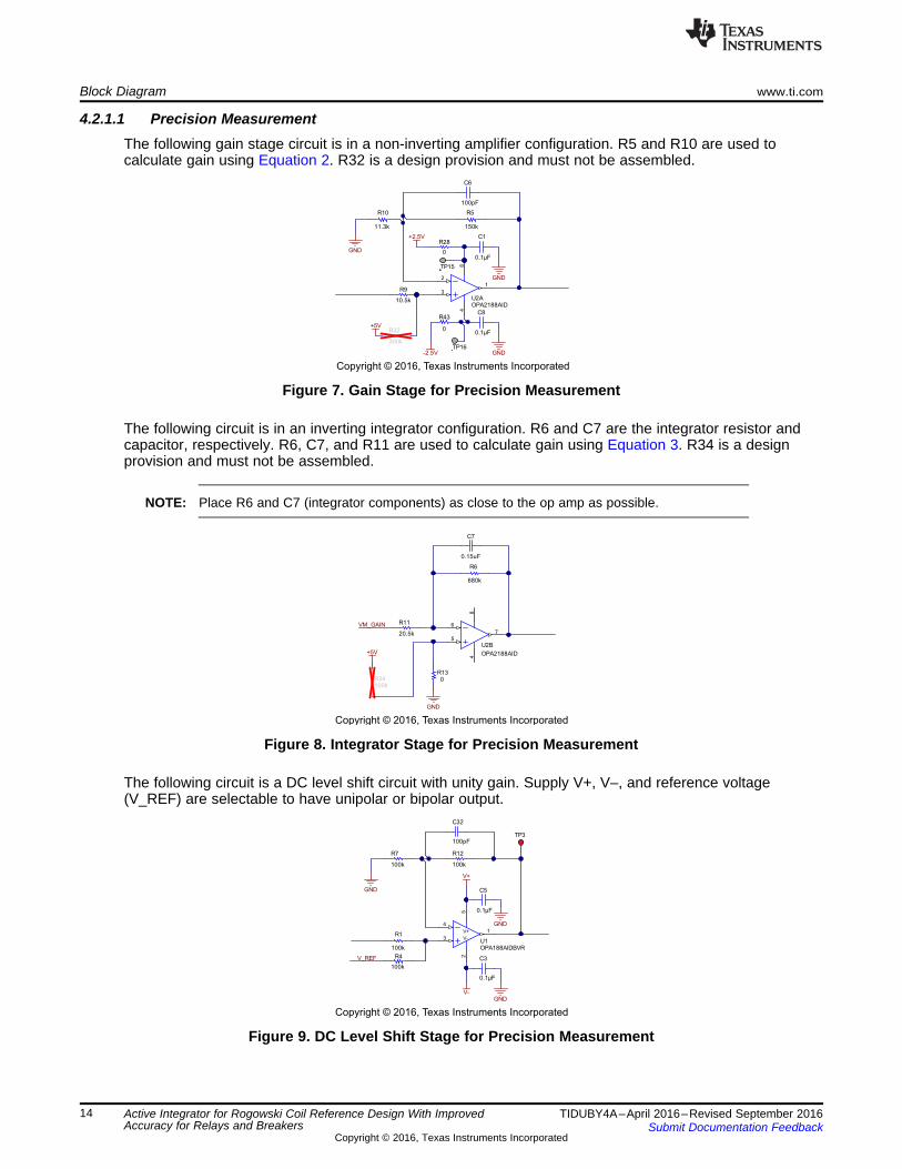
4.2.1.1 Precision MeasurementThe following gain stage circuit is in a non-inverting amplifier configuration. R5 and R10 are used tocalculate gain using Equation 2. R32 is a design provision and must not be assembled.
Figure 7. Gain Stage for Precision Measurement
The following circuit is in an inverting integrator configuration. R6 and C7 are the integrator resistor andcapacitor, respectively. R6, C7, and R11 are used to calculate gain using Equation 3. R34 is a designprovision and must not be assembled.
NOTE: Place R6 and C7 (integrator components) as close to the op amp as possible.
Figure 8. Integrator Stage for Precision Measurement
The following circuit is a DC level shift circuit with unity gain. Supply V+, V–, and reference voltage(V_REF) are selectable to have unipolar or bipolar output.
Figure 9. DC Level Shift Stage for Precision Measurement

100k
R50
100k
R45
100k
R46
GND
100k
R51
GND
GND
0.1µF
C35
0.1µF
C37
TP14
V_REF
4
3
2
1
5
V+
V-
U9OPA188AIDBVR
100pF
C34
V+
V-
Copyright © 2016, Texas Instruments Incorporated
100pF
C14
300k
R37
7
5
6
48
U4BOPA2188AID
150k
R20
GND
11.0k
R25
+5V
10.2k
R27
Copyright © 2016, Texas Instruments Incorporated
GND
GND
0.1µF
C13
0.1µF
C16
GND
0
R24
0.1µF
C10
1
3
2
48
U4AOPA2188AID
0
R47
0
R53
+2.5V
-2.5V
137k
R19
30.9k
R21
TP17
TP18
Copyright © 2016, Texas Instruments Incorporated
www.ti.com Block Diagram
15TIDUBY4A–April 2016–Revised September 2016Submit Documentation Feedback
Copyright © 2016, Texas Instruments Incorporated
Active Integrator for Rogowski Coil Reference Design With ImprovedAccuracy for Relays and Breakers
4.2.1.2 Fast SettlingThe following circuit is in inverting integrator configuration. R19 and C10 are the integrator resistor andcapacitor, respectively. R19, C10, and R21 are used to calculate gain using Equation 3.
NOTE: Place R6 and C7 (integrator components) as close to the op amp as possible.
Figure 10. Integrator Stage for Fast Settling
The following circuit is in non-inverting amplifier configuration. R20 and R25 are used to calculate gainusing Equation 2. R37 is a design provision and must not be assembled.
Figure 11. Gain Stage for Fast Settling
The following circuit is a DC level shift circuit with unity gain. Supply V+, V–, and reference voltage areselectable to have unipolar or bipolar output.
Figure 12. DC Level Shift Stage for Fast Settling

1
2
J6
282834-2
10µF
C24
10µF
C26
0.1µF
C25
0.1µF
C29
GND
10µF
C27
TP13
0.1µF
C28
TP8
GND
Green
12
D5
GND
GND
GND
100pF
C31
GND
0R30
GND
TP11 +2.5V
IN8
ERR5
GND4
VTAP6 SNS 2
DAP9
OUT1
FB7
SD3
U8
LP2951ACSD/NOPB
1000 ohm
L2
GND
100kR39
+5V
+5V
V+
20.0kR40
20.5kR41
SH-J2
510R31
5.6V
D2MMSZ5232B-7-F
GND
2.7V
D4MMSZ5223B-7-F
1 2 3
J8HTSW-103-07-G-S
Copyright © 2016, Texas Instruments Incorporated
4
3
2
1
5
V+
V-
U3OPA188AIDBVR
GND
GND
0.1µF
C11
GNDGND
0.1µF
C30
GND
V_R
EF
TP4
REF_2.5V
NCU5
LM4040AIM3-2.5/NOPB
2.55k
R36
GND
1µF
C9
GND
1µF
C15
100
R15
100
R22
+5V
+5V
123
J3
HTSW-103-07-G-S
Copyright © 2016, Texas Instruments Incorporated
Block Diagram www.ti.com
16 TIDUBY4A–April 2016–Revised September 2016Submit Documentation Feedback
Copyright © 2016, Texas Instruments Incorporated
Active Integrator for Rogowski Coil Reference Design With ImprovedAccuracy for Relays and Breakers
4.2.2 Voltage ReferenceThis TI Design provides a precise 2.5-V reference used for precision measurement and fast settlingunipolar output. It features the LM4040AIM3-2.5/NOPB, a 2.5-V precision micropower shunt voltagereference. The same voltage reference is connected to DC level shift circuit of both precisionmeasurement and fast settling. Reference voltage output is buffered using an op amp and is available onpin 1 of header J3. Short pin 2 of J3 with pin 3 of J3 for a 0- to 5-V output. Short pin 2 of J3 with pin 1 ofJ3 for a ±2.5-V output.
Figure 13. Circuit Diagram for 2.5-V Voltage Reference
4.2.3 2.5-V SupplyAn external 5-V DC supply must be connected on the J6 terminal block. The LP2951 family of voltageregulators is used to generate the required positive supply. The LP2951ACSD/NOPB is configured togenerate 2.5 V. A design option is provided for a positive supply of the DC level shift stage of precisionmeasurement and fast settling op amp (V+) to be 2.5 V or 5 V. V+ will be 2.5 V if pin 1 and 2 of header J8are short. V+ can be switched to 5 V if pin 2 and 3 of header J8 are short. Green LED is available forvisual indication. To change the rail voltage from 2.5 V, the resistor value of R41 and R40 must bechanged.
Figure 14. Circuit Diagram for 2.5-V Supply
GND GNDGND
1000 ohm
L1
0.1µF
C18
-VE_UNREG
2.7V
D1
MMSZ5223B-7-F10µF
C1910µF
C21
GND
10µF
C2018.0kR29
10.0kR38
GND
IN2
EN3
OUT5
1
GND
NR4
U6
TPS72325DBVT
1 2 3
J7HTSW-103-07-G-S
GND
V-TP10
-2.5V
SH-J3
Copyright © 2016, Texas Instruments Incorporated
D3
MBR0520LT1G
1µF
C22
1µF
C231µF
C17
GND
TP9-VE_UNREG
OUT1
IN2
CFLY-3
4
CFLY+5
GND
U7
TPS60403DBVR
Copyright © 2016, Texas Instruments Incorporated
www.ti.com Block Diagram
17TIDUBY4A–April 2016–Revised September 2016Submit Documentation Feedback
Copyright © 2016, Texas Instruments Incorporated
Active Integrator for Rogowski Coil Reference Design With ImprovedAccuracy for Relays and Breakers
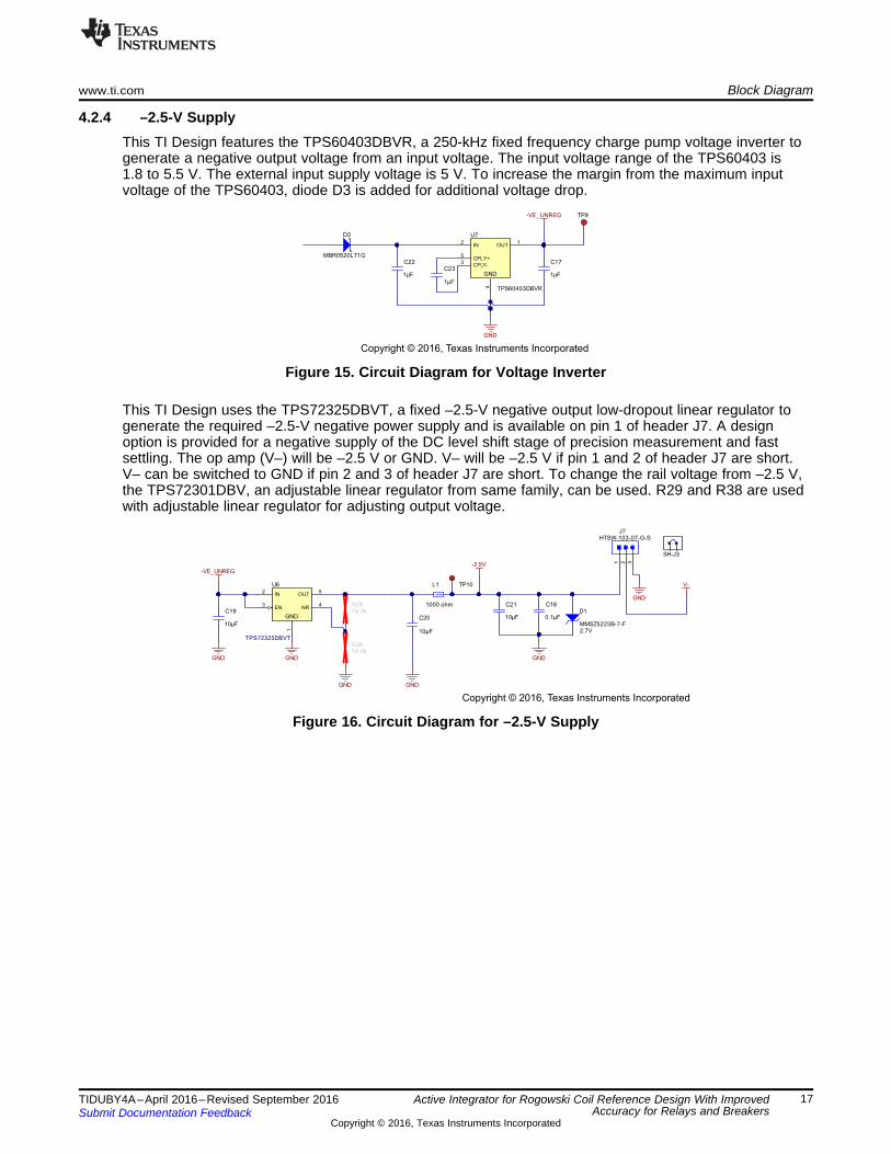
4.2.4 –2.5-V SupplyThis TI Design features the TPS60403DBVR, a 250-kHz fixed frequency charge pump voltage inverter togenerate a negative output voltage from an input voltage. The input voltage range of the TPS60403 is1.8 to 5.5 V. The external input supply voltage is 5 V. To increase the margin from the maximum inputvoltage of the TPS60403, diode D3 is added for additional voltage drop.
Figure 15. Circuit Diagram for Voltage Inverter
This TI Design uses the TPS72325DBVT, a fixed –2.5-V negative output low-dropout linear regulator togenerate the required –2.5-V negative power supply and is available on pin 1 of header J7. A designoption is provided for a negative supply of the DC level shift stage of precision measurement and fastsettling. The op amp (V–) will be –2.5 V or GND. V– will be –2.5 V if pin 1 and 2 of header J7 are short.V– can be switched to GND if pin 2 and 3 of header J7 are short. To change the rail voltage from –2.5 V,the TPS72301DBV, an adjustable linear regulator from same family, can be used. R29 and R38 are usedwith adjustable linear regulator for adjusting output voltage.
Figure 16. Circuit Diagram for –2.5-V Supply
1
2
J4
282834-2
GND
0
R49
VP_GAIN
100pF
C36100
R26
Copyright © 2016, Texas Instruments Incorporated
GND
1
2
J1
282834-2
0
R33
VM_INTEGRATOR
100pF
C33
100
R14
Copyright © 2016, Texas Instruments Incorporated
Block Diagram www.ti.com
18 TIDUBY4A–April 2016–Revised September 2016Submit Documentation Feedback
Copyright © 2016, Texas Instruments Incorporated
Active Integrator for Rogowski Coil Reference Design With ImprovedAccuracy for Relays and Breakers
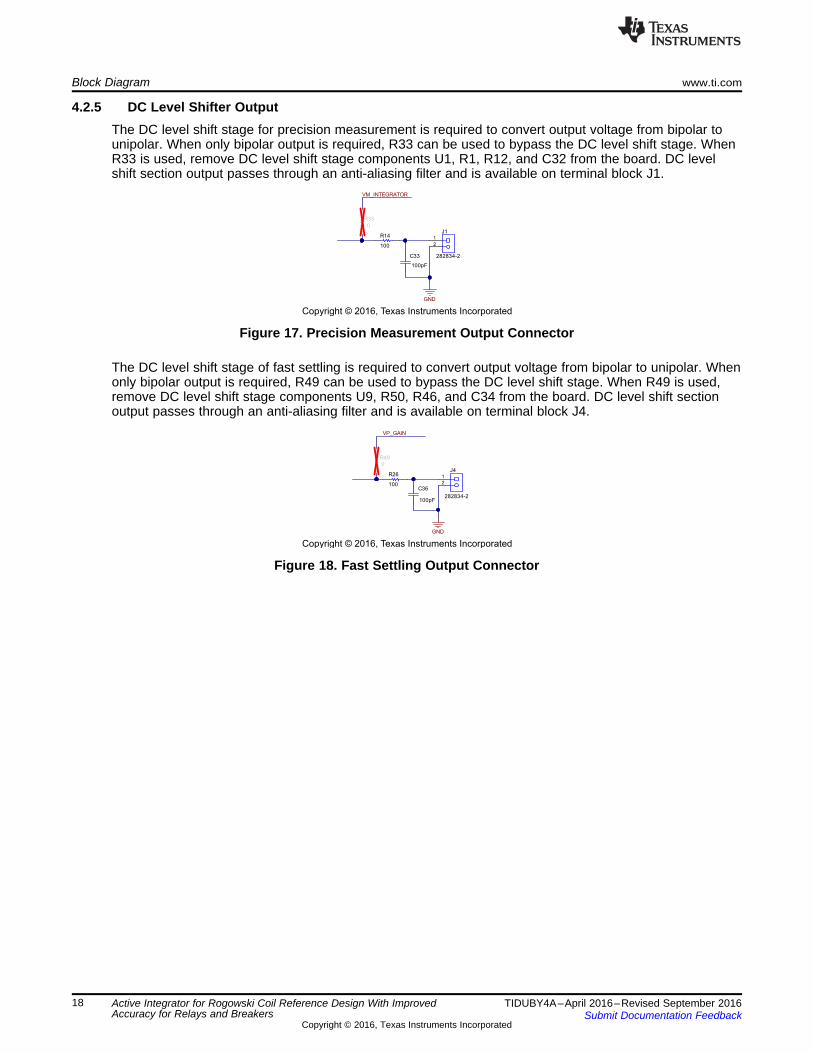
4.2.5 DC Level Shifter OutputThe DC level shift stage for precision measurement is required to convert output voltage from bipolar tounipolar. When only bipolar output is required, R33 can be used to bypass the DC level shift stage. WhenR33 is used, remove DC level shift stage components U1, R1, R12, and C32 from the board. DC levelshift section output passes through an anti-aliasing filter and is available on terminal block J1.
Figure 17. Precision Measurement Output Connector
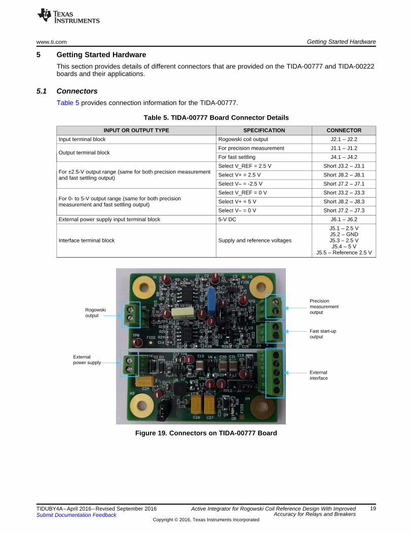
The DC level shift stage of fast settling is required to convert output voltage from bipolar to unipolar. Whenonly bipolar output is required, R49 can be used to bypass the DC level shift stage. When R49 is used,remove DC level shift stage components U9, R50, R46, and C34 from the board. DC level shift sectionoutput passes through an anti-aliasing filter and is available on terminal block J4.
Figure 18. Fast Settling Output Connector
Rogowski output
External power supply
Precision measurement output
Fast start-up output
External interface
www.ti.com Getting Started Hardware
19TIDUBY4A–April 2016–Revised September 2016Submit Documentation Feedback
Copyright © 2016, Texas Instruments Incorporated
Active Integrator for Rogowski Coil Reference Design With ImprovedAccuracy for Relays and Breakers
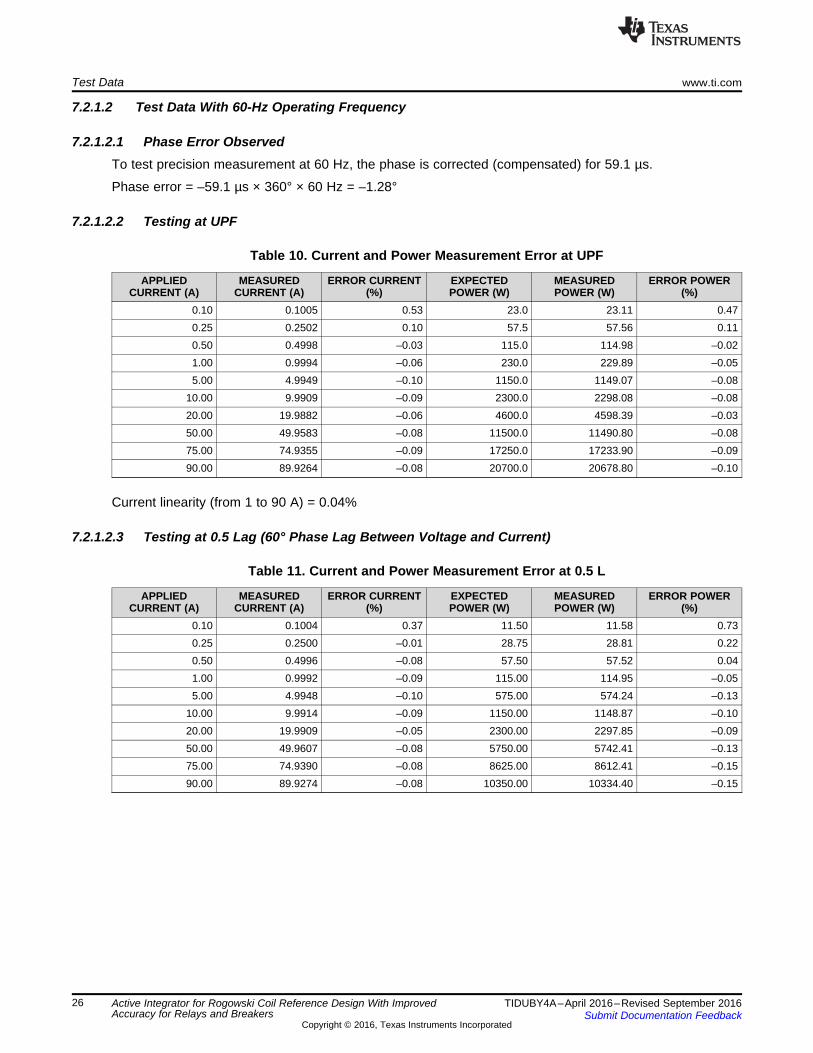
5 Getting Started HardwareThis section provides details of different connectors that are provided on the TIDA-00777 and TIDA-00222boards and their applications.
5.1 ConnectorsTable 5 provides connection information for the TIDA-00777.
Table 5. TIDA-00777 Board Connector Details
INPUT OR OUTPUT TYPE SPECIFICATION CONNECTORInput terminal block Rogowski coil output J2.1 – J2.2
Output terminal blockFor precision measurement J1.1 – J1.2For fast settling J4.1 – J4.2
For ±2.5-V output range (same for both precision measurementand fast settling output)
Select V_REF = 2.5 V Short J3.2 – J3.1Select V+ = 2.5 V Short J8.2 – J8.1Select V– = -2.5 V Short J7.2 – J7.1
For 0- to 5-V output range (same for both precisionmeasurement and fast settling output)
Select V_REF = 0 V Short J3.2 – J3.3Select V+ = 5 V Short J8.2 – J8.3Select V– = 0 V Short J7.2 – J7.3
External power supply input terminal block 5-V DC J6.1 – J6.2
Interface terminal block Supply and reference voltages
J5.1 – 2.5 VJ5.2 – GNDJ5.3 – 2.5 VJ5.4 – 5 V
J5.5 – Reference 2.5 V
Figure 19. Connectors on TIDA-00777 Board

UART interface connector
JTAG connector
Externalpower supply
TIDA-00777 outputPhase A²Current channel
Potential divider attenuated outputPhase A²Voltage channel
Copyright © 2016, Texas Instruments Incorporated
Voltage inputVoltage outputto TIDA-00222
R1 332k
R2 332k
R3 332k
R14 332k
R5 2.4k
Getting Started Hardware www.ti.com
20 TIDUBY4A–April 2016–Revised September 2016Submit Documentation Feedback
Copyright © 2016, Texas Instruments Incorporated
Active Integrator for Rogowski Coil Reference Design With ImprovedAccuracy for Relays and Breakers
Table 6 provides connection information for the TIDA-00222.
(1) Potential divider output circuit: The circuit shown in Figure 20 is the external potential divider. The output of the potential divideris interfaced to the TIDA-00222 board for voltage measurement.
Table 6. TIDA-00222 Board Connector Details
INPUT OR OUTPUT TYPE SPECIFICATION CONNECTORPhase A: Current channel Input terminalblock Output from TIDA-00777 board J10.1 – J10.2
Phase A: Voltage channel Input terminalblock Potential divider output (1) J13.1 – J13.2
External power supply input terminal block 5-V DC J9.1 – J9.2
UART interface connector for GUIcommunication
PM_UCA0TXD (Tx)PM_UCA0RXD (Rx)GND
J1.1J1.2J1.4
Figure 20. Potential Divider (Externally Connected) for Voltage Measurement on TIDA-00222
Figure 21. TIDA-00222 Board Connector Diagram

www.ti.com Getting Started Hardware
21TIDUBY4A–April 2016–Revised September 2016Submit Documentation Feedback
Copyright © 2016, Texas Instruments Incorporated
Active Integrator for Rogowski Coil Reference Design With ImprovedAccuracy for Relays and Breakers
To interface the TIDA-00777 board, the following modifications are done on the TIDA-00222 board:• Current measurement channel: Remove components R61, C31, C32, C18• Voltage measurement channel: Remove components R57, C37, C38, C21• Download firmware of available at http://www.ti.com/tool/TIDA-00454 to the TIDA-00222 board using
JTAG programming connector J8. Voltage and current channels are configured as phase A in thissoftware
• GUI is available at http://www.ti.com/lit/zip/slaa621
5.2 External DC Power SupplyThe external 5-V DC power supply is required to power up the board on connector J6. Green LED (D5)will glow once the 2.5-V supply is generated. Check the 2.5-V (TP11 with respect to TP8) and –2.5-V(TP10 with respect to TP8) supplies before applying input current.

Copyright © 2016, Texas Instruments Incorporated
PTS3.3CProgrammable
source
Voltage
Current
Rogowski sensor
Rogowski O/P
TIDA-00777board
Potential divider
TIDA-00777 O/P
MSP430F6779(TIDA-00222 board)
SD24, VA
SD24, IA UART
UART (TTL) to USB converter
GUI
Precision measurement or fast start-up
Test Setup www.ti.com
22 TIDUBY4A–April 2016–Revised September 2016Submit Documentation Feedback
Copyright © 2016, Texas Instruments Incorporated
Active Integrator for Rogowski Coil Reference Design With ImprovedAccuracy for Relays and Breakers
6 Test Setup
6.1 Test Setup ConnectionFigure 22 shows the test setup for the TIDA-00777 board. The TIDA-00222 board is interfaced with theTIDA-00777 board. A programmable current and voltage source (PTS3.3C test system) is used forapplying current to the TIDA-00777 board. Voltage is applied to the external potential divider, and outputof the potential divider is connected to the TIDA-00222 board. A 5-V power supply connection is shown inFigure 22.
Figure 22. Test Setup to Connect TIDA-00777 and TIDA-00222
NOTE: Connect the Rogowski sensor output to connector J2 of the TIDA-00777 board beforeapplying current.
6.2 TIDA-00222 BoardThe current input range for this design is 0.5 to 200 A for fast settling and 0.25 to 200 A for precisionmeasurement.
AC input parameters are measured using the TIDA-00222 MCU AFE board. The TIDA-00777 output ofprecision measurement or fast settling is interfaced with the TIDA-00222 MCU AFE to measure AC inputcurrent.
The following key features of the TIDA-00222 MCU AFE are used in this design:• MSP430F6779 SoC with seven simultaneous sigma-delta ADCs. In this design, one current and one
voltage channels are used• AC input current measurement: Up to 90 A• AC input voltage measurement: 230 V• GUI support for monitoring and calibrating current, voltage, active power, and phase angle through a
UART interface

www.ti.com Test Setup
23TIDUBY4A–April 2016–Revised September 2016Submit Documentation Feedback
Copyright © 2016, Texas Instruments Incorporated
Active Integrator for Rogowski Coil Reference Design With ImprovedAccuracy for Relays and Breakers
6.2.1 AC Input Measurement
6.2.1.1 Current MeasurementThe current is measured using the 24-bit sigma-delta (SD) ADC of the MSP430F6779, which is used inthe TIDA-00222 TI Design with the modifications specified in Section 6.1. Phase A is used formeasurement. At any given time, precision measurement or fast settling inputs can be taken.
6.2.1.2 Voltage MeasurementAlthough the TIDA-00777 TI Design is for current sensing, voltage measurement is required to computethe power and power factor, which is computed using cos φ = active power / apparent power, where φ isthe phase angle.
6.2.2 Calibrating and Viewing Results From PCSee Section 7.2 from the TIDA-00601 design guide (TIDU845) for details on calibrating and viewingresults.
6.3 Test SystemPTS3.3C with an accuracy class of 0.05% is used for measurement, which provides minimum uncertaintyduring measurement.
Figure 23. Test System (Including Programmable Power Source)

Test Data www.ti.com
24 TIDUBY4A–April 2016–Revised September 2016Submit Documentation Feedback
Copyright © 2016, Texas Instruments Incorporated
Active Integrator for Rogowski Coil Reference Design With ImprovedAccuracy for Relays and Breakers
7 Test Data
7.1 Functional Testing
Table 7. Functional Test Results
PARAMETERS SPECIFICATIONS OBSERVATION
Power supply
2.5-V DC 2.497-V DCCharge pump voltage inverter input 4.602-V DCCharge pump voltage inverter output –4.561-V DC–2.5-V DC –2.519-V DC
Reference voltage 2.5-V DC (REF_2.5V) 2.498-V DC
Precision measurement gainGain stage (× 14.3) 14.30Integrator stage (× 1.04) 1.05DC level shift stage (× 1.0) 1.00
Fast settling gainIntegrator stage (× 1.0) 1.02Gain stage (× 14.6) 14.70DC level shift stage (× 1.0) 1.00
7.2 Accuracy, Linearity, and Integrator Phase Error TestingVoltage and current are applied using the PTS3.3-C. Accuracy of the current and active power isobserved. Measurements were adjusted for gain and phase angle as required.
NOTE: Unless specified:• AC voltage and current values are in RMS.• The output voltage range is ±2.5 V.
7.2.1 Precision MeasurementThe applied voltage is 230-V AC.
7.2.1.1 Test Data With 50-Hz Operating Frequency
7.2.1.1.1 Phase Error ObservedTo test precision measurement at 50 Hz, the phase is corrected (compensated) for 90 µs.
Phase error = –90 µs × 360° × 50 Hz = –1.62°

Applied Current (A)
Err
or (
%)
0 10 20 30 40 50 60 70 80 90-0.2
-0.15
-0.1
-0.05
0
0.05
0.1
0.15
0.2
D001
UPF_Error - CurrentUPF_Error - Power0.5L_Error - Current0.5L_Error - Power
www.ti.com Test Data
25TIDUBY4A–April 2016–Revised September 2016Submit Documentation Feedback
Copyright © 2016, Texas Instruments Incorporated
Active Integrator for Rogowski Coil Reference Design With ImprovedAccuracy for Relays and Breakers
7.2.1.1.2 Testing at Unity Power Factor (UPF)
Table 8. Current and Power Measurement Error at UPF
APPLIEDCURRENT (A)
MEASUREDCURRENT (A)
ERROR CURRENT(%)
EXPECTEDPOWER (W)
MEASUREDPOWER (W)
ERROR POWER(%)
0.10 0.1005 0.53 23.0 23.10 0.450.25 0.2503 0.13 57.5 57.59 0.160.50 0.5002 0.04 115.0 115.09 0.071.00 1.0002 0.02 230.0 230.11 0.055.00 4.9981 –0.04 1150.0 1150.08 0.01
10.00 9.9992 –0.01 2300.0 2300.76 0.0320.00 20.0034 0.02 4600.0 4602.89 0.0650.00 49.9916 –0.02 11500.0 11502.60 0.0275.00 74.9854 –0.02 17250.0 17250.90 0.0190.00 89.9869 –0.01 20700.0 20700.00 0
Current linearity (from 1 to 90 A) = 0.06%
7.2.1.1.3 Testing at 0.5 Lag (60° Phase Lag Between Voltage and Current)
Table 9. Current and Power Measurement Error at 0.5 L
APPLIEDCURRENT (A)
MEASUREDCURRENT (A)
ERROR CURRENT(%)
EXPECTEDPOWER (W)
MEASUREDPOWER (W)
ERROR POWER(%)
0.10 0.1004 0.42 11.50 11.59 0.760.25 0.2500 –0.01 28.75 28.81 0.190.50 0.4996 –0.07 57.50 57.50 01.00 0.9993 –0.07 115.00 114.99 –0.015.00 4.9950 –0.10 575.00 574.22 –0.14
10.00 9.9940 –0.06 1150.00 1149.33 –0.0620.00 19.9920 –0.04 2300.00 2296.57 –0.1550.00 49.9618 –0.08 5750.00 5739.72 –0.1875.00 74.9416 –0.08 8625.00 8610.51 –0.1790.00 89.9367 –0.07 10350.00 10332.80 –0.17
Current linearity (from 1 to 90 A) = 0.06%
Figure 24. Precision Measurement Current and Power Accuracy for 50 Hz
Test Data www.ti.com
26 TIDUBY4A–April 2016–Revised September 2016Submit Documentation Feedback
Copyright © 2016, Texas Instruments Incorporated
Active Integrator for Rogowski Coil Reference Design With ImprovedAccuracy for Relays and Breakers
7.2.1.2 Test Data With 60-Hz Operating Frequency
7.2.1.2.1 Phase Error ObservedTo test precision measurement at 60 Hz, the phase is corrected (compensated) for 59.1 µs.
Phase error = –59.1 µs × 360° × 60 Hz = –1.28°
7.2.1.2.2 Testing at UPF
Table 10. Current and Power Measurement Error at UPF
APPLIEDCURRENT (A)
MEASUREDCURRENT (A)
ERROR CURRENT(%)
EXPECTEDPOWER (W)
MEASUREDPOWER (W)
ERROR POWER(%)
0.10 0.1005 0.53 23.0 23.11 0.470.25 0.2502 0.10 57.5 57.56 0.110.50 0.4998 –0.03 115.0 114.98 –0.021.00 0.9994 –0.06 230.0 229.89 –0.055.00 4.9949 –0.10 1150.0 1149.07 –0.08
10.00 9.9909 –0.09 2300.0 2298.08 –0.0820.00 19.9882 –0.06 4600.0 4598.39 –0.0350.00 49.9583 –0.08 11500.0 11490.80 –0.0875.00 74.9355 –0.09 17250.0 17233.90 –0.0990.00 89.9264 –0.08 20700.0 20678.80 –0.10
Current linearity (from 1 to 90 A) = 0.04%
7.2.1.2.3 Testing at 0.5 Lag (60° Phase Lag Between Voltage and Current)
Table 11. Current and Power Measurement Error at 0.5 L
APPLIEDCURRENT (A)
MEASUREDCURRENT (A)
ERROR CURRENT(%)
EXPECTEDPOWER (W)
MEASUREDPOWER (W)
ERROR POWER(%)
0.10 0.1004 0.37 11.50 11.58 0.730.25 0.2500 –0.01 28.75 28.81 0.220.50 0.4996 –0.08 57.50 57.52 0.041.00 0.9992 –0.09 115.00 114.95 –0.055.00 4.9948 –0.10 575.00 574.24 –0.13
10.00 9.9914 –0.09 1150.00 1148.87 –0.1020.00 19.9909 –0.05 2300.00 2297.85 –0.0950.00 49.9607 –0.08 5750.00 5742.41 –0.1375.00 74.9390 –0.08 8625.00 8612.41 –0.1590.00 89.9274 –0.08 10350.00 10334.40 –0.15

Applied Current (A)
Err
or (
%)
0 10 20 30 40 50 60 70 80 90-0.2
-0.15
-0.1
-0.05
0
0.05
0.1
0.15
0.2
0.25
D002
UPF_Error - CurrentUPF_Error - Power0.5L_Error - Current0.5L_Error - Power
www.ti.com Test Data
27TIDUBY4A–April 2016–Revised September 2016Submit Documentation Feedback
Copyright © 2016, Texas Instruments Incorporated
Active Integrator for Rogowski Coil Reference Design With ImprovedAccuracy for Relays and Breakers
Current linearity (from 1 to 90 A) = 0.05%
Figure 25. Precision Measurement Current and Power Accuracy for 60 Hz
7.2.2 Fast Settling
7.2.2.1 Test Data With 50-Hz Operating Frequency
7.2.2.1.1 Phase Error ObservedTo test fast settling at 50 Hz, the phase is corrected (compensated) for 720 µs.
Phase error = –720 µs × 360° × 50 Hz = –12.96°
7.2.2.1.2 Testing at UPF
Table 12. Current and Power Measurement Error at UPF
APPLIEDCURRENT (A)
MEASUREDCURRENT (A)
ERROR CURRENT(%)
EXPECTEDPOWER (W)
MEASUREDPOWER (W)
ERROR POWER(%)
0.25 0.2502 0.09 57.5 57.54 0.080.50 0.5000 0.01 115.0 115.00 01.00 1.0001 0.01 230.0 230.00 05.00 4.9981 –0.04 1150.0 1149.75 –0.02
10.00 10.0003 0 2300.0 2300.06 020.00 20.0052 0.03 4600.0 4601.08 0.0250.00 49.9968 –0.01 11500.0 11498.10 –0.0275.00 74.9932 –0.01 17250.0 17245.40 –0.0390.00 89.993.0 –0.01 20700.0 20693.00 –0.03
Current linearity (from 1 to 90 A) = 0.07%

Applied Current (A)
Err
or (
%)
0 10 20 30 40 50 60 70 80 90-0.1
-0.08
-0.06
-0.04
-0.02
0
0.02
0.04
0.06
D003
UPF_Error - CurrentUPF_Error - Power0.5L_Error - Current0.5L_Error - Power
Test Data www.ti.com
28 TIDUBY4A–April 2016–Revised September 2016Submit Documentation Feedback
Copyright © 2016, Texas Instruments Incorporated
Active Integrator for Rogowski Coil Reference Design With ImprovedAccuracy for Relays and Breakers
7.2.2.1.3 Testing at 0.5 Lag (60° Phase Lag Between Voltage and Current)
Table 13. Current and Power Measurement Error at 0.5 L
APPLIEDCURRENT (A)
MEASUREDCURRENT (A)
ERROR CURRENT(%)
EXPECTEDPOWER (W)
MEASUREDPOWER (W)
ERROR POWER(%)
0.5 0.4999 –0.03 57.5 57.50 –0.011.0 0.9999 –0.01 115.0 115.05 0.045.0 4.9980 –0.04 575.0 574.62 –0.07
10.0 9.9999 0 1150.0 1150.12 0.0120.0 20.0053 0.03 2300.0 2299.52 –0.0250.0 49.9973 –0.01 5750.0 5745.74 –0.0775.0 74.9954 –0.01 8625.0 8618.08 –0.0890.0 89.9980 0 10350.0 10344.50 –0.05
Current linearity (from 1 to 90 A) = 0.07%
Figure 26. Fast Settling Current and Power Accuracy for 50 Hz

www.ti.com Test Data
29TIDUBY4A–April 2016–Revised September 2016Submit Documentation Feedback
Copyright © 2016, Texas Instruments Incorporated
Active Integrator for Rogowski Coil Reference Design With ImprovedAccuracy for Relays and Breakers
7.2.2.2 Test Data With 60-Hz Operating Frequency
7.2.2.2.1 Phase Error ObservedTo test fast settling at 50 Hz, the phase is corrected (compensated) for 499.7 µs.
Phase shift = –499.7 µs × 360° × 50 Hz = –10.79°
7.2.2.2.2 Testing at UPF
Table 14. Current and Power Measurement Error at UPF
APPLIEDCURRENT (A)
MEASUREDCURRENT (A)
ERROR CURRENT(%)
EXPECTEDPOWER (W)
MEASUREDPOWER (W)
ERROR POWER(%)
0.25 0.2495 –0.20 57.5 57.25 –0.430.50 0.4992 –0.16 115.0 114.78 –0.191.00 0.9990 –0.10 230.0 229.75 –0.115.00 4.9978 –0.04 1150.0 1149.59 –0.04
10.00 9.9985 –0.02 2300.0 2299.75 –0.0120.00 20.0027 0.01 4600.0 4601.25 0.0350.00 49.9987 0 11500.0 11498.80 –0.0175.00 74.9962 –0.01 17250.0 17245.70 –0.0290.00 89.9917 –0.01 20700.0 20691.90 –0.04
Current linearity (from 1 to 90 A) = 0.11%
7.2.2.2.3 Testing at 0.5 Lag (60° Phase Lag Between Voltage and Current)
Table 15. Current and Power Measurement Error at 0.5 L
APPLIEDCURRENT (A)
MEASUREDCURRENT (A)
ERROR CURRENT(%)
EXPECTEDPOWER (W)
MEASUREDPOWER (W)
ERROR POWER(%)
0.5 0.4979 –0.42 57.5 57.41 –0.161.0 0.9979 –0.21 115.0 114.97 –0.035.0 4.9958 –0.09 575.0 575.02 0
10.0 9.9965 –0.04 1150.0 1150.74 0.0620.0 20.0045 0.02 2300.0 2302.20 0.1050.0 49.9979 0 5750.0 5753.55 0.0675.0 74.9952 –0.01 8625.0 8629.11 0.0590.0 90.0376 0.04 10350.0 10359.90 0.10

Applied Current (A)
Err
or (
%)
0 10 20 30 40 50 60 70 80 90-0.45
-0.4
-0.35
-0.3
-0.25
-0.2
-0.15
-0.1
-0.05
0
0.05
0.1
D004
UPF_Error - CurrentUPF_Error - Power0.5L_Error - Current0.5L_Error - Power
Test Data www.ti.com
30 TIDUBY4A–April 2016–Revised September 2016Submit Documentation Feedback
Copyright © 2016, Texas Instruments Incorporated
Active Integrator for Rogowski Coil Reference Design With ImprovedAccuracy for Relays and Breakers
Current linearity (from 1 to 90 A) = 0.25%
Figure 27. Fast Settling Current and Power Accuracy for 60 Hz
7.3 Accuracy and Linearity Testing for 0- to 5-V RangeCurrent is applied using the PTS3.3-C.
7.3.1 Precision Measurement
7.3.1.1 Test Data With 50-Hz Operating Frequency
Table 16. Current Measurement Error
APPLIED CURRENT (A) MEASURED CURRENT (A) ERROR — CURRENT (%)1 1.0008 0.082 2.0008 0.045 4.9992 –0.0210 10.0019 0.0220 20.0045 0.0250 49.9920 –0.0275 74.9928 –0.0190 90.0022 0.00
Current linearity (from 1 to 90 A) = 0.1%

www.ti.com Test Data
31TIDUBY4A–April 2016–Revised September 2016Submit Documentation Feedback
Copyright © 2016, Texas Instruments Incorporated
Active Integrator for Rogowski Coil Reference Design With ImprovedAccuracy for Relays and Breakers
7.3.1.2 Test Data With 60-Hz Operating Frequency
Table 17. Current Measurement Error
APPLIED CURRENT (A) MEASURED CURRENT (A) ERROR — CURRENT (%)1 1.0012 0.122 2.0011 0.055 4.9992 –0.0210 10.0001 0.0020 20.0051 0.0350 49.9916 –0.0275 74.9889 –0.0190 89.9923 –0.01
Current linearity = 0.14%
7.3.2 Fast Settling
7.3.2.1 Test Data With 50-Hz Operating Frequency
Table 18. Current Measurement Error
APPLIED CURRENT (A) MEASURED CURRENT (A) ERROR — CURRENT (%)1 0.9991 –0.092 1.9996 –0.025 4.9983 –0.0310 10.0010 0.0120 20.0071 0.0450 49.9913 –0.0275 74.9941 –0.0190 90.0032 0.00
Current linearity = 0.13%
7.3.2.2 Test Data With 60-Hz Operating Frequency
Table 19. Current Measurement Error
APPLIED CURRENT (A) MEASURED CURRENT (A) ERROR — CURRENT (%)1 1.0003 0.032 2.0012 0.065 4.9995 –0.0110 10.0013 0.0120 20.0084 0.0450 49.9956 –0.0175 74.9978 0.0090 90.0025 0.00
Current linearity = 0.07%
Test Data www.ti.com
32 TIDUBY4A–April 2016–Revised September 2016Submit Documentation Feedback
Copyright © 2016, Texas Instruments Incorporated
Active Integrator for Rogowski Coil Reference Design With ImprovedAccuracy for Relays and Breakers
7.4 Repeatability TestingThe repeatability testing is performed with 1-, 5-, 20-, 50-, and 90-A input currents.
To test repeatability:1. Power up the board and apply a 1-A current.2. After 5 min, capture current and power readings with UPF and 0.5 L (LAG) for specified input currents.3. Power off the board DC power supply for 15 min, including current input.4. Repeat the measurement cycle.
Repeatability error is computed as standard deviation (σ (%)).
7.4.1 Precision MeasurementTable 20 is a summary of the standard deviation (σ (%)) at UPF and 0.5 L for the applied currents.
Table 20. Summary of Standard Deviation (σ (%)) at UPF and 0.5 L
APPLIED CURRENT(A)
UPF 0.5 LERROR CURRENT σ
(%) ERROR POWER σ (%) ERROR CURRENT σ(%) ERROR POWER σ (%)
1 0.007 0.011 0.004 0.0365 0.007 0.029 0.009 0.045
20 0.015 0.022 0.015 0.03050 0.010 0.019 0.012 0.03990 0.007 0.020 0.009 0.055

www.ti.com Test Data
33TIDUBY4A–April 2016–Revised September 2016Submit Documentation Feedback
Copyright © 2016, Texas Instruments Incorporated
Active Integrator for Rogowski Coil Reference Design With ImprovedAccuracy for Relays and Breakers
7.4.1.1 Measurement Data
Table 21. Current Measurement Error at UPF
APPLIEDCURRENT
(A)
ERROR CURRENT (%) ERRORCURRENT
σ (%)REPEAT 1 REPEAT 2 REPEAT 3 REPEAT 4 REPEAT 5 REPEAT 6 REPEAT 7 REPEAT 8
1 0.053 0.060 0.041 0.044 0.050 0.043 0.044 0.042 0.0075 –0.034 –0.009 –0.017 –0.012 –0.016 –0.014 –0.017 –0.017 0.007
20 0.006 0.048 0.051 0.025 0.032 0.046 0.025 0.038 0.01550 –0.019 0.012 0.009 –0.003 0 0.011 0 0.003 0.01090 –0.008 0.015 0.012 0.008 0.010 0.011 0.005 0.008 0.007
Table 22. Current Measurement Error at 0.5 L
APPLIEDCURRENT
(A)
ERROR CURRENT (%) ERRORCURRENT
σ (%)REPEAT 1 REPEAT 2 REPEAT 3 REPEAT 4 REPEAT 5 REPEAT 6 REPEAT 7 REPEAT 8
1 0.027 0.023 0.023 0.022 0.024 0.017 0.014 0.020 0.0045 –0.034 –0.013 –0.021 –0.021 –0.024 –0.020 –0.002 –0.024 0.009
20 0.003 0.048 0.025 0.020 0.029 0.046 0.029 0.039 0.01550 –0.024 0.011 0.008 –0.001 0.001 0.014 0 0.004 0.01290 –0.009 0.017 0.014 0.014 0.008 0.013 0.006 0.016 0.009
Table 23. Power Measurement Error at UPF
APPLIEDCURRENT
(A)
ERROR POWER (%) ERRORCURRENT
σ (%)REPEAT 1 REPEAT 2 REPEAT 3 REPEAT 4 REPEAT 5 REPEAT 6 REPEAT 7 REPEAT 8
1 0.080 0.087 0.102 0.099 0.096 0.100 0.094 0.070 0.0115 –0.039 0.030 0.053 0.033 0.046 0.025 0.032 0.050 0.029
20 0.028 0.088 0.093 0.088 0.091 0.094 0.090 0.083 0.02250 –0.007 0.050 0.043 0.042 0.050 0.043 0.053 0.032 0.01990 –0.009 0.035 0.028 0.046 0.054 0.031 0.049 0.027 0.020
Table 24. Power Measurement Error at 0.5 L
APPLIEDCURRENT
(A)
ERROR POWER (%) ERRORCURRENT
σ (%)REPEAT 1 REPEAT 2 REPEAT 3 REPEAT 4 REPEAT 5 REPEAT 6 REPEAT 7 REPEAT 8
1 0.050 0.056 0.130 0.139 0.135 0.115 0.128 0.132 0.0365 –0.167 –0.096 –0.033 –0.096 –0.036 –0.090 –0.062 –0.037 0.045
20 –0.107 –0.058 –0.028 –0.033 –0.020 –0.059 –0.020 –0.067 0.03050 –0.131 –0.096 –0.109 –0.047 –0.031 –0.099 –0.033 –0.110 0.03990 –0.185 –0.100 –0.096 –0.031 –0.027 –0.103 –0.021 –0.099 0.055
Test Data www.ti.com
34 TIDUBY4A–April 2016–Revised September 2016Submit Documentation Feedback
Copyright © 2016, Texas Instruments Incorporated
Active Integrator for Rogowski Coil Reference Design With ImprovedAccuracy for Relays and Breakers
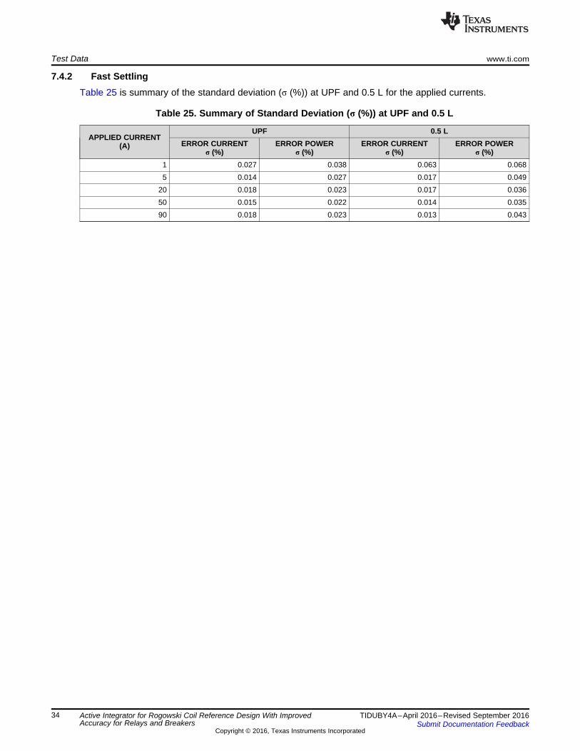
7.4.2 Fast SettlingTable 25 is summary of the standard deviation (σ (%)) at UPF and 0.5 L for the applied currents.
Table 25. Summary of Standard Deviation (σ (%)) at UPF and 0.5 L
APPLIED CURRENT(A)
UPF 0.5 LERROR CURRENT
σ (%)ERROR POWER
σ (%)ERROR CURRENT
σ (%)ERROR POWER
σ (%)1 0.027 0.038 0.063 0.0685 0.014 0.027 0.017 0.049
20 0.018 0.023 0.017 0.03650 0.015 0.022 0.014 0.03590 0.018 0.023 0.013 0.043
www.ti.com Test Data
35TIDUBY4A–April 2016–Revised September 2016Submit Documentation Feedback
Copyright © 2016, Texas Instruments Incorporated
Active Integrator for Rogowski Coil Reference Design With ImprovedAccuracy for Relays and Breakers
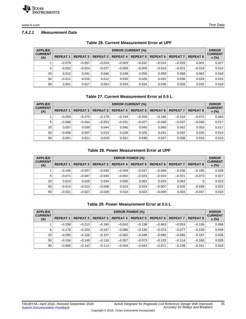
7.4.2.1 Measurement Data
Table 26. Current Measurement Error at UPF
APPLIEDCURRENT
(A)
ERROR CURRENT (%) ERRORCURRENT
σ (%)REPEAT 1 REPEAT 2 REPEAT 3 REPEAT 4 REPEAT 5 REPEAT 6 REPEAT 7 REPEAT 8
1 –0.079 –0.057 –0.024 –0.003 –0.032 –0.014 –0.033 0.001 0.0275 –0.052 –0.024 –0.027 –0.009 –0.005 –0.014 –0.021 –0.019 0.014
20 0.012 0.041 0.046 0.048 0.056 0.059 0.068 0.063 0.01850 –0.011 0.016 0.012 0.030 0.026 0.032 0.036 0.029 0.01590 0.001 0.017 0.064 0.034 0.034 0.036 0.039 0.032 0.018
Table 27. Current Measurement Error at 0.5 L
APPLIEDCURRENT
(A)
ERROR CURRENT (%) ERRORCURRENT
σ (%)REPEAT 1 REPEAT 2 REPEAT 3 REPEAT 4 REPEAT 5 REPEAT 6 REPEAT 7 REPEAT 8
1 –0.250 –0.275 –0.179 –0.154 –0.200 –0.166 –0.154 –0.072 0.0635 –0.068 –0.064 –0.053 –0.031 –0.027 –0.030 –0.037 –0.030 0.017
20 0.007 0.039 0.044 0.045 0.045 0.060 0.062 0.053 0.01750 –0.008 0.007 0.014 0.028 0.025 0.031 0.032 0.026 0.01490 –0.001 0.021 0.019 0.031 0.036 0.037 0.038 0.033 0.013
Table 28. Power Measurement Error at UPF
APPLIEDCURRENT
(A)
ERROR POWER (%) ERRORCURRENT
σ (%)REPEAT 1 REPEAT 2 REPEAT 3 REPEAT 4 REPEAT 5 REPEAT 6 REPEAT 7 REPEAT 8
1 –0.106 –0.057 –0.049 –0.009 –0.037 –0.008 –0.036 –0.105 0.0385 –0.071 –0.047 –0.040 –0.002 –0.023 –0.010 –0.021 –0.073 0.027
20 0.013 0.028 0.034 0.055 0.062 0.033 0.063 0 0.02350 –0.014 –0.013 –0.008 0.024 0.019 –0.007 0.020 –0.039 0.02290 –0.021 –0.027 –0.028 0.010 0.023 –0.006 0.003 –0.047 0.023
Table 29. Power Measurement Error at 0.5 L
APPLIEDCURRENT
(A)
ERROR POWER (%) ERRORCURRENT
σ (%)REPEAT 1 REPEAT 2 REPEAT 3 REPEAT 4 REPEAT 5 REPEAT 6 REPEAT 7 REPEAT 8
1 –0.208 –0.213 –0.160 –0.043 –0.138 –0.063 –0.053 –0.139 0.0685 –0.178 –0.203 –0.167 –0.086 –0.130 –0.073 –0.077 –0.139 0.049
20 –0.090 –0.106 –0.107 –0.062 –0.048 –0.085 –0.085 –0.167 0.03650 –0.104 –0.149 –0.116 –0.057 –0.073 –0.133 –0.114 –0.160 0.03590 –0.065 –0.142 –0.114 –0.054 –0.043 –0.071 –0.108 –0.161 0.043
Test Data www.ti.com
36 TIDUBY4A–April 2016–Revised September 2016Submit Documentation Feedback
Copyright © 2016, Texas Instruments Incorporated
Active Integrator for Rogowski Coil Reference Design With ImprovedAccuracy for Relays and Breakers
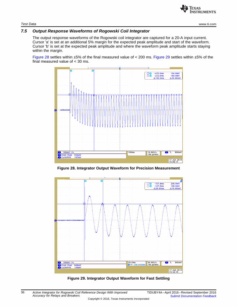
7.5 Output Response Waveforms of Rogowski Coil IntegratorThe output response waveforms of the Rogowski coil integrator are captured for a 20-A input current.Cursor 'a' is set at an additional 5% margin for the expected peak amplitude and start of the waveform.Cursor 'b' is set at the expected peak amplitude and where the waveform peak amplitude starts stayingwithin the margin.
Figure 28 settles within ±5% of the final measured value of < 200 ms. Figure 29 settles within ±5% of thefinal measured value of < 30 ms.
Figure 28. Integrator Output Waveform for Precision Measurement
Figure 29. Integrator Output Waveform for Fast Settling

www.ti.com Test Data
37TIDUBY4A–April 2016–Revised September 2016Submit Documentation Feedback
Copyright © 2016, Texas Instruments Incorporated
Active Integrator for Rogowski Coil Reference Design With ImprovedAccuracy for Relays and Breakers
7.6 Temperature Drift TestThis test is to test the TIDA-00777 board performance over temperature from –10°C to 60°C. Current andpower error is computed in PPM/°C for delta of 35°C at 25°C ambient temperature.
7.6.1 Precision Measurement
Table 30. Summary of Current and Power Measurement Accuracy Drift in PPM for 35°CTemperature Difference
APPLIEDCURRENT
(A)POWERFACTOR
ERROR AT 25°C ERROR AT 60°C Δ ERROR (FOR 35°C)CURRENT
(%)POWER
(%)CURRENT
(%)POWER
(%)CURRENT
(%)POWER
(%)CURRENT(PPM/°C)
POWER(PPM/°C)
0.5 UPF –0.03 –0.14 –0.40 –0.47 –0.37 –0.33 –106.2 –95.21.0 UPF –0.04 –0.09 –0.39 –0.44 –0.35 –0.35 –99.8 –99.55.0 UPF –0.04 –0.06 –0.37 –0.38 –0.33 –0.32 –93.9 –91.2
20.0 UPF 0.03 0.02 –0.29 –0.32 –0.32 –0.34 –90.4 –95.850.0 UPF 0 –0.02 –0.33 –0.36 –0.33 –0.34 –95.2 –97.990.0 UPF 0.01 –0.01 –0.32 –0.36 –0.33 –0.35 –95.5 –100.90.5 0.5 L –0.07 –0.37 –0.39 –0.73 –0.31 –0.36 –89.8 –102.91.0 0.5 L –0.04 –0.21 –0.33 –0.47 –0.29 –0.26 –83.5 –73.05.0 0.5 L –0.02 –0.20 –0.35 –0.52 –0.33 –0.32 –95.4 –90.9
20.0 0.5 L 0.05 –0.14 –0.31 –0.42 –0.35 –0.27 –101.0 –78.350.0 0.5 L 0.01 –0.13 –0.34 –0.41 –0.34 –0.28 –97.9 –80.190.0 0.5 L 0.01 –0.13 –0.32 –0.39 –0.34 –0.26 –96.6 –74.0
Table 31. Summary of Current and Power Measurement Accuracy Drift in PPM for –35°CTemperature Difference
APPLIEDCURRENT
(A)POWERFACTOR
ERROR AT 25°C ERROR AT –10°C Δ ERROR (FOR –35°C)CURRENT
(%)POWER
(%)CURRENT
(%)POWER
(%)CURRENT
(%)POWER
(%)CURRENT(PPM/°C)
POWER(PPM/°C)
0.5 UPF –0.03 –0.14 0.03 –0.07 0.07 0.07 19.4 18.91.0 UPF –0.04 –0.09 0.10 0.06 0.15 0.15 41.9 43.25.0 UPF –0.04 –0.06 0.16 0.15 0.20 0.20 56.6 57.9
20.0 UPF 0.03 0.02 0.24 0.22 0.21 0.20 61.1 58.050.0 UPF 0 –0.02 0.21 0.19 0.21 0.21 59.3 61.190.0 UPF 0.01 –0.01 0.21 0.19 0.20 0.20 57.5 56.70.5 0.5 L –0.07 –0.37 0.14 –0.40 0.21 –0.03 60.5 –8.41.0 0.5 L –0.04 –0.21 0.17 –0.11 0.21 0.10 59.2 27.35.0 0.5 L –0.02 –0.20 0.17 –0.04 0.19 0.17 54.1 47.3
20.0 0.5 L 0.05 –0.14 0.24 0.06 0.20 0.21 56.6 59.450.0 0.5 L 0.01 –0.13 0.21 0.04 0.20 0.17 57.1 49.090.0 0.5 L 0.01 –0.13 0.22 0.06 0.20 0.20 57.9 56.6

Test Data www.ti.com
38 TIDUBY4A–April 2016–Revised September 2016Submit Documentation Feedback
Copyright © 2016, Texas Instruments Incorporated
Active Integrator for Rogowski Coil Reference Design With ImprovedAccuracy for Relays and Breakers
7.6.1.1 Measurement Data
Table 32. 25°C Data
APPLIEDCURRENT (A)
POWERFACTOR (UPF
or 0.5 L)MEASURED
CURRENT (A)ERROR
CURRENT (%)EXPECTEDPOWER (W)
MEASUREDPOWER (W)
ERROR POWER(%)
0.5 UPF 0.500 –0.03 115.0 114.8 –0.141.0 UPF 1.000 –0.04 230.0 229.8 –0.095.0 UPF 4.998 –0.04 1150.0 1149.4 –0.06
20.0 UPF 20.005 0.03 4600.0 4600.9 0.0250.0 UPF 50.000 0 11500.0 11497.5 –0.0290.0 UPF 90.010 0.01 20700.0 20697.8 –0.010.5 0.5 L 0.500 –0.07 57.5 57.3 –0.371.0 0.5 L 1.000 –0.04 115.0 114.8 –0.215.0 0.5 L 4.999 –0.02 575.0 573.8 –0.20
20.0 0.5 L 20.009 0.05 2300.0 2296.7 –0.1450.0 0.5 L 50.004 0.01 5750.0 5742.6 –0.1390.0 0.5 L 90.013 0.01 10350.0 10336.1 –0.13
Table 33. –10°C Data
APPLIEDCURRENT (A)
POWERFACTOR (UPF
or 0.5 L)MEASURED
CURRENT (A)ERROR
CURRENT (%)EXPECTEDPOWER (W)
MEASUREDPOWER (W)
ERROR POWER(%)
0.5 UPF 0.500 0.03 115.0 114.9 –0.071.0 UPF 1.001 0.10 230.0 230.1 0.065.0 UPF 5.008 0.16 1150.0 1151.7 0.15
20.0 UPF 20.048 0.24 4600.0 4610.2 0.2250.0 UPF 50.104 0.21 11500.0 11522.1 0.1990.0 UPF 90.191 0.21 20700.0 20738.9 0.190.5 0.5 L 0.501 0.14 57.5 57.3 –0.401.0 0.5 L 1.002 0.17 115.0 114.9 –0.115.0 0.5 L 5.008 0.17 575.0 574.8 –0.04
20.0 0.5 L 20.049 0.24 2300.0 2301.5 0.0650.0 0.5 L 50.104 0.21 5750.0 5752.4 0.0490.0 0.5 L 90.195 0.22 10350.0 10356.6 0.06

www.ti.com Test Data
39TIDUBY4A–April 2016–Revised September 2016Submit Documentation Feedback
Copyright © 2016, Texas Instruments Incorporated
Active Integrator for Rogowski Coil Reference Design With ImprovedAccuracy for Relays and Breakers
Table 34. 60°C Data
APPLIEDCURRENT (A)
POWERFACTOR (UPF
or 0.5 L)MEASURED
CURRENT (A)ERROR
CURRENT (%)EXPECTEDPOWER (W)
MEASUREDPOWER (W)
ERROR POWER(%)
0.5 UPF 0.498 –0.40 115.0 114.5 –0.471.0 UPF 0.996 –0.39 230.0 229.0 –0.445.0 UPF 4.982 –0.37 1150.0 1145.7 –0.38
20.0 UPF 19.942 –0.29 4600.0 4585.5 –0.3250.0 UPF 49.834 –0.33 11500.0 11458.1 –0.3690.0 UPF 89.709 –0.32 20700.0 20624.7 –0.360.5 0.5 L 0.498 –0.39 57.5 57.1 –0.731.0 0.5 L 0.997 –0.33 115.0 114.5 –0.475.0 0.5 L 4.982 –0.35 575.0 572.0 –0.52
20.0 0.5 L 19.938 –0.31 2300.0 2290.4 –0.4250.0 0.5 L 49.832 –0.34 5750.0 5726.4 –0.4190.0 0.5 L 89.709 –0.32 10350.0 10309.3 –0.39

Test Data www.ti.com
40 TIDUBY4A–April 2016–Revised September 2016Submit Documentation Feedback
Copyright © 2016, Texas Instruments Incorporated
Active Integrator for Rogowski Coil Reference Design With ImprovedAccuracy for Relays and Breakers
7.6.2 Fast Settling
Table 35. Summary of Current and Power Measurement Accuracy Drift in PPM for 35°CTemperature Difference
APPLIEDCURRENT
(A)POWERFACTOR
ERROR AT 25°C ERROR AT 60°C Δ ERROR (FOR 35°C)CURRENT
(%)POWER
(%)CURRENT
(%)POWER
(%)CURRENT
(%)POWER
(%)CURRENT(PPM/°C)
POWER(PPM/°C)
0.5 UPF 0.67 0.62 0.85 0.79 0.18 0.17 50.3 48.21.0 UPF 0.31 0.29 0.39 0.36 0.08 0.07 21.7 20.05.0 UPF 0 –0.02 –0.01 –0.01 0 0.01 –1.4 1.5
20.0 UPF 0 –0.01 –0.01 –0.03 –0.01 –0.02 –3.1 –5.850.0 UPF –0.04 –0.06 –0.07 –0.10 –0.03 –0.05 –9.8 –12.990.0 UPF –0.03 –0.05 –0.07 –0.10 –0.03 –0.05 –9.5 –15.00.5 0.5 L 0.45 1.31 0.60 1.64 0.14 0.32 40.8 92.41.0 0.5 L 0.21 0.60 0.25 0.80 0.04 0.20 10.6 57.15.0 0.5 L 0 –0.09 –0.03 –0.09 –0.03 0.01 –7.3 1.9
20.0 0.5 L 0.01 –0.16 –0.04 –0.14 –0.05 0.02 –14.1 6.050.0 0.5 L –0.03 –0.17 –0.08 –0.16 –0.04 0.01 –12.1 3.190.0 0.5 L –0.03 –0.19 –0.07 –0.15 –0.04 0.04 –11.6 11.3
Table 36. Summary of Current and Power Measurement Accuracy Drift in PPM for –35°CTemperature Difference
APPLIEDCURRENT
(A)POWERFACTOR
ERROR AT 25°C ERROR AT –10°C Δ ERROR (FOR –35°C)CURRENT
(%)POWER
(%)CURRENT
(%)POWER
(%)CURRENT
(%)POWER
(%)CURRENT(PPM/°C)
POWER(PPM/°C)
0.5 UPF 0.67 0.62 0.65 0.61 –0.02 –0.02 –5.2 –5.01.0 UPF 0.31 0.29 0.26 0.24 –0.06 –0.05 –15.7 –14.05.0 UPF 0 –0.02 -0.08 –0.09 –0.08 –0.08 –23.5 –22.1
20.0 UPF 0 –0.01 -0.08 –0.09 –0.08 –0.08 –22.0 –23.150.0 UPF –0.04 –0.06 -0.13 –0.15 –0.10 –0.09 –27.5 –26.390.0 UPF –0.03 –0.05 -0.13 –0.16 –0.10 –0.11 –28.8 –30.40.5 0.5 L 0.45 1.31 0.41 1.24 –0.04 –0.07 –12.3 –20.41.0 0.5 L 0.21 0.60 0.16 0.53 –0.05 –0.07 –14.6 –20.45.0 0.5 L 0 –0.09 -0.11 –0.19 –0.10 –0.10 –29.5 –27.6
20.0 0.5 L 0.01 –0.16 -0.09 –0.25 –0.10 –0.09 –29.0 –26.350.0 0.5 L –0.03 –0.17 -0.13 –0.30 –0.10 –0.13 –28.3 –36.090.0 0.5 L –0.03 –0.19 -0.13 –0.28 –0.10 –0.08 –28.8 –24.0

www.ti.com Test Data
41TIDUBY4A–April 2016–Revised September 2016Submit Documentation Feedback
Copyright © 2016, Texas Instruments Incorporated
Active Integrator for Rogowski Coil Reference Design With ImprovedAccuracy for Relays and Breakers
7.6.2.1 Measurement Data
Table 37. 25°C Data
APPLIEDCURRENT (A)
POWERFACTOR (UPF
or 0.5 L)MEASURED
CURRENT (A)ERROR
CURRENT (%)EXPECTEDPOWER (W)
MEASUREDPOWER (W)
ERROR POWER(%)
0.5 UPF 0.503 0.67 115.0 115.7 0.621.0 UPF 1.003 0.31 230.0 230.7 0.295.0 UPF 5.000 0 1150.0 1149.8 –0.02
20.0 UPF 19.999 0 4600.0 4599.4 –0.0150.0 UPF 49.981 –0.04 11500.0 11493.6 –0.0690.0 UPF 89.970 –0.03 20700.0 20689.9 –0.050.5 0.5 L 0.502 0.45 57.5 58.3 1.311.0 0.5 L 1.002 0.21 115.0 115.7 0.605.0 0.5 L 5.000 0 575.0 574.5 –0.09
20.0 0.5 L 20.003 0.01 2300.0 2296.3 –0.1650.0 0.5 L 49.983 –0.03 5750.0 5740.2 –0.1790.0 0.5 L 89.973 –0.03 10350.0 10330.1 –0.19
Table 38. –10°C Data
APPLIEDCURRENT (A)
POWERFACTOR (UPF
or 0.5 L)MEASURED
CURRENT (A)ERROR
CURRENT (%)EXPECTEDPOWER (W)
MEASUREDPOWER (W)
ERROR POWER(%)
0.5 UPF 0.503 0.65 115.0 115.7 0.611.0 UPF 1.003 0.26 230.0 230.5 0.245.0 UPF 4.996 –0.08 1150.0 1148.9 –0.09
20.0 UPF 19.984 –0.08 4600.0 4595.7 –0.0950.0 UPF 49.933 –0.13 11500.0 11483.0 –0.1590.0 UPF 89.880 –0.13 20700.0 20667.9 –0.160.5 0.5 L 0.502 0.41 57.5 58.2 1.241.0 0.5 L 1.002 0.16 115.0 115.6 0.535.0 0.5 L 4.995 –0.11 575.0 573.9 –0.19
20.0 0.5 L 19.982 –0.09 2300.0 2294.2 –0.2550.0 0.5 L 49.933 –0.13 5750.0 5732.9 –0.3090.0 0.5 L 89.882 –0.13 10350.0 10321.4 –0.28

Test Data www.ti.com
42 TIDUBY4A–April 2016–Revised September 2016Submit Documentation Feedback
Copyright © 2016, Texas Instruments Incorporated
Active Integrator for Rogowski Coil Reference Design With ImprovedAccuracy for Relays and Breakers
Table 39. 60°C Data
APPLIEDCURRENT (A)
POWERFACTOR (UPF
or 0.5 L)MEASURED
CURRENT (A)ERROR
CURRENT (%)EXPECTEDPOWER (W)
MEASUREDPOWER (W)
ERROR POWER(%)
0.5 UPF 0.504 0.85 115.0 115.9 0.791.0 UPF 1.004 0.39 230.0 230.8 0.365.0 UPF 5.000 –0.01 1150.0 1149.9 –0.01
20.0 UPF 19.997 –0.01 4600.0 4598.4 –0.0350.0 UPF 49.964 –0.07 11500.0 11488.4 –0.1090.0 UPF 89.940 –0.07 20700.0 20679.0 –0.100.5 0.5 L 0.503 0.60 57.5 58.4 1.641.0 0.5 L 1.003 0.25 115.0 115.9 0.805.0 0.5 L 4.999 –0.03 575.0 574.5 –0.09
20.0 0.5 L 19.993 –0.04 2300.0 2296.8 –0.1450.0 0.5 L 49.962 –0.08 5750.0 5740.8 –0.1690.0 0.5 L 89.936 –0.07 10350.0 10334.2 –0.15
7.7 Summary of Test Results
Table 40. Test Result Summary
SERIALNUMBER PARAMETERS RESULT
1 Power supply test OK2 Reference output OK3 Output at gain, integrator, and DC level shift stage (precision measurement) OK4 Output at integrator, gain, and DC level shift stage (fast settling) OK5 Accuracy, linearity, and phase error test at 50 and 60 Hz (precision measurement) OK6 Accuracy, linearity, and phase error test at 50 and 60 Hz (fast settling) OK7 Accuracy and linearity testing for 0- to 5-V range at 50 and 60 Hz (precision measurement) OK8 Accuracy and linearity testing for 0- to 5-V range at 50 and 60 Hz (precision measurement) OK
97 Repeatability test (precision measurement) OK, < ±0.2%108 Repeatability test (fast settling) OK, < ±0.2%119 Accuracy drift with temperature (precision measurement) OK, <150 PPM/°C120 Accuracy drift with temperature (fast settling) OK, <300 PPM/°C
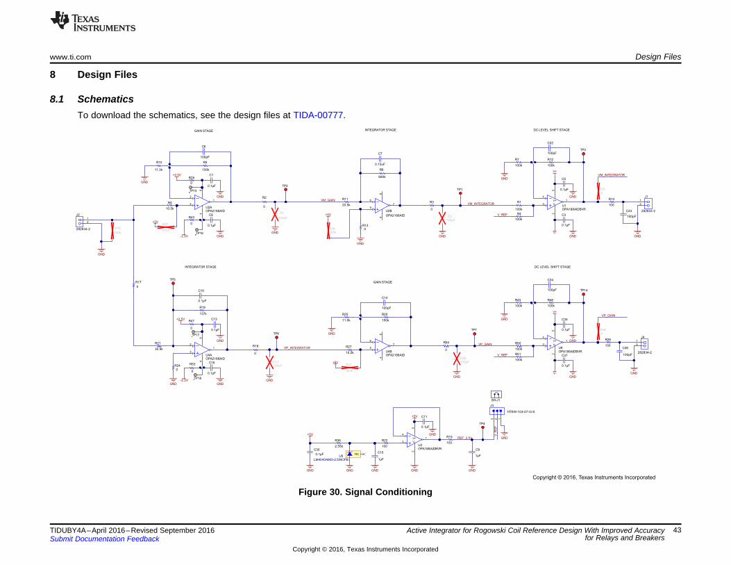
20.5k
R11
GND
GND
GND
GND
4
3
2
1
5
V+
V-
U3OPA188AIDBVR
GND
GND
GND
100pFC2
0.1µF
C5
0.1µF
C3
0.1µF
C11
TP1
TP6
TP7
TP3
VM_INTEGRATOR
VP_INTEGRATORVP_GAIN
1
2
J4
282834-2
GND
GND
V_REF
GNDGND
0.1µF
C30
100pFC12
0
R17
GND
V_R
EF
TP4
REF_2.5V
NCU5
LM4040AIM3-2.5/NOPB
2.55k
R36
GND
1µF
C9
GND
1µF
C15
1
2
J1
282834-2
TP5
100k
R16
GND
1
2
J2
282834-2
GND
GND
0.1µF
C1
0.1µF
C8
TP2
GND
100pF
C4
100pF
C6
4
3
2
1
5
V+
V-U1OPA188AIDBVR
GND
GND
0.1µF
C13
0.1µF
C16
100pF
C14
GND
0
R24
680k
R6
VM_GAIN
300k
R32
100kR34
GND
0R13
300k
R37
INTEGRATOR STAGE
GAIN STAGE
GAIN STAGE INTEGRATOR STAGE DC LEVEL SHIFT STAGE
0
R33
VM_INTEGRATOR
0.15uF
C7
0.1µF
C10
7
5
6
48
U4BOPA2188AID
1
3
2
48
U4AOPA2188AID
7
5
6
48
U2B
OPA2188AID
1
3
2
48
U2AOPA2188AID
100
R15
100
R22
GND
150k
R20
GND
11.0k
R25
100k
R50
100k
R45
100k
R46
GND
100k
R51
GND
GND
0.1µF
C35
0.1µF
C37
TP14
V_REF
4
3
2
1
5
V+
V-
U9OPA188AIDBVR
DC LEVEL SHIFT STAGE
0
R49
VP_GAIN
100pF
C36
100pF
C33
100
R26
0
R2
0
R18
0
R3
100pF
C32
100pF
C34
+5V
+5V
0
R28
0
R47
0
R43
0
R53
+2.5V
+2.5V
+5V
+5V
+5V
-2.5V
-2.5V
V+
V-
137k
R19
150k
R5
10.2k
R27
10.5k
R9
11.3k
R10
30.9k
R21
GND
100pF
C38
0
R54
100k
R7
100k
R12
100k
R1
100k
R4
TP15
TP16
TP17
TP18
V+
V-
SH-J1
100
R14
123
J3
HTSW-103-07-G-S
Copyright © 2016, Texas Instruments Incorporated
www.ti.com Design Files
43TIDUBY4A–April 2016–Revised September 2016Submit Documentation Feedback
Copyright © 2016, Texas Instruments Incorporated
Active Integrator for Rogowski Coil Reference Design With Improved Accuracyfor Relays and Breakers
8 Design Files
8.1 SchematicsTo download the schematics, see the design files at TIDA-00777.
Figure 30. Signal Conditioning
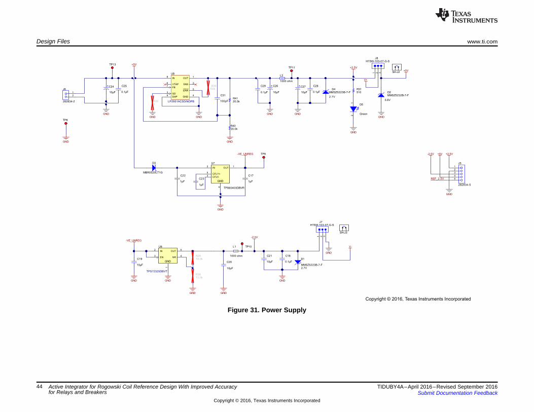
1
2
J6
282834-2
10µF
C24
10µF
C26
0.1µF
C25
0.1µF
C29
GND
10µF
C27
GND GNDGND
1000 ohm
L1
0.1µF
C18
-VE_UNREG
2.7V
D1
MMSZ5223B-7-F
TP13
10µF
C1910µF
C21
D3
MBR0520LT1G
1µF
C22
1µF
C231µF
C17
GND
TP9-VE_UNREG
1
2
3
4
5
J5
282834-5
GND
REF_2.5V
OUT1
IN2
CFLY-3
4
CFLY+5
GND
U7
TPS60403DBVR
GND
10µF
C20
0.1µF
C28
TP8
GND
18.0kR29
10.0kR38
GND
Green
12
D5
GND
GND
IN2
EN3
OUT5
1
GND
NR4
U6
TPS72325DBVT
GND
100pF
C31
GND
0R30
GND
1 2 3
J7HTSW-103-07-G-S
GND
TP11 +2.5V
+2.5V
V-
IN8
ERR5
GND4
VTAP6 SNS 2
DAP9
OUT1
FB7
SD3
U8
LP2951ACSD/NOPB
1000 ohm
L2
GND
100kR39
TP10
+5V
+5V
V+
-2.5V
+5V-2.5V
20.0kR40
20.5kR41
SH-J3
SH-J2
510R31
5.6V
D2MMSZ5232B-7-F
GND
2.7V
D4MMSZ5223B-7-F
1 2 3
J8HTSW-103-07-G-S
Copyright © 2016, Texas Instruments Incorporated
Design Files www.ti.com
44 TIDUBY4A–April 2016–Revised September 2016Submit Documentation Feedback
Copyright © 2016, Texas Instruments Incorporated
Active Integrator for Rogowski Coil Reference Design With Improved Accuracyfor Relays and Breakers
Figure 31. Power Supply

www.ti.com Design Files
45TIDUBY4A–April 2016–Revised September 2016Submit Documentation Feedback
Copyright © 2016, Texas Instruments Incorporated
Active Integrator for Rogowski Coil Reference Design With ImprovedAccuracy for Relays and Breakers
8.2 Bill of MaterialsTo download the bill of materials (BOM), see the design files at TIDA-00777.
8.3 Layout PrintsTo download the layer plots, see the design files at TIDA-00777.
8.4 Altium ProjectTo download the Altium project files, see the design files at TIDA-00777.
8.5 Gerber FilesTo download the Gerber files, see the design files at TIDA-00777.
8.6 Assembly DrawingsTo download the assembly drawings, see the design files at TIDA-00777.
9 References
1. Texas Instruments, Noise Analysis in Operational Amplifier Circuits, Application Report (SLVA043)2. Texas Instruments, WEBENCH® Design Center (http://www.ti.com/webench)
10 About the AuthorsPRAHLAD SUPEDA is a systems engineer at Texas Instruments India, who is responsible for developingreference design solutions for Grid Infrastructure within industrial systems. Prahlad brings to this role hisextensive experience in power electronics, EMC, analog, and mixed signal designs. Prahlad earned hisbachelor of instrumentation and control engineering from Gujarat University, India.
KALLIKUPPA MUNIYAPPA SREENIVASA is a systems architect at Texas Instruments, who isresponsible for developing reference design solutions for the industrial segment. Sreenivasa brings to thisrole his experience in high-speed digital and analog systems design. Sreenivasa earned his bachelor ofelectronics (BE) in electronics and communication engineering (BE-E&C) from VTU, Mysore, India.
AMIT KUMBASI is a systems architect at Texas Instruments Dallas, who is responsible for developingsubsystem solutions for Grid Infrastructure within industrial systems. Amit brings to this role his expertisewith defining products, business development, and board level design using precision analog and mixed-signal devices. He holds a master’s in ECE (Texas Tech) and MBA (University of Arizona). He can bereached at [email protected].
Revision A History www.ti.com
46 TIDUBY4A–April 2016–Revised September 2016Submit Documentation Feedback
Copyright © 2016, Texas Instruments Incorporated
Revision History
Revision A HistoryNOTE: Page numbers for previous revisions may differ from page numbers in the current version.
Changes from Original (July 2016) to A Revision ........................................................................................................... Page
• Changed from preview page............................................................................................................. 1

IMPORTANT NOTICE FOR TI REFERENCE DESIGNS
Texas Instruments Incorporated (‘TI”) reference designs are solely intended to assist designers (“Designer(s)”) who are developing systemsthat incorporate TI products. TI has not conducted any testing other than that specifically described in the published documentation for aparticular reference design.TI’s provision of reference designs and any other technical, applications or design advice, quality characterization, reliability data or otherinformation or services does not expand or otherwise alter TI’s applicable published warranties or warranty disclaimers for TI products, andno additional obligations or liabilities arise from TI providing such reference designs or other items.TI reserves the right to make corrections, enhancements, improvements and other changes to its reference designs and other items.Designer understands and agrees that Designer remains responsible for using its independent analysis, evaluation and judgment indesigning Designer’s systems and products, and has full and exclusive responsibility to assure the safety of its products and compliance ofits products (and of all TI products used in or for such Designer’s products) with all applicable regulations, laws and other applicablerequirements. Designer represents that, with respect to its applications, it has all the necessary expertise to create and implementsafeguards that (1) anticipate dangerous consequences of failures, (2) monitor failures and their consequences, and (3) lessen thelikelihood of failures that might cause harm and take appropriate actions. Designer agrees that prior to using or distributing any systemsthat include TI products, Designer will thoroughly test such systems and the functionality of such TI products as used in such systems.Designer may not use any TI products in life-critical medical equipment unless authorized officers of the parties have executed a specialcontract specifically governing such use. Life-critical medical equipment is medical equipment where failure of such equipment would causeserious bodily injury or death (e.g., life support, pacemakers, defibrillators, heart pumps, neurostimulators, and implantables). Suchequipment includes, without limitation, all medical devices identified by the U.S. Food and Drug Administration as Class III devices andequivalent classifications outside the U.S.Designers are authorized to use, copy and modify any individual TI reference design only in connection with the development of endproducts that include the TI product(s) identified in that reference design. HOWEVER, NO OTHER LICENSE, EXPRESS OR IMPLIED, BYESTOPPEL OR OTHERWISE TO ANY OTHER TI INTELLECTUAL PROPERTY RIGHT, AND NO LICENSE TO ANY TECHNOLOGY ORINTELLECTUAL PROPERTY RIGHT OF TI OR ANY THIRD PARTY IS GRANTED HEREIN, including but not limited to any patent right,copyright, mask work right, or other intellectual property right relating to any combination, machine, or process in which TI products orservices are used. Information published by TI regarding third-party products or services does not constitute a license to use such productsor services, or a warranty or endorsement thereof. Use of the reference design or other items described above may require a license from athird party under the patents or other intellectual property of the third party, or a license from TI under the patents or other intellectualproperty of TI.TI REFERENCE DESIGNS AND OTHER ITEMS DESCRIBED ABOVE ARE PROVIDED “AS IS” AND WITH ALL FAULTS. TI DISCLAIMSALL OTHER WARRANTIES OR REPRESENTATIONS, EXPRESS OR IMPLIED, REGARDING THE REFERENCE DESIGNS OR USE OFTHE REFERENCE DESIGNS, INCLUDING BUT NOT LIMITED TO ACCURACY OR COMPLETENESS, TITLE, ANY EPIDEMIC FAILUREWARRANTY AND ANY IMPLIED WARRANTIES OF MERCHANTABILITY, FITNESS FOR A PARTICULAR PURPOSE, AND NON-INFRINGEMENT OF ANY THIRD PARTY INTELLECTUAL PROPERTY RIGHTS.TI SHALL NOT BE LIABLE FOR AND SHALL NOT DEFEND OR INDEMNIFY DESIGNERS AGAINST ANY CLAIM, INCLUDING BUT NOTLIMITED TO ANY INFRINGEMENT CLAIM THAT RELATES TO OR IS BASED ON ANY COMBINATION OF PRODUCTS ASDESCRIBED IN A TI REFERENCE DESIGN OR OTHERWISE. IN NO EVENT SHALL TI BE LIABLE FOR ANY ACTUAL, DIRECT,SPECIAL, COLLATERAL, INDIRECT, PUNITIVE, INCIDENTAL, CONSEQUENTIAL OR EXEMPLARY DAMAGES IN CONNECTION WITHOR ARISING OUT OF THE REFERENCE DESIGNS OR USE OF THE REFERENCE DESIGNS, AND REGARDLESS OF WHETHER TIHAS BEEN ADVISED OF THE POSSIBILITY OF SUCH DAMAGES.TI’s standard terms of sale for semiconductor products (http://www.ti.com/sc/docs/stdterms.htm) apply to the sale of packaged integratedcircuit products. Additional terms may apply to the use or sale of other types of TI products and services.Designer will fully indemnify TI and its representatives against any damages, costs, losses, and/or liabilities arising out of Designer’s non-compliance with the terms and provisions of this Notice.IMPORTANT NOTICE
Mailing Address: Texas Instruments, Post Office Box 655303, Dallas, Texas 75265Copyright © 2016, Texas Instruments Incorporated