Active Duty Training for Support of Navy s Additive ... · Active Duty Training for Support of...
12
Paper ID #17844 Active Duty Training for Support of Navy’s Additive Manufacturing Strategy Dr. Vukica M. Jovanovic, Old Dominion University Dr. Vukica Jovanovic is an Assistant Professor of Engineering Technology in Mechanical Engineering Technology Program. She holds a Ph.D. from Purdue University in Mechanical Engineering Technol- ogy, focus on Digital Manufacturing. Her research is focused on mechatronics, digital manufacturing, digital thread, cyber physical systems, broadening participation, and engineering education. She is a Co-Director of Mechatronics and Digital Manufacturing Lab at ODU and a lead of Area of Specializa- tion Mechatronics Systems Design. She worked as a Visiting Researcher at Commonwealth Center for Advanced Manufacturing in Disputanta, VA on projects focusing on digital thread and cyber security of manufacturing systems. She has funded research in broadening participation efforts of underrepresented students in STEM funded by Office of Naval Research, focusing on mechatronic pathways. She is part of the ONR project related to the additive manufacturing training of active military. She is also part of the research team that leads the summer camp to nine graders that focus on broadening participation of underrepresented students into STEM (ODU BLAST). Dr. Onur Bilgen, Old Dominion University Dr. Karina Arcaute, Old Dominion University Dr. Karina Arcaute received her BS in Chemical Engineering from the Instituto Tecnologico de Chi- huahua, and her MS (Mechanical Engineering) and PhD (Materials Science and Engineering) from the University of Texas at El Paso. Dr. Arcaute is an Assistant Professor in the Department of STEM Educa- tion and Professional Studies at Old Dominion University in Norfolk, VA. Prof. Michel Albert Audette, Old Dominion University Dr. Michel Albert Audette received the B.Eng. (Electrical) degree from McGill University, in 1986, the M.Eng. degree (Electrical) from Ecole Polytechnique in 1993, and the Ph.D. (Biomedical Engineer- ing) from McGill in 2002, all in Montreal, Canada. His industry experience includes flight simulation from 1986 to 1988, welding automation from 1991 to 1994, neurosurgical navigation (part-time) from 1995-1997, as well as open-source image analysis software from 2008 to 2011. He also did postdoctoral research at the National Institute of Advanced Industrial Science and Technology (AIST) in Tsukuba, Japan from 2001-2005 and at Innovation Center Computer Assisted Surgery (ICCAS) in Leipzig, Ger- many from 2006-2008. He has patents in US and Japan on surgery planning. Since July 2011, he has been employed as assistant professor in Old Dominion University’s Department of Modeling, Simulation and Visualization Engineering. His research interests include medical simulation, medical image analysis, therapy planning, all three with an emphasis on neuro- and orthopedic surgery, as well as other clinical applications of musculoskeletal modeling, in addition to imaging and simulation applications for military well-being. Dr. Anthony W. Dean, Old Dominion University Dr. Anthony W. Dean has had several roles in academia. His previous appointments include Associate Professor of Engineering Technology and as Associate Director of the Institute for Ship Repair, Mainte- nance, and Operations at Old Dominion University (ODU). He is currently on assignment with the Office of the Dean for Sponsored Programs and the Engineering Fundamentals Department, Batten College of Engineering and Technology (BCET) at ODU. His research has focused mostly on control systems (in- tegration and testing) and the reliability and maintainability of complex systems. He has been selected as both a NASA and an ONR Faculty Fellow. He regularly teaches courses in Marine Engineering and in Maintained Systems. Most recently Dr. Dean was on the Headquarters Staff the American Society of Naval Engineers. He received his Ph.D. from the Department of Engineering Management and Systems Engineering, and a B.S. in Nuclear Engineering Technology, from the Batten College of Engineering and Technology at Old Dominion University. Additionally, Dr. Dean received an MBA from the College of c American Society for Engineering Education, 2017
Transcript of Active Duty Training for Support of Navy s Additive ... · Active Duty Training for Support of...
Paper ID #17844
Active Duty Training for Support of Navy’s Additive Manufacturing Strategy
Dr. Vukica M. Jovanovic, Old Dominion University
Dr. Vukica Jovanovic is an Assistant Professor of Engineering Technology in Mechanical EngineeringTechnology Program. She holds a Ph.D. from Purdue University in Mechanical Engineering Technol-ogy, focus on Digital Manufacturing. Her research is focused on mechatronics, digital manufacturing,digital thread, cyber physical systems, broadening participation, and engineering education. She is aCo-Director of Mechatronics and Digital Manufacturing Lab at ODU and a lead of Area of Specializa-tion Mechatronics Systems Design. She worked as a Visiting Researcher at Commonwealth Center forAdvanced Manufacturing in Disputanta, VA on projects focusing on digital thread and cyber security ofmanufacturing systems. She has funded research in broadening participation efforts of underrepresentedstudents in STEM funded by Office of Naval Research, focusing on mechatronic pathways. She is partof the ONR project related to the additive manufacturing training of active military. She is also part ofthe research team that leads the summer camp to nine graders that focus on broadening participation ofunderrepresented students into STEM (ODU BLAST).
Dr. Onur Bilgen, Old Dominion UniversityDr. Karina Arcaute, Old Dominion University
Dr. Karina Arcaute received her BS in Chemical Engineering from the Instituto Tecnologico de Chi-huahua, and her MS (Mechanical Engineering) and PhD (Materials Science and Engineering) from theUniversity of Texas at El Paso. Dr. Arcaute is an Assistant Professor in the Department of STEM Educa-tion and Professional Studies at Old Dominion University in Norfolk, VA.
Prof. Michel Albert Audette, Old Dominion University
Dr. Michel Albert Audette received the B.Eng. (Electrical) degree from McGill University, in 1986,the M.Eng. degree (Electrical) from Ecole Polytechnique in 1993, and the Ph.D. (Biomedical Engineer-ing) from McGill in 2002, all in Montreal, Canada. His industry experience includes flight simulationfrom 1986 to 1988, welding automation from 1991 to 1994, neurosurgical navigation (part-time) from1995-1997, as well as open-source image analysis software from 2008 to 2011. He also did postdoctoralresearch at the National Institute of Advanced Industrial Science and Technology (AIST) in Tsukuba,Japan from 2001-2005 and at Innovation Center Computer Assisted Surgery (ICCAS) in Leipzig, Ger-many from 2006-2008. He has patents in US and Japan on surgery planning. Since July 2011, he hasbeen employed as assistant professor in Old Dominion University’s Department of Modeling, Simulationand Visualization Engineering. His research interests include medical simulation, medical image analysis,therapy planning, all three with an emphasis on neuro- and orthopedic surgery, as well as other clinicalapplications of musculoskeletal modeling, in addition to imaging and simulation applications for militarywell-being.
Dr. Anthony W. Dean, Old Dominion University
Dr. Anthony W. Dean has had several roles in academia. His previous appointments include AssociateProfessor of Engineering Technology and as Associate Director of the Institute for Ship Repair, Mainte-nance, and Operations at Old Dominion University (ODU). He is currently on assignment with the Officeof the Dean for Sponsored Programs and the Engineering Fundamentals Department, Batten College ofEngineering and Technology (BCET) at ODU. His research has focused mostly on control systems (in-tegration and testing) and the reliability and maintainability of complex systems. He has been selectedas both a NASA and an ONR Faculty Fellow. He regularly teaches courses in Marine Engineering andin Maintained Systems. Most recently Dr. Dean was on the Headquarters Staff the American Society ofNaval Engineers. He received his Ph.D. from the Department of Engineering Management and SystemsEngineering, and a B.S. in Nuclear Engineering Technology, from the Batten College of Engineering andTechnology at Old Dominion University. Additionally, Dr. Dean received an MBA from the College of
c©American Society for Engineering Education, 2017

Paper ID #17844
William and Mary. Prior to is academic career Dr. Dean was Director of Operations and Business De-velopment for Clark-Smith Associates, P.C., and served as an Electrician in the US Navy aboard the USSSouth Carolina and the USS Enterprise.
c©American Society for Engineering Education, 2017
Active Duty Training for Support of Navy’s Additive Manufacturing Strategy
Abstract
Additive manufacturing has recently gained the attention of multiple stakeholders, including
those in the advanced manufacturing industry, research and government labs, academia, and the
Navy community. Various efforts within the Navy focus on studying the best way for parts to be
built and repaired for marine and naval vessels. Rapid manufacturing of spare components is
particularly important for sailors, especially while deployed on warships, as they often do not have
timely access to spare parts from the supply chain. For that purpose, a multidisciplinary team of
engineering and education faculty have developed a series of workshops to train on-duty sailors in
designing, testing, reverse engineering, and printing parts needed for their daily operations. The
workshop has modules focused on rapid prototyping, reverse engineering, computer aided design,
material testing, product data management, and product lifecycle management. The Office of
Naval Research Workforce Development program funds this program.
Introduction
Workforce shortages have been reported in the area of advanced manufacturing. Due to this,
several nationwide initiatives have focused on training that will result in an increasingly skilled
labor force, who are capable of working with new technologies (NSTC, 2012; Reeve, 2014). One
such initiatives is focused on the concept of “Making”. Hands-on and project-based concepts are
now available, even by toy makers and book publishers (Brown, 2015; Thomas, 2014), and are
also available in some elementary schools or children’s museums (Bevan, Petrich, & Wilkinson,
2014; Chu, Quek, Bhangaonkar, Ging, & Sridharamurthy, 2015; Cottman, 2015). Rapid
prototyping, although not a very new concept, have recently gained attention in Navy initiatives,
mainly related to the reduction of waiting times in the supply chain while on deployment (Tadjdeh,
2014). The technology has become more affordable to the various stakeholders (Martin, 2015).
Typically, sailors work far away from the regular supply chain, thus, having additive
manufacturing systems on board can reduce downtime and create more efficient maintenance
processes, since long deployments usually cause extended queues for spare components. The U.S.
Navy recently started the Print the Fleet initiative (Tadjdeh, 2014). This is the result of the Chief
of Naval Operations’ Rapid Innovation Cell (CRIC) for the investigation of additive
manufacturing applications in naval operations. Efforts related to the Print the Fleet initiative have
resulted in the installation of multiple 3D printers in various training centers and on ships. During
this effort, different replacement parts have been created, such as oil reservoir caps, medical
supplies, and models of the flight deck.
The current trend is to research applications of metallic printed parts and their integration into
maintenance and repair operations. Another trend in the shipbuilding industry is to move from
paper-based drawings to the digital shipyard. In this way, all parts of a ship or a submarine would
be available as 3D parts. Machine code for any additive manufacturing system can be generated
from such parts. In this way, maintenance and real-time production of metallic and plastic parts,
which go into the print bed of the additive manufacturing system, would be possible. Reverse
engineering might be used on the ships during a deployment, especially if the documentation
cannot be found, or if the original builder is no longer available (Jovanovic & Filipovic, 2011).
Creating the Fleet Maker Initiative
A team of five researchers (the authors) has developed a two-day long workshop for active
duty sailors (Dean, 2016, Audette, 2017). The objectives of the workshop for active duty sailors
are two-fold: the first focuses on building skills needed in daily activities, while the second is
driven by the motivation to expose active duty sailors to opportunities in STEM areas. The team
is composed of faculty employed in the following departments: Engineering Management and
Systems Engineering, Mechanical and Aerospace Engineering, Mechanical Engineering
Technology, STEM Education and Professional Studies, and Modeling, Simulation, and
Visualization Engineering. The primary objectives for the workshop are: 1) focusing on the skills
development related to the workshop concepts (additive manufacturing – AM, computer aided
design – CAD, reverse engineering – RE); 2) fostering of sailors’ STEM knowledge and
professional development, 3) introducing skills needed for opportunities in advanced
manufacturing, and 4) empowering active duty military personnel to solve problems through a
creative design approach. A long-term goal for the project is for active duty personnel to obtain
such skills, so once the 3D printers are deployed to their naval vessels they will have the necessary
skills for efficient on-board maintenance and problem-solving scenarios related to the mechanical
design, reverse engineering, and 3D printing.
Workshop Objectives:
The first objective is to engage active duty military personnel in a Maker environment and
provide them with necessary tools to enhance the skills needed for application of additive
manufacturing for in-situ ship maintenance.
The second objective is to reduce the downtime in naval subsystems, which is related to waiting
for the necessary part to arrive for repair, by providing the Navy with a significant number of
naval personnel trained in 3D printing.
The third objective is to provide an educational workforce development program for active
duty sailors in additive manufacturing to support the Navy’s Print the Fleet initiative that can
be later replicated at other locations.
The Workshop Structure and Learning Activities
The first workshop was delivered to active duty sailors at the end of January 2017. In total, 15
Creating the Fleet Maker workshops will be executed and assessed. Each workshop is designed
for 20 sailors. The content delivered in the workshop is focused on the following STEM areas: a)
computer aided design, b) reverse engineering, c) additive manufacturing, d) solid mechanics and
material testing, and e) product lifecycle management and part retrieval. The following sub-
sections will briefly outline these subject areas grouped under modules.
Module: Dive into Printing
The first module starts with a lecture session giving an overview of the history of rapid
prototyping or additive manufacturing, presenting various names these technologies are also
known by (solid freeform fabrication, direct digital manufacturing, etc.), and an overview of six
of the most currently used AM technologies, describing their commonalities and differences. Each
of the six technologies (stereolithography, photopolymer jetting, electron beam melting, binder
jetting, laser melting, and fused deposition modeling) are described in detail, showing a schematic
of the technology, a video of how it works, as well as presenting advantages, disadvantages, and
uses. Sample parts built using these different technologies are passed around for participants to
examine. Then, the specifics about how the 3D printer can be used (Invent3D Printer) are
presented, including a brief description on its development, the different components, its
functionality. A brief overview of the two main operations are covered: changing the filament and
leveling the board.
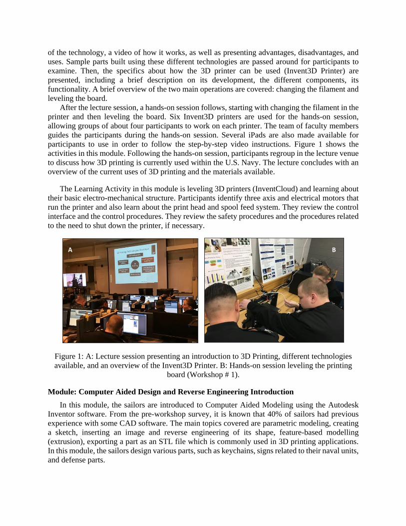
After the lecture session, a hands-on session follows, starting with changing the filament in the
printer and then leveling the board. Six Invent3D printers are used for the hands-on session,
allowing groups of about four participants to work on each printer. The team of faculty members
guides the participants during the hands-on session. Several iPads are also made available for
participants to use in order to follow the step-by-step video instructions. Figure 1 shows the
activities in this module. Following the hands-on session, participants regroup in the lecture venue
to discuss how 3D printing is currently used within the U.S. Navy. The lecture concludes with an
overview of the current uses of 3D printing and the materials available.
The Learning Activity in this module is leveling 3D printers (InventCloud) and learning about
their basic electro-mechanical structure. Participants identify three axis and electrical motors that
run the printer and also learn about the print head and spool feed system. They review the control
interface and the control procedures. They review the safety procedures and the procedures related
to the need to shut down the printer, if necessary.
Figure 1: A: Lecture session presenting an introduction to 3D Printing, different technologies
available, and an overview of the Invent3D Printer. B: Hands-on session leveling the printing
board (Workshop # 1).
Module: Computer Aided Design and Reverse Engineering Introduction
In this module, the sailors are introduced to Computer Aided Modeling using the Autodesk
Inventor software. From the pre-workshop survey, it is known that 40% of sailors had previous
experience with some CAD software. The main topics covered are parametric modeling, creating
a sketch, inserting an image and reverse engineering of its shape, feature-based modelling
(extrusion), exporting a part as an STL file which is commonly used in 3D printing applications.
In this module, the sailors design various parts, such as keychains, signs related to their naval units,
and defense parts.
A B
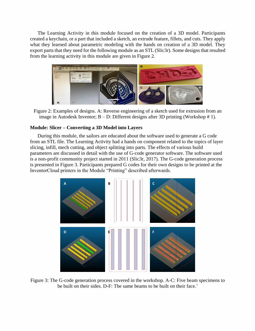
The Learning Activity in this module focused on the creation of a 3D model. Participants
created a keychain, or a part that included a sketch, an extrude feature, fillets, and cuts. They apply
what they learned about parametric modeling with the hands on creation of a 3D model. They
export parts that they need for the following module as an STL (Slic3r). Some designs that resulted
from the learning activity in this module are given in Figure 2.
Figure 2: Examples of designs. A: Reverse engineering of a sketch used for extrusion from an
image in Autodesk Inventor; B – D: Different designs after 3D printing (Workshop # 1).
Module: Slicer – Converting a 3D Model into Layers
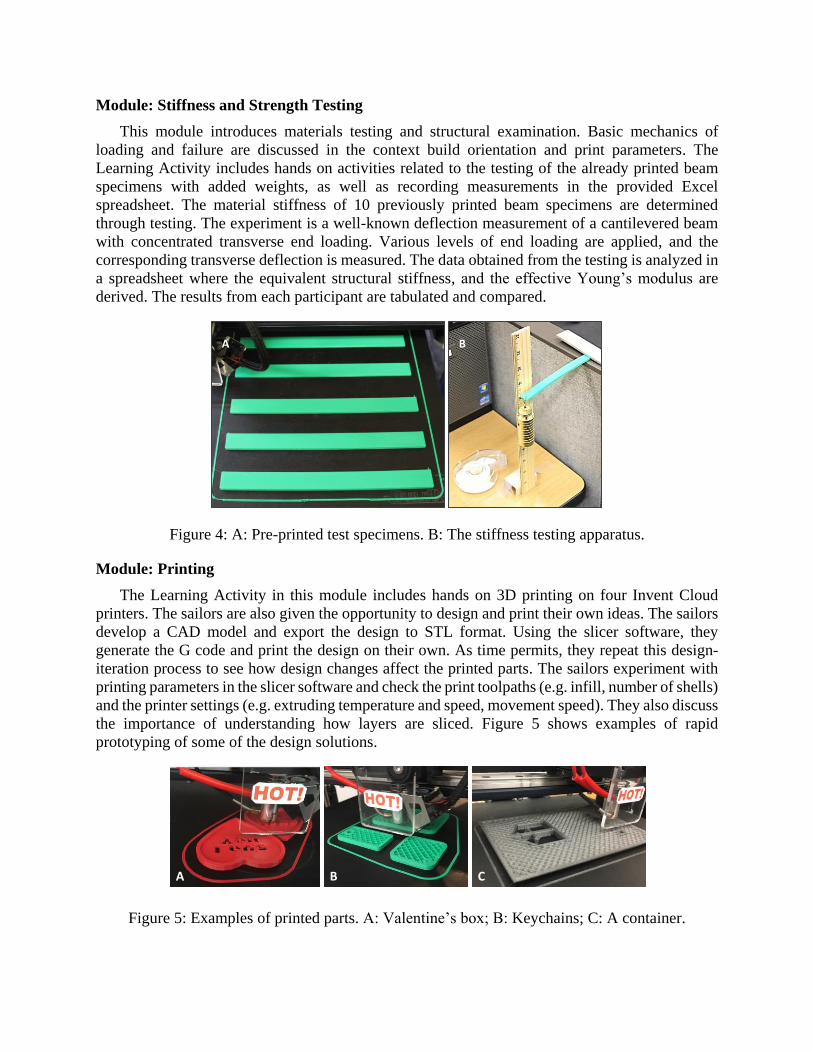
During this module, the sailors are educated about the software used to generate a G code
from an STL file. The Learning Activity had a hands on component related to the topics of layer
slicing, infill, mech cutting, and object splitting into parts. The effects of various build
parameters are discussed in detail with the use of G-code generator software. The software used
is a non-profit community project started in 2011 (Slic3r, 2017). The G-code generation process
is presented in Figure 3. Participants prepared G codes for their own designs to be printed at the
InventorCloud printers in the Module “Printing” described afterwards.
Figure 3: The G-code generation process covered in the workshop. A-C: Five beam specimens to
be built on their sides. D-F: The same beams to be built on their face.’
B CA
E FD
Module: Stiffness and Strength Testing
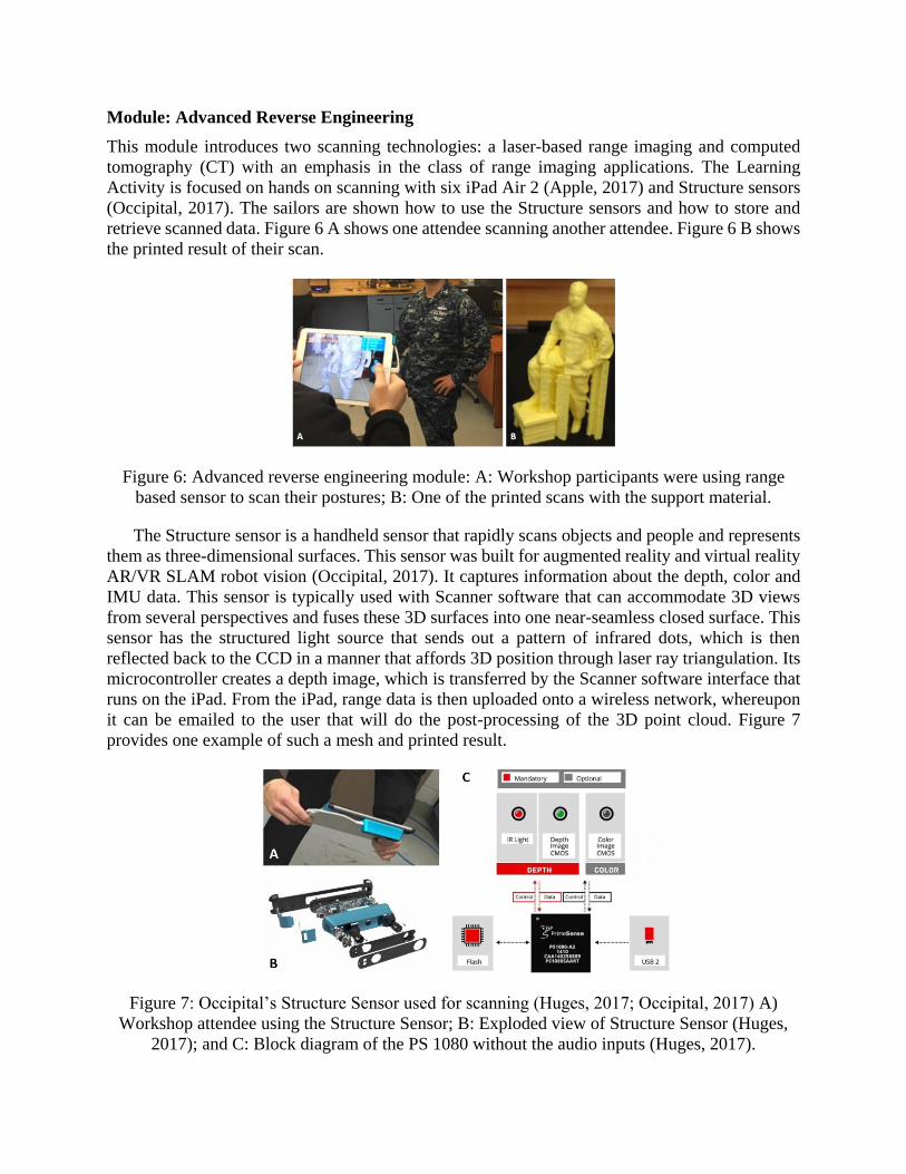
This module introduces materials testing and structural examination. Basic mechanics of
loading and failure are discussed in the context build orientation and print parameters. The
Learning Activity includes hands on activities related to the testing of the already printed beam
specimens with added weights, as well as recording measurements in the provided Excel
spreadsheet. The material stiffness of 10 previously printed beam specimens are determined
through testing. The experiment is a well-known deflection measurement of a cantilevered beam
with concentrated transverse end loading. Various levels of end loading are applied, and the
corresponding transverse deflection is measured. The data obtained from the testing is analyzed in
a spreadsheet where the equivalent structural stiffness, and the effective Young’s modulus are
derived. The results from each participant are tabulated and compared.
Figure 4: A: Pre-printed test specimens. B: The stiffness testing apparatus.
Module: Printing
The Learning Activity in this module includes hands on 3D printing on four Invent Cloud
printers. The sailors are also given the opportunity to design and print their own ideas. The sailors
develop a CAD model and export the design to STL format. Using the slicer software, they
generate the G code and print the design on their own. As time permits, they repeat this design-
iteration process to see how design changes affect the printed parts. The sailors experiment with
printing parameters in the slicer software and check the print toolpaths (e.g. infill, number of shells)
and the printer settings (e.g. extruding temperature and speed, movement speed). They also discuss
the importance of understanding how layers are sliced. Figure 5 shows examples of rapid
prototyping of some of the design solutions.
Figure 5: Examples of printed parts. A: Valentine’s box; B: Keychains; C: A container.
A B
A B C
Module: Advanced Reverse Engineering
This module introduces two scanning technologies: a laser-based range imaging and computed
tomography (CT) with an emphasis in the class of range imaging applications. The Learning
Activity is focused on hands on scanning with six iPad Air 2 (Apple, 2017) and Structure sensors
(Occipital, 2017). The sailors are shown how to use the Structure sensors and how to store and
retrieve scanned data. Figure 6 A shows one attendee scanning another attendee. Figure 6 B shows
the printed result of their scan.
Figure 6: Advanced reverse engineering module: A: Workshop participants were using range
based sensor to scan their postures; B: One of the printed scans with the support material.
The Structure sensor is a handheld sensor that rapidly scans objects and people and represents
them as three-dimensional surfaces. This sensor was built for augmented reality and virtual reality
AR/VR SLAM robot vision (Occipital, 2017). It captures information about the depth, color and
IMU data. This sensor is typically used with Scanner software that can accommodate 3D views
from several perspectives and fuses these 3D surfaces into one near-seamless closed surface. This
sensor has the structured light source that sends out a pattern of infrared dots, which is then
reflected back to the CCD in a manner that affords 3D position through laser ray triangulation. Its
microcontroller creates a depth image, which is transferred by the Scanner software interface that
runs on the iPad. From the iPad, range data is then uploaded onto a wireless network, whereupon
it can be emailed to the user that will do the post-processing of the 3D point cloud. Figure 7
provides one example of such a mesh and printed result.
Figure 7: Occipital’s Structure Sensor used for scanning (Huges, 2017; Occipital, 2017) A)
Workshop attendee using the Structure Sensor; B: Exploded view of Structure Sensor (Huges,
2017); and C: Block diagram of the PS 1080 without the audio inputs (Huges, 2017).
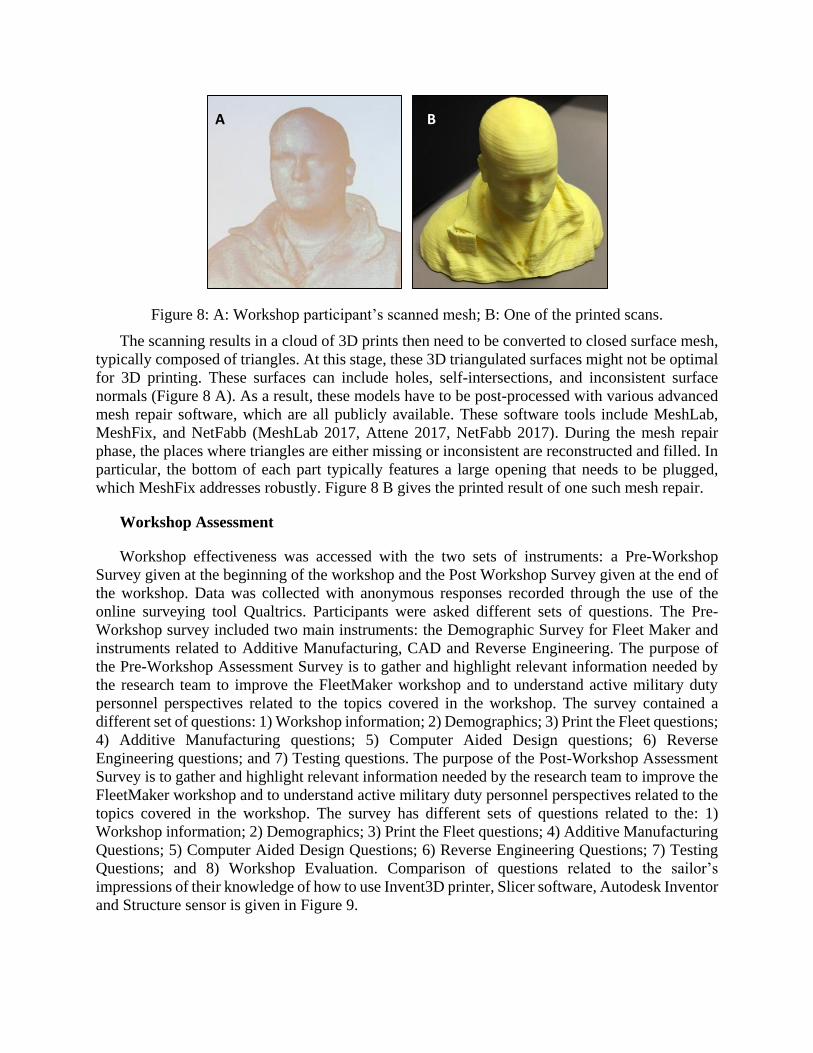
Figure 8: A: Workshop participant’s scanned mesh; B: One of the printed scans.
The scanning results in a cloud of 3D prints then need to be converted to closed surface mesh,
typically composed of triangles. At this stage, these 3D triangulated surfaces might not be optimal
for 3D printing. These surfaces can include holes, self-intersections, and inconsistent surface
normals (Figure 8 A). As a result, these models have to be post-processed with various advanced
mesh repair software, which are all publicly available. These software tools include MeshLab,
MeshFix, and NetFabb (MeshLab 2017, Attene 2017, NetFabb 2017). During the mesh repair
phase, the places where triangles are either missing or inconsistent are reconstructed and filled. In
particular, the bottom of each part typically features a large opening that needs to be plugged,
which MeshFix addresses robustly. Figure 8 B gives the printed result of one such mesh repair.
Workshop Assessment
Workshop effectiveness was accessed with the two sets of instruments: a Pre-Workshop
Survey given at the beginning of the workshop and the Post Workshop Survey given at the end of
the workshop. Data was collected with anonymous responses recorded through the use of the
online surveying tool Qualtrics. Participants were asked different sets of questions. The Pre-
Workshop survey included two main instruments: the Demographic Survey for Fleet Maker and
instruments related to Additive Manufacturing, CAD and Reverse Engineering. The purpose of
the Pre-Workshop Assessment Survey is to gather and highlight relevant information needed by
the research team to improve the FleetMaker workshop and to understand active military duty
personnel perspectives related to the topics covered in the workshop. The survey contained a
different set of questions: 1) Workshop information; 2) Demographics; 3) Print the Fleet questions;
4) Additive Manufacturing questions; 5) Computer Aided Design questions; 6) Reverse
Engineering questions; and 7) Testing questions. The purpose of the Post-Workshop Assessment
Survey is to gather and highlight relevant information needed by the research team to improve the
FleetMaker workshop and to understand active military duty personnel perspectives related to the
topics covered in the workshop. The survey has different sets of questions related to the: 1)
Workshop information; 2) Demographics; 3) Print the Fleet questions; 4) Additive Manufacturing
Questions; 5) Computer Aided Design Questions; 6) Reverse Engineering Questions; 7) Testing
Questions; and 8) Workshop Evaluation. Comparison of questions related to the sailor’s
impressions of their knowledge of how to use Invent3D printer, Slicer software, Autodesk Inventor
and Structure sensor is given in Figure 9.
A B
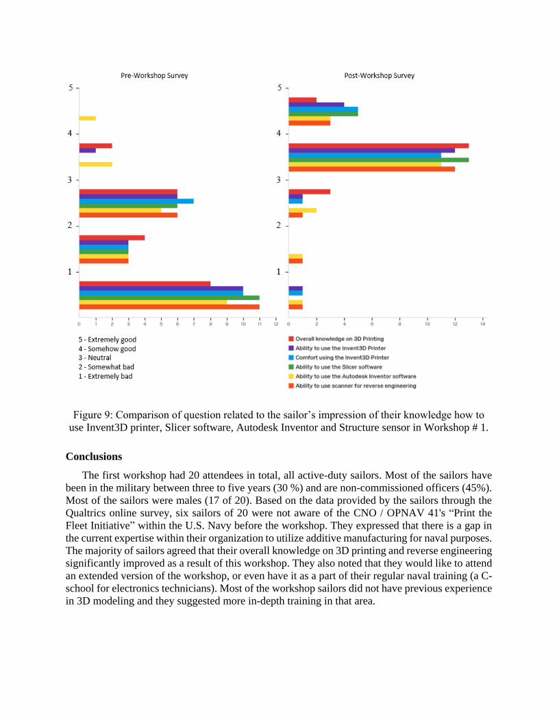
Figure 9: Comparison of question related to the sailor’s impression of their knowledge how to
use Invent3D printer, Slicer software, Autodesk Inventor and Structure sensor in Workshop # 1.
Conclusions
The first workshop had 20 attendees in total, all active-duty sailors. Most of the sailors have
been in the military between three to five years (30 %) and are non-commissioned officers (45%).
Most of the sailors were males (17 of 20). Based on the data provided by the sailors through the
Qualtrics online survey, six sailors of 20 were not aware of the CNO / OPNAV 41's “Print the
Fleet Initiative” within the U.S. Navy before the workshop. They expressed that there is a gap in
the current expertise within their organization to utilize additive manufacturing for naval purposes.
The majority of sailors agreed that their overall knowledge on 3D printing and reverse engineering
significantly improved as a result of this workshop. They also noted that they would like to attend
an extended version of the workshop, or even have it as a part of their regular naval training (a C-
school for electronics technicians). Most of the workshop sailors did not have previous experience
in 3D modeling and they suggested more in-depth training in that area.
Acknowledgments
Work presented in this paper is supported by the Office of Naval Research Grant #12118989.
References
Apple. (2017). iPad Air 2. from http://www.apple.com/ipad-air-2/
[Applied Systems & Technology Transfer]. (2015, July 24). INVENT3D Instructions – Changing
Filament. [Video File]. Retrieved from https://youtu.be/GkhGFjlLo9Y .
[Applied Systems & Technology Transfer]. (2015, July 24). INVENT3D Instructions – Print Board
Leveling. [Video File]. Retrieved from https://youtu.be/t5xmp9knYew.
[Applied Systems & Technology Transfer]. (2015, July 24). INVENT3D Instructions – Z axis Calibration.
[Video File]. Retrieved from https://youtu.be/jwzYRii9fM0.
Audette, M. A., Jovanovic, V., Bilgen, O., Arcaute, K., Dean, A. W. (2017). Creating the Fleet Maker: a
3D Printing-centered STEM Learning Environment for the Stimulation of Innovative Thinking
and Empowerment of Sailors. Paper presented at the ASNE Day 2017 - Technology, Systems &
Ships, Arlington, VA.
Attene M (2017), MeshFix 2.1, https://github.com/MarcoAttene/MeshFix-V2.1 .
Bevan, B., Petrich, M., & Wilkinson, K. (2014). TINKERING Is Serious PLAY. Educational Leadership,
72(4), 28.
Brown, A. (2015). 3D Printing in Instructional Settings: Identifying a Curricular Hierarchy of Activities.
TechTrends: Linking Research & Practice to Improve Learning, 59(5), 16-24. doi:
10.1007/s11528-015-0887-1
Chu, S. L., Quek, F., Bhangaonkar, S., Ging, A. B., & Sridharamurthy, K. (2015). Making the Maker: A
Means-to-an-Ends approach to nurturing the Maker mindset in elementary-aged children.
International Journal of Child-Computer Interaction. doi: 10.1016/j.ijcci.2015.08.002
Cottman, M. H. (2015). Minority Male Makers Program Introduces Youth To STEM Opportunities, p. 11.
Retrieved from http://themadisontimes.themadent.com/article/new-program-trains-young-
minority-males-stem-field/
Dean, A. W., Jovanovic, V., Arcaute, K., Bilgen, O., Audette, M., Bawab, S., Tomovic, M., McKenzie,
R., Chaturvedi, S. (2016). Creating the Fleet Maker: An Informal STEM Learning Environment
to Stimulate Innovative Thinking, Broaden Participation in STEM, and Empower All Sailors to
Become Aware of the Possibilities Available through STEM Learning: Office of Naval Research
- Navy and Marine Corps Science, Technology, Engineering & Mathematics (STEM) Education,
Outreach and Workforce Program
Eugene, B. (2013). Slic3r 0.9.8 v. KISSlicer 1.0.9.7. from https://www.youtube.com/watch?v=HmM_f3v-
zh0
Huges, M. (2017). Teardown Tuesday: Occipital 3D Structure Sensor. All About Circuits. Retrieved
February 5, 2017, from http://www.allaboutcircuits.com/news/teardown-tuesday-occipital-3d-
structure-sensor/
Jovanovic, V., & Filipovic, S. (2011). Reverse Engineering as a Product Design Tool. Paper presented at
the XV International Scientific Conference on Industrial Systems IS `11, Novi Sad, Serbia.
Martin, L. (2015). The Promise of the Maker Movement for Education. Journal of Pre-College
Engineering Education Research, 5(1), 30-39. doi: 10.7771/2157-9288.1099
MeshLab (2017), http://www.meshlab.net/ .
NetFabb (2017), https://www.netfabb.com/ .
NSTC. (2012). A National Strategic Plan for Advanced Manufacturing: National Science and Technology
Council.
Occipital, I. (2017). Structure Sensor. from https://structure.io/
Reeve, E. M. (2014). STEM Thinking! (cover story). Technology & Engineering Teacher, 74(4), 8.

Sung, Y. (2017). THE SOLIDOODLE. Retrieved February 5, 2017, from
http://holdernessshtysung.weebly.com/about-the-solidoodle.html
Tadjdeh, Y. (2014). Navy Beefs Up 3D Printing Efforts With New 'Print the Fleet' Program. National
Defense, 99(731), 24-26.
Thomas, A. (2014). Making makers. [electronic resource] : kids, tools, and the future of innovation:
[Place of publication not identified : publisher not identified], 2014.