
Acti9 Launch Catalogue
124
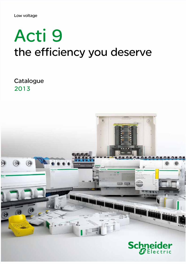
Acti 9 the efficiency you deserve Catalogue 2013 Low voltage
-
Upload
john-lorenzo -
Category
Documents
-
view
667 -
download
0
description
Acti 9
Transcript of Acti9 Launch Catalogue
7/16/2019 Acti9 Launch Catalogue
http://slidepdf.com/reader/full/acti9-launch-catalogue 1/124
Acti 9the efficiency you deserve
Catalogue
2013
Low voltage
7/16/2019 Acti9 Launch Catalogue
http://slidepdf.com/reader/full/acti9-launch-catalogue 2/124
2
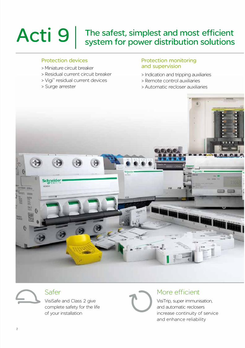
The safest, simplest and most efficientsystem for power distribution solutionsActi 9
Safer VisiSafe and Class 2 give
complete safety for the life
of your installation
More efficient VisiTrip, super immunisation,
and automatic reclosers
increase continuity of service
and enhance reliability
Protection devices Protection monitoringand supervision> Miniature circuit breaker
> Residual current circuit breaker
> Vigi™ residual current devices
> Surge arrester
> Indication and tripping auxiliaries
> Remote control auxiliaries
> Automatic recloser auxiliaries
7/16/2019 Acti9 Launch Catalogue
http://slidepdf.com/reader/full/acti9-launch-catalogue 3/124
3
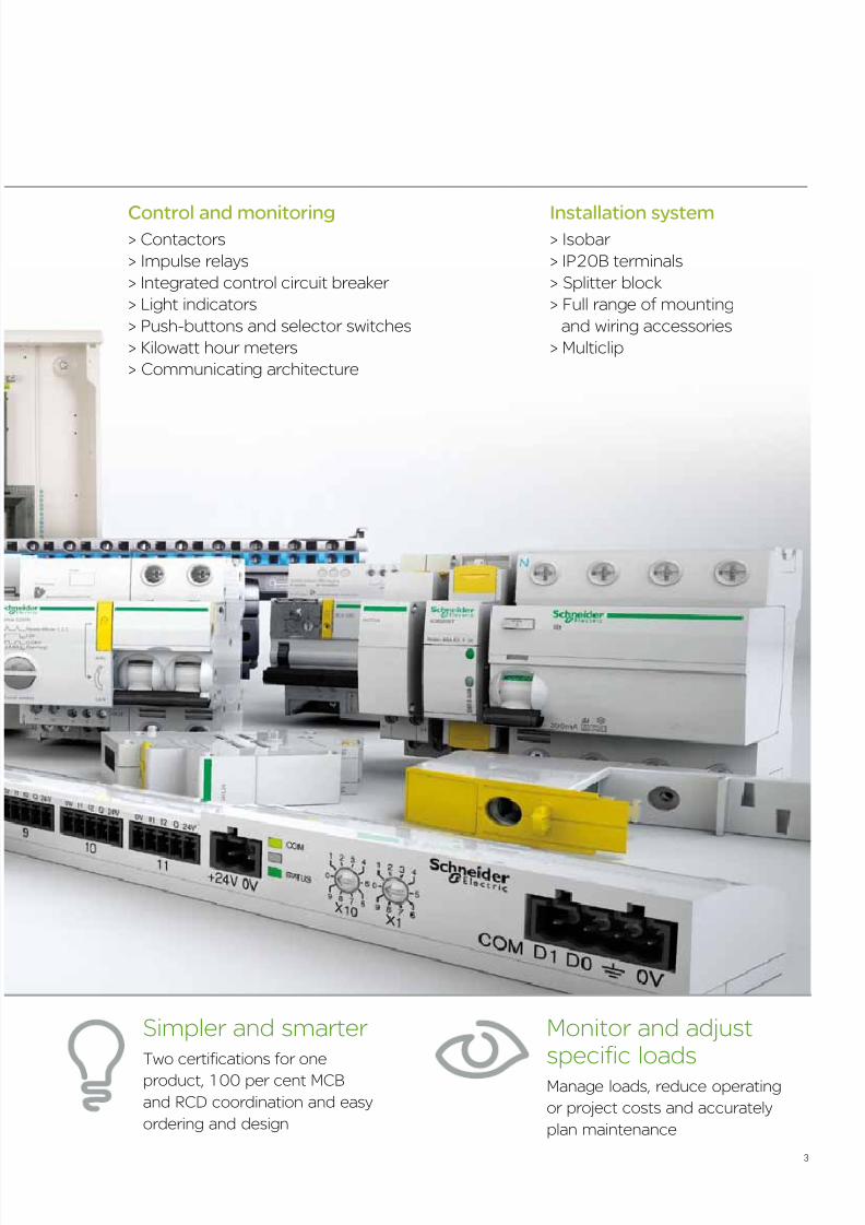
Simpler and smarter Two certifications for one
product, 100 per cent MCB
and RCD coordination and easy
ordering and design
Control and monitoring> Contactors
> Impulse relays
> Integrated control circuit breaker
> Light indicators
> Push-buttons and selector switches
> Kilowatt hour meters
> Communicating architecture
Installation system> Isobar
> IP20B terminals
> Splitter block
> Full range of mounting
and wiring accessories
> Multiclip
Monitor and adjustspecific loadsManage loads, reduce operating
or project costs and accurately
plan maintenance
7/16/2019 Acti9 Launch Catalogue
http://slidepdf.com/reader/full/acti9-launch-catalogue 4/124
4
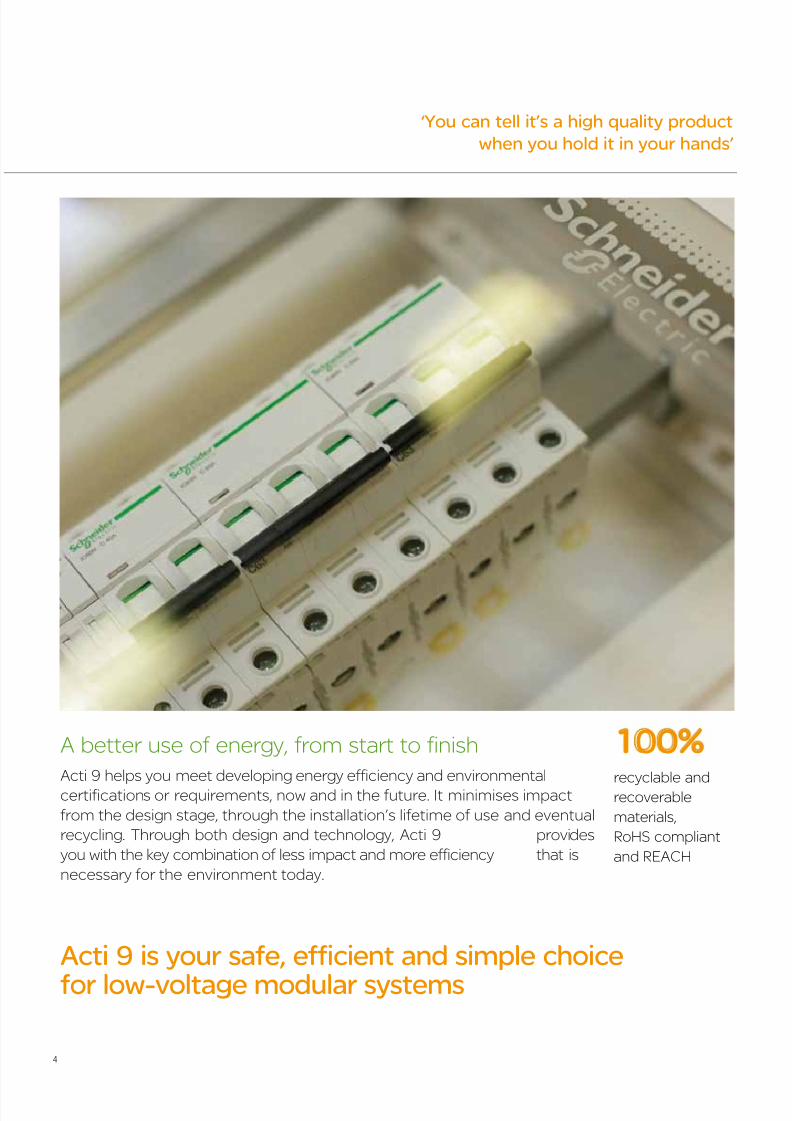
‘You can tell it’s a high quality product
when you hold it in your hands’
Acti 9 helps you meet developing energy efficiency and environmental
certifications or requirements, now and in the future. It minimises impact
from the design stage, through the installation’s lifetime of use and eventual
recycling. Through both design and technology, Acti 9 provides
you with the key combination of less impact and more efficiency that is
necessary for the environment today.
A better use of energy, from start to finish
recyclable andrecoverable
materials,
RoHS compliant
and REACH
Acti 9 is your safe, efficient and simple choice
for low-voltage modular systems
100%
7/16/2019 Acti9 Launch Catalogue
http://slidepdf.com/reader/full/acti9-launch-catalogue 5/124
5
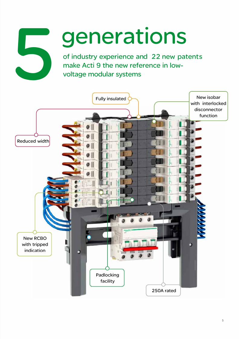
5 of industry experience and 22 new patentsmake Acti 9 the new reference in low-
voltage modular systems
generations
Padlocking
facility
Reduced width
Fully insulated New isobar
with interlocked
disconnector
function
New RCBOwith tripped
indication
250A rated
7/16/2019 Acti9 Launch Catalogue
http://slidepdf.com/reader/full/acti9-launch-catalogue 6/124
6
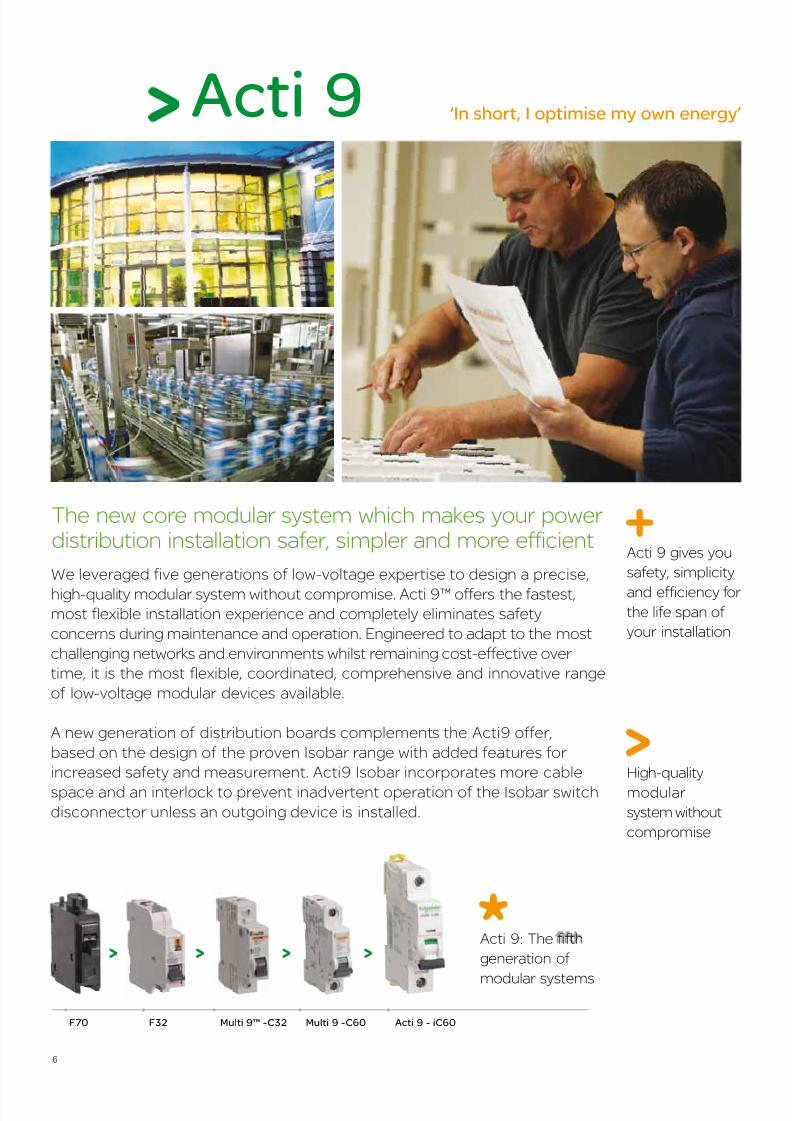
Acti 9
We leveraged five generations of low-voltage expertise to design a precise,
high-quality modular system without compromise. Acti 9™ offers the fastest,
most flexible installation experience and completely eliminates safety
concerns during maintenance and operation. Engineered to adapt to the most
challenging networks and environments whilst remaining cost-effective over
time, it is the most flexible, coordinated, comprehensive and innovative range
of low-voltage modular devices available.
A new generation of distribution boards complements the Acti9 offer,
based on the design of the proven Isobar range with added features for
increased safety and measurement. Acti9 Isobar incorporates more cable
space and an interlock to prevent inadvertent operation of the Isobar switch
disconnector unless an outgoing device is installed.
High-quality
modular
system without
compromise
The new core modular system which makes your power distribution installation safer, simpler and more efficient
‘In short, I optimise my own energy’
Acti 9 - iC60F70 F32 Multi 9™ -C32 Multi 9 -C60
Acti 9: The fifth
generation of
modular systems
Acti 9 gives you
safety, simplicity
and efficiency for the life span of
your installation

7/16/2019 Acti9 Launch Catalogue
http://slidepdf.com/reader/full/acti9-launch-catalogue 7/124
7
safe for installers and
users in the most
severe environments
Best choice for industrial
and commercial
buildings
Safest operation guaranteed even inthe most demanding environmentsSafe
100%
Designed for safety, even in the most demanding environments
Safety matters most and Acti 9 Isobar gives you, your customers and their installations the
highest level of protection available. It guarantees 100 per cent safe operation and maintenance
for you and your customers. Its international certifications and numerous protection innovationsallow Acti 9 to exceed even the most demanding requirements to give you total safety during
maintenance, for the lifetime of your installation.
Delivers complete industry-approved protection
Acti 9 is ully tested, approved and certifed by national and international third parties.
It guarantees that your installation is sae and compliant with all relevant saety standards
and demonstrates to your customers that you use industry-approved materials and
best practices.
Comprehensive certification
7/16/2019 Acti9 Launch Catalogue
http://slidepdf.com/reader/full/acti9-launch-catalogue 8/124
8
part of isobar
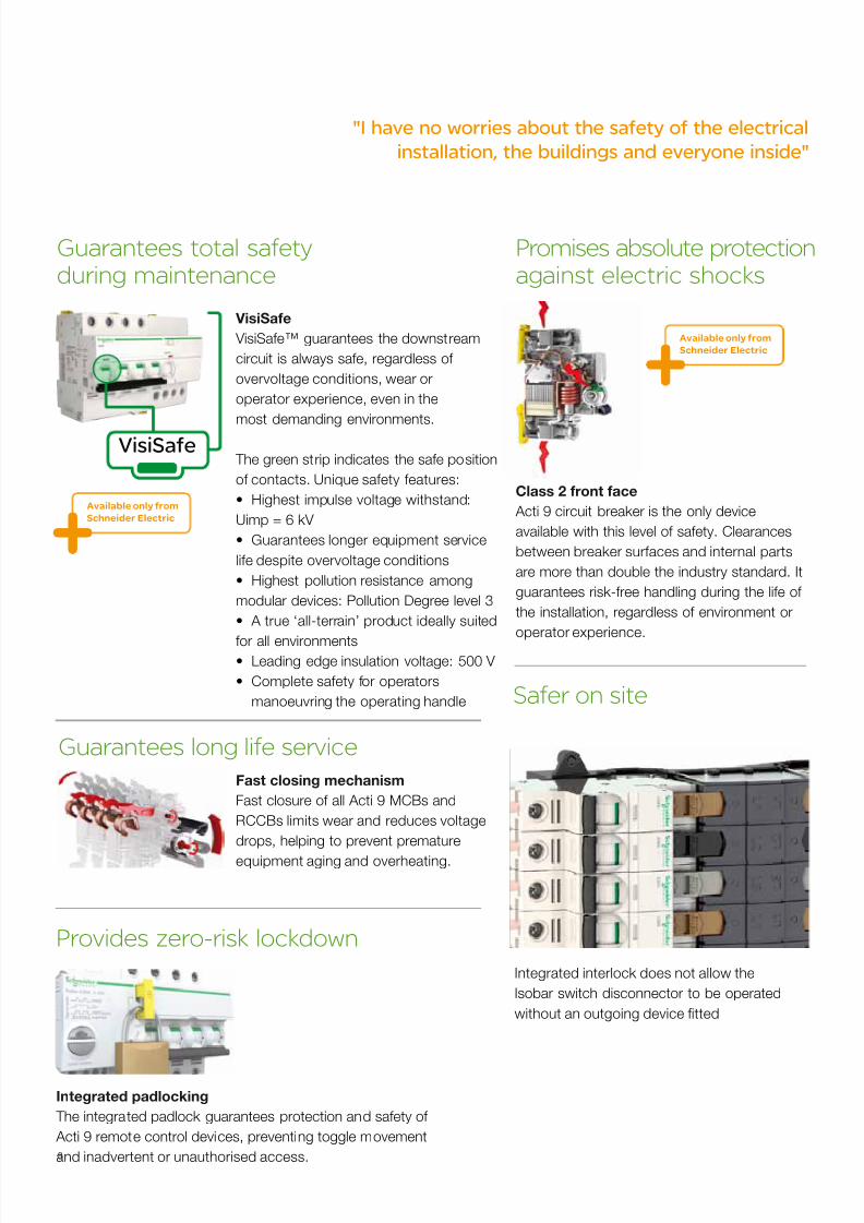
"I have no worries about the safety of the electrical
installation, the buildings and everyone inside"
VisiSafe
Guarantees total safetyduring maintenance
Fast closing mechanism
Fast closure o all Acti 9 MCBs and
RCCBs limits wear and reduces voltage
drops, helping to prevent premature
equipment aging and overheating.
Integrated interlock does not allow the
Isobar switch disconnector to be operated
without an outgoing device ftted
Guarantees long life service
Safer on site
Integrated padlocking
The integrated padlock guarantees protection and saety o
Acti 9 remote control devices, preventing toggle movement
and inadvertent or unauthorised access.
Provides zero-risk lockdown
Class 2 front face
Acti 9 circuit breaker is the only device
available with this level o saety. Clearances
between breaker suraces and internal parts
are more than double the industry standard. It
guarantees risk-ree handling during the lie o
the installation, regardless o environment or
operator experience.
Promises absolute protectionagainst electric shocks
VisiSafe
VisiSae™ guarantees the downstream
circuit is always sae, regardless o
overvoltage conditions, wear or
operator experience, even in the
most demanding environments.
The green strip indicates the sae position
o contacts. Unique saety eatures:
• Highest impulse voltage withstand:
Uimp = 6 kV
• Guarantees longer equipment service
lie despite overvoltage conditions
• Highest pollution resistance among
modular devices: Pollution Degree level 3
• A true ‘all-terrain’ product ideally suited
or all environments• Leading edge insulation voltage: 500 V
• Complete safety for operators
manoeuvring the operating handle
Available only from
Schneider Electric
Available only from
Schneider Electric

7/16/2019 Acti9 Launch Catalogue
http://slidepdf.com/reader/full/acti9-launch-catalogue 9/124
9
Acti 9 simplifies final distribution operations in buildings and industrial facilities, giving you the
right solution with the right technical characteristics for every application. As new installation
standards emerge or building requirements are modified, Acti 9 can easily scale to meet
your needs. It’s a flexible, open system with all-in-one, integrated components which can
communicate with any building management system.
Simple and smart
The right solution for every application
7/16/2019 Acti9 Launch Catalogue
http://slidepdf.com/reader/full/acti9-launch-catalogue 10/124
10
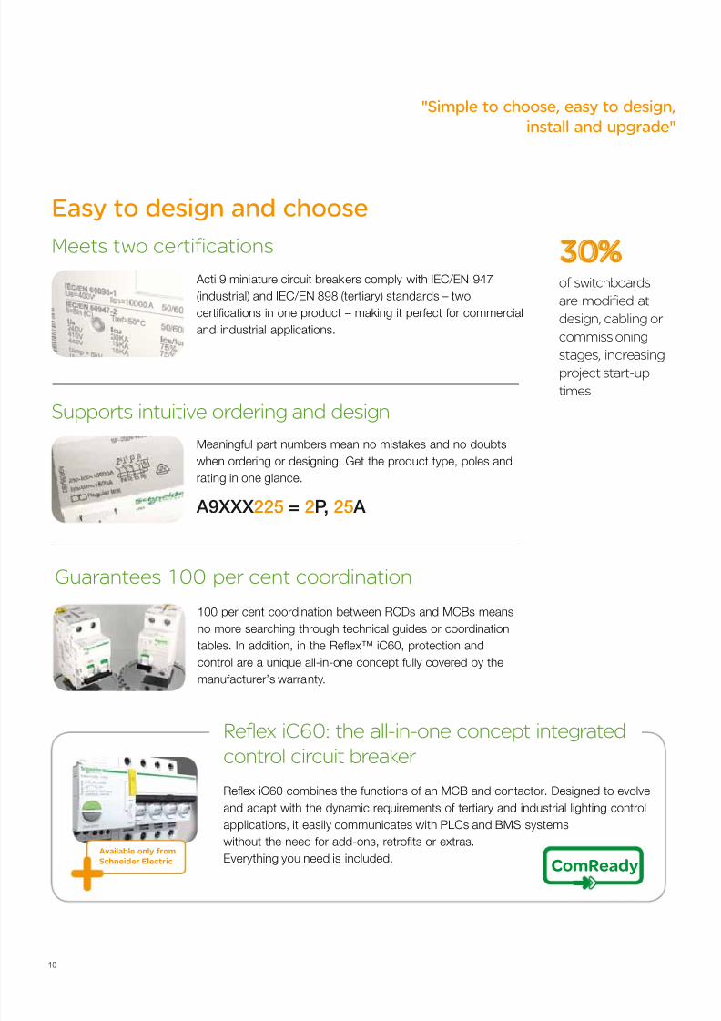
100 per cent coordination between RCDs and MCBs means
no more searching through technical guides or coordination
tables. In addition, in the Reex™ iC60, protection and
control are a unique all-in-one concept ully covered by the
manufacturer’s warranty.
Guarantees 100 per cent coordination
Acti 9 miniature circuit breakers comply with IEC/EN 947
(industrial) and IEC/EN 898 (tertiary) standards – two
certifcations in one product – making it perect or commercial
and industrial applications.
Meets two certifications
Meaningul part numbers mean no mistakes and no doubts
when ordering or designing. Get the product type, poles and
rating in one glance.
Supports intuitive ordering and design
Easy to design and choose
of switchboards
are modified at
design, cabling or
commissioning
stages, increasingproject start-up
times
30%
A9XXX225 = 2P, 25 A
Reex iC60 combines the functions of an MCB and contactor. Designed to evolve
and adapt with the dynamic requirements o tertiary and industrial lighting control
applications, it easily communicates with PLCs and BMS systems
without the need or add-ons, retrofts or extras.
Everything you need is included.
Reflex iC60: the all-in-one concept integrated
control circuit breaker
Available only from
Schneider Electric ComReady
"Simple to choose, easy to design,
install and upgrade"
7/16/2019 Acti9 Launch Catalogue
http://slidepdf.com/reader/full/acti9-launch-catalogue 11/124
11
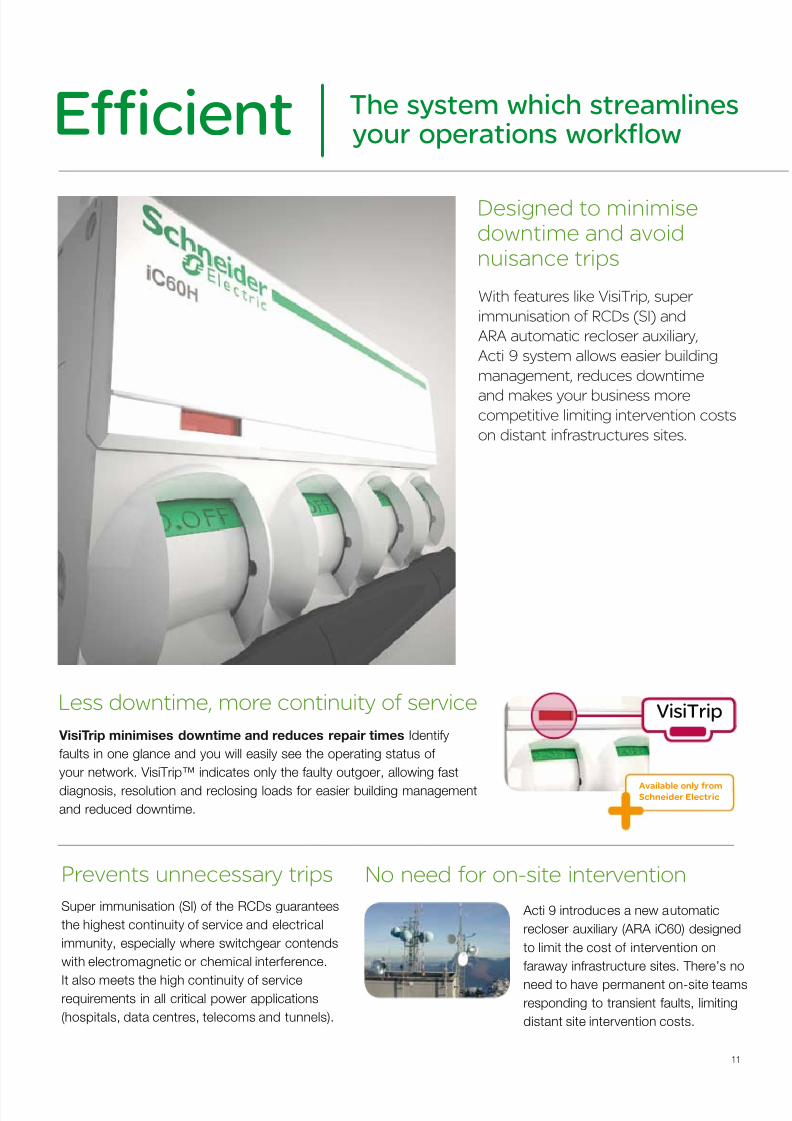
With features like VisiTrip, super
immunisation of RCDs (SI) and
ARA automatic recloser auxiliary,
Acti 9 system allows easier building
management, reduces downtime
and makes your business morecompetitive limiting intervention costs
on distant infrastructures sites.
Designed to minimisedowntime and avoidnuisance trips
The system which streamlinesyour operations workflowEfficient
VisiTrip minimises downtime and reduces repair times Identiy
aults in one glance and you will easily see the operating status o
your network. VisiTrip™ indicates only the aulty outgoer, allowing ast
diagnosis, resolution and reclosing loads or easier building management
and reduced downtime.
Less downtime, more continuity of service
Super immunisation (SI) o the RCDs guarantees
the highest continuity o service and electrical
immunity, especially where switchgear contends
with electromagnetic or chemical intererence.
It also meets the high continuity o servicerequirements in all critical power applications
(hospitals, data centres, telecoms and tunnels).
Prevents unnecessary trips
Acti 9 introduces a new automatic
recloser auxiliary (ARA iC60) designed
to limit the cost o intervention on
faraway infrastructure sites. There’s no
need to have permanent on-site teams
responding to transient aults, limiting
distant site intervention costs.
No need for on-site intervention
Available only fromSchneider Electric
VisiTrip
7/16/2019 Acti9 Launch Catalogue
http://slidepdf.com/reader/full/acti9-launch-catalogue 12/124
12
time saved on
design and
installation
coordination
between MCB
and actuator
15%100%
"Everything is simpler with Acti 9. Whatever
the application, I have no second thoughts"
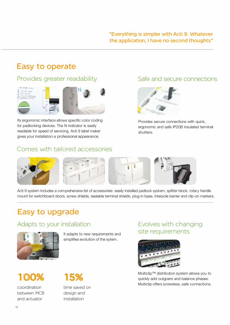
Provides secure connections with quick,
ergonomic and safe IP20B insulated terminal
shutters.
Safe and secure connections
Acti 9 system includes a comprehensive list of accessories: easily installed padlock system, splitter block, rotary handle
mount for switchboard doors, screw shields, sealable terminal shields, plug-in base, interpole barrier and clip-on markers.
Comes with tailored accessories
It adapts to new requirements and
simplifes evolution o the sytem.
Easy to upgrade
Adapts to your installation
Its ergonomic interace allows specifc color coding
or padlocking devices. The N indicator is easily
readable or speed o servicing. Acti 9 label maker
gives your installation a proessional appearance.
Provides greater readability
Easy to operate
Multiclip™ distribution system allows you to
quickly add outgoers and balance phases.
Multiclip oers screwless, sae connections.
Evolves with changingsite requirements
7/16/2019 Acti9 Launch Catalogue
http://slidepdf.com/reader/full/acti9-launch-catalogue 13/124
13
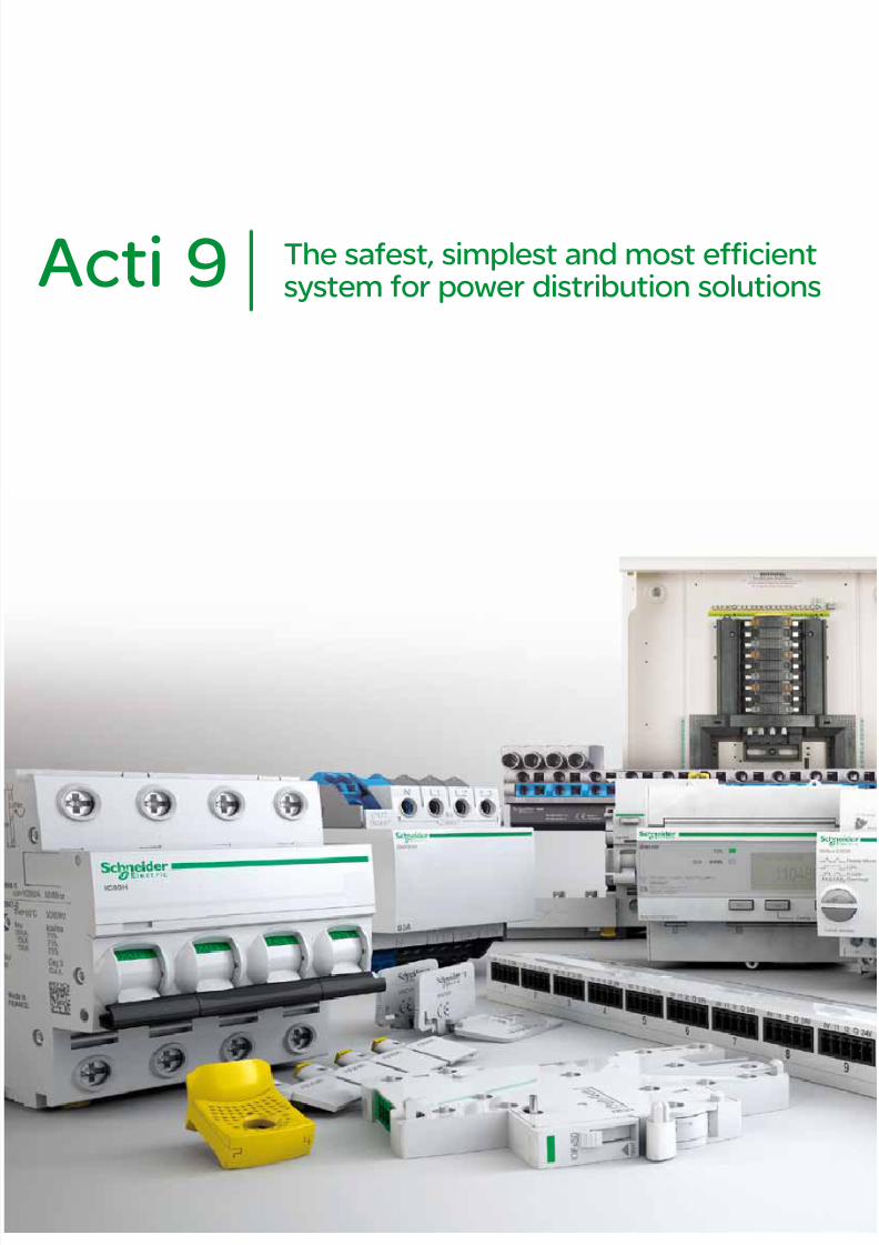
The safest, simplest and most efficientsystem for power distribution solutionsActi 9
7/16/2019 Acti9 Launch Catalogue
http://slidepdf.com/reader/full/acti9-launch-catalogue 14/124
14
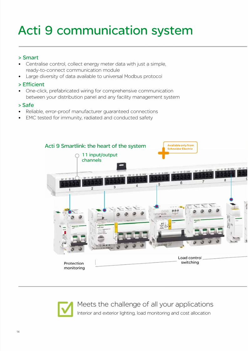
> Smart• Centralise control, collect energy meter data with just a simple,
ready-to-connect communication module
• Large diversity of data available to universal Modbus protocol
> Efficient• One-click, prefabricated wiring for comprehensive communication
between your distribution panel and any facility management system
> Safe• Reliable, error-proof manufacturer guaranteed connections
• EMC tested for immunity, radiated and conducted safety
Acti 9 communication system
Meets the challenge of all your applicationsInterior and exterior lighting, load monitoring and cost allocation
Protectionmonitoring
Load controlswitching
11 input/outputchannels
Acti 9 Smartlink: the heart of the system Available only from
Schneider Electric
7/16/2019 Acti9 Launch Catalogue
http://slidepdf.com/reader/full/acti9-launch-catalogue 15/124
15
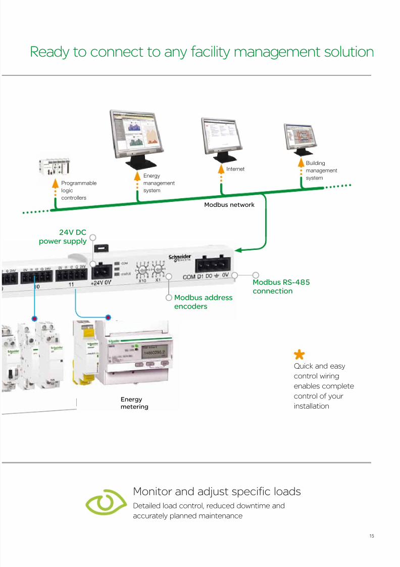
Ready to connect to any facility management solution
Monitor and adjust specific loads Detailed load control, reduced downtime and
accurately planned maintenance
Energymetering
Modbus network
Modbus addressencoders
24V DCpower supply
Modbus RS-485connection
Quick and easy
control wiring
enables complete
control of your installation
Energy
management
system
Programmable
logic
controllers
Building
management
system
Internet
7/16/2019 Acti9 Launch Catalogue
http://slidepdf.com/reader/full/acti9-launch-catalogue 16/124
16
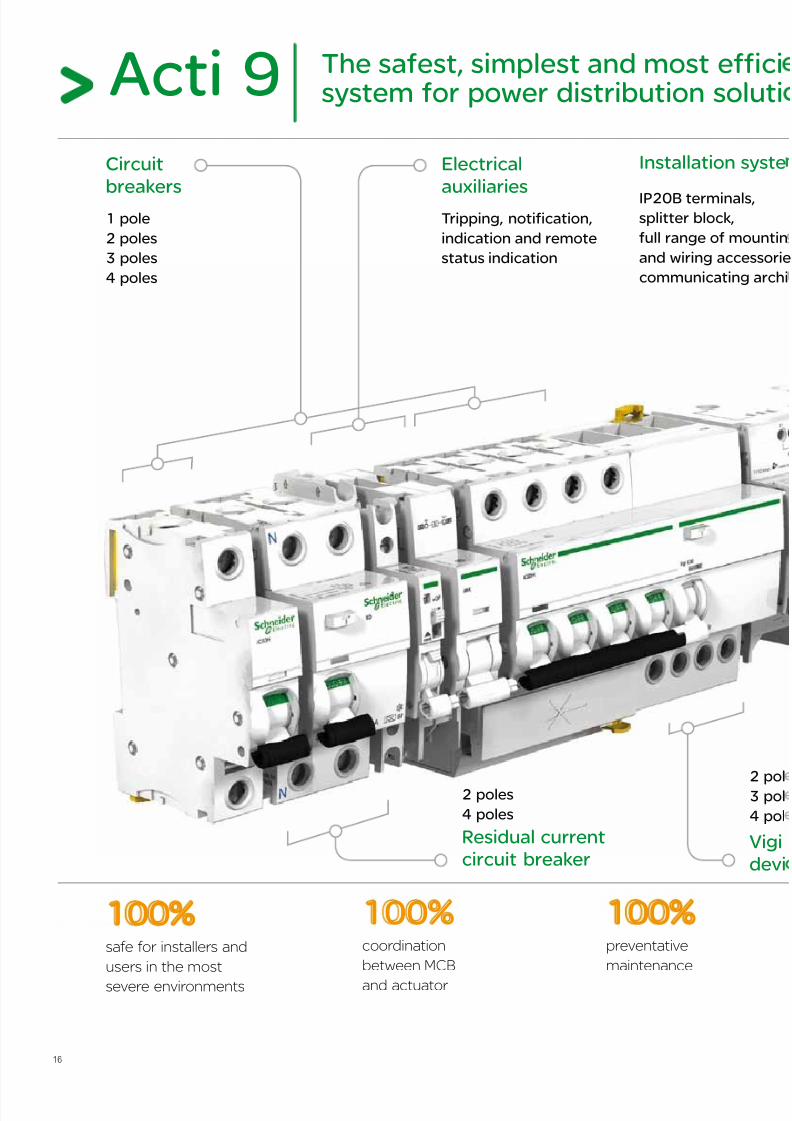
Electrical
auxiliariesTripping, notification,
indication and remote
status indication
1 pole
2 poles
3 poles
4 poles
Circuit
breakers
2 poles
4 poles
Residual current
circuit breaker
2 pol
3 pol
4 pol
Installation syste
IP20B terminals,splitter block,
full range of mountin
and wiring accessorie
communicating archi
Acti 9 The safest, simplest and most efficisystem for power distribution soluti
coordination
between MCB
and actuator
100%safe for installers and
users in the most
severe environments
100%preventative
maintenance
100%
Vigi
devi
7/16/2019 Acti9 Launch Catalogue
http://slidepdf.com/reader/full/acti9-launch-catalogue 17/124
17
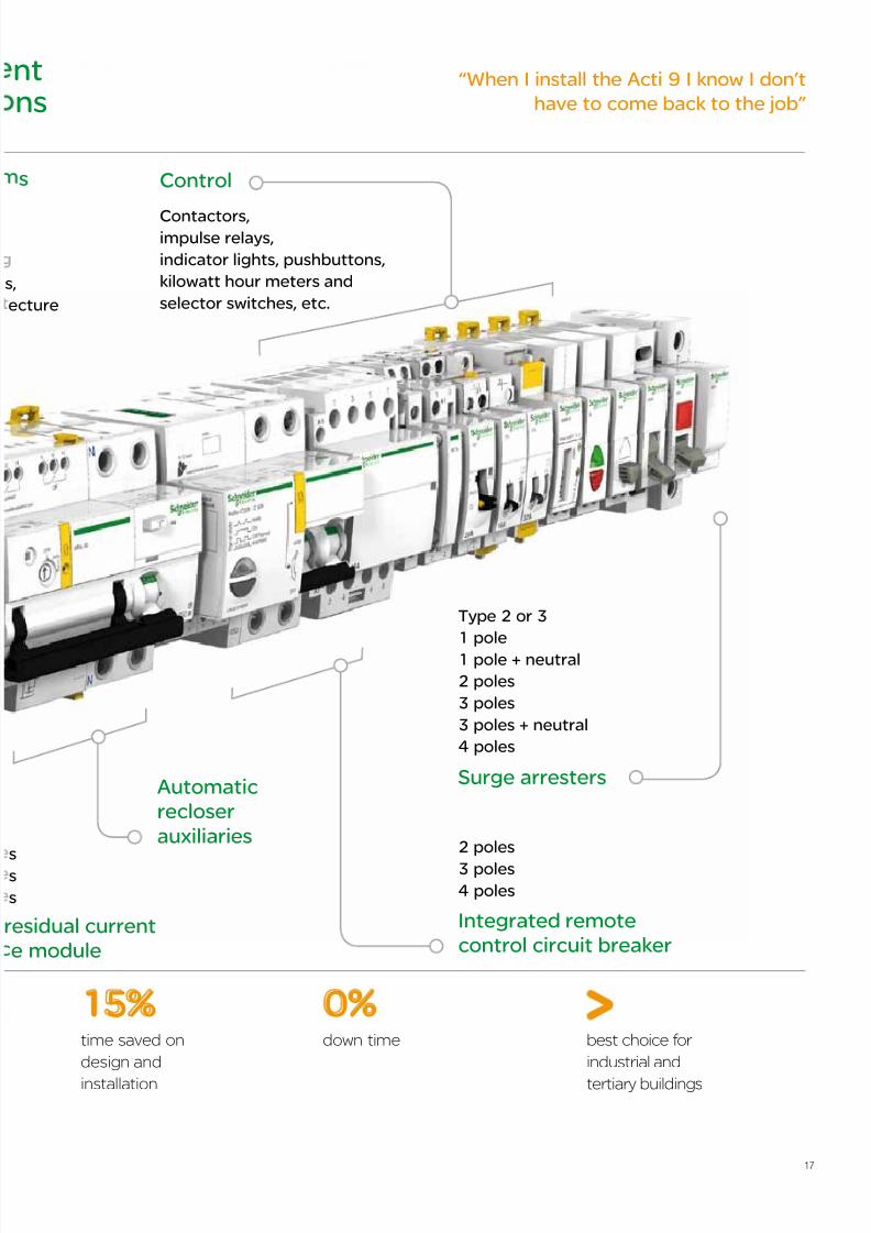
ture
tns
time saved on
design and
installation
15% 0%down time best choice for
industrial and
tertiary buildings
Control
Contactors,impulse relays,
indicator lights, pushbuttons,
kilowatt hour meters and
selector switches, etc.
2 poles
3 poles
4 poles
sidual current
module
Automatic
recloser
auxiliaries
Integrated remote
control circuit breaker
Type 2 or 3
1 pole
1 pole + neutral
2 poles
3 poles
3 poles + neutral
4 poles
Surge arresters
“When I install the Acti 9 I know I don’t
have to come back to the job”
7/16/2019 Acti9 Launch Catalogue
http://slidepdf.com/reader/full/acti9-launch-catalogue 18/124
18
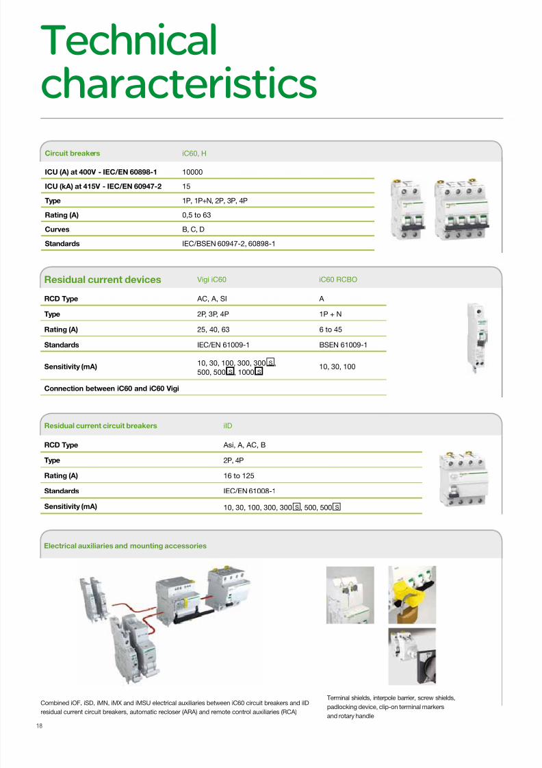
Circuit breakers iC60, H
ICU (A) at 400V - IEC/EN 60898-1 10000
ICU (kA) at 415V - IEC/EN 60947-2 15
Type 1P, 1P+N, 2P, 3P, 4P
Rating (A) 0,5 to 63
Curves B, C, D
Standards IEC/BSEN 60947-2, 60898-1
Residual current circuit breakers iID
RCD Type Asi, A, AC, B
Type 2P, 4P
Rating (A) 16 to 125
Standards IEC/EN 61008-1
Sensitivity (mA) 10, 30, 100, 300, 300 S , 500, 500 S
Residual current devices Vigi iC60 iC60 RCBO
RCD Type AC, A, SI A
Type 2P, 3P, 4P 1P + N
Rating (A) 25, 40, 63 6 to 45
Standards IEC/EN 61009-1 BSEN 61009-1
Sensitivity (mA)10, 30, 100, 300, 300 S ,
500, 500 S , 1000 S10, 30, 100
Connection between iC60 and iC60 Vigi
Technicalcharacteristics
Terminal shields, interpole barrier, screw shields,
padlocking device, clip-on terminal markers
and rotary handle
Electrical auxiliaries and mounting accessories
Combined iOF, iSD, iMN, iMX and iMSU electrical auxiliaries between iC60 circuit breakers and iID
residual current circuit breakers, automatic recloser (ARA) and remote control auxiliaries (RCA)
7/16/2019 Acti9 Launch Catalogue
http://slidepdf.com/reader/full/acti9-launch-catalogue 19/124
19
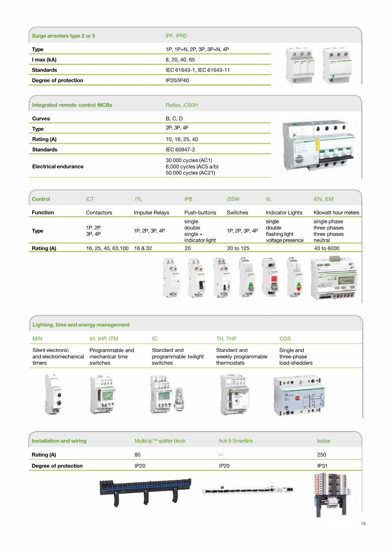
Integrated remote control MCBs Refex, iC60H
Curves B, C, D
Type 2P, 3P, 4P
Rating (A) 10, 16, 25, 40
Standards IEC 60947-2
Electrical endurance
30 000 cycles (AC1)
6,000 cycles (AC5 a/b)50 000 cycles (AC21)
Installation and wiring Multiclip™ splitter block Acti 9 Smartlink Isobar
Rating (A) 80 -- 250
Degree of protection IP20 IP20 IP31
Surge arresters type 2 or 3 iPF, iPRD
Type 1P, 1P+N, 2P, 3P, 3P+N, 4P
I max (kA) 8, 20, 40, 65
Standards IEC 61643-1, IEC 61643-11
Degree of protection IP20/IP40
Control iCT iTL iPB iSSW iIL iEN, iEM
Function Contactors Impulse Relays Push-buttons Switches Indicator Lights Kilowatt hour meters
Type1P, 2P
3P, 4P1P, 2P, 3P, 4P
single
double
single +indicator light
1P, 2P, 3P, 4P
single
double
fashing lightvoltage presence
single phase
three phases
three phasesneutral
Rating (A) 16, 25, 40, 63,100 16 & 32 20 20 to 125 40 to 6000
Lighting, time and energy management
MIN IH, IHP, ITM IC TH, THP CDS
Silent electronic
and electromechanical
timers
Programmable and
mechanical time
switches
Standard and
programmable twilight
switches
Standard and
weekly programmable
thermostats
Single and
three-phase
load-shedders

7/16/2019 Acti9 Launch Catalogue
http://slidepdf.com/reader/full/acti9-launch-catalogue 20/12420
7/16/2019 Acti9 Launch Catalogue
http://slidepdf.com/reader/full/acti9-launch-catalogue 21/124
Ordering
references
Acti9 Distribution boards 22
Introduction 22
A type 24
B type 28
Acti9 miniature circuit breakers 36
iC60H 1,2,3,4 pole Mcbs 36
iC60H single pole wide RCBO 40
iC60 Vigibloc 42
iC60 Auxiliaries 45
iC60 Accessories 52
Residual Current Circuit Breakers 56
iID RCCB 56
Technical 61
Dimensions 114
21
7/16/2019 Acti9 Launch Catalogue
http://slidepdf.com/reader/full/acti9-launch-catalogue 22/124
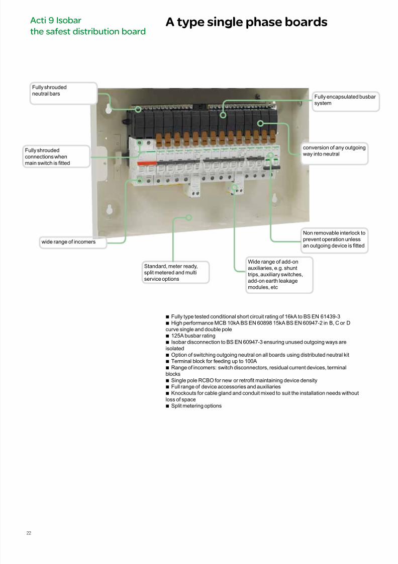
A type single phase boardsActi 9 Isobar
the safest distribution board
b Fully type tested conditional short circuit rating of 16kA to BS EN 61439-3 b High performance MCB 10kA BS EN 60898 15kA BS EN 60947-2 in B, C or D
curve single and double pole b 125A busbar rating b Isobar disconnection to BS EN 60947-3 ensuring unused outgoing ways are
isolated b Option of switching outgoing neutral on all boards using distributed neutral kit b Terminal block for feeding up to 100A b Range of incomers: switch disconnectors, residual current devices, terminal
blocks b Single pole RCBO for new or retrot maintaining device density b Full range of device accessories and auxiliaries
b Knockouts for cable gland and conduit mixed to suit the installation needs withoutloss of space b Split metering options
Standard, meter ready,split metered and multiservice options
Fully encapsulated busbar system
conversion of any outgoingway into neutral
Fully shroudedconnections whenmain switch is tted
Fully shroudedneutral bars
Wide range of add-onauxiliaries, e.g. shunttrips, auxiliary switches,add-on earth leakagemodules, etc
Non removable interlock toprevent operation unlessan outgoing device is tted
wide range of incomers
22
7/16/2019 Acti9 Launch Catalogue
http://slidepdf.com/reader/full/acti9-launch-catalogue 23/124
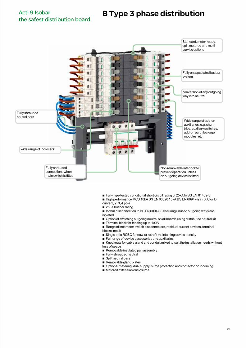
B Type 3 phase distributionActi 9 Isobar
the safest distribution board
b Fully type tested conditional short circuit rating of 25kA to BS EN 61439-3 b High performance MCB 10kA BS EN 60898 15kA BS EN 60947-2 in B, C or D
curve 1, 2, 3, 4 pole b 250A busbar rating b Isobar disconnection to BS EN 60947-3 ensuring unused outgoing ways are
isolated b Option of switching outgoing neutral on all boards using distributed neutral kit b Terminal block for feeding up to 100A b Range of incomers: switch disconnectors, residual current devices, terminal
blocks, mccb b Single pole RCBO for new or retrot maintaining device density b Full range of device accessories and auxiliaries
b Knockouts for cable gland and conduit mixed to suit the installation needs withoutloss of space b Removable insulated pan assembly b Fully shrouded neutral b Split neutral bars b Removable gland plates b Optional metering, dual supply, surge protection and contactor on incoming b Metered extension enclosures
Standard, meter ready,split metered and multiservice options
Fully encapsulated busbar system
conversion of any outgoingway into neutral
Fully shroudedconnections whenmain switch is tted
Fully shroudedneutral bars
Wide range of add-onauxiliaries, e.g. shunttrips, auxiliary switches,add-on earth leakagemodules, etc
Non removable interlock toprevent operation unlessan outgoing device is tted
wide range of incomers
23
7/16/2019 Acti9 Launch Catalogue
http://slidepdf.com/reader/full/acti9-launch-catalogue 24/124
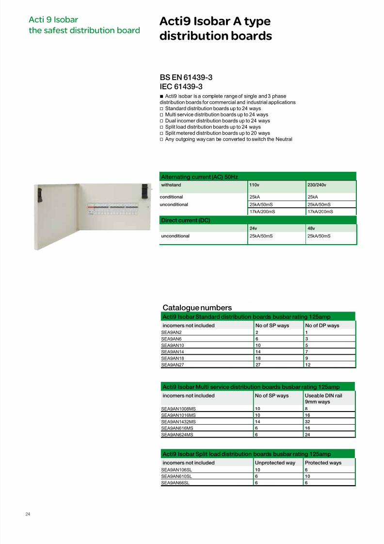
b Acti9 Isobar is a complete range of single and 3 phasedistribution boards for commercial and industrial applications
v Standard distribution boards up to 24 ways v Multi service distribution boards up to 24 ways v Dual incomer distribution boards up to 24 ways v Split load distribution boards up to 24 ways v Split metered distribution boards up to 20 ways v Any outgoing way can be converted to switch the Neutral
Alternating current (AC) 50Hz
withstand 110v 230/240v
conditional 25kA 25kA
unconditional 25kA/50mS 25kA/50mS
17kA/200mS 17kA/200mS
Direct current (DC)
24v 48v
unconditional 25kA/50mS 25kA/50mS
BS EN 61439-3
IEC 61439-3
Acti9 Isobar A type
distribution boards
Acti 9 Isobar
the safest distribution board
Catalogue numbers Acti9 Isobar Standard distribution boards busbar rating 125amp
incomers not included No o SP ways No o DP ways
SEA9AN2 2 1
SEA9AN6 6 3
SEA9AN10 10 5
SEA9AN14 14 7
SEA9AN18 18 9
SEA9AN27 27 12
Acti9 Isobar Multi service distribution boards busbar rating 125amp
incomers not included No o SP ways Useable DIN rail
9mm ways
SEA9AN1008MS 10 8
SEA9AN1016MS 10 16
SEA9AN1432MS 14 32
SEA9AN616MS 6 16
SEA9AN624MS 6 24
Acti9 Isobar Split load distribution boards busbar rating 125amp
incomers not included Unprotected way Protected ways
SEA9AN106SL 10 6
SEA9AN610SL 6 10SEA9AN66SL 6 6
24
7/16/2019 Acti9 Launch Catalogue
http://slidepdf.com/reader/full/acti9-launch-catalogue 25/124
Acti9 Isobar A type
distribution boards
Acti 9 Isobar
the safest distribution board
Technical data Standard, Meter ready, Split metered Acti9 Isobar
Main characteristics 110v 230/240v
According to BE EN 61439-3
Withstand conditional 25kA 25kA
unconditional 25kA/50mS 25kA/50mS
17kA/200mS 17kA/200mS
insulation voltage (Ui)
Pollution degree
Rated inpulse withstand voltage (Uimp)
Current rating (A) direct connection 125
Switch disconnector 125 DIN mounted Power switchRCCB 100
sensetivites (mA) 30, 100, 300, 300TD
Degree of protection External IP30
(IEC 60529) Internal IP20
Endurance (O-C) Isobar switchdisconnector
3000
Overvoltage category IV
Operating temperature -35 to +700C
Storage teperature -40 to +800C
Connections
Rating tightening torque Copper lugs cables bare device
125 amp b 50mm DIN switch disconnector
125 ampb
50mm Terminal block100 amp b 35mm RCCB
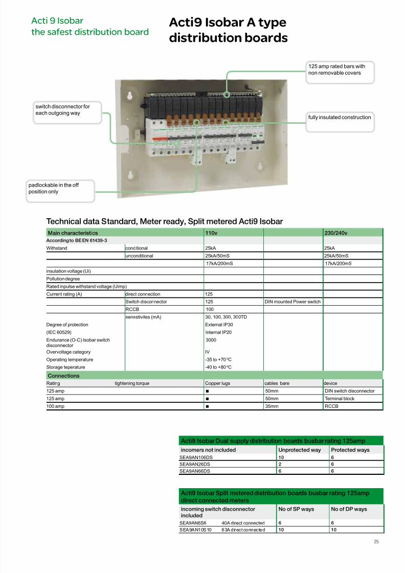
125 amp rated bars withnon removable covers
fully insulated construction
padlockable in the off position only
switch disconnector for each outgoing way
Acti9 Isobar Dual supply distribution boards busbar rating 125amp
incomers not included Unprotected way Protected ways
SEA9AN106DS 10 6
SEA9AN26DS 2 6
SEA9AN66DS 6 6
Acti9 Isobar Split metered distribution boards busbar rating 125amp
direct connected metersincoming switch disconnector
included
No o SP ways No o DP ways
SEA9AN6S6 40A direct connected 6 6
SEA9AN10S10 63A direct connected 10 10
25
7/16/2019 Acti9 Launch Catalogue
http://slidepdf.com/reader/full/acti9-launch-catalogue 26/124
Acti9 Isobar A type
distribution boards
Acti 9 Isobar
the safest distribution board
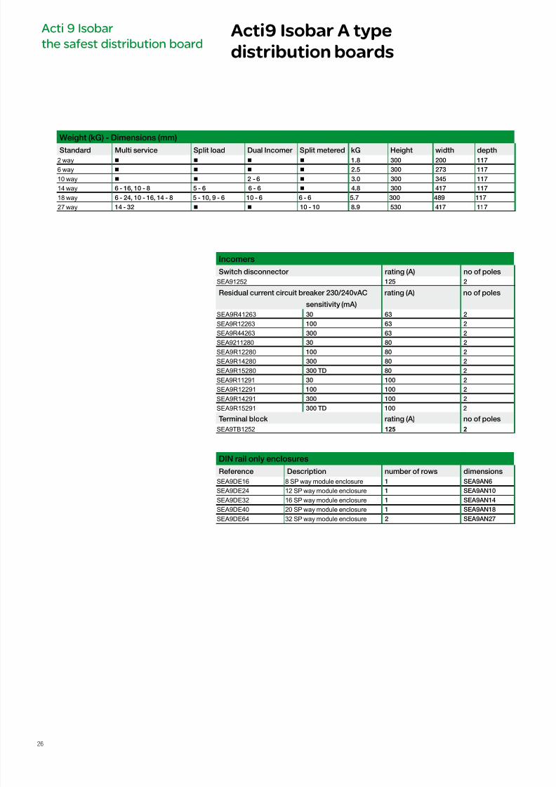
Weight (kG) - Dimensions (mm)Standard Multi service Split load Dual Incomer Split metered kG Height width depth
2 way b b b b 1.8 300 200 117
6 way b b b b 2.5 300 273 117
10 way b b 2 - 6 b 3.0 300 345 117
14 way 6 - 16, 10 - 8 5 - 6 6 - 6 b 4.8 300 417 117
18 way 6 - 24, 10 - 16, 14 - 8 5 - 10, 9 - 6 10 - 6 6 - 6 5.7 300 489 117
27 way 14 - 32 b b 10 - 10 8.9 530 417 117
Incomers
Switch disconnector rating (A) no o polesSEA91252 125 2
DIN rail only enclosures
Reerence Description number o rows dimensions
SEA9DE16 8 SP way module enclosure 1 SEA9AN6
SEA9DE24 12 SP way module enclosure 1 SEA9AN10
SEA9DE32 16 SP way module enclosure 1 SEA9AN14
SEA9DE40 20 SP way module enclosure 1 SEA9AN18
SEA9DE64 32 SP way module enclosure 2 SEA9AN27
Residual current circuit breaker 230/240vAC rating (A) no o poles
sensitivity (mA)
SEA9R41263 30 63 2
SEA9R12263 100 63 2
SEA9R44263 300 63 2
SEA9211280 30 80 2
SEA9R12280 100 80 2
SEA9R14280 300 80 2
SEA9R15280 300 TD 80 2
SEA9R11291 30 100 2
SEA9R12291 100 100 2
SEA9R14291 300 100 2
SEA9R15291 300 TD 100 2
Terminal block rating (A) no o poles
SEA9TB1252 125 2
26
7/16/2019 Acti9 Launch Catalogue
http://slidepdf.com/reader/full/acti9-launch-catalogue 27/124
Acti9 Isobar A type
distribution boards
Acti 9 Isobar
the safest distribution board
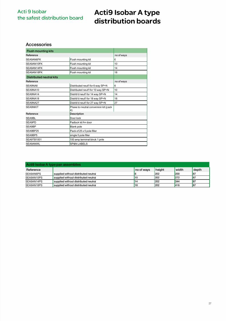
Accessories
Flush mounting kits
Reerence no of waysSEA9AN6FK Flush mounting kit 6
SEA9AN10FK Flush mounting kit 10
SEA9AN14FK Flush mounting kit 14
SEA9AN18FK Flush mounting kit 18
Distributed neutral kits
Reerence no of ways
SEA9NA6 Distributed neut'l for 6 way SP+N 6
SEA9NA10 Distributed neut'l for 10 way SP+N 10
SEA9NA14 Distrib'd neut'l for 14 way SP+N 14
SEA9NA18 Distrib'd neut'l for 18 way SP+N 18
SEA9NA27 Distrib'd neut'l for 27 way SP+N 27
SEA9NKIT Phase to neutral conversion kit (pack4)
Reerence Description
SEA9BL Door lock
SEA9PD Padlock kit for door
SEA9BP Blank pole
SEA9BP25 Pack of 25 x 5 pole ller
SEA9BP5 single 5 pole ller
SEA9TB1001 100 amp terminal block 1 pole
SEA9ANWL SP&N LABELS
Acti9 Isobar A type pan assemblies
Reerence no o ways height width depth
SEA9AN6PS supplied without distributed neutral 6 202 200 87
SEA9AN10PS supplied without distributed neutral 10 202 272 87
SEA9AN14PS supplied without distributed neutral 14 202 344 87
SEA9AN18PS supplied without distributed neutral 18 202 416 87
27
7/16/2019 Acti9 Launch Catalogue
http://slidepdf.com/reader/full/acti9-launch-catalogue 28/124
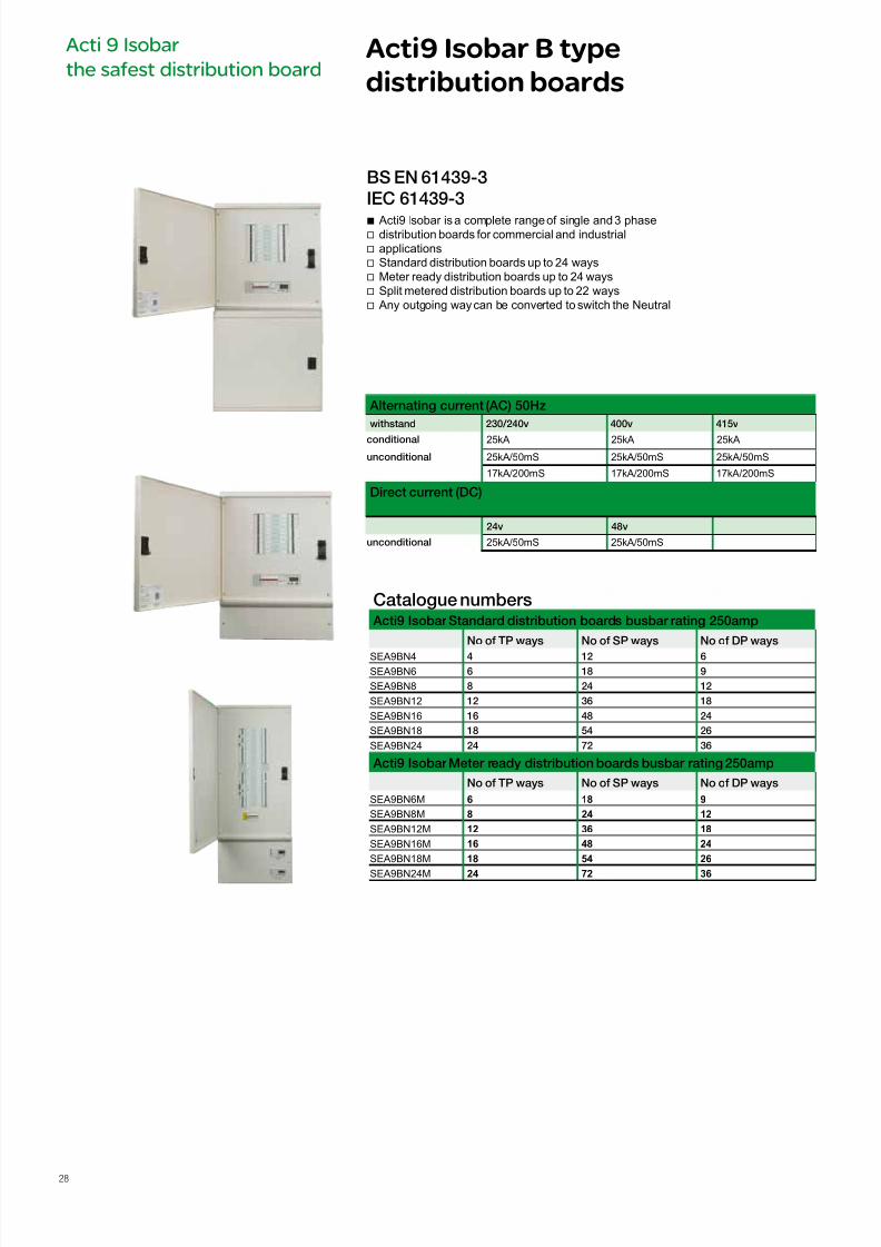
b Acti9 Isobar is a complete range of single and 3 phasev distribution boards for commercial and industrial
v applications v Standard distribution boards up to 24 ways v Meter ready distribution boards up to 24 ways v Split metered distribution boards up to 22 ways v Any outgoing way can be converted to switch the Neutral
Alternating current (AC) 50Hz
withstand 230/240v 400v 415v
conditional 25kA 25kA 25kA
unconditional 25kA/50mS 25kA/50mS 25kA/50mS
17kA/200mS 17kA/200mS 17kA/200mS
Direct current (DC)
24v 48v
unconditional 25kA/50mS 25kA/50mS
BS EN 61439-3
IEC 61439-3
Acti9 Isobar B type
distribution boards
Acti 9 Isobar
the safest distribution board
Catalogue numbers Acti9 Isobar Standard distribution boards busbar rating 250amp
No o TP ways No o SP ways No o DP ways
SEA9BN4 4 12 6
SEA9BN6 6 18 9
SEA9BN8 8 24 12
SEA9BN12 12 36 18
SEA9BN16 16 48 24
SEA9BN18 18 54 26
SEA9BN24 24 72 36
Acti9 Isobar Meter ready distribution boards busbar rating 250amp
No o TP ways No o SP ways No o DP ways
SEA9BN6M 6 18 9
SEA9BN8M 8 24 12
SEA9BN12M 12 36 18
SEA9BN16M 16 48 24
SEA9BN18M 18 54 26
SEA9BN24M 24 72 36
28
7/16/2019 Acti9 Launch Catalogue
http://slidepdf.com/reader/full/acti9-launch-catalogue 29/124
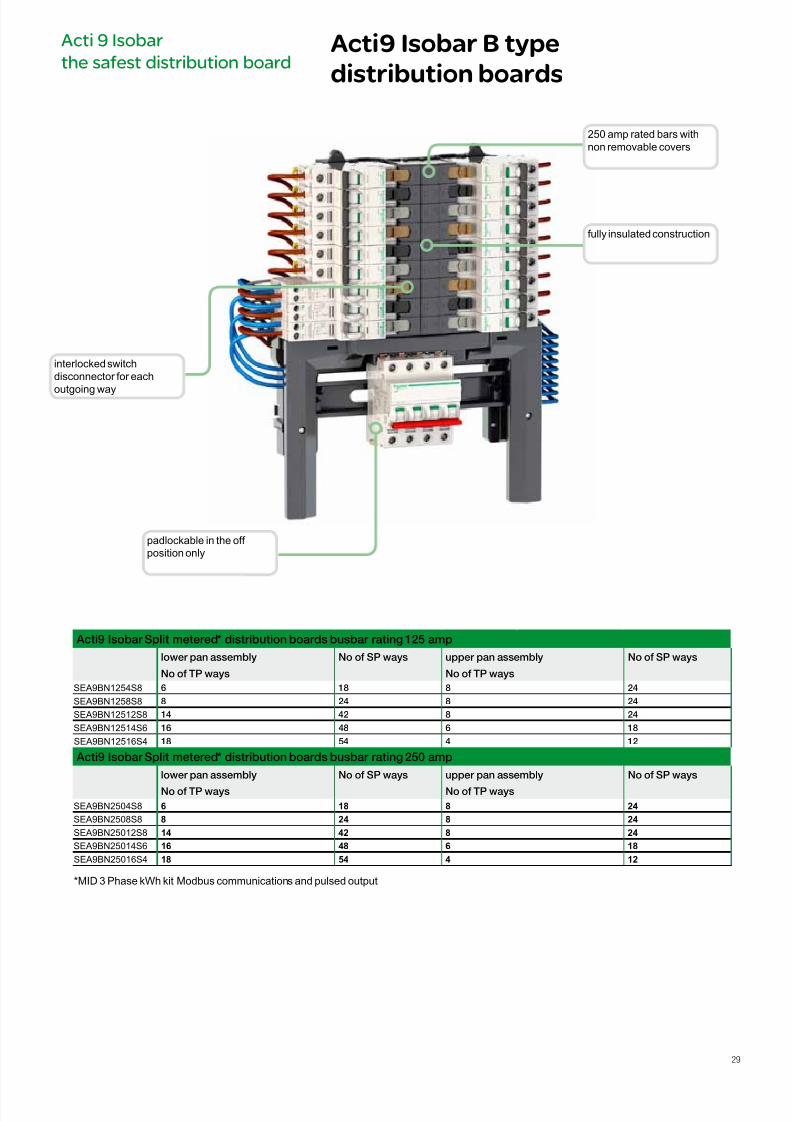
Acti9 Isobar Split metered* distribution boards busbar rating 125 amp
lower pan assembly
No o TP ways
No o SP ways upper pan assembly
No o TP ways
No o SP ways
SEA9BN1254S8 6 18 8 24
SEA9BN1258S8 8 24 8 24
SEA9BN12512S8 14 42 8 24
SEA9BN12514S6 16 48 6 18
SEA9BN12516S4 18 54 4 12
Acti9 Isobar Split metered* distribution boards busbar rating 250 amp
lower pan assembly
No o TP ways
No o SP ways upper pan assembly
No o TP ways
No o SP ways
SEA9BN2504S8 6 18 8 24
SEA9BN2508S8 8 24 8 24
SEA9BN25012S8 14 42 8 24
SEA9BN25014S6 16 48 6 18
SEA9BN25016S4 18 54 4 12
250 amp rated bars withnon removable covers
fully insulated construction
padlockable in the off position only
interlocked switchdisconnector for each
outgoing way
*MID 3 Phase kWh kit Modbus communications and pulsed output
Acti 9 Isobar
the safest distribution boardActi9 Isobar B type
distribution boards
29
7/16/2019 Acti9 Launch Catalogue
http://slidepdf.com/reader/full/acti9-launch-catalogue 30/124
Acti9 Isobar B type
distribution boards
Acti 9 Isobar
the safest distribution board
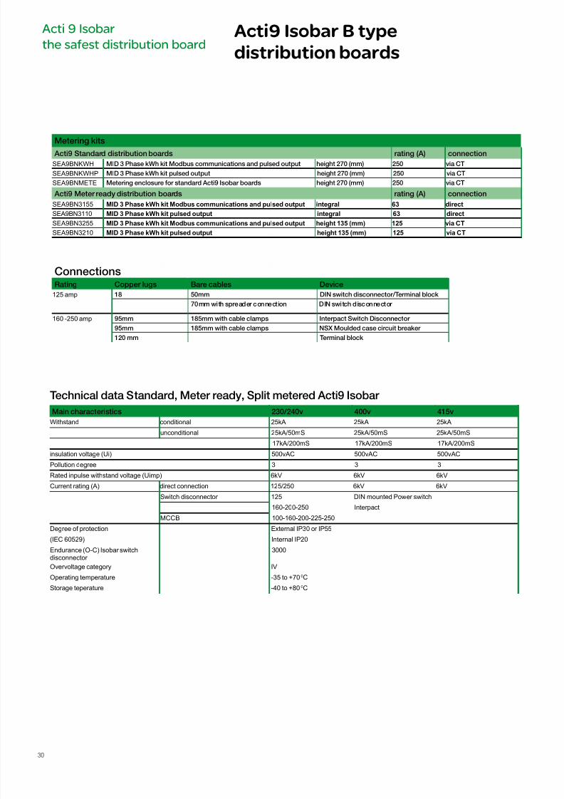
Metering kits
Acti9 Standard distribution boards rating (A) connection
SEA9BNKWH MID 3 Phase kWh kit Modbus communications and pulsed output height 270 (mm) 250 via CT
SEA9BNKWHP MID 3 Phase kWh kit pulsed output height 270 (mm) 250 via CT
SEA9BNMETE Metering enclosure or standard Acti9 Isobar boards height 270 (mm) 250 via CT
Acti9 Meter ready distribution boards rating (A) connection
SEA9BN3155 MID 3 Phase kWh kit Modbus communications and pulsed output integral 63 direct
SEA9BN3110 MID 3 Phase kWh kit pulsed output integral 63 direct
SEA9BN3255 MID 3 Phase kWh kit Modbus communications and pulsed output height 135 (mm) 125 via CT
SEA9BN3210 MID 3 Phase kWh kit pulsed output height 135 (mm) 125 via CT
Technical data Standard, Meter ready, Split metered Acti9 Isobar
Main characteristics 230/240v 400v 415v
Withstand conditional 25kA 25kA 25kA
unconditional 25kA/50mS 25kA/50mS 25kA/50mS
17kA/200mS 17kA/200mS 17kA/200mS
insulation voltage (Ui) 500vAC 500vAC 500vAC
Pollution degree 3 3 3
Rated inpulse withstand voltage (Uimp) 6kV 6kV 6kV
Current rating (A) direct connection 125/250 6kV 6kV
Switch disconnector 125 DIN mounted Power switch
160-200-250 Interpact
MCCB 100-160-200-225-250
Degree of protection External IP30 or IP55
(IEC 60529) Internal IP20
Endurance (O-C) Isobar switch
disconnector
3000
Overvoltage category IV
Operating temperature -35 to +700C
Storage teperature -40 to +800C
ConnectionsRating Copper lugs Bare cables Device
125 amp 18 50mm DIN switch disconnector/Terminal block
70mm with spreader connection DIN switch disconnector
160 -250 amp 95mm 185mm with cable clamps Interpact Switch Disconnector
95mm 185mm with cable clamps NSX Moulded case circuit breaker
120 mm Terminal block
30
7/16/2019 Acti9 Launch Catalogue
http://slidepdf.com/reader/full/acti9-launch-catalogue 31/124
Acti 9 Isobar
the safest distribution boardActi9 Isobar B type
distribution boards
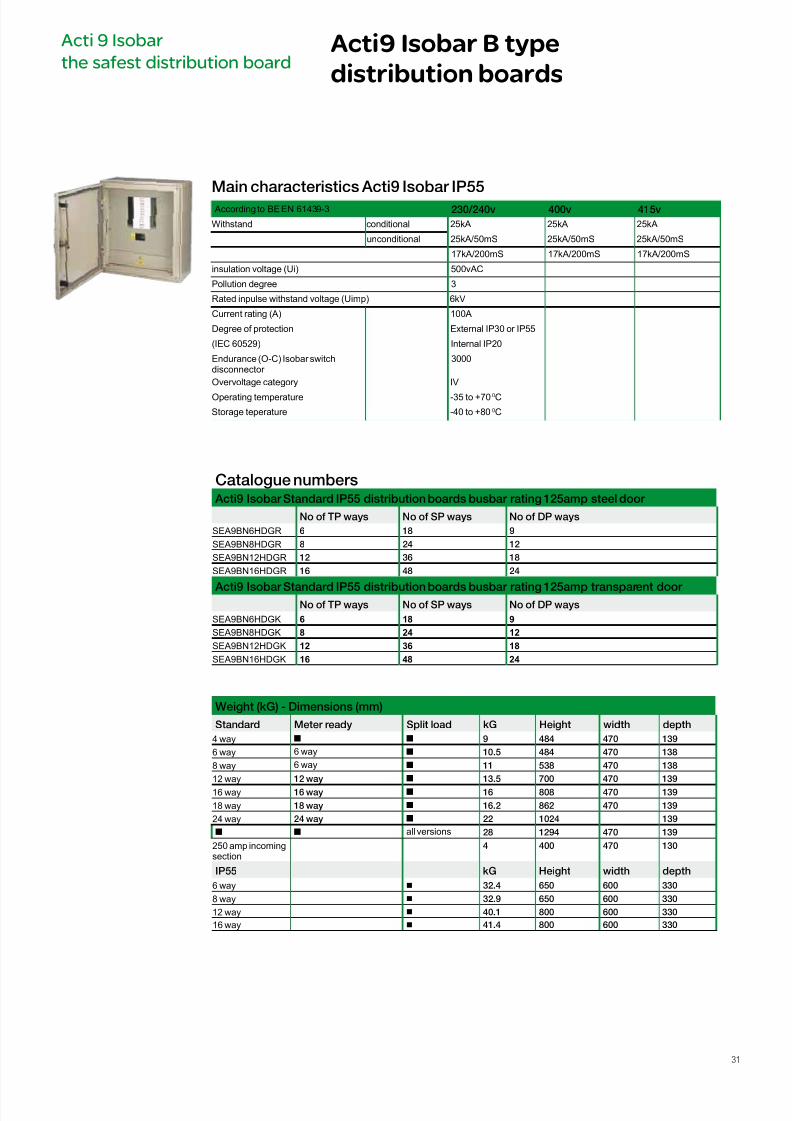
Main characteristics Acti9 Isobar IP55
According to BE EN 61439-3 230/240v 400v 415v
Withstand conditional 25kA 25kA 25kA
unconditional 25kA/50mS 25kA/50mS 25kA/50mS
17kA/200mS 17kA/200mS 17kA/200mS
insulation voltage (Ui) 500vAC
Pollution degree 3
Rated inpulse withstand voltage (Uimp) 6kV
Current rating (A) 100A
Degree of protection External IP30 or IP55
(IEC 60529) Internal IP20
Endurance (O-C) Isobar switchdisconnector
3000
Overvoltage category IV
Operating temperature -35 to +700C
Storage teperature -40 to +800C
Catalogue numbers Acti9 Isobar Standard IP55 distribution boards busbar rating 125amp steel door
No o TP ways No o SP ways No o DP ways
SEA9BN6HDGR 6 18 9
SEA9BN8HDGR 8 24 12
SEA9BN12HDGR 12 36 18
SEA9BN16HDGR 16 48 24
Acti9 Isobar Standard IP55 distribution boards busbar rating 125amp transparent door No o TP ways No o SP ways No o DP ways
SEA9BN6HDGK 6 18 9
SEA9BN8HDGK 8 24 12
SEA9BN12HDGK 12 36 18
SEA9BN16HDGK 16 48 24
Weight (kG) - Dimensions (mm)
Standard Meter ready Split load kG Height width depth
4 way n n 9 484 470 139
6 way 6 way n 10.5 484 470 138
8 way 6 way n 11 538 470 138
12 way 12 way n 13.5 700 470 139
16 way 16 way n 16 808 470 139
18 way 18 way n 16.2 862 470 139
24 way 24 way n 22 1024 139
n n all versions 28 1294 470 139
250 amp incomingsection
4 400 470 130
IP55 kG Height width depth
6 way b 32.4 650 600 330
8 way b 32.9 650 600 330
12 way b 40.1 800 600 330
16 way b 41.4 800 600 330
31
7/16/2019 Acti9 Launch Catalogue
http://slidepdf.com/reader/full/acti9-launch-catalogue 32/124
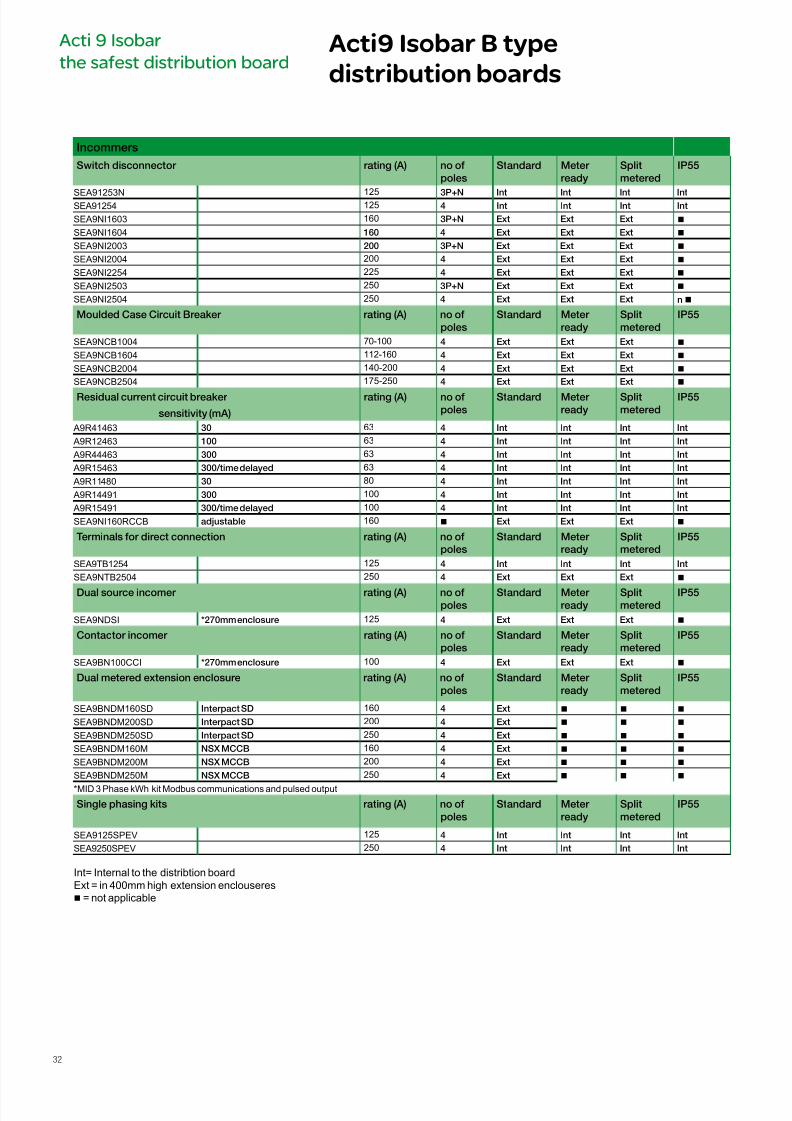
Incommers
Switch disconnector rating (A) no o
poles
Standard Meter
ready
Split
metered
IP55
SEA91253N 125 3P+N Int Int Int IntSEA91254 125 4 Int Int Int Int
SEA9NI1603 160 3P+N Ext Ext Ext n
SEA9NI1604 160 4 Ext Ext Ext n
SEA9NI2003 200 3P+N Ext Ext Ext n
SEA9NI2004 200 4 Ext Ext Ext n
SEA9NI2254 225 4 Ext Ext Ext n
SEA9NI2503 250 3P+N Ext Ext Ext n
SEA9NI2504 250 4 Ext Ext Ext n n
Moulded Case Circuit Breaker rating (A) no o
poles
Standard Meter
ready
Split
metered
IP55
SEA9NCB1004 70-100 4 Ext Ext Ext n
SEA9NCB1604 112-160 4 Ext Ext Ext n
SEA9NCB2004 140-200 4 Ext Ext Ext n
SEA9NCB2504 175-250 4 Ext Ext Ext n
Residual current circuit breaker
sensitivity (mA)
rating (A) no o
poles
Standard Meter
ready
Split
metered
IP55
A9R41463 30 63 4 Int Int Int Int
A9R12463 100 63 4 Int Int Int Int
A9R44463 300 63 4 Int Int Int Int
A9R15463 300/time delayed 63 4 Int Int Int Int
A9R11480 30 80 4 Int Int Int Int
A9R14491 300 100 4 Int Int Int Int
A9R15491 300/time delayed 100 4 Int Int Int Int
SEA9NI160RCCB adjustable 160 n Ext Ext Ext n
Terminals or direct connection rating (A) no o
poles
Standard Meter
ready
Split
metered
IP55
SEA9TB1254 125 4 Int Int Int Int
SEA9NTB2504 250 4 Ext Ext Ext n
Dual source incomer rating (A) no o
poles
Standard Meter
ready
Split
metered
IP55
SEA9NDSI *270mm enclosure 125 4 Ext Ext Ext n
Contactor incomer rating (A) no o
poles
Standard Meter
ready
Split
metered
IP55
SEA9BN100CCI *270mm enclosure 100 4 Ext Ext Ext n
Dual metered extension enclosure rating (A) no o
poles
Standard Meter
ready
Split
metered
IP55
SEA9BNDM160SD Interpact SD 160 4 Ext n n n
SEA9BNDM200SD Interpact SD 200 4 Ext n n n
SEA9BNDM250SD Interpact SD 250 4 Ext n n n
SEA9BNDM160M NSX MCCB 160 4 Ext n n n
SEA9BNDM200M NSX MCCB 200 4 Ext n n n
SEA9BNDM250M NSX MCCB 250 4 Ext n n n
*MID 3 Phase kWh kit Modbus communications and pulsed output
Single phasing kits rating (A) no o
poles
Standard Meter
ready
Split
metered
IP55
SEA9125SPEV 125 4 Int Int Int Int
SEA9250SPEV 250 4 Int Int Int Int
Acti9 Isobar B type
distribution boards
Acti 9 Isobar
the safest distribution board
Int= Internal to the distribtion boardExt = in 400mm high extension enclouseresn = not applicable
32
7/16/2019 Acti9 Launch Catalogue
http://slidepdf.com/reader/full/acti9-launch-catalogue 33/124
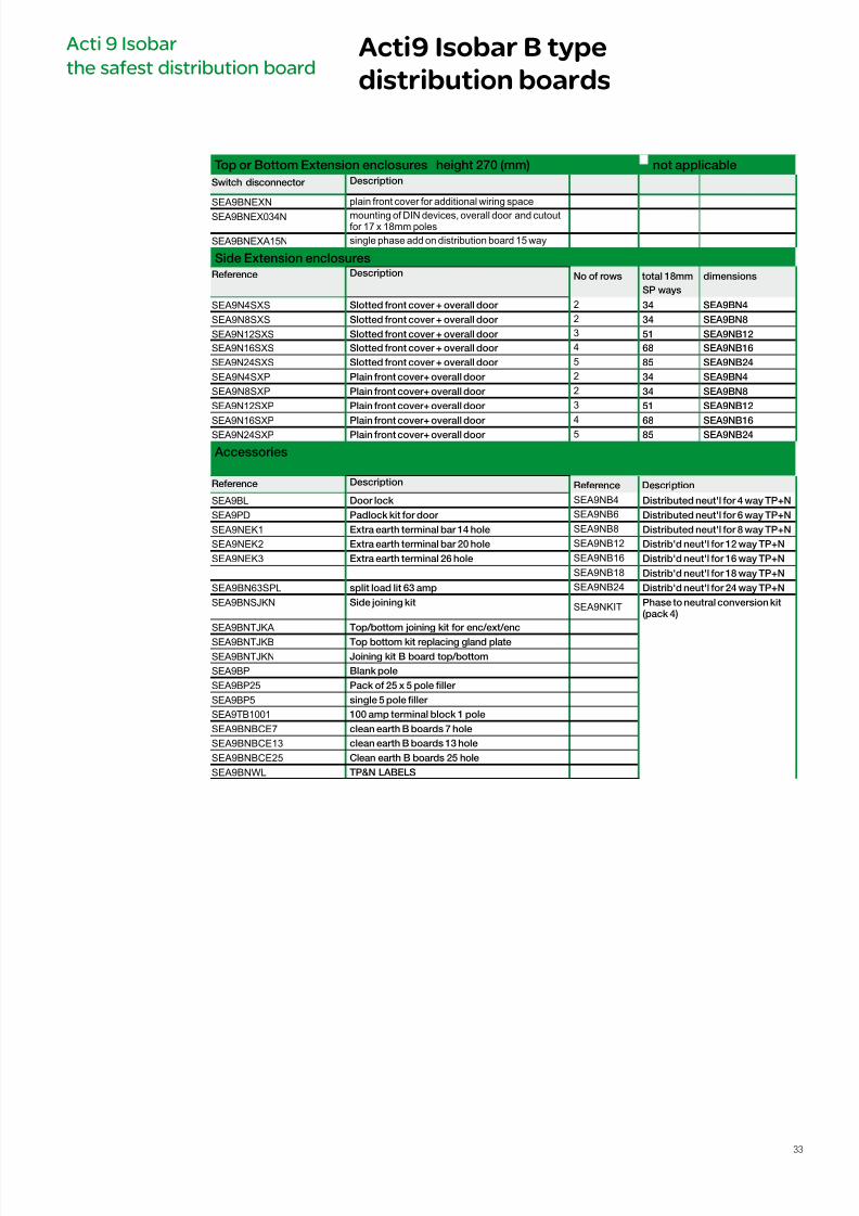
Top or Bottom Extension enclosures height 270 (mm) not applicable
Switch disconnector Description
SEA9BNEXN plain front cover for additional wiring space
SEA9BNEX034N mounting of DIN devices, overall door and cutoutfor 17 x 18mm poles
SEA9BNEXA15N single phase add on distribution board 15 way
Side Extension enclosures
Reerence Description No o rows total 18mm
SP ways
dimensions
SEA9N4SXS Slotted ront cover + overall door 2 34 SEA9BN4
SEA9N8SXS Slotted ront cover + overall door 2 34 SEA9BN8
SEA9N12SXS Slotted ront cover + overall door 3 51 SEA9NB12
SEA9N16SXS Slotted ront cover + overall door 4 68 SEA9NB16
SEA9N24SXS Slotted ront cover + overall door 5 85 SEA9NB24
SEA9N4SXP Plain ront cover+ overall door 2 34 SEA9BN4
SEA9N8SXP Plain ront cover+ overall door 2 34 SEA9BN8
SEA9N12SXP Plain ront cover+ overall door 3 51 SEA9NB12
SEA9N16SXP Plain ront cover+ overall door 4
68 SEA9NB16SEA9N24SXP Plain ront cover+ overall door 5 85 SEA9NB24
Accessories
Reerence Description Reerence Description
SEA9BL Door lock SEA9NB4 Distributed neut'l or 4 way TP+N
SEA9PD Padlock kit or door SEA9NB6 Distributed neut'l or 6 way TP+N
SEA9NEK1 Extra earth terminal bar 14 hole SEA9NB8 Distributed neut'l or 8 way TP+N
SEA9NEK2 Extra earth terminal bar 20 hole SEA9NB12 Distrib'd neut'l or 12 way TP+N
SEA9NEK3 Extra earth terminal 26 hole SEA9NB16 Distrib'd neut'l or 16 way TP+N
SEA9NB18 Distrib'd neut'l or 18 way TP+N
SEA9BN63SPL split load lit 63 amp SEA9NB24 Distrib'd neut'l or 24 way TP+N
SEA9BNSJKN Side joining kit SEA9NKIT Phase to neutral conversion kit(pack 4)
SEA9BNTJKA Top/bottom joining kit or enc/ext/enc
SEA9BNTJKB Top bottom kit replacing gland plate
SEA9BNTJKN Joining kit B board top/bottom
SEA9BP Blank pole
SEA9BP25 Pack o 25 x 5 pole ller
SEA9BP5 single 5 pole ller
SEA9TB1001 100 amp terminal block 1 pole
SEA9BNBCE7 clean earth B boards 7 hole
SEA9BNBCE13 clean earth B boards 13 hole
SEA9BNBCE25 Clean earth B boards 25 hole
SEA9BNWL TP&N LABELS
Acti 9 Isobar
the safest distribution boardActi9 Isobar B type
distribution boards
33
7/16/2019 Acti9 Launch Catalogue
http://slidepdf.com/reader/full/acti9-launch-catalogue 34/124
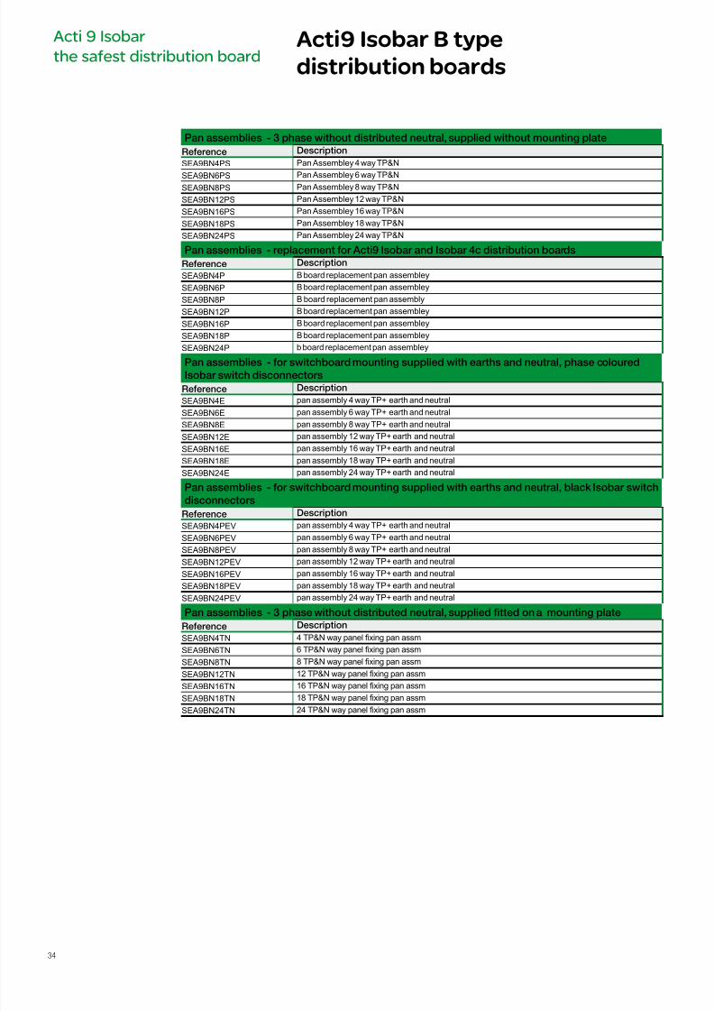
Pan assemblies - replacement or Acti9 Isobar and Isobar 4c distribution boards
Reerence Description
SEA9BN4P B board replacement pan assembley
SEA9BN6P B board replacement pan assembley
SEA9BN8P B board replacement pan assembly
SEA9BN12P B board replacement pan assembley
SEA9BN16P B board replacement pan assembley
SEA9BN18P B board replacement pan assembley
SEA9BN24P b board replacement pan assembley
Pan assemblies - or switchboard mounting supplied with earths and neutral, phase coloured
Isobar switch disconnectors
Reerence Description
SEA9BN4E pan assembly 4 way TP+ earth and neutral
SEA9BN6E pan assembly 6 way TP+ earth and neutral
SEA9BN8E pan assembly 8 way TP+ earth and neutral
SEA9BN12E pan assembly 12 way TP+ earth and neutral
SEA9BN16E pan assembly 16 way TP+ earth and neutral
SEA9BN18E pan assembly 18 way TP+ earth and neutral
SEA9BN24E pan assembly 24 way TP+ earth and neutral
Pan assemblies - or switchboard mounting supplied with earths and neutral, black Isobar switch
disconnectors
Reerence Description
SEA9BN4PEV pan assembly 4 way TP+ earth and neutral
SEA9BN6PEV pan assembly 6 way TP+ earth and neutral
SEA9BN8PEV pan assembly 8 way TP+ earth and neutral
SEA9BN12PEV pan assembly 12 way TP+ earth and neutral
SEA9BN16PEV pan assembly 16 way TP+ earth and neutral
SEA9BN18PEV pan assembly 18 way TP+ earth and neutral
SEA9BN24PEV pan assembly 24 way TP+ earth and neutral
Pan assemblies - 3 phase without distributed neutral, supplied tted on a mounting plate
Reerence Description
SEA9BN4TN 4 TP&N way panel xing pan assm
SEA9BN6TN 6 TP&N way panel xing pan assm
SEA9BN8TN 8 TP&N way panel xing pan assm
SEA9BN12TN 12 TP&N way panel xing pan assm
SEA9BN16TN 16 TP&N way panel xing pan assm
SEA9BN18TN 18 TP&N way panel xing pan assm
SEA9BN24TN 24 TP&N way panel xing pan assm
Pan assemblies - 3 phase without distributed neutral, supplied without mounting plate
Reerence Description
SEA9BN4PS Pan Assembley 4 way TP&N
SEA9BN6PS Pan Assembley 6 way TP&NSEA9BN8PS Pan Assembley 8 way TP&N
SEA9BN12PS Pan Assembley 12 way TP&N
SEA9BN16PS Pan Assembley 16 way TP&N
SEA9BN18PS Pan Assembley 18 way TP&N
SEA9BN24PS Pan Assembley 24 way TP&N
Acti9 Isobar B type
distribution boards
Acti 9 Isobar
the safest distribution board
34
7/16/2019 Acti9 Launch Catalogue
http://slidepdf.com/reader/full/acti9-launch-catalogue 35/124
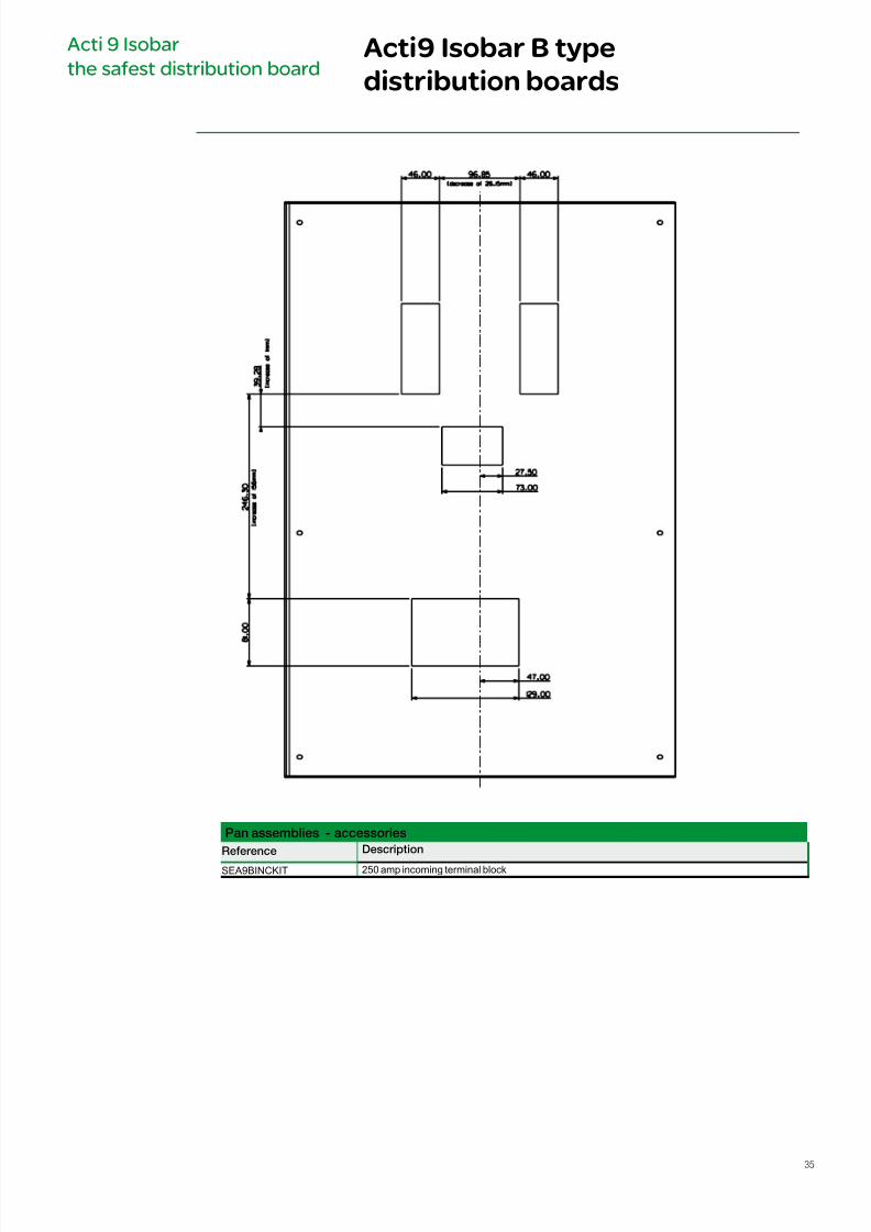
Pan assemblies - accessories
Reerence Description
SEA9BINCKIT 250 amp incoming terminal block
Acti 9 Isobar
the safest distribution boardActi9 Isobar B type
distribution boards
35
7/16/2019 Acti9 Launch Catalogue
http://slidepdf.com/reader/full/acti9-launch-catalogue 36/12436
iC60H circuit breakers
(curve B, C, D)
Protection
Circuit protection
(1) VDE approved only.
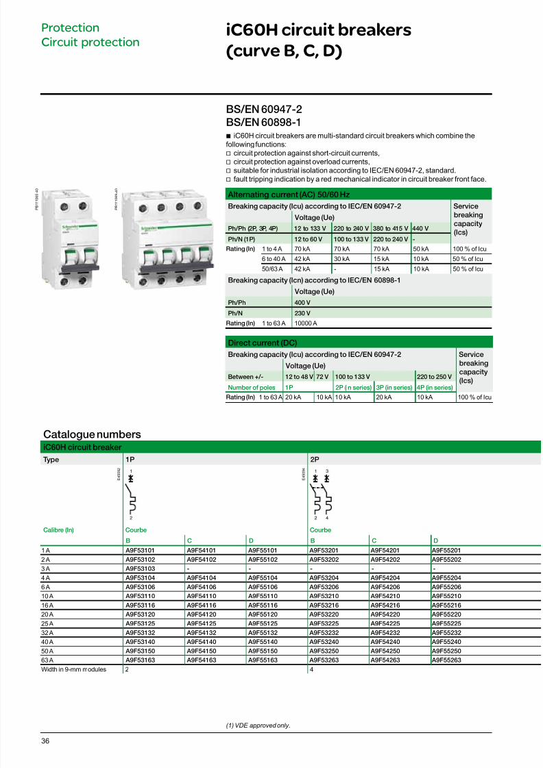
b iC60H circuit breakers are multi-standard circuit breakers which combine thefollowing functions:v circuit protection against short-circuit currents,
v circuit protection against overload currents, v suitable for industrial isolation according to IEC/EN 60947-2, standard. v fault tripping indication by a red mechanical indicator in circuit breaker front face.
Alternating current (AC) 50/60 Hz
Breaking capacity (Icu) according to IEC/EN 60947-2 Service
breaking
capacity
(Ics)
Voltage (Ue)
Ph/Ph (2P, 3P, 4P) 12 to 133 V 220 to 240 V 380 to 415 V 440 V
Ph/N (1P) 12 to 60 V 100 to 133 V 220 to 240 V -
Rating (In) 1 to 4 A 70 kA 70 kA 70 kA 50 kA 100 % of Icu
6 to 40 A 42 kA 30 kA 15 kA 10 kA 50 % of Icu
50/63 A 42 kA - 15 kA 10 kA 50 % of IcuBreaking capacity (Icn) according to IEC/EN 60898-1
Voltage (Ue)
Ph/Ph 400 V
Ph/N 230 V
Rating (In) 1 to 63 A 10000 A
Direct current (DC)
Breaking capacity (Icu) according to IEC/EN 60947-2 Service
breaking
capacity
(Ics)
Voltage (Ue)
Between +/- 12 to 48 V 72 V 100 to 133 V 220 to 250 V
Number o poles 1P 2P (in series) 3P (in series) 4P (in series)
Rating (In) 1 to 63 A 20 kA 10 kA 10 kA 20 kA 10 kA 100 % of Icu
BS/EN 60947-2
BS/EN 60898-1
Catalogue numbersiC60H circuit breaker
Type 1P 2P
1
2
1
2
3
4
Calibre (In) Courbe Courbe
B C D B C D
1 A A9F53101 A9F54101 A9F55101 A9F53201 A9F54201 A9F55201
2 A A9F53102 A9F54102 A9F55102 A9F53202 A9F54202 A9F55202
3 A A9F53103 - - - - -
4 A A9F53104 A9F54104 A9F55104 A9F53204 A9F54204 A9F55204
6 A A9F53106 A9F54106 A9F55106 A9F53206 A9F54206 A9F55206
10 A A9F53110 A9F54110 A9F55110 A9F53210 A9F54210 A9F55210
16 A A9F53116 A9F54116 A9F55116 A9F53216 A9F54216 A9F55216
20 A A9F53120 A9F54120 A9F55120 A9F53220 A9F54220 A9F55220
25 A A9F53125 A9F54125 A9F55125 A9F53225 A9F54225 A9F55225
32 A A9F53132 A9F54132 A9F55132 A9F53232 A9F54232 A9F55232
40 A A9F53140 A9F54140 A9F55140 A9F53240 A9F54240 A9F55240
50 A A9F53150 A9F54150 A9F55150 A9F53250 A9F54250 A9F55250
63 A A9F53163 A9F54163 A9F55163 A9F53263 A9F54263 A9F55263
Width in 9-mm modules 2 4
E 4 5 0 9 2
E 4 5 0 9 4
P B 1 1 1 0 6 5 - 4 0
P B 1 1 1 0 6 9 - 4 0
7/16/2019 Acti9 Launch Catalogue
http://slidepdf.com/reader/full/acti9-launch-catalogue 37/12437
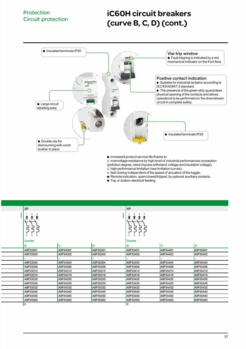
3P 4P
1
2
3
4
5
6
1
2
3
4
5
6
7
8
Courbe Courbe
B C D B C D
A9F53301 A9F54301 A9F55301 A9F53401 A9F54401 A9F55401
A9F53302 A9F54302 A9F55302 A9F53402 A9F54402 A9F55402
- - - - - -
A9F53304 A9F54304 A9F55304 A9F53404 A9F54404 A9F55404
A9F53306 A9F54306 A9F55306 A9F53406 A9F54406 A9F55406
A9F53310 A9F54310 A9F55310 A9F53410 A9F54410 A9F55410
A9F53316 A9F54316 A9F55316 A9F53416 A9F54416 A9F55416
A9F53320 A9F54320 A9F55320 A9F53420 A9F54420 A9F55420
A9F53325 A9F54325 A9F55325 A9F53425 A9F54425 A9F55425
A9F53332 A9F54332 A9F55332 A9F53432 A9F54432 A9F55432
A9F53340 A9F54340 A9F55340 A9F53440 A9F54440 A9F55440
A9F53350 A9F54350 A9F55350 A9F53450 A9F54450 A9F55450
A9F53363 A9F54363 A9F55363 A9F53463 A9F54463 A9F55463
6 8
b Increased product service life thanks to:v overvoltage resistance by high level of industrial performances conception(pollution degree, rated impulse withstand voltage and insulation voltage),
v high performance limitation (see limitation curves), v fast closing independent of the speed of actuation of the toggle.
b Remote indication, open/closed/tripped, by optional auxiliary contacts. b Top or bottom electrical feeding.
Visi-trip windowb Fault tripping is indicated by a red
mechanical indicator on the front face
Positive contact indication b Suitable for industrial isolation according to
IEC/EN 60947-2 standard. b The presence of the green strip guarantees
physical opening of the contacts and allowsoperations to be performed on the downstreamcircuit in complete safety
iC60H circuit breakers
(curve B, C, D) (cont.)
Protection
Circuit protection
E 4 5 0 9 5
E 4 5 0 9 7
b Double clip for dismounting with combbusbar in place
b Insulated terminals IP20
b Large circuitlabelling area
b Insulated terminals IP20
7/16/2019 Acti9 Launch Catalogue
http://slidepdf.com/reader/full/acti9-launch-catalogue 38/12438
iC60H circuit breakers
(curve B, C, D) (cont.)
Protection
Circuit protection
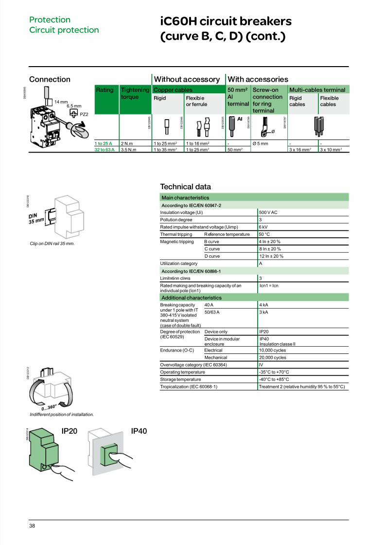
Connection Without accessory With accessories
D B 4
0 5 5 8 5
Rating Tightening
torque
Copper cables 50 mm²
Alterminal
Screw-on
connectionor ring
terminal
Multi-cables terminal
Rigid Flexible
or errule
Rigid
cables
Flexible
cables
1 to 25 A 2 N.m 1 to 25 mm2 1 to 16 mm2 - Ø 5 mm - -32 to 63 A 3.5 N.m 1 to 35 mm2 1 to 25 mm2 50 mm2 3 x 16 mm2 3 x 10 mm2
D B 1 2 2 9 4 5
D B 1 2 2 9 4 6
6.5 mm14 mm
D B 1 2 2 9 3 5
D B 1 1 8 7 8 9
D B 1 1 8 7 8 7
PZ2
Technical dataMain characteristics
According to IEC/EN 60947-2
Insulation voltage (Ui) 500 V AC
Pollution degree 3
Rated impulse withstand voltage (Uimp) 6 kV
Thermal tripping Reference temperature 50 °C
Magnetic tripping B curve 4 In ± 20 %
C curve 8 In ± 20 %
D curve 12 In ± 20 %
Utilization category A
According to IEC/EN 60898-1
Limitation class 3
Rated making and breaking capacity of anindividual pole (Icn1) Icn1 = Icn
Additional characteristics
Breaking capacityunder 1 pole with IT380-415 V isolatedneutral system(case of double fault)
40 A 4 kA
50/63 A 3 kA
Degree of protection(IEC 60529)
Device only IP20
Device in modular enclosure
IP40Insulation classe II
Endurance (O-C) Electrical 10,000 cycles
Mechanical 20,000 cycles
Overvoltage category (IEC 60364) IV
Operating temperature -35°C to +70°C
Storage temperature -40°C to +85°CTropicalization (IEC 60068-1) Treatment 2 (relative humidity 95 % to 55°C)
D B 1 2 3 3 1 0
D B 1 2 3 3 1 2
Clip on DIN rail 35 mm.
Indifferent position of installation.
D B 1 2 3 3 1 4
IP20 IP40
7/16/2019 Acti9 Launch Catalogue
http://slidepdf.com/reader/full/acti9-launch-catalogue 39/12439
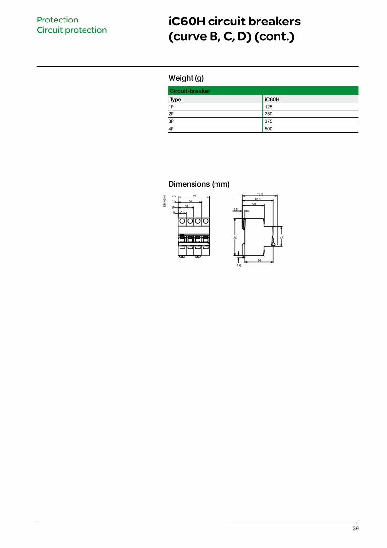
Weight (g)
Circuit-breaker
Type iC60H
1P 125
2P 250
3P 375
4P 500
iC60H circuit breakers
(curve B, C, D) (cont.)
Protection
Circuit protection
Dimensions (mm)
D B 4 0 5 5 8 4 72
54
3650
5.5
85
4.6
64
69.5
78.5
18
4P
3P
2P
1P
45
7/16/2019 Acti9 Launch Catalogue
http://slidepdf.com/reader/full/acti9-launch-catalogue 40/12440
Protect
Circuit protection
Accessory
Padlocking device
b Used to lock the toggle in the "open" or "closed" position by 4 mm diameter padlock (not supplied).
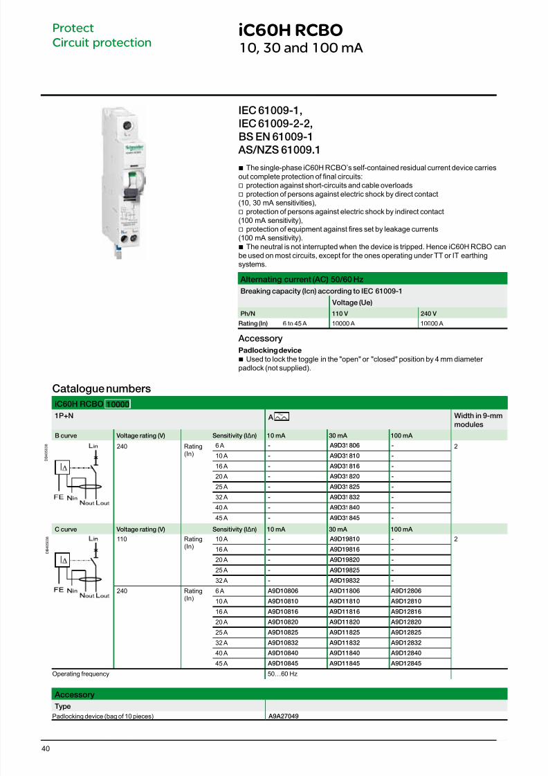
b The single-phase iC60H RCBO’s self-contained residual current device carriesout complete protection of nal circuits:
v protection against short-circuits and cable overloads v protection of persons against electric shock by direct contact
(10, 30 mA sensitivities), v protection of persons against electric shock by indirect contact
(100 mA sensitivity), v protection of equipment against res set by leakage currents
(100 mA sensitivity). b The neutral is not interrupted when the device is tripped. Hence iC60H RCBO can
be used on most circuits, except for the ones operating under TT or IT earthingsystems.
IEC 61009-1,
IEC 61009-2-2,
BS EN 61009-1 AS/NZS 61009.1
Catalogue numbers
iC60H RCBO 100001P+N A Width in 9-mm
modules
B curve Voltage rating (V) Sensitivity (IΔn) 10 mA 30 mA 100 mA
D B 4 0 5 0 3 8 240 Rating
(In)6 A - A9D31806 - 2
10 A - A9D31810 -
16 A - A9D31816 -
20 A - A9D31820 -
25 A - A9D31825 -
32 A - A9D31832 -
40 A - A9D31840 -
45 A - A9D31845 -
C curve Voltage rating (V) Sensitivity (IΔn) 10 mA 30 mA 100 mA
D B 4 0 5 0 3 8 110 Rating
(In)10 A - A9D19810 - 2
16 A - A9D19816 -
20 A - A9D19820 -
25 A - A9D19825 -
32 A - A9D19832 -
240 Rating(In)
6 A A9D10806 A9D11806 A9D12806
10 A A9D10810 A9D11810 A9D12810
16 A A9D10816 A9D11816 A9D12816
20 A A9D10820 A9D11820 A9D12820
25 A A9D10825 A9D11825 A9D12825
32 A A9D10832 A9D11832 A9D12832
40 A A9D10840 A9D11840 A9D12840
45 A A9D10845 A9D11845 A9D12845
Operating frequency 50…60 Hz
Accessory
Type
Padlocking device (bag of 10 pieces) A9A27049
iC60H RCBO10, 30 and 100 mA
Alternating current (AC) 50/60 Hz
Breaking capacity (Icn) according to IEC 61009-1
Voltage (Ue)
Ph/N 110 V 240 V
Rating (In) 6 to 45 A 10000 A 10000 A
7/16/2019 Acti9 Launch Catalogue
http://slidepdf.com/reader/full/acti9-launch-catalogue 41/12441
iC60 RCBO10, 30 and 100 mA
Protect
Circuit protection
Dimensions (mm)
D B 4 0 5 5 6 5
110
1845 19
72
20
45
55 15
5.5
45 19
72
20
45
55 15
5.5
110
36
iC60N RCBO, iC60H RCBO iC60H2 RCBO
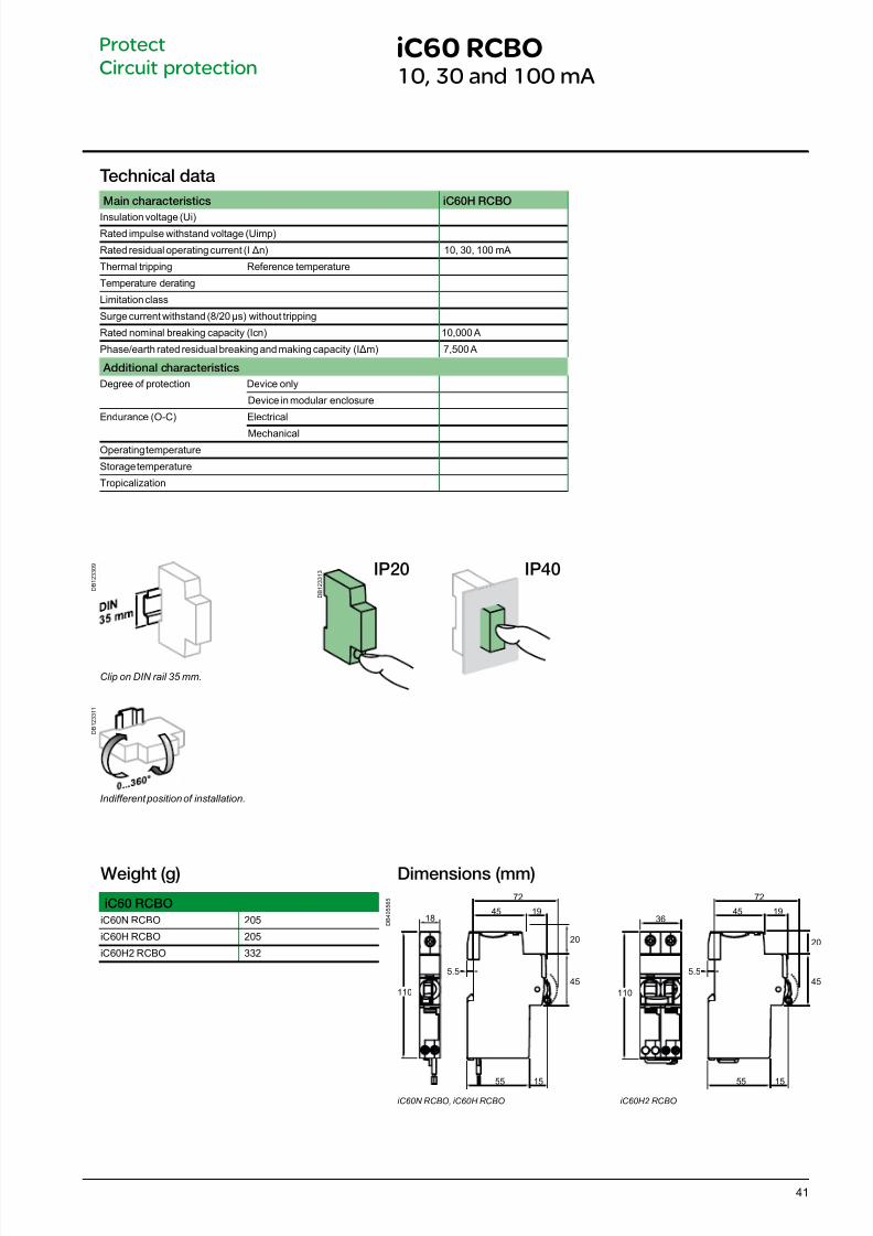
Weight (g)
iC60 RCBO
iC60N RCBO 205
iC60H RCBO 205
iC60H2 RCBO 332
D B 1 2 3 3 0 9
D B 1 2 3 3 1 1
Clip on DIN rail 35 mm.
Indifferent position of installation.
D B 1 2 3 3 1 3 IP20 IP40
Technical data
Main characteristics iC60H RCBO
Insulation voltage (Ui)Rated impulse withstand voltage (Uimp)
Rated residual operating current (IΔn) 10, 30, 100 mA
Thermal tripping Reference temperature
Temperature derating
Limitation class
Surge current withstand (8/20 μs) without tripping
Rated nominal breaking capacity (Icn) 10,000 A
Phase/earth rated residual breaking and making capacity (IΔm) 7,500 A
Additional characteristics
Degree of protection Device only
Device in modular enclosure
Endurance (O-C) Electrical
MechanicalOperating temperature
Storage temperature
Tropicalization
7/16/2019 Acti9 Launch Catalogue
http://slidepdf.com/reader/full/acti9-launch-catalogue 42/12442
D B 4 0 5 5 7 1
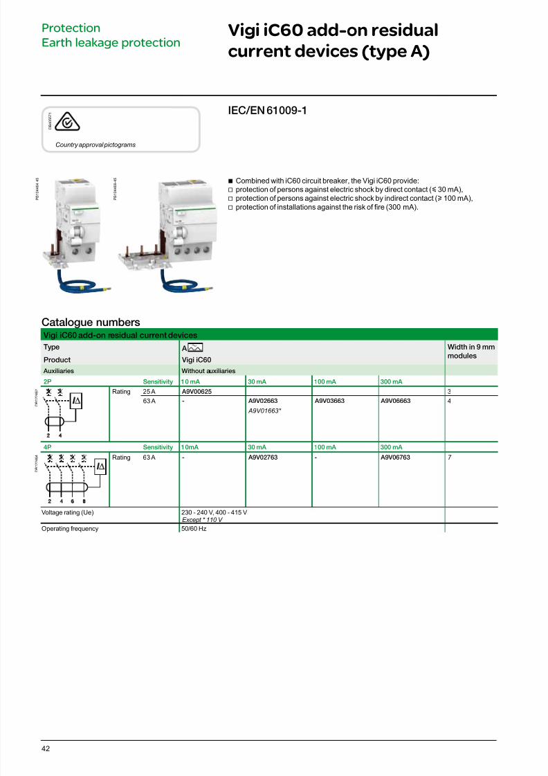
Country approval pictograms
IEC/EN 61009-1
Catalogue numbers Vigi iC60 add-on residual current devices
Type A Width in 9 mm
modulesProduct Vigi iC60
Auxiliaries Without auxiliaries
2P Sensitivity 10 mA 30 mA 100 mA 300 mA
D B 1 2 2 4 6 2 Rating 25 A A9V00625 3
63 A - A9V02663
A9V01663*
A9V03663 A9V06663 4
4P Sensitivity 10mA 30 mA 100 mA 300 mA
D B 1 2 2 4 6 4 Rating 63 A - A9V02763 - A9V06763 7
Voltage rating (Ue) 230 - 240 V, 400 - 415 VExcept * 110 V
Operating frequency 50/60 Hz
Vigi iC60 add-on residual
current devices (type A)
Protection
Earth leakage protection
b Combined with iC60 circuit breaker, the Vigi iC60 provide: v protection of persons against electric shock by direct contact (y 30 mA),
v protection of persons against electric shock by indirect contact (u 100 mA),v protection of installations against the risk of re (300 mA).
P B 1 0 4 4 6 4 - 4 5
P B 1 0 4 4 6 9 - 4 5
7/16/2019 Acti9 Launch Catalogue
http://slidepdf.com/reader/full/acti9-launch-catalogue 43/12443
Vigi iC60 add-on residual
current devices (AC, A, SI types)
(cont.)
Protection
Earth leakage protection
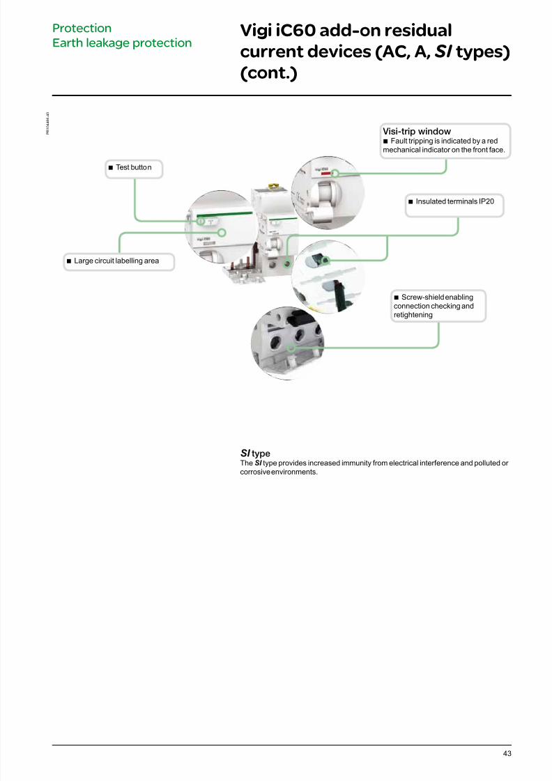
Visi-trip windowb Fault tripping is indicated by a redmechanical indicator on the front face.
b Large circuit labelling area
P B 1 0 4 4 6 6 - 4 0
b Test button
b Insulated terminals IP20
b Screw-shield enablingconnection checking andretightening
SI typeThe SI type provides increased immunity from electrical interference and polluted or corrosive environments.
7/16/2019 Acti9 Launch Catalogue
http://slidepdf.com/reader/full/acti9-launch-catalogue 44/12444
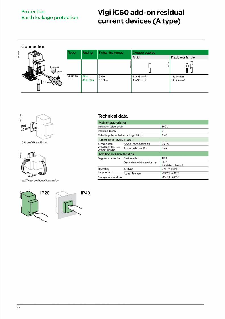
Vigi iC60 add-on residual
current devices (A type)
Protection
Earth leakage protection
Connection
D B 1
2 2 9 4 8
Type Rating Tightening torque Copper cables
Rigid Flexible or errule
Vigi iC60 25 A 2 N.m 1 to 25 mm2 1 to 16 mm2
40 to 63 A 3.5 N.m 1 to 35 mm2 1 to 25 mm2
D B 1 2 2 9 4 5
D B 1 2 2 9 4 6
PZ2
14 mm
6.5 mm
Technical data
Main characteristics
Insulation voltage (Ui) 500 V
Pollution degree 3
Rated impulse withstand voltage (Uimp) 6 kV
According to IEC/EN 61009-1
Surge currentwithstand (8/20 μs)without tripping
A type (no selective s) 250 Â
A type (selective s) 3 kÂ
Additional characteristics
Degree of protection Device only IP20
Device in modular enclosure IP40Insulation classe II
Operatingtemperature
AC type -5°C to +60°C
A and SI types -25°C to +60°C
Storage temperature -40°C to +85°C
D B 1 2 3 3 1 0
D B 1 2 3 3 1 2
Clip on DIN rail 35 mm.
Indifferent position of installation.
D B 1 2 3 3 1 4
IP20 IP40
7/16/2019 Acti9 Launch Catalogue
http://slidepdf.com/reader/full/acti9-launch-catalogue 45/12445
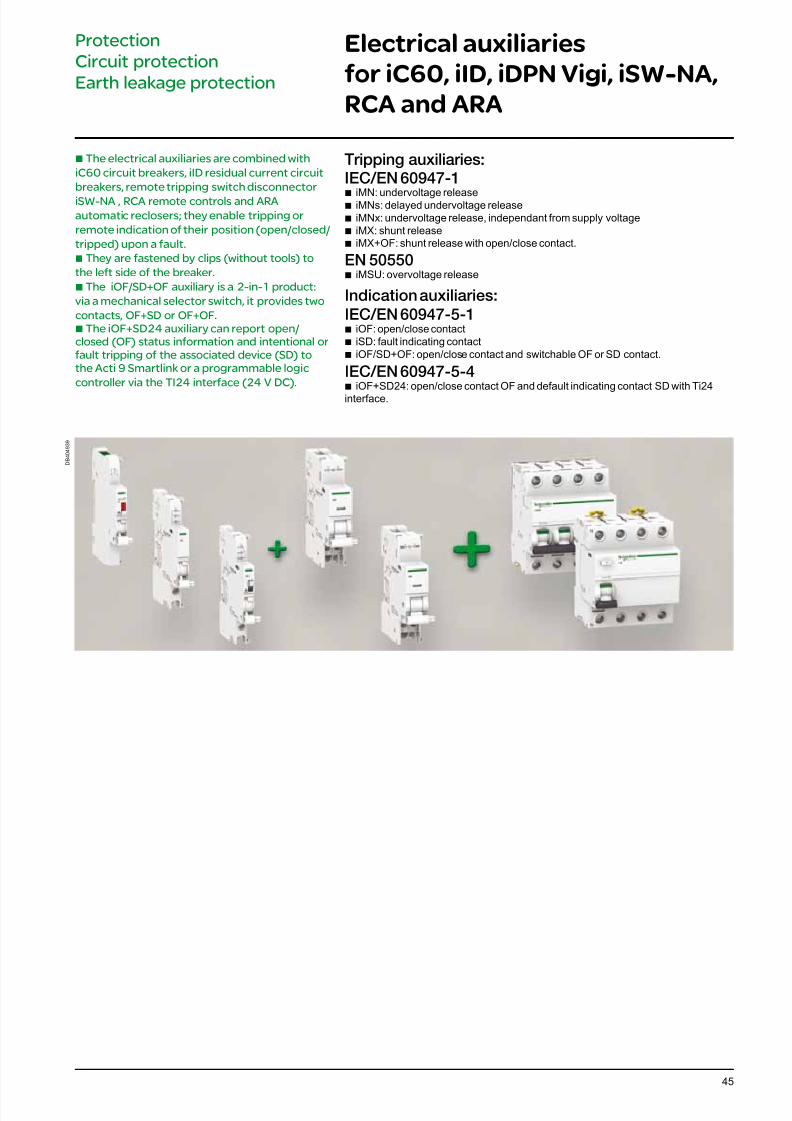
Electrical auxiliaries
for iC60, iID, iDPN Vigi, iSW-NA,
RCA and ARA
Protection
Circuit protection
Earth leakage protection
Tripping auxiliaries:IEC/EN 60947-1
b iMN: undervoltage releaseb iMNs: delayed undervoltage release b iMNx: undervoltage release, independant from supply voltage b iMX: shunt release
b iMX+OF: shunt release with open/close contact.
EN 50550 b iMSU: overvoltage release
Indication auxiliaries:
IEC/EN 60947-5-1 b iOF: open/close contact b iSD: fault indicating contact
b iOF/SD+OF: open/close contact and switchable OF or SD contact.
IEC/EN 60947-5-4 b iOF+SD24: open/close contact OF and default indicating contact SD with Ti24
interface.
b The electrical auxiliaries are combined with
iC60 circuit breakers, iID residual current circuit
breakers, remote tripping switch disconnector
iSW-NA , RCA remote controls and ARA
automatic reclosers; they enable tripping or
remote indication of their position (open/closed/
tripped) upon a fault.
b They are fastened by clips (without tools) to
the left side of the breaker.
b The iOF/SD+OF auxiliary is a 2-in-1 product:
via a mechanical selector switch, it provides two
contacts, OF+SD or OF+OF.b The iOF+SD24 auxiliary can report open/closed (OF) status information and intentional orfault tripping of the associated device (SD) tothe Acti 9 Smartlink or a programmable logic
controller via the TI24 interface (24 V DC).
D B 4 0 4 9 3 9
7/16/2019 Acti9 Launch Catalogue
http://slidepdf.com/reader/full/acti9-launch-catalogue 46/12446
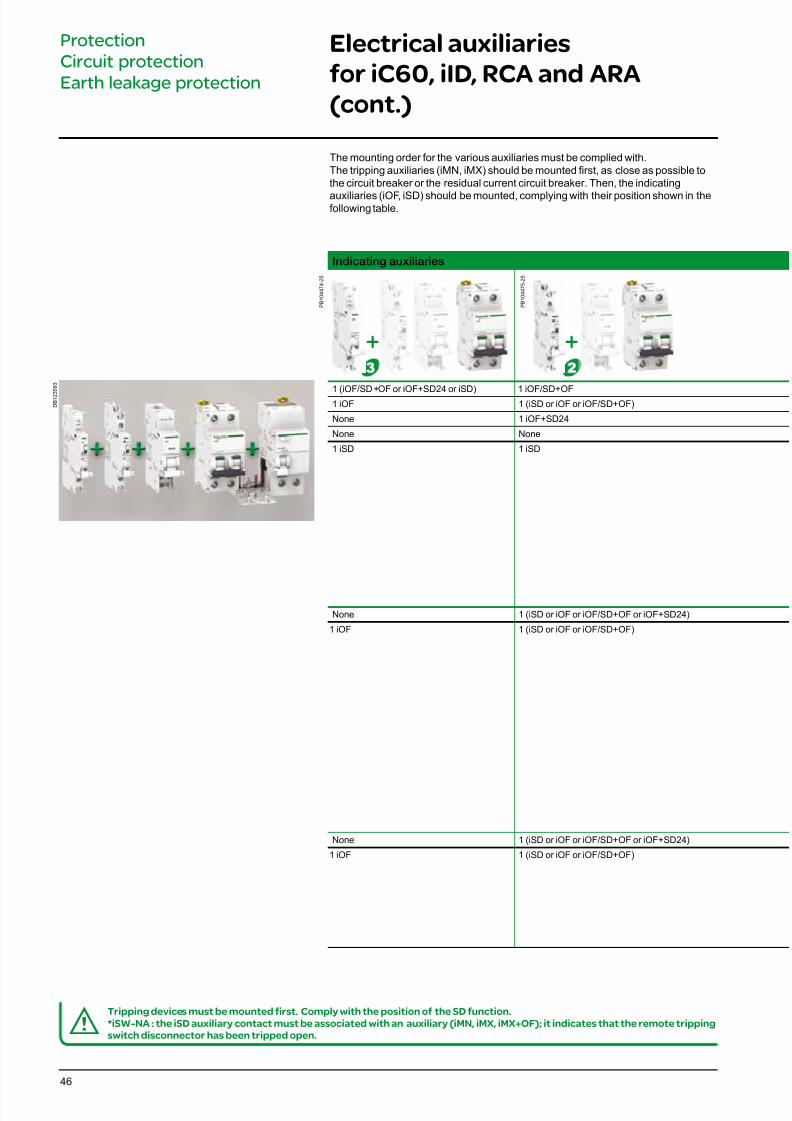
Electrical auxiliaries
for iC60, iID, RCA and ARA
(cont.)
Protection
Circuit protection
Earth leakage protection
dTripping devices must be mounted first. Comply with the position of the SD function.*iSW-NA : the iSD auxiliary contact must be associated with an auxiliary (iMN, iMX, iMX+OF); it indicates that the remote trippingswitch disconnector has been tripped open.
The mounting order for the various auxiliaries must be complied with.The tripping auxiliaries (iMN, iMX) should be mounted rst, as close as possible tothe circuit breaker or the residual current circuit breaker. Then, the indicating
auxiliaries (iOF, iSD) should be mounted, complying with their position shown in thefollowing table.
+ +
D B 1 2 3 5 9 3
Indicating auxiliaries
P B 1 0 4 4 7 4 - 2 5
P B 1 0 4 4 7 5 - 2 5
1 (iOF/SD+OF or iOF+SD24 or iSD) 1 iOF/SD+OF1 iOF 1 (iSD or iOF or iOF/SD+OF)
None 1 iOF+SD24
None None
1 iSD 1 iSD
None 1 (iSD or iOF or iOF/SD+OF or iOF+SD24)
1 iOF 1 (iSD or iOF or iOF/SD+OF)
None 1 (iSD or iOF or iOF/SD+OF or iOF+SD24)
1 iOF 1 (iSD or iOF or iOF/SD+OF)
7/16/2019 Acti9 Launch Catalogue
http://slidepdf.com/reader/full/acti9-launch-catalogue 47/12447
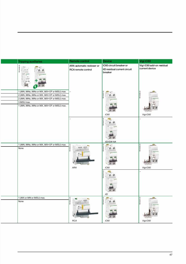
Tripping auxiliaries Remote control Device Vigi iC60
P B 1 0 4 4 9 6 - 2 5
ARA automatic recloser or
RCA remote control
iC60 circuit breaker or
iID residual current circuit
breaker
Vigi iC60 add-on residual
current device
1 (iMN, iMNs, iMNx or iMX, iMX+OF or iMSU) max. –
P B 1 0 4 4 3 7 - 2 5
iC60
P B 1 0 4 4 6 6 - 2 5
Vigi iC60
2 (iMN, iMNs, iMNx or iMX, iMX+OF or iMSU) max.
2 (iMN, iMNs, iMNx or iMX, iMX+OF or iMSU) max.
3 iMSU max.
1 (iMN, iMNs, iMNx or iMX, iMX+OF or iMSU) max.
–
P B 1 0 4 4 7 2 - 2 5
iID/iSW-NA
–
1 (iMN, iMNs, iMNx or iMX, iMX+OF or iMSU) max.
P B 1 0 6 2 5 6 - 2 5
ARA
P B 1 0 4 4 3 7 - 2 5
iC60
P B 1 0 4 4 6 6 - 2 5
Vigi iC60
None
P B 1 0 4 4 7 2 - 2 5
iID
–
1 (iMX or iMN or iMSU) max.
P B 1 0 6 2 5 3 - 2 5
RCA
P B 1 0 4 4 3 7 - 2 5
iC60
P B 1 0 4 4 3 7 - 2 5
Vigi iC60
None
+
7/16/2019 Acti9 Launch Catalogue
http://slidepdf.com/reader/full/acti9-launch-catalogue 48/12448
P B 1 0 4 4 7 7 - 3 5
D B 1 1 8 8 0 4
D B 1 1 8 8 0 5
Electrical auxiliaries
for iC60, iID, iDPN Vigi, iSW-NA,
RCA and ARA (cont.)
Protection
Circuit protection
Earth leakage protection
P B 1 0 4 4 7 8 - 3 5
P B 1 0 4 4 8 0 - 3 5
*(Ua)Voltages measured between the phase and the neutral conductor, at which the iMSU device must control the associated protective device.
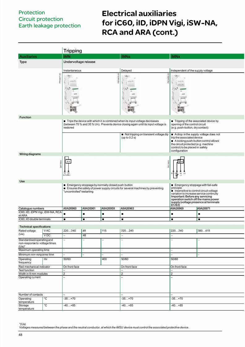
Tripping Auxiliaries iMN iMNs iMNx
Type Undervoltage release
Instantaneous Delayed Independent of the supply voltage
Function
b Trips the device with which it is combined when its input voltage decreases(between 70 % and 35 % Un). Prevents device closing again until its input voltage isrestored
b Tripping of the associated device byopening of the control circuit(e.g. push-button, dry contact)
b Not tripping on transient voltage dip(up to 0.2 s)
b A drop in the supply voltage does nottrip the associated device
b A locking push-button control allowsthe circuit protected (e.g. machinecontrol) to be placed in safetyconguration
Wiring diagrams
U <
E2 N/
L1
L2E1
Useb Emergency stoppage by normally closed push buttonb Ensures the safety of power supply circuits for several machines by preventing"uncontrolled" restarting
b Emergency stoppage with fail-safeprinciple
b Insensitive to control circuit voltagevariation to increase service continuityImportant: Beore any servicingoperation switch o the mains power supply (voltage presence at terminalsE1/E2)
Catalogue numbers A9A26960 A9A26961 A9A26959 A9A26963 A9A26969 A9A26971
iC60, iID, iDPN Vigi, iSW-NA, RCAet ARA
b b b b b b
iC60, iID double terminals b b b b b b
Technical specications
Rated voltage(Ue)
V AC 220…240 48 115 220…240 220…240 380…415
V DC – 48 – –
Standardised operating and
non-response to voltage times(Ua)*
– – – – – –
Maximum operating time – – – – – –
Minimum non-response time – – – – – –
Operatingfrequency
Hz 50/60 400 50/60 50/60
Red mechanical indicator On front face On front face On front faceTest function – – –Width in 9 mm modules 2 2 2Operating current – – –
Number of contacts – – –
Operatingtemperature
°C -35…+70 -35…+70 -35…+70
Storagetemperature
°C -40…+85 -40…+85 -40…+85
7/16/2019 Acti9 Launch Catalogue
http://slidepdf.com/reader/full/acti9-launch-catalogue 49/12449
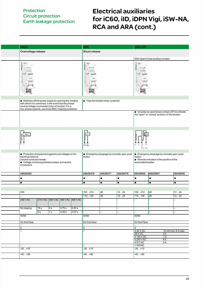
iMSU iMX iMX+OF
Overvoltage release Shunt release
With Open/Close auxiliary contact
b Switches off the power supply by opening the breaker with which it is combined, in the event that the phase/neutral voltage is exceeded (loss of neutral). For afour-phase network, use three iMSU tripping auxiliaries
b Trips the breaker when powered
b Includes an open/close contact (OF) to indicatethe "open" or "closed" position of the breaker
U >
12 C2
11(L/+)
C1
(N/-)
14
U >
b Protection of equipment against overvoltages on theelectrical network(neutral conductor break)
b Voltage monitoring between phase and neutralconductors
b Emergency stoppage by normally open pushbutton
b Emergency stoppage by normally open pushbuttonb Remote indication of the position of theassociated breaker
A9A26500 A9A26476 A9A26477 A9A26478 A9A26946 A9A26947 A9A26948
b b b b b b b
b b b b b b b
230 100…415 48 12…24 100…415 48 12…24
– 110…130 48 12…24 110…130 48 12…24
255 V AC 275 V AC 300 V AC 350 V AC 400 V AC – – – – – –
No tripping 15 s 5 s 0.75 s 0.20 s – – – – – –
3 s 1 s 0.25 s 0.07 s – – – – – –
50/60 50/60 50/60
On front face On front face On front face – – –2 2 2
– – y 24 V DC 10 mA mini, 6 A maxi48 V DC 2 Ay 130 V DC 1 Ay 240 V AC 6 A415 V AC 3 A
– – 1 NO/NC
-35…+70 -35…+70 -35…+70
-40…+85 -40…+85 -40…+85
D B 1 2 3 0 1 2
D B 1 1 8 8 0 8
Electrical auxiliaries
for iC60, iID, iDPN Vigi, iSW-NA,
RCA and ARA (cont.)
Protection
Circuit protection
Earth leakage protection
P B 1 0 4 4 9 6 - 3 5
P B 1 0 4 4 8 1 - 3 5
D B 1 1 8 8 0 6
P B 1 0 4 4 7 9 - 3 5
7/16/2019 Acti9 Launch Catalogue
http://slidepdf.com/reader/full/acti9-launch-catalogue 50/12450
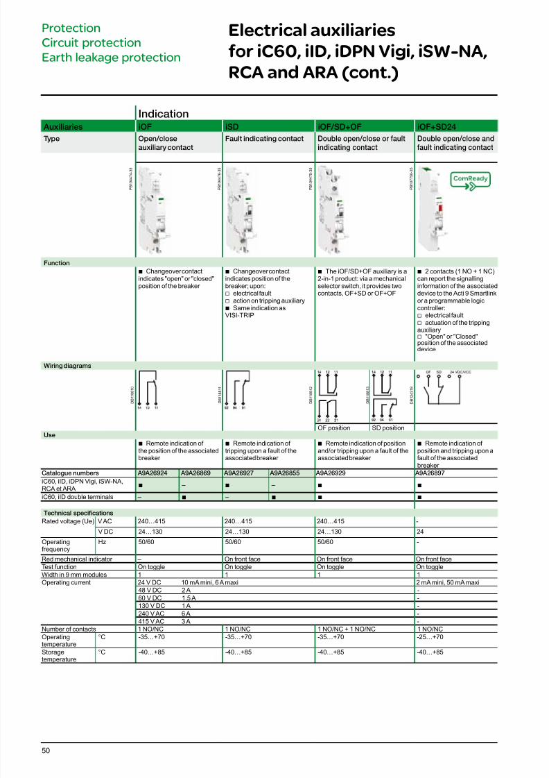
Indication Auxiliaries iOF iSD iOF/SD+OF iOF+SD24
Type Open/closeauxiliary contact
Fault indicating contact Double open/close or faultindicating contact
Double open/close andfault indicating contact
Function
b Changeover contactindicates "open" or "closed"position of the breaker
b Changeover contactindicates position of thebreaker; upon:
v electrical fault v action on tripping auxiliary b Same indication as
VISI-TRIP
b The iOF/SD+OF auxiliary is a2-in-1 product: via a mechanicalselector switch, it provides twocontacts, OF+SD or OF+OF
b 2 contacts (1 NO + 1 NC)can report the signallinginformation of the associateddevice to the Acti 9 Smartlinkor a programmable logiccontroller:v electrical fault
v actuation of the trippingauxiliary
v "Open" or "Closed"position of the associateddevice
Wiring diagrams
OF position SD positionUse
b Remote indication of the position of the associatedbreaker
b Remote indication of tripping upon a fault of theassociated breaker
b Remote indication of positionand/or tripping upon a fault of theassociated breaker
b Remote indication of position and tripping upon afault of the associatedbreaker
Catalogue numbers A9A26924 A9A26869 A9A26927 A9A26855 A9A26929 A9A26897
iC60, iID, iDPN Vigi, iSW-NA,RCA et ARA
b – b – b b
iC60, iID double terminals – b – b b b
Technical specications
Rated voltage (Ue) V AC 240…415 240…415 240…415 -
V DC 24…130 24…130 24…130 24
Operatingfrequency Hz 50/60 50/60 50/60 -
Red mechanical indicator – On front face On front face On front faceTest function On toggle On toggle On toggle On toggleWidth in 9 mm modules 1 1 1 1Operating current 24 V DC 10 mA mini, 6 A maxi 2 mA mini, 50 mA maxi
48 V DC 2 A -60 V DC 1.5 A -130 V DC 1 A -240 V AC 6 A -415 V AC 3 A -
Number of contacts 1 NO/NC 1 NO/NC 1 NO/NC + 1 NO/NC 1 NO/NCOperatingtemperature
°C -35…+70 -35…+70 -35…+70 -25…+70
Storagetemperature
°C -40…+85 -40…+85 -40…+85 -40…+85
D B 1 1 8 8 1 1
D B 1 1 8 8 1 2
D B 1 1 8 8 1 0
D B 1 1 8 8 1 3
D B 1 2 4 3 1 8
P B 1 0 4 4 7 4 - 3 5
P B 1 0 4 4 7 6 - 3 5
P B 1 0 4 4 7 5 - 3 5
P B 1 0 7 7 5 0 - 3 5
Electrical auxiliaries
for iC60, iID, iDPN Vigi, iSW-NA,
RCA and ARA (cont.)
Protection
Circuit protection
Earth leakage protection
7/16/2019 Acti9 Launch Catalogue
http://slidepdf.com/reader/full/acti9-launch-catalogue 51/12451
Electrical auxiliaries
for iC60, iID, iDPN Vigi, iSW-NA,
RCA and ARA (cont.)
Protection
Circuit protection
Earth leakage protection
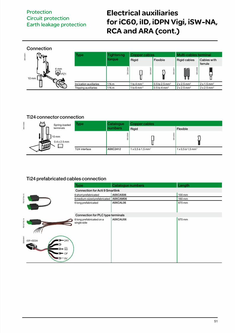
Connection
D B 1
2 3 0 6 1
4 mm
10 mm
PZ1
Type Tightening
torque
Copper cables Multi-cables terminal
Rigid Flexible Rigid cables Cables with
errule
Indication auxiliaries 1 N.m 1 to 4 mm2 0.5 to 2.5 mm2 2 x 2.5 mm2 2 x 1.5 mm2
Tripping auxiliaries 1 N.m 1 to 6 mm2 0.5 to 4 mm2 2 x 2.5 mm2 2 x 2.5 mm2
D B 1 2 2 9 4 5
D B 1 2 3 0 0 7
D B 1 2 3 0 1 1
D B 1 2 3 0 0 8
Ti24 connector connection
D B 1 2 3 5 8 0
Type Catalogue
numbers
Copper cables
Rigid Flexible
Ti24 interface A9XC2412 1 x 0,5 à 1,5 mm2 1 x 0,5 à 1,5 mm2
D B 1 2 2 9 4 5
D B 1 2 3 5 5 3
Spring-loadedterminals
10 mm
0.4 x 2.5 mm
Ti24 preabricated cables connection
Type Catalogue numbers Length
Connection or Acti 9 Smartlink
P B 1 0 7 7 5 4 - 1 0 6 short prefabricated A9XCAS06 100 mm
6 medium-sized prefabricated A9XCAM06 160 mm
6 long prefabricated A9XCAL06 870 mm
Connection or PLC type terminals
P B 1 0 7 7 5 5 - 1 4 6 long prefabricated on a
single side A9XCAU06 870 mm
D B 4 0 4 9 4 1
24V
SD
OF
0V
iOF+SD24
7/16/2019 Acti9 Launch Catalogue
http://slidepdf.com/reader/full/acti9-launch-catalogue 52/12452
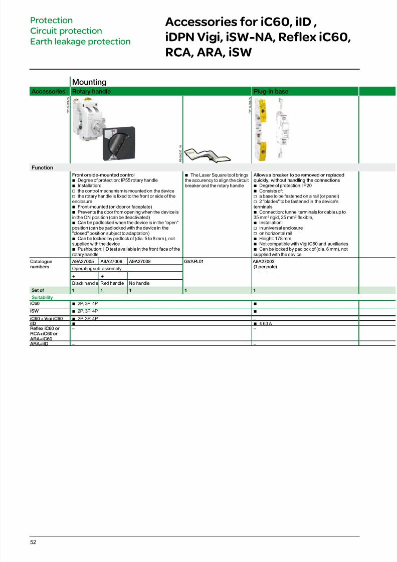
Mounting Accessories Rotary handle Plug-in base
Function
Front or side-mounted control b Degree of protection: IP55 rotary handle b Installation: v the control mechanism is mounted on the device
v the rotary handle is xed to the front or side of theenclosure b Front-mounted (on door or faceplate) b Prevents the door from opening when the device is
in the ON position (can be deactivated) b Can be padlocked when the device is in the "open"
position (can be padlocked with the device in the"closed" position subject to adaptation)b Can be locked by padlock of (dia. 5 to 8 mm), notsupplied with the device
b Pushbutton: iID test available in the front face of therotary handle
b The Laser Square tool bringsthe accurency to align the circuitbreaker and the rotary handle
Allows a breaker to be removed or replacedquickly, without handling the connections
b Degree of protection: IP20 b Consists of:
v a base to be fastened on a rail (or panel) v 2 "blades" to be fastened in the device'sterminals
b Connection: tunnel terminals for cable up to35 mm2 rigid, 25 mm2 exible,b Installation:
v in universal enclosure v on horizontal rail b Height: 178 mm b Not compatible with Vigi iC60 and auxiliaries b Can be locked by padlock of (dia. 6 mm), not
supplied with the device
Cataloguenumbers
A9A27005 A9A27006 A9A27008 GVAPL01 A9A27003(1 per pole)Operating sub-assembly
+ +
Black handle Red handle No handle
Set o 1 1 1 1 1
Suitability
iC60 b 2P, 3P, 4P b
iSW b 2P, 3P, 4P b
iC60 + Vigi iC60 b 2P, 3P, 4P –iID b b y 63 ARefex iC60 or RCA+iC60 or
ARA+iC60
– –
ARA+iID – –
Accessories for iC60, iID ,
iDPN Vigi, iSW-NA, Reflex iC60,
RCA, ARA, iSW
Protection
Circuit protection
Earth leakage protection
P B 1 0 4 5 0 9 - 3 5
P B 1 0 4 5 0 8 - 3 5
P B 1 0 6 2 9 7_
1 0
7/16/2019 Acti9 Launch Catalogue
http://slidepdf.com/reader/full/acti9-launch-catalogue 53/12453
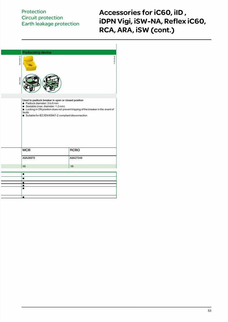
Padlocking device
Used to padlock breaker in open or closed position b Padlock diameter: 3 to 6 mm b Sealable (max. diameter: 1.2 mm) b Locking in ON position does not prevent tripping of the breaker in the event of
faults b Suitable for IEC/EN 60947-2 compliant disconnection
MCB RCBO
A9A26970 A9A27049
10 10
b
b
b b b
b
Accessories for iC60, iID ,
iDPN Vigi, iSW-NA, Reflex iC60,
RCA, ARA, iSW (cont.)
Protection
Circuit protection
Earth leakage protection
P B 1 0 4 4 9 2 - 1 5
P 1 3 5 1 5 9 - 4 0
D B 1 2 3 5 9 9
7/16/2019 Acti9 Launch Catalogue
http://slidepdf.com/reader/full/acti9-launch-catalogue 54/12454
Accessories for iC60, iID ,
iDPN Vigi, iSW-NA, Reflex iC60,
RCA, ARA, iSW (cont.)
Protection
Circuit protection
Earth leakage protection
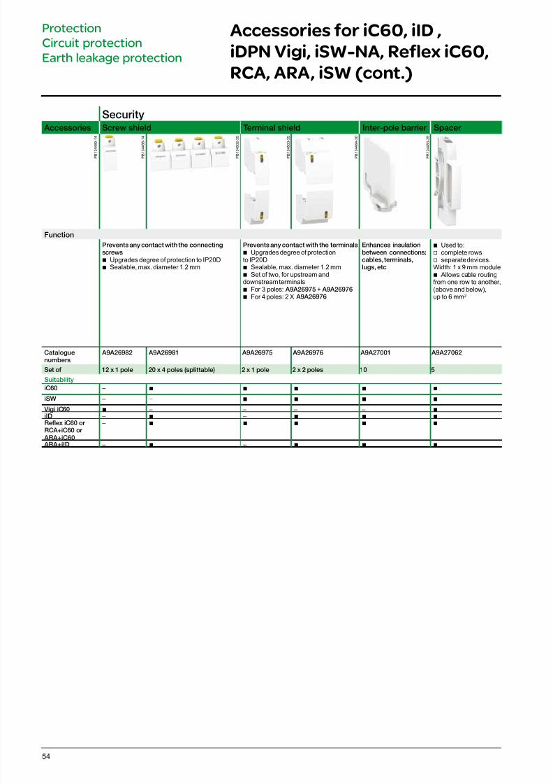
Security Accessories Screw shield Terminal shield Inter-pole barrier Spacer
Function
Prevents any contact with the connectingscrews
b Upgrades degree of protection to IP20D b Sealable, max. diameter 1.2 mm
Prevents any contact with the terminals b Upgrades degree of protection
to IP20D b Sealable, max. diameter 1.2 mm
b Set of two, for upstream anddownstream terminals
b For 3 poles: A9A26975 + A9A26976 b For 4 poles: 2 X A9A26976
Enhances insulationbetween connections:cables, terminals,lugs, etc
b Used to:v complete rowsv separate devices.Width: 1 x 9 mm module
b Allows cable routingfrom one row to another,(above and below),up to 6 mm2
Cataloguenumbers
A9A26982 A9A26981 A9A26975 A9A26976 A9A27001 A9A27062
Set o 12 x 1 pole 20 x 4 poles (splittable) 2 x 1 pole 2 x 2 poles 10 5
Suitability
iC60 – b b b b b
iSW – – b b b b
Vigi iC60 b – – – – b iID – b – b b b Refex iC60 or RCA+iC60 or
ARA+iC60
– b b b b b
ARA+iID – b – b b b
P B 1 0 4 4 8 9 - 1 4
P B 1 0 4 5 0 2 - 3 5
P B 1 0 4 5 0 3 - 3 5
P B 1 0 4 4 8 4 - 3 0
P B 1 0 4 4 8 3 - 3 5
P B 1 0 4 4 8 8 - 1 4
7/16/2019 Acti9 Launch Catalogue
http://slidepdf.com/reader/full/acti9-launch-catalogue 55/124
D B 1 1 8 7 8 0
D B 1 1 8 7 8 1
D B 1 1 8 7 8 3
D B 1 1 8 7 8 7
D B 1 2 2 9 3 5
D B 1 1 8 7 8 9
D B 1 1 8 7 8 5
55
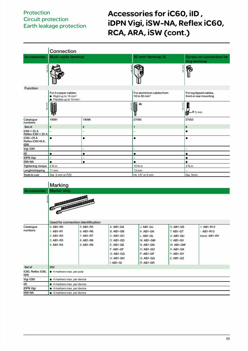
Connection Accessories Multi-cable terminal 50 mm² terminal Al Screw-on connection or
ring terminal
Function
For 3 copper cables:b Rigid up to 16 mm2 b Flexible up to 10 mm2
For aluminium cables rom16 to 50 mm2
For lug tipped cables,ront or rear mounting
5 mm
Catalogue
numbers
19091 19096 27060 27053
Set o 4 3 1 8
iC60 y 25 A Refex iC60 y 25 A
– – – b
iC60 >25 A Refex iC60 40 A,iSW
b b b b
Vigi iC60 – – – –
iID b b b b
iDPN Vigi – – – b iSW-NA b b b b
Tightening torque 2 N.m 10 N.m 2 N.m
Lenght stripping 11 mm 13 mm –
Tools to use Dia. 5 mm or PZ2 Hc 1/5" or 5 mm Dia. 5mm
Marking Accessories Marker strip
Used or connection identication
Catalogue
numbers
0: AB1-R0
1: AB1-R1
2: AB1-R2
3: AB1-R3
4: AB1-R4
5: AB1-R5
6: AB1-R6
7: AB1-R7
8: AB1-R8
9: AB1-R9
A: AB1-GA
B: AB1-GB
C: AB1-GC
D: AB1-GD
E: AB1-GEF: AB1-GF
G: AB1-GG
H: AB1-GH
I: AB1-GI
J: AB1-GJ
K: AB1-GK
L: AB1-GL
M: AB1-GM
N: AB1-GNO: AB1-GO
P: AB1-GP
Q: AB1-GQ
R: AB1-GR
S: AB1-GS
T: AB1-GT
U: AB1-GU
V: AB1-GV
W: AB1-GWX: AB1-GX
Y: AB1-GY
Z: AB1-GZ
+: AB1-R12
-: AB1-R13
blank: AB1-RV
Set o 250
iC60, Refex iC60,iSW
b 4 markers max. per pole
Vigi iC60 b 4 markers max. per device
iID b 4 markers max. per device
iDPN Vigi b 4 markers max. per device
iSW-NA b 4 markers max. per device
Accessories for iC60, iID ,
iDPN Vigi, iSW-NA, Reflex iC60,
RCA, ARA, iSW (cont.)
Protection
Circuit protection
Earth leakage protection
7/16/2019 Acti9 Launch Catalogue
http://slidepdf.com/reader/full/acti9-launch-catalogue 56/12456
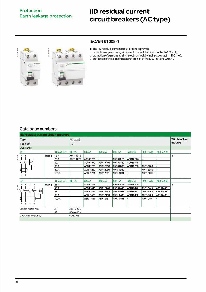
iID residual current
circuit breakers (AC type)
IEC/EN 61008-1
P B 1 0 4 4 7
2 - 4 0
P B 1 0 4 4 7
3 - 4 0
Catalogue numbers
iID residual current circuit breakers
Type AC Width in 9 mm
moduleProduct iID
Auxiliaries
2P Sensitivity 10 mA 30 mA 100 mA 300 mA 500 mA 300 mA
s
500 mA s
D B 1 2 2 4 7 6 Rating 16 A A9R10216 - - - - - - 4
25 A A9R10225 A9R41225 - A9R44225 A9R16225 - -
40 A - A9R41240 A9R12240 A9R44240 A9R16240 - -
63 A - A9R41263 A9R12263 A9R44263 A9R16263 A9R15263 -
80 A - A9R11280 A9R12280 A9R14280 - A9R15280 -
100 A - A9R11291 A9R12291 A9R14291 - A9R15291 -
4P Sensitivity 10 mA 30 mA 100 mA 300 mA 500 mA 300 mA s 500 mA s
D B 1 2 2 4 7 7 Rating 25 A - A9R41425 - A9R44425 A9R16425 - - 8
40 A - A9R41440 A9R12440 A9R44440 A9R16440 A9R15440 A9R17440
63 A - A9R41463 A9R12463 A9R44463 A9R16463 A9R15463 A9R17463
80 A - A9R11480 A9R12480 A9R14480 A9R16480 A9R15480 A9R17480
100 A - A9R11491 A9R12491 A9R14491 - A9R15491 -
Voltage rating (Ue) 2P 230 - 240 V
4P 400 - 415 V
Operating frequency 50/60 Hz
b The iID residual current circuit breakers provide: v protection of persons against electric shock by direct contact (y 30 mA),
v protection of persons against electric shock by indirect contact (u 100 mA),v protection of installations against the risk of re (300 mA or 500 mA).
Protection
Earth leakage protection
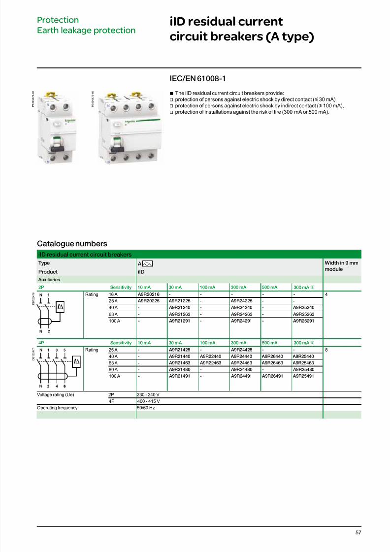
7/16/2019 Acti9 Launch Catalogue
http://slidepdf.com/reader/full/acti9-launch-catalogue 57/12457
Catalogue numbers
iID residual current circuit breakers
Type A Width in 9 mm
moduleProduct iID
Auxiliaries
2P Sensitivity 10 mA 30 mA 100 mA 300 mA 500 mA 300 mA
s
D B 1 2 2 4 7 6 Rating 16 A A9R20216 - - - - - 4
25 A A9R20225 A9R21225 - A9R24225 - -
40 A - A9R21240 - A9R24240 - A9R25240
63 A - A9R21263 - A9R24263 - A9R25263
100 A - A9R21291 - A9R24291 - A9R25291
4P Sensitivity 10 mA 30 mA 100 mA 300 mA 500 mA 300 mA s
D B 1 2 2 4 7 7 Rating 25 A - A9R21425 - A9R24425 - - 8
40 A - A9R21440 A9R22440 A9R24440 A9R26440 A9R25440
63 A - A9R21463 A9R22463 A9R24463 A9R26463 A9R25463
80 A - A9R21480 - A9R24480 - A9R25480
100 A - A9R21491 - A9R24491 A9R26491 A9R25491
Voltage rating (Ue) 2P 230 - 240 V
4P 400 - 415 V
Operating frequency 50/60 Hz
P B 1 0 4 4 7 2 - 4 0
IEC/EN 61008-1
P B 1 0 4 4 7 3 - 4 0
iID residual current
circuit breakers (A type)
b The iID residual current circuit breakers provide: v protection of persons against electric shock by direct contact (y 30 mA),
v protection of persons against electric shock by indirect contact (u 100 mA),v protection of installations against the risk of re (300 mA or 500 mA).
Protection
Earth leakage protection
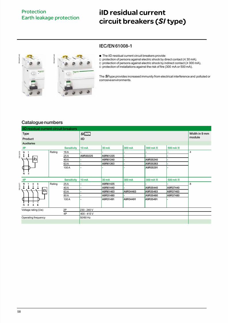
7/16/2019 Acti9 Launch Catalogue
http://slidepdf.com/reader/full/acti9-launch-catalogue 58/12458
iID residual current
circuit breakers (SI type)
Catalogue numbers
iID residual current circuit breakers
Type SI Width in 9 mm
moduleProduct iID
Auxiliaries
2P Sensitivity 10 mA 30 mA 300 mA 300 mA s 500 mA s
D B 1 2 2 4 7 6 Rating 16 A - - - - - 4
25 A A9R30225 A9R61225 - - -
40 A - A9R61240 - A9R35240 -
63 A - A9R61263 - A9R35263 -
100 A - - - A9R35291 -
4P Sensitivity 10 mA 30 mA 300 mA 300 mA s 500 mA s
D B 1 2 2 4 7 7 Rating 25 A - A9R61425 - - - 8
40 A - A9R61440 - A9R35440 A9R37440
63 A - A9R61463 A9R34463 A9R35463 A9R37463
80 A - A9R31480 - A9R35480 A9R37480
100 A - A9R31491 A9R34491 A9R35491 -
Voltage rating (Ue) 2P 230 - 240 V
4P 400 - 415 V
Operating frequency 50/60 Hz
b The iID residual current circuit breakers provide: v protection of persons against electric shock by direct contact (y 30 mA),v protection of persons against electric shock by indirect contact (u 300 mA),v protection of installations against the risk of re (300 mA or 500 mA).
TheSI type provides increased immunity from electrical interference and polluted or corrosive environments.
P B 1 0 4 4 7 2 - 4 0
IEC/EN 61008-1
P B 1 0 4 4 7 3 - 4 0
Protection
Earth leakage protection
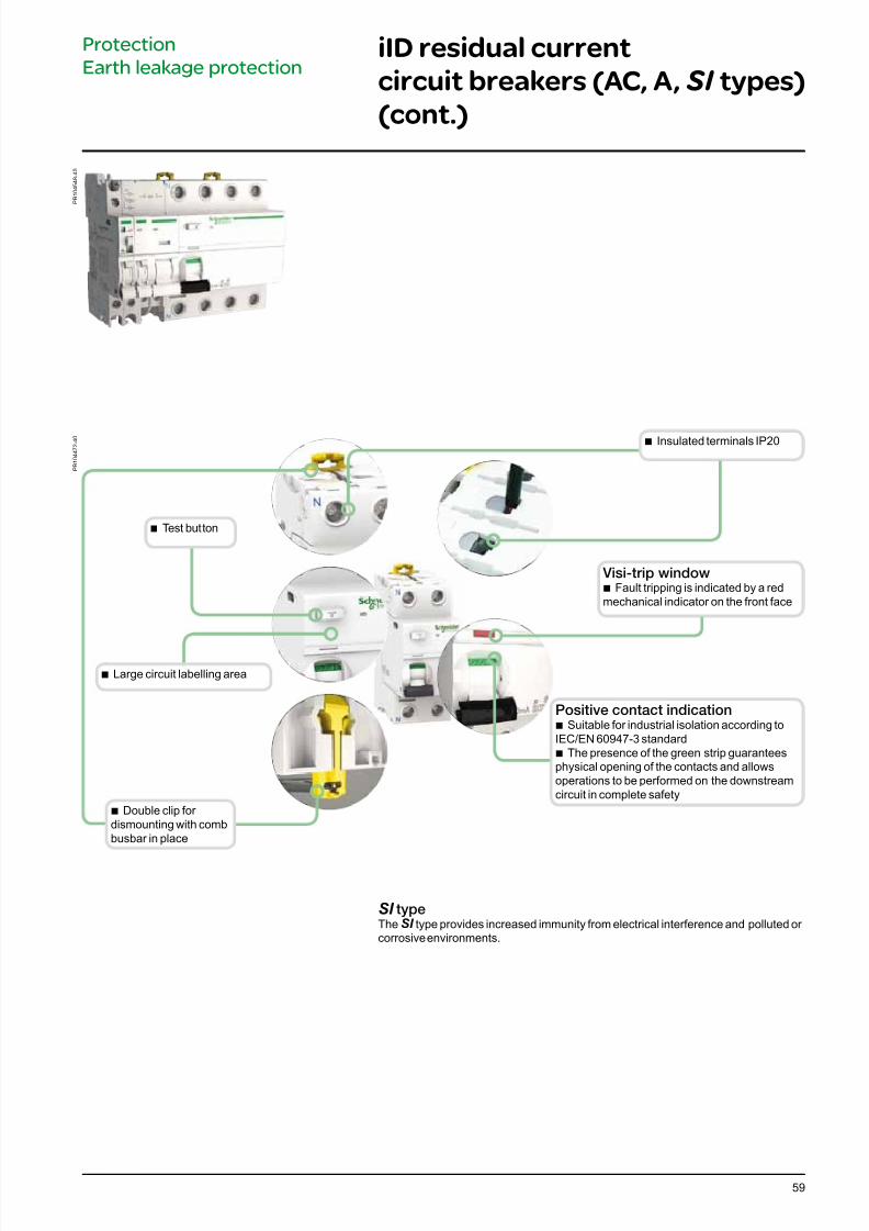
7/16/2019 Acti9 Launch Catalogue
http://slidepdf.com/reader/full/acti9-launch-catalogue 59/12459
Visi-trip window b Fault tripping is indicated by a red
mechanical indicator on the front face
P B 1 0 4 4 7 2 - 4 0
b Double clip for dismounting with combbusbar in place
b Insulated terminals IP20
b Test button
SI typeTheSI type provides increased immunity from electrical interference and polluted or corrosive environments.
Positive contact indication b Suitable for industrial isolation according to
IEC/EN 60947-3 standard b The presence of the green strip guarantees
physical opening of the contacts and allowsoperations to be performed on the downstreamcircuit in complete safety
Protection
Earth leakage protectioniID residual current
circuit breakers (AC, A, SI types)
(cont.)
P B 1 0 4 5 4 8 - 4 0
b Large circuit labelling area
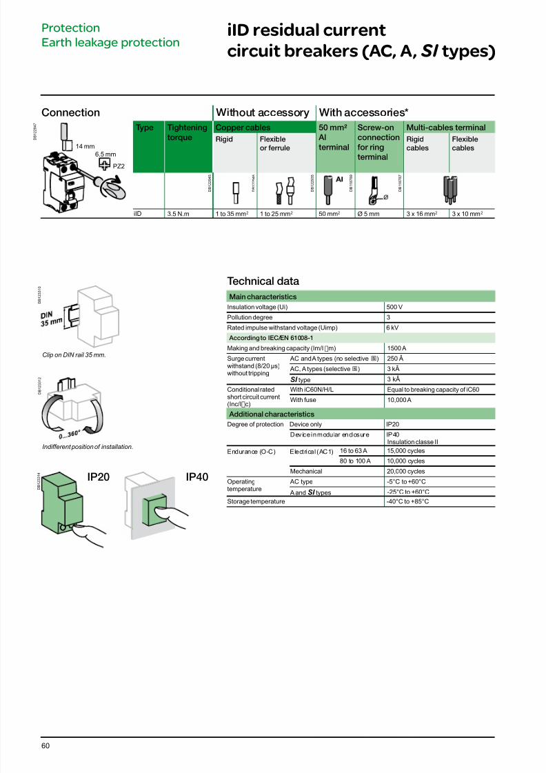
7/16/2019 Acti9 Launch Catalogue
http://slidepdf.com/reader/full/acti9-launch-catalogue 60/12460
Technical data
Main characteristics
Insulation voltage (Ui) 500 V
Pollution degree 3
Rated impulse withstand voltage (Uimp) 6 kV
According to IEC/EN 61008-1
Making and breaking capacity (Im/IDm) 1500 A
Surge currentwithstand (8/20 μs)without tripping
AC and A types (no selective s) 250 Â
AC, A types (selective s) 3 kÂ
SI type 3 kÂ
Conditional ratedshort circuit current
(Inc/IDc)
With iC60N/H/L Equal to breaking capacity of iC60
With fuse 10,000 A
Additional characteristics
Degree of protection Device only IP20
Device in modular enclosure IP40Insulation classe II
Endurance (O-C) Electrical (AC1) 16 to 63 A 15,000 cycles
80 to 100 A 10,000 cycles
Mechanical 20,000 cycles
Operatingtemperature
AC type -5°C to +60°C
A and SI types -25°C to +60°C
Storage temperature -40°C to +85°C
iID residual current
circuit breakers (AC, A, SI types)
Connection Without accessory With accessories*
D B 1
2 2 9 4 7
Type Tightening
torque
Copper cables 50 mm²
Alterminal
Screw-on
connectionor ring
terminal
Multi-cables terminal
Rigid Flexible
or errule
Rigid
cables
Flexible
cables
iID 3.5 N.m 1 to 35 mm2 1 to 25 mm2 50 mm2 Ø 5 mm 3 x 16 mm2 3 x 10 mm2
D B 1 2 2 9 4 5
D B 1 2 2 9 4 6
PZ2
14 mm
D B 1 2 2 9 3 5
D B 1 1 8 7 8 9
D B 1 1 8 7 8 7
Protection
Earth leakage protection
6.5 mm
D B 1 2 3 3 1 0
D B 1 2 3 3 1 2
Clip on DIN rail 35 mm.
Indifferent position of installation.
D B 1 2 3 3 1 4
IP20 IP40
7/16/2019 Acti9 Launch Catalogue
http://slidepdf.com/reader/full/acti9-launch-catalogue 61/12461
Technical advice
Principal of catalogue number Pg 62
Dissipated power, Impedance and Voltage drop Pg 63
Tripping curves Pg 66
Influence of ambient temperature Pg 72
Short-circuit current limiting Pg 79
Direct current applications Pg 97
400 Hz network Pg 111
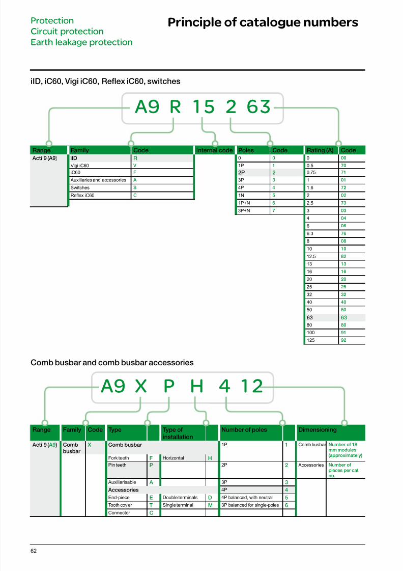
7/16/2019 Acti9 Launch Catalogue
http://slidepdf.com/reader/full/acti9-launch-catalogue 62/12462
Principle of catalogue numbersProtection
Circuit protection
Earth leakage protection
iID, iC60, Vigi iC60, Refex iC60, switches
Range Family Code Internal code Poles Code Rating (A) Code
Acti 9 (A9) iID R 0 0 0 00
Vigi iC60 V 1P 1 0.5 70
iC60 F 2P 2 0.75 71
Auxiliaries and accessories A 3P 3 1 01
Switches S 4P 4 1.6 72
Reex iC60 C 1N 5 2 02
1P+N 6 2.5 73
3P+N 7 3 03
4 04
6 06
6.3 76
8 08
10 10
12.5 82
13 13
16 16
20 20
25 25
32 32
40 40
50 50
63 63
80 80
100 91
125 92
A9 R 15 2 63
Comb busbar and comb busbar accessories
Range Family Code Type Type o
installation
Number o poles Dimensioning
Acti 9 ( A9 ) Comb
busbar
X Comb busbar 1P 1 Comb busbar Number o 18mm modules(approximately)
Fork teeth F Horizontal H
Pin teeth P 2P 2 Accessories Number opieces per cat.no.
Auxiliarisable A 3P 3
Accessories 4P 4
End-piece E Double terminals D 4P balanced, with neutral 5Tooth cover T Single terminal M 3P balanced for single-poles 6
Connector C
A9 X P H 4 12
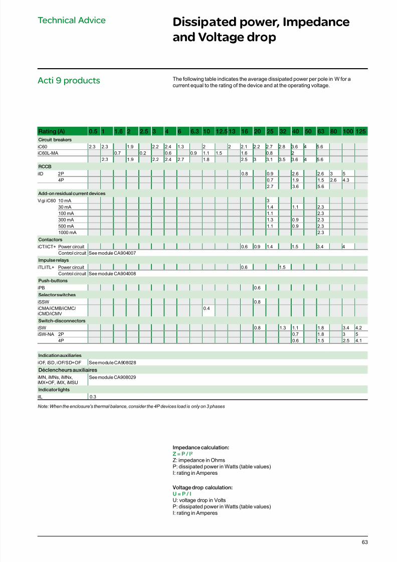
7/16/2019 Acti9 Launch Catalogue
http://slidepdf.com/reader/full/acti9-launch-catalogue 63/12463
Dissipated power, Impedance
and Voltage drop
Technical Advice
Rating (A) 0.5 1 1.6 2 2.5 3 4 6 6.3 10 12.5 13 16 20 25 32 40 50 63 80 100 125
Circuit breakers
iC60 2.3 2.3 1.9 2.2 2.4 1.3 2 2 2.1 2.2 2.7 2.8 3.6 4 5.6iC60L-MA 0.7 0.2 0.6 0.9 1.1 1.5 1.6 0.8 2
2.3 1.9 2.2 2.4 2.7 1.8 2.5 3 3.1 3.5 3.6 4 5.6
RCCB
iID 2P 0.8 0.9 2.6 2.6 3 54P 0.7 1.9 1.5 2.6 4.3
2.7 3.6 5.6
Add-on residual current devices
Vigi iC60 10 mA 330 mA 1.4 1.1 2.3100 mA 1.1 2.3300 mA 1.3 0.9 2.3500 mA 1.1 0.9 2.31000 mA 2.3
Contactors
iCT/iCT+ Power circuit 0.6 0.9 1.4 1.5 3.4 4Control circuit See module CA904007
Impulse relays
iTL/iTL+ Power circuit 0.6 1.5Control circuit See module CA904008
Push-buttons
iPB 0.6
Selector switchesiSSW 0.8iCMA/iCMB/iCMC/iCMD/iCMV
0.4
Switch-disconnectors
iSW 0.8 1.3 1.1 1.8 3.4 4.2iSW-NA 2P 0.7 1.8 3 5
4P 0.6 1.5 2.5 4.1
Indication auxiliaries
iOF, iSD, iOF/SD+OF See module CA908028
Déclencheurs auxiliaires
iMN, iMNs, iMNx,iMX+OF, iMX, iMSU
See module CA908029
Indicator lights
iIL 0.3
Note: When the enclosure's thermal balance, consider the 4P devices load is only on 3 phases
Impedance calculation:
Z = P / I²
Z: impedance in OhmsP: dissipated power in Watts (table values)I: rating in Amperes
Voltage drop calculation:
U = P / I
U: voltage drop in VoltsP: dissipated power in Watts (table values)I: rating in Amperes
The following table indicates the average dissipated power per pole in W for acurrent equal to the rating of the device and at the operating voltage.
Acti 9 products
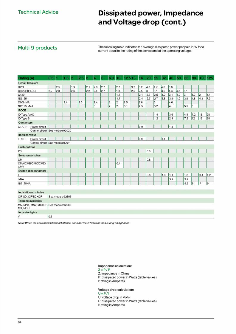
7/16/2019 Acti9 Launch Catalogue
http://slidepdf.com/reader/full/acti9-launch-catalogue 64/12464
Dissipated power, Impedance
and Voltage drop (cont.)
Technical Advice
Rating (A) 0.5 1 1.6 2 2.5 3 4 6 6.3 10 12.5 13 16 20 25 32 40 50 63 80 100 125
Circuit breakers
DPN 2.5 1.9 2.1 2.6 2.7 2.7 3.3 3.2 4.7 4.7 4.6 5.8C60/C60H-DC 2.2 2.3 2.6 2.2 2.4 2.7 1.8 2.5 2.5 3 3.1 3.5 4.3 4.8 6.1C120 1.3 2.1 2.3 2.5 3.2 3.1 3.2 3 3.2 2 4.1NG125 1.7 2.4 2.7 2.7 3.8 3.8 4.2 3.8 4.8 4.3 7.9C60L-MA 2.4 2.5 2.4 3 2 2.5 2.6 3 4.6NG125L-MA 3 2 2 3.1 2.5 3.2 4 5.5 6
RCCB
ID Type A/AC 1.4 3.6 4.4 7.2 18 28ID Type B 1.2 2.9 7.2 12 18 28
Contactors
CT/CT+ Power circuit 0.9 1.4Control circuit See module 92020
Impulse relays
TL/TL+ Power circuit 0.9 1.4Control circuit See module 92011
Push-buttons
PB 0.6
Selector switches
CM 0.8CMA/CMB/CMC/CMD/CMV
0.4
Switch-disconnectors
I 0.8 1.3 1.1 1.8 3.4 4.2I-NA 3.2 3.2
NG125NA 5.5 6 7 9
Indication auxiliaries
OF, SD, OF/SD+OF See module 92605
Tripping auxiliaries
MN, MNs, MNx, MX+OF,MX, MSU
See module 92605
Indicator lights
V 0.3
Note: When the enclosure's thermal balance, consider the 4P devices load is only on 3 phases
Impedance calculation:
Z = P / I²
Z: impedance in OhmsP: dissipated power in Watts (table values)I: rating in Amperes
Voltage drop calculation:
U = P / I
U: voltage drop in VoltsP: dissipated power in Watts (table values)I: rating in Amperes
The following table indicates the average dissipated power per pole in W for acurrent equal to the rating of the device and at the operating voltage.
Multi 9 products
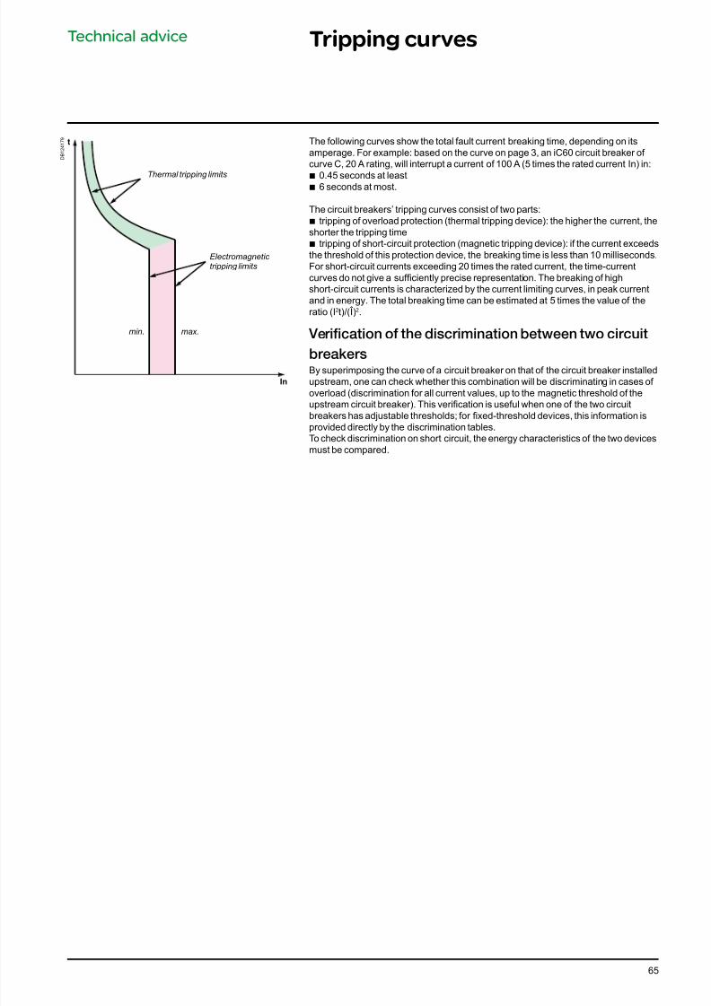
7/16/2019 Acti9 Launch Catalogue
http://slidepdf.com/reader/full/acti9-launch-catalogue 65/12465
Technical advice Tripping curves
In
t
Thermal tripping limits
Electromagnetic tripping limits
min. max.
D B 1 2 4 1 7 9 The following curves show the total fault current breaking time, depending on its
amperage. For example: based on the curve on page 3, an iC60 circuit breaker of curve C, 20 A rating, will interrupt a current of 100 A (5 times the rated current In) in:
b 0.45 seconds at least b 6 seconds at most.
The circuit breakers’ tripping curves consist of two parts:b tripping of overload protection (thermal tripping device): the higher the current, theshorter the tripping time
b tripping of short-circuit protection (magnetic tripping device): if the current exceedsthe threshold of this protection device, the breaking time is less than 10 milliseconds.For short-circuit currents exceeding 20 times the rated current, the time-currentcurves do not give a sufciently precise representation. The breaking of highshort-circuit currents is characterized by the current limiting curves, in peak currentand in energy. The total breaking time can be estimated at 5 times the value of theratio (I2t)/(Î)2.
Verication o the discrimination between two circuit
breakersBy superimposing the curve of a circuit breaker on that of the circuit breaker installedupstream, one can check whether this combination will be discriminating in cases of overload (discrimination for all current values, up to the magnetic threshold of theupstream circuit breaker). This verication is useful when one of the two circuitbreakers has adjustable thresholds; for xed-threshold devices, this information isprovided directly by the discrimination tables.To check discrimination on short circuit, the energy characteristics of the two devicesmust be compared.
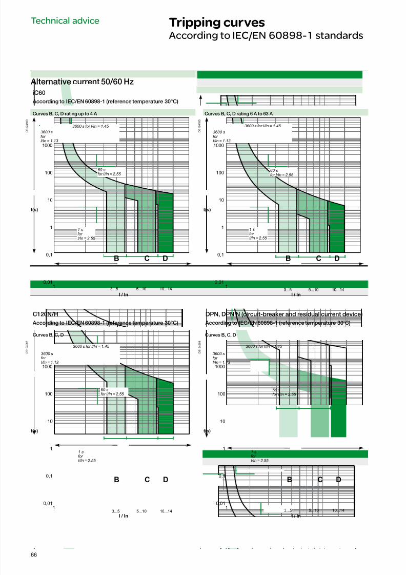
7/16/2019 Acti9 Launch Catalogue
http://slidepdf.com/reader/full/acti9-launch-catalogue 66/12466
Technical advice Tripping curvesAccording to IEC/EN 60898-1 standards
iC60
According to IEC/EN 60898-1 (reerence temperature 30°C)
Curves B, C, D rating up to 4 A Curves B, C, D rating 6 A to 63 A
D B 1 2 4 1 8 0
t(s)
I / In
0,01
0,1
1
10
100
1000
13...5 5...10 10...14
C DB
D B 1 2 4 1 8 5
t(s)
0,01
0,1
1
10
100
1000
I / In
1
C DB
3...5 5...10 10...14
C120N/H DPN, DPN N (circuit-breaker and residual current device)
According to IEC/EN 60898-1 (reerence temperature 30°C) According to IEC/EN 60898-1 (reerence temperature 30°C)
Curves B, C, D Curves B, C, D
D B 1 2 4 2 0 7
t(s)
I / In
0,01
0,1
1
10
100
1000
1
C DB
3...5 5...10 10...14
D B 1 2 4 2 0 8
t(s)
I / In
0,01
0,1
1
10
100
1000
1
C DB
3...5 5...10 10...14
3600 s for I/In = 1.45
3600 sfor I/In = 1.13
60 sfor I/In = 2.55
1 sfor I/In = 2.55
3600 s for I/In = 1.45
3600 sfor I/In = 1.13
60 sfor I/In = 2.55
1 sfor I/In = 2.55
Alternative current 50/60 Hz
3600 s for I/In = 1.45
3600 sfor I/In = 1.13
60 sfor I/In = 2.55
1 sfor I/In = 2.55
3600 s for I/In = 1.45
3600 sfor I/In = 1.13
60 sfor I/In = 2.55
1 sfor I/In = 2.55
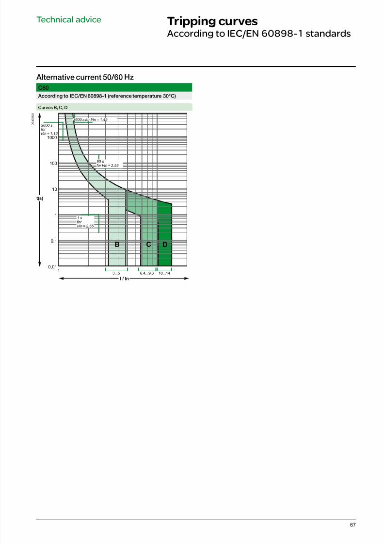
7/16/2019 Acti9 Launch Catalogue
http://slidepdf.com/reader/full/acti9-launch-catalogue 67/12467
Technical advice Tripping curvesAccording to IEC/EN 60898-1 standards
Alternative current 50/60 Hz
C60
According to IEC/EN 60898-1 (reerence temperature 30°C)
Curves B, C, D
D B 4 0 5 8 2 2
t(s)
0,01
0,1
1
10
100
1000
I / In
13...5 6.4...9.6 10...14
C DB
3600 s for I/In = 1.45
3600 sfor I/In = 1.13
60 sfor I/In = 2.55
1 sfor I/In = 2.55
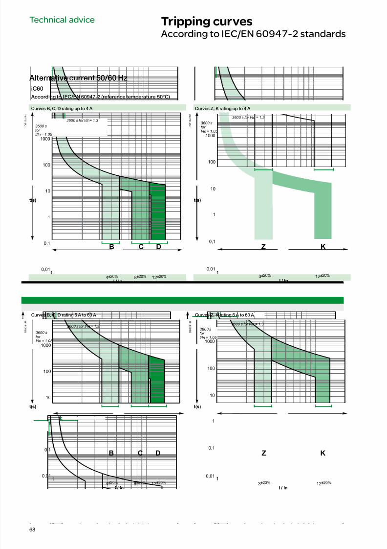
7/16/2019 Acti9 Launch Catalogue
http://slidepdf.com/reader/full/acti9-launch-catalogue 68/12468
Technical advice Tripping curvesAccording to IEC/EN 60947-2 standards
iC60
According to IEC/EN 60947-2 (reerence temperature 50°C)
Curves B, C, D rating up to 4 A Curves Z, K rating up to 4 A
D B 1 2 4 1 8 1
t(s)
I / In
0,01
0,1
1
10
100
1000
14±20% 8±20% 12±20%
C DB
D B 1 2 4 1 8 2
I / In
t(s)
0,01
0,1
1
10
100
1000
KZ
13±20% 12±20%
Curves B, C, D rating 6 A to 63 A Curves Z, K rating 6 A to 63 A
D B 1 2 4 1 8 6
t(s)
0,01
0,1
1
10
100
1000
I / In
1
DB C
4±20% 8±20% 12±20%
D B 1 2 4 1 8 7
I / In
1
t(s)
0,01
0,1
1
10
100
1000
KZ
3±20% 12±20%
3600 s for I/In= 1.33600 s for I/In = 1.3
3600 s for I/In = 1.33600 s for I/In = 1.3
3600 sfor I/In = 1.05
3600 sfor I/In = 1.05
3600 sfor I/In = 1.05
3600 sfor I/In = 1.05
Alternative current 50/60 Hz
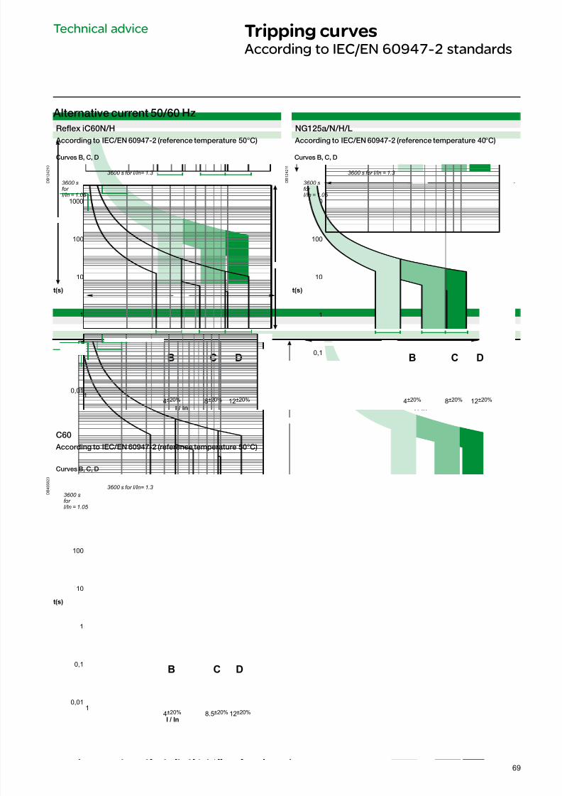
7/16/2019 Acti9 Launch Catalogue
http://slidepdf.com/reader/full/acti9-launch-catalogue 69/12469
Technical advice Tripping curvesAccording to IEC/EN 60947-2 standards
Alternative current 50/60 Hz
Refex iC60N/H NG125a/N/H/L
According to IEC/EN 60947-2 (reerence temperature 50°C) According to IEC/EN 60947-2 (reerence temperature 40°C)
Curves B, C, D Curves B, C, D
D B 1 2 4 2 1 0
t(s)
I / In
0,01
0,1
1
10
100
1000
1
C DB
4±20% 8±20% 12±20%
D B 1 2 4 2 1 1
t(s)
I / In
0,01
0,1
1
10
100
1000
1
C DB
4±20% 8±20% 12±20%
C60
According to IEC/EN 60947-2 (reerence temperature 50°C)
Curves B, C, D
D B 4 0 5 8 2 3
t(s)
0,01
0,1
1
10
100
1000
C DB
I / In
14±20% 8.5±20% 12±20%
3600 s for I/In= 1.3 3600 s for I/In = 1.3
3600 sfor I/In = 1.05
3600 sfor I/In = 1.05
3600 s for I/In= 1.3
3600 sfor I/In = 1.05
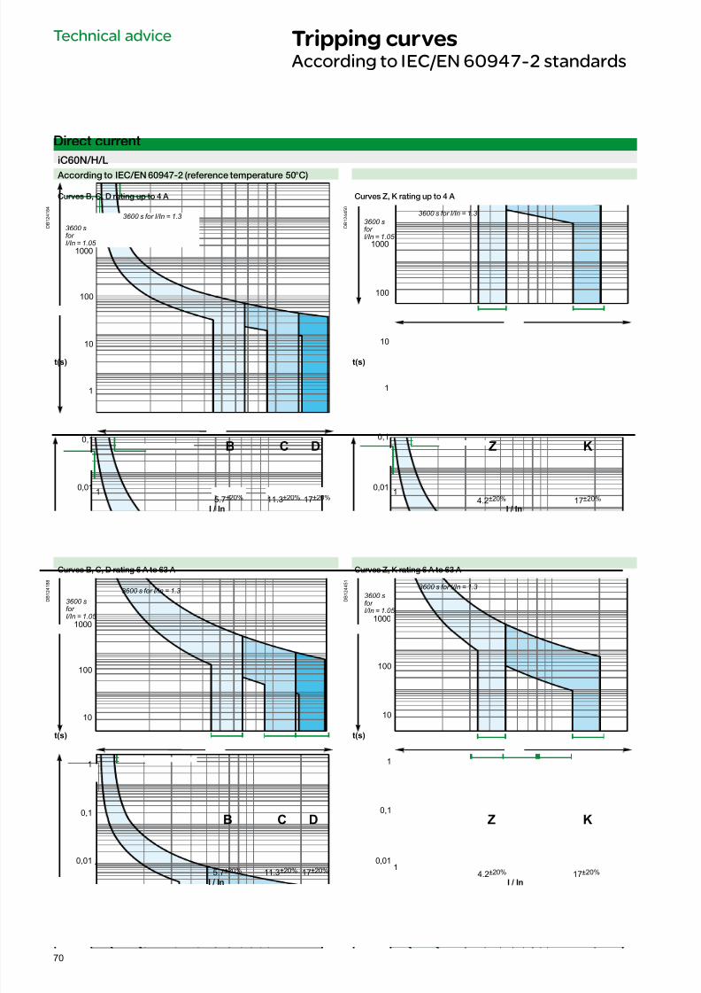
7/16/2019 Acti9 Launch Catalogue
http://slidepdf.com/reader/full/acti9-launch-catalogue 70/12470
Technical advice Tripping curvesAccording to IEC/EN 60947-2 standards
iC60N/H/L
According to IEC/EN 60947-2 (reerence temperature 50°C)
Curves B, C, D rating up to 4 A Curves Z, K rating up to 4 A
D B 1 2 4 1 8 4
t(s)
0,01
0,1
1
10
100
1000
I / In
1
B C D
5.7±20% 11.3±20% 17±20%
D B 1 2 4 4 5 0
I / In
t(s)
0,01
0,1
1
10
100
1000
KZ
14.2±20% 17±20%
Curves B, C, D rating 6 A to 63 A Curves Z, K rating 6 A to 63 A
D B 1 2 4 1 8 8
t(s)
0,01
0,1
1
10
100
1000
I / In
B C D
1 5.7±20% 11.3±20% 17±20%
D B 1 2 4 4 5 1
I / In
t(s)
0,01
0,1
1
10
100
1000
KZ
1 4.2±20% 17±20%
3600 sfor I/In = 1.05
3600 s for I/In = 1.33600 sfor I/In = 1.05
3600 s for I/In = 1.3
3600 s for I/In = 1.3
3600 sfor I/In = 1.05
3600 s for I/In = 1.3
3600 sfor I/In = 1.05
Direct current
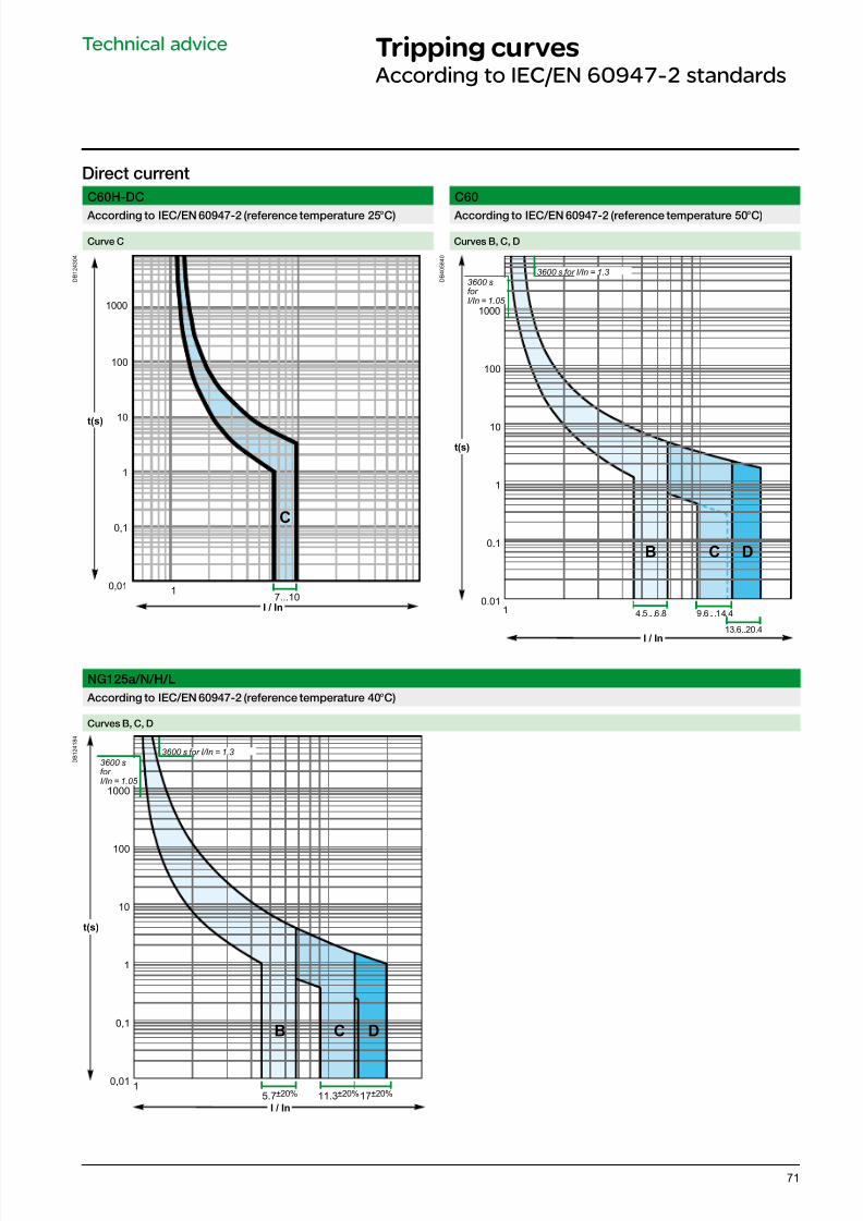
7/16/2019 Acti9 Launch Catalogue
http://slidepdf.com/reader/full/acti9-launch-catalogue 71/12471
Technical advice Tripping curvesAccording to IEC/EN 60947-2 standards
C60H-DC C60
According to IEC/EN 60947-2 (reerence temperature 25°C) According to IEC/EN 60947-2 (reerence temperature 50°C)
Curve C Curves B, C, D
D B 1 2 4 3 0 4
t(s)
I / In
0,01
0,1
1
10
100
1000
1
C
7...10
D B 4 0 5 8 4 0
t(s)
0.01
0.1
1
10
100
1000
I / In
1 4 .5 .. .6 .8 9 .6 .. .1 4. 4
13.6..20.4
B C D
NG125a/N/H/L
According to IEC/EN 60947-2 (reerence temperature 40°C)
Curves B, C, D
D B 1 2 4 1 8 4
t(s)
I / In
0,01
0,1
1
10
100
1000
C DB
15.7±20% 11.3±20%17±20%
3600 sfor I/In = 1.05
3600 s for I/In = 1.3
Direct current
3600 sfor I/In = 1.05
3600 s for I/In = 1.3
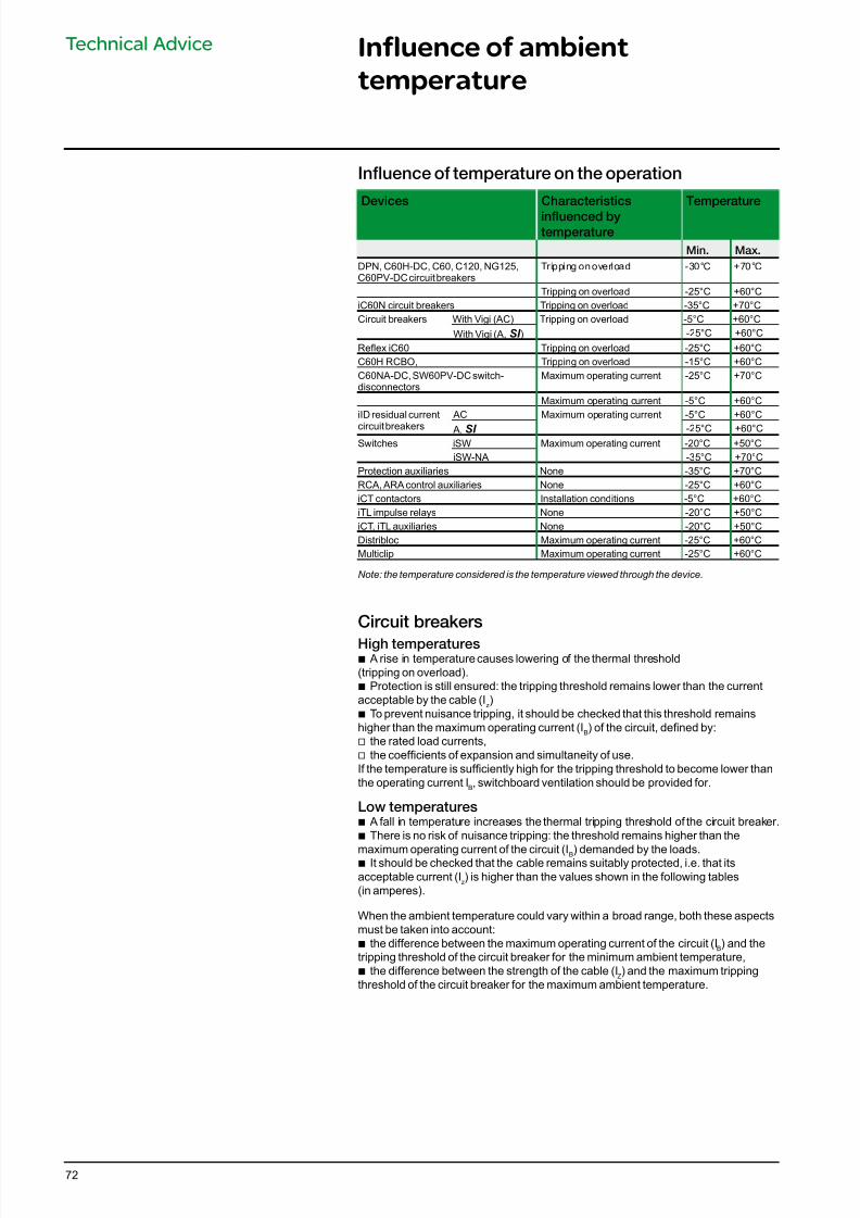
7/16/2019 Acti9 Launch Catalogue
http://slidepdf.com/reader/full/acti9-launch-catalogue 72/12472
Influence of ambient
temperature
Technical Advice
Infuence o temperature on the operation
Devices Characteristics
infuenced bytemperature
Temperature
Min. Max.
DPN, C60H-DC, C60, C120, NG125,C60PV-DC circuit breakers
Tripping on overload -30°C +70°C
Tripping on overload -25°C +60°CiC60N circuit breakers Tripping on overload -35°C +70°CCircuit breakers With Vigi (AC) Tripping on overload -5°C +60°C
With Vigi (A, SI ) -25°C +60°C
Reex iC60 Tripping on overload -25°C +60°CC60H RCBO, Tripping on overload -15°C +60°CC60NA-DC, SW60PV-DC switch-disconnectors
Maximum operating current -25°C +70°C
Maximum operating current -5°C +60°CiID residual current
circuit breakers
AC Maximum operating current -5°C +60°C
A, SI -25°C +60°CSwitches iSW Maximum operating current -20°C +50°C
iSW-NA -35°C +70°CProtection auxiliaries None -35°C +70°CRCA, ARA control auxiliaries None -25°C +60°CiCT contactors Installation conditions -5°C +60°CiTL impulse relays None -20°C +50°CiCT, iTL auxiliaries None -20°C +50°CDistribloc Maximum operating current -25°C +60°CMulticlip Maximum operating current -25°C +60°C
Note: the temperature considered is the temperature viewed through the device.
Circuit breakers
High temperatures b A rise in temperature causes lowering of the thermal threshold
(tripping on overload). b Protection is still ensured: the tripping threshold remains lower than the current
acceptable by the cable (Iz)
b To prevent nuisance tripping, it should be checked that this threshold remainshigher than the maximum operating current (IB) of the circuit, dened by:
v the rated load currents, v the coefcients of expansion and simultaneity of use.
If the temperature is sufciently high for the tripping threshold to become lower thanthe operating current IB, switchboard ventilation should be provided for.
Low temperatures b A fall in temperature increases the thermal tripping threshold of the circuit breaker. b There is no risk of nuisance tripping: the threshold remains higher than the
maximum operating current of the circuit (IB) demanded by the loads. b It should be checked that the cable remains suitably protected, i.e. that itsacceptable current (I
z) is higher than the values shown in the following tables
(in amperes).
When the ambient temperature could vary within a broad range, both these aspectsmust be taken into account:b the difference between the maximum operating current of the circuit (IB) and thetripping threshold of the circuit breaker for the minimum ambient temperature,
b the difference between the strength of the cable (IZ) and the maximum tripping
threshold of the circuit breaker for the maximum ambient temperature.
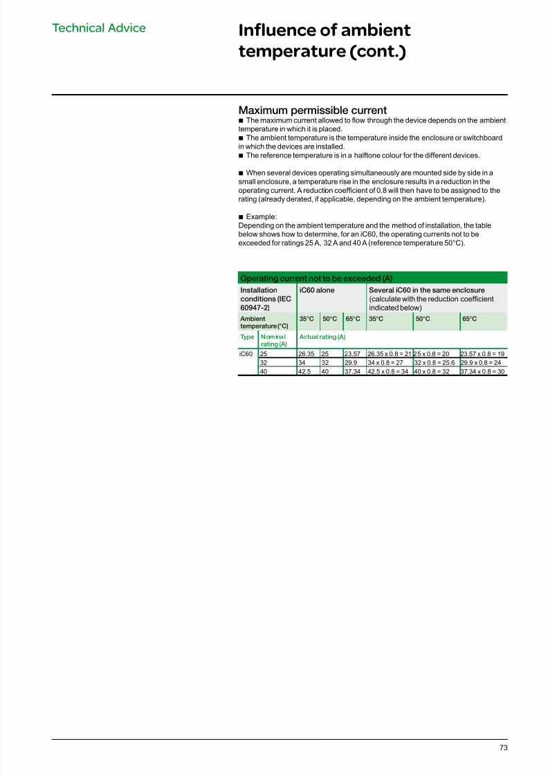
7/16/2019 Acti9 Launch Catalogue
http://slidepdf.com/reader/full/acti9-launch-catalogue 73/12473
Technical Advice Influence of ambient
temperature (cont.)
Maximum permissible current b The maximum current allowed to ow through the device depends on the ambient
temperature in which it is placed.
b The ambient temperature is the temperature inside the enclosure or switchboardin which the devices are installed.b The reference temperature is in a halftone colour for the different devices.
b When several devices operating simultaneously are mounted side by side in asmall enclosure, a temperature rise in the enclosure results in a reduction in theoperating current. A reduction coefcient of 0.8 will then have to be assigned to therating (already derated, if applicable, depending on the ambient temperature).
b Example:Depending on the ambient temperature and the method of installation, the tablebelow shows how to determine, for an iC60, the operating currents not to beexceeded for ratings 25 A, 32 A and 40 A (reference temperature 50°C).
Operating current not to be exceeded (A)
Installation
conditions (IEC
60947-2)
iC60 alone Several iC60 in the same enclosure
(calculate with the reduction coefcientindicated below)
Ambienttemperature (°C)
35°C 50°C 65°C 35°C 50°C 65°C
Type Nominalrating (A)
Actual rating (A)
iC60 25 26.35 25 23.57 26.35 x 0.8 = 21 25 x 0.8 = 20 23.57 x 0.8 = 1932 34 32 29.9 34 x 0.8 = 27 32 x 0.8 = 25.6 29.9 x 0.8 = 2440 42.5 40 37.34 42.5 x 0.8 = 34 40 x 0.8 = 32 37.34 x 0.8 = 30
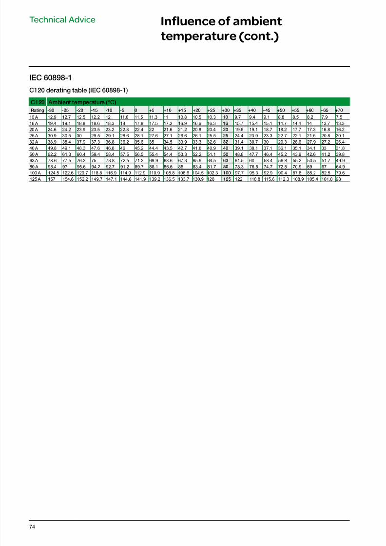
7/16/2019 Acti9 Launch Catalogue
http://slidepdf.com/reader/full/acti9-launch-catalogue 74/12474
C120 derating table (IEC 60898-1)
C120 Ambient temperature (°C)
Rating -30 -25 -20 -15 -10 -5 0 +5 +10 +15 +20 +25 +30 +35 +40 +45 +50 +55 +60 +65 +70
10 A 12.9 12.7 12.5 12.2 12 11.8 11.5 11.3 11 10.8 10.5 10.3 10 9.7 9.4 9.1 8.8 8.5 8.2 7.9 7.516 A 19.4 19.1 18.8 18.6 18.3 18 17.8 17.5 17.2 16.9 16.6 16.3 16 15.7 15.4 15.1 14.7 14.4 14 13.7 13.320 A 24.6 24.2 23.9 23.5 23.2 22.8 22.4 22 21.6 21.2 20.8 20.4 20 19.6 19.1 18.7 18.2 17.7 17.3 16.8 16.225 A 30.9 30.5 30 29.5 29.1 28.6 28.1 27.6 27.1 26.6 26.1 25.5 25 24.4 23.9 23.3 22.7 22.1 21.5 20.8 20.132 A 38.9 38.4 37.9 37.3 36.8 36.2 35.6 35 34.5 33.9 33.3 32.6 32 31.4 30.7 30 29.3 28.6 27.9 27.2 26.440 A 49.8 49.1 48.3 47.6 46.8 46 45.2 44.4 43.5 42.7 41.8 40.9 40 39.1 38.1 37.1 36.1 35.1 34.1 33 31.850 A 62.2 61.3 60.4 59.4 58.4 57.5 56.5 55.4 54.4 53.3 52.2 51.1 50 48.8 47.7 46.4 45.2 43.9 42.6 41.2 39.863 A 78.6 77.5 76.3 75 73.8 72.5 71.3 69.9 68.6 67.3 65.9 64.5 63 61.5 60 58.4 56.8 55.2 53.5 51.7 49.980 A 98.4 97 95.6 94.2 92.7 91.2 89.7 88.1 86.6 85 83.4 81.7 80 78.3 76.5 74.7 72.8 70.9 69 67 64.9100 A 124.5 122.6 120.7 118.8 116.9 114.9 112.9 110.9 108.8 106.6 104.5 102.3 100 97.7 95.3 92.9 90.4 87.8 85.2 82.5 79.6125 A 157 154.6 152.2 149.7 147.1 144.6 141.9 139.2 136.5 133.7 130.9 128 125 122 118.8 115.6 112.3 108.9 105.4 101.8 98
Technical Advice Influence of ambient
temperature (cont.)
IEC 60898-1
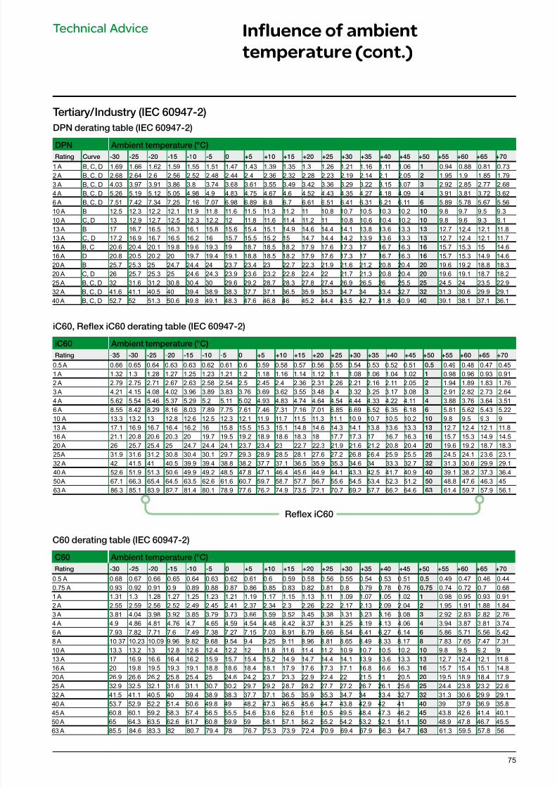
7/16/2019 Acti9 Launch Catalogue
http://slidepdf.com/reader/full/acti9-launch-catalogue 75/12475
Technical Advice Influence of ambient
temperature (cont.)
Tertiary/Industry (IEC 60947-2)
DPN derating table (IEC 60947-2)
DPN Ambient temperature (°C)
Rating Curve -30 -25 -20 -15 -10 -5 0 +5 +10 +15 +20 +25 +30 +35 +40 +45 +50 +55 +60 +65 +70
1 A B, C, D 1.69 1.66 1.62 1.59 1.55 1.51 1.47 1.43 1.39 1.35 1.3 1.26 1.21 1.16 1.11 1.06 1 0.94 0.88 0.81 0.732 A B, C, D 2.68 2.64 2.6 2.56 2.52 2.48 2.44 2.4 2.36 2.32 2.28 2.23 2.19 2.14 2.1 2.05 2 1.95 1.9 1.85 1.793 A B, C, D 4.03 3.97 3.91 3.86 3.8 3.74 3.68 3.61 3.55 3.49 3.42 3.36 3.29 3.22 3.15 3.07 3 2.92 2.85 2.77 2.684 A B, C, D 5.26 5.19 5.12 5.05 4.98 4.9 4.83 4.75 4.67 4.6 4.52 4.43 4.35 4.27 4.18 4.09 4 3.91 3.81 3.72 3.626 A B, C, D 7.51 7.42 7.34 7.25 7.16 7.07 6.98 6.89 6.8 6.7 6.61 6.51 6.41 6.31 6.21 6.11 6 5.89 5.78 5.67 5.5610 A B 12.5 12.3 12.2 12.1 11.9 11.8 11.6 11.5 11.3 11.2 11 10.8 10.7 10.5 10.3 10.2 10 9.8 9.7 9.5 9.310 A C, D 13 12.9 12.7 12.5 12.3 12.2 12 11.8 11.6 11.4 11.2 11 10.8 10.6 10.4 10.2 10 9.8 9.6 9.3 9.113 A B 17 16.7 16.5 16.3 16.1 15.8 15.6 15.4 15.1 14.9 14.6 14.4 14.1 13.8 13.6 13.3 13 12.7 12.4 12.1 11.813 A C, D 17.2 16.9 16.7 16.5 16.2 16 15.7 15.5 15.2 15 14.7 14.4 14.2 13.9 13.6 13.3 13 12.7 12.4 12.1 11.716 A B, C 20.6 20.4 20.1 19.8 19.6 19.3 19 18.7 18.5 18.2 17.9 17.6 17.3 17 16.7 16.3 16 15.7 15.3 15 14.616 A D 20.8 20.5 20.2 20 19.7 19.4 19.1 18.8 18.5 18.2 17.9 17.6 17.3 17 16.7 16.3 16 15.7 15.3 14.9 14.620 A B 25.7 25.3 25 24.7 24.4 24 23.7 23.4 23 22.7 22.3 21.9 21.6 21.2 20.8 20.4 20 19.6 19.2 18.8 18.3
20 A C, D 26 25.7 25.3 25 24.6 24.3 23.9 23.6 23.2 22.8 22.4 22 21.7 21.3 20.8 20.4 20 19.6 19.1 18.7 18.225 A B, C, D 32 31.6 31.2 30.8 30.4 30 29.6 29.2 28.7 28.3 27.8 27.4 26.9 26.5 26 25.5 25 24.5 24 23.5 22.932 A B, C, D 41.6 41.1 40.5 40 39.4 38.9 38.3 37.7 37.1 36.5 35.9 35.3 34.7 34 33.4 32.7 32 31.3 30.6 29.9 29.140 A B, C, D 52.7 52 51.3 50.6 49.8 49.1 48.3 47.6 46.8 46 45.2 44.4 43.5 42.7 41.8 40.9 40 39.1 38.1 37.1 36.1
iC60, Refex iC60 derating table (IEC 60947-2)
iC60 Ambient temperature (°C)
Rating -35 -30 -25 -20 -15 -10 -5 0 +5 +10 +15 +20 +25 +30 +35 +40 +45 +50 +55 +60 +65 +70
0.5 A 0.66 0.65 0.64 0.63 0.63 0.62 0.61 0.6 0.59 0.58 0.57 0.56 0.55 0.54 0.53 0.52 0.51 0.5 0.49 0.48 0.47 0.451 A 1.32 1.3 1.28 1.27 1.25 1.23 1.21 1.2 1.18 1.16 1.14 1.12 1.1 1.08 1.06 1.04 1.02 1 0.98 0.96 0.93 0.912 A 2.79 2.75 2.71 2.67 2.63 2.58 2.54 2.5 2.45 2.4 2.36 2.31 2.26 2.21 2.16 2.11 2.05 2 1.94 1.89 1.83 1.763 A 4.21 4.15 4.08 4.02 3.96 3.89 3.83 3.76 3.69 3.62 3.55 3.48 3.4 3.32 3.25 3.17 3.08 3 2.91 2.82 2.73 2.644 A 5.62 5.54 5.46 5.37 5.29 5.2 5.11 5.02 4.93 4.83 4.74 4.64 4.54 4.44 4.33 4.22 4.11 4 3.88 3.76 3.64 3.516 A 8.55 8.42 8.29 8.16 8.03 7.89 7.75 7.61 7.46 7.31 7.16 7.01 6.85 6.69 6.52 6.35 6.18 6 5.81 5.62 5.43 5.2210 A 13.3 13.2 13 12.8 12.6 12.5 12.3 12.1 11.9 11.7 11.5 11.3 11.1 10.9 10.7 10.5 10.2 10 9.8 9.5 9.3 913 A 17.1 16.9 16.7 16.4 16.2 16 15.8 15.5 15.3 15.1 14.8 14.6 14.3 14.1 13.8 13.6 13.3 13 12.7 12.4 12.1 11.816 A 21.1 20.8 20.6 20.3 20 19.7 19.5 19.2 18.9 18.6 18.3 18 17.7 17.3 17 16.7 16.3 16 15.7 15.3 14.9 14.520 A 26 25.7 25.4 25 24.7 24.4 24.1 23.7 23.4 23 22.7 22.3 21.9 21.6 21.2 20.8 20.4 20 19.6 19.2 18.7 18.325 A 31.9 31.6 31.2 30.8 30.4 30.1 29.7 29.3 28.9 28.5 28.1 27.6 27.2 26.8 26.4 25.9 25.5 25 24.5 24.1 23.6 23.132 A 42 41.5 41 40.5 39.9 39.4 38.8 38.2 37.7 37.1 36.5 35.9 35.3 34.6 34 33.3 32.7 32 31.3 30.6 29.9 29.140 A 52.6 51.9 51.3 50.6 49.9 49.2 48.5 47.8 47.1 46.4 45.6 44.9 44.1 43.3 42.5 41.7 40.9 40 39.1 38.2 37.3 36.450 A 67.1 66.3 65.4 64.5 63.5 62.6 61.6 60.7 59.7 58.7 57.7 56.7 55.6 54.5 53.4 52.3 51.2 50 48.8 47.6 46.3 4563 A 86.3 85.1 83.9 82.7 81.4 80.1 78.9 77.6 76.2 74.9 73.5 72.1 70.7 69.2 67.7 66.2 64.6 63 61.4 59.7 57.9 56.1
Refex iC60
C60 derating table (IEC 60947-2)
C60 Ambient temperature (°C)
Rating -30 -25 -20 -15 -10 -5 0 +5 +10 +15 +20 +25 +30 +35 +40 +45 +50 +55 +60 +65 +70
0.5 A 0.68 0.67 0.66 0.65 0.64 0.63 0.62 0.61 0.6 0.59 0.58 0.56 0.55 0.54 0.53 0.51 0.5 0.49 0.47 0.46 0.440.75 A 0.93 0.92 0.91 0.9 0.89 0.88 0.87 0.86 0.85 0.83 0.82 0.81 0.8 0.79 0.78 0.76 0.75 0.74 0.72 0.7 0.681 A 1.31 1.3 1.28 1.27 1.25 1.23 1.21 1.19 1.17 1.15 1.13 1.11 1.09 1.07 1.05 1.02 1 0.98 0.95 0.93 0.912 A 2.55 2.59 2.56 2.52 2.49 2.45 2.41 2.37 2.34 2.3 2.26 2.22 2.17 2.13 2.09 2.04 2 1.95 1.91 1.88 1.843 A 3.81 4.04 3.98 3.92 3.85 3.79 3.73 3.66 3.59 3.52 3.45 3.38 3.31 3.23 3.16 3.08 3 2.92 2.83 2.82 2.764 A 4.9 4.86 4.81 4.76 4.7 4.65 4.59 4.54 4.48 4.42 4.37 4.31 4.25 4.19 4.13 4.06 4 3.94 3.87 3.81 3.746 A 7.93 7.82 7.71 7.6 7.49 7.38 7.27 7.15 7.03 6.91 6.79 6.66 6.54 6.41 6.27 6.14 6 5.86 5.71 5.56 5.428 A 10.37 10.23 10.09 9.96 9.82 9.68 9.54 9.4 9.25 9.11 8.96 8.81 8.65 8.49 8.33 8.17 8 7.83 7.65 7.47 7.3110 A 13.3 13.2 13 12.8 12.6 12.4 12.2 12 11.8 11.6 11.4 11.2 10.9 10.7 10.5 10.2 10 9.8 9.5 9.2 913 A 17 16.9 16.6 16.4 16.2 15.9 15.7 15.4 15.2 14.9 14.7 14.4 14.1 13.9 13.6 13.3 13 12.7 12.4 12.1 11.816 A 20 19.8 19.5 19.3 19.1 18.8 18.6 18.4 18.1 17.9 17.6 17.3 17.1 16.8 16.6 16.3 16 15.7 15.4 15.1 14.820 A 26.9 26.6 26.2 25.8 25.4 25 24.6 24.2 23.7 23.3 22.9 22.4 22 21.5 21 20.5 20 19.5 18.9 18.4 17.9
25 A 32.9 32.5 32.1 31.6 31.1 30.7 30.2 29.7 29.2 28.7 28.2 27.7 27.2 26.7 26.1 25.625
24.4 23.8 23.2 22.632 A 41.5 41.1 40.5 40 39.4 38.9 38.3 37.7 37.1 36.5 35.9 35.3 34.7 34 33.4 32.7 32 31.3 30.6 29.9 29.140 A 53.7 52.9 52.2 51.4 50.6 49.8 49 48.2 47.3 46.5 45.6 44.7 43.8 42.9 42 41 40 39 37.9 36.9 35.845 A 60.8 60.1 59.2 58.3 57.4 56.5 55.5 54.6 53.6 52.6 51.6 50.5 49.5 48.4 47.3 46.2 45 43.8 42.6 41.4 40.150 A 65 64.3 63.5 62.6 61.7 60.8 59.9 59 58.1 57.1 56.2 55.2 54.2 53.2 52.1 51.1 50 48.9 47.8 46.7 45.563 A 85.5 84.6 83.3 82 80.7 79.4 78 76.7 75.3 73.9 72.4 70.9 69.4 67.9 66.3 64.7 63 61.3 59.5 57.8 56
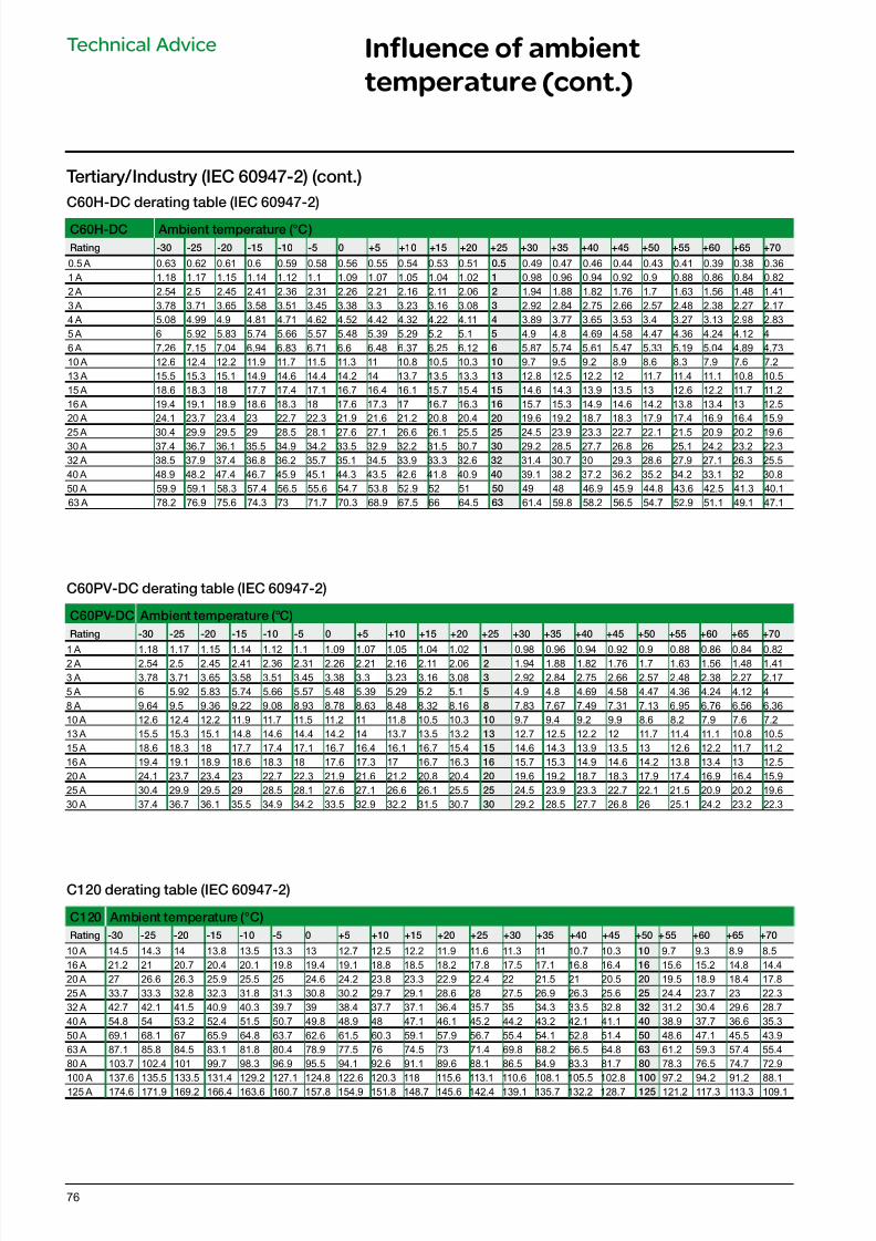
7/16/2019 Acti9 Launch Catalogue
http://slidepdf.com/reader/full/acti9-launch-catalogue 76/12476
C60H-DC derating table (IEC 60947-2)
C60H-DC Ambient temperature (°C)
Rating -30 -25 -20 -15 -10 -5 0 +5 +10 +15 +20 +25 +30 +35 +40 +45 +50 +55 +60 +65 +70
0.5 A 0.63 0.62 0.61 0.6 0.59 0.58 0.56 0.55 0.54 0.53 0.51 0.5 0.49 0.47 0.46 0.44 0.43 0.41 0.39 0.38 0.361 A 1.18 1.17 1.15 1.14 1.12 1.1 1.09 1.07 1.05 1.04 1.02 1 0.98 0.96 0.94 0.92 0.9 0.88 0.86 0.84 0.822 A 2.54 2.5 2.45 2.41 2.36 2.31 2.26 2.21 2.16 2.11 2.06 2 1.94 1.88 1.82 1.76 1.7 1.63 1.56 1.48 1.413 A 3.78 3.71 3.65 3.58 3.51 3.45 3.38 3.3 3.23 3.16 3.08 3 2.92 2.84 2.75 2.66 2.57 2.48 2.38 2.27 2.174 A 5.08 4.99 4.9 4.81 4.71 4.62 4.52 4.42 4.32 4.22 4.11 4 3.89 3.77 3.65 3.53 3.4 3.27 3.13 2.98 2.835 A 6 5.92 5.83 5.74 5.66 5.57 5.48 5.39 5.29 5.2 5.1 5 4.9 4.8 4.69 4.58 4.47 4.36 4.24 4.12 46 A 7.26 7.15 7.04 6.94 6.83 6.71 6.6 6.48 6.37 6.25 6.12 6 5.87 5.74 5.61 5.47 5.33 5.19 5.04 4.89 4.7310 A 12.6 12.4 12.2 11.9 11.7 11.5 11.3 11 10.8 10.5 10.3 10 9.7 9.5 9.2 8.9 8.6 8.3 7.9 7.6 7.213 A 15.5 15.3 15.1 14.9 14.6 14.4 14.2 14 13.7 13.5 13.3 13 12.8 12.5 12.2 12 11.7 11.4 11.1 10.8 10.515 A 18.6 18.3 18 17.7 17.4 17.1 16.7 16.4 16.1 15.7 15.4 15 14.6 14.3 13.9 13.5 13 12.6 12.2 11.7 11.216 A 19.4 19.1 18.9 18.6 18.3 18 17.6 17.3 17 16.7 16.3 16 15.7 15.3 14.9 14.6 14.2 13.8 13.4 13 12.520 A 24.1 23.7 23.4 23 22.7 22.3 21.9 21.6 21.2 20.8 20.4 20 19.6 19.2 18.7 18.3 17.9 17.4 16.9 16.4 15.9
25 A 30.4 29.9 29.5 29 28.5 28.1 27.6 27.1 26.6 26.1 25.5 25 24.5 23.9 23.3 22.7 22.1 21.5 20.9 20.2 19.630 A 37.4 36.7 36.1 35.5 34.9 34.2 33.5 32.9 32.2 31.5 30.7 30 29.2 28.5 27.7 26.8 26 25.1 24.2 23.2 22.332 A 38.5 37.9 37.4 36.8 36.2 35.7 35.1 34.5 33.9 33.3 32.6 32 31.4 30.7 30 29.3 28.6 27.9 27.1 26.3 25.540 A 48.9 48.2 47.4 46.7 45.9 45.1 44.3 43.5 42.6 41.8 40.9 40 39.1 38.2 37.2 36.2 35.2 34.2 33.1 32 30.850 A 59.9 59.1 58.3 57.4 56.5 55.6 54.7 53.8 52.9 52 51 50 49 48 46.9 45.9 44.8 43.6 42.5 41.3 40.163 A 78.2 76.9 75.6 74.3 73 71.7 70.3 68.9 67.5 66 64.5 63 61.4 59.8 58.2 56.5 54.7 52.9 51.1 49.1 47.1
C120 derating table (IEC 60947-2)
C120 Ambient temperature (°C)
Rating -30 -25 -20 -15 -10 -5 0 +5 +10 +15 +20 +25 +30 +35 +40 +45 +50 +55 +60 +65 +70
10 A 14.5 14.3 14 13.8 13.5 13.3 13 12.7 12.5 12.2 11.9 11.6 11.3 11 10.7 10.3 10 9.7 9.3 8.9 8.516 A 21.2 21 20.7 20.4 20.1 19.8 19.4 19.1 18.8 18.5 18.2 17.8 17.5 17.1 16.8 16.4 16 15.6 15.2 14.8 14.420 A 27 26.6 26.3 25.9 25.5 25 24.6 24.2 23.8 23.3 22.9 22.4 22 21.5 21 20.5 20 19.5 18.9 18.4 17.825 A 33.7 33.3 32.8 32.3 31.8 31.3 30.8 30.2 29.7 29.1 28.6 28 27.5 26.9 26.3 25.6 25 24.4 23.7 23 22.332 A 42.7 42.1 41.5 40.9 40.3 39.7 39 38.4 37.7 37.1 36.4 35.7 35 34.3 33.5 32.8 32 31.2 30.4 29.6 28.740 A 54.8 54 53.2 52.4 51.5 50.7 49.8 48.9 48 47.1 46.1 45.2 44.2 43.2 42.1 41.1 40 38.9 37.7 36.6 35.350 A 69.1 68.1 67 65.9 64.8 63.7 62.6 61.5 60.3 59.1 57.9 56.7 55.4 54.1 52.8 51.4 50 48.6 47.1 45.5 43.963 A 87.1 85.8 84.5 83.1 81.8 80.4 78.9 77.5 76 74.5 73 71.4 69.8 68.2 66.5 64.8 63 61.2 59.3 57.4 55.480 A 103.7 102.4 101 99.7 98.3 96.9 95.5 94.1 92.6 91.1 89.6 88.1 86.5 84.9 83.3 81.7 80 78.3 76.5 74.7 72.9100 A 137.6 135.5 133.5 131.4 129.2 127.1 124.8 122.6 120.3 118 115.6 113.1 110.6 108.1 105.5 102.8 100 97.2 94.2 91.2 88.1125 A 174.6 171.9 169.2 166.4 163.6 160.7 157.8 154.9 151.8 148.7 145.6 142.4 139.1 135.7 132.2 128.7 125 121.2 117.3 113.3 109.1
Tertiary/Industry (IEC 60947-2) (cont.)
Technical Advice Influence of ambient
temperature (cont.)
C60PV-DC derating table (IEC 60947-2)
C60PV-DC Ambient temperature (°C)
Rating -30 -25 -20 -15 -10 -5 0 +5 +10 +15 +20 +25 +30 +35 +40 +45 +50 +55 +60 +65 +70
1 A 1.18 1.17 1.15 1.14 1.12 1.1 1.09 1.07 1.05 1.04 1.02 1 0.98 0.96 0.94 0.92 0.9 0.88 0.86 0.84 0.822 A 2.54 2.5 2.45 2.41 2.36 2.31 2.26 2.21 2.16 2.11 2.06 2 1.94 1.88 1.82 1.76 1.7 1.63 1.56 1.48 1.413 A 3.78 3.71 3.65 3.58 3.51 3.45 3.38 3.3 3.23 3.16 3.08 3 2.92 2.84 2.75 2.66 2.57 2.48 2.38 2.27 2.175 A 6 5.92 5.83 5.74 5.66 5.57 5.48 5.39 5.29 5.2 5.1 5 4.9 4.8 4.69 4.58 4.47 4.36 4.24 4.12 48 A 9.64 9.5 9.36 9.22 9.08 8.93 8.78 8.63 8.48 8.32 8.16 8 7.83 7.67 7.49 7.31 7.13 6.95 6.76 6.56 6.3610 A 12.6 12.4 12.2 11.9 11.7 11.5 11.2 11 11.8 10.5 10.3 10 9.7 9.4 9.2 9.9 8.6 8.2 7.9 7.6 7.213 A 15.5 15.3 15.1 14.8 14.6 14.4 14.2 14 13.7 13.5 13.2 13 12.7 12.5 12.2 12 11.7 11.4 11.1 10.8 10.515 A 18.6 18.3 18 17.7 17.4 17.1 16.7 16.4 16.1 16.7 15.4 15 14.6 14.3 13.9 13.5 13 12.6 12.2 11.7 11.216 A 19.4 19.1 18.9 18.6 18.3 18 17.6 17.3 17 16.7 16.3 16 15.7 15.3 14.9 14.6 14.2 13.8 13.4 13 12.520 A 24.1 23.7 23.4 23 22.7 22.3 21.9 21.6 21.2 20.8 20.4 20 19.6 19.2 18.7 18.3 17.9 17.4 16.9 16.4 15.925 A 30.4 29.9 29.5 29 28.5 28.1 27.6 27.1 26.6 26.1 25.5 25 24.5 23.9 23.3 22.7 22.1 21.5 20.9 20.2 19.630 A 37.4 36.7 36.1 35.5 34.9 34.2 33.5 32.9 32.2 31.5 30.7 30 29.2 28.5 27.7 26.8 26 25.1 24.2 23.2 22.3
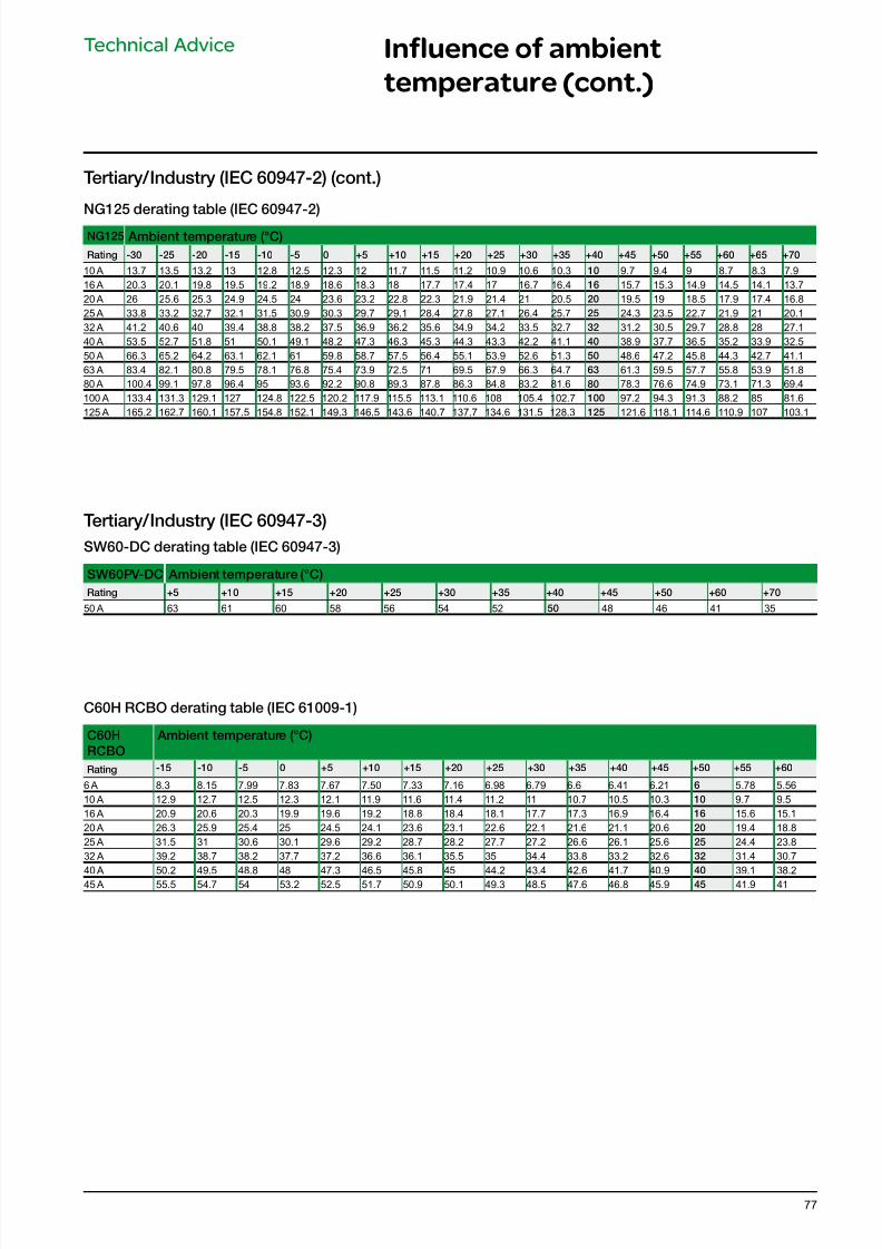
7/16/2019 Acti9 Launch Catalogue
http://slidepdf.com/reader/full/acti9-launch-catalogue 77/12477
C60H RCBO derating table (IEC 61009-1)
C60H
RCBO
Ambient temperature (°C)
Rating -15 -10 -5 0 +5 +10 +15 +20 +25 +30 +35 +40 +45 +50 +55 +60
6 A 8.3 8.15 7.99 7.83 7.67 7.50 7.33 7.16 6.98 6.79 6.6 6.41 6.21 6 5.78 5.5610 A 12.9 12.7 12.5 12.3 12.1 11.9 11.6 11.4 11.2 11 10.7 10.5 10.3 10 9.7 9.516 A 20.9 20.6 20.3 19.9 19.6 19.2 18.8 18.4 18.1 17.7 17.3 16.9 16.4 16 15.6 15.120 A 26.3 25.9 25.4 25 24.5 24.1 23.6 23.1 22.6 22.1 21.6 21.1 20.6 20 19.4 18.825 A 31.5 31 30.6 30.1 29.6 29.2 28.7 28.2 27.7 27.2 26.6 26.1 25.6 25 24.4 23.832 A 39.2 38.7 38.2 37.7 37.2 36.6 36.1 35.5 35 34.4 33.8 33.2 32.6 32 31.4 30.7
40 A 50.2 49.5 48.8 48 47.3 46.5 45.8 45 44.2 43.4 42.6 41.7 40.9 40 39.1 38.245 A 55.5 54.7 54 53.2 52.5 51.7 50.9 50.1 49.3 48.5 47.6 46.8 45.9 45 41.9 41
Technical Advice Influence of ambient
temperature (cont.)
Tertiary/Industry (IEC 60947-3)
SW60-DC derating table (IEC 60947-3)
SW60PV-DC Ambient temperature (°C)
Rating +5 +10 +15 +20 +25 +30 +35 +40 +45 +50 +60 +70
50 A 63 61 60 58 56 54 52 50 48 46 41 35
NG125 derating table (IEC 60947-2)
NG125 Ambient temperature (°C)
Rating -30 -25 -20 -15 -10 -5 0 +5 +10 +15 +20 +25 +30 +35 +40 +45 +50 +55 +60 +65 +70
10 A 13.7 13.5 13.2 13 12.8 12.5 12.3 12 11.7 11.5 11.2 10.9 10.6 10.3 10 9.7 9.4 9 8.7 8.3 7.916 A 20.3 20.1 19.8 19.5 19.2 18.9 18.6 18.3 18 17.7 17.4 17 16.7 16.4 16 15.7 15.3 14.9 14.5 14.1 13.720 A 26 25.6 25.3 24.9 24.5 24 23.6 23.2 22.8 22.3 21.9 21.4 21 20.5 20 19.5 19 18.5 17.9 17.4 16.825 A 33.8 33.2 32.7 32.1 31.5 30.9 30.3 29.7 29.1 28.4 27.8 27.1 26.4 25.7 25 24.3 23.5 22.7 21.9 21 20.132 A 41.2 40.6 40 39.4 38.8 38.2 37.5 36.9 36.2 35.6 34.9 34.2 33.5 32.7 32 31.2 30.5 29.7 28.8 28 27.140 A 53.5 52.7 51.8 51 50.1 49.1 48.2 47.3 46.3 45.3 44.3 43.3 42.2 41.1 40 38.9 37.7 36.5 35.2 33.9 32.550 A 66.3 65.2 64.2 63.1 62.1 61 59.8 58.7 57.5 56.4 55.1 53.9 52.6 51.3 50 48.6 47.2 45.8 44.3 42.7 41.163 A 83.4 82.1 80.8 79.5 78.1 76.8 75.4 73.9 72.5 71 69.5 67.9 66.3 64.7 63 61.3 59.5 57.7 55.8 53.9 51.880 A 100.4 99.1 97.8 96.4 95 93.6 92.2 90.8 89.3 87.8 86.3 84.8 83.2 81.6 80 78.3 76.6 74.9 73.1 71.3 69.4100 A 133.4 131.3 129.1 127 124.8 122.5 120.2 117.9 115.5 113.1 110.6 108 105.4 102.7 100 97.2 94.3 91.3 88.2 85 81.6125 A 165.2 162.7 160.1 157.5 154.8 152.1 149.3 146.5 143.6 140.7 137.7 134.6 131.5 128.3 125 121.6 118.1 114.6 110.9 107 103.1
Tertiary/Industry (IEC 60947-2) (cont.)
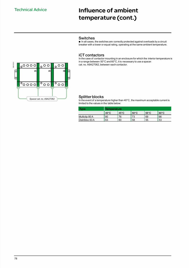
7/16/2019 Acti9 Launch Catalogue
http://slidepdf.com/reader/full/acti9-launch-catalogue 78/12478
D B 1 2 3 3 3 1
Spacer cat. no. A9A27062
Switches b In all cases, the switches are correctly protected against overloads by a circuit
breaker with a lower or equal rating, operating at the same ambient temperature.
iCT contactorsIn the case of contactor mounting in an enclosure for which the interior temperature isin a range between 50°C and 60°C, it is necessary to use a spacer,cat. no. A9A27062, between each contactor.
Splitter blocksIn the event of a temperature higher than 40°C, the maximum acceptable current islimited to the values in the table below:
Type Temperature
40°C 45°C 50°C 55°C 60°C
Multiclip 80 A 80 76 73 69 66Distribloc 63 A 63 60 58 55 53
Technical Advice Influence of ambient
temperature (cont.)
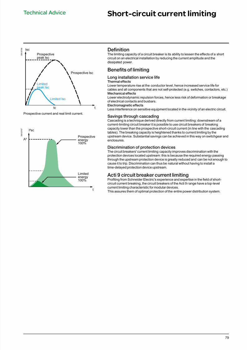
7/16/2019 Acti9 Launch Catalogue
http://slidepdf.com/reader/full/acti9-launch-catalogue 79/12479
D B 1 2 5 7 6 8
D B 1 2 5 7 6 7
Technical Advice Short-circuit current limiting
DenitionThe limiting capacity of a circuit breaker is its ability to lessen the effects of a shortcircuit on an electrical installation by reducing the current amplitude and the
dissipated power.
Benets o limiting
Long installation service lieThermal eects
Lower temperature rise at the conductor level, hence increased service life for cables and all components that are not self-protected (e.g. switches, contactors, etc.)Mechanical eects
Lower electrodynamic repulsion forces, hence less risk of deformation or breakageof electrical contacts and busbars.Electromagnetic eects
Less interference on sensitive equipment located in the vicinity of an electric circuit.
Savings through cascadingCascading is a technique derived directly from current limiting: downstream of acurrent-limiting circuit breaker it is possible to use circuit breakers of breakingcapacity lower than the prospective short-circuit current (in line with the cascadingtables). The breaking capacity is heightened thanks to current limiting by theupstream device. Substantial savings can be achieved in this way on switchgear andenclosures.
Discrimination o protection devicesThe circuit breakers' current limiting capacity improves discrimination with theprotection devices located upstream: this is because the required energy passingthrough the upstream protection device is greatly reduced and can be not enough tocause it to trip. Discrimination can thus be natural without having to install atime-delayed protection device upstream.
Acti 9 circuit breaker current limitingProting from Schneider Electric's experience and expertise in the eld of short-
circuit current breaking, the circuit breakers of the Acti 9 range have a top-levelcurrent limiting characteristic for modular devices.This assures them of optimal protection of the entire power distribution system.
I²sc
A²Prospectiveenergy100%
Limitedenergy100%
t
Isc
Prospectivepeak Isc
Limitedpeak Isc
Limited Isc
Prospective Isc
ttc
Prospective current and real limit current.
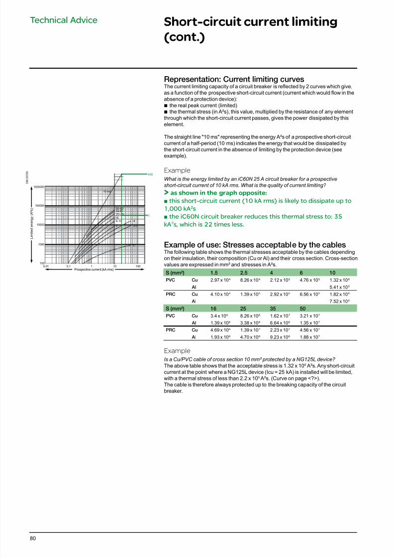
7/16/2019 Acti9 Launch Catalogue
http://slidepdf.com/reader/full/acti9-launch-catalogue 80/12480
D B 1 2 5 7 6 9
Technical Advice Short-circuit current limiting
(cont.)
Representation: Current limiting curvesThe current limiting capacity of a circuit breaker is reected by 2 curves which give,as a function of the prospective short-circuit current (current which would ow in the
absence of a protection device): b the real peak current (limited) b the thermal stress (in A²s), this value, multiplied by the resistance of any element
through which the short-circuit current passes, gives the power dissipated by thiselement.
The straight line "10 ms" representing the energy A²s of a prospective short-circuitcurrent of a half-period (10 ms) indicates the energy that would be dissipated bythe short-circuit current in the absence of limiting by the protection device (seeexample).
Example
What is the energy limited by an iC60N 25 A circuit breaker for a prospective
short-circuit current of 10 kA rms. What is the quality of current limiting?
> as shown in the graph opposite:b this short-circuit current (10 kA rms) is likely to dissipate up to
1,000 kA2s
b the iC60N circuit breaker reduces this thermal stress to: 35
kA2s, which is 22 times less.
Example o use: Stresses acceptable by the cablesThe following table shows the thermal stresses acceptable by the cables dependingon their insulation, their composition (Cu or Al) and their cross section. Cross-sectionvalues are expressed in mm² and stresses in A²s.
S (mm²) 1.5 2.5 4 6 10
PVC Cu 2.97 x 10⁴ 8.26 x 10⁴ 2.12 x 10⁵ 4.76 x 10⁵ 1.32 x 10⁶
Al 5.41 x 10⁵
PRC Cu 4.10 x 10⁴ 1.39 x 10⁵ 2.92 x 10⁵ 6.56 x 10⁵ 1.82 x 10⁶
Al 7.52 x 10⁵
S (mm²) 16 25 35 50
PVC Cu 3.4 x 10⁶ 8.26 x 10⁶ 1.62 x 10⁷ 3.21 x 10⁷
Al 1.39 x 10⁶ 3.38 x 10⁶ 6.64 x 10⁶ 1.35 x 10⁷
PRC Cu 4.69 x 10⁶ 1.39 x 10⁷ 2.23 x 10⁷ 4.56 x 10⁷
Al 1.93 x 10⁶ 4.70 x 10⁶ 9.23 x 10⁶ 1.88 x 10⁷
Example
Is a Cu/PVC cable of cross section 10 mm² protected by a NG125L device?
The above table shows that the acceptable stress is 1.32 x 10⁶ A²s. Any short-circuitcurrent at the point where a NG125L device (Icu = 25 kA) is installed will be limited,with a thermal stress of less than 2.2 x 10⁵ A²s. (Curve on page <?>).The cable is therefore always protected up to the breaking capacity of the circuit
breaker.
10000
100000
1000000
100
1000
1001010,10,01
≤1
4
6
8 -10
16
20 -25
32-4050 -63
2-3
10 ms
400
3
L i m i t e d e n e r g y ( A ² s )
Prospective current (kA rms)
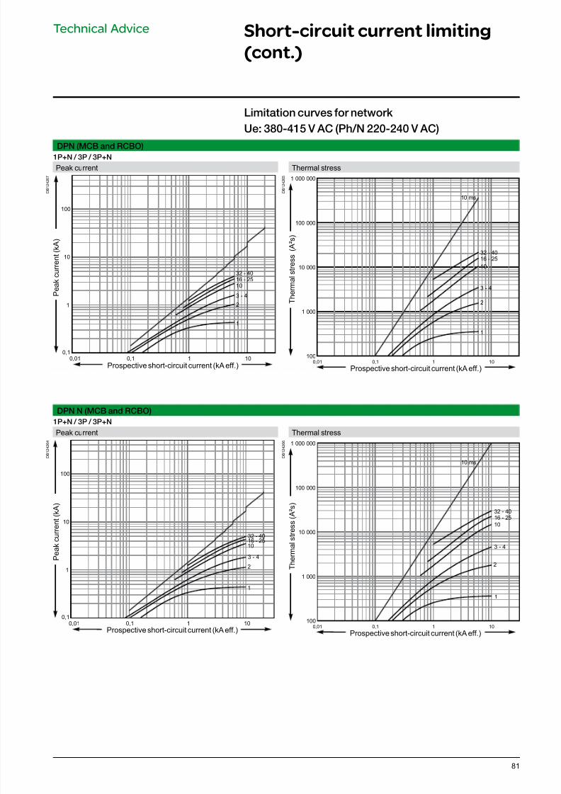
7/16/2019 Acti9 Launch Catalogue
http://slidepdf.com/reader/full/acti9-launch-catalogue 81/12481
DPN (MCB and RCBO)
1P+N / 3P / 3P+N
Peak current Thermal stress
D B 1 2 4 2 6 7
P e a k c u r r e n t ( k A )
Prospective short-circuit current (kA eff.)
0,1
1
10
100
1010,10,01
1
2
3 - 4
1016 - 25
32 - 40
D B 1 2 4 2 6 5
T h e r m a l
s t r e s s ( A ² s )
Prospective short-circuit current (kA eff.)
100
1 000
10 000
100 000
1 000 000
0,01 0,1 1 10
1
2
10
10 ms
3 - 4
16 - 25
32 - 40
DPN N (MCB and RCBO)
1P+N / 3P / 3P+N
Peak current Thermal stress
D B 1 2 4 2 6 4
0,1
1
10
100
1010,10,01
1
2
10
3 - 4
16 - 2532 - 40
P e a k c u r r e n t ( k A )
Prospective short-circuit current (kA eff.)
D B 1 2 4 2 6 6
100
1 000
10 000
100 000
1 000 000
0,01 0,1 1 10
1
2
10
10 ms
3 - 4
16 - 25
32 - 40
Prospective short-circuit current (kA eff.)
T h e r m a l s t r e s s ( A ² s )
Limitation curves or network
Ue: 380-415 V AC (Ph/N 220-240 V AC)
Technical Advice Short-circuit current limiting
(cont.)
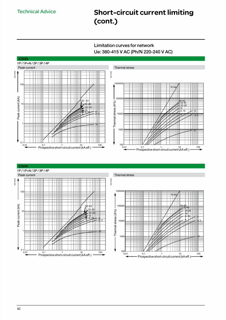
7/16/2019 Acti9 Launch Catalogue
http://slidepdf.com/reader/full/acti9-launch-catalogue 82/12482
Technical Advice Short-circuit current limiting
(cont.)
iC60N
1P / 1P+N / 2P / 3P / 4P
Peak current Thermal stress
D B 1 2 4 2 8 0
P e a k c u r r e n t ( k A )
Prospective short-circuit current (kA eff.)
0,1
1
10
100
1001010,10,01
y1
46
8 -10
16
20 -25
32 -40
50 - 63
2 - 3
D B 1 2 4 2 8 1
Prospective short-circuit current (kA eff.)
T h e r m a l s t r e
s s ( A ² s )
10000
100000
1000000
100
1000
1001010,10,01
y1
4
6
8-10
16
20 -25
32-4050 -63
2 -3
10 ms
iC60H1P / 1P+N / 2P / 3P / 4P
Peak current Thermal stress
D B 1 2 4 2 8 4
P e
a k c u r r e n t ( k A )
Prospective short-circuit current (kA eff.)
0,1
1
10
100
10 10010,10,01
y1
46
8 -10
16
20 -25
32 -40
50 -63
2 - 3
D B 1 2 4 2 8 5
Prospective short-circuit current (kA eff.)
T h e r m a l s
t r e s s ( A ² s )
10000
100000
1000000
100
1000
1001010,10,01
y1
4
6
8 -10
16
20-25
32-4050 -63
2-3
10 ms
Limitation curves or network
Ue: 380-415 V AC (Ph/N 220-240 V AC)
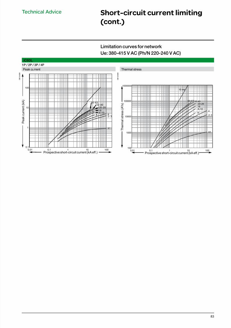
7/16/2019 Acti9 Launch Catalogue
http://slidepdf.com/reader/full/acti9-launch-catalogue 83/12483
Technical Advice Short-circuit current limiting
(cont.)
iC60L
1P / 2P / 3P / 4P
Peak current Thermal stress
D B 1 2 4 2 8 8
Prospective short-circuit current (kA eff.)
P e a k c u r r e n t ( k A )
0,1
1
10
100
1001010,10,01
y1
46
8 -10
16
20 -25
32 -40
50 -63
2 - 3
D B 1 2 4 2 8 9
Prospective short-circuit current (kA eff.)
T h e r m a l s t r e
s s ( A ² s )
10000
100000
1000000
100
1000
1001010,10,01
y1
46
8 -10
16
20-25
32-4050 -63
2 -3
10 ms
Limitation curves or network
Ue: 380-415 V AC (Ph/N 220-240 V AC)
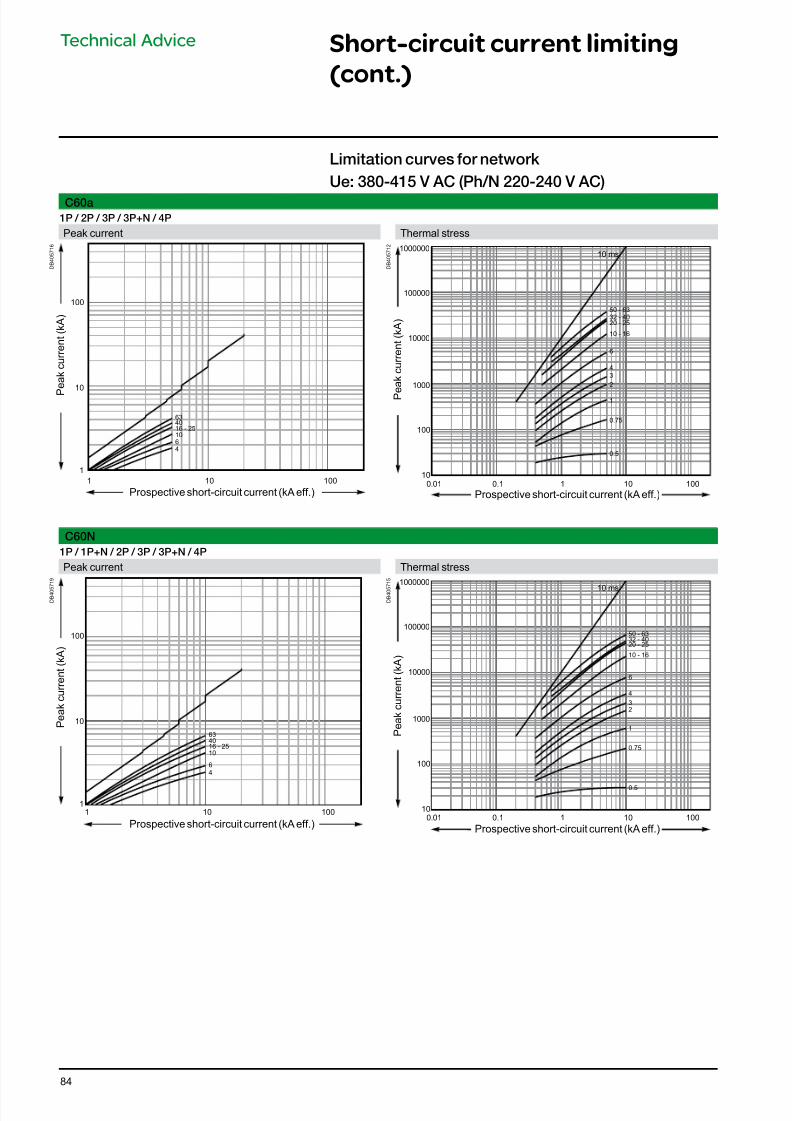
7/16/2019 Acti9 Launch Catalogue
http://slidepdf.com/reader/full/acti9-launch-catalogue 84/12484
Technical Advice Short-circuit current limiting
(cont.)
C60a
1P / 2P / 3P / 3P+N / 4P
Peak current Thermal stress
D B 4 0 5 7 1 6
100
10
1
100101
4
6
10
16 - 254063
D B 4 0 5 7 1 2
10000
100000
1000000
100
10
1000
1001010.10.01
10 ms
0.5
0.75
1
2
3
4
6
10 - 16
20 - 2532 - 40
50 - 63
C60N
1P / 1P+N / 2P / 3P / 3P+N / 4P
Peak current Thermal stress
D B 4 0 5
7 1 9
100
10
1
100101
4
6
10
16 - 2540
63
D B 4 0 5
7 1 5
10000
100000
1000000
100
10
1000
1001010.10.01
10 ms
0.5
0.75
1
2
3
4
6
10 - 16
20 - 2532 - 4050 - 63
Limitation curves or network
Ue: 380-415 V AC (Ph/N 220-240 V AC)
Prospective short-circuit current (kA eff.)
Prospective short-circuit current (kA eff.)
P e a k c u r r e n t ( k A )
P
e a k c u r r e n t ( k A )
Prospective short-circuit current (kA eff.)
Prospective short-circuit current (kA eff.)
P e a k c u r r e n t ( k A )
P e
a k c u r r e n t ( k A )
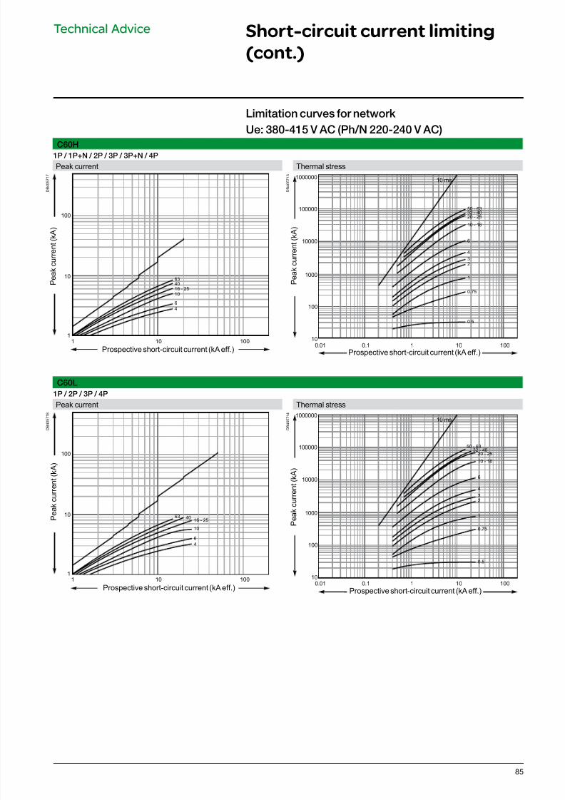
7/16/2019 Acti9 Launch Catalogue
http://slidepdf.com/reader/full/acti9-launch-catalogue 85/12485
C60H
1P / 1P+N / 2P / 3P / 3P+N / 4P
Peak current Thermal stress
D B 4 0 5 7 1 7
100
10
1
100101
4
6
10
16 - 25
4063
D B 4 0 5 7 1 3
10000
100000
1000000
100
10
1000
1001010.10.01
10 ms
0.5
0.75
1
2
3
4
6
10 - 16
20 - 2532 - 4050 - 63
C60L
1P / 2P / 3P / 4P
Peak current Thermal stress
D B 4 0 5
7 1 8
100
10
1
100101
4
6
10
16 - 254063
D B 4 0 5
7 1 4
10000
100000
1000000
100
10
1000
1001010.10.01
10 ms
0.5
0.75
1
2
3
4
6
10 - 16
20 - 2532 - 40
50 - 63
Limitation curves or network
Ue: 380-415 V AC (Ph/N 220-240 V AC)
Prospective short-circuit current (kA eff.)
Prospective short-circuit current (kA eff.)
P e a k c u r r e n t ( k A )
P e
a k c u r r e n t ( k A )
Prospective short-circuit current (kA eff.)
Prospective short-circuit current (kA eff.)
P e a k c u r r e n t ( k A )
P e a k c u r r e n t ( k A )
Technical Advice Short-circuit current limiting
(cont.)
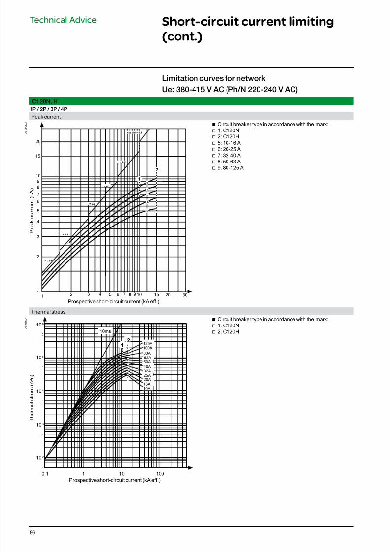
7/16/2019 Acti9 Launch Catalogue
http://slidepdf.com/reader/full/acti9-launch-catalogue 86/12486
C120N, H
1P / 2P / 3P / 4P
Peak current
D B 1 2 4 2 9 3
12 10
1
2
4
10
3
5
8
6
7
9
20
5 6 7 8 943 15 20
15
30
2
91
cos phi = 0.3
= 0.5
= 0.8
= 0.9
= 0.95
8
7
6
5
= 0.7
Prospective short-circuit current (kA eff.)
P e a k c u r r e n t ( k A
)
b Circuit breaker type in accordance with the mark: v 1: C120N v 2: C120H v 5: 10-16 A v 6: 20-25 A v 7: 32-40 A v 8: 50-63 A v 9: 80-125 A
Thermal stress
D B 4 0 5 6 0 4
10
10
10
10
10
6
5
2
4
3
0.1 1 10 100
5
5
5
5
5
2
1
16A
25A
32A
50A
125A
100A
63A
10A
20A
40A
80A
10ms
Prospective short-circuit current (kA eff.)
T h e r m a l s t r e s s ( A ² s )
b Circuit breaker type in accordance with the mark: v 1: C120N v 2: C120H
Limitation curves or network
Ue: 380-415 V AC (Ph/N 220-240 V AC)
Technical Advice Short-circuit current limiting
(cont.)
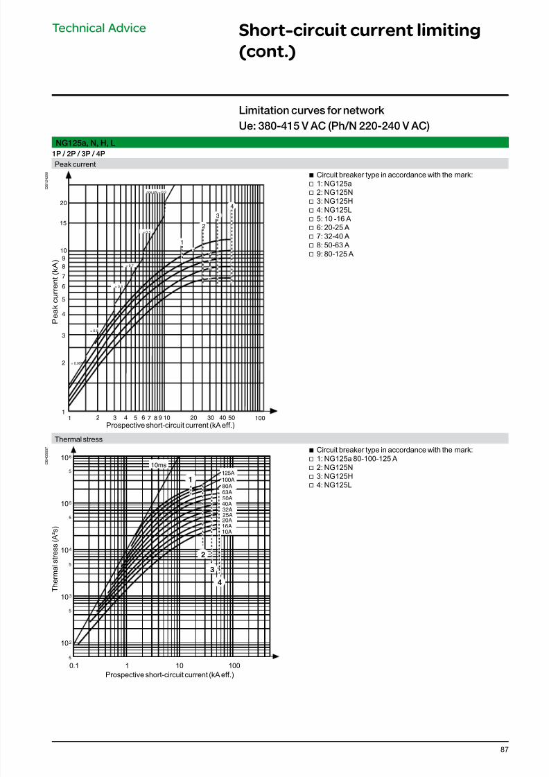
7/16/2019 Acti9 Launch Catalogue
http://slidepdf.com/reader/full/acti9-launch-catalogue 87/12487
NG125a, N, H, L
1P / 2P / 3P / 4P
Peak current
D B 1 2 4 2 9 9
Prospective short-circuit current (kA eff.)
P e a k c u r r e n t ( k
A )
1 2 101
2
4
10
3
5
8
6
7
9
20
5 6 7 8 943 10050403020
15
4
2
6
5
7
89
1
3
cos phi = 0.3
= 0.5
= 0.7
= 0.8
= 0.9
= 0.95
b Circuit breaker type in accordance with the mark: v 1: NG125a v 2: NG125N v 3: NG125H v 4: NG125L v 5: 10 -16 A v 6: 20-25 A v 7: 32-40 A v 8: 50-63 A v 9: 80-125 A
Thermal stress
D B 4 0 5 6 0 7
Prospective short-circuit current (kA eff.)
T h e r m a l s t r e s s
( A ² s )
10A
16A
20A
25A
32A
40A
50A
80A
125A
100A
63A
10ms
1
2
3
4
10
10
10
10
10
6
5
2
4
3
0.1 1 10 100
5
5
5
5
5
b Circuit breaker type in accordance with the mark: v 1: NG125a 80-100-125 A v 2: NG125N v 3: NG125H v 4: NG125L
Limitation curves or network
Ue: 380-415 V AC (Ph/N 220-240 V AC)
Technical Advice Short-circuit current limiting
(cont.)
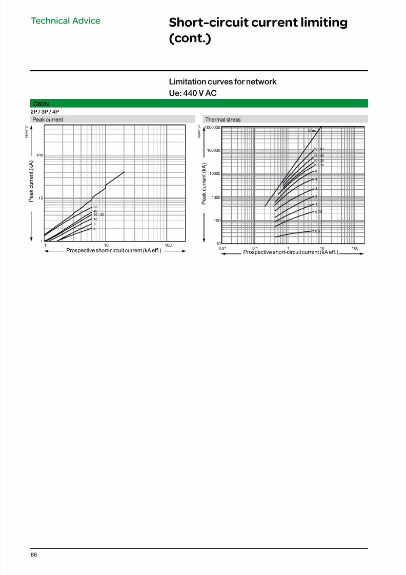
7/16/2019 Acti9 Launch Catalogue
http://slidepdf.com/reader/full/acti9-launch-catalogue 88/12488
C60N
2P / 3P / 4P
Peak current Thermal stress
D B 4 0 5 7 2 7
100
10
1100101
4
6
10
16 - 25
40
63
D B 4 0 5 7 2 3
10000
100000
1000000
100
10
1000
1001010.10.01
0.5
0.75
1
2
3
4
6
10 - 16
20 - 25
32 - 40
50 - 63
10 ms
Limitation curves or network
Ue: 440 V AC
Prospective short-circuit current (kA eff.)
P
e a k c u r r e n t ( k A )
Prospective short-circuit current (kA eff.)
P e a k c u r r e n t ( k A )
Technical Advice Short-circuit current limiting
(cont.)
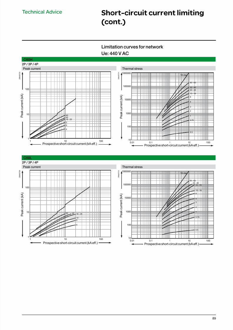
7/16/2019 Acti9 Launch Catalogue
http://slidepdf.com/reader/full/acti9-launch-catalogue 89/12489
C60H
2P / 3P / 4P
Peak current Thermal stress
D B 4 0 5 7 2 5
100
10
1
100101
4
6
0
16 - 25
4063
D B 4 0 5 7 2 1
10000
100000
1000000
100
10
1000
1001010.10.01
0.5
0.75
1
2
3
4
6
10 - 16
20 - 25
32 - 40
50 - 63
10 ms
C60L
2P / 3P / 4P
Peak current Thermal stress
D B 4 0 5
7 2 6
100
10
1100101
4
6
10
16 - 254063
D B 4 0 5
7 2 2
10000
100000
1000000
100
10
1000
1001010.10.01
0.5
0.75
1
2
3
4
6
10 - 16
20 - 25
32 - 40
50 - 63
10 ms
Limitation curves or network
Ue: 440 V AC
Prospective short-circuit current (kA eff.)
Prospective short-circuit current (kA eff.)
P e a k c u r r e n t ( k A )
P e
a k c u r r e n t ( k A )
Prospective short-circuit current (kA eff.)
Prospective short-circuit current (kA eff.)
P e a k c u r r e n t ( k A )
P e a k c u r r e n t ( k A )
Technical Advice Short-circuit current limiting
(cont.)
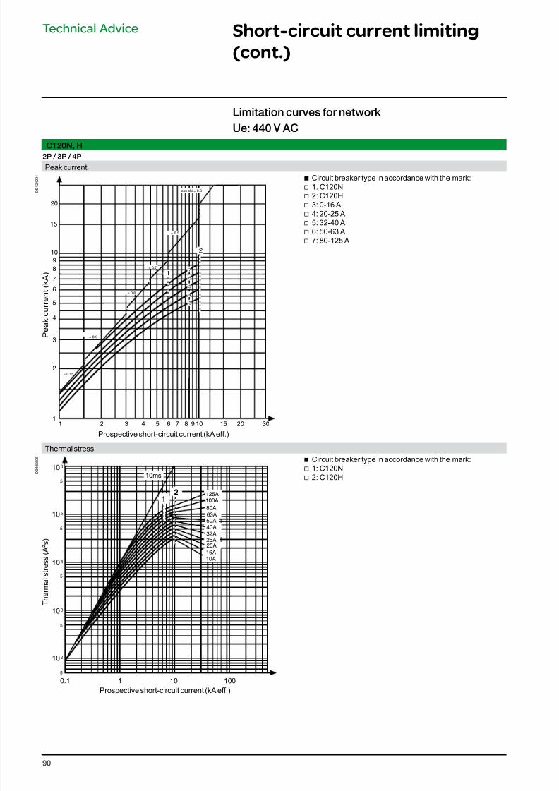
7/16/2019 Acti9 Launch Catalogue
http://slidepdf.com/reader/full/acti9-launch-catalogue 90/12490
C120N, H
2P / 3P / 4P
Peak current
D B 1 2 4 2 9 4
Prospective short-circuit current (kA eff.)
P e a k c u r r e n t ( k A
)
1 2 101
2
4
10
3
5
8
6
7
9
20
5 6 7 8 943 15 20
15
30
2
7
cos phi = 0.3
= 0.5
= 0.8
= 0.9
= 0.95
6
5
4
3
= 0.7
1
b Circuit breaker type in accordance with the mark: v 1: C120N v 2: C120H v 3: 0-16 A v 4: 20-25 A v 5: 32-40 A v 6: 50-63 A v 7: 80-125 A
Thermal stress
D B 4 0 5 6 0 5
Prospective short-circuit current (kA eff.)
T h e r m a l s t r e s s ( A ² s )
2
16A
25A
32A
50A
125A
100A
63A
10A
20A
40A
80A
1
10ms
10
10
10
10
10
6
5
2
4
3
0.1 1 10 100
5
5
5
5
5
b Circuit breaker type in accordance with the mark: v 1: C120N v 2: C120H
Limitation curves or network
Ue: 440 V AC
Technical Advice Short-circuit current limiting
(cont.)
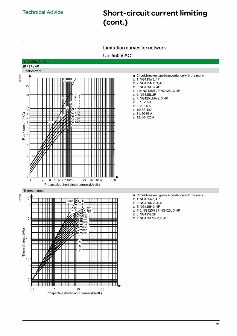
7/16/2019 Acti9 Launch Catalogue
http://slidepdf.com/reader/full/acti9-launch-catalogue 91/12491
NG125a, N, H, L
2P / 3P / 4P
Peak current
D B 1 2 4 3 0 0
Prospective short-circuit current (kA eff.)
P e a k c u r r e n t ( k A )
1 2 101
2
4
10
3
5
8
6
7
9
20
5 6 7 8 943 10050403020
15
2
9
8
101
3
cos phi = 0.3
= 0.5
= 0.7
= 0.8
= 0.9
= 0.95
6
4
11
12
57
b Circuit breaker type in accordance with the mark: v 1: NG125a 3, 4P v 2: NG125N 2, 3, 4P v 3: NG125H 3, 4P v 4-5: NG125H 2P/NG125L 3, 4P v 6: NG125L 2P v 7: NG125 LMA 2, 3, 4P v 8: 10 -16 A v 9: 20-25 A v 10: 32-40 A v 11: 50-63 A
v 12: 80-125 A
Thermal stress
D B 4 0 5 6 0 8
Prospective short-circuit current (kA eff.)
T h e r m a l s t r e s s ( A ² s )
10A
16A
20A
25A
32A
40A
50A
125A2
3 6
100A
63A
1
7
5
4
80A
10ms10
10
10
10
10
6
5
2
4
3
0.1 1 10 100
5
5
5
5
5
b Circuit breaker type in accordance with the mark: v 1: NG125a 3, 4P v 2: NG125N 2, 3, 4P v 3: NG125H 3, 4P v 4-5: NG125H 2P/NG125L 3, 4P v 6: NG125L 2P v 7: NG125LMA 2, 3, 4P
Limitation curves or network
Ue: 550 V AC
Technical Advice Short-circuit current limiting
(cont.)
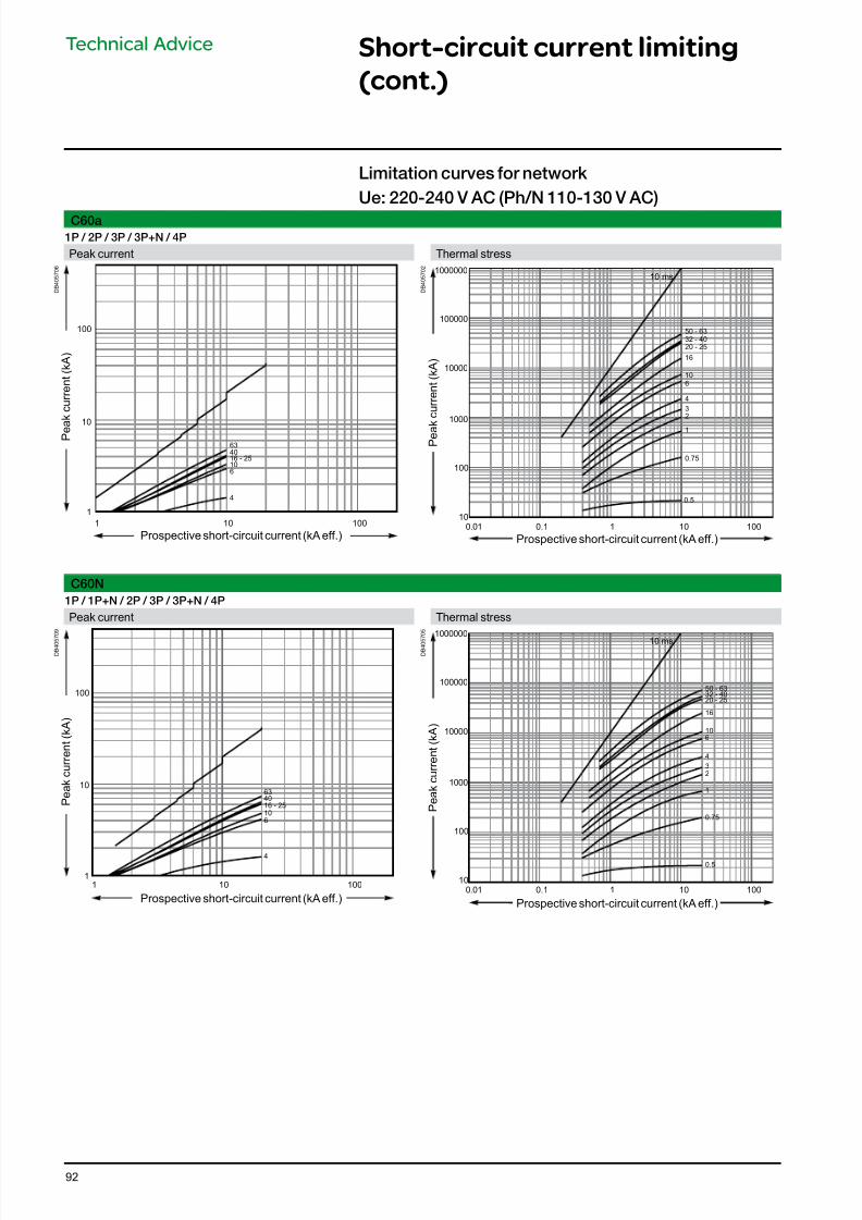
7/16/2019 Acti9 Launch Catalogue
http://slidepdf.com/reader/full/acti9-launch-catalogue 92/12492
C60a
1P / 2P / 3P / 3P+N / 4P
Peak current Thermal stress
D B 4 0 5 7 0 6
100
10
1
100101
4
6
1016 - 2540
63
D B 4 0 5 7 0 2
10 ms
0.5
0.75
1
2
3
4
6
10
16
20 - 25
32 - 40
50 - 63
10000
100000
1000000
100
10
1000
1001010.10.01
C60N
1P / 1P+N / 2P / 3P / 3P+N / 4P
Peak current Thermal stress
D B 4 0 5
7 0 9
100
10
1
100101
4
6
10
16 - 25
4063
D B 4 0 5
7 0 5
10000
100000
1000000
100
10
1000
1001010.10.01
10 ms
0.5
0.75
1
2
3
4
6
10
16
20 - 2532 - 4050 - 63
Limitation curves or network
Ue: 220-240 V AC (Ph/N 110-130 V AC)
Prospective short-circuit current (kA eff.)
Prospective short-circuit current (kA eff.)
P e a k c u r r e n t ( k A )
P e a
k c u r r e n t ( k A )
Prospective short-circuit current (kA eff.)
Prospective short-circuit current (kA eff.)
P e a k c u r r e n t ( k A )
P e a k c u r r e n t ( k A )
Technical Advice Short-circuit current limiting
(cont.)
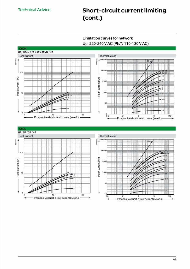
7/16/2019 Acti9 Launch Catalogue
http://slidepdf.com/reader/full/acti9-launch-catalogue 93/12493
C60H
1P / 1P+N / 2P / 3P / 3P+N / 4P
Peak current Thermal stress
D B 4 0 5 7 0 7
100
10
1
100101
04
6
10
16 - 2540
63
D B 4 0 5 7 0 3
10000
100000
1000000
100
10
1000
1001010.10.01
10 ms
0.5
0.75
1
2
3
4
6
10
16
20 - 2532 - 4050 - 63
C60L
1P / 2P / 3P / 4P
Peak current Thermal stress
D B 4 0 5
7 0 8
100
10
1
100101
4
6
10
1640
63
D B 4 0 5
7 0 4
10000
100000
1000000
100
10
1000
1001010.10.01
10 ms
0.5
0.75
01
2
3
4
6
10
16
20 - 2532 - 40
50 - 63
Technical Advice Short-circuit current limiting
(cont.)
Limitation curves or network
Ue: 220-240 V AC (Ph/N 110-130 V AC)
Prospective short-circuit current (kA eff.)
Prospective short-circuit current (kA eff.)
P e a k c u r r e n t ( k A )
P e
a k c u r r e n t ( k A )
Prospective short-circuit current (kA eff.)
Prospective short-circuit current (kA eff.)
P e a k c u r r e n t ( k A )
P e
a k c u r r e n t ( k A )
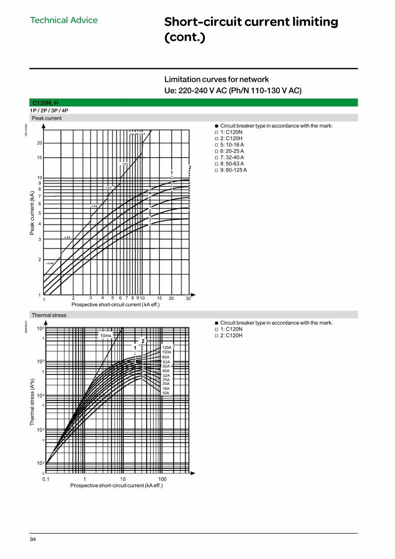
7/16/2019 Acti9 Launch Catalogue
http://slidepdf.com/reader/full/acti9-launch-catalogue 94/12494
Technical Advice Short-circuit current limiting
(cont.)
C120N, H
1P / 2P / 3P / 4P
Peak current
D B 1 2 4 2 9 2
Prospective short-circuit current (kA eff.)
P e a k c u r r e n t ( k A
)
12 10
1
2
4
10
3
5
8
6
7
9
20
5 6 7 8 943 15 20
15
30
2
9
1
cos phi = 0.3
= 0.5
= 0.8
= 0.9
= 0.95
8
7
6
5
= 0.7
b Circuit breaker type in accordance with the mark: v 1: C120N v 2: C120H v 5: 10-16 A v 6: 20-25 A v 7: 32-40 A v 8: 50-63 A v 9: 80-125 A
Thermal stress
D B 4 0 5 6 0 3
Prospective short-circuit current (kA eff.)
T h e r m a l s t r e s s
( A ² s )
2
10ms
1
16A
25A
32A
50A
125A
100A
63A
10A
20A
40A
80A
10
10
10
10
10
6
5
2
4
3
0.1 1 10 100
5
5
5
5
5
b Circuit breaker type in accordance with the mark: v 1: C120N v 2: C120H
Limitation curves or network
Ue: 220-240 V AC (Ph/N 110-130 V AC)
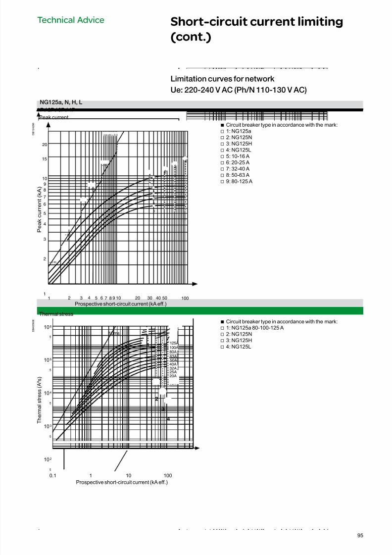
7/16/2019 Acti9 Launch Catalogue
http://slidepdf.com/reader/full/acti9-launch-catalogue 95/12495
Technical Advice Short-circuit current limiting
(cont.)
NG125a, N, H, L
1P / 2P / 3P / 4P
Peak current
D B 1 2 4 2 9 8
Prospective short-circuit current (kA eff.)
P e a k c u r r e n t ( k
A )
1 2 10
1
2
4
10
3
5
8
6
7
9
20
5 6 7 8 943 10050403020
154
3
2
6
5
7
8
9
1
cos phi = 0.3
= 0.5
= 0.7
= 0.8
= 0.9
= 0.95
b Circuit breaker type in accordance with the mark: v 1: NG125a v 2: NG125N v 3: NG125H v 4: NG125L v 5: 10-16 A v 6: 20-25 A v 7: 32-40 A v 8: 50-63 A v 9: 80-125 A
Thermal stress
D B 4 0 5 6 0 6
Prospective short-circuit current (kA eff.)
T h e r m a l s t r e s s ( A ² s )
1
2
3
4
10A
16A
40A
125A
100A
80A
63A
50A
32A
25A
20A
10ms
10
10
10
10
10
6
5
2
4
3
0.1 1 10 100
5
5
5
5
5
b Circuit breaker type in accordance with the mark: v 1: NG125a 80-100-125 A v 2: NG125N v 3: NG125H v 4: NG125L
Limitation curves or network
Ue: 220-240 V AC (Ph/N 110-130 V AC)
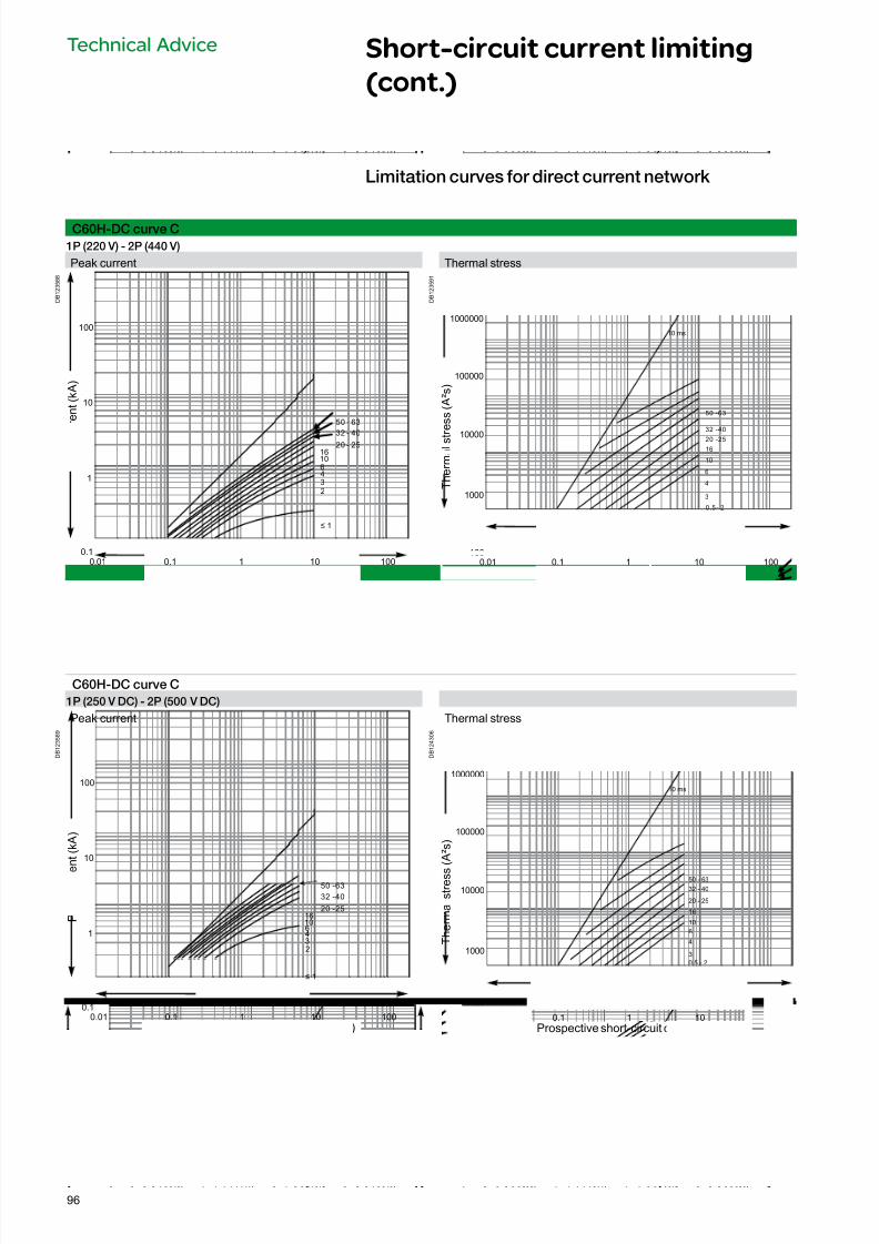
7/16/2019 Acti9 Launch Catalogue
http://slidepdf.com/reader/full/acti9-launch-catalogue 96/12496
Technical Advice Short-circuit current limiting
(cont.)
C60H-DC curve C
1P (220 V) - 2P (440 V)
Peak current Thermal stress
D B 1 2 3 5 8 8
0.1
1
10
100
1001010.10.01
≤ 1
2
3
46
1016
20 - 2532 - 40
50 - 63
Prospective short-circuit current (kA eff.)
P e a k c u
r r e n t ( k A )
D B 1 2 3 5 9 1
10000
100000
1000000
100
1000
1001010.10.01
0.5 - 2
3
4
6
10
16
20 -25
32 -40
50 -63
10 ms
Prospective short-circuit current (kA eff.)
T h e r m a l s t r e s s ( A ² s )
Limitation curves or direct current network
C60H-DC curve C
1P (250 V DC) - 2P (500 V DC)
Peak current Thermal stress
D B 1 2 3 5 8 9
0.1
1
10
100
1001010.10.01
≤ 1
2
3461016
20 -25
32 -40
50 -63
Prospective short-circuit current (kA eff.)
P e a k c u r r e
n t ( k A )
D B 1 2 4 3 0 6
10000
100000
1000000
100
1000
1001010.10.01
0.5 - 2
3
4
6
10
16
10 ms
50 - 63
32 - 40
20 - 25
Prospective short-circuit current (kA eff.)
T h e r m a l s t r e s s
( A ² s )
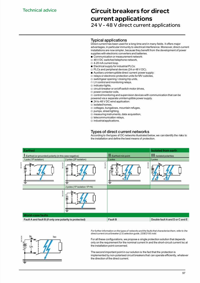
7/16/2019 Acti9 Launch Catalogue
http://slidepdf.com/reader/full/acti9-launch-catalogue 97/12497
Technical advice Circuit breakers for direct
current applications24 V - 48 V direct current applications
Typical applicationsDirect current has been used for a long time and in many elds. It offers major advantages, in particular immunity to electrical interference. Moreover, direct-current
installations are now simpler, because they benet from the development of power supplies with electronic converters and batteries.
b Communication or measurement network: v 48 V DC switched telephone network,
v 4-20 mA current loop.b Electrical supply for industrial PLCs:
v PLCs and peripheral devices (24 or 48 V DC).b Auxiliary uninterruptible direct current power supply:v relays or electronic protection units for MV cubicles,
v switchgear opening / closing trip units,v LV control and monitoring relays,
v indicator lights, v circuit-breaker or on/off switch motor drives, v power contactor coils, v control/monitoring and supervision devices with communication that can be
powered via a separate uninterruptible power supply.b 24 to 48 V DC wind application: v isolated homes, v cottages, bungalows, mountain refuges,
v pumps, street lighting, v measuring instruments, data acquisition, v telecommunication relays, v industrial applications.
Types o direct current networks According to the types of DC networks illustrated below, we can identify the risks tothe installation and dene the best means of protection.
For further information on the types of networks and the faults that characterise them, refer to thedirect current circuit breaker (LV) selection guide, 220E2100.indd.
For all these congurations, we propose a single protection solution that dependsonly on the requirement for the nominal current In and the short-circuit current Isc atthe installation point concerned.
The second important point in our solution is the fact that the protection isimplemented by non-polarised circuit breakers that can operate efciently, whatever the direction of the direct current.
D B 1 2 4 2 3 6
Earthed Isolated rom earth
I: Earthed (or grounded) polarity (in this case negative) II: Earthed mid-point III: Isolated polarities
1 pole (1P isolation) 2 poles (2P isolation) 2 poles 2 poles
D B 1 2 4 0 7 5
D B 1 2 4 0 6 7
D B 1 2 4 0 7 6
D B 1 2 4 0 6 8
D
E
2 poles (1P isolation 1P+N)
D B 1 2 4 3 8 7
Worst-case aults
Fault A and ault B (i only one polarity is protected) Fault B Double fault A and D or C and E
Isc
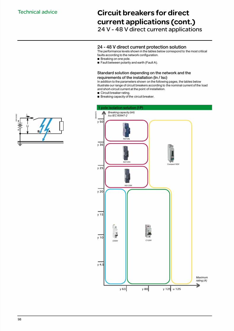
7/16/2019 Acti9 Launch Catalogue
http://slidepdf.com/reader/full/acti9-launch-catalogue 98/12498
Technical advice Circuit breakers for direct
current applications (cont.)24 V - 48 V direct current applications
D B 1 2 4 3 8 3
24 - 48 V direct current protection solutionThe performance levels shown in the tables below correspond to the most criticalfaults according to the network conguration.b Breaking on one pole.b Fault between polarity and earth (Fault A).
Standard solution depending on the network and the
requirements o the installation (In / Isc)In addition to the parameters shown on the following pages, the tables belowillustrate our range of circuit breakers according to the nominal current of the loadand short-circuit current at the point of installation.
b Circuit breaker rating. b Breaking capacity of the circuit breaker.
1 pole isolation solution (1P)
D B 4 0 5 5 7 5 Breaking capacity (kA)
Icu IEC 60947-2
Maximumrating (A)
y 10
y 15
y 20
y 25
y 36
y 63 y 80 y 125 u 125
y 50
C120H iC60H
NG125N
NG125H
NG125L
Compact NSX
y 4.5
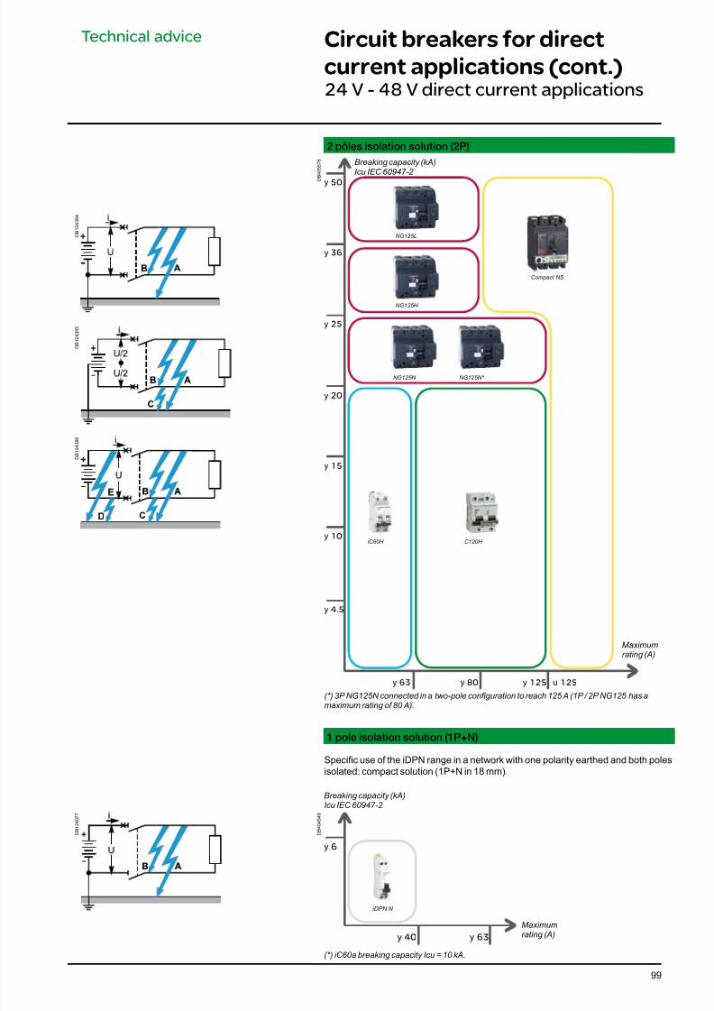
7/16/2019 Acti9 Launch Catalogue
http://slidepdf.com/reader/full/acti9-launch-catalogue 99/12499
Technical advice Circuit breakers for direct
current applications (cont.)24 V - 48 V direct current applications
(*) 3P NG125N connected in a two-pole conguration to reach 125 A (1P / 2P NG125 has a
maximum rating of 80 A).
1 pole isolation solution (1P+N)
Specic use of the iDPN range in a network with one polarity earthed and both polesisolated: compact solution (1P+N in 18 mm).
2 pôles isolation solution (2P)
D B
4 0 5 5 7 6
D B 1 2 4 3 8 4
D B 1 2 4 3 8 5
D B 1 2 4 3 8 6
Breaking capacity (kA)Icu IEC 60947-2
Maximumrating (A)
y 10
y 15
y 20
y 25
y 36
y 63 y 80 y 125 u 125
y 50
y 4.5
C120H iC60H
NG125N NG125N*
NG125H
NG125L
Compact NS
D
E
D B 4 0 4 5 4 9
D B 1 2 4 0 7 7
y 6
y 40 y 63
iDPN N
Breaking capacity (kA)Icu IEC 60947-2
Maximumrating (A)
(*) iC60a breaking capacity Icu = 10 kA.
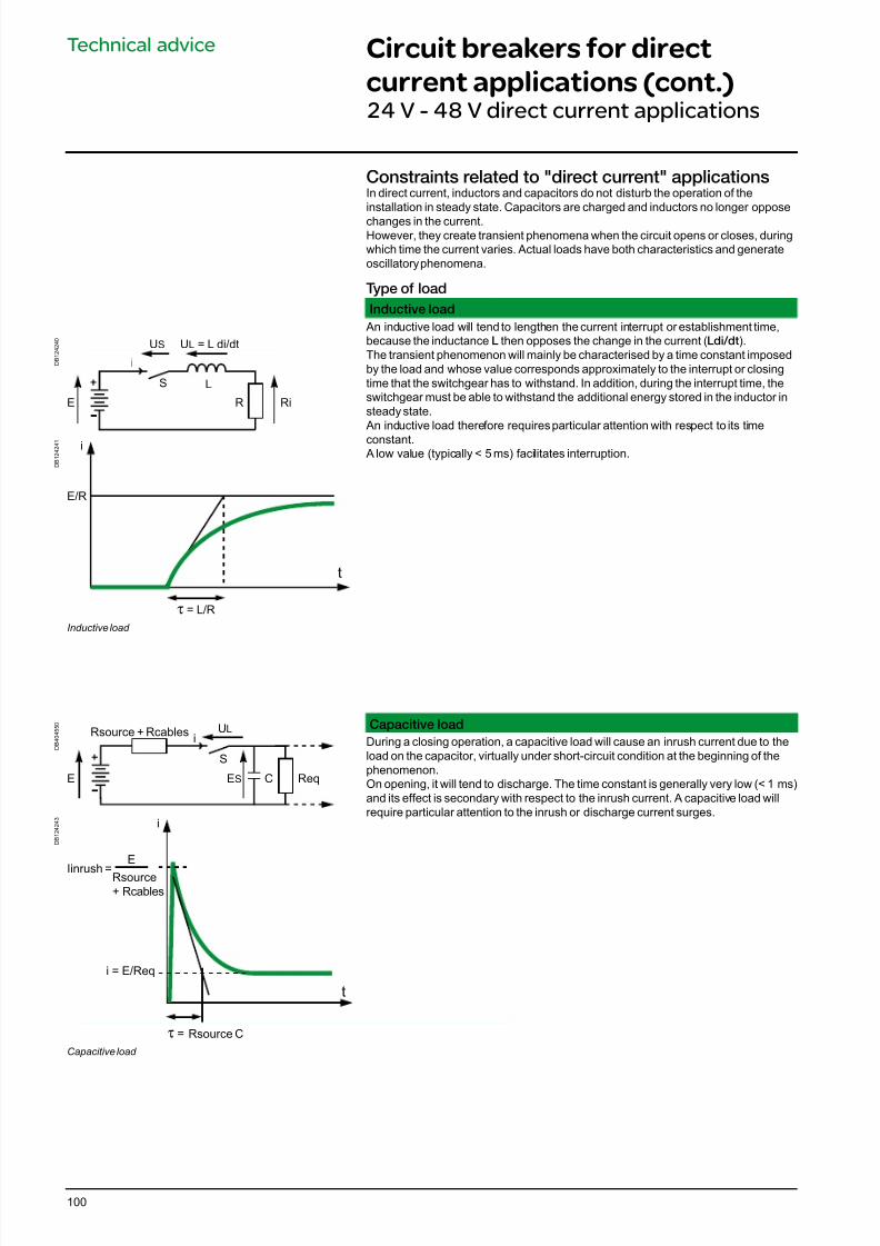
7/16/2019 Acti9 Launch Catalogue
http://slidepdf.com/reader/full/acti9-launch-catalogue 100/124100
Technical advice Circuit breakers for direct
current applications (cont.)24 V - 48 V direct current applications
Constraints related to "direct current" applicationsIn direct current, inductors and capacitors do not disturb the operation of theinstallation in steady state. Capacitors are charged and inductors no longer oppose
changes in the current.However, they create transient phenomena when the circuit opens or closes, duringwhich time the current varies. Actual loads have both characteristics and generateoscillatory phenomena.
Type o load
Inductive load
An inductive load will tend to lengthen the current interrupt or establishment time,because the inductance L then opposes the change in the current (Ldi/dt).The transient phenomenon will mainly be characterised by a time constant imposedby the load and whose value corresponds approximately to the interrupt or closingtime that the switchgear has to withstand. In addition, during the interrupt time, theswitchgear must be able to withstand the additional energy stored in the inductor insteady state. An inductive load therefore requires particular attention with respect to its time
constant. A low value (typically < 5 ms) facilitates interruption.
Capacitive load
During a closing operation, a capacitive load will cause an inrush current due to theload on the capacitor, virtually under short-circuit condition at the beginning of thephenomenon.On opening, it will tend to discharge. The time constant is generally very low (< 1 ms)and its effect is secondary with respect to the inrush current. A capacitive load willrequire particular attention to the inrush or discharge current surges.
D B 1 2 4 2 4 0
US
i
S L
RE Ri
UL = L di/dt
D B 1 2 4 2 4 1
E/R
τ = L/R
i
t
Inductive load
D B 4 0 4 5 5 0
i
S
CE ReqES
ULRsource + Rcables
D B 1 2 4 2 4 3
τ =
i
i = E/Req
E
t
Rsource+ Rcables
Iinrush =
Rsource C
Capacitive load
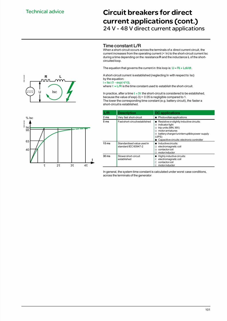
7/16/2019 Acti9 Launch Catalogue
http://slidepdf.com/reader/full/acti9-launch-catalogue 101/124101
Technical advice
Time constant L/RWhen a short-circuit occurs across the terminals of a direct current circuit, thecurrent increases from the operating current (< In) to the short-circuit current Isc
during a time depending on the resistance R and the inductance L of the short-circuited loop.
The equation that governs the current in this loop is: U = Ri + Ldi/dt.
A short-circuit current is established (neglecting In with respect to Isc)by the equation:i = Isc (1 - exp(-t/ τ )),where τ = L/R is the time constant used to establish the short-circuit.
In practice, after a time t = 3 τ the short-circuit is considered to be established,because the value of exp(-3) = 0.05 is negligible compared to 1.The lower the corresponding time constant (e.g. battery circuit), the faster ashort-circuit is established.
L/R Description DC applications2 ms Very fast short-circuit b Photovoltaic applications
5 ms Fast short-circuit established b Resistive or slightly inductive circuits:v indicator light
v trip units (MN, MX) v motor armatures
v battery charger/uninterruptible power supply(UPS)
b Capacitive circuits: electronic controller 15 ms Standardised value used in
standard IEC 60947-2b Inductive circuits:
v electromagnetic coil v contactor coil v motor inductor
30 ms Slower short-circuitestablished
b Highly inductive circuits: v electromagnetic coil v contactor coil v motor inductor
In general, the system time constant is calculated under worst case conditions,across the terminals of the generator.
Circuit breakers for direct
current applications (cont.)24 V - 48 V direct current applications
D B 1 2 4 2 4 5
D B 1 2 4 2 4 6
R L
Isc
95
63
40
τ
t
2τ 3τ 4τ
% Isc
Isc
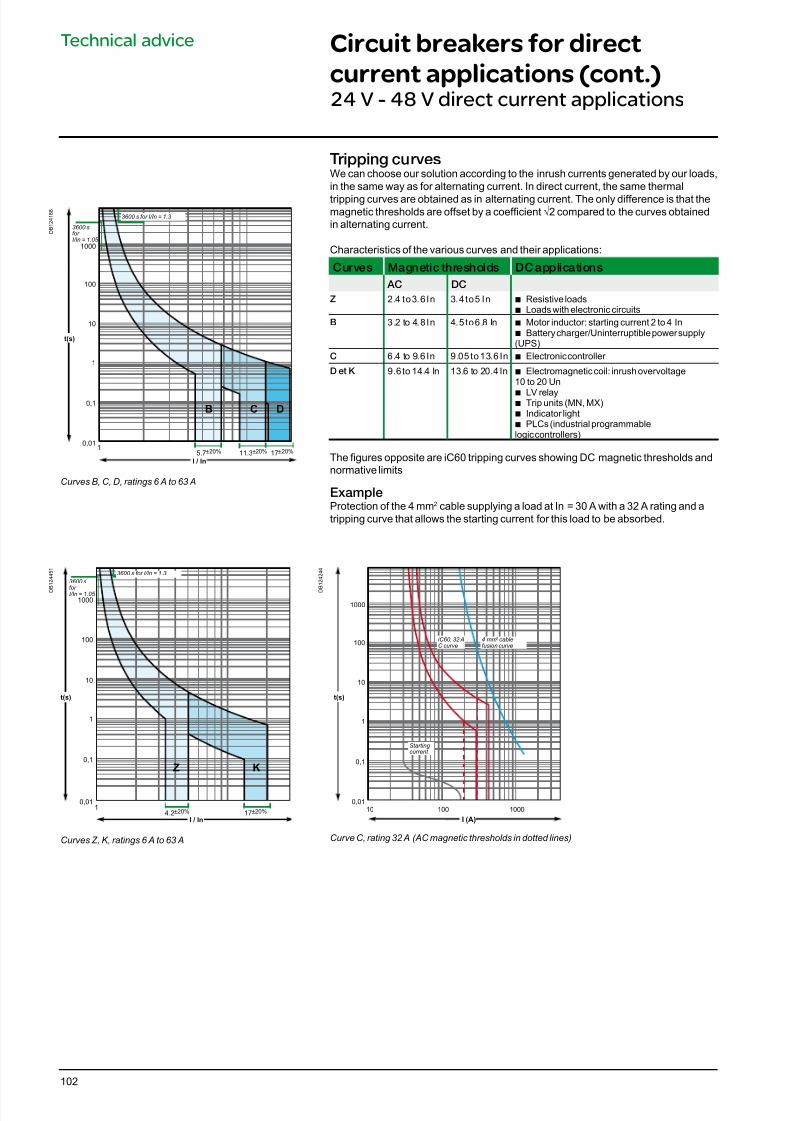
7/16/2019 Acti9 Launch Catalogue
http://slidepdf.com/reader/full/acti9-launch-catalogue 102/124102
Technical advice Circuit breakers for direct
current applications (cont.)24 V - 48 V direct current applications
Tripping curvesWe can choose our solution according to the inrush currents generated by our loads,in the same way as for alternating current. In direct current, the same thermal
tripping curves are obtained as in alternating current. The only difference is that themagnetic thresholds are offset by a coefcient √2 compared to the curves obtainedin alternating current.
Characteristics of the various curves and their applications:
Curves Magnetic thresholds DC applications
AC DC
Z 2.4 to 3.6 In 3.4 to 5 In b Resistive loads b Loads with electronic circuits
B 3.2 to 4.8 In 4.5 to 6.8 In b Motor inductor: starting current 2 to 4 Inb Battery charger/Uninterruptible power supply(UPS)
C 6.4 to 9.6 In 9.05 to 13.6 In b Electronic controller
D et K 9.6 to 14.4 In 13.6 to 20.4 In b Electromagnetic coil: inrush overvoltage10 to 20 Un
b LV relay b Trip units (MN, MX) b Indicator light b PLCs (industrial programmable
logic controllers)
The gures opposite are iC60 tripping curves showing DC magnetic thresholds andnormative limits
ExampleProtection of the 4 mm2 cable supplying a load at In = 30 A with a 32 A rating and atripping curve that allows the starting current for this load to be absorbed.
D B 1 2 4 1 8 8
t(s)
0,01
0,1
1
10
100
1000
I / In
B C D
15.7±20% 11.3±20% 17±20%
3600 s for I/In = 1.3
3600 sfor I/In = 1.05
Curves B, C, D, ratings 6 A to 63 A
D B
1 2 4 2 4 4
t(s)
0,01
0,1
1
10
100
1000
I (A)
100 100010
4 mm2 cablefusion curve
Starting current
iC60, 32 AC curve
Curve C, rating 32 A (AC magnetic thresholds in dotted lines)
D B
1 2 4 4 5 1
I / In
t(s)
0,01
0,1
1
10
100
1000
KZ
14.2±20% 17±20%
3600 s for I/In = 1.3
3600 s
for I/In = 1.05
Curves Z, K, ratings 6 A to 63 A
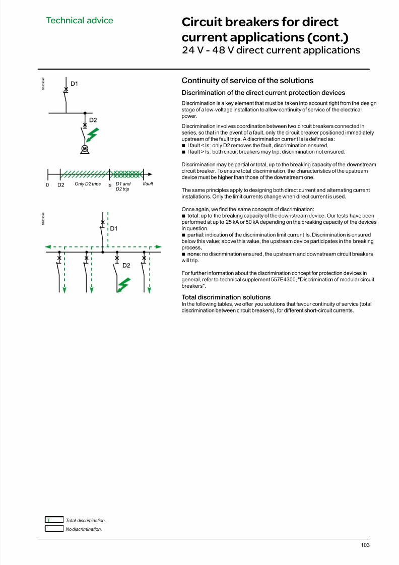
7/16/2019 Acti9 Launch Catalogue
http://slidepdf.com/reader/full/acti9-launch-catalogue 103/124
D B 1 2 4 2 4 8
103
Technical advice Circuit breakers for direct
current applications (cont.)24 V - 48 V direct current applications
T Total discrimination.
No discrimination.
Continuity o service o the solutions
Discrimination o the direct current protection devices
Discrimination is a key element that must be taken into account right from the designstage of a low-voltage installation to allow continuity of service of the electricalpower.
Discrimination involves coordination between two circuit breakers connected inseries, so that in the event of a fault, only the circuit breaker positioned immediatelyupstream of the fault trips. A discrimination current Is is dened as:b I fault < Is: only D2 removes the fault, discrimination ensured,b I fault > Is: both circuit breakers may trip, discrimination not ensured.
Discrimination may be partial or total, up to the breaking capacity of the downstreamcircuit breaker. To ensure total discrimination, the characteristics of the upstreamdevice must be higher than those of the downstream one.
The same principles apply to designing both direct current and alternating current
installations. Only the limit currents change when direct current is used.
Once again, we nd the same concepts of discrimination: b total: up to the breaking capacity of the downstream device. Our tests have been
performed at up to 25 kA or 50 kA depending on the breaking capacity of the devicesin question.
b partial: indication of the discrimination limit current Is. Discrimination is ensuredbelow this value; above this value, the upstream device participates in the breakingprocess,b none: no discrimination ensured, the upstream and downstream circuit breakerswill trip.
For further information about the discrimination concept for protection devices ingeneral, refer to technical supplement 557E4300, "Discrimination of modular circuitbreakers".
Total discrimination solutionsIn the following tables, we offer you solutions that favour continuity of service (totaldiscrimination between circuit breakers), for different short-circuit currents.
D B 1 2 4 2 4 7
Only D2 trips D1 and D2 trip
Ifault 0 D2 Is
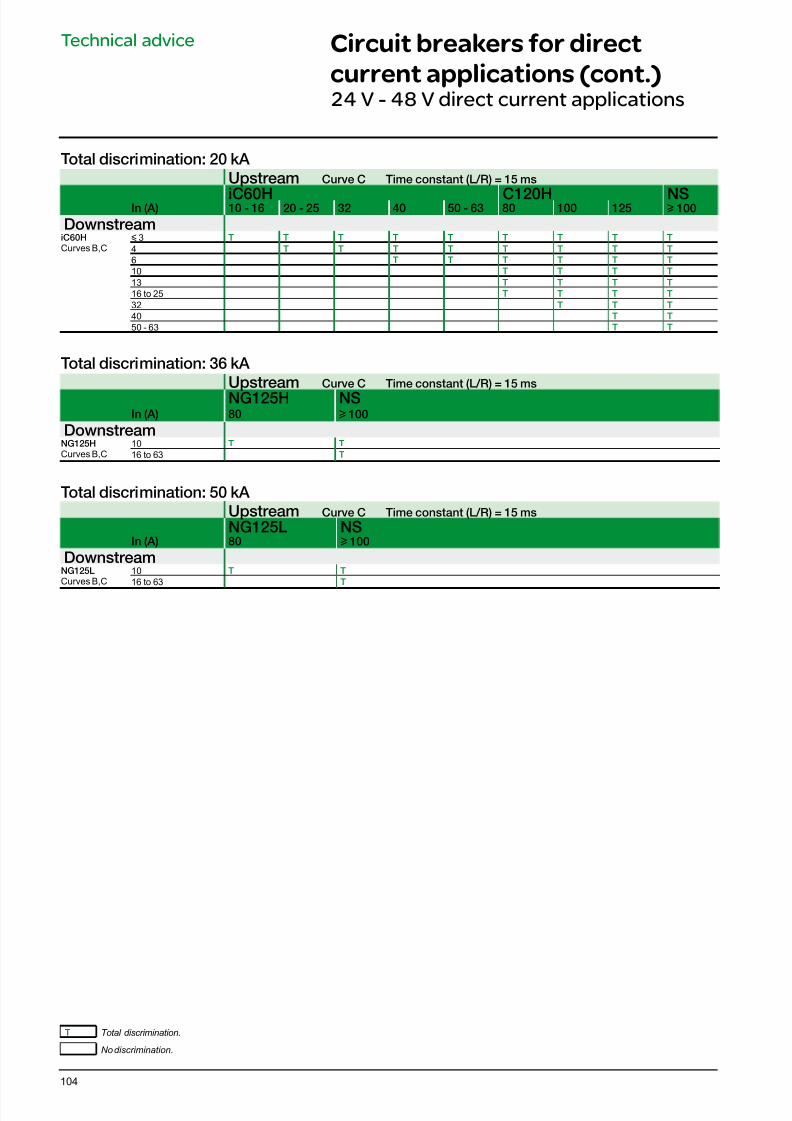
7/16/2019 Acti9 Launch Catalogue
http://slidepdf.com/reader/full/acti9-launch-catalogue 104/124104
Technical advice Circuit breakers for direct
current applications (cont.)24 V - 48 V direct current applications
Total discrimination: 20 kA
Upstream Curve C Time constant (L/R) = 15 ms
iC60H C120H NSIn (A) 10 - 16 20 - 25 32 40 50 - 63 80 100 125 u 100
DownstreamiC60HCurves B,C
y 3 T T T T T T T T T
4 T T T T T T T T
6 T T T T T T
10 T T T T
13 T T T T
16 to 25 T T T T
32 T T T
40 T T
50 - 63 T T
Total discrimination: 36 kA
Upstream Curve C Time constant (L/R) = 15 ms
NG125H NSIn (A) 80 u 100
DownstreamNG125HCurves B,C
10 T T
16 to 63 T
Total discrimination: 50 kA
Upstream Curve C Time constant (L/R) = 15 ms
NG125L NSIn (A) 80 u 100
DownstreamNG125LCurves B,C
10 T T
16 to 63 T
T Total discrimination.
No discrimination.
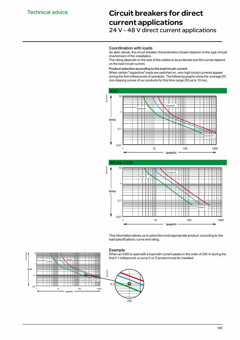
7/16/2019 Acti9 Launch Catalogue
http://slidepdf.com/reader/full/acti9-launch-catalogue 105/124105
Technical advice Circuit breakers for direct
current applications24 V - 48 V direct current applications
D B 1 2 4 2 5 1
D B 1 2 4 2 4 9
Coordination with loads As seen above, the circuit-breaker characteristics chosen depend on the type of loaddownstream of the installation.
The rating depends on the size of the cables to be protected and the curves dependon the load inrush current.
Product selection according to the load inrush current
When certain "capacitive" loads are switched on, very high inrush currents appear during the rst milliseconds of operation. The following graphs show the average DCnon-tripping curves of our products for this time range (50 μs to 10 ms).
iC60
D B 1 2 4 2 4 9
Ipeak/In
t(ms)
0,01
0,1
1
10
100 1000101
Curve D
Curve B
Curve C
NG125 / C120
D B 1 2 4 2 5 0
t(ms)
0,01
0,1
1
10
100 1000101
Ipeak/In
Curve D
Curve B
Curve C
This information allows us to select the most appropriate product, according to theload specications: curve and rating.
ExampleWhen an iC60 is used with a load with current peaks in the order of 200 In during therst 0.1 millisecond, a curve C or D product must be installed.
Ipeak/In
t(ms)
0,01
0,1
1
10
100 1000101
Curve D
Curve B
Curve C
0,1
200
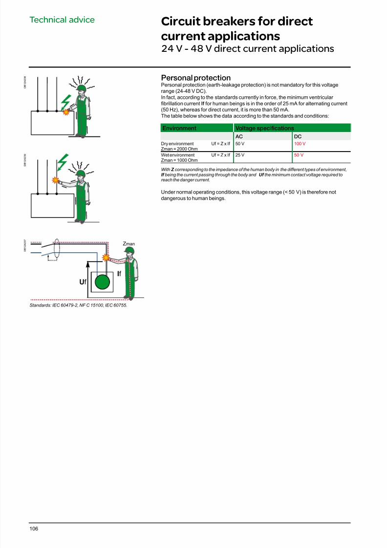
7/16/2019 Acti9 Launch Catalogue
http://slidepdf.com/reader/full/acti9-launch-catalogue 106/124106
Technical advice Circuit breakers for direct
current applications24 V - 48 V direct current applications
Personal protectionPersonal protection (earth-leakage protection) is not mandatory for this voltagerange (24-48 V DC).
In fact, according to the standards currently in force, the minimum ventricular brillation current I for human beings is in the order of 25 mA for alternating current(50 Hz), whereas for direct current, it is more than 50 mA.The table below shows the data according to the standards and conditions:
Environment Voltage specications
AC DC
Dry environmentZman = 2000 Ohm
Uf = Z x If 50 V 100 V
Wet environmentZman = 1000 Ohm
Uf = Z x If 25 V 50 V
With Z corresponding to the impedance of the human body in the different types of environment,If being the current passing through the body and Uf the minimum contact voltage required toreach the danger current.
Under normal operating conditions, this voltage range (< 50 V) is therefore notdangerous to human beings.
D B 1 2 4 2 3 8
D B 1 2 4 2 3 9
D B 1 2 4 2 3 7
Uf
If
Zman
Standards: IEC 60479-2, NF C 15100, IEC 60755.
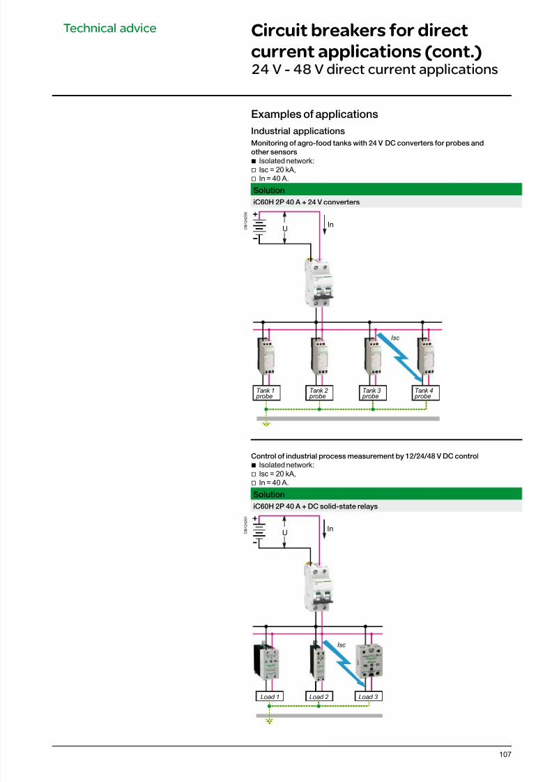
7/16/2019 Acti9 Launch Catalogue
http://slidepdf.com/reader/full/acti9-launch-catalogue 107/124107
Technical advice Circuit breakers for direct
current applications (cont.)24 V - 48 V direct current applications
Examples o applications
Industrial applications
Monitoring o agro-ood tanks with 24 V DC converters or probes and
other sensors
b Isolated network: v Isc = 20 kA, v In = 40 A.
Solution
iC60H 2P 40 A + 24 V converters
D B 1 2 4 2 5 8
InU
Tank 1 probe
Tank 2 probe
Tank 3 probe
Tank 4 probe
Isc
Control o industrial process measurement by 12/24/48 V DC control
b Isolated network: v Isc = 20 kA, v In = 40 A.
Solution
iC60H 2P 40 A + DC solid-state relays
D B 1 2 4 2 6 1
InU
Isc
Load 1 Load 2 Load 3
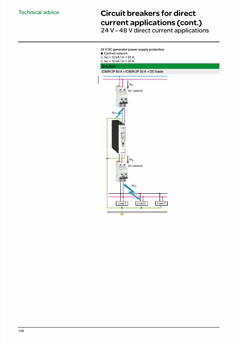
7/16/2019 Acti9 Launch Catalogue
http://slidepdf.com/reader/full/acti9-launch-catalogue 108/124108
Technical advice Circuit breakers for direct
current applications (cont.)24 V - 48 V direct current applications
24 V DC generator power supply protection
b Earthed network:v Isc = 10 kA / In = 63 A,
v Isc = 10 kA / In = 20 A.
Solution
iC60H 2P 63 A + iC60N 2P 20 A + DC loads
D B 1 2 4 2 6 2
In1
In2
Isc 1
AC network
Load 1
Isc 2
DC network
Load 2 Load 3
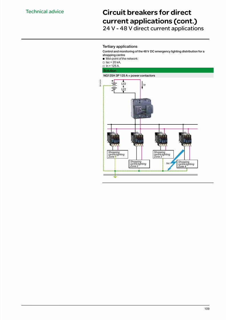
7/16/2019 Acti9 Launch Catalogue
http://slidepdf.com/reader/full/acti9-launch-catalogue 109/124109
Technical advice Circuit breakers for direct
current applications (cont.)24 V - 48 V direct current applications
Tertiary applications
Control and monitoring o the 48 V DC emergency lighting distribution or a
shopping centreb Mid-point of the network:
v Isc = 20 kA, v In = 125 A.
Solution
NG125H 3P 125 A + power contactors
D B 1 2 4 2 5 9
U/2
U/2
In
Isc
Shopping centre lighting Zone 1
Shopping centre lighting Zone 2
Shopping centre lighting Zone 3
Shopping centre lighting Zone 4
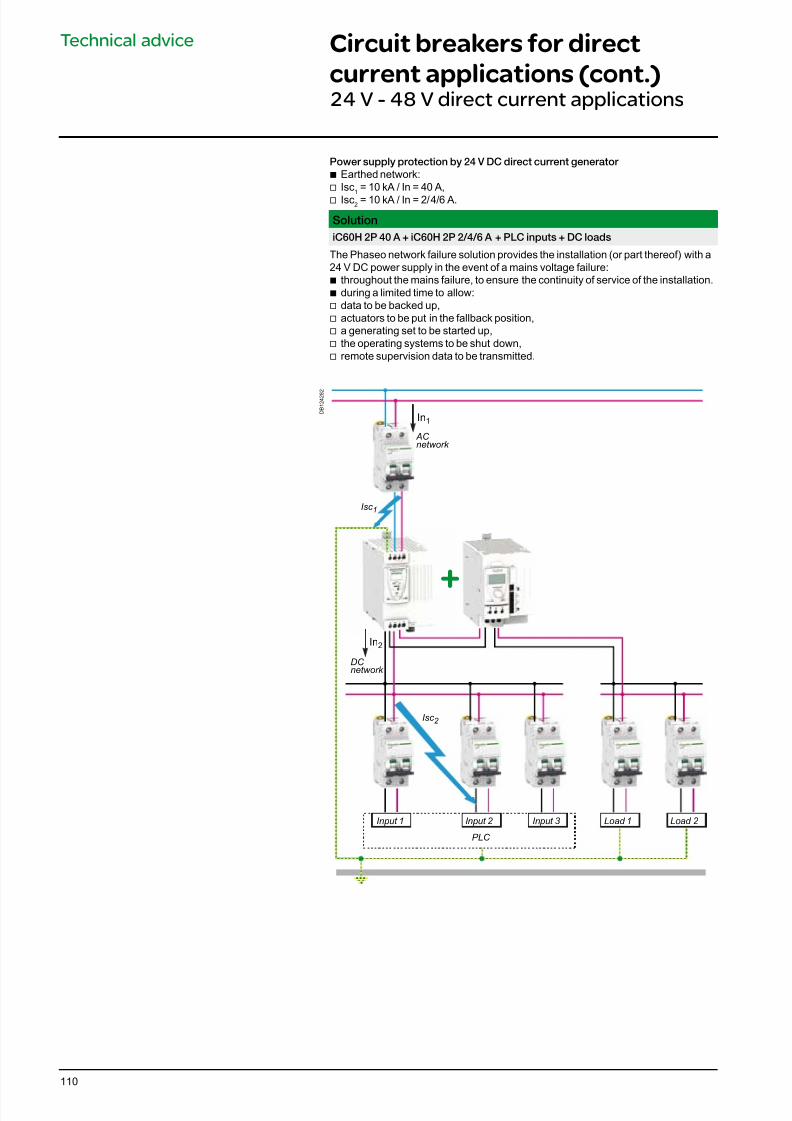
7/16/2019 Acti9 Launch Catalogue
http://slidepdf.com/reader/full/acti9-launch-catalogue 110/124110
Technical advice Circuit breakers for direct
current applications (cont.)24 V - 48 V direct current applications
Power supply protection by 24 V DC direct current generator
b Earthed network:v Isc
1= 10 kA / In = 40 A,
v Isc2 = 10 kA / In = 2/4/6 A.
Solution
iC60H 2P 40 A + iC60H 2P 2/4/6 A + PLC inputs + DC loads
The Phaseo network failure solution provides the installation (or part thereof) with a24 V DC power supply in the event of a mains voltage failure:b throughout the mains failure, to ensure the continuity of service of the installation.
b during a limited time to allow: v data to be backed up, v actuators to be put in the fallback position, v a generating set to be started up,
v the operating systems to be shut down, v remote supervision data to be transmitted.
D B 1 2 4 2 8 2
In1
In2
+
AC network
DC network
Load 1Input 1 Input 2
PLC
Input 3 Load 2
Isc 1
Isc 2
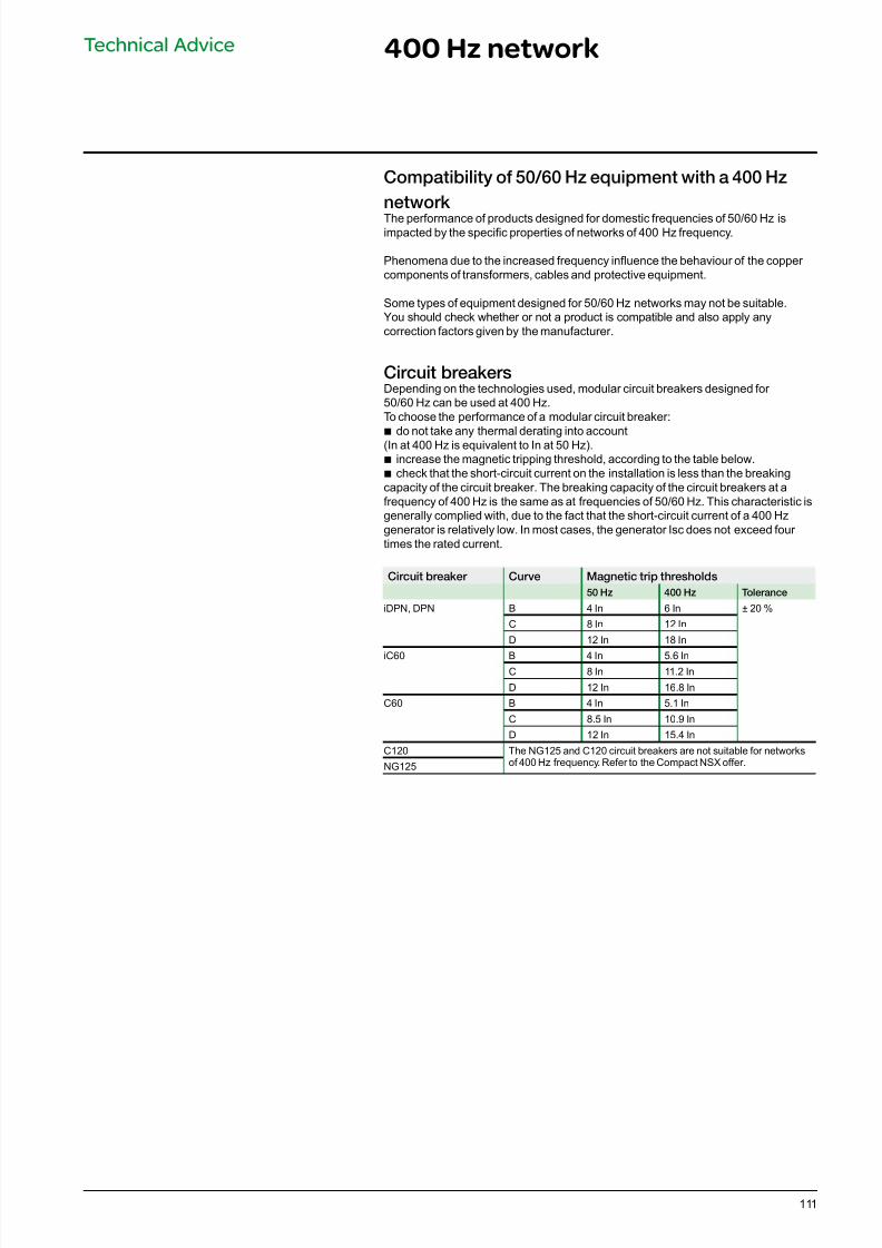
7/16/2019 Acti9 Launch Catalogue
http://slidepdf.com/reader/full/acti9-launch-catalogue 111/124111
Technical Advice 400 Hz network
Compatibility o 50/60 Hz equipment with a 400 Hz
network The performance of products designed for domestic frequencies of 50/60 Hz isimpacted by the specic properties of networks of 400 Hz frequency.
Phenomena due to the increased frequency inuence the behaviour of the copper components of transformers, cables and protective equipment.
Some types of equipment designed for 50/60 Hz networks may not be suitable.You should check whether or not a product is compatible and also apply anycorrection factors given by the manufacturer.
Circuit breakersDepending on the technologies used, modular circuit breakers designed for 50/60 Hz can be used at 400 Hz.To choose the performance of a modular circuit breaker:
b
do not take any thermal derating into account(In at 400 Hz is equivalent to In at 50 Hz). b increase the magnetic tripping threshold, according to the table below. b check that the short-circuit current on the installation is less than the breaking
capacity of the circuit breaker. The breaking capacity of the circuit breakers at afrequency of 400 Hz is the same as at frequencies of 50/60 Hz. This characteristic isgenerally complied with, due to the fact that the short-circuit current of a 400 Hzgenerator is relatively low. In most cases, the generator Isc does not exceed four times the rated current.
Circuit breaker Curve Magnetic trip thresholds
50 Hz 400 Hz Tolerance
iDPN, DPN B 4 In 6 In ± 20 %
C 8 In 12 In
D 12 In 18 In
iC60 B 4 In 5.6 InC 8 In 11.2 In
D 12 In 16.8 In
C60 B 4 In 5.1 In
C 8.5 In 10.9 In
D 12 In 15.4 In
C120 The NG125 and C120 circuit breakers are not suitable for networksof 400 Hz frequency. Refer to the Compact NSX offer.NG125
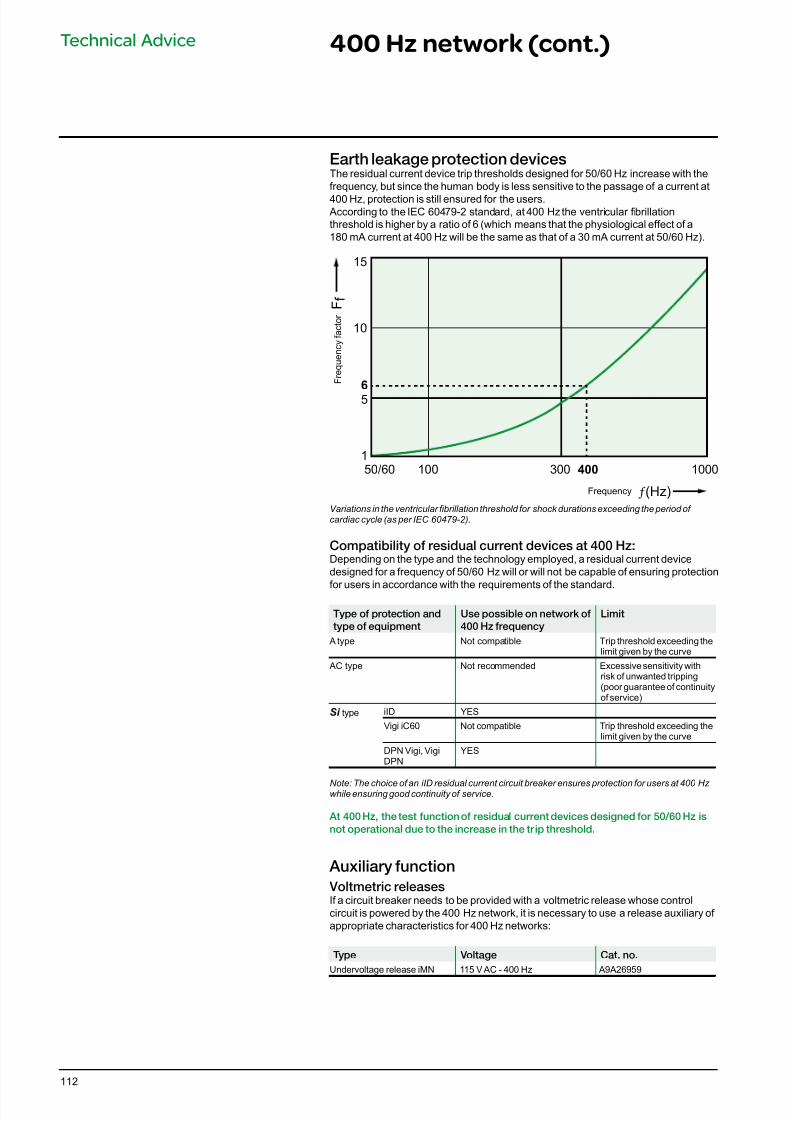
7/16/2019 Acti9 Launch Catalogue
http://slidepdf.com/reader/full/acti9-launch-catalogue 112/124112
Technical Advice 400 Hz network (cont.)
Compatibility o residual current devices at 400 Hz:Depending on the type and the technology employed, a residual current devicedesigned for a frequency of 50/60 Hz will or will not be capable of ensuring protection
for users in accordance with the requirements of the standard.
Type o protection and
type o equipment
Use possible on network o
400 Hz requency
Limit
A type Not compatible Trip threshold exceeding thelimit given by the curve
AC type Not recommended Excessive sensitivity withrisk of unwanted tripping(poor guarantee of continuityof service)
Si type iID YES
Vigi iC60 Not compatible Trip threshold exceeding thelimit given by the curve
DPN Vigi, VigiDPN
YES
Note: The choice of an iID residual current circuit breaker ensures protection for users at 400 Hz while ensuring good continuity of service.
At 400 Hz, the test unction o residual current devices designed or 50/60 Hz is
not operational due to the increase in the tr ip threshold.
Auxiliary unction
Voltmetric releasesIf a circuit breaker needs to be provided with a voltmetric release whose controlcircuit is powered by the 400 Hz network, it is necessary to use a release auxiliary of appropriate characteristics for 400 Hz networks:
Type Voltage Cat. no.
Undervoltage release iMN 115 V AC - 400 Hz A9A26959
15
F f
50/60 100 300
ƒ (Hz)
1000
10
56
1400
F r e q u e n c y f a c t o r
Frequency
Variations in the ventricular brillation threshold for shock durations exceeding the period of cardiac cycle (as per IEC 60479-2).
Earth leakage protection devicesThe residual current device trip thresholds designed for 50/60 Hz increase with thefrequency, but since the human body is less sensitive to the passage of a current at
400 Hz, protection is still ensured for the users. According to the IEC 60479-2 standard, at 400 Hz the ventricular brillationthreshold is higher by a ratio of 6 (which means that the physiological effect of a180 mA current at 400 Hz will be the same as that of a 30 mA current at 50/60 Hz).

7/16/2019 Acti9 Launch Catalogue
http://slidepdf.com/reader/full/acti9-launch-catalogue 113/124113
Dimensions
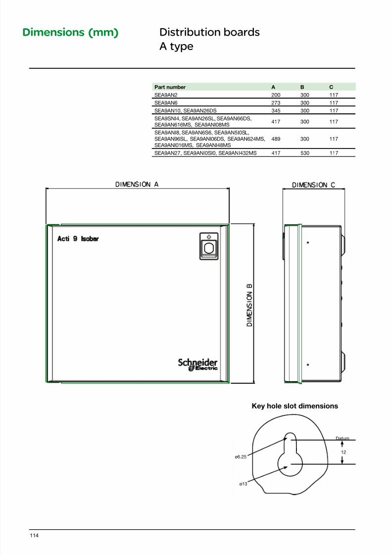
7/16/2019 Acti9 Launch Catalogue
http://slidepdf.com/reader/full/acti9-launch-catalogue 114/124114
Dimensions (mm)
Part number A B C
SEA9AN2 200 300 117SEA9AN6 273 300 117
SEA9AN10, SEA9AN26DS 345 300 117
SEA9SNI4, SEA9AN26SL, SEA9AN66DS,SEA9AN616MS, SEA9ANI08MS
417 300 117
SEA9ANI8, SEA9AN6S6, SEA9AN5I0SL,
SEA9AN96SL, SEA9ANI06DS, SEA9AN624MS,
SEA9ANI016MS, SEA9ANI48MS
489 300 117
SEA9AN27, SEA9ANI0SI0, SEA9ANI432MS 417 530 117
Datum
12ø6.25
ø13
Key hole slot dimensions
Distribution boards
A type
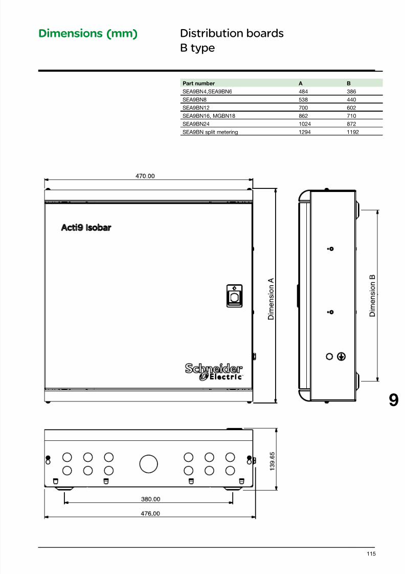
7/16/2019 Acti9 Launch Catalogue
http://slidepdf.com/reader/full/acti9-launch-catalogue 115/124115
9
Dimensions (mm)
™
Part number A B
SEA9BN4,SEA9BN6 484 386
SEA9BN8 538 440SEA9BN12 700 602
SEA9BN16, MGBN18 862 710
SEA9BN24 1024 872
SEA9BN split metering 1294 1192
Distribution boards
B type
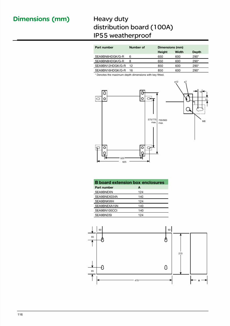
7/16/2019 Acti9 Launch Catalogue
http://slidepdf.com/reader/full/acti9-launch-catalogue 116/124116
Dimensions (mm)
Part number Number of Dimensions (mm)
Height Width Depth
SEA9BN6HDGK/G-R 6 650 600 290*SEA9BN8HDGK/G-R 8 650 600 290*
SEA9BN12HDGK/G-R 12 850 600 290*
SEA9BN16HDGK/G-R 16 850 600 290*
* Denotes the maximum depth dimensions with key itted.
525
625
575/775
max.700/900
max.M8
ø12 ø7
10
10
B board extension box enclosuresPart number A
SEA9BNEXN 124
SEA9BNEX034N 140
SEA9BNKWH 124
SEA9BNEXA15N 140
SEA9BN100CCI 140
SEA9BNDSI 124
270
470 A
6060
65
65
Heavy duty
distribution board (100A)
IP55 weatherproof

7/16/2019 Acti9 Launch Catalogue
http://slidepdf.com/reader/full/acti9-launch-catalogue 117/124117
Weight (g)
Circuit-breaker
Type iC60H
1P 125
2P 250
3P 375
4P 500
iC60H circuit breakersProtection
Circuit protection
Dimensions (mm)
D B 4 0 5 5 8 4 72
54
3650
5.5
85
4.6
64
69.5
78.5
18
4P
3P
2P
1P
45
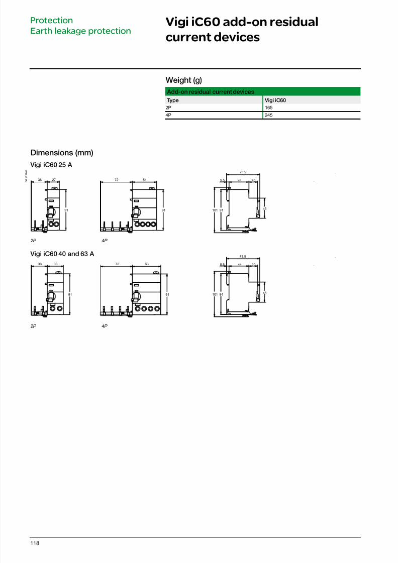
7/16/2019 Acti9 Launch Catalogue
http://slidepdf.com/reader/full/acti9-launch-catalogue 118/124118
Vigi iC60 add-on residual
current devices
Protection
Earth leakage protection
Dimensions (mm)
Vigi iC60 25 A
D B 1 2 2 7 6 6
2P 4P
Vigi iC60 40 and 63 A
2P 4P
91
91
36 27
36 36
.
.
.
.
9145
91
91
101
72 63
72 54
73.5
445.5 20
91
45
101
73.5
445.5 20
Weight (g)
Add-on residual current devices
Type Vigi iC60
2P 165
4P 245
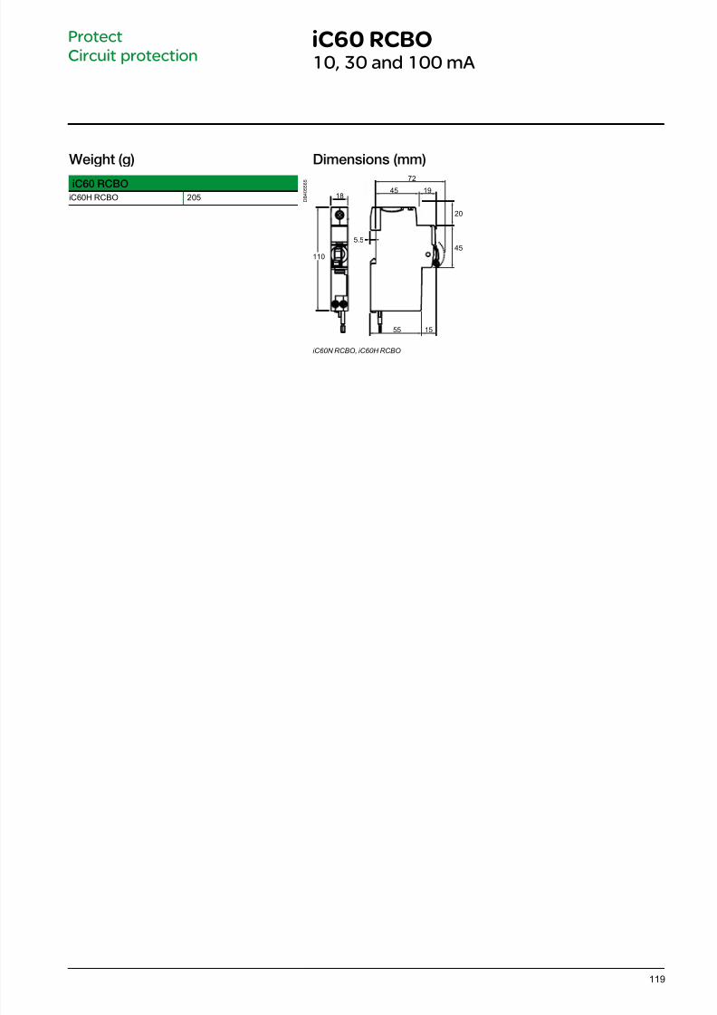
7/16/2019 Acti9 Launch Catalogue
http://slidepdf.com/reader/full/acti9-launch-catalogue 119/124119
iC60 RCBO10, 30 and 100 mA
Protect
Circuit protection
Dimensions (mm)
D B 4 0 5 5 6 5
110
1845 19
72
20
45
55 15
5.5
iC60N RCBO, iC60H RCBO
Weight (g)
iC60 RCBO
iC60H RCBO 205
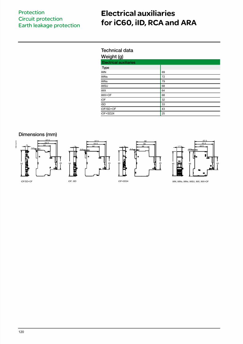
7/16/2019 Acti9 Launch Catalogue
http://slidepdf.com/reader/full/acti9-launch-catalogue 120/124120
Dimensions (mm)
D B 1 2 4 2 2 3
iOF/SD+OF iOF, iSD iOF+SD24 iMN, iMNs, iMNx, iMSU, iMX, iMX+OF
90
9
67.5
63.5
44
5.5
86
9
45
67.5
63.5
44
5.5
45
67.5
63.5
49.5
5.5
4545 8685
17.59
68
66
44
5.5
88
Technical data
Weight (g)Electrical auxiliaries
Type
iMN 69
iMNs 72
iMNx 79
iMSU 68
iMX 64
iMX+OF 68
iOF 32
iSD 33
iOF/SD+OF 43
iOF+SD24 25
Electrical auxiliaries
for iC60, iID, RCA and ARA
Protection
Circuit protection
Earth leakage protection
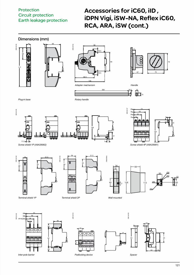
7/16/2019 Acti9 Launch Catalogue
http://slidepdf.com/reader/full/acti9-launch-catalogue 121/124121
Accessories for iC60, iID ,
iDPN Vigi, iSW-NA, Reflex iC60,
RCA, ARA, iSW (cont.)
Protection
Circuit protection
Earth leakage protection
Dimensions (mm)
D B 1
2 4 1 4 9 19 655
177
54
D B 1
2 4 1 5 2
88.5
96
360 18.5 10
10
85
18.5
135
75
18.547
17
75
Handle Adapter mechanism
Plug-in base Rotary handle
D B 1 2 4 1 4 8 72
54
36
6 36
20
81
20
4P
3P
1P+N/2P D B 1 2 4 1 4 3
16
27
17
D B 1 2 4 1 5 0
44 18
9 5
15
4585
Inter-pole barrier Padlocking device Spacer
D B 1 2 4 1 4 4
18 51.5
3549
D B 1 2 4 1 4 5 36 51.5
3549
D B 4 0 5 9 6 4
34
18
457
30
10
Ø8
Ø4
Ø8
Ø4
40128 113
56
Terminal shield 1P Terminal shield 2P Wall mounted
D B 1 2 4 1 4 6
11.5
11
31
9
106
D B 1 2 4 1 4 7
72
54
36
18
4P
3P
2P
1P
1125
106
9
Screw shield 1P (A9A26982) Screw shield 4P (A9A26981)
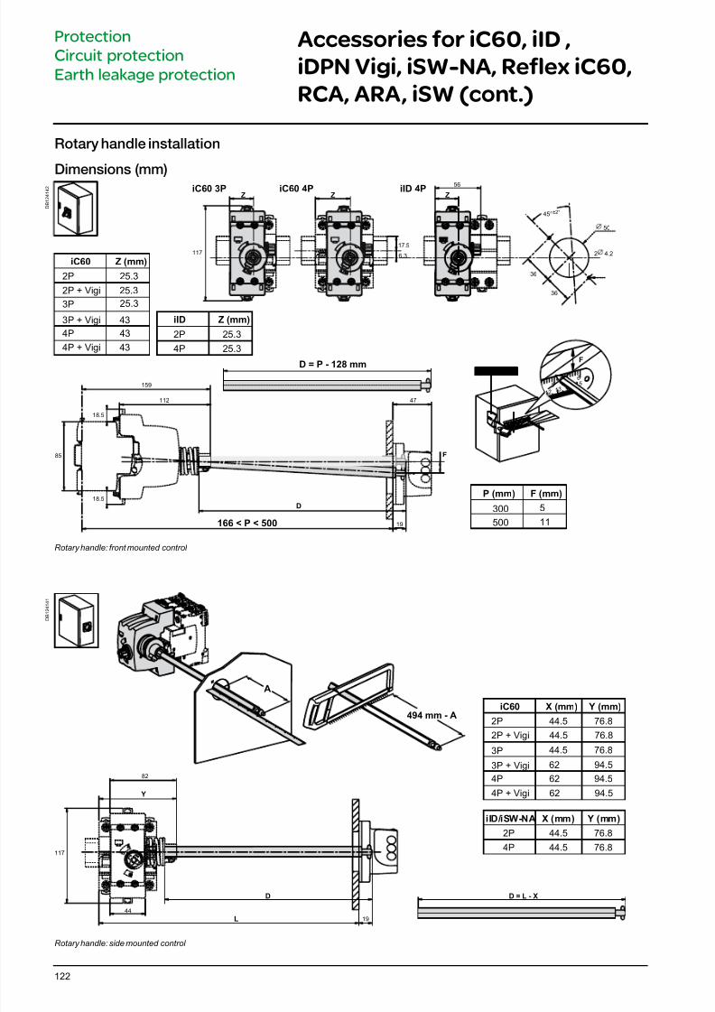
7/16/2019 Acti9 Launch Catalogue
http://slidepdf.com/reader/full/acti9-launch-catalogue 122/124122
Accessories for iC60, iID ,
iDPN Vigi, iSW-NA, Reflex iC60,
RCA, ARA, iSW (cont.)
Protection
Circuit protection
Earth leakage protection
Rotary handle installation
Dimensions (mm)
D B 1 2 4 1 4 2
iC60 Z (mm)
2P 25.3
3P 25.3
4P 43
4P + Vigi 43
3P + Vigi 43
2P + Vigi 25.3
iID Z (mm)
2P 25.3
4P 25.3
D = P - 128 mm
P (mm) F (mm)
300 5
500 11166 < P < 500
D
F
159
19
F
5
1213
156
GVAPL01
Z ZZ
6.3
17.5
2
36
36
4.2
50
45°±2°
iC60 3P iC60 4P iID 4P
117
56
85
112
18.5
18.5
47
Rotary handle: front mounted control
D B 1 2 4 1 4 1
A
iC60 X (mm)2P 44.5
3P 44.5
4P 62
Y (mm)76.8
2P + Vigi 44.5 76.8
76.8
3P + Vigi 62 94.5
94.5
4P + Vigi 62 94.5
117
44
82
iID/iSW-NA X (mm) Y (mm)
2P 44.5
4P 44.5
76.8
76.8
19
D D = L - X
L
Y
494 mm - A
Rotary handle: side mounted control
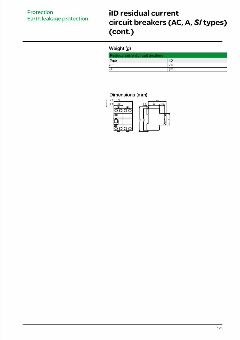
7/16/2019 Acti9 Launch Catalogue
http://slidepdf.com/reader/full/acti9-launch-catalogue 123/124123
Dimensions (mm)
D B 1 2 2 7 7 5
8596
445.5 202 P
4 P 72
36
69
45
Weight (g)
Residual current circuit breakers
Type iID
2P 210
4P 370
iID residual current
circuit breakers (AC, A, SI types)
(cont.)
Protection
Earth leakage protection
7/16/2019 Acti9 Launch Catalogue
http://slidepdf.com/reader/full/acti9-launch-catalogue 124/124
UK contact details -
0870 608 8 608Fax 0870 608 8 606
Ireland contact details -
01 601 2200Fax 01 601 2201
As the global specialist in energy management with operations in morethan 100 countries, Schneider Electric offers integrated solutions acrossmultiple market segments, including leadership positions in energyand infrastructure, industrial processes, building automation, and datacentres/networks, as well as a broad presence in residential applications.
Schneider Electric is dedicated to making individuals’ and organisations’energy safe, reliable, efficient, productive and green from Power Plant toPlugTM.
We are changing our brand names and becoming one Schneider Electric.
You’ll get the same great quality products, but rom one name you can remember andtrust. This provides you and your customers with the reassurance associated with
Schneider Electric.
Some o our market leading brands have already become Schneider Electric including
Merlin Gerin, Telemecanique, Square D, GET, Mita, Sarel, Himel, Thorsman,
Tower and TAC.
Working as one Schneider Electric makes it clearer that our ranges are highly compatible